Solution of the Kalman ἀltering problem in control and modeling of a ...
8
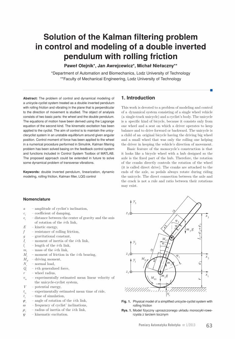
Pomiary Automatyka Robotyka nr 1/2013 63 Solution of the Kalman filtering problem in control and modeling of a double inverted pendulum with rolling friction Paweł Olejnik*, Jan Awrejcewicz*, Michał Niełaczny** *Department of Automation and Biomechanics, Lodz University of Technology **Faculty of Mechanical Engineering, Lodz University of Technology Abstract: The problem of control and dynamical modeling of a unicycle-cyclist system treated as a double inverted pendulum with rolling friction and vibrating in the plane that is perpendicular to the direction of movement is studied. The object of analysis consists of two basic parts: the wheel and the double pendulum. The equations of motion have been derived using the Lagrange equation of the second kind. The kinematic excitation has been applied to the cyclist. The aim of control is to maintain the unicy- clecyclist system in an unstable equilibrium around given angular position. Control moment of force has been applied to the wheel in a numerical procedure performed in Simulink. Kalman filtering problem has been solved basing on the feedback control system and functions included in Control System Toolbox of MATLAB. The proposed approach could be extended in future to solve some dynamical problem of transverse vibrations. Keywords: double inverted pendulum, linearization, dynamic modeling, rolling friction, Kalman filter, LQG control Nomenclature a – amplitude of cyclist’s inclination, c i – coefficient of damping, e i – distance between the center of gravity and the axis of rotation of the i-th link, E – kinetic energy, f – resistance of rolling friction, g – gravitational constant, I i – moment of inertia of the i-th link, l i – length of the i-th link, m i – mass of the i-th link, M i – moment of friction in the i-th bearing, M N – driving moment, N c – normal load, Q i – i-th generalized force, r – wheel radius, v m – experimentally estimated mean linear velocity of the unicycle-cyclist system, V – potential energy, t m – experimentally estimated mean time of ride, t 1 – time of simulation, j i – angle of rotation of the i-th link, w – frequency of cyclist’ inclinations, r i – radius of inertia of the i-th link, y – kinematic excitation. 1. Introduction This work is devoted to a problem of modeling and control of a dynamical system consisting of a single wheel vehicle (a single-track unicycle) and a cyclist’s body. The unicycle is a specific kind of bicycle, because it consists only from one wheel and a seat on which a driver operates to keep balance and to drive forward or backward. The unicycle is a child of an original bicycle having the driving big wheel and a small wheel that was only the rolling one helping the driver in keeping the vehicle’s direction of movement. Basic feature of the monocycle’s construction is that it looks like a bicycle wheel with a hub designed so the axle is the fixed part of the hub. Therefore, the rotation of the cranks directly controls the rotation of the wheel (it is called direct drive). The cranks are attached to the ends of the axle, so pedals always rotate during riding the unicycle. The direct connection between the axle and the crack is not a rule and ratio between their rotations may exist. Fig. 1. Physical model of a simplified unicycle-cyclist system with rolling friction Rys. 1. Model fizyczny uproszczonego układu monocykl-rowe- rzysta z tarciem tocznym
Transcript of Solution of the Kalman ἀltering problem in control and modeling of a ...
Pomiary Automatyka Robotyka nr 1/2013 63
Solution of the Kalman filtering problem in control and modeling of a double inverted
pendulum with rolling frictionPaweł Olejnik*, Jan Awrejcewicz*, Michał Niełaczny**
*Department of Automation and Biomechanics, Lodz University of Technology**Faculty of Mechanical Engineering, Lodz University of Technology
Abstract: The problem of control and dynamical modeling of a unicycle-cyclist system treated as a double inverted pendulum with rolling friction and vibrating in the plane that is perpendicular to the direction of movement is studied. The object of analysis consists of two basic parts: the wheel and the double pendulum. The equations of motion have been derived using the Lagrange equation of the second kind. The kinematic excitation has been applied to the cyclist. The aim of control is to maintain the unicy-clecyclist system in an unstable equilibrium around given angular position. Control moment of force has been applied to the wheel in a numerical procedure performed in Simulink. Kalman filtering problem has been solved basing on the feedback control system and functions included in Control System Toolbox of MATLAB. The proposed approach could be extended in future to solve some dynamical problem of transverse vibrations.
Keywords: double inverted pendulum, linearization, dynamic modeling, rolling friction, Kalman filter, LQG control
Nomenclature
a – amplitude of cyclist’s inclination,ci – coefficient of damping,ei – distance between the center of gravity and the axis
of rotation of the i-th link,E – kinetic energy,f – resistance of rolling friction,g – gravitational constant,Ii – moment of inertia of the i-th link,li – length of the i-th link,mi – mass of the i-th link,Mi – moment of friction in the i-th bearing,MN – driving moment,Nc – normal load,Qi – i-th generalized force,r – wheel radius,vm – experimentally estimated mean linear velocity of
the unicycle-cyclist system,V – potential energy,tm – experimentally estimated mean time of ride,t1 – time of simulation,ji – angle of rotation of the i-th link,w – frequency of cyclist’ inclinations,ri – radius of inertia of the i-th link,y – kinematic excitation.
1. Introduction
This work is devoted to a problem of modeling and control of a dynamical system consisting of a single wheel vehicle (a single-track unicycle) and a cyclist’s body. The unicycle is a specific kind of bicycle, because it consists only from one wheel and a seat on which a driver operates to keep balance and to drive forward or backward. The unicycle is a child of an original bicycle having the driving big wheel and a small wheel that was only the rolling one helping the driver in keeping the vehicle’s direction of movement.
Basic feature of the monocycle’s construction is that it looks like a bicycle wheel with a hub designed so the axle is the fixed part of the hub. Therefore, the rotation of the cranks directly controls the rotation of the wheel (it is called direct drive). The cranks are attached to the ends of the axle, so pedals always rotate during riding the unicycle. The direct connection between the axle and the crack is not a rule and ratio between their rotations may exist.
Fig. 1. Physical model of a simplified unicycle-cyclist system with rolling friction
Rys. 1. Model fizyczny uproszczonego układu monocykl-rowe-rzysta z tarciem tocznym
64
NAukA
Riding the unicycle is not easy. It is caused by single tracking of the vehicle that requires to keep balance of the system simultaneously in two planes. Moreover, to ride comfortably the distance between the saddle and the lowest pedal position has to be smaller than length of the cyclist’s leg. In a consequence, center of gravity of the cyclist’s body lies a bit upper than his normal upright position.
To keep balance in plane that is parallel to the direction of riding (forward or backward) the cyclist has to accelerate or slow the driving wheel to maintain his center of gravity perpendicularly above the axle of rotation of the wheel. To keep balance in plane that is transversal to the direction of riding the cyclist has to balance from left to right side with the use of his loins.
Construction and mechanics of a unicycle allows to consider it as an inverted double pendulum (see fig. 1). The first link is created by the cyclist’s body, and the second link by the fork frame stiffly joined with the seat post (a link between the frame and saddle). Considering, that the wheel states the third link, so a kind of triple pendulum could be even assumed.
The system visible in fig. 1 has three degrees of freedom and to control it one would involve a control moment of force applied to the driving wheel or in the joint created by the rotational connection between the second and third link.
of freedom realizations of inverted pendulum systems. Balancing of inverted pendulums of any kinds is a classic control problem of some 30 years.
A new fuzzy controller for stabilizing series-type double inverted pendulum systems is proposed in [12] based on the SIRMs (Single Input Rule Modules) dynamically connected fuzzy inference model. The proposed controller deals with six input items. Each input item is provided with a SIRM and a dynamic importance degree (DID). The SIRM and the DID are set up such that the angular control of the upper pendulum takes the highest priority order over the angular control of the lower pendulum and the position control of the cart when the relative angle of the upper pendulum is big. By using the SIRMs and the DIDs, the control priority orders are automatically adjusted according to control situations. Simulation results show that the controller stabilizes series-type double inverted pendulum systems of different parameter values in about 10 seconds for a wide range of the initial angles.
In [6] an adaptive fuzzy logic control of dynamic balance and motion is investigated for wheeled inverted pendulums with parametric and functional uncertainties. The proposed adaptive fuzzy logic control based on physical properties of wheeled inverted pendulums makes use of a fuzzy logic engine and a systematic online adaptation mechanism to approximate the unknown dynamics. Based on Lyapunov synthesis, the fuzzy control ensures that the system outputs track the given bounded reference signals to within a small neighborhood of zero, and guarantees semi-global uniform boundedness of all closed-loop signals. The effectiveness of the proposed control is verified through extensive simulations.
Contribution [9] deals with the application of energy based control methods for a model of inverted pendulum on a cart. A swing-up controller as well as a nonlinear balancing controller with the focus on the implementation on a laboratory model is presented. The well-known control concepts has been adapted such that they work on a concrete experiment with all the undesirable effects like friction and quantization.
In [7] a linear state feedback design technique for balancing an inverted pendulum is provided. The pivot of the investigated pendulum is mounted on a carriage that has limited horizontal travel. For any given (arbitrarily small) allowable travel of the carriage, a linear state feedback controller that balances the pendulum with an infinite amount of gain margin has been adopted in the sense that, if the feedback gain is perturbed by any multiplying factor greater than one, the controller balances the pendulum without requiring greater traveling distance than the maximum allowable.
A mathematical model of a planar double inverted pendulum was established in [13] by means of analytical dynamics method. Based on the linear quadratic optimal theory, a LQR self-adjusting controller was derived. Further the output of LQR controller was refined through optimize factor which was the function of the states of planar pendulum, and on account of that, control action exerted on the pendulum was improved. Simulation results together with pilot scale experiment verify the efficacy of the suggested scheme.
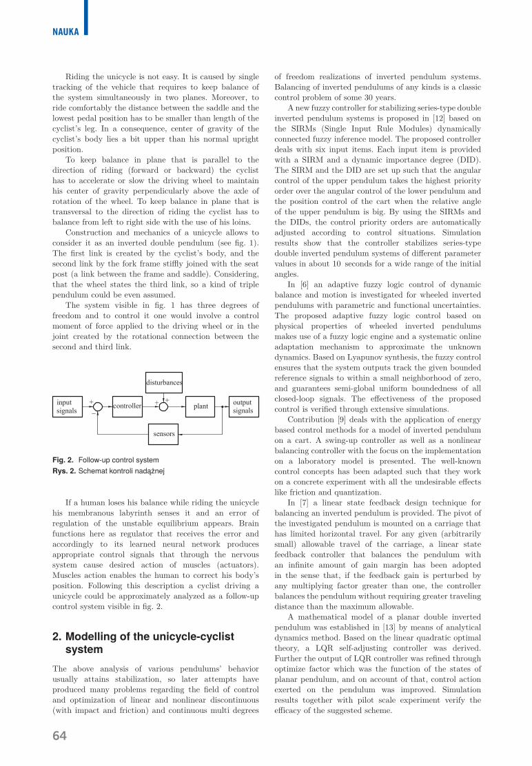
Fig. 2. Follow-up control systemRys. 2. Schemat kontroli nadążnej
If a human loses his balance while riding the unicycle his membranous labyrinth senses it and an error of regulation of the unstable equilibrium appears. Brain functions here as regulator that receives the error and accordingly to its learned neural network produces appropriate control signals that through the nervous system cause desired action of muscles (actuators). Muscles action enables the human to correct his body’s position. Following this description a cyclist driving a unicycle could be approximately analyzed as a follow-up control system visible in fig. 2.
2. Modelling of the unicycle-cyclist system
The above analysis of various pendulums’ behavior usually attains stabilization, so later attempts have produced many problems regarding the field of control and optimization of linear and nonlinear discontinuous (with impact and friction) and continuous multi degrees
Pomiary Automatyka Robotyka nr 1/2013 65
Work [10] uses the symbolic manipulation toolbox available in MATLAB to investigate pole-zero cancellation of the uncontrollable double inverted pendulum algebraically, following exploratory numerical computation. The ability of the software to factorize complicated multivariable polynomials is exploited to identify, in algebraic form, the anticipated pole-zero term cancelling throughout the transfer functions of the uncontrollable pendulum system. The investigated system has been considered with respect to the force on the trolley, for which it is a conditionally uncontrollable problem, and with respect to each of the torques on the arms, which are unconditionally uncontrollable problems.
A methodology of Lyapunov stability control is presented in [11] to achieve the upright balance of a base-excited inverted pendulum with two degrees of rotational freedom. The inclusion of the base point movement led to the dynamic system of such a pendulum which is non-autonomous and is under persistent disturbance. An idealized piecewise continuous control strategy was designed, and for the obtained controller the solution trajectories to be arbitrarily close to the upright position have been guaranteed. The continuous control law guarantees that the solution trajectories are kept in a controlled region around the upright position. The stability has been traded off with a weaker stability to prevent chattering. The robustness of the controllers with respect to certain class of uncertainties was also examined.
A passive fault tolerant control scheme has been suggested in [8]. A nominal controller is augmented with an additional block, which guarantees stability and performance after the occurrence of a fault. The method is based on parameterization, which requires the nominal controller to be implemented in observer based form. The proposed method is applied to a double inverted pendulum system, for which the H∞ controller has been designed and verified in a lab setup.
The literature overview shows that the problem is still valid, states a good field for practicing in control of multi degrees of freedom systems, as well as opens new perspectives for application of interesting structures of controllers.
One of such simple structures that are based on the standard LQG control has been studied in this work. Application of the Kalman filtering problem to solve such kinds of continuous systems is, in general, not examined in literature. An exemplary contribution [5] that uses a Kalman filter to help the estimation of a gyro angle presents some study devoted to balancing and navigation of a MIPS robot. It is a mobile inverted pendulum system whose structure is a combination of a wheeled mobile robot and an inverted pendulum system. Low cost gyro and tilt sensors are used and fused to detect balancing angle. Digital filters are selectively designed for sensors to measure an inclined angle accurately with respect to different frequencies. Performances of balancing and navigation of the MIPS are tested by experimental studies through remote control.
Let us take into analysis a simplified model of unicycle-cyclist system in fig. 1. Assuming that the most upper link is the cyclist’s body and the remaining two are
the unicycle’s links, it creates a physical model placed in Cartesian coordinates.
Physical model of the unicycle-cyclist system consists of three solid bodies of which masses are focused in points of their centers of gravity: 1) the driving wheel, 2) fork frame with the seat post, 3) cyclist’s body. Equations of motion have been derived by means of Lagrange equation of second kind [1]
, 1, 2, ..., ,n
n n n
d E E V Q n Ndt q q q
∂ ∂ ∂- + = = ∂ ∂ ∂ �
(1)
where: N is the number of generalized coordinates, qn is the n-th coordinate.
In the analysis we will assume that j1, j2, j3 are the ge-neralized coordinates, but if to regard, that a cyclist riding the unicycle can incline forward and backward with a fre-quency w in the direction of movement
( ) ( ) ( )3 2 , sint t a tϕ ϕ ψ ψ ω= - = , (2)
where: y(t) – angle of cyclist’s body around the saddle.
Having the above one rewrites eq. (1) as follows
, 1, 2.n
n n n
d E E V Q ndt ϕ ϕ ϕ
∂ ∂ ∂- + = = ∂ ∂ ∂ �
(3)
Moments of inertia Ii of i-th link with respect to axes perpendicular to centre of gravity of i-th mass are given by the formula
2, 1, , 3i i iI m iρ= = … , (4)
where corresponding radii of inertia are as follows
2 3
1 2 33 3, , .
3 3e erρ ρ ρ= = = (5)
Distances between centers of gravity and the correspon-ding axes of rotation ei are as follows
0.5 , 2, 3.i ie l i= = (6)
Kinetic energy E of the unicycle-cyclist system is a sum of kinetic energies of the linear and angular displacement of each mass
( )
32 2 2 2
1 2i
i i i ii
mE x y ρ ϕ=
= + + ∑ �� � . (7)
Gravitational forces are conservative, so potential ener-gy with respect to each mass of the system reads
1 1 2 2 3 3V m gy m gy m gy= + + . (8)
Assuming that the direct driving wheel is stiff and rolls without slips the integrable geometrical and kinematic con-straints are superposed
66
NAukA
1 1 1, .x r y rϕ= = (9)
In accordance to the above assumptions the following relations between Cartesian and generalized coordinates are found
( )( )( )( )
2 1 2 2
2 1 2 2
3 1 3 2 2 2
3 1 3 2 2 2
sin ,cos ,sin sin sin ,
cos sin cos .
x x ey y ex x e a t l
y y e a t l
ϕϕϕ ω ϕ
ϕ ω ϕ
= += +
= + - +
= + - +
(10)
For estimation of generalized forces we need to assume some non-conservative forces: normal force Nc and any re-sistances in joints. Generalized coordinates describe abso-lute angular displacements, therefore moments of forces ac-ting on appropriate links are taken as the generalized forces
1 01 21 2 12,NQ M M M Q M= - + = . (11)
Dynamics of the system will be investigated while riding with constant velocity. At this condition moments acting on the wheel with respect to z1 axis have to balance them-selves. If links 2 and 3 move forward with constant veloci-ty keeping their upright positions in directions x2 and x3, respectively, then the driving moment MN is equal to the moment of rolling resistance
1 2 3( )NM m m m fg= + + . (12)
Additionally, moment of rolling resistance is given by
01 sgn i cM f Nϕ= � , (13)
where normal force Nc reads
3 3
1 1c i i i
i iN g m m y
= =
= + ∑ ∑ �� . (14)
Moment generated by the viscous damping of frame
( )12 2 2 1 21M c Mϕ ϕ= - - = -� � . (15)
Generalized forces are finally found in the form
(16)
By substitution of eqs. (7), (8) and (15) in (1) we found in Mathematica the two ordinary differential equations of second order describing the reduced dynamical model of the unicycle-cyclist system
( )( ) ( )( )( )(( ( )( )(( ( ) ( )( )(( ( ) ( )( )
( ) ( )( )) ( )( )) )( )) ( ) )
23 3 1 2 2 3 2
22 3 3 2 2
2 1 2 2
22 1 2 2 2 2 3 2 2 2
1/6 3 sin sin sin sin 2 sin
3 2 cos sin sin cos sin sin
sin cos sin 2 cos sin 2 cos 2 sin
cos sin 2 3
l m r a t g a t l a t
l m l a t a t a t a t
t a t a t r g
m r g l m m c
ϕ ω ϕ ω ϕ ϕ ω ω
ω ϕ ω ω ϕ ω ω ω
ω ω ω ϕ ω ϕ ϕ ϕ
ϕ ϕ ϕ ϕ ϕ
- + - + + +
+ - - + +
+ + - +
+ - + + + -
� ��
�
�� ��
�� �� �( )1 0.ϕ =�
(17a)
( )( ) ( )( )(( ( )( )( ) ( )( ) ( ) ( )( )( ))
( )( ) ( ) ) ( )
( ) ( )( ) ( )( )( )
3 3 2 2 2 2 2
2 22 2
22 2 3 2 2 2 2 1 2 3 1 2 2 1
21 3 3 2
3
1/2 sin sin 2 cos cos sin
cos sin sin sin cos sin
2 sin cos 2 2
1sgn sin sin sin2
cos sin
r l m a t a t a t
a a t a t t a t
l m m m m m r c
m l a t a t
l a t
ϕ ω ϕ ϕ ω ω ϕ ω ϕ
ω ω ω ϕ ω ω ϕ
ϕ ϕ ϕ ϕ ϕ ϕ ϕ
ϕ ω ϕ ω ω
ω
- - + - +
+ - + - +
- + - + + + - - +
+ - + +
-
� � ��
� �� �� � �
�
( ) ( )( )
( ) ( )
2 22 2 2 2 2
22 2 2 2 2 2 2 2 2 1 2 3
cos 2 cos12 sin cos sin ,2 N
a t l
l l m g m m m M
ϕ ϕ ω ω ϕ ϕ
ϕ ϕ ϕ ϕ ϕ ϕ
- - - +
- - + + + + =
� �
�� � ��
(17b)
3. Numerical Solution of dynamics
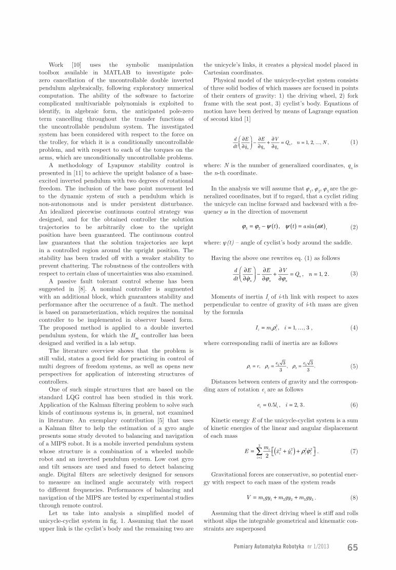
Numerical solution of the unicycle-cyclist sys-tem has been preceded by experimental estima-tion of some parameters. It was found that at a normal use of the unicycle that rides on a concre-te road the mean linear velocity of driving vm » 3 m/s,and the corresponding mean angular velocity of the wheel dj1/dt » 10 rad/s. Other parameters of an exemplary uni-cycle read: m1 = 5 kg, m2 = 30 kg, r = 0.3 m, l2 = 1 m, l3 = 0.8 m, e2 = 0.5 m, e3 = 0.4 m, c2 = 0.01 Nm/s, a = 0.25 m, w = 4.7 rad/s, f = 0.02 m, t1 = 10 s.
Fig. 3. A stroboscopic view on motion of the unicycle-cyclist system
Rys. 3. Stroboskopowy widok ruchu układu monocykl-rowerzysta
Pomiary Automatyka Robotyka nr 1/2013 67
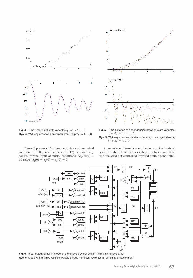
Fig. 5. Time histories of dependencies between state variables xi and yi for i = 1, ..., 3
Rys. 5. Wykresy czasowe zależności między zmiennymi stanu xi i yi przy i = 1, ..., 3
Fig. 4. Time histories of state variables φi for i = 1, ..., 3Rys. 4. Wykresy czasowe zmiennych stanu φi przy i = 1, ..., 3
fi1’fi1
fi2’fi2
fi2"
fi1"
1fi2
wt
Out1
w*t
sinwt
sinfi2
sinasinwt_fi2
sinasinwt
sgnpfi1
Out1
mian
coswt_2
coswt
cosfi2
cosasinwt_fi2
cosasinwt
Out1
a*sin(wt−fi2)
Out1
a*sin(wt)
cos
sin
cos
sin
cos
sin
cos
sin
P2
P1
O22
O11
N12
M22
M21
M12
M11
s
1
s
1
s
1
s
1
pfi1
fi2
mian
c2
coswt
fi2
pfi1
1MN
Figure 3 presents 15 subsequent views of numerical solution of differential equations (17) without any control torque input at initial conditions: dj1/dt(0) = 10 rad/s, j1(0) = j2(0) = j3(0) = 0.
Comparison of results could be done on the basis of state variables' time histories shown in figs. 5 and 6 of the analyzed not controlled inverted double pendulum.
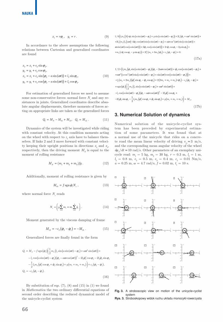
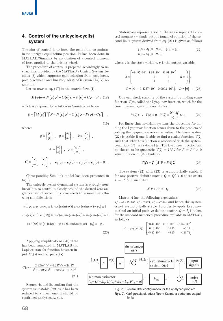
Fig. 6. Input-output Simulink model of the unicycle-cyclist system (‘simulink_unicycle.mdl’) Rys. 6. Model w Simulinku wejście-wyjście układu monocykl-rowerzysta (‘simulink_unicycle.mdl’)
68
NAukA
4. Control of the unicycle-cyclist system
The aim of control is to force the pendulum to mainta-in its upright equilibrium position. It has been done in MATLAB/Simulink by application of a control moment of force applied to the driving wheel.
The procedure of control is prepared accordingly to in-structions provided by the MATLAB’s Control System To-olbox [3] which supports: gain selection from root locus, pole placement and linear-quadratic-Gaussian (LQG) re-gulation.
Let us rewrite eq. (17) in the matrix form [1]:
( ) ( ) ( ) ( )2M N O P C Fϕ ϕ ϕ ϕ ϕ ϕ ϕ ϕ+ + + + =�� � � � , (18)
which is prepared for solution in Simulink as below
( ) ( ) ( ) ( )1 2M F N O P Cϕ ϕ ϕ ϕ ϕ ϕ ϕ ϕ-
= - - - - �� � � � ,
(19)where:
1
2
ϕϕ
ϕ
=
, 1
2
ϕϕ
ϕ
=
��
� , 1
2
ϕϕ
ϕ
=
����
�� ,
21222
ϕϕ
ϕ =
��
�,
0NM
F =
,
2 2
2 2
c cC
c c-
= - , 1 1 2 2(0) (0) (0) (0) 0ϕ ϕ ϕ ϕ= = = =� � .
Corresponding Simulink model has been presented in fig. 6.
The unicycle-cyclist dynamical system is strongly non-linear but to control it closely around the desired zero an-gle position of second link, one needs to assume the follo-wing simplifications
.
(20)
Applying simplifications (20) there has been computed in MATLAB the Laplace transfer function between in-put MN(s) and output j2(s)
( )10 2 4
3 6 2 5 62,328 4,237 28,37
1,495 1,626 9,181e s e sG s
s e s e s e
- - +=
+ - -
(21)
Figures 4a and 5a confirm that the system is unstable, but as it has been reduced to a linear one, it should be confirmed analytically, too.
State-space representation of the single input (the con-trol moment) – single output (angle of rotation of the se-cond link) system derived from eq. (21) is given as follows
0 0( ) ( ) ( ), ( ) ,
( ) ( ) ( ),
t A t Bu t t
t C t Du t
ζ ζ ζ ζ
υ ζ
= + =
= +
� (22)
where z is the state variable, u is the output variable,
5 5 514.95 10 1.63 10 91.81 10 11 0 0 , 0 ,
1 0 0A B
- ⋅ ⋅ ⋅ = =
[ ]5 50 0.4237 10 0.0003 10 . , 0C D = - ⋅ ⋅ = . (23)
One can check stability of the system by finding some function V(x), called the Lyapunov function, which for the time invariant system takes the form
( ) 0, (0) 0, ( ) 0.V dV V V
dtζζ ζ
ζ∂
> = = ≤∂
� (24)
For linear time invariant systems the procedure for fin-ding the Lyapunov function comes down to the problem of solving the Lyapunov algebraic equation. The linear system (22) is stable if one is able to find a scalar function V(z) such that when this function is associated with the system, conditions (24) are satisfied [2]. The Lyapunov function can be chosen to be quadratic V(z) = zTP z for P = P T > 0which in view of (22) leads to
( )( ) .T TV A P PAζ ζ ζ= +� (25)
The system (22) with (23) is asymptotically stable if for any positive definite matrix Q = QT > 0 there exists P = PT > 0 such that
.TA P PA Q+ = - (26)
Matrix A has the following eigenvalues:and hence this system
is not asymptotically stable. In order to apply Lyapunov method an initial positive definite matrix Q = I3 is taken for the standard numerical procedure available in MATLAB as follows
( )
8 4 8
4
8
33.44 10 0.16 10 5.45 10, 0.16 10 24.33 3.15 .
5.45 10 3.15 149.74
TP lyap A Q
- - -
-
-
⋅ ⋅ - ⋅ = = ⋅ - - ⋅ - -
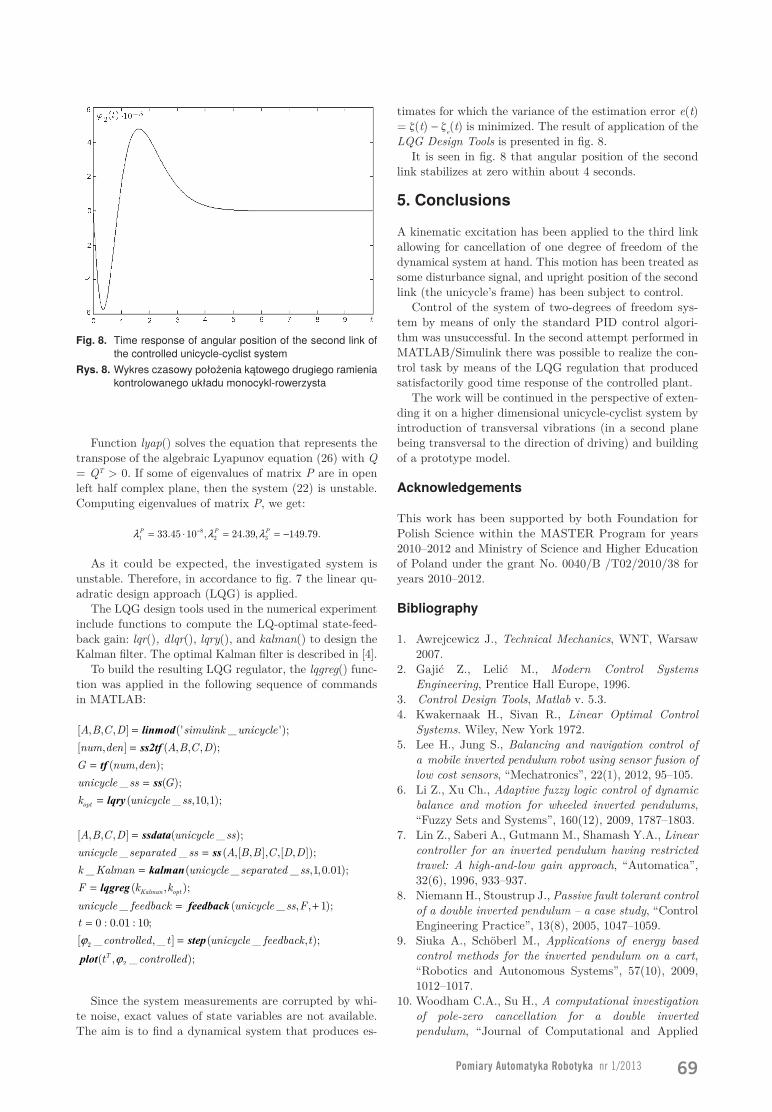
Fig. 7. System filter configuration for the analyzed problemRys. 7. Konfiguracja układu z filtrem Kalmana badanego zagad-
nienia
Pomiary Automatyka Robotyka nr 1/2013 69
Function lyap() solves the equation that represents the transpose of the algebraic Lyapunov equation (26) with Q = QT > 0. If some of eigenvalues of matrix P are in open left half complex plane, then the system (22) is unstable. Computing eigenvalues of matrix P, we get:
8
1 2 333.45 10 , 24.39, 149.79.P P Pλ λ λ-= ⋅ = = -
As it could be expected, the investigated system is unstable. Therefore, in accordance to fig. 7 the linear qu-adratic design approach (LQG) is applied.
The LQG design tools used in the numerical experiment include functions to compute the LQ-optimal state-feed-back gain: lqr(), dlqr(), lqry(), and kalman() to design the Kalman filter. The optimal Kalman filter is described in [4].
To build the resulting LQG regulator, the lqgreg() func-tion was applied in the following sequence of commands in MATLAB:
[ , , , ] (' _ ');[ , ] ( , , , );
( , );_ ( );( _ ,10,1);opt
A B C D simulink unicyclenum den A B C DG num denunicycle ss Gk unicycle ss
==
==
=
linmod
ss2tf
tf
ss
lqry
[ , , , ] ( _ );_ _ ( ,[ , ], ,[ , ]);
_ ( _ _ ,1,0.01);( , );
_ ( _ , , 1);0 : 0.01 : 10;
[
Kalman opt
A B C D unicycle ssunicycle separated ss A B B C D Dk Kalman unicycle separated ssF k kunicycle feedback unicycle ss Ftϕ
==
==
= +=
ssdata
ss
kalman
lqgreg
feedback
2
2
_ ,_ ] ( _ , );( , _ );T
controlled t unicycle feedback tt controlledϕ
= step
plot
Since the system measurements are corrupted by whi-te noise, exact values of state variables are not available. The aim is to find a dynamical system that produces es-
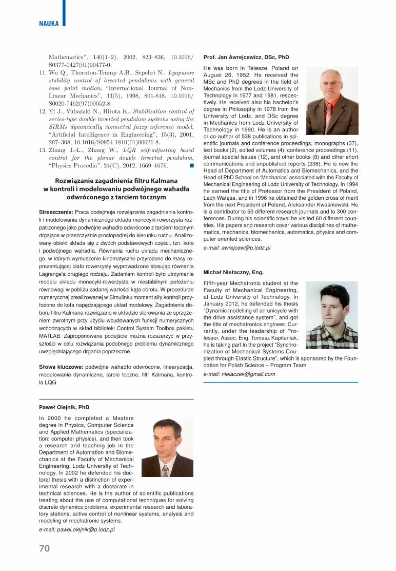
timates for which the variance of the estimation error e(t) = z(t) - ze(t) is minimized. The result of application of the LQG Design Tools is presented in fig. 8.
It is seen in fig. 8 that angular position of the second link stabilizes at zero within about 4 seconds.
5. Conclusions
A kinematic excitation has been applied to the third link allowing for cancellation of one degree of freedom of the dynamical system at hand. This motion has been treated as some disturbance signal, and upright position of the second link (the unicycle’s frame) has been subject to control.
Control of the system of two-degrees of freedom sys-tem by means of only the standard PID control algori-thm was unsuccessful. In the second attempt performed in MATLAB/Simulink there was possible to realize the con-trol task by means of the LQG regulation that produced satisfactorily good time response of the controlled plant.
The work will be continued in the perspective of exten-ding it on a higher dimensional unicycle-cyclist system by introduction of transversal vibrations (in a second plane being transversal to the direction of driving) and building of a prototype model.
Acknowledgements
This work has been supported by both Foundation for Polish Science within the MASTER Program for years 2010–2012 and Ministry of Science and Higher Education of Poland under the grant No. 0040/B /T02/2010/38 for years 2010–2012.
Bibliography
1. Awrejcewicz J., Technical Mechanics, WNT, Warsaw 2007.
2. Gajić Z., Lelić M., Modern Control Systems Engineering, Prentice Hall Europe, 1996.
3. Control Design Tools, Matlab v. 5.3.4. Kwakernaak H., Sivan R., Linear Optimal Control
Systems. Wiley, New York 1972.5. Lee H., Jung S., Balancing and navigation control of
a mobile inverted pendulum robot using sensor fusion of low cost sensors, “Mechatronics”, 22(1), 2012, 95–105.
6. Li Z., Xu Ch., Adaptive fuzzy logic control of dynamic balance and motion for wheeled inverted pendulums, “Fuzzy Sets and Systems”, 160(12), 2009, 1787–1803.
7. Lin Z., Saberi A., Gutmann M., Shamash Y.A., Linear controller for an inverted pendulum having restricted travel: A high-and-low gain approach, “Automatica”, 32(6), 1996, 933–937.
8. Niemann H., Stoustrup J., Passive fault tolerant control of a double inverted pendulum – a case study, “Control Engineering Practice”, 13(8), 2005, 1047–1059.
9. Siuka A., Schöberl M., Applications of energy based control methods for the inverted pendulum on a cart, “Robotics and Autonomous Systems”, 57(10), 2009, 1012–1017.
10. Woodham C.A., Su H., A computational investigation of pole-zero cancellation for a double inverted pendulum, “Journal of Computational and Applied
Fig. 8. Time response of angular position of the second link of the controlled unicycle-cyclist system
Rys. 8. Wykres czasowy położenia kątowego drugiego ramienia kontrolowanego układu monocykl-rowerzysta
70
NAukA
Mathematics”, 140(1–2), 2002, 823–836, 10.1016/S0377-0427(01)00477-0.
11. Wu Q., Thornton-Trump A.B., Sepehri N., Lyapunov stability control of inverted pendulums with general base point motion, “International Journal of Non-Linear Mechanics”, 33(5), 1998, 801-818, 10.1016/S0020-7462(97)00052-8.
12. Yi J., Yubazaki N., Hirota K., Stabilization control of series-type double inverted pendulum systems using the SIRMs dynamically connected fuzzy inference model, “Artificial Intelligence in Engineering”, 15(3), 2001, 297–308, 10.1016/S0954-1810(01)00021-8.
13. Zhang J.-L., Zhang W., LQR self-adjusting based control for the planar double inverted pendulum, “Physics Procedia”, 24(C), 2012, 1669–1676.
Rozwiązanie zagadnienia filtru Kalmana w kontroli i modelowaniu podwójnego wahadła
odwróconego z tarciem tocznym
Streszczenie: Praca podejmuje rozwiązanie zagadnienia kontro-li i modelowania dynamicznego układu monocykl-rowerzysta roz-patrzonego jako podwójne wahadło odwrócone z tarciem tocznym drgające w płaszczyźnie prostopadłej do kierunku ruchu. Analizo-wany obiekt składa się z dwóch podstawowych części, tzn. koła i podwójnego wahadła. Równania ruchu układu mechaniczne-go, w którym wymuszenie kinematyczne przyłożono do masy re-prezentującej ciało rowerzysty wyprowadzono stosując równania Lagrange’a drugiego rodzaju. Zadaniem kontroli było utrzymanie modelu układu monocykl-rowerzysta w niestabilnym położeniu równowagi w pobliżu zadanej wartości kąta obrotu. W procedurze numerycznej zrealizowanej w Simulinku moment siły kontroli przy-łożono do koła napędzającego układ modelowy. Zagadnienie do-boru filtru Kalmana rozwiązano w układzie sterowania ze sprzęże-niem zwrotnym przy użyciu wbudowanych funkcji numerycznych wchodzących w skład biblioteki Control System Toolbox pakietu MATLAB. Zaproponowane podejście można rozszerzyć w przy-szłości w celu rozwiązania podobnego problemu dynamicznego uwzględniającego drgania poprzeczne.
Słowa kluczowe: podwójne wahadło odwrócone, linearyzacja, modelowanie dynamiczne, tarcie toczne, filtr Kalmana, kontro-la LQG
Prof. Jan Awrejcewicz, DSc, PhD
He was born in Telesze, Poland on August 26, 1952. He received the MSc and PhD degrees in the field of Mechanics from the Lodz University of Technology in 1977 and 1981, respec-tively. He received also his bachelor’s degree in Philosophy in 1978 from the University of Lodz, and DSc degree in Mechanics from Lodz University of Technology in 1990. He is an author or co-author of 538 publications in sci-entific journals and conference proceedings, monographs (37), text books (2), edited volumes (4), conference proceedings (11), journal special issues (12), and other books (8) and other short communications and unpublished reports (238). He is now the Head of Department of Automatics and Biomechanics, and the Head of PhD School on ‘Mechanics’ associated with the Faculty of Mechanical Engineering of Lodz University of Technology. In 1994 he earned the title of Professor from the President of Poland, Lech Wałęsa, and in 1996 he obtained the golden cross of merit from the next President of Poland, Aleksander Kwaśniewski. He is a contributor to 50 different research journals and to 300 con-ferences. During his scientific travel he visited 60 different coun-tries. His papers and research cover various disciplines of mathe-matics, mechanics, biomechanics, automatics, physics and com-puter oriented sciences.e-mail: [email protected]
Michał Niełaczny, Eng.
Fifth-year Mechatronic student at the Faculty of Mechanical Engineering, at Lodz University of Technology. In January 2012, he defended his thesis “Dynamic modelling of an unicycle with the drive assistance system”, and got the title of mechatronics engineer. Cur-rently, under the leadership of Pro-fessor. Assoc. Eng. Tomasz Kapitaniak, he is taking part in the project “Synchro-nization of Mechanical Systems Cou-pled through Elastic Structure”, which is sponsored by the Foun-dation for Polish Science – Program Team. e-mail: [email protected]
Paweł Olejnik, PhD
In 2000 he completed a Masters degree in Physics, Computer Science and Applied Mathematics (specializa-tion: computer physics), and then took a research and teaching job in the Department of Automation and Biome-chanics at the Faculty of Mechanical Engineering, Lodz University of Tech-nology. In 2002 he defended his doc-toral thesis with a distinction of exper-imental research with a doctorate in technical sciences. He is the author of scientific publications treating about the use of computational techniques for solving discrete dynamics problems, experimental research and labora-tory stations, active control of nonlinear systems, analysis and modeling of mechatronic systems.e-mail: [email protected]