SLR2000: Progress and Future Applications
15
SLR2000: Progress and Future Applications John J. Degnan Code 920.3, NASA Goddard Space Flight Center 13th International Workshop on Laser Ranging Washington, DC October 7-11, 2002
Transcript of SLR2000: Progress and Future Applications
SLR2000: Progress and FutureApplications
John J. Degnan
Code 920.3, NASA Goddard Space Flight Center
13th International Workshop on Laser Ranging
Washington, DC
October 7-11, 2002
SLR2000 Technical Goals• Unmanned, eyesafe operation
• 24 hour laser tracking to satellites up to 22,000 Km slantrange (GPS, GLONASS, ETALON)
• One cm (1σ RMS) single shot ranging or better
• 1 mm precision normal points to LAGEOS
• Mean Time Between Failures: >4 months
• Automated two-way communications with centralprocessor via Internet
• Free of optical, electrical, and chemical hazards
• Reduce system replication cost to ~$1M per system
• Reduce network operations costs through standardizationand COTS technology utilization.
SLR2000 Unique Features
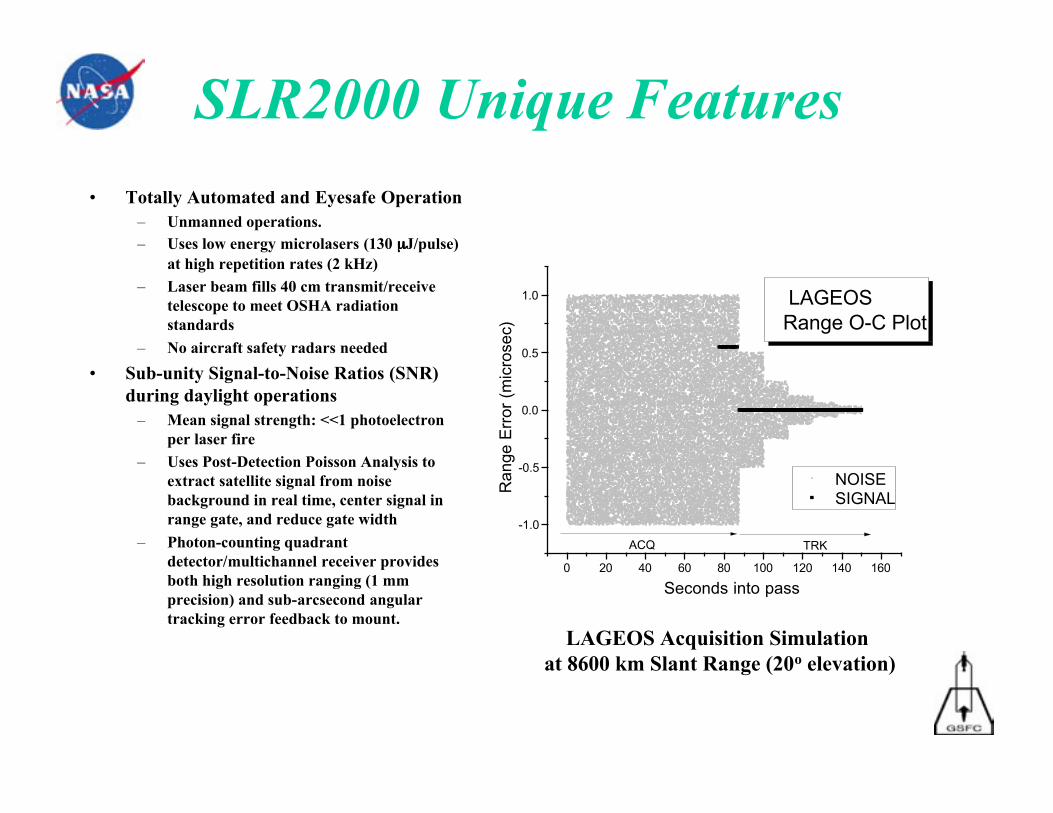
• Totally Automated and Eyesafe Operation– Unmanned operations.– Uses low energy microlasers (130 µµµµJ/pulse)
at high repetition rates (2 kHz)– Laser beam fills 40 cm transmit/receive
telescope to meet OSHA radiationstandards
– No aircraft safety radars needed
• Sub-unity Signal-to-Noise Ratios (SNR)during daylight operations
– Mean signal strength: <<1 photoelectronper laser fire
– Uses Post-Detection Poisson Analysis toextract satellite signal from noisebackground in real time, center signal inrange gate, and reduce gate width
– Photon-counting quadrantdetector/multichannel receiver providesboth high resolution ranging (1 mmprecision) and sub-arcsecond angulartracking error feedback to mount.
LAGEOS Acquisition Simulation at 8600 km Slant Range (20o elevation)
0 20 40 60 80 100 120 140 160
-1.0
-0.5
0.0
0.5
1.0
TRKACQ
LAGEOSRange O-C Plot
NOISE SIGNAL
Ran
ge E
rror
(m
icro
sec)
Seconds into pass
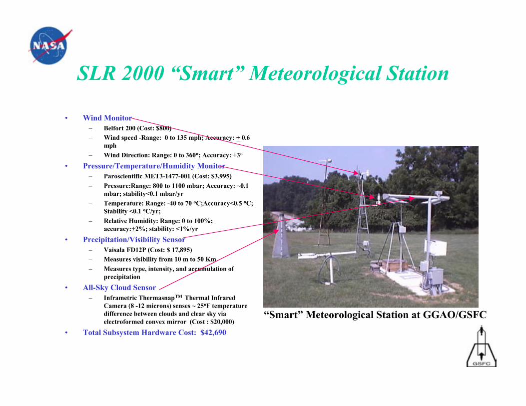
SLR 2000 “Smart” Meteorological Station
• Wind Monitor– Belfort 200 (Cost: $800)– Wind speed -Range: 0 to 135 mph; Accuracy: + 0.6
mph
– Wind Direction: Range: 0 to 360o; Accuracy: +3o
• Pressure/Temperature/Humidity Monitor– Paroscientific MET3-1477-001 (Cost: $3,995)
– Pressure:Range: 800 to 1100 mbar; Accuracy: ~0.1mbar; stability<0.1 mbar/yr
– Temperature: Range: -40 to 70 oC;Accuracy<0.5 oC;Stability <0.1 oC/yr;
– Relative Humidity: Range: 0 to 100%;accuracy:+2%; stability: <1%/yr
• Precipitation/Visibility Sensor– Vaisala FD12P (Cost: $ 17,895)– Measures visibility from 10 m to 50 Km
– Measures type, intensity, and accumulation ofprecipitation
• All-Sky Cloud Sensor– Inframetric ThermasnapTM Thermal Infrared
Camera (8 -12 microns) senses ~ 25oF temperaturedifference between clouds and clear sky viaelectroformed convex mirror (Cost : $20,000)
• Total Subsystem Hardware Cost: $42,690
“Smart” Meteorological Station at GGAO/GSFC
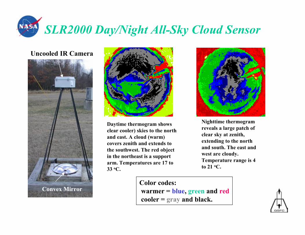
SLR2000 Day/Night All-Sky Cloud Sensor
Color codes: warmer = blue, green and red cooler = gray and black.
Daytime thermogram showsclear cooler) skies to the northand east. A cloud (warm)covers zenith and extends tothe southwest. The red objectin the northeast is a supportarm. Temperatures are 17 to33 oC.
Nighttime thermogramreveals a large patch ofclear sky at zenith,extending to the northand south. The east andwest are cloudy.Temperature range is 4to 21 oC.
Convex Mirror
Uncooled IR Camera
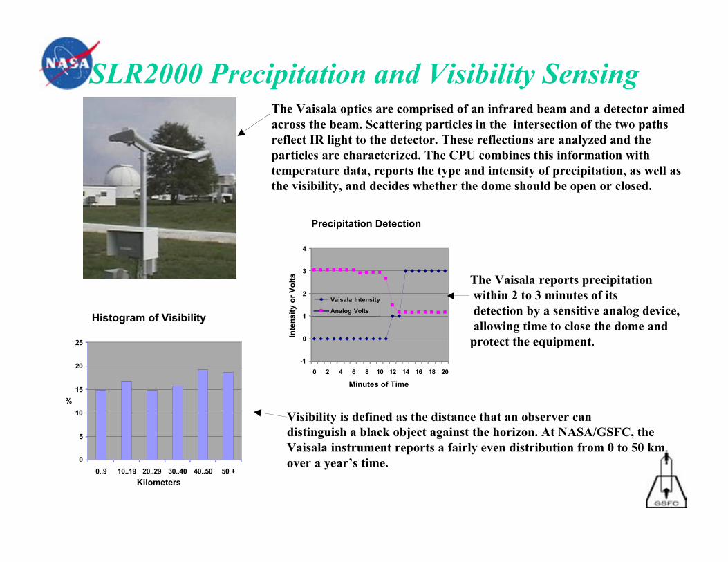
SLR2000 Precipitation and Visibility Sensing
Precipitation Detection
-1
0
1
2
3
4
0 2 4 6 8 10 12 14 16 18 20
Minutes of Time
Inte
nsi
ty o
r V
olt
sVaisala Intensity
Analog VoltsHistogram of Visibility
0
5
10
15
20
25
0..9 10..19 20..29 30..40 40..50 50 +
Kilometers
%
The Vaisala optics are comprised of an infrared beam and a detector aimedacross the beam. Scattering particles in the intersection of the two pathsreflect IR light to the detector. These reflections are analyzed and theparticles are characterized. The CPU combines this information withtemperature data, reports the type and intensity of precipitation, as well asthe visibility, and decides whether the dome should be open or closed.
The Vaisala reports precipitation within 2 to 3 minutes of its detection by a sensitive analog device, allowing time to close the dome andprotect the equipment.
Visibility is defined as the distance that an observer candistinguish a black object against the horizon. At NASA/GSFC, theVaisala instrument reports a fairly even distribution from 0 to 50 kmover a year’s time.
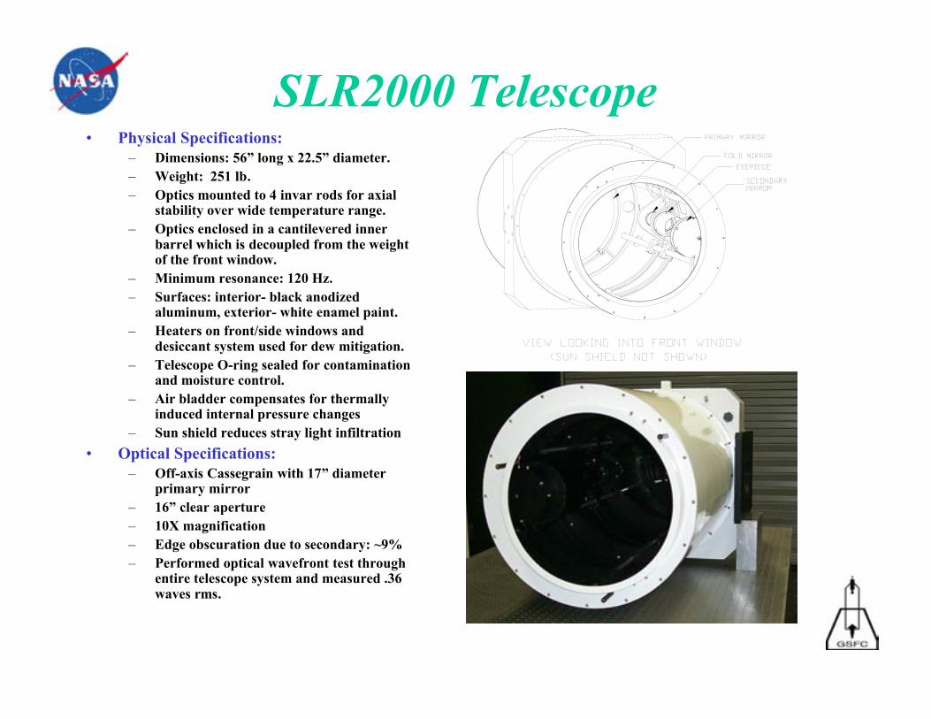
SLR2000 Telescope• Physical Specifications:
– Dimensions: 56” long x 22.5” diameter.– Weight: 251 lb.– Optics mounted to 4 invar rods for axial
stability over wide temperature range.– Optics enclosed in a cantilevered inner
barrel which is decoupled from the weightof the front window.
– Minimum resonance: 120 Hz.– Surfaces: interior- black anodized
aluminum, exterior- white enamel paint.– Heaters on front/side windows and
desiccant system used for dew mitigation.– Telescope O-ring sealed for contamination
and moisture control.– Air bladder compensates for thermally
induced internal pressure changes– Sun shield reduces stray light infiltration
• Optical Specifications:– Off-axis Cassegrain with 17” diameter
primary mirror– 16” clear aperture– 10X magnification– Edge obscuration due to secondary: ~9%– Performed optical wavefront test through
entire telescope system and measured .36waves rms.
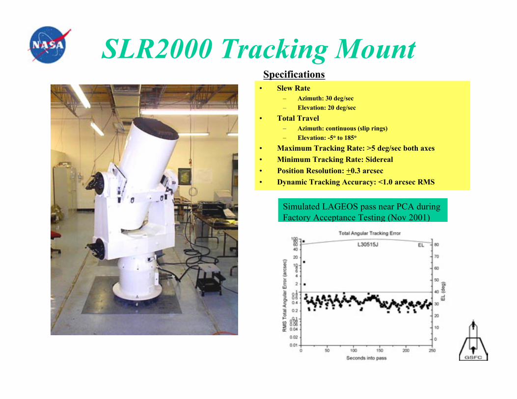
SLR2000 Tracking Mount• Slew Rate
– Azimuth: 30 deg/sec
– Elevation: 20 deg/sec
• Total Travel– Azimuth: continuous (slip rings)
– Elevation: -5o to 185o
• Maximum Tracking Rate: >5 deg/sec both axes
• Minimum Tracking Rate: Sidereal
• Position Resolution: +0.3 arcsec
• Dynamic Tracking Accuracy: <1.0 arcsec RMS
Specifications
Simulated LAGEOS pass near PCA during Factory Acceptance Testing (Nov 2001)
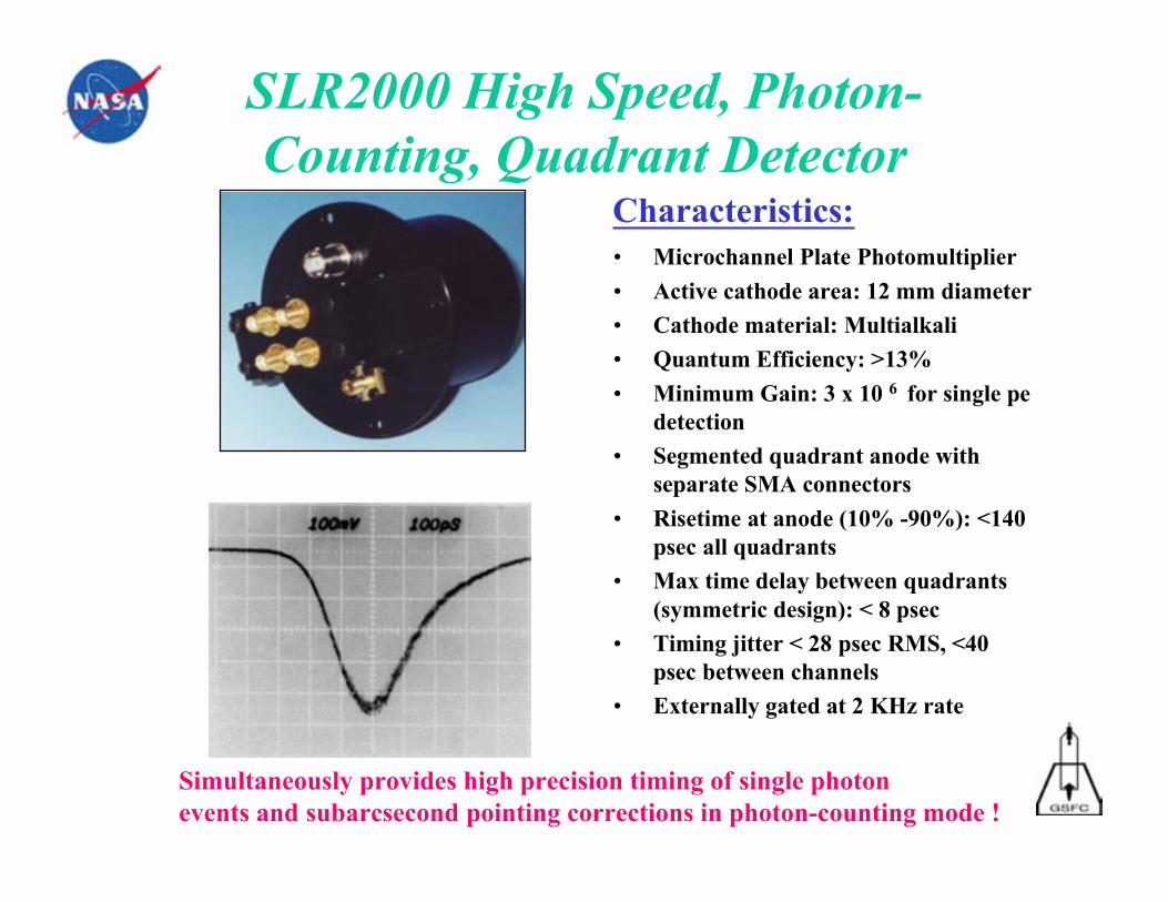
SLR2000 High Speed, Photon-Counting, Quadrant Detector
• Microchannel Plate Photomultiplier
• Active cathode area: 12 mm diameter
• Cathode material: Multialkali
• Quantum Efficiency: >13%
• Minimum Gain: 3 x 10 6 for single pedetection
• Segmented quadrant anode withseparate SMA connectors
• Risetime at anode (10% -90%): <140psec all quadrants
• Max time delay between quadrants(symmetric design): < 8 psec
• Timing jitter < 28 psec RMS, <40psec between channels
• Externally gated at 2 KHz rate
Characteristics:
Simultaneously provides high precision timing of single photonevents and subarcsecond pointing corrections in photon-counting mode !
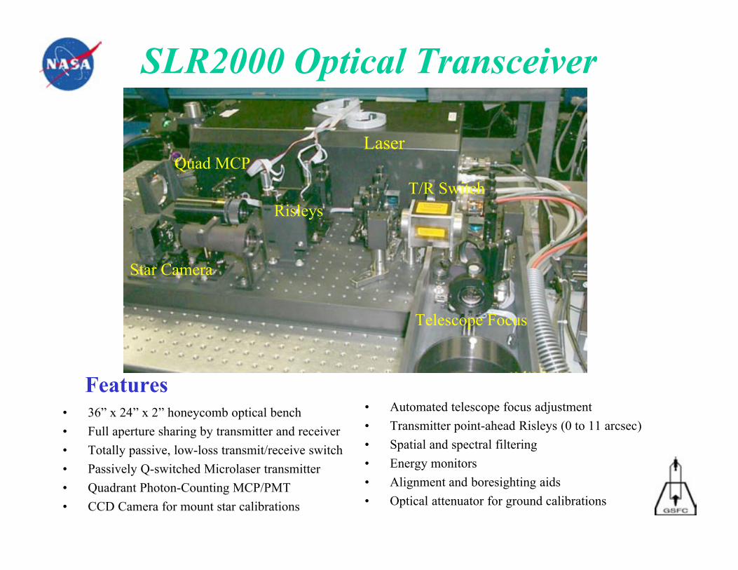
SLR2000 Optical Transceiver
• 36” x 24” x 2” honeycomb optical bench
• Full aperture sharing by transmitter and receiver
• Totally passive, low-loss transmit/receive switch
• Passively Q-switched Microlaser transmitter
• Quadrant Photon-Counting MCP/PMT
• CCD Camera for mount star calibrations
• Automated telescope focus adjustment
• Transmitter point-ahead Risleys (0 to 11 arcsec)
• Spatial and spectral filtering
• Energy monitors
• Alignment and boresighting aids
• Optical attenuator for ground calibrations
Features
Laser
Star Camera
Risleys
Telescope Focus
T/R Switch
Quad MCP
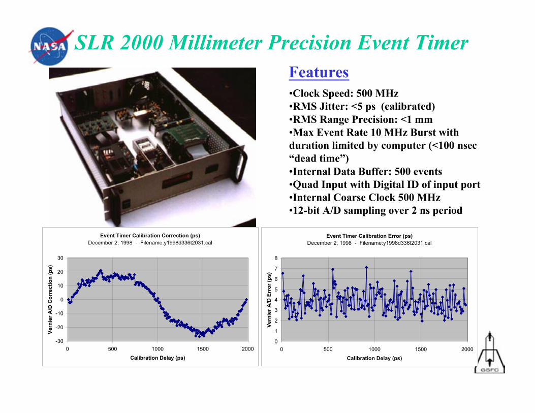
SLR 2000 Millimeter Precision Event Timer
•Clock Speed: 500 MHz•RMS Jitter: <5 ps (calibrated)•RMS Range Precision: <1 mm•Max Event Rate 10 MHz Burst withduration limited by computer (<100 nsec“dead time”)•Internal Data Buffer: 500 events•Quad Input with Digital ID of input port•Internal Coarse Clock 500 MHz•12-bit A/D sampling over 2 ns period
Features
Event Timer Calibration Correction (ps)December 2, 1998 - Filename:y1998d336t2031.cal
-30
-20
-10
0
10
20
30
0 500 1000 1500 2000
Calibration Delay (ps)
Ver
nie
r A
/D C
orr
ecti
on
(p
s)
Event Timer Calibration Error (ps)December 2, 1998 - Filename:y1998d336t2031.cal
0
1
2
3
4
5
6
7
8
0 500 1000 1500 2000
Calibration Delay (ps)
Ver
nie
r A
/D E
rro
r (p
s)
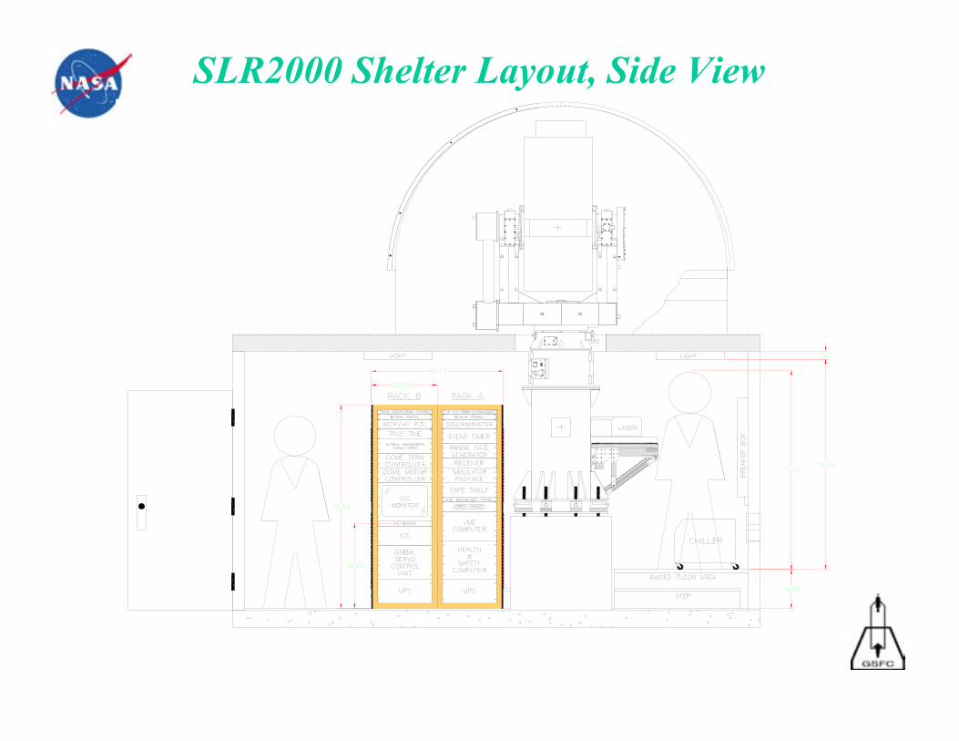
SLR2000 Shelter Layout, Side View
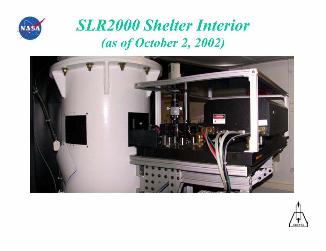
SLR2000 Shelter Interior(as of October 2, 2002)
SLR2000 Status
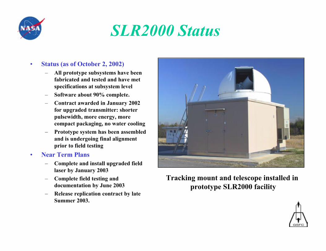
• Status (as of October 2, 2002)– All prototype subsystems have been
fabricated and tested and have metspecifications at subsystem level
– Software about 90% complete.
– Contract awarded in January 2002for upgraded transmitter: shorterpulsewidth, more energy, morecompact packaging, no water cooling
– Prototype system has been assembledand is undergoing final alignmentprior to field testing
• Near Term Plans– Complete and install upgraded field
laser by January 2003
– Complete field testing anddocumentation by June 2003
– Release replication contract by lateSummer 2003.
Tracking mount and telescope installed in prototype SLR2000 facility
Future Upgrades and Applications• Two Color Upgrade
– Technical approach described in 2000 Matera Workshop Proceedings
– Add third harmonic crystal and receiver channel for second color
– Compute range difference between different color normal points
• Interplanetary Transponder for Inner Solar System– Technical approach described in previous workshop proceedings (1996, 1998,
2000) and J. Geodynamics, November, 2002.
– Need to extend maximum transmitter point-ahead capability from current 11to 45 arcseconds
• Terminal for Automated Space-to-Ground Laser Communications– Currently working with JPL to design a modified SLR2000 system that
simultaneously ranges to, and communicates optically with, a spacecraft
– SLR2000 performs all of the field operations required to support anautomated lasercom station
• Assesses weather and cloud cover and provides necessary safety and health functions
• SLR tracking defines orbit for initial spacecraft acquisition and confirmation
• Ranging beam provides Earth beacon for space-based lasercom system to lock onto
– Simple wavelength splitter in SLR2000 diverts lasercom beam tocommunications receiver