SIGGRAPH 2006 Course Computational Ill i tiIllumination ... · Effect of Varying αin Spectral Term...
31
4/23/2009 1 Computational Ill i ti Illumination Ramesh Raskar, Computational Illumination Computational Illumination Computational Illumination SIGGRAPH 2006 Course Course WebPage: Ramesh Raskar Mitsubishi Electric Research Labs http://www.merl.com/people/raskar/photo/ Ramesh Raskar, Computational Illumination Computational Illumination Edgerton 1930’s Edgerton 1930’s Not Special Cameras but Special Lighting Edgerton 1930’s Edgerton 1930’s Multi‐flash Sequential Photography Stroboscope (Electronic Flash) Shutter Open Flash Time Ramesh Raskar, Computational Illumination Computational Illumination: Computational Illumination: • Presence or Absence, Duration, Brightness Presence or Absence, Duration, Brightness – Flash/No Flash/No-flash flash • Light color/wavelength Light color/wavelength • Light Light position position – Multi Multi-flash for depth edges flash for depth edges – Programmable dome (image re Programmable dome (image re-lighting and matting) lighting and matting) • Spatial Spatial Modulation Modulation – Dual Photography Dual Photography
Transcript of SIGGRAPH 2006 Course Computational Ill i tiIllumination ... · Effect of Varying αin Spectral Term...
4/23/2009
1
Computational Ill i tiIllumination
Ramesh Raskar, Computational Illumination
Computational IlluminationComputational Illumination
SIGGRAPH 2006 Course
Course WebPage :
Ramesh RaskarMitsubishi Electric Research Labs
ghttp://www.merl.com/people/raskar/photo/
Ramesh Raskar, Computational Illumination
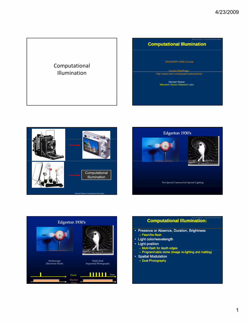
Computational Illumination
Edgerton 1930’sEdgerton 1930’s
Not Special Cameras but Special Lighting
Edgerton 1930’sEdgerton 1930’s
Multi‐flash Sequential Photography
Stroboscope(Electronic Flash)
Shutter Open
Flash Time
Ramesh Raskar, Computational Illumination
Computational Illumination:Computational Illumination:
•• Presence or Absence, Duration, BrightnessPresence or Absence, Duration, Brightness–– Flash/NoFlash/No--flashflash
•• Light color/wavelengthLight color/wavelength•• Light Light positionposition
–– MultiMulti--flash for depth edgesflash for depth edges–– Programmable dome (image reProgrammable dome (image re--lighting and matting)lighting and matting)
•• Spatial Spatial ModulationModulation–– Dual PhotographyDual Photography
4/23/2009
2
Ramesh Raskar, Computational Illumination
Computational Illumination:Computational Illumination:
•• Presence or Absence, Duration, BrightnessPresence or Absence, Duration, Brightness–– Flash/NoFlash/No--flashflash
•• Light color/wavelengthLight color/wavelength•• Light Light positionposition
–– MultiMulti--flash for depth edgesflash for depth edges–– Programmable dome (image reProgrammable dome (image re--lighting and matting)lighting and matting)
•• Spatial Spatial ModulationModulation–– Dual PhotographyDual Photography
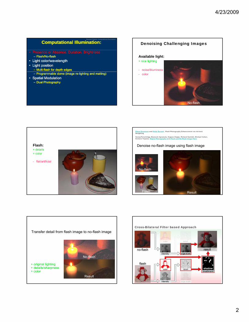
Denoising Challenging Images
Available light:+ nice lighting
- noise/blurriness- color
No-flash
Flash:+ details+ color
flat/artificial- flat/artificial
Flash
Denoise no-flash image using flash image
Elmar Eisemann and Frédo Durand , Flash Photography Enhancement via Intrinsic Relighting
Georg Petschnigg, Maneesh Agrawala, Hugues Hoppe, Richard Szeliski, Michael Cohen, Kentaro Toyama. Digital Photography with Flash and No-Flash Image Pairs
Flash
No-flash
Result
Transfer detail from flash image to no-flash image
+ original lighting+ details/sharpness+ color
Result
No-flash
Cross-Bilateral Filter based Approach
4/23/2009
3
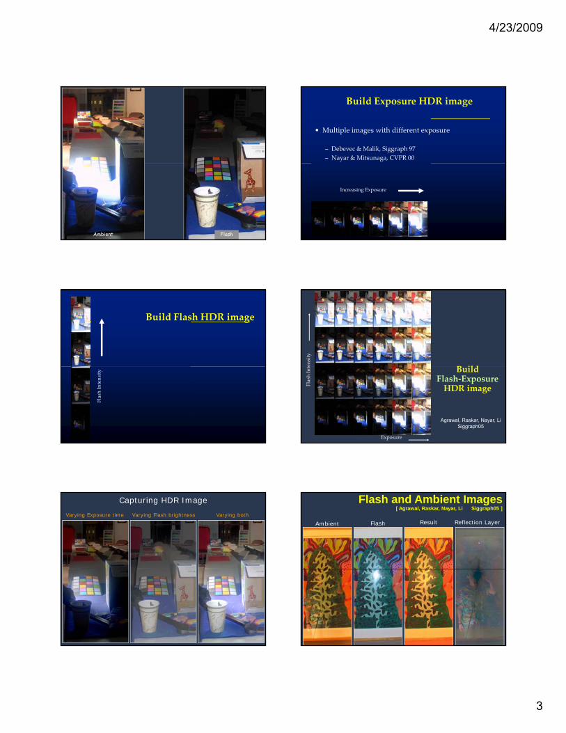
FlashAmbient
Build Exposure HDR image
• Multiple images with different exposure
– Debevec & Malik, Siggraph 97– Nayar & Mitsunaga, CVPR 00
Increasing Exposure
Build Flash HDR image
Flash Intensity B ilden
sity
Build Flash‐ExposureHDR image
Exposure
Flash Inte
Agrawal, Raskar, Nayar, LiSiggraph05
Ramesh Raskar, Computational Illumination
Varying Exposure time Varying Flash brightness Varying both
Capturing HDR Image
Flash Result Reflection LayerAmbient
Flash and Ambient Images[ Agrawal, Raskar, Nayar, Li Siggraph05 ]

4/23/2009
4
Intensity Gradient Vectors in Flash and Ambient Images
Same gradient vector direction
Flash Gradient Vector
Ambient Gradient Vector
Ambient Flash
No reflections
Reflection Ambient Gradient Vector
Different gradient vector direction
Ambient Flash
Flash Gradient Vector
With reflections
Residual Gradient Vector
Intensity Gradient Vector Projection
Result Gradient Vector
Ambient Flash Result Residual
Reflection Ambient Gradient Vector
Flash Gradient Vector
Ramesh Raskar, Computational Illumination
Computational Illumination:Computational Illumination:
•• Presence or Absence, Duration, BrightnessPresence or Absence, Duration, Brightness–– Flash/NoFlash/No--flashflash
•• Light color/wavelengthLight color/wavelength•• Light Light positionposition
–– MultiMulti--flash for depth edgesflash for depth edges–– Programmable dome (image reProgrammable dome (image re--lighting and matting)lighting and matting)
•• Spatial Spatial ModulationModulation–– Dual PhotographyDual Photography
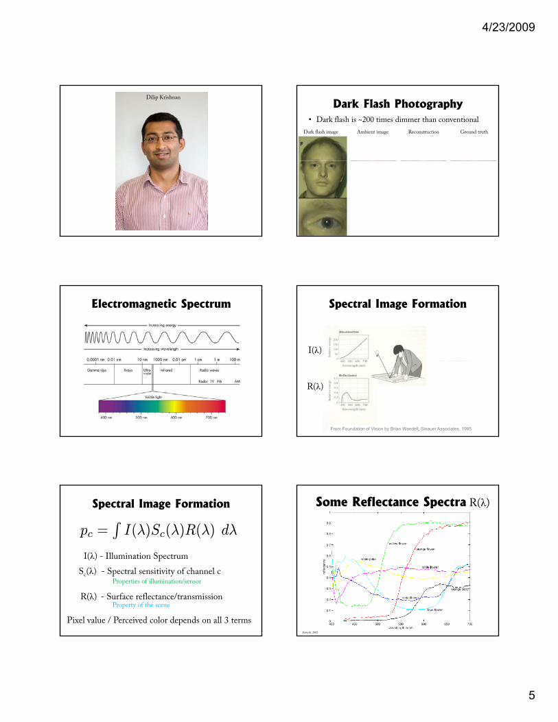
Dark Flash Photography
Dilip Krishnan and Rob Fergus
Dept. of Computer Science,Courant Institute,
New York University
4/23/2009
5
Dilip Krishnan
Dark Flash Photography• Dark flash is ~200 times dimmer than conventional
Dark flash image Ambient image Reconstruction Ground truth
Electromagnetic Spectrum Spectral Image Formation
I(λ) Sc(λ)
R(λ)
I(λ) R(λ)From Foundation of Vision by Brian Wandell, Sinauer Associates, 1995
Spectral Image Formation
pc =RI(λ)Sc(λ)R(λ) dλ
I(λ) - Illumination Spectrum p
R(λ) - Surface reflectance/transmission
Sc(λ) - Spectral sensitivity of channel c
Pixel value / Perceived color depends on all 3 terms
Property of the scene
Properties of illumination/sensor
Some Reflectance Spectra R(λ)
Forsyth, 2002
4/23/2009
6
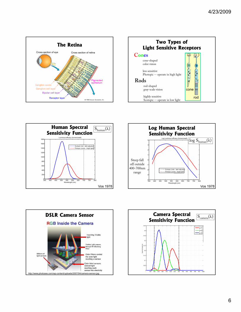
The RetinaCross-section of eye Cross section of retina
Ganglion cell layer
Bipolar cell layer
Receptor layer
Pigmentedepithelium
Ganglion axons
Two Types of Light Sensitive Receptors
Conescone-shapedcolor vision
cone
rod
less sensitivePhotopic -- operate in high light
Rodsrod-shapedgray-scale vision
highly sensitiveScotopic -- operate in low light
Human Spectral Sensitivity Function
1200
1400
1600
1800Luminous efficacy (lumens/watt)
Scotopic (rod - dark adjusted)Photopic (cones - bright light)
Shuman(λ)
Vos 1978
350 400 450 500 550 600 650 700 750 8000
200
400
600
800
1000
Wavelength (nm)
Log Human Spectral Sensitivity Function
1
2
3
4Log Luminous efficacy (lumens/watt)
log Shuman(λ)
Vos 1978
350 400 450 500 550 600 650 700 750 800-4
-3
-2
-1
0
Wavelength (nm)
Scotopic (rods - dark adjusted)Photopic (cones - bright light)
Steep falloff outside400-700nm
range
DSLR Camera Sensor
http://www.photoaxe.com/wp-content/uploads/2007/04/camera-sensor.jpg
0.3
0.35
0.4
0.45
j=1j=2j=3
Camera Spectral Sensitivity Function
Scamera(λ)
350 400 450 500 550 600 650 700 750 800 850 900 950 10000
0.05
0.1
0.15
0.2
0.25
Spec
tral
resp
onse
4/23/2009
7
0.3
0.35
0.4
0.45
j=1j=2j=3
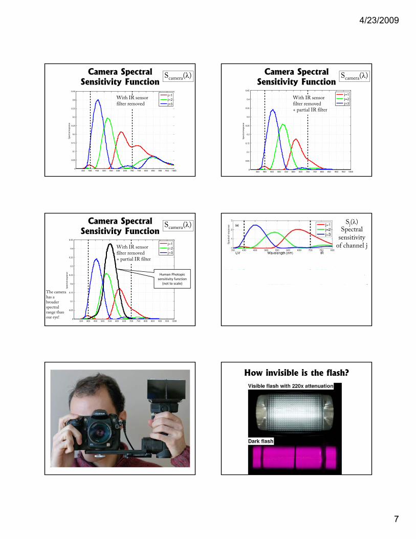
Camera Spectral Sensitivity Function
Scamera(λ)
With IR sensorfilter removed
350 400 450 500 550 600 650 700 750 800 850 900 950 10000
0.05
0.1
0.15
0.2
0.25
Spec
tral
resp
onse
0.3
0.35
0.4
0.45
j=1j=2j=3
Camera Spectral Sensitivity Function
Scamera(λ)
With IR sensorfilter removed + partial IR filter
350 400 450 500 550 600 650 700 750 800 850 900 950 10000
0.05
0.1
0.15
0.2
0.25
Spec
tral
resp
onse
0.3
0.35
0.4
0.45
j=1j=2j=3
Camera Spectral Sensitivity Function
Scamera(λ)
With IR sensorfilter removed + partial IR filter
350 400 450 500 550 600 650 700 750 800 850 900 950 10000
0.05
0.1
0.15
0.2
0.25
Spec
tral
resp
onse Human Photopic
sensitivity function(not to scale)
The camera has a broader spectral range than our eye!
I(λ)Flash
Sj(λ)Spectral
sensitivity of channel j
spectrum
Signal ofwhite paper
How invisible is the flash?
4/23/2009
8
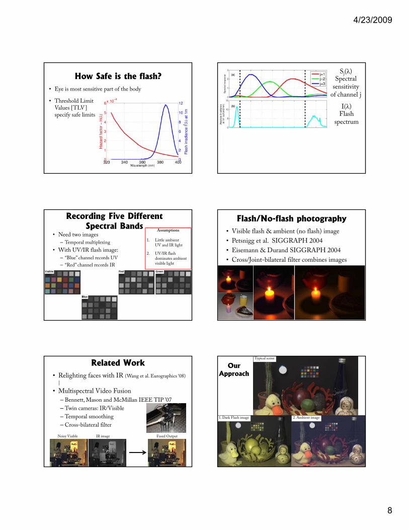
How Safe is the flash?• Eye is most sensitive part of the body
• Threshold Limit Values [TLV] specify safe limitsp y
• 115,000 flashes in8 hr period
• Equivalent to being outside for 1/100th second
I(λ)Flash
Sj(λ)Spectral
sensitivity of channel j
spectrum
Signal ofwhite paper
(R(λ) =1)
I(λ) Sj(λ) R(λ)
Recording Five Different Spectral Bands
• Need two images
– Temporal multiplexing
• With UV/IR flash image:
– “Blue” channel records UV
“Red” channel records IR
Assumptions
1. Little ambient UV and IR light
2. UV/IR flash dominates ambient visible light– Red channel records IR g
Flash/No-flash photography• Visible flash & ambient (no flash) image
• Petsnigg et al. SIGGRAPH 2004
• Eisemann & Durand SIGGRAPH 2004
• Cross/Joint-bilateral filter combines images
Related Work• Relighting faces with IR (Wang et al. Eurographics ‘08)
|
• Multispectral Video Fusion
– Bennett, Mason and McMillan IEEE TIP ’07
– Twin cameras: IR/Visible
– Temporal smoothing
– Cross-bilateral filter
Noisy Visible IR image Fused Output
Typical scene
OurApproach
1. Dark Flash image 2. Ambient image
4/23/2009
9
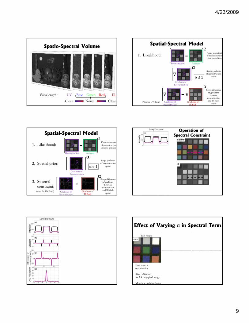
Spatio-Spectral Volume
Wavelength : UV Blue Green Red IR
NoisyClean Clean
Spatial-Spectral Model
1. Likelihood: -2
Ambient
αReconstruction
Keeps intensities of reconstruction close to ambient
Keeps gradients
2. Spatial prior:
3. Spectral constraint:
Gradients of Reconstruction
Gradients of Reconstruction
α
-
p gof reconstruction
sparse
Gradients of IR flash
(Also for UV flash)
Keeps difference of gradients
between reconstruction and IR flash
sparse
α ≤ 1
Spatial-Spectral Model
1. Likelihood: -2
Ambient
αReconstruction
Keeps intensities of reconstruction close to ambient
Keeps gradients
2. Spatial prior:
3. Spectral constraint:
Gradients of Reconstruction α
-
p gof reconstruction
sparse
Gradients of IR flash
(Also for UV flash)
Keeps difference of gradients
between reconstruction and IR flash
sparse
α ≤ 1
Gradients of Reconstruction
Operation of Spectral Constraint
α=0.7 α=1 α=2
Effect of Varying α in Spectral Term
Best results Acceptable results Unacceptable results
Implies that spectral reflectances are the same
in UV/IR and visible
NOT TRUE
Non-convexoptimization
Slow: ~20minsfor 1.4 megapixel image
Models actual distribution
Convex optimization
Fast: ~2 mins in Matlabfor 1.4 megapixel image
Can be easily be implemented on GPU
4/23/2009
10
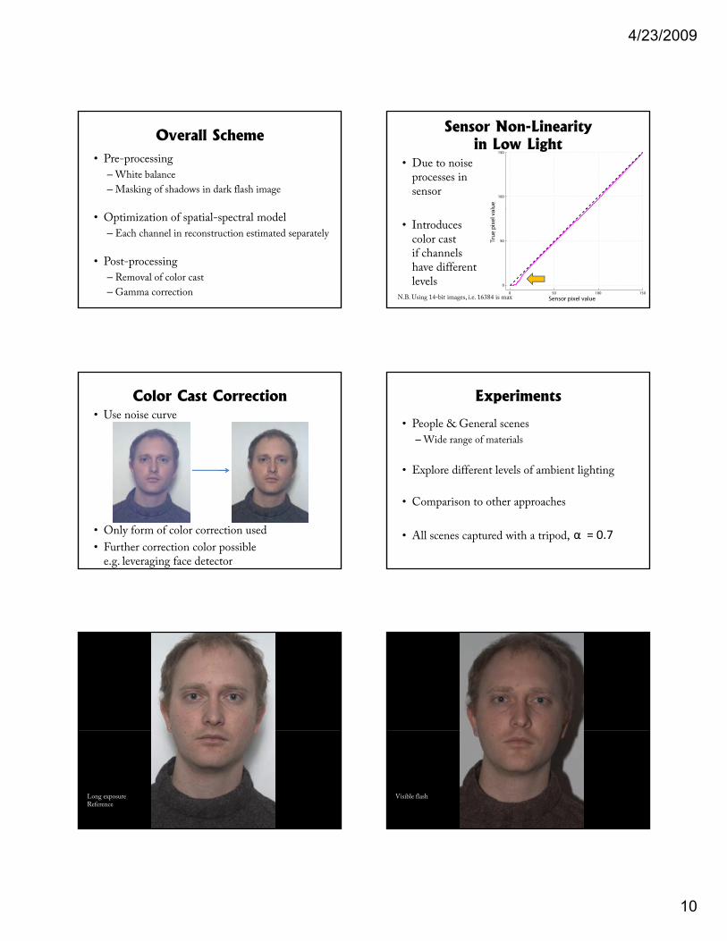
Overall Scheme• Pre-processing
– White balance
– Masking of shadows in dark flash image
• Optimization of spatial-spectral model
– Each channel in reconstruction estimated separately
• Post-processing
– Removal of color cast
– Gamma correction
Sensor Non-Linearity in Low Light
• Due to noiseprocesses in sensor
100
150
lue
• Introducescolor castif channelshave differentlevels
0 50 100 150
0
50
Sensor pixel value
True
pix
el v
a
N.B. Using 14-bit images, i.e. 16384 is max
• Use noise curve
Color Cast Correction
• Only form of color correction used
• Further correction color possiblee.g. leveraging face detector
Experiments
• People & General scenes
– Wide range of materials
• Explore different levels of ambient lighting• Explore different levels of ambient lighting
• Comparison to other approaches
• All scenes captured with a tripod, α = 0.7
Long exposureReference
Visible flash
4/23/2009
11
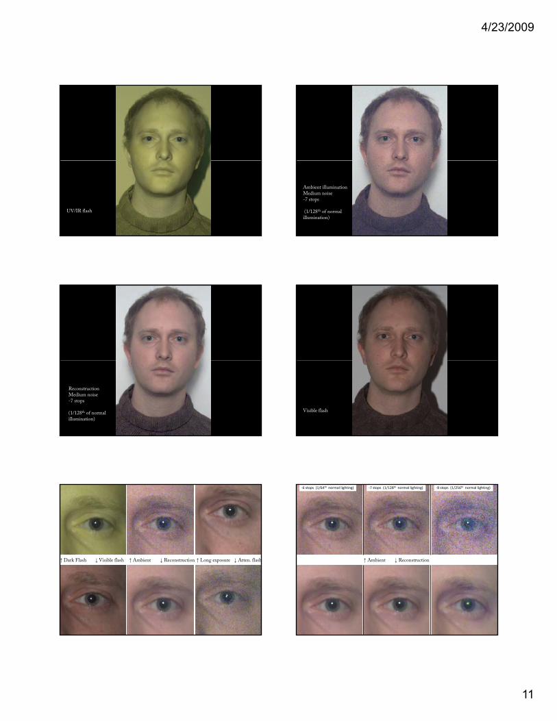
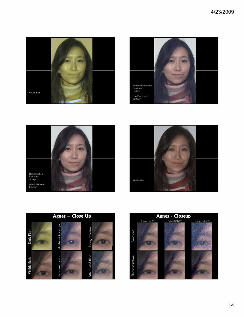
UV/IR flash
Ambient illuminationMedium noise-7 stops
(1/128th of normalillumination)
ReconstructionMedium noise-7 stops
(1/128th of normalillumination)
Visible flash
↑ Dark Flash ↓ Visible flash ↑ Ambient ↓ Reconstruction ↑ Long exposure ↓ Atten flash
‐7 stops (1/128th normal exposure)
↑ Dark Flash ↓ Visible flash ↑ Ambient ↓ Reconstruction ↑ Long exposure ↓ Atten. flash ↑ Ambient ↓ Reconstruction
‐7 stops (1/128th normal lighting) ‐8 stops (1/256th normal lighting)‐6 stops (1/64th normal lighting)
↑ Ambient ↓ Reconstruction
4/23/2009
12
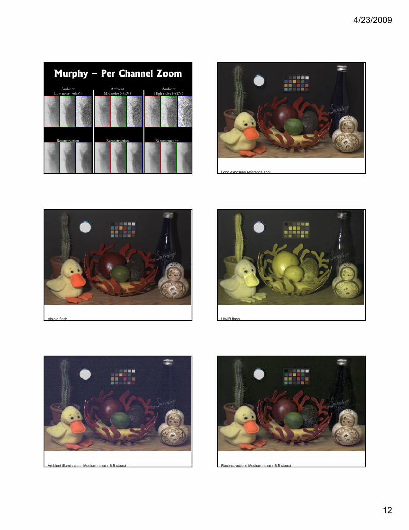
AmbientLow noise (-6EV)
AmbientMid noise (-7EV)
AmbientHigh noise (-8EV)
Murphy – Per Channel Zoom
ReconstructionReconstructionReconstruction
Long exposure reference shot
Visible flash UV/IR flash
Ambient illumination: Medium noise (-6.5 stops) Reconstruction: Medium noise (-6.5 stops)
4/23/2009
13
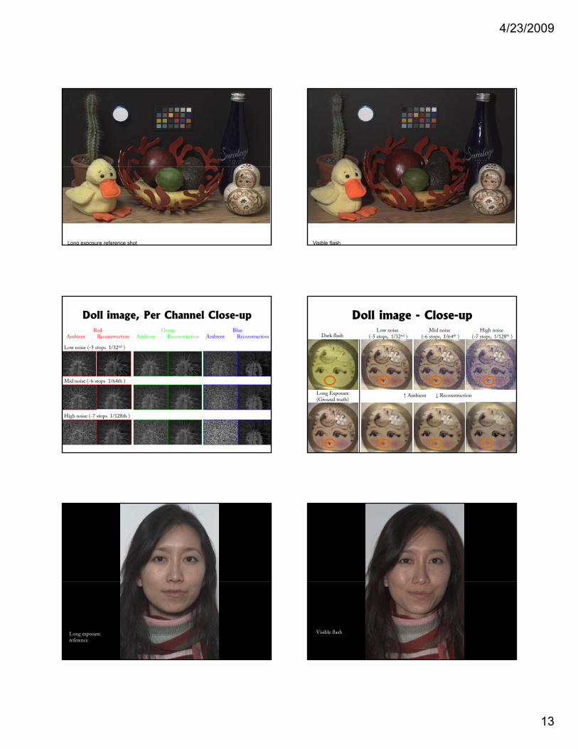
Long exposure reference shot Visible flash
Doll image, Per Channel Close-up
Low noise (-5 stops 1/32nd )
RedAmbient Reconstruction
GreenAmbient Reconstruction
BlueAmbient Reconstruction
Mid noise (-6 stops 1/64th )
High noise (-7 stops 1/128th )
Doll image - Close-upLow noise
(-5 stops, 1/32nd )Mid noise
(-6 stops, 1/64th )High noise
(-7 stops, 1/128th )Dark flash
Long Exposure(Ground truth)
↑ Ambient ↓ Reconstruction
Long exposurereference
Visible flash
4/23/2009
14
UV/IR flash
Ambient illuminationLow noise-6 stops
(1/64th of normallighting)
ReconstructionLow noise-6 stops
(1/64th of normallighting)
Visible flash
Agnes – Close Up
mbie
nt
(-7
stop
s)
Dar
k F
lash
Lon
g ex
pos
ure
Am
Rec
onst
ruct
ion
Vis
ible
fla
sh
LA
tten
uat
ed f
lash
-6 stops (1/64th) -7 stops (1/128th) -8 stops (1/256th)
Am
bie
nt
Agnes - Closeup
Rec
onst
ruct
ion
4/23/2009
15
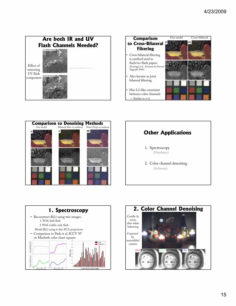
Effect ofi
Are both IR and UV Flash Channels Needed?
Effect ofremovingIR flash
component
removingUV flash
component
Comparisonto Cross-Bilateral
Filtering• Cross bilateral filtering
is method used in flash/no-flash papers (Petsnigg et al. , Eiseman & Durand
Our model Cross-bilateral
Siggraph 2004)
• Also known as joint bilateral filtering
• Has L2-like constraintbetween color channels
– Similar to α =2
Comparison to Denoising MethodsOur model Bilateral filter on ambient Noise Ninja on ambient
Other Applications
1. Spectroscopy(Hardware)(Hardware)
2. Color channel denoising
(Software)
1. Spectroscopy• Reconstruct R(λ) using two images:
1. With dark flash
2. With visible-only flash
Model R(λ) using 6-dim PCA projections
• Comparison to Park et al. ICCV ’07 on Macbeth color chart squareson Macbeth color chart squares
Candle-litscene,
after whitebalancing
Captured by
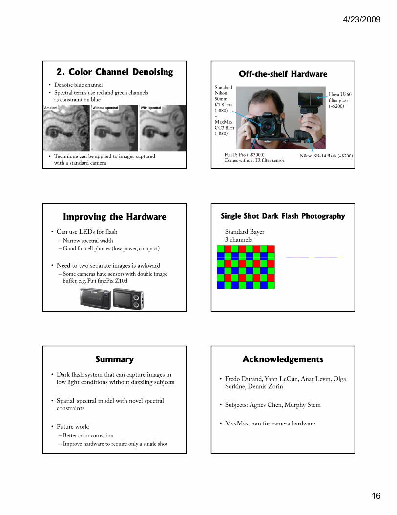
2. Color Channel Denoising
Red Green Blue
by unmodified
camera
4/23/2009
16
2. Color Channel Denoising• Denoise blue channel
• Spectral terms use red and green channels as constraint on blue
• Technique can be applied to images captured with a standard camera
Off-the-shelf HardwareStandardNikon 50mm f/1.8 lens(~$80)
Hoya U360 filter glass (~$200)
Fuji IS Pro (~$3000)Comes without IR filter sensor
Nikon SB-14 flash (~$200)
+MaxMaxCC3 filter(~$50)
Improving the Hardware
• Can use LEDs for flash
– Narrow spectral width
– Good for cell phones (low power, compact)
• Need to two separate images is awkward
– Some cameras have sensors with double image buffer, e.g. Fuji finePix Z10d
Single Shot Dark Flash Photography
Standard Bayer Dark Flash Bayer3 channels 5 channels
IR narrow band-pass filter @ ~750nm
UV narrow band-pass filter @ ~370nm
Summary
• Dark flash system that can capture images in low light conditions without dazzling subjects
• Spatial spectral model with novel spectral• Spatial-spectral model with novel spectral constraints
• Future work:
– Better color correction
– Improve hardware to require only a single shot
Acknowledgements
• Fredo Durand, Yann LeCun, Anat Levin, Olga Sorkine, Dennis Zorin
• Subjects: Agnes Chen, Murphy Stein
• MaxMax.com for camera hardware
4/23/2009
17
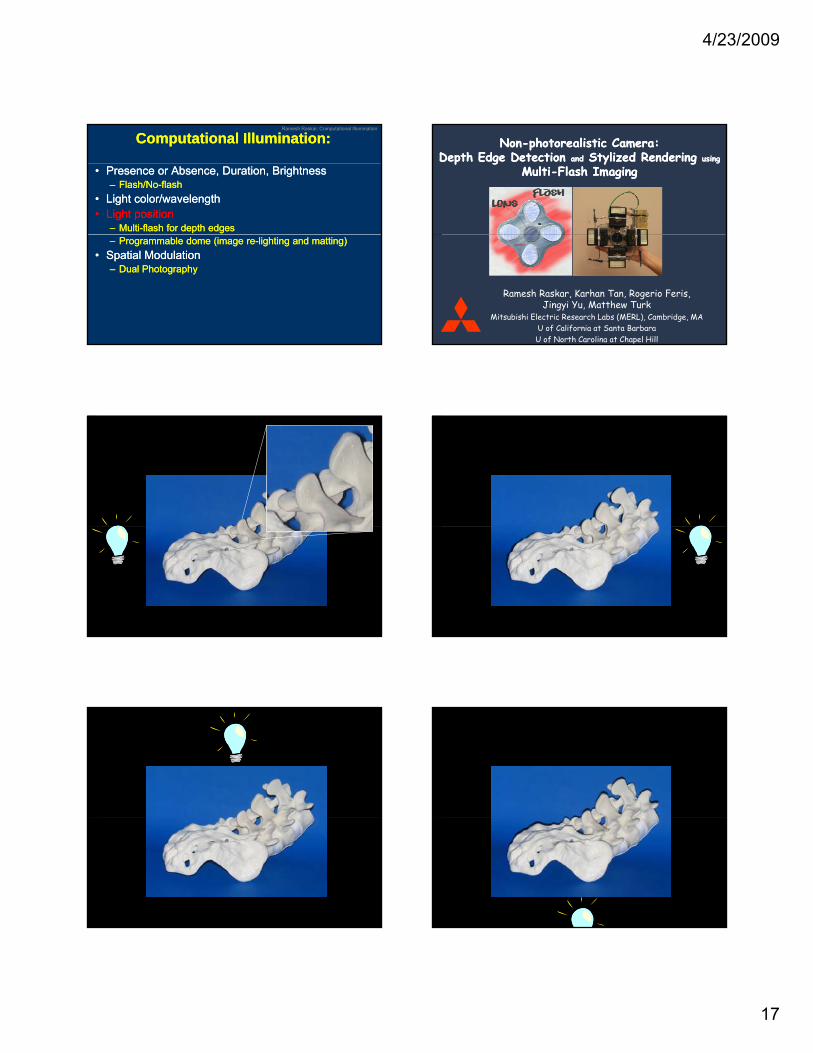
Ramesh Raskar, Computational Illumination
Computational Illumination:Computational Illumination:
•• Presence or Absence, Duration, BrightnessPresence or Absence, Duration, Brightness–– Flash/NoFlash/No--flashflash
•• Light color/wavelengthLight color/wavelength•• Light Light positionposition
–– MultiMulti--flash for depth edgesflash for depth edges–– Programmable dome (image reProgrammable dome (image re--lighting and matting)lighting and matting)
•• Spatial Spatial ModulationModulation–– Dual PhotographyDual Photography
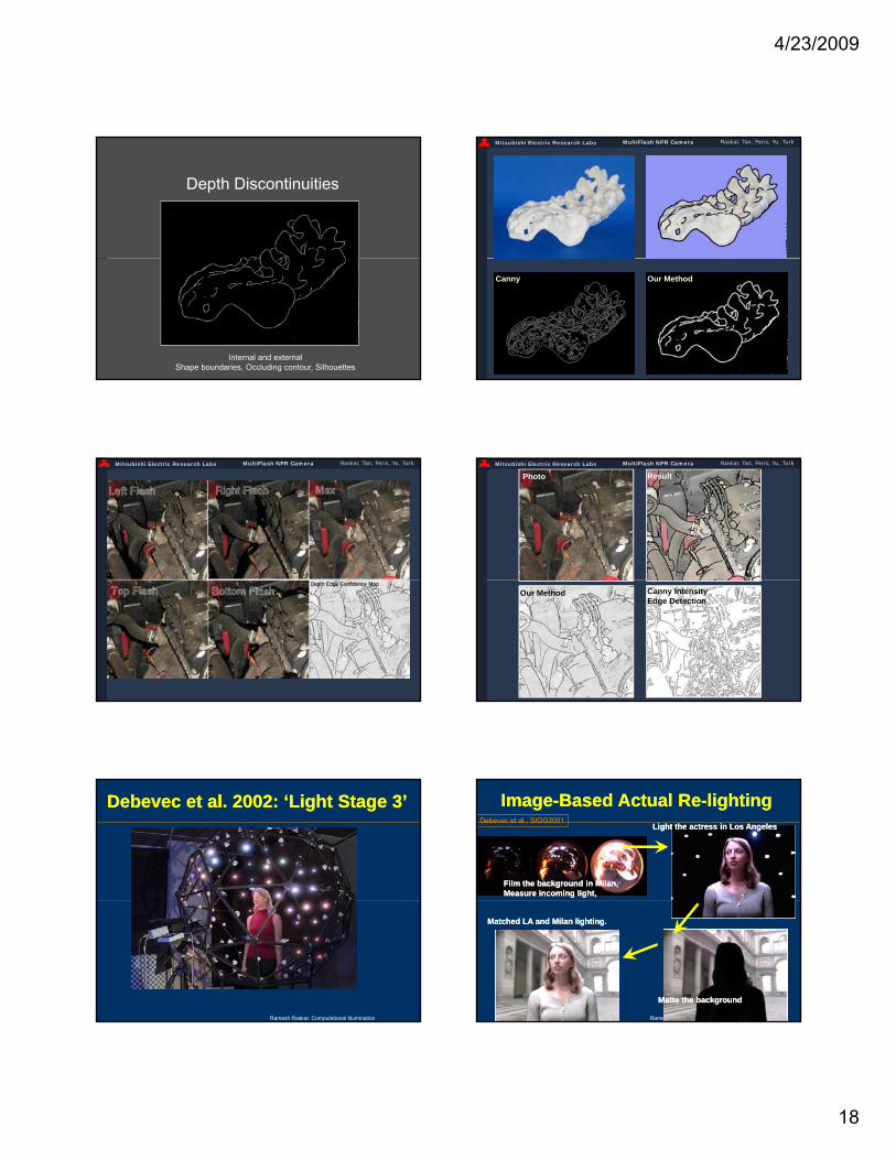
Mitsubishi Electric Research Labs Raskar, Tan, Feris, Yu, TurkMultiFlash NPR Camera
NonNon--photorealistic Camera: photorealistic Camera: Depth Edge Detection Depth Edge Detection andand Stylized Rendering Stylized Rendering usingusing
MultiMulti--Flash ImagingFlash Imaging
Ramesh Raskar, Karhan Tan, Rogerio Feris, Jingyi Yu, Matthew Turk
Mitsubishi Electric Research Labs (MERL), Cambridge, MAU of California at Santa BarbaraU of North Carolina at Chapel Hill
Mitsubishi Electric Research Labs Raskar, Tan, Feris, Yu, TurkMultiFlash NPR Camera Mitsubishi Electric Research Labs Raskar, Tan, Feris, Yu, TurkMultiFlash NPR Camera
Mitsubishi Electric Research Labs Raskar, Tan, Feris, Yu, TurkMultiFlash NPR Camera Mitsubishi Electric Research Labs Raskar, Tan, Feris, Yu, TurkMultiFlash NPR Camera
4/23/2009
18
Mitsubishi Electric Research Labs Raskar, Tan, Feris, Yu, TurkMultiFlash NPR Camera
Depth Discontinuities
Internal and externalShape boundaries, Occluding contour, Silhouettes
Mitsubishi Electric Research Labs Raskar, Tan, Feris, Yu, TurkMultiFlash NPR Camera
Our MethodCanny
Mitsubishi Electric Research Labs Raskar, Tan, Feris, Yu, TurkMultiFlash NPR Camera Mitsubishi Electric Research Labs Raskar, Tan, Feris, Yu, TurkMultiFlash NPR Camera
Photo Result
Canny Intensity Edge Detection
Our Method
Debevec et al. 2002: ‘Light Stage 3’Debevec et al. 2002: ‘Light Stage 3’
Ramesh Raskar, Computational Illumination
ImageImage--Based Actual ReBased Actual Re--lightinglighting
Film the background in Milan,Film the background in Milan,Measure incoming light,Measure incoming light,
Light the actress in Los AngelesLight the actress in Los AngelesDebevec et al., SIGG2001
Ramesh Raskar, Computational Illumination
Matte the backgroundMatte the background
Matched LA and Milan lighting.Matched LA and Milan lighting.
4/23/2009
19
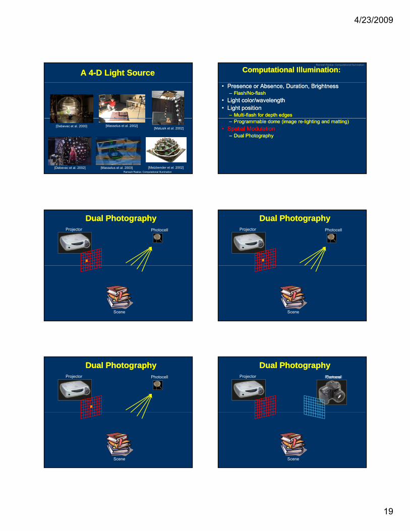
A 4A 4--D Light SourceD Light Source
Ramesh Raskar, Computational Illumination[Debevec et al. 2002]
[Debevec et al. 2000] [Masselus et al. 2002]
[Masselus et al. 2003] [Malzbender et al. 2002]
[Matusik et al. 2002]
Ramesh Raskar, Computational Illumination
Computational Illumination:Computational Illumination:
•• Presence or Absence, Duration, BrightnessPresence or Absence, Duration, Brightness–– Flash/NoFlash/No--flashflash
•• Light color/wavelengthLight color/wavelength•• Light Light positionposition
–– MultiMulti--flash for depth edgesflash for depth edges–– Programmable dome (image reProgrammable dome (image re--lighting and matting)lighting and matting)
•• Spatial Spatial ModulationModulation–– Dual PhotographyDual Photography
Dual PhotographyDual PhotographyPhotocellProjector
Scene
Dual PhotographyDual PhotographyPhotocellProjector
Scene
Dual PhotographyDual PhotographyPhotocellProjector
Scene
Dual PhotographyDual PhotographyPhotocellProjector Camera
Scene
4/23/2009
20
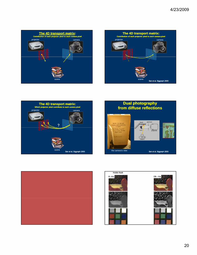
camera
The 4D transport matrixThe 4D transport matrix::Contribution of each projector pixel to each camera pixelContribution of each projector pixel to each camera pixel
projector
scene
camera
The 4D transport matrix:The 4D transport matrix:Contribution of each projector pixel to each camera pixelContribution of each projector pixel to each camera pixel
projector
sceneSen et al, Siggraph 2005Sen et al, Siggraph 2005
camera
The 4D transport matrix:The 4D transport matrix:Which projector pixel contribute to each camera pixelWhich projector pixel contribute to each camera pixel
projector
??
sceneSen et al, Siggraph 2005Sen et al, Siggraph 2005
Dual photographyDual photographyfrom diffuse reflectionsfrom diffuse reflections
the camera’s view Sen et al, Siggraph 2005Sen et al, Siggraph 2005
4/23/2009
21
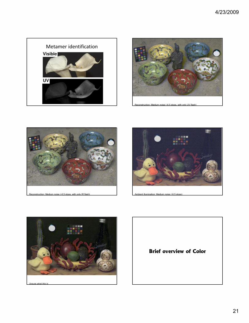
Metamer identification
Reconstruction: Medium noise (-6.5 stops, with only UV flash)
Reconstruction: Medium noise (-6.5 stops, with only IR flash) Ambient illumination: Medium noise (-6.5 stops)
Unsure what this is
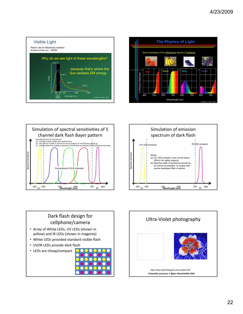
Brief overview of ColorBrief overview of Color
4/23/2009
22
Why do we see light of these wavelengths?
.
10000 C
…because that’s where the
Visible LightPlank’s law for Blackbody radiationSurface of the sun: ~5800K
© Stephen E. Palmer, 2002
0 1000 2000 3000
Ene
rgy
Wavelength (nm)
400 700
700 C
2000 C
5000 C
VisibleRegion
…because that s where theSun radiates EM energy
The Physics of Light
Some examples of the reflectance spectra of surfaces
Wavelength (nm)
% P
hoto
ns R
efle
cted
Red
400 700
Yellow
400 700
Blue
400 700
Purple
400 700
© Stephen E. Palmer, 2002
Simulation of spectral sensitivities of 5 channel dark flash Bayer pattern
Note that UV and IR channels are:(a) Only just outside visible (blue dashed lines)(b) Very narrow in width to prevent too much ambient UV and IR being picked up(c) Closely matched to emission spectrum of UV/IR flash provided by UV/IR LEDs (see next slide)
sitiv
ity
350 400 700 800500 600UV IR
Conventional R,G,B channels
Wavelength (nm)
Spec
tral s
ens
Simulation of emission spectrum of dark flash
ssio
n
UV LED emission IR LED emission
Notes:( )
350 400 700 800500 600UV IRWavelength (nm)
Spec
tral e
mis (a) UV LED emission must not be below
350nm for safety reasons(b) Spectral width of emissions should be
as narrow as possible, to couple withnarrow bandpass filter of sensor
Dark flash design for cellphone/camera
• Array of White LEDs, UV LEDs (shown in yellow) and IR LEDs (shown in magenta)
• White LEDs provided standard visible flash
/ id d k fl h• UV/IR LEDs provide dark flash
• LEDs are cheap/compact
Ultra‐Violet photography
The image part with relationship ID rId2 was not found in the file.
http://www.naturfotograf.com/uvstart.html
Potentilla anserina © Bjørn Rørslett/NN 2001
4/23/2009
23
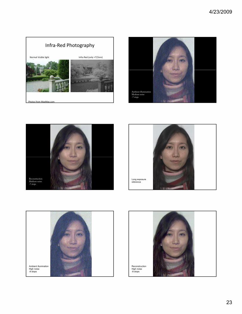
Infra‐Red Photography
Normal Visible light image
Infra Red (only >715nm)
Photos from MaxMax.com
Ambient illuminationMedium noise-7 stops
ReconstructionMedium noise-7 stops
Long exposurereference
Ambient illuminationHigh noise-8 stops
ReconstructionHigh noise-8 stops
4/23/2009
24
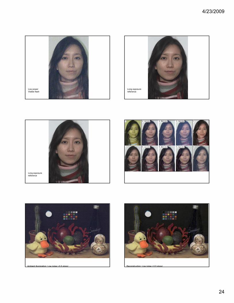
Low powerVisible flash
Long exposurereference
Long exposurereference
Ambient illumination: Low noise (-5.5 stops) Reconstruction: Low noise (-5.5 stops)
4/23/2009
25
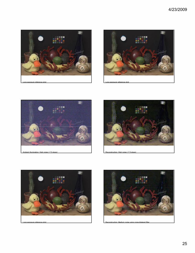
Long exposure reference shot Long exposure reference shot
Ambient illumination: High noise (-7.5 stops) Reconstruction: High noise (-7.5 stops)
Long exposure reference shot Reconstruction: Medium noise using cross-bilateral filter
4/23/2009
26
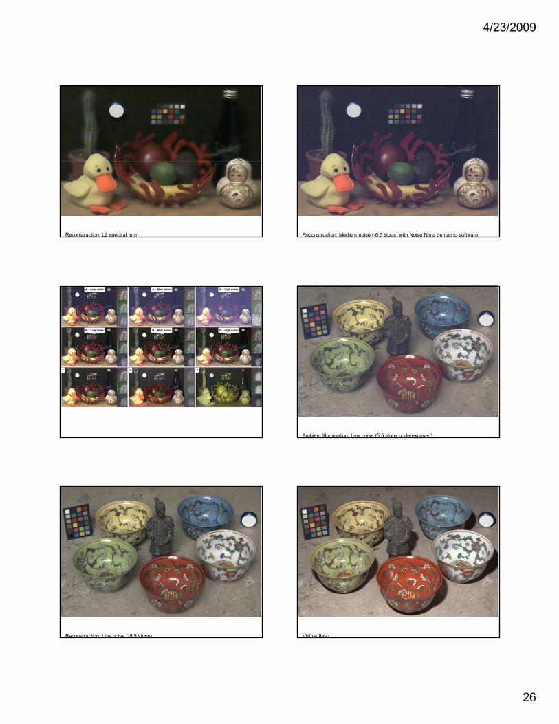
Reconstruction: L2 spectral term Reconstruction: Medium noise (-6.5 stops) with Noise Ninja denosing software
Ambient Illumination: Low noise (5.5 stops underexposed)
Reconstruction: Low noise (-5.5 stops) Visible flash
4/23/2009
27
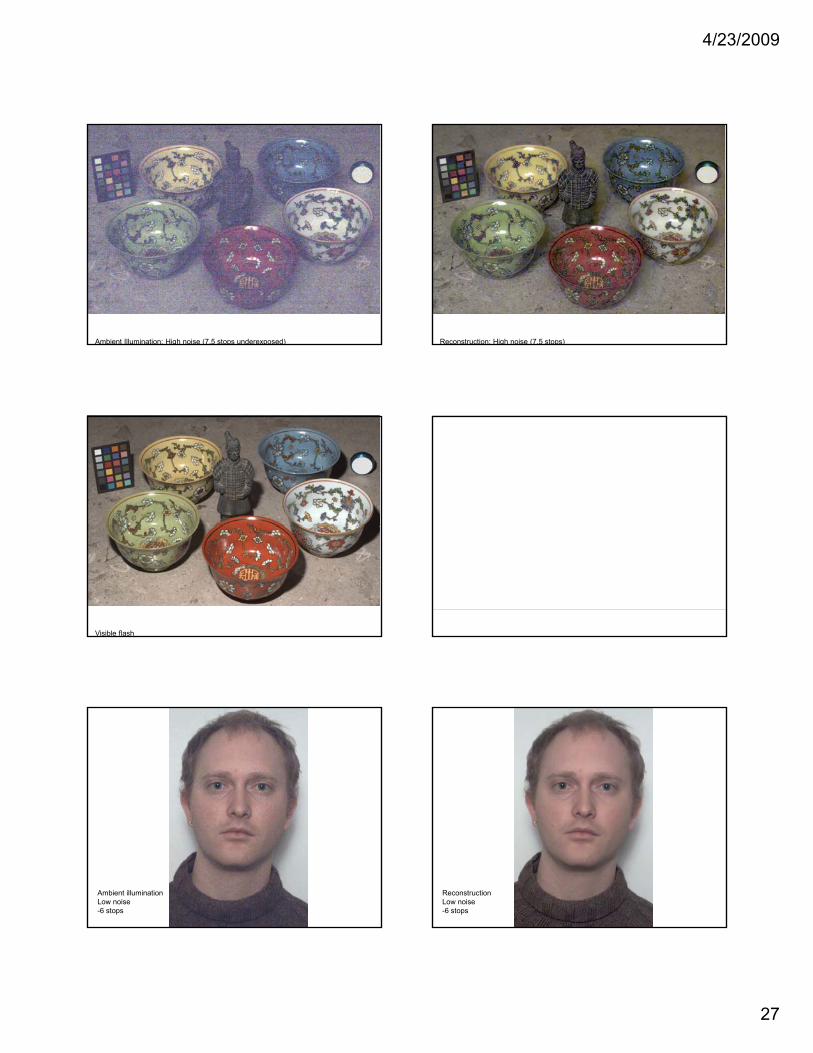
Ambient Illumination: High noise (7.5 stops underexposed) Reconstruction: High noise (7.5 stops)
Visible flash
The image part with relationship ID rId2 was not found in the file.
Ambient illuminationLow noise-6 stops
ReconstructionLow noise-6 stops
4/23/2009
28
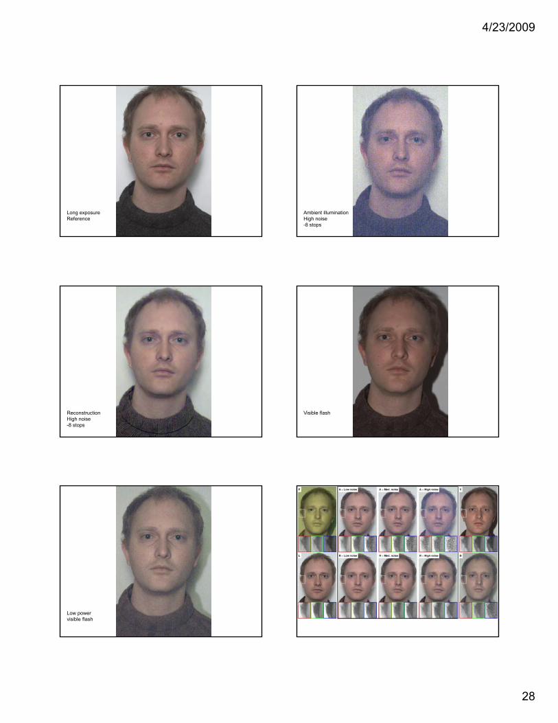
Long exposureReference
Ambient illuminationHigh noise-8 stops
ReconstructionHigh noise-8 stops
Visible flash
Low powervisible flash
4/23/2009
29
http://farm4 static flickr com/3130/2747940520 d652ce1e7a jp
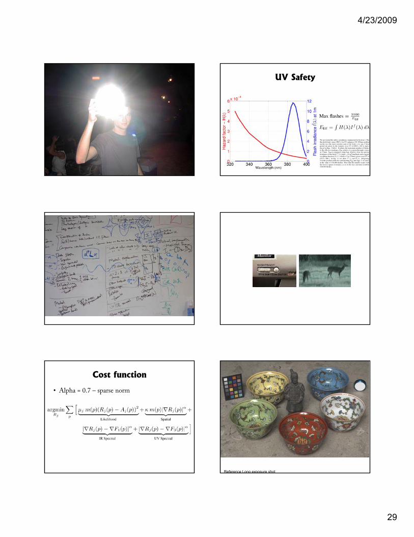
UV Safety
Cost function
• Alpha = 0.7 – sparse norm
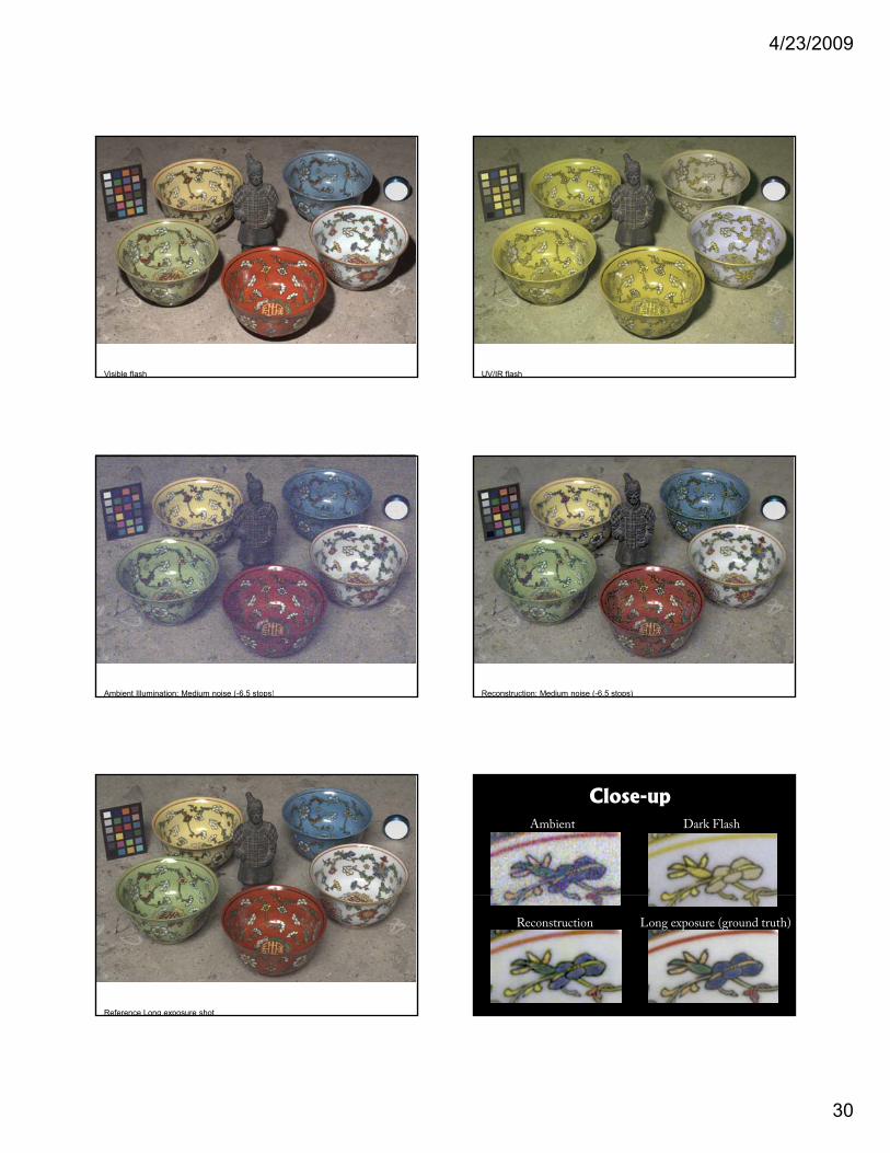
Reference Long exposure shot
4/23/2009
30
Visible flash UV/IR flash
Ambient Illumination: Medium noise (-6.5 stops) Reconstruction: Medium noise (-6.5 stops)
Reference Long exposure shot
Ambient Dark Flash
Close-up
Long exposure (ground truth)Reconstruction
4/23/2009
31
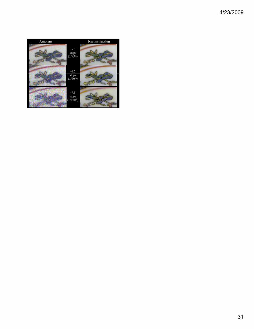
Ambient Reconstruction
-5.5stops
(1/45th)
-6.5stops
(1/90th)
-7.5stops
(1/180th)