
SIEP S800000 46B
337
Rotational Motor MECHATROLINK-II Communications Reference SGDV SERVOPACK SGMJV/SGMAV/SGMPS/SGMGV/SGMSV/SGMCS Servomotors MANUAL NO. SIEP S800000 46B Σ -V Series AC Servo Drives Outline Wiring and Connection Operation Adjustments Utility Functions (Fn) Monitor Modes (Un) Fully-closed Loop Control Troubleshooting Appendix Panel Display and Operation of Digital Operator 1 2 3 4 5 6 7 8 9 10 USER'S MANUAL Design and Maintenance
-
Upload
daniel-moran-hernandez -
Category
Documents
-
view
72 -
download
8
Transcript of SIEP S800000 46B
Rotational MotorMECHATROLINK-II Communications ReferenceSGDV SERVOPACKSGMJV/SGMAV/SGMPS/SGMGV/SGMSV/SGMCS Servomotors
MANUAL NO. SIEP S800000 46B
Σ-V SeriesAC Servo Drives
Outline
Wiring and Connection
Operation
Adjustments
Utility Functions (Fn)
Monitor Modes (Un)
Fully-closed Loop Control
Troubleshooting
Appendix
Panel Display and Operation of Digital Operator
1
2
3
4
5
6
7
8
9
10
USER'S MANUAL Design and Maintenance

Copyright © 2007 YASKAWA ELECTRIC CORPORATION
All rights reserved. No part of this publication may be reproduced, stored in a retrieval system, or transmitted, in any form, or by any means, mechanical, electronic, photocopying, recording, or otherwise, without the prior written permission of Yaskawa. No patent liability is assumed with respect to the use of the information contained herein. Moreover, because Yaskawa is con-stantly striving to improve its high-quality products, the information contained in this manual is subject to change without notice. Every precaution has been taken in the preparation of this manual. Nevertheless, Yaskawa assumes no responsibility for errors or omissions. Neither is any liability assumed for damages resulting from the use of the information contained in this publication.
iii
About this Manual
This manual describes informations required for designing, and maintaining Σ-V Series SERVOPACKs.
Be sure to refer to this manual and perform design and maintenance to select devices correctly.
Keep this manual in a location where it can be accessed for reference whenever required.
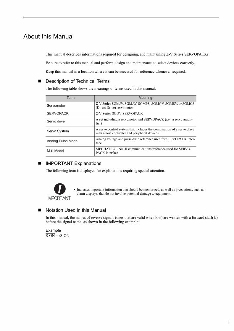
Description of Technical TermsThe following table shows the meanings of terms used in this manual.
IMPORTANT ExplanationsThe following icon is displayed for explanations requiring special attention.
Notation Used in this ManualIn this manual, the names of reverse signals (ones that are valid when low) are written with a forward slash (/) before the signal name, as shown in the following example:
ExampleS-ON = /S-ON
Term Meaning
Servomotor Σ-V Series SGMJV, SGMAV, SGMPS, SGMGV, SGMSV, or SGMCS (Direct Drive) servomotor
SERVOPACK Σ-V Series SGDV SERVOPACK
Servo drive A set including a servomotor and SERVOPACK (i.e., a servo ampli-fier)
Servo System A servo control system that includes the combination of a servo drive with a host controller and peripheral devices
Analog Pulse Model Analog voltage and pulse-train reference used for SERVOPACK inter-face
M-II Model MECHATROLINK-II communications reference used for SERVO-PACK interface
• Indicates important information that should be memorized, as well as precautions, such as alarm displays, that do not involve potential damage to equipment.
iv
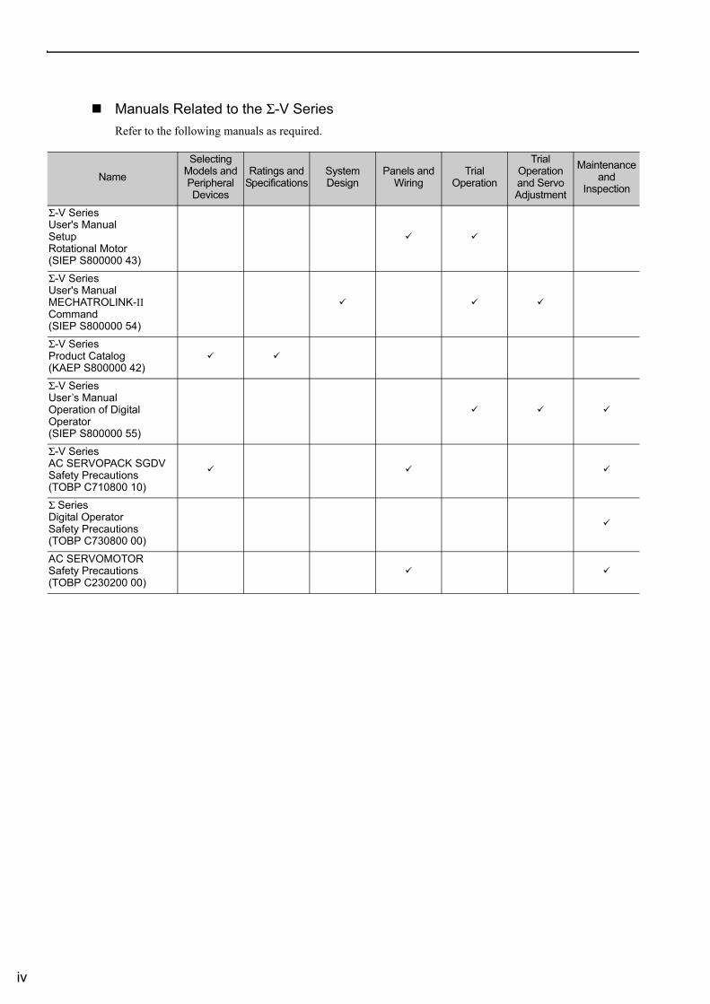
Manuals Related to the Σ-V SeriesRefer to the following manuals as required.
Name
Selecting Models and Peripheral Devices
Ratings and Specifications
System Design
Panels and Wiring
Trial Operation
Trial Operation and Servo Adjustment
Maintenance and
Inspection
Σ-V Series User's Manual SetupRotational Motor (SIEP S800000 43)
Σ-V Series User's Manual MECHATROLINK-IICommand(SIEP S800000 54)
Σ-V Series Product Catalog(KAEP S800000 42)
Σ-V Series User’s ManualOperation of Digital Operator(SIEP S800000 55)
Σ-V SeriesAC SERVOPACK SGDV Safety Precautions(TOBP C710800 10)
Σ SeriesDigital OperatorSafety Precautions(TOBP C730800 00)
AC SERVOMOTORSafety Precautions(TOBP C230200 00)
v
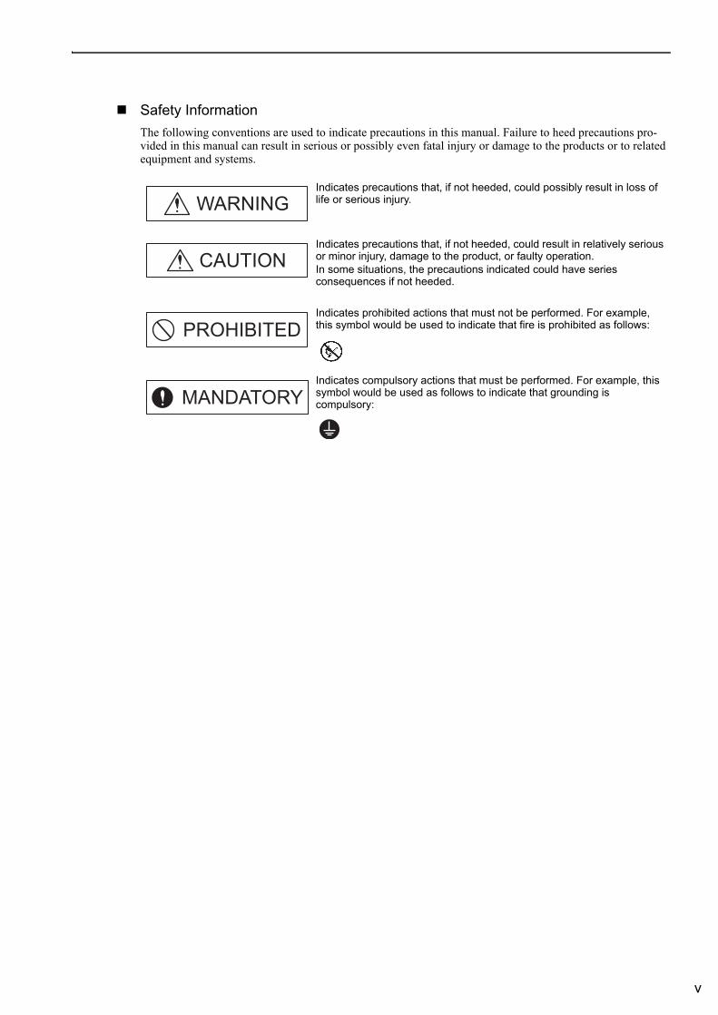
Safety InformationThe following conventions are used to indicate precautions in this manual. Failure to heed precautions pro-vided in this manual can result in serious or possibly even fatal injury or damage to the products or to related equipment and systems.
Indicates precautions that, if not heeded, could possibly result in loss of life or serious injury.
Indicates precautions that, if not heeded, could result in relatively serious or minor injury, damage to the product, or faulty operation.In some situations, the precautions indicated could have series consequences if not heeded.
Indicates prohibited actions that must not be performed. For example, this symbol would be used to indicate that fire is prohibited as follows:
Indicates compulsory actions that must be performed. For example, this symbol would be used as follows to indicate that grounding is compulsory:
WARNING
CAUTION
PROHIBITED
MANDATORY
vi
Safety Precautions
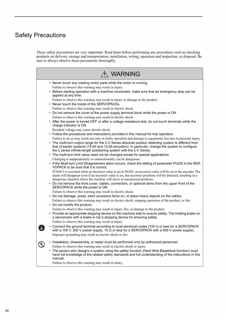
These safety precautions are very important. Read them before performing any procedures such as checking products on delivery, storage and transportation, installation, wiring, operation and inspection, or disposal. Be sure to always observe these precautions thoroughly.
WARNING• Never touch any rotating motor parts while the motor is running.
Failure to observe this warning may result in injury.• Before starting operation with a machine connected, make sure that an emergency stop can be
applied at any time.Failure to observe this warning may result in injury or damage to the product.
• Never touch the inside of the SERVOPACKs.Failure to observe this warning may result in electric shock.
• Do not remove the cover of the power supply terminal block while the power is ON.Failure to observe this warning may result in electric shock.
• After the power is turned OFF or after a voltage resistance test, do not touch terminals while the charge indicator is ON.Residual voltage may cause electric shock.
• Follow the procedures and instructions provided in this manual for trial operation. Failure to do so may result not only in faulty operation and damage to equipment, but also in personal injury.
• The multi-turn output range for the Σ-V Series absolute position detecting system is different from that of earlier systems (15-bit and 12-bit encoders). In particular, change the system to configure the Σ series infinite-length positioning system with the Σ-V Series.
• The multi-turn limit value need not be changed except for special applications.Changing it inappropriately or unintentionally can be dangerous.
• If the Multi-turn Limit Disagreement alarm occurs, check the setting of parameter Pn205 in the SER-VOPACK to be sure that it is correct.If Fn013 is executed when an incorrect value is set in Pn205, an incorrect value will be set in the encoder. The alarm will disappear even if an incorrect value is set, but incorrect positions will be detected, resulting in a dangerous situation where the machine will move to unexpected positions.
• Do not remove the front cover, cables, connectors, or optional items from the upper front of the SERVOPACK while the power is ON.Failure to observe this warning may result in electric shock.
• Do not damage, press, exert excessive force on, or place heavy objects on the cables. Failure to observe this warning may result in electric shock, stopping operation of the product, or fire.
• Do not modify the product.Failure to observe this warning may result in injury, fire, or damage to the product.
• Provide an appropriate stopping device on the machine side to ensure safety. The holding brake on a servomotor with a brake is not a stopping device for ensuring safety.Failure to observe this warning may result in injury.
• Connect the ground terminal according to local electrical codes (100 Ω or less for a SERVOPACK with a 100 V, 200 V power supply, 10 Ω or less for a SERVOPACK with a 400 V power supply).Improper grounding may result in electric shock or fire.
• Installation, disassembly, or repair must be performed only by authorized personnel.Failure to observe this warning may result in electric shock or injury.
• The person who designs a system using the safety function (Hard Wire Baseblock function) must have full knowledge of the related safety standards and full understanding of the instructions in this manual.Failure to observe this warning may result in injury.
vii
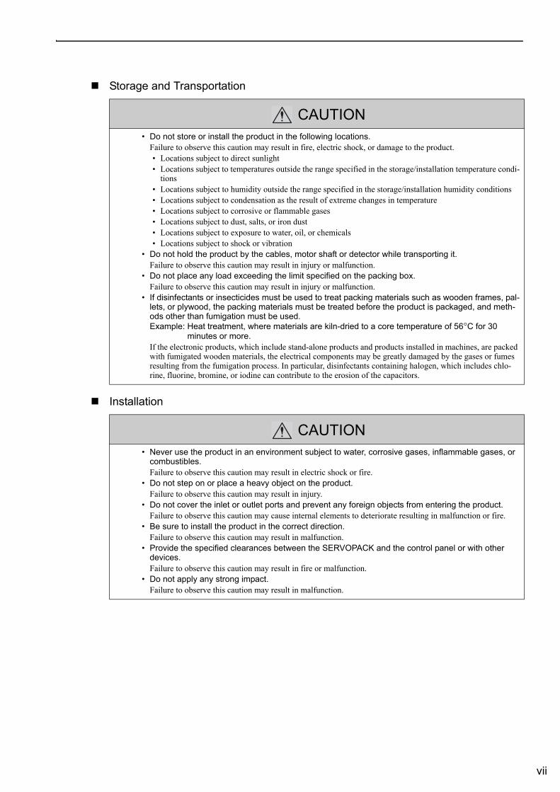
Storage and Transportation
Installation
CAUTION• Do not store or install the product in the following locations.
Failure to observe this caution may result in fire, electric shock, or damage to the product.• Locations subject to direct sunlight• Locations subject to temperatures outside the range specified in the storage/installation temperature condi-
tions• Locations subject to humidity outside the range specified in the storage/installation humidity conditions• Locations subject to condensation as the result of extreme changes in temperature• Locations subject to corrosive or flammable gases• Locations subject to dust, salts, or iron dust• Locations subject to exposure to water, oil, or chemicals• Locations subject to shock or vibration
• Do not hold the product by the cables, motor shaft or detector while transporting it.Failure to observe this caution may result in injury or malfunction.
• Do not place any load exceeding the limit specified on the packing box.Failure to observe this caution may result in injury or malfunction.
• If disinfectants or insecticides must be used to treat packing materials such as wooden frames, pal-lets, or plywood, the packing materials must be treated before the product is packaged, and meth-ods other than fumigation must be used.Example: Heat treatment, where materials are kiln-dried to a core temperature of 56°C for 30 minutes or more.If the electronic products, which include stand-alone products and products installed in machines, are packed with fumigated wooden materials, the electrical components may be greatly damaged by the gases or fumes resulting from the fumigation process. In particular, disinfectants containing halogen, which includes chlo-rine, fluorine, bromine, or iodine can contribute to the erosion of the capacitors.
CAUTION• Never use the product in an environment subject to water, corrosive gases, inflammable gases, or
combustibles.Failure to observe this caution may result in electric shock or fire.
• Do not step on or place a heavy object on the product.Failure to observe this caution may result in injury.
• Do not cover the inlet or outlet ports and prevent any foreign objects from entering the product.Failure to observe this caution may cause internal elements to deteriorate resulting in malfunction or fire.
• Be sure to install the product in the correct direction.Failure to observe this caution may result in malfunction.
• Provide the specified clearances between the SERVOPACK and the control panel or with other devices.Failure to observe this caution may result in fire or malfunction.
• Do not apply any strong impact.Failure to observe this caution may result in malfunction.
viii
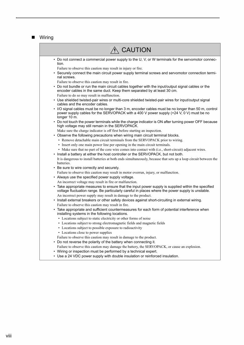
Wiring
CAUTION• Do not connect a commercial power supply to the U, V, or W terminals for the servomotor connec-
tion.Failure to observe this caution may result in injury or fire.
• Securely connect the main circuit power supply terminal screws and servomotor connection termi-nal screws.Failure to observe this caution may result in fire.
• Do not bundle or run the main circuit cables together with the input/output signal cables or the encoder cables in the same duct. Keep them separated by at least 30 cm.Failure to do so may result in malfunction.
• Use shielded twisted-pair wires or multi-core shielded twisted-pair wires for input/output signal cables and the encoder cables.
• I/O signal cables must be no longer than 3 m, encoder cables must be no longer than 50 m, control power supply cables for the SERVOPACK with a 400 V power supply (+24 V, 0 V) must be no longer 10 m.
• Do not touch the power terminals while the charge indicator is ON after turning power OFF because high voltage may still remain in the SERVOPACK.Make sure the charge indicator is off first before starting an inspection.
• Observe the following precautions when wiring main circuit terminal blocks.• Remove detachable main circuit terminals from the SERVOPACK prior to wiring.• Insert only one main power line per opening in the main circuit terminals.• Make sure that no part of the core wire comes into contact with (i.e., short-circuit) adjacent wires.
• Install a battery at either the host controller or the SERVOPACK, but not both.It is dangerous to install batteries at both ends simultaneously, because that sets up a loop circuit between the batteries.
• Be sure to wire correctly and securely.Failure to observe this caution may result in motor overrun, injury, or malfunction.
• Always use the specified power supply voltage.An incorrect voltage may result in fire or malfunction.
• Take appropriate measures to ensure that the input power supply is supplied within the specified voltage fluctuation range. Be particularly careful in places where the power supply is unstable.An incorrect power supply may result in damage to the product.
• Install external breakers or other safety devices against short-circuiting in external wiring.Failure to observe this caution may result in fire.
• Take appropriate and sufficient countermeasures for each form of potential interference when installing systems in the following locations.• Locations subject to static electricity or other forms of noise• Locations subject to strong electromagnetic fields and magnetic fields• Locations subject to possible exposure to radioactivity• Locations close to power supplies
Failure to observe this caution may result in damage to the product.• Do not reverse the polarity of the battery when connecting it.
Failure to observe this caution may damage the battery, the SERVOPACK, or cause an explosion.• Wiring or inspection must be performed by a technical expert.• Use a 24 VDC power supply with double insulation or reinforced insulation.
ix
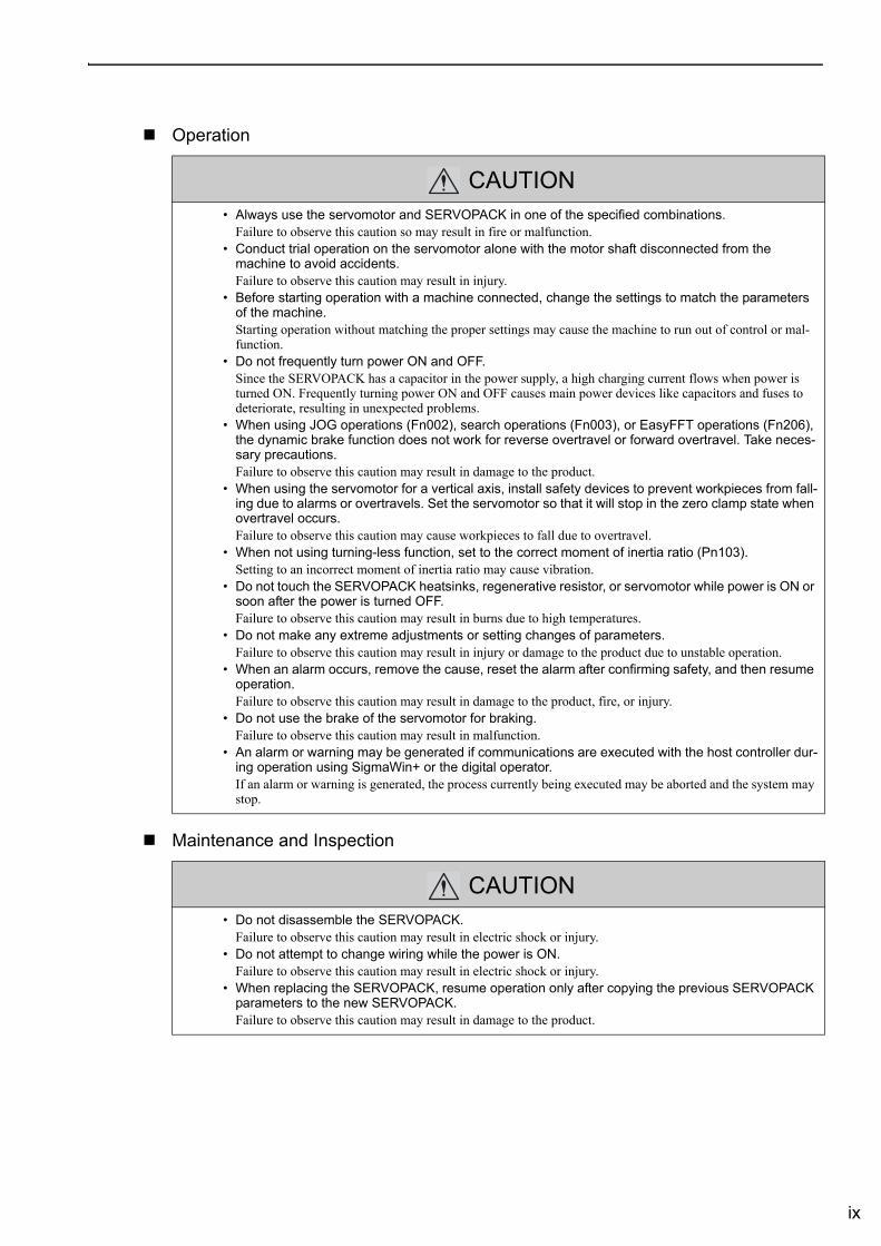
Operation
Maintenance and Inspection
CAUTION• Always use the servomotor and SERVOPACK in one of the specified combinations.
Failure to observe this caution so may result in fire or malfunction.• Conduct trial operation on the servomotor alone with the motor shaft disconnected from the
machine to avoid accidents.Failure to observe this caution may result in injury.
• Before starting operation with a machine connected, change the settings to match the parameters of the machine.Starting operation without matching the proper settings may cause the machine to run out of control or mal-function.
• Do not frequently turn power ON and OFF. Since the SERVOPACK has a capacitor in the power supply, a high charging current flows when power is turned ON. Frequently turning power ON and OFF causes main power devices like capacitors and fuses to deteriorate, resulting in unexpected problems.
• When using JOG operations (Fn002), search operations (Fn003), or EasyFFT operations (Fn206), the dynamic brake function does not work for reverse overtravel or forward overtravel. Take neces-sary precautions. Failure to observe this caution may result in damage to the product.
• When using the servomotor for a vertical axis, install safety devices to prevent workpieces from fall-ing due to alarms or overtravels. Set the servomotor so that it will stop in the zero clamp state when overtravel occurs.Failure to observe this caution may cause workpieces to fall due to overtravel.
• When not using turning-less function, set to the correct moment of inertia ratio (Pn103).Setting to an incorrect moment of inertia ratio may cause vibration.
• Do not touch the SERVOPACK heatsinks, regenerative resistor, or servomotor while power is ON or soon after the power is turned OFF.Failure to observe this caution may result in burns due to high temperatures.
• Do not make any extreme adjustments or setting changes of parameters.Failure to observe this caution may result in injury or damage to the product due to unstable operation.
• When an alarm occurs, remove the cause, reset the alarm after confirming safety, and then resume operation.Failure to observe this caution may result in damage to the product, fire, or injury.
• Do not use the brake of the servomotor for braking.Failure to observe this caution may result in malfunction.
• An alarm or warning may be generated if communications are executed with the host controller dur-ing operation using SigmaWin+ or the digital operator.If an alarm or warning is generated, the process currently being executed may be aborted and the system may stop.
CAUTION• Do not disassemble the SERVOPACK.
Failure to observe this caution may result in electric shock or injury.• Do not attempt to change wiring while the power is ON.
Failure to observe this caution may result in electric shock or injury.• When replacing the SERVOPACK, resume operation only after copying the previous SERVOPACK
parameters to the new SERVOPACK.Failure to observe this caution may result in damage to the product.
x
Disposal
General Precautions
CAUTION• When disposing of the products, treat them as ordinary industrial waste.
Observe the following general precautions to ensure safe application.
• The products shown in illustrations in this manual are sometimes shown without covers or protective guards. Always replace the cover or protective guard as specified first, and then operate the products in accordance with the manual.
• The drawings presented in this manual are typical examples and may not match the product you received.• This manual is subject to change due to product improvement, specification modification, and manual improve-
ment. When this manual is revised, the manual code is updated and the new manual is published as a next edition. The edition number appears on the front and back covers.
• If the manual must be ordered due to loss or damage, inform your nearest Yaskawa representative or one of the offices listed on the back of this manual.
• Yaskawa will not take responsibility for the results of unauthorized modifications of this product. Yaskawa shall not be liable for any damages or troubles resulting from unauthorized modification.
xi
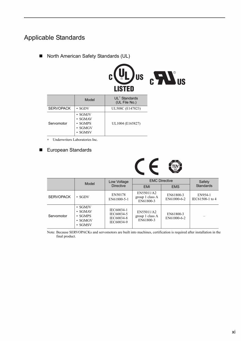
Applicable Standards
North American Safety Standards (UL)
∗ Underwriters Laboratories Inc.
European Standards
Note: Because SERVOPACKs and servomotors are built into machines, certification is required after installation in the final product.
Model UL∗ Standards(UL File No.)
SERVOPACK • SGDV UL508C (E147823)
Servomotor
• SGMJV• SGMAV• SGMPS• SGMGV• SGMSV
UL1004 (E165827)
Model Low Voltage Directive
EMC Directive Safety StandardsEMI EMS
SERVOPACK • SGDV EN50178EN61800-5-1
EN55011/A2group 1 class A
EN61800-3
EN61800-3EN61000-6-2
EN954-1IEC61508-1 to 4
Servomotor
• SGMJV• SGMAV• SGMPS• SGMGV• SGMSV
IEC60034-1IEC60034-5IEC60034-8IEC60034-9
EN55011/A2group 1 class A
EN61800-3
EN61800-3EN61000-6-2 –
xii
ContentsAbout this Manual . . . . . . . . . . . . . . . . . . . . . . . . . . . . . . . . . . . . . . . . . . . . . . . . . . . . . . . . iiiSafety Precautions. . . . . . . . . . . . . . . . . . . . . . . . . . . . . . . . . . . . . . . . . . . . . . . . . . . . . . . . viApplicable Standards . . . . . . . . . . . . . . . . . . . . . . . . . . . . . . . . . . . . . . . . . . . . . . . . . . . . . . xi
Chapter 1 Outline . . . . . . . . . . . . . . . . . . . . . . . . . . . . . . . . . . . . . . . . . . . .1-11.1 Σ-V Series SERVOPACKs . . . . . . . . . . . . . . . . . . . . . . . . . . . . . . . . . . . . . . . 1-21.2 Part Names . . . . . . . . . . . . . . . . . . . . . . . . . . . . . . . . . . . . . . . . . . . . . . . . . . 1-21.3 SERVOPACK Ratings and Specifications . . . . . . . . . . . . . . . . . . . . . . . . . . . 1-3
1.3.1 Ratings . . . . . . . . . . . . . . . . . . . . . . . . . . . . . . . . . . . . . . . . . . . . . . . . . . . . . . . . . . . . . . . . 1-31.3.2 Basic Specifications . . . . . . . . . . . . . . . . . . . . . . . . . . . . . . . . . . . . . . . . . . . . . . . . . . . . . . 1-41.3.3 MECHATROLINK-II Function Specifications . . . . . . . . . . . . . . . . . . . . . . . . . . . . . . . . . . . 1-6
1.4 SERVOPACK Internal Block Diagrams . . . . . . . . . . . . . . . . . . . . . . . . . . . . . 1-71.4.1 Single-phase 100 V, SGDV-R70F11A, -R90F11A, -2R1F11A Models . . . . . . . . . . . . . . . . 1-71.4.2 Single-phase 100 V, SGDV-2R8F11A Model . . . . . . . . . . . . . . . . . . . . . . . . . . . . . . . . . . . 1-71.4.3 Three-phase 200 V, SGDV-R70A11A, -R90A11A, -1R6A11A Models . . . . . . . . . . . . . . . . 1-81.4.4 Three-phase 200 V, SGDV-2R8A11A Model . . . . . . . . . . . . . . . . . . . . . . . . . . . . . . . . . . . 1-81.4.5 Three-phase 200 V, SGDV-3R8A11A, -5R5A11A, -7R6A11A Models . . . . . . . . . . . . . . . . 1-91.4.6 Three-phase 200 V, SGDV-120A11A Model . . . . . . . . . . . . . . . . . . . . . . . . . . . . . . . . . . . 1-91.4.7 Three-phase 200 V, SGDV-180A11A, -200A11A Models. . . . . . . . . . . . . . . . . . . . . . . . . 1-101.4.8 Three-phase 200 V, SGDV-330A11A Model . . . . . . . . . . . . . . . . . . . . . . . . . . . . . . . . . . 1-101.4.9 Three-phase 200 V, SGDV-470A11A, -550A11A Models. . . . . . . . . . . . . . . . . . . . . . . . . 1-111.4.10 Three-phase 200 V SGDV-590A11A, -780A11A Models . . . . . . . . . . . . . . . . . . . . . . . . 1-111.4.11 Three-phase 400 V, SGDV-1R9D11A, -3R5D11A, -5R4D11A Models. . . . . . . . . . . . . . 1-121.4.12 Three-phase 400 V, SGDV-8R4D11A, -120D11A Models . . . . . . . . . . . . . . . . . . . . . . . 1-121.4.13 Three-phase 400 V, SGDV-170D11A Model . . . . . . . . . . . . . . . . . . . . . . . . . . . . . . . . . 1-131.4.14 Three-phase 400 V, SGDV-210D11A, -260D11A Models . . . . . . . . . . . . . . . . . . . . . . . 1-131.4.15 Three-phase 400 V SGDV-280D11A, -370D11A Models . . . . . . . . . . . . . . . . . . . . . . . . 1-14
1.5 Examples of Servo System Configurations . . . . . . . . . . . . . . . . . . . . . . . . . 1-151.5.1 Connecting to SGDV- F11A SERVOPACK . . . . . . . . . . . . . . . . . . . . . . . . . . . . . . . 1-151.5.2 Connecting to SGDV- A11A SERVOPACK . . . . . . . . . . . . . . . . . . . . . . . . . . . . . . . 1-161.5.3 Connecting to SGDV- D11A SERVOPACK . . . . . . . . . . . . . . . . . . . . . . . . . . . . . . . 1-17
1.6 SERVOPACK Model Designation. . . . . . . . . . . . . . . . . . . . . . . . . . . . . . . . . 1-181.7 Inspection and Maintenance . . . . . . . . . . . . . . . . . . . . . . . . . . . . . . . . . . . . 1-19
Chapter 2 Panel Display and Operation of Digital Operator . . . . . . . . . . . .2-12.1 Panel Display . . . . . . . . . . . . . . . . . . . . . . . . . . . . . . . . . . . . . . . . . . . . . . . . . 2-2
2.1.1 Status Display . . . . . . . . . . . . . . . . . . . . . . . . . . . . . . . . . . . . . . . . . . . . . . . . . . . . . . . . . . 2-22.1.2 Alarm and Warning Display . . . . . . . . . . . . . . . . . . . . . . . . . . . . . . . . . . . . . . . . . . . . . . . . 2-22.1.3 Hard Wire Base Block Display . . . . . . . . . . . . . . . . . . . . . . . . . . . . . . . . . . . . . . . . . . . . . . 2-22.1.4 Overtravel Display . . . . . . . . . . . . . . . . . . . . . . . . . . . . . . . . . . . . . . . . . . . . . . . . . . . . . . . 2-2
2.2 Utility Function Mode (Fn ), Parameter Setting Mode (Pn ), Monitor Mode (Un ) . . . . . . . . . . . . . . . . . . . . . . . . . . . . . . . . . . . . . . . . . . . . . . 2-3
2.3 Utility Function Mode (Fn ). . . . . . . . . . . . . . . . . . . . . . . . . . . . . . . . . . . 2-32.4 How to Read a Parameter Explanation . . . . . . . . . . . . . . . . . . . . . . . . . . . . . 2-5
2.4.1 Explanation Method for Parameter Setting Type . . . . . . . . . . . . . . . . . . . . . . . . . . . . . . . 2-52.4.2 Explanation Method for Function Selection Type. . . . . . . . . . . . . . . . . . . . . . . . . . . . . . . . 2-52.4.3 Explanation Method for Tuning Parameters. . . . . . . . . . . . . . . . . . . . . . . . . . . . . . . . . . . . 2-6
2.5 Parameter Setting Mode (Pn ) . . . . . . . . . . . . . . . . . . . . . . . . . . . . . . . . 2-72.5.1 Parameter Setting Mode for Parameter Setting Type . . . . . . . . . . . . . . . . . . . . . . . . . . . . 2-72.5.2 Parameter Setting Mode for Function Selection Type . . . . . . . . . . . . . . . . . . . . . . . . . . . . 2-9
2.6 Monitor Mode (Un ) . . . . . . . . . . . . . . . . . . . . . . . . . . . . . . . . . . . . . . . 2-10
xiii
Chapter 3 Wiring and Connection . . . . . . . . . . . . . . . . . . . . . . . . . . . . . . . .3-13.1 Main Circuit Wiring. . . . . . . . . . . . . . . . . . . . . . . . . . . . . . . . . . . . . . . . . . . . . 3-2
3.1.1 Names and Functions of Main Circuit Terminals . . . . . . . . . . . . . . . . . . . . . . . . . . . . . . . . 3-33.1.2 SERVOPACK Main Circuit Wire Size. . . . . . . . . . . . . . . . . . . . . . . . . . . . . . . . . . . . . . . . . 3-43.1.3 Typical Main Circuit Wiring Examples . . . . . . . . . . . . . . . . . . . . . . . . . . . . . . . . . . . . . . . . 3-63.1.4 General Precautions for Wiring . . . . . . . . . . . . . . . . . . . . . . . . . . . . . . . . . . . . . . . . . . . . 3-103.1.5 Precautions When Using the SERVOPACK with a DC Power Input . . . . . . . . . . . . . . . . 3-113.1.6 Precautions when Using the SERVOPACK with Single-phase, 200 V Power Input . . . . 3-133.1.7 Precautions When Using More Than One SERVOPACK . . . . . . . . . . . . . . . . . . . . . . . . 3-16
3.2 I/O Signal Connections . . . . . . . . . . . . . . . . . . . . . . . . . . . . . . . . . . . . . . . . 3-173.2.1 I/O Signal (CN1) Names and Functions. . . . . . . . . . . . . . . . . . . . . . . . . . . . . . . . . . . . . . 3-173.2.2 I/O Signal Connector (CN1) Terminal Layout . . . . . . . . . . . . . . . . . . . . . . . . . . . . . . . . . . 3-183.2.3 Safety Function Signal (CN8) Names and Functions. . . . . . . . . . . . . . . . . . . . . . . . . . . . 3-183.2.4 Example of I/O Signal Connections . . . . . . . . . . . . . . . . . . . . . . . . . . . . . . . . . . . . . . . . . 3-19
3.3 I/O Signal Allocations. . . . . . . . . . . . . . . . . . . . . . . . . . . . . . . . . . . . . . . . . . 3-203.3.1 Input Signal Allocations . . . . . . . . . . . . . . . . . . . . . . . . . . . . . . . . . . . . . . . . . . . . . . . . . . 3-203.3.2 Output Signal Allocation. . . . . . . . . . . . . . . . . . . . . . . . . . . . . . . . . . . . . . . . . . . . . . . . . . 3-22
3.4 Examples of Connection to Host Controller . . . . . . . . . . . . . . . . . . . . . . . . . 3-233.4.1 Sequence Input Circuits . . . . . . . . . . . . . . . . . . . . . . . . . . . . . . . . . . . . . . . . . . . . . . . . . . 3-233.4.2 Sequence Output Circuits . . . . . . . . . . . . . . . . . . . . . . . . . . . . . . . . . . . . . . . . . . . . . . . .3-25
3.5 Wiring MECHATROLINK-II Communications . . . . . . . . . . . . . . . . . . . . . . . 3-273.6 Examples of Encoder Connection . . . . . . . . . . . . . . . . . . . . . . . . . . . . . . . . 3-28
3.6.1 Connection Example of an Encoder. . . . . . . . . . . . . . . . . . . . . . . . . . . . . . . . . . . . . . . . . 3-283.6.2 CN2 Encoder Connector Terminal Layout . . . . . . . . . . . . . . . . . . . . . . . . . . . . . . . . . . . . 3-29
3.7 Connecting Regenerative Resistors . . . . . . . . . . . . . . . . . . . . . . . . . . . . . . 3-303.7.1 Connecting Regenerative Resistors. . . . . . . . . . . . . . . . . . . . . . . . . . . . . . . . . . . . . . . . . 3-303.7.2 Setting Regenerative Resistor Capacity. . . . . . . . . . . . . . . . . . . . . . . . . . . . . . . . . . . . . . 3-31
3.8 Noise Control and Measures for Harmonic Suppression. . . . . . . . . . . . . . . 3-323.8.1 Wiring for Noise Control . . . . . . . . . . . . . . . . . . . . . . . . . . . . . . . . . . . . . . . . . . . . . . . . . . 3-323.8.2 Precautions on Connecting Noise Filter . . . . . . . . . . . . . . . . . . . . . . . . . . . . . . . . . . . . . . 3-343.8.3 Connecting AC/DC Reactor for Harmonic Suppression. . . . . . . . . . . . . . . . . . . . . . . . . . 3-36
Chapter 4 Operation . . . . . . . . . . . . . . . . . . . . . . . . . . . . . . . . . . . . . . . . . .4-14.1 MECHATROLINK-II Communications Settings . . . . . . . . . . . . . . . . . . . . . . . 4-3
4.1.1 Setting Switches SW1 and SW2 . . . . . . . . . . . . . . . . . . . . . . . . . . . . . . . . . . . . . . . . . . . . 4-34.2 MECHATROLINK-II Commands . . . . . . . . . . . . . . . . . . . . . . . . . . . . . . . . . . 4-44.3 Setting Common Basic Functions . . . . . . . . . . . . . . . . . . . . . . . . . . . . . . . . . 4-5
4.3.1 Servomotor Rotation Direction . . . . . . . . . . . . . . . . . . . . . . . . . . . . . . . . . . . . . . . . . . . . . . 4-54.3.2 Overtravel. . . . . . . . . . . . . . . . . . . . . . . . . . . . . . . . . . . . . . . . . . . . . . . . . . . . . . . . . . . . . . 4-64.3.3 Software Limit Settings. . . . . . . . . . . . . . . . . . . . . . . . . . . . . . . . . . . . . . . . . . . . . . . . . . . . 4-94.3.4 Holding Brakes. . . . . . . . . . . . . . . . . . . . . . . . . . . . . . . . . . . . . . . . . . . . . . . . . . . . . . . . . 4-104.3.5 Stopping Servomotor after SV_OFF Command or Alarm Occurrence. . . . . . . . . . . . . . . 4-144.3.6 Instantaneous Power Interruption Settings . . . . . . . . . . . . . . . . . . . . . . . . . . . . . . . . . . . 4-164.3.7 SEMI-F47 Function (Torque Limit Function for Low Power Supply Voltage
for Main Circuit) . . . . . . . . . . . . . . . . . . . . . . . . . . . . . . . . . . . . . . . . . . . . . . . . . . . . . . . . 4-174.3.8 Setting Motor Overload Detection Level . . . . . . . . . . . . . . . . . . . . . . . . . . . . . . . . . . . . . 4-20
4.4 Trial Operation . . . . . . . . . . . . . . . . . . . . . . . . . . . . . . . . . . . . . . . . . . . . . . . 4-224.4.1 Inspection and Checking before Trial Operation . . . . . . . . . . . . . . . . . . . . . . . . . . . . . . . 4-224.4.2 Trial Operation via MECHATROLINK-II . . . . . . . . . . . . . . . . . . . . . . . . . . . . . . . . . . . . . . 4-234.4.3 Electronic Gear . . . . . . . . . . . . . . . . . . . . . . . . . . . . . . . . . . . . . . . . . . . . . . . . . . . . . . . . 4-244.4.4 Encoder Output Pulses . . . . . . . . . . . . . . . . . . . . . . . . . . . . . . . . . . . . . . . . . . . . . . . . . . 4-274.4.5 Encoder Output Pulse Setting . . . . . . . . . . . . . . . . . . . . . . . . . . . . . . . . . . . . . . . . . . . . . 4-28
4.5 Test Without Motor Function . . . . . . . . . . . . . . . . . . . . . . . . . . . . . . . . . . . . 4-294.5.1 Related Parameters . . . . . . . . . . . . . . . . . . . . . . . . . . . . . . . . . . . . . . . . . . . . . . . . . . . . . 4-294.5.2 Limitations . . . . . . . . . . . . . . . . . . . . . . . . . . . . . . . . . . . . . . . . . . . . . . . . . . . . . . . . . . . . 4-294.5.3 Digital Operator Display during Testing without Motor . . . . . . . . . . . . . . . . . . . . . . . . . . . 4-31
xiv
4.6 Limiting Torque . . . . . . . . . . . . . . . . . . . . . . . . . . . . . . . . . . . . . . . . . . . . . . . 4-324.6.1 Internal Torque Limit. . . . . . . . . . . . . . . . . . . . . . . . . . . . . . . . . . . . . . . . . . . . . . . . . . . . . 4-324.6.2 External Torque Limit . . . . . . . . . . . . . . . . . . . . . . . . . . . . . . . . . . . . . . . . . . . . . . . . . . . . 4-334.6.3 Checking Output Torque Limiting during Operation . . . . . . . . . . . . . . . . . . . . . . . . . . . . . 4-34
4.7 Absolute Encoders . . . . . . . . . . . . . . . . . . . . . . . . . . . . . . . . . . . . . . . . . . . . 4-354.7.1 Encoder Resolutions . . . . . . . . . . . . . . . . . . . . . . . . . . . . . . . . . . . . . . . . . . . . . . . . . . . . 4-354.7.2 Absolute Encoder Data Backup . . . . . . . . . . . . . . . . . . . . . . . . . . . . . . . . . . . . . . . . . . . . 4-364.7.3 Battery Replacement . . . . . . . . . . . . . . . . . . . . . . . . . . . . . . . . . . . . . . . . . . . . . . . . . . . . 4-374.7.4 Absolute Encoder Setup . . . . . . . . . . . . . . . . . . . . . . . . . . . . . . . . . . . . . . . . . . . . . . . . . 4-394.7.5 Absolute Encoder Reception Sequence . . . . . . . . . . . . . . . . . . . . . . . . . . . . . . . . . . . . . 4-404.7.6 Multiturn Limit Setting. . . . . . . . . . . . . . . . . . . . . . . . . . . . . . . . . . . . . . . . . . . . . . . . . . . . 4-434.7.7 Multiturn Limit Disagreement Alarm (A.CC0) . . . . . . . . . . . . . . . . . . . . . . . . . . . . . . . . . . 4-444.7.8 Absolute Encoder Origin Offset . . . . . . . . . . . . . . . . . . . . . . . . . . . . . . . . . . . . . . . . . . . . 4-45
4.8 Safety Function . . . . . . . . . . . . . . . . . . . . . . . . . . . . . . . . . . . . . . . . . . . . . . 4-464.8.1 Hard Wire Base Block (HWBB) Function . . . . . . . . . . . . . . . . . . . . . . . . . . . . . . . . . . . . . 4-464.8.2 External Device Monitor (EDM1) . . . . . . . . . . . . . . . . . . . . . . . . . . . . . . . . . . . . . . . . . . . 4-514.8.3 Application Example of Safety Functions. . . . . . . . . . . . . . . . . . . . . . . . . . . . . . . . . . . . . 4-534.8.4 Confirming Safety Functions . . . . . . . . . . . . . . . . . . . . . . . . . . . . . . . . . . . . . . . . . . . . . . 4-544.8.5 Connecting a Safety Device. . . . . . . . . . . . . . . . . . . . . . . . . . . . . . . . . . . . . . . . . . . . . . . 4-554.8.6 Precautions for Safety Functions . . . . . . . . . . . . . . . . . . . . . . . . . . . . . . . . . . . . . . . . . . . 4-56
Chapter 5 Adjustments . . . . . . . . . . . . . . . . . . . . . . . . . . . . . . . . . . . . . . . .5-15.1 Adjustments and Basic Adjustment Procedure . . . . . . . . . . . . . . . . . . . . . . . 5-3
5.1.1 Adjustments . . . . . . . . . . . . . . . . . . . . . . . . . . . . . . . . . . . . . . . . . . . . . . . . . . . . . . . . . . . . 5-35.1.2 Basic Adjustment Procedure . . . . . . . . . . . . . . . . . . . . . . . . . . . . . . . . . . . . . . . . . . . . . . . 5-45.1.3 Monitoring Analog Signals . . . . . . . . . . . . . . . . . . . . . . . . . . . . . . . . . . . . . . . . . . . . . . . . . 5-55.1.4 Safety Precautions on Adjustment of Servo Gains . . . . . . . . . . . . . . . . . . . . . . . . . . . . . . 5-7
5.2 Tuning-less Function . . . . . . . . . . . . . . . . . . . . . . . . . . . . . . . . . . . . . . . . . . 5-105.2.1 Tuning-less Function . . . . . . . . . . . . . . . . . . . . . . . . . . . . . . . . . . . . . . . . . . . . . . . . . . . . 5-105.2.2 Tuning-less Levels Setting (Fn200) Procedure . . . . . . . . . . . . . . . . . . . . . . . . . . . . . . . . 5-13
5.3 Advanced Autotuning (Fn201) . . . . . . . . . . . . . . . . . . . . . . . . . . . . . . . . . . . 5-165.3.1 Advanced Autotuning . . . . . . . . . . . . . . . . . . . . . . . . . . . . . . . . . . . . . . . . . . . . . . . . . . . . 5-165.3.2 Advanced Autotuning Procedure . . . . . . . . . . . . . . . . . . . . . . . . . . . . . . . . . . . . . . . . . . . 5-195.3.3 Related Parameters . . . . . . . . . . . . . . . . . . . . . . . . . . . . . . . . . . . . . . . . . . . . . . . . . . . . . 5-25
5.4 Advanced Autotuning by Reference (Fn202) . . . . . . . . . . . . . . . . . . . . . . . . 5-265.4.1 Advanced Autotuning by Reference. . . . . . . . . . . . . . . . . . . . . . . . . . . . . . . . . . . . . . . . . 5-265.4.2 Advanced Autotuning by Reference Procedure . . . . . . . . . . . . . . . . . . . . . . . . . . . . . . . . 5-295.4.3 Related Parameters . . . . . . . . . . . . . . . . . . . . . . . . . . . . . . . . . . . . . . . . . . . . . . . . . . . . . 5-33
5.5 One-parameter Tuning (Fn203) . . . . . . . . . . . . . . . . . . . . . . . . . . . . . . . . . . 5-345.5.1 One-parameter Tuning . . . . . . . . . . . . . . . . . . . . . . . . . . . . . . . . . . . . . . . . . . . . . . . . . . . 5-345.5.2 One-parameter Tuning Procedure . . . . . . . . . . . . . . . . . . . . . . . . . . . . . . . . . . . . . . . . . . 5-365.5.3 One-parameter Tuning Example . . . . . . . . . . . . . . . . . . . . . . . . . . . . . . . . . . . . . . . . . . . 5-425.5.4 Related Parameters . . . . . . . . . . . . . . . . . . . . . . . . . . . . . . . . . . . . . . . . . . . . . . . . . . . . . 5-43
5.6 Anti-Resonance Control Adjustment Function (Fn204) . . . . . . . . . . . . . . . . 5-445.6.1 Anti-Resonance Control Adjustment Function . . . . . . . . . . . . . . . . . . . . . . . . . . . . . . . . . 5-445.6.2 Anti-Resonance Control Adjustment Function Operating Procedure. . . . . . . . . . . . . . . . 5-455.6.3 Related Parameters . . . . . . . . . . . . . . . . . . . . . . . . . . . . . . . . . . . . . . . . . . . . . . . . . . . . . 5-49
5.7 Vibration Suppression Function (Fn205) . . . . . . . . . . . . . . . . . . . . . . . . . . . 5-505.7.1 Vibration Suppression Function . . . . . . . . . . . . . . . . . . . . . . . . . . . . . . . . . . . . . . . . . . . . 5-505.7.2 Vibration Suppression Function Operating Procedure. . . . . . . . . . . . . . . . . . . . . . . . . . . 5-515.7.3 Related Parameters . . . . . . . . . . . . . . . . . . . . . . . . . . . . . . . . . . . . . . . . . . . . . . . . . . . . . 5-54
5.8 Additional Adjustment Function . . . . . . . . . . . . . . . . . . . . . . . . . . . . . . . . . . 5-555.8.1 Switching Gain Settings . . . . . . . . . . . . . . . . . . . . . . . . . . . . . . . . . . . . . . . . . . . . . . . . . . 5-555.8.2 Friction Compensation . . . . . . . . . . . . . . . . . . . . . . . . . . . . . . . . . . . . . . . . . . . . . . . . . . . 5-605.8.3 Current Control Mode Selection. . . . . . . . . . . . . . . . . . . . . . . . . . . . . . . . . . . . . . . . . . . . 5-625.8.4 Current Gain Level Setting. . . . . . . . . . . . . . . . . . . . . . . . . . . . . . . . . . . . . . . . . . . . . . . . 5-625.8.5 Speed Detection Method Selection . . . . . . . . . . . . . . . . . . . . . . . . . . . . . . . . . . . . . . . . . 5-62
xv
5.9 Compatible Adjustment Function . . . . . . . . . . . . . . . . . . . . . . . . . . . . . . . . . 5-635.9.1 Feedforward Reference . . . . . . . . . . . . . . . . . . . . . . . . . . . . . . . . . . . . . . . . . . . . . . . . . . 5-635.9.2 Using the Mode Switch (P/PI Switching) . . . . . . . . . . . . . . . . . . . . . . . . . . . . . . . . . . . . . 5-635.9.3 Torque Reference Filter . . . . . . . . . . . . . . . . . . . . . . . . . . . . . . . . . . . . . . . . . . . . . . . . . . 5-685.9.4 Position Integral Time Constant . . . . . . . . . . . . . . . . . . . . . . . . . . . . . . . . . . . . . . . . . . . . 5-70
Chapter 6 Utility Functions (Fn ) . . . . . . . . . . . . . . . . . . . . . . . . . . . . .6-16.1 List of Utility Functions . . . . . . . . . . . . . . . . . . . . . . . . . . . . . . . . . . . . . . . . . . 6-26.2 Alarm History Display (Fn000) . . . . . . . . . . . . . . . . . . . . . . . . . . . . . . . . . . . . 6-36.3 JOG Operation (Fn002) . . . . . . . . . . . . . . . . . . . . . . . . . . . . . . . . . . . . . . . . . 6-46.4 Origin Search (Fn003) . . . . . . . . . . . . . . . . . . . . . . . . . . . . . . . . . . . . . . . . . . 6-66.5 Program JOG Operation (Fn004) . . . . . . . . . . . . . . . . . . . . . . . . . . . . . . . . . 6-86.6 Initializing Parameter Settings (Fn005) . . . . . . . . . . . . . . . . . . . . . . . . . . . . 6-136.7 Clearing Alarm History (Fn006) . . . . . . . . . . . . . . . . . . . . . . . . . . . . . . . . . . 6-146.8 Offset adjustment of Analog Monitor Output (Fn00C) . . . . . . . . . . . . . . . . . 6-156.9 Gain Adjustment of Analog Monitor Output (Fn00D) . . . . . . . . . . . . . . . . . . 6-176.10 Automatic Offset-Signal Adjustment of the Motor Current Detection
(Fn00E) . . . . . . . . . . . . . . . . . . . . . . . . . . . . . . . . . . . . . . . . . . . . . . . . . . . . 6-196.11 Manual Offset-Signal Adjustment of the Motor Current Detection
(Fn00F) . . . . . . . . . . . . . . . . . . . . . . . . . . . . . . . . . . . . . . . . . . . . . . . . . . . . 6-206.12 Write Prohibited Setting (Fn010) . . . . . . . . . . . . . . . . . . . . . . . . . . . . . . . . 6-216.13 Servomotor Model Display (Fn011) . . . . . . . . . . . . . . . . . . . . . . . . . . . . . . 6-236.14 Software Version Display (Fn012) . . . . . . . . . . . . . . . . . . . . . . . . . . . . . . . 6-246.15 Resetting Configuration Error of Option Module (Fn014) . . . . . . . . . . . . . 6-256.16 Vibration Detection Level Initialization (Fn01B) . . . . . . . . . . . . . . . . . . . . . 6-266.17 Display of SERVOPACK and Servomotor ID (Fn01E) . . . . . . . . . . . . . . . . 6-286.18 Display of Servomotor ID in Feedback Option Module (Fn01F) . . . . . . . . 6-296.19 Origin Setting (Fn020) . . . . . . . . . . . . . . . . . . . . . . . . . . . . . . . . . . . . . . . . 6-306.20 Software Reset (Fn030). . . . . . . . . . . . . . . . . . . . . . . . . . . . . . . . . . . . . . . 6-316.21 EasyFFT (Fn206). . . . . . . . . . . . . . . . . . . . . . . . . . . . . . . . . . . . . . . . . . . . 6-326.22 Online Vibration Monitor (Fn207). . . . . . . . . . . . . . . . . . . . . . . . . . . . . . . . 6-36
Chapter 7 Monitor Modes (Un ) . . . . . . . . . . . . . . . . . . . . . . . . . . . . .7-17.1 List of Monitor Modes. . . . . . . . . . . . . . . . . . . . . . . . . . . . . . . . . . . . . . . . . . . 7-27.2 Monitor Mode Display . . . . . . . . . . . . . . . . . . . . . . . . . . . . . . . . . . . . . . . . . . 7-3
Chapter 8 Fully-closed Loop Control. . . . . . . . . . . . . . . . . . . . . . . . . . . . . .8-18.1 System Configuration and Connection Example for SERVOPACK with Fully-
closed Loop Control. . . . . . . . . . . . . . . . . . . . . . . . . . . . . . . . . . . . . . . . . . . . 8-28.1.1 System Configuration. . . . . . . . . . . . . . . . . . . . . . . . . . . . . . . . . . . . . . . . . . . . . . . . . . . . . 8-28.1.2 Internal Configuration of Fully-closed Loop Control . . . . . . . . . . . . . . . . . . . . . . . . . . . . . . 8-38.1.3 Serial Converter Unit . . . . . . . . . . . . . . . . . . . . . . . . . . . . . . . . . . . . . . . . . . . . . . . . . . . . . 8-48.1.4 Connection Example of External Encoder by Heidenhain . . . . . . . . . . . . . . . . . . . . . . . . . 8-68.1.5 Connection Example of External Encoder by Mitutoyo . . . . . . . . . . . . . . . . . . . . . . . . . . . 8-78.1.6 Connection Example of External Encoder by Renishaw . . . . . . . . . . . . . . . . . . . . . . . . . . 8-88.1.7 Encoder Output Pulse Signals from SERVOPACK with a External Encoder
by Renishaw . . . . . . . . . . . . . . . . . . . . . . . . . . . . . . . . . . . . . . . . . . . . . . . . . . . . . . . . . . . 8-9
xvi
8.2 Settings for Fully-closed Loop Control . . . . . . . . . . . . . . . . . . . . . . . . . . . . . 8-108.2.1 Setting Order . . . . . . . . . . . . . . . . . . . . . . . . . . . . . . . . . . . . . . . . . . . . . . . . . . . . . . . . . . 8-108.2.2 Motor Rotation Direction . . . . . . . . . . . . . . . . . . . . . . . . . . . . . . . . . . . . . . . . . . . . . . . . . 8-118.2.3 Sine Wave Pitch (Frequency) for an External Encoder . . . . . . . . . . . . . . . . . . . . . . . . . . 8-128.2.4 Number of Encoder Output Pulses (PAO, PBO, and PCO) from the SERVOPACK . . . . 8-138.2.5 Absolute External Encoder Reception Sequence . . . . . . . . . . . . . . . . . . . . . . . . . . . . . . 8-148.2.6 Electronic Gear . . . . . . . . . . . . . . . . . . . . . . . . . . . . . . . . . . . . . . . . . . . . . . . . . . . . . . . . 8-178.2.7 Alarm Detection . . . . . . . . . . . . . . . . . . . . . . . . . . . . . . . . . . . . . . . . . . . . . . . . . . . . . . . . 8-178.2.8 Analog Monitor Signal . . . . . . . . . . . . . . . . . . . . . . . . . . . . . . . . . . . . . . . . . . . . . . . . . . . 8-188.2.9 Speed Feedback Method during Fully-closed Loop Control . . . . . . . . . . . . . . . . . . . . . . 8-18
Chapter 9 Troubleshooting . . . . . . . . . . . . . . . . . . . . . . . . . . . . . . . . . . . . .9-19.1 Troubleshooting . . . . . . . . . . . . . . . . . . . . . . . . . . . . . . . . . . . . . . . . . . . . . . . 9-2
9.1.1 List of Alarms . . . . . . . . . . . . . . . . . . . . . . . . . . . . . . . . . . . . . . . . . . . . . . . . . . . . . . . . . . . 9-29.1.2 Troubleshooting of Alarms . . . . . . . . . . . . . . . . . . . . . . . . . . . . . . . . . . . . . . . . . . . . . . . . . 9-6
9.2 Warning Displays . . . . . . . . . . . . . . . . . . . . . . . . . . . . . . . . . . . . . . . . . . . . . 9-219.2.1 List of Warnings . . . . . . . . . . . . . . . . . . . . . . . . . . . . . . . . . . . . . . . . . . . . . . . . . . . . . . . . 9-219.2.2 Troubleshooting of Warnings . . . . . . . . . . . . . . . . . . . . . . . . . . . . . . . . . . . . . . . . . . . . . . 9-22
9.3 Troubleshooting Malfunction Based on Operation and Conditions of the Servomotor . . . . . . . . . . . . . . . . . . . . . . . . . . . . . . . . . . . . . . . . . . . . . . . . . 9-25
Chapter 10 Appendix. . . . . . . . . . . . . . . . . . . . . . . . . . . . . . . . . . . . . . . . .10-110.1 List of Parameters . . . . . . . . . . . . . . . . . . . . . . . . . . . . . . . . . . . . . . . . . . . 10-2
10.1.1 Utility Functions . . . . . . . . . . . . . . . . . . . . . . . . . . . . . . . . . . . . . . . . . . . . . . . . . . . . . . . 10-210.1.2 Parameters. . . . . . . . . . . . . . . . . . . . . . . . . . . . . . . . . . . . . . . . . . . . . . . . . . . . . . . . . . . 10-3
10.2 Monitor Modes . . . . . . . . . . . . . . . . . . . . . . . . . . . . . . . . . . . . . . . . . . . . . 10-3210.3 Parameter Recording Table . . . . . . . . . . . . . . . . . . . . . . . . . . . . . . . . . . . 10-33
Index. . . . . . . . . . . . . . . . . . . . . . . . . . . . . . . . . . . . . . . . . . . . . . . . . . . Index-1
Revision History
1-1
1
Ou
tlin
e
1Outline
1.1 Σ-V Series SERVOPACKs . . . . . . . . . . . . . . . . . . . . . . . . . . . . . . . . . . . . .1-2
1.2 Part Names . . . . . . . . . . . . . . . . . . . . . . . . . . . . . . . . . . . . . . . . . . . . . . . .1-2
1.3 SERVOPACK Ratings and Specifications . . . . . . . . . . . . . . . . . . . . . . . . .1-31.3.1 Ratings . . . . . . . . . . . . . . . . . . . . . . . . . . . . . . . . . . . . . . . . . . . . . . . . . . . . . . . . . . . . 1-31.3.2 Basic Specifications . . . . . . . . . . . . . . . . . . . . . . . . . . . . . . . . . . . . . . . . . . . . . . . . . . 1-41.3.3 MECHATROLINK-II Function Specifications . . . . . . . . . . . . . . . . . . . . . . . . . . . . . . . . 1-6
1.4 SERVOPACK Internal Block Diagrams . . . . . . . . . . . . . . . . . . . . . . . . . . .1-71.4.1 Single-phase 100 V, SGDV-R70F11A, -R90F11A, -2R1F11A Models . . . . . . . . . . . . 1-71.4.2 Single-phase 100 V, SGDV-2R8F11A Model . . . . . . . . . . . . . . . . . . . . . . . . . . . . . . . 1-71.4.3 Three-phase 200 V, SGDV-R70A11A, -R90A11A, -1R6A11A Models . . . . . . . . . . . . 1-81.4.4 Three-phase 200 V, SGDV-2R8A11A Model . . . . . . . . . . . . . . . . . . . . . . . . . . . . . . . . 1-81.4.5 Three-phase 200 V, SGDV-3R8A11A, -5R5A11A, -7R6A11A Models . . . . . . . . . . . . 1-91.4.6 Three-phase 200 V, SGDV-120A11A Model . . . . . . . . . . . . . . . . . . . . . . . . . . . . . . . . 1-91.4.7 Three-phase 200 V, SGDV-180A11A, -200A11A Models . . . . . . . . . . . . . . . . . . . . . 1-101.4.8 Three-phase 200 V, SGDV-330A11A Model . . . . . . . . . . . . . . . . . . . . . . . . . . . . . . . 1-101.4.9 Three-phase 200 V, SGDV-470A11A, -550A11A Models . . . . . . . . . . . . . . . . . . . . . 1-111.4.10 Three-phase 200 V SGDV-590A11A, -780A11A Models . . . . . . . . . . . . . . . . . . . . 1-111.4.11 Three-phase 400 V, SGDV-1R9D11A, -3R5D11A, -5R4D11A Models . . . . . . . . . . 1-121.4.12 Three-phase 400 V, SGDV-8R4D11A, -120D11A Models . . . . . . . . . . . . . . . . . . . . 1-121.4.13 Three-phase 400 V, SGDV-170D11A Model . . . . . . . . . . . . . . . . . . . . . . . . . . . . . . 1-131.4.14 Three-phase 400 V, SGDV-210D11A, -260D11A Models . . . . . . . . . . . . . . . . . . . . 1-131.4.15 Three-phase 400 V SGDV-280D11A, -370D11A Models . . . . . . . . . . . . . . . . . . . . 1-14
1.5 Examples of Servo System Configurations . . . . . . . . . . . . . . . . . . . . . . .1-151.5.1 Connecting to SGDV- F11A SERVOPACK . . . . . . . . . . . . . . . . . . . . . . . . . . . . 1-151.5.2 Connecting to SGDV- A11A SERVOPACK . . . . . . . . . . . . . . . . . . . . . . . . . . . . 1-161.5.3 Connecting to SGDV- D11A SERVOPACK . . . . . . . . . . . . . . . . . . . . . . . . . . . 1-17
1.6 SERVOPACK Model Designation . . . . . . . . . . . . . . . . . . . . . . . . . . . . . . 1-18
1.7 Inspection and Maintenance . . . . . . . . . . . . . . . . . . . . . . . . . . . . . . . . . . 1-19
1 Outline
1-2
1.1 Σ-V Series SERVOPACKsThe Σ-V Series SERVOPACKs are designed for applications that require frequent high-speed, high-pre-cision positioning. The SERVOPACK makes the most of machine performance in the shortest time possi-ble, thus contributing to improving productivity.
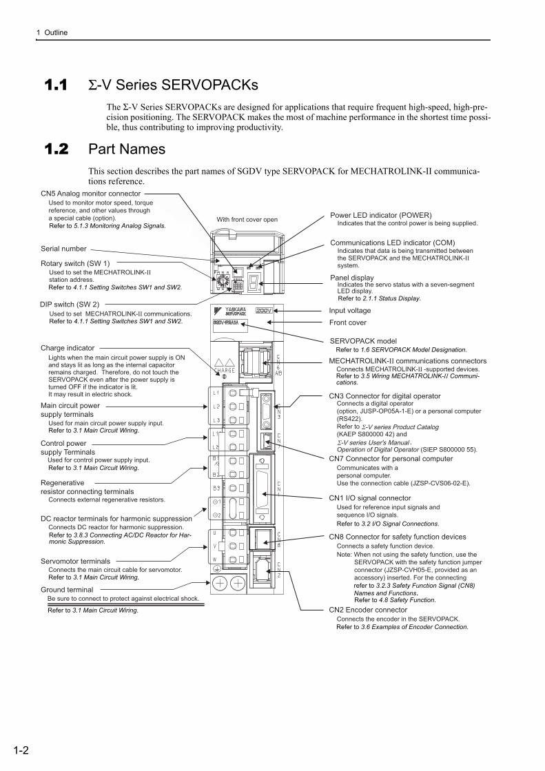
1.2 Part NamesThis section describes the part names of SGDV type SERVOPACK for MECHATROLINK-II communica-tions reference.
CN5 Analog monitor connectorUsed to monitor motor speed, torquereference, and other values througha special cable (option).Refer to 6.1.3 Analog Monitor.
Panel display
Connects external regenerative resistors.
Used for control power supply input.Refer to 3.1 Main Circuit Wiring.
Charge indicator
Front cover
CN3 Connector for digital operatorConnects a digital operator(option, JUSP-OP05A-1-E) or a personal computer(RS422).Refer to(KAEP S800000 42) and ,Operation of Digital Operator (SIEP S800000 55).
CN1 I/O signal connectorUsed for reference input signals andsequence I/O signals.Refer to 3.2 I/O Signal Connections.
CN7 Connector for personal computerCommunicates with apersonal computer.Use the connection cable (JZSP-CVS06-02-E).
CN2 Encoder connectorConnects the encoder in the SERVOPACK.Refer to 3.6 Examples of Encoder Connection.
Ground terminalBe sure to connect to protect against electrical shock.
Refer to 3.1 Main Circuit Wiring.
Main circuit power supply terminals
Used for main circuit power supply input.Refer to 3.1 Main Circuit Wiring.
Control power supply Terminals
Servomotor terminalsConnects the main circuit cable for servomotor.Refer to 3.1 Main Circuit Wiring.
SERVOPACK model Refer to 1.5 SERVOPACK Model Designation.
Regenerativeresistor connecting terminals
Input voltage
CN8 Connector for safety function devicesConnects a safety function device.
DC reactor terminals for harmonic suppressionConnects DC reactor for harmonic suppression.Refer to 3.8.3 Connecting DC Reactor for HormonicSuppression.
With front cover open
Used to set MECHATROLINK-II communications.Refer to 4.1.1
Lights when the main circuit power supply is ON and stays lit as long as the internal capacitor remains charged. Therefore, do not touch the SERVOPACK even after the power supply is turned OFF if the indicator is lit.It may result in electric shock.
Σ-V series Product Catalog
Σ-V series User's Manual
Note: When not using the safety function, use the SERVOPACK with the safety function jumper connector (JZSP-CVH05-E, provided as an accessory) inserted. For the connecting
method, refer to 3.2.3 Safety Function Signal
(CN8) Names and Function. For the operation, refer to 4.6 Safety Function.
Serial number
Rotary switch (SW 1)Used to set the MECHATROLINK-IIstation address. Refer to 4.1.1
DIP switch (SW 2)
Indicates the servo status with a seven-segmentLED display.Refer to 2.1.1 Status Display Mode
Power LED indicator (POWER)Indicates that the control power is being supplied.
Communications LED indicator (COM)Indicates that data is being transmitted betweenthe SERVOPACK and the MECHATROLINK-IIsystem.
MECHATROLINK-II communications connectorsConnects MECHATROLINK-II -supported devices.Refer to 3.5
Refer to 2.1.1 Status Display.
Refer to 3.1 Main Circuit Wiring.
Refer to 3.1 Main Circuit Wiring.
Refer to 3.1 Main Circuit Wiring.
Refer to 3.1 Main Circuit Wiring.
Refer to 3.2 I/O Signal Connections.
Refer to 1.6 SERVOPACK Model Designation.
Refer to 3.6 Examples of Encoder Connection.
refer to 3.2.3 Safety Function Signal (CN8) Names and Functions.Refer to 4.8 Safety Function.
Refer to 5.1.3 Monitoring Analog Signals.
Refer to 3.8.3 Connecting AC/DC Reactor for Har-monic Suppression.
Refer to 3.5 Wiring MECHATROLINK-II Communi-cations.
Refer to 4.1.1 Setting Switches SW1 and SW2.
Refer to 4.1.1 Setting Switches SW1 and SW2.
1.3 SERVOPACK Ratings and Specifications
1-3
1
Ou
tlin
e
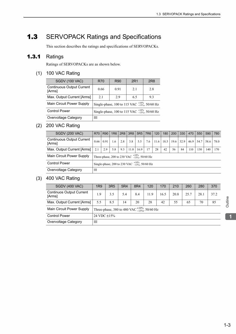
1.3 SERVOPACK Ratings and SpecificationsThis section describes the ratings and specifications of SERVOPACKs.
1.3.1 RatingsRatings of SERVOPACKs are as shown below.
(1) 100 VAC Rating
(2) 200 VAC Rating
(3) 400 VAC Rating
SGDV (100 VAC) R70 R90 2R1 2R8
Continuous Output Current [Arms] 0.66 0.91 2.1 2.8
Max. Output Current [Arms] 2.1 2.9 6.5 9.3
Main Circuit Power Supply Single-phase, 100 to 115 VAC , 50/60 Hz
Control Power Single-phase, 100 to 115 VAC , 50/60 Hz
Overvoltage Category III
SGDV (200 VAC) R70 R90 1R6 2R8 3R8 5R5 7R6 120 180 200 330 470 550 590 780
Continuous Output Current [Arms] 0.66 0.91 1.6 2.8 3.8 5.5 7.6 11.6 18.5 19.6 32.9 46.9 54.7 58.6 78.0
Max. Output Current [Arms] 2.1 2.9 5.8 9.3 11.0 16.9 17 28 42 56 84 110 130 140 170
Main Circuit Power Supply Three-phase, 200 to 230 VAC , 50/60 Hz
Control Power Single-phase, 200 to 230 VAC , 50/60 Hz
Overvoltage Category III
SGDV (400 VAC) 1R9 3R5 5R4 8R4 120 170 210 260 280 370
Continuos Output Current [Arms] 1.9 3.5 5.4 8.4 11.9 16.5 20.8 25.7 28.1 37.2
Max. Output Current [Arms] 5.5 8.5 14 20 28 42 55 65 70 85
Main Circuit Power Supply Three-phase, 380 to 480 VAC , 50/60 Hz
Control Power 24 VDC ±15%
Overvoltage Category III
+10%−15%
+10%−15%
+10%−15%
+10%−15%
+10%−15%
1 Outline
1.3.2 Basic Specifications
1-4
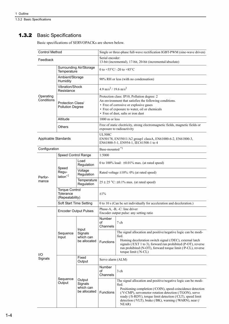
1.3.2 Basic SpecificationsBasic specifications of SERVOPACKs are shown below.
Control Method Single or three-phase full-wave rectification IGBT-PWM (sine-wave driven)
Feedback Serial encoder: 13-bit (incremental), 17-bit, 20-bit (incremental/absolute)
OperatingConditions
Surrounding Air/StorageTemperature 0 to +55°C/ -20 to +85°C
Ambient/StorageHumidity 90% RH or less (with no condensation)
Vibration/ShockResistance 4.9 m/s2 / 19.6 m/s2
Protection Class/Pollution Degree
Protection class: IP10, Pollution degree: 2An environment that satisfies the following conditions.• Free of corrosive or explosive gases• Free of exposure to water, oil or chemicals• Free of dust, salts or iron dust
Altitude 1000 m or less
Others Free of static electricity, strong electromagnetic fields, magnetic fields or exposure to radioactivity
Applicable StandardsUL508CEN50178, EN55011/A2 group1 classA, EN61000-6-2, EN61800-3, EN61800-5-1, EN954-1, IEC61508-1 to 4
Configuration Base-mounted *1
Perfor-mance
Speed Control Range 1:5000
SpeedRegu-lation∗2
LoadRegulation 0 to 100% load: ±0.01% max. (at rated speed)
VoltageRegulation Rated voltage ±10%: 0% (at rated speed)
Temperature Regulation 25 ± 25 °C: ±0.1% max. (at rated speed)
Torque ControlTolerance (Repeatability)
±1%
Soft Start Time Setting 0 to 10 s (Can be set individually for acceleration and deceleration.)
I/OSignals
Encoder Output Pulses Phase-A, -B, -C: line driver Encoder output pulse: any setting ratio
SequenceInput
Input Signals which canbe allocated
Number of Channels
7 ch
Functions
The signal allocation and positive/negative logic can be modi-fied.
Homing deceleration switch signal (/DEC), external latch signals (/EXT 1 to 3), forward run prohibited (P-OT), reverse run prohibited (N-OT), forward torque limit (/P-CL), reverse torque limit (/N-CL)
Sequence Output
Fixed Output Servo alarm (ALM)
Output Signals which can be allocated
Number of Channels
3 ch
Functions
The signal allocation and positive/negative logic can be modi-fied.
Positioning completion (/COIN), speed coincidence detection (/V-CMP), servomotor rotation detection (/TGON), servo ready (/S-RDY), torque limit detection (/CLT), speed limit detection (/VLT), brake (/BK), warning (/WARN), near (/NEAR)
1.3 SERVOPACK Ratings and Specifications
1-5
1
Ou
tlin
e
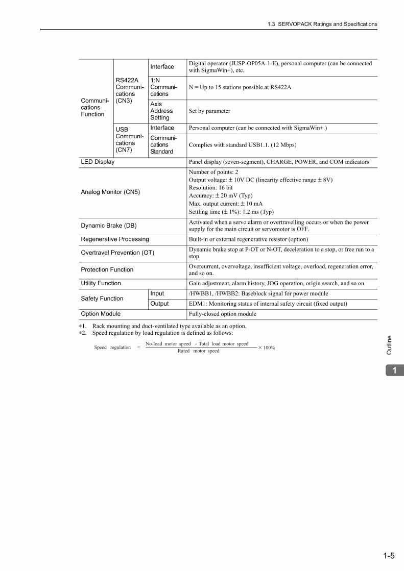
∗1. Rack mounting and duct-ventilated type available as an option.∗2. Speed regulation by load regulation is defined as follows:
Communi-cations Function
RS422ACommuni-cations(CN3)
Interface Digital operator (JUSP-OP05A-1-E), personal computer (can be connected with SigmaWin+), etc.
1:N Communi-cations
N = Up to 15 stations possible at RS422A
Axis Address Setting
Set by parameter
USBCommuni-cations(CN7)
Interface Personal computer (can be connected with SigmaWin+.)
Communi-cations Standard
Complies with standard USB1.1. (12 Mbps)
LED Display Panel display (seven-segment), CHARGE, POWER, and COM indicators
Analog Monitor (CN5)
Number of points: 2Output voltage: ± 10V DC (linearity effective range ± 8V)Resolution: 16 bitAccuracy: ± 20 mV (Typ)Max. output current: ± 10 mASettling time (± 1%): 1.2 ms (Typ)
Dynamic Brake (DB) Activated when a servo alarm or overtravelling occurs or when the power supply for the main circuit or servomotor is OFF.
Regenerative Processing Built-in or external regenerative resistor (option)
Overtravel Prevention (OT) Dynamic brake stop at P-OT or N-OT, deceleration to a stop, or free run to a stop
Protection Function Overcurrent, overvoltage, insufficient voltage, overload, regeneration error, and so on.
Utility Function Gain adjustment, alarm history, JOG operation, origin search, and so on.
Safety Function Input /HWBB1, /HWBB2: Baseblock signal for power module
Output EDM1: Monitoring status of internal safety circuit (fixed output)
Option Module Fully-closed option module
Speed regulation =No-load motor speed Total load motor speed
Rated motor speed× 100%
-
1 Outline
1.3.3 MECHATROLINK-II Function Specifications
1-6
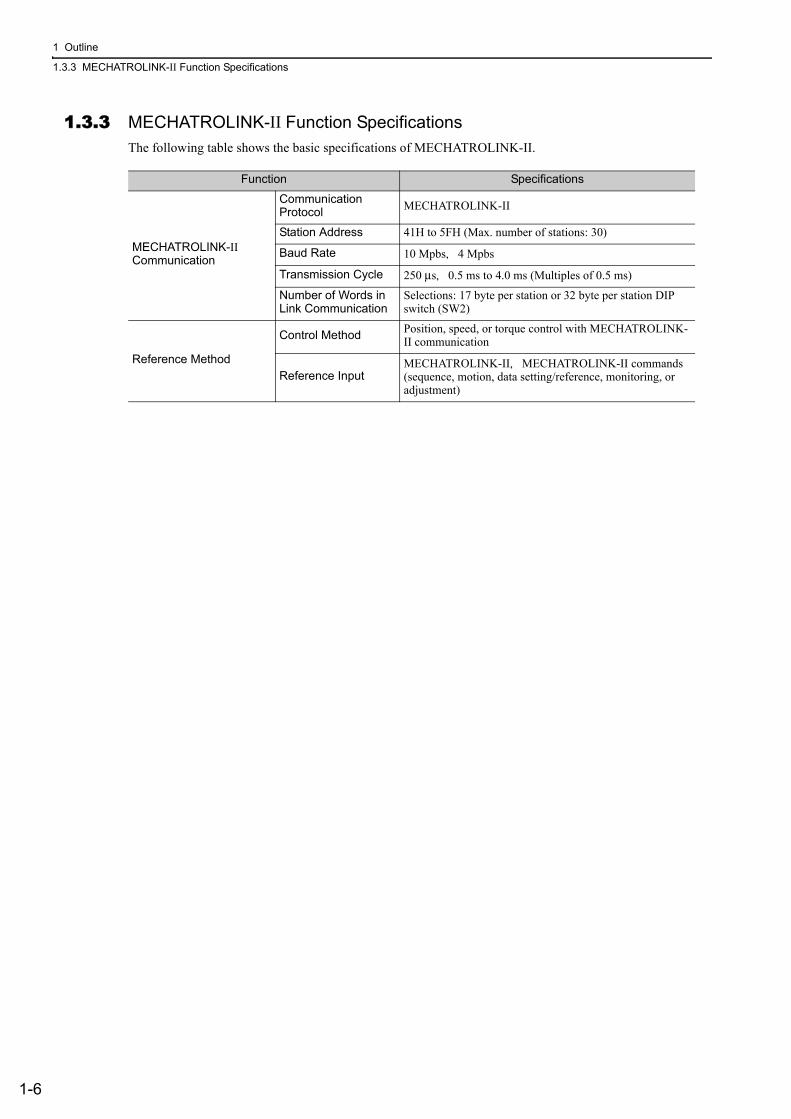
1.3.3 MECHATROLINK-II Function SpecificationsThe following table shows the basic specifications of MECHATROLINK-II.
Function Specifications
MECHATROLINK-II Communication
Communication Protocol MECHATROLINK-II
Station Address 41H to 5FH (Max. number of stations: 30)
Baud Rate 10 Mpbs,4 Mpbs
Transmission Cycle 250 μs,0.5 ms to 4.0 ms (Multiples of 0.5 ms)
Number of Words in Link Communication
Selections: 17 byte per station or 32 byte per station DIP switch (SW2)
Reference Method
Control Method Position, speed, or torque control with MECHATROLINK-II communication
Reference InputMECHATROLINK-II,MECHATROLINK-II commands (sequence, motion, data setting/reference, monitoring, or adjustment)
1.4 SERVOPACK Internal Block Diagrams
1-7
1
Ou
tlin
e
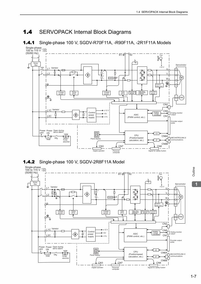
1.4 SERVOPACK Internal Block Diagrams
1.4.1 Single-phase 100 V, SGDV-R70F11A, -R90F11A, -2R1F11A Models
1.4.2 Single-phase 100 V, SGDV-2R8F11A Model
1KM
CHARGE M
ENC
10%15%
1KM L1
B1/ B2
L2
L1C
L2C
U
V
W
12 V
+5V
+17V
1KM
1Ry
Servomotor+12 V
Fan
CN3 CN7 CN8
CN2
I/O
I/F
CN1
CN6A
CN6B
CN5
MECHATROLINK-II communications
Single-phase100 to 115 V(50/60 Hz)
Noisefilter
Varistor
Voltagesensor
Relaydrive
Varistor
Surgeabsorber
PowerOFF
PowerON
Open duringservo alarm
Controlpowersupply
CPU(Position/speedcalculation, etc.)
Panel display
Digital operator Personalcomputer
Signal for safety fuction
Encoder outputpulse
Analog monitoroutputASIC
(PWM control, etc.)
Analogvoltageconverter
Currentsensor
Dynamicbrake circuit
Gatedrive
Voltagesensor
Gate driveovercurrentprotector
Temperaturesensor
10%15%
L1
B1/ B2
L2
L1C
L2C
U
V
W
1KM
1KM
1Ry
CHARGE M
+12 V
ENC
12 V
+5V
+17V
CN3 CN7 CN8
CN2
I/O
I/F
CN1
CN6A
CN6B
CN5
Servomotor
Fan
MECHATROLINK-II communications
Single-phase100 to 115 V(50/60 Hz)
Noisefilter
Varistor
Voltagesensor
Relaydrive
Varistor
Surgeabsorber
PowerOFF
PowerON
Open duringservo alarm
Controlpowersupply
CPU(Position/speedcalculation, etc.)
Panel display
Digital operator Personalcomputer
Signal for safety fuction
Encoder outputpulse
Analog monitoroutputASIC
(PWM control, etc.)
Analogvoltageconverter
Currentsensor
Dynamicbrake circuit
Gatedrive
Voltagesensor
Gate driveovercurrentprotector
Temperaturesensor
1 Outline
1.4.3 Three-phase 200 V, SGDV-R70A11A, -R90A11A, -1R6A11A Models
1-8
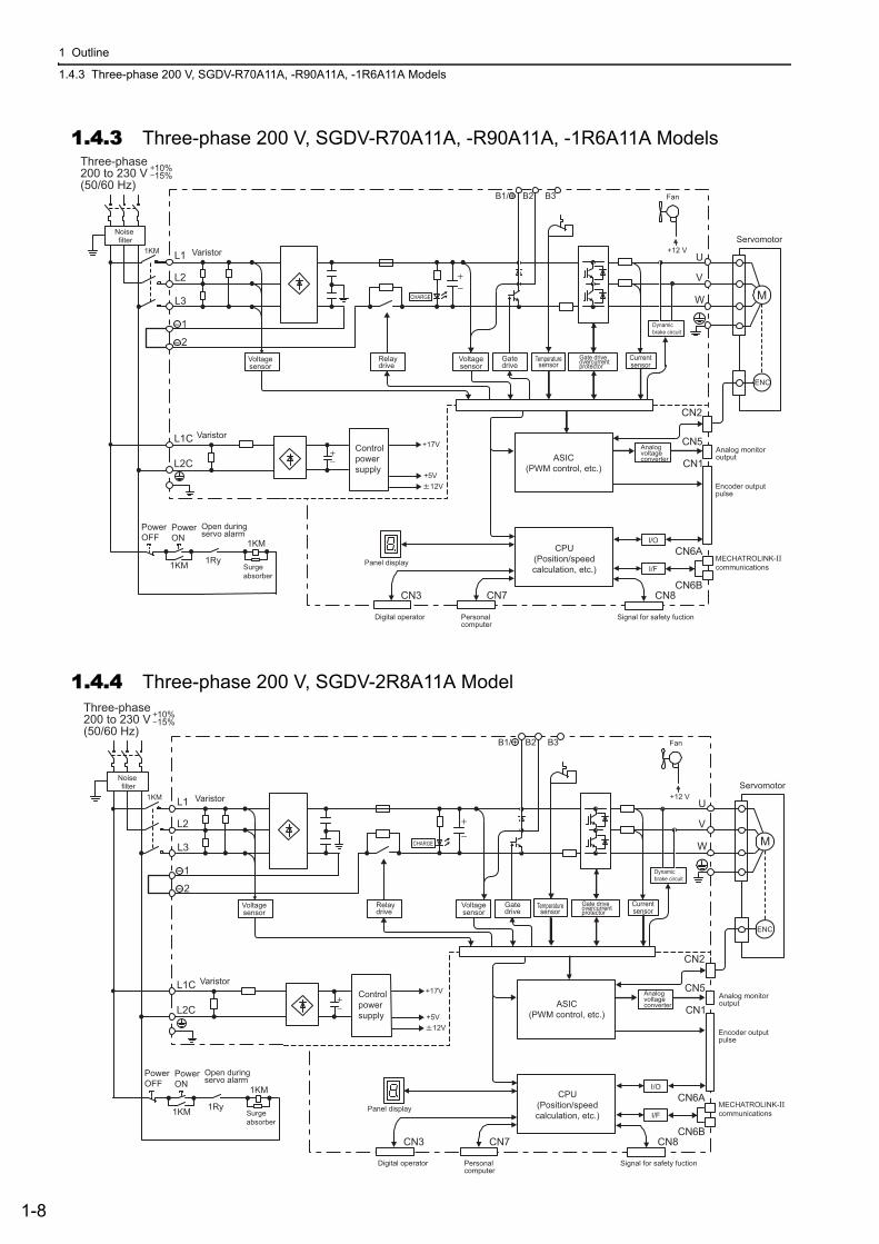
1.4.3 Three-phase 200 V, SGDV-R70A11A, -R90A11A, -1R6A11A Models
1.4.4 Three-phase 200 V, SGDV-2R8A11A Model
10%15%
1KM L1
B1/ B2 B3
L2
L3
1
2
L1C
L2C
U
V
W
+17V
12V+5V
1KM
1KM
1Ry
ENC
MCHARGE
CN3 CN7 CN8
CN2
I/O
I/F
CN1
CN6A
CN6B
CN5
+12 VServomotor
Fan
MECHATROLINK-II communications
Three-phase200 to 230 V(50/60 Hz)
Noisefilter
Varistor
Voltagesensor
Relaydrive
Varistor
Surgeabsorber
PowerOFF
PowerON
Open duringservo alarm
Controlpowersupply
CPU(Position/speedcalculation, etc.)
Panel display
Digital operator Personalcomputer
Signal for safety fuction
Encoder outputpulse
Analog monitoroutputASIC
(PWM control, etc.)
Analogvoltageconverter
Currentsensor
Dynamicbrake circuit
Gatedrive
Voltagesensor
Gate driveovercurrentprotector
Temperaturesensor
1.4 SERVOPACK Internal Block Diagrams
1-9
1
Ou
tlin
e
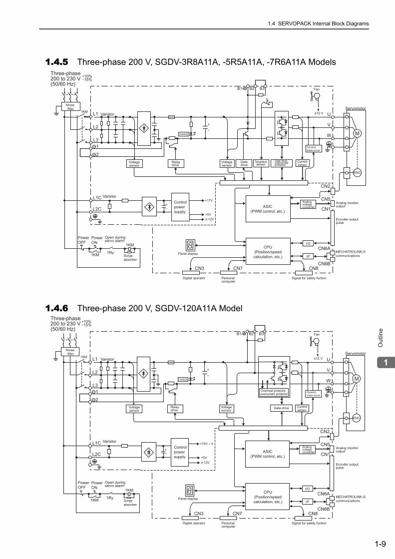
1.4.5 Three-phase 200 V, SGDV-3R8A11A, -5R5A11A, -7R6A11A Models
1.4.6 Three-phase 200 V, SGDV-120A11A Model
10%15%
1KM L1
B1/ B2 B3
L2
L31
2
L1C
L2C
U
V
W
+17V
12V+5V
1KM
1KM
1Ry
ENC
MCHARGE
CN3 CN7 CN8
CN2
I/O
I/F
CN1
CN6A
CN6B
CN5
±12 VServomotor
Fan
MECHATROLINK-II communications
Three-phase200 to 230 V(50/60 Hz)
Noisefilter
Varistor
Voltagesensor
Relaydrive
Varistor
Surgeabsorber
PowerOFF
PowerON
Open duringservo alarm
Controlpowersupply
CPU(Position/speedcalculation, etc.)
Panel display
Digital operator Personalcomputer
Signal for safety fuction
Encoder outputpulse
Analog monitoroutputASIC
(PWM control, etc.)
Analogvoltageconverter
Currentsensor
Dynamicbrake circuit
Gatedrive
Voltagesensor
Gate driveovercurrentprotector
Temperaturesensor
10%15%
1KM L1
B1/ B2 B3
L2
L31
2
L1C
L2C
U
V
W
1KM
1KM
1Ry
ENC
MCHARGE
+15V × 4
12V+5V
CN3 CN7 CN8
CN2
I/O
I/F
CN1
CN6A
CN6B
CN5
±12 VServomotor
Fan
MECHATROLINK-II communications
Three-phase200 to 230 V(50/60 Hz)
Noisefilter
Varistor
Voltagesensor
Relaydrive
Varistor
Surgeabsorber
PowerOFF
PowerON
Open duringservo alarm
Controlpowersupply
CPU(Position/speedcalculation, etc.)
Panel display
Digital operator Personalcomputer
Signal for safety fuction
Encoder outputpulse
Analog monitoroutputASIC
(PWM control, etc.)
Analogvoltageconverter
Currentsensor
Dynamicbrake circuit
Gate driveVoltagesensor
Overheat protector, overcurrent protector
1 Outline
1.4.7 Three-phase 200 V, SGDV-180A11A, -200A11A Models
1-10
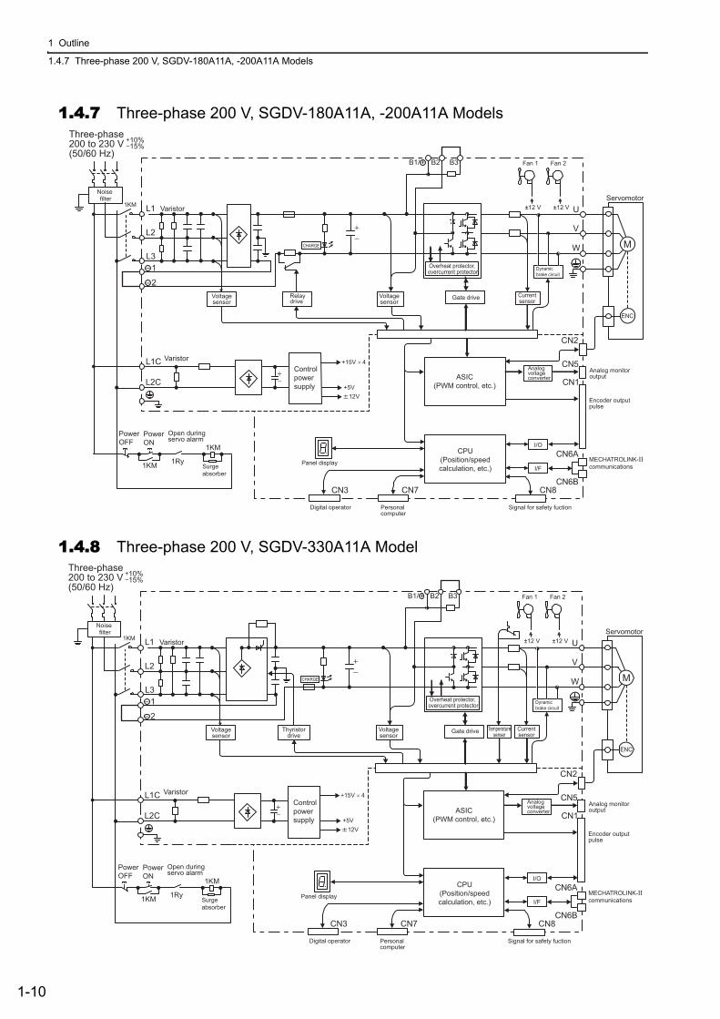
1.4.7 Three-phase 200 V, SGDV-180A11A, -200A11A Models
1.4.8 Three-phase 200 V, SGDV-330A11A Model
10%15%
1KM L1
B1/ B2 B3
L2
L31
2
L1C
L2C
U
V
W
1KM
1KM
1Ry
ENC
MCHARGE
+15V × 4
12V+5V
CN3 CN7 CN8
CN2
I/O
I/F
CN1
CN6A
CN6B
CN5
±12 V±12 VServomotor
Fan 2Fan 1
MECHATROLINK-II communications
Three-phase200 to 230 V(50/60 Hz)
Noisefilter
Varistor
Voltagesensor
Relaydrive
Varistor
Surgeabsorber
PowerOFF
PowerON
Open duringservo alarm
Controlpowersupply
CPU(Position/speedcalculation, etc.)
Panel display
Digital operator Personalcomputer
Signal for safety fuction
Encoder outputpulse
Analog monitoroutputASIC
(PWM control, etc.)
Analogvoltageconverter
Currentsensor
Dynamicbrake circuit
Gate driveVoltagesensor
Overheat protector, overcurrent protector
10%15%
1KM L1
B1/ B2 B3
L2
L31
2
L1C
L2C
U
V
W
1KM
1KM
1Ry
ENC
MCHARGE
+15V × 4
12V+5V
CN3 CN7 CN8
CN2
I/O
I/F
CN1
CN6A
CN6B
CN5
±12 V±12 VServomotor
Fan 2Fan 1
MECHATROLINK-II communications
Three-phase200 to 230 V(50/60 Hz)
Noisefilter
Varistor
Voltagesensor
Thyristordrive
Varistor
Surgeabsorber
PowerOFF
PowerON
Open duringservo alarm
Controlpowersupply
CPU(Position/speedcalculation, etc.)
Panel display
Digital operator Personalcomputer
Signal for safety fuction
Encoder outputpulse
Analog monitoroutputASIC
(PWM control, etc.)
Analogvoltageconverter
Currentsensor
Dynamicbrake circuit
Gate driveVoltagesensor
Overheat protector, overcurrent protector
Temperaturesenser
1.4 SERVOPACK Internal Block Diagrams
1-11
1
Ou
tlin
e
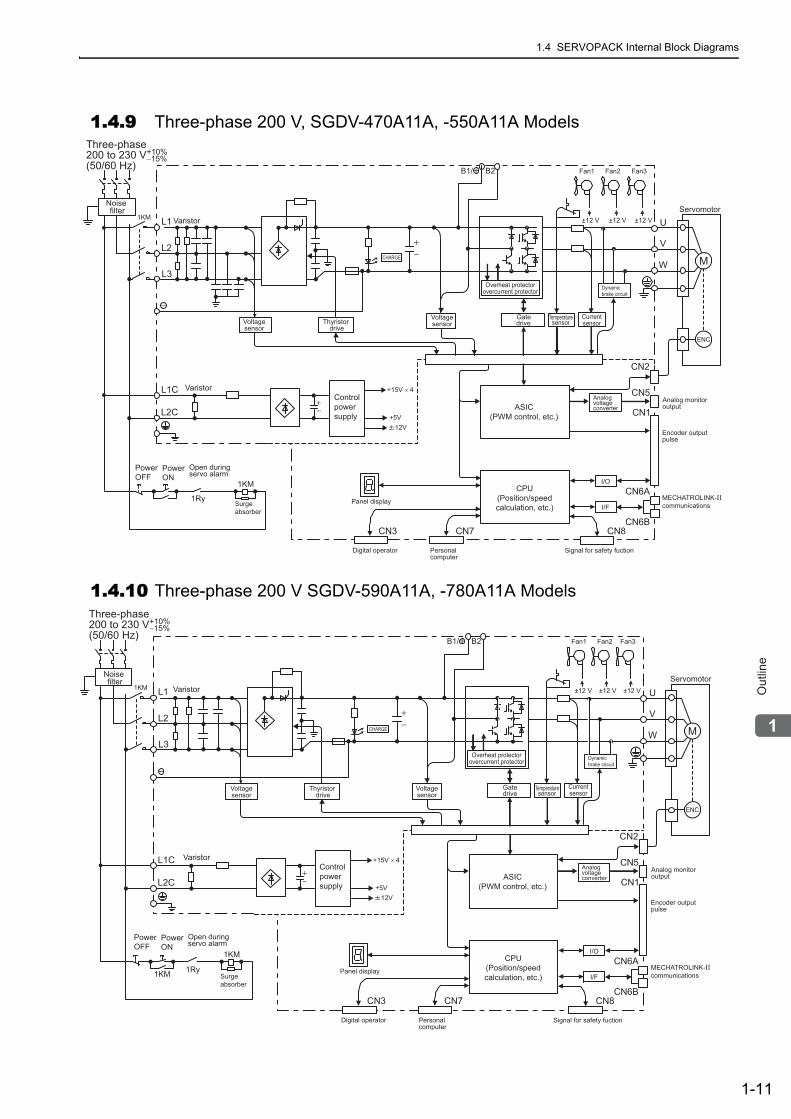
1.4.9 Three-phase 200 V, SGDV-470A11A, -550A11A Models
1.4.10 Three-phase 200 V SGDV-590A11A, -780A11A Models
1KM L1
B1/ B2
L2
L3
L1C
L2C
U
V
W
1KM
ENC
MCHARGE
+15V × 4
12V+5V
±12 V ±12 V±12 V
CN3 CN7 CN8
CN2
I/O
I/F
CN1
CN6A
CN6B
CN5
MECHATROLINK-II communications
CPU(Position/speedcalculation, etc.)
Panel display
Digital operator Personalcomputer
Signal for safety fuction
Encoder outputpulse
Analog monitoroutputASIC
(PWM control, etc.)
Analogvoltageconverter
Three-phase200 to 230 V(50/60 Hz)
+10%−15%
Noisefilter
Currentsensor
Dynamicbrake circuit
Surgeabsorber
PowerOFF
PowerON
Open duringservo alarm
Servomotor
Gatedrive
VoltagesensorVoltage
sensor
Varistor
Varistor
TemperaturesensorThyristor
drive
Fan1 Fan2 Fan3
Controlpowersupply
Overheat protectorovercurrent protector
1Ry
1KM L1
B1/ B2
L2
L3
L1C
L2C
U
V
W
1KM
1KM
1Ry
ENC
MCHARGE
+15V × 4
12V+5V
±12 V ±12 V±12 V
CN3 CN7 CN8
CN2
I/O
I/F
CN1
CN6A
CN6B
CN5
MECHATROLINK-II communications
CPU(Position/speedcalculation, etc.)
Panel display
Digital operator Personalcomputer
Signal for safety fuction
Encoder outputpulse
Analog monitoroutputASIC
(PWM control, etc.)
Analogvoltageconverter
Three-phase200 to 230 V(50/60 Hz)
+10%−15%
Noisefilter
Currentsensor
Dynamicbrake circuit
Surgeabsorber
PowerOFF
PowerON
Open duringservo alarm
Servomotor
Gatedrive
Voltagesensor
Voltagesensor
Varistor
Varistor
Temperaturesensor
Fan1 Fan2 Fan3
Controlpowersupply
Overheat protectorovercurrent protector
Thyristor drive
1 Outline
1.4.11 Three-phase 400 V, SGDV-1R9D11A, -3R5D11A, -5R4D11A Models
1-12
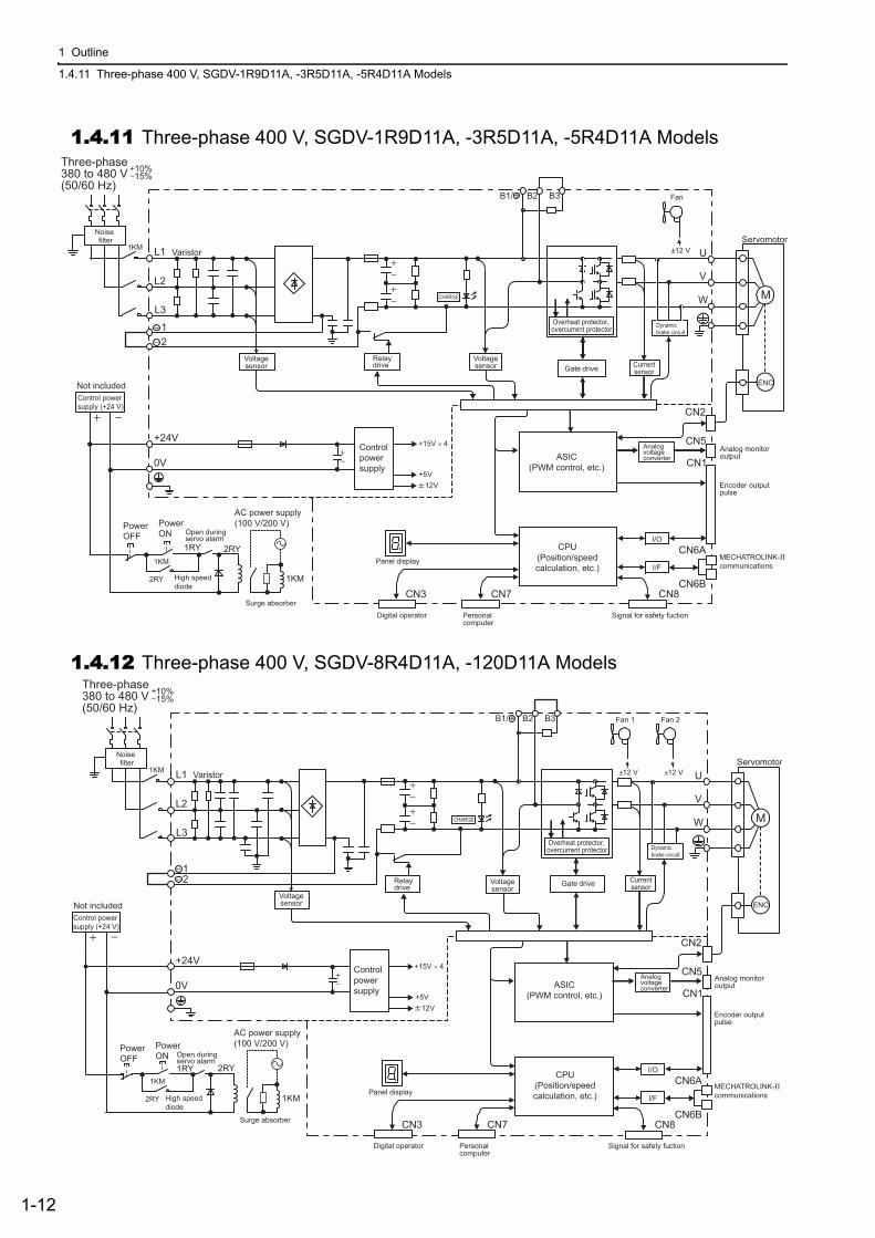
1.4.11 Three-phase 400 V, SGDV-1R9D11A, -3R5D11A, -5R4D11A Models
1.4.12 Three-phase 400 V, SGDV-8R4D11A, -120D11A Models
10%15%
1KM L1
B1/ B2 B3
L2
L3
12
+24V
0V
U
V
W
+15V × 4
12V
ENC
MCHARGE
+5V
CN3 CN7 CN8
CN2
I/O
I/F
CN1
CN6A
CN6B
CN5
1RY
±12 V
2RY
2RY
1KM
1KM
Servomotor
Fan
MECHATROLINK-II communications
Three-phase380 to 480 V(50/60 Hz)
Noisefilter
Varistor
Voltagesensor
Relaydrive
Surge absorber
PowerOFF
PowerON Open during
servo alarm
Controlpowersupply
CPU(Position/speedcalculation, etc.)
Panel display
Digital operator Personalcomputer
Signal for safety fuction
Encoder outputpulse
Analog monitoroutputASIC
(PWM control, etc.)
Analogvoltageconverter
Currentsensor
Dynamicbrake circuit
Gate driveVoltagesensor
Overheat protector, overcurrent protector
Not includedControl powersupply (+24 V)
High speeddiode
AC power supply (100 V/200 V)
10%15%
1KM L1
B1/ B2 B3
L2
L3
12
+24V
0V
U
V
W
+15V × 4
ENC
MCHARGE
±12 V ±12 V
12V+5V
2RY
1RY 2RY
1KM
1KM
CN3 CN7 CN8
CN2
I/O
I/F
CN1
CN6A
CN6B
CN5
Servomotor
Fan 2Fan 1
MECHATROLINK-II communications
Three-phase380 to 480 V(50/60 Hz)
Noisefilter
Varistor
Voltagesensor
Relaydrive
Surge absorber
PowerOFF
PowerON Open during
servo alarm
Controlpowersupply
CPU(Position/speedcalculation, etc.)Panel display
Digital operator Personalcomputer
Signal for safety fuction
Encoder outputpulse
Analog monitoroutputASIC
(PWM control, etc.)
Analogvoltageconverter
Currentsensor
Dynamicbrake circuit
Gate driveVoltagesensor
Overheat protector, overcurrent protector
Not includedControl powersupply (+24 V)
High speeddiode
AC power supply (100 V/200 V)
1.4 SERVOPACK Internal Block Diagrams
1-13
1
Ou
tlin
e
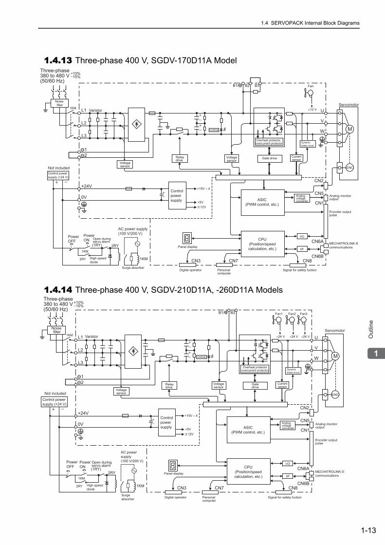
1.4.13 Three-phase 400 V, SGDV-170D11A Model
1.4.14 Three-phase 400 V, SGDV-210D11A, -260D11A Models
10%15%
1KM L1
B1/ B2 B3
L2
L3
12
+24V
0V
U
V
W
ENC
MCHARGE
+15V × 4
2RY
(1RY) 2RY
1KM
1KM
12V+5V
CN3 CN7 CN8
CN2
I/O
I/F
CN1
CN6A
CN6B
CN5
±12 VServomotor
Fan
MECHATROLINK-II communications
Three-phase380 to 480 V(50/60 Hz)
Noisefilter
Varistor
Voltagesensor
Relaydrive
Surge absorber
PowerOFF
PowerON Open during
servo alarm
Controlpowersupply
CPU(Position/speedcalculation, etc.)Panel display
Digital operator Personalcomputer
Signal for safety fuction
Encoder outputpulse
Analog monitoroutputASIC
(PWM control, etc.)
Analogvoltageconverter
Currentsensor
Dynamicbrake circuit
Gate driveVoltagesensor
Overheat protector, overcurrent protector
Not includedControl powersupply (+24 V)
High speeddiode
AC power supply (100 V/200 V)
1KM L1
B1/ B2
L2
L3
12
+24V
0V
U
V
W
ENC
MCHARGE
+15V × 4
2RY
2RY
1KM
1KM
12V+5V
+24 V +24 V +24 V
CN3 CN7 CN8
CN2
I/O
I/F
CN1
CN6A
CN6B
CN5
MECHATROLINK-II communications
CPU(Position/speedcalculation, etc.)
Panel display
Digital operator Personalcomputer
Signal for safety fuction
Encoder outputpulse
Analog monitoroutputASIC
(PWM control, etc.)
Analogvoltageconverter
Three-phase380 to 480 V(50/60 Hz)
+10%−15%
Noisefilter
Currentsensor
Dynamicbrake circuit
High speeddiode
PowerOFF
PowerON
Open duringservo alarm
Servomotor
Gatedrive
Voltagesensor
Voltagesensor
Varistor
Relaydrive
Controlpowersupply
Not includedControl powersupply (+24 V)
AC power supply (100 V/200 V)
Surgeabsorber
Overheat protectorovercurrent protector
Fan1 Fan2 Fan3
(1RY)
1 Outline
1.4.15 Three-phase 400 V SGDV-280D11A, -370D11A Models
1-14
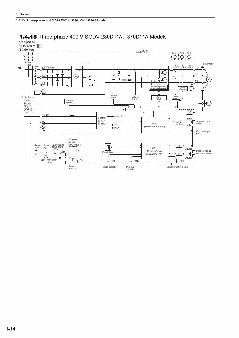
1.4.15 Three-phase 400 V SGDV-280D11A, -370D11A ModelsThree-phase380 to 480 V (50/60 Hz)
10%15%
1KM L1
B1/ B2
L2
L3
12
+24V
0V
U
V
W
ENC
MCHARGE
+15V × 4
2RY
2RY
1KM
1KM
Control Power Supply(+24 V)
Not included
12V+5V
+24 V +24 V +24 V
Noisefilter
Currentsensor
Dynamicbrake circuit
High speeddiode
PowerOFF
PowerON
Open duringservo alarm
Gatedrive
Voltagesensor
Voltagesensor
Varistor
Controlpowersupply
AC power supply (100 V/200 V)
Surgeabsorber
Overheat protectorovercurrent protector
Fan1 Fan2 Fan3
Thyristor drive
Servomotor
(1RY)
CN3 CN7 CN8
CN2
I/O
I/F
CN1
CN6A
CN6B
CN5
MECHATROLINK-II communications
CPU(Position/speedcalculation, etc.)
Panel display
Digital operator Personalcomputer
Signal for safety fuction
Encoder outputpulse
Analog monitoroutputASIC
(PWM control, etc.)
Analogvoltageconverter
1.5 Examples of Servo System Configurations
1-15
1
Ou
tlin
e
1.5 Examples of Servo System ConfigurationsThis section describes examples of basic servo system configuration.
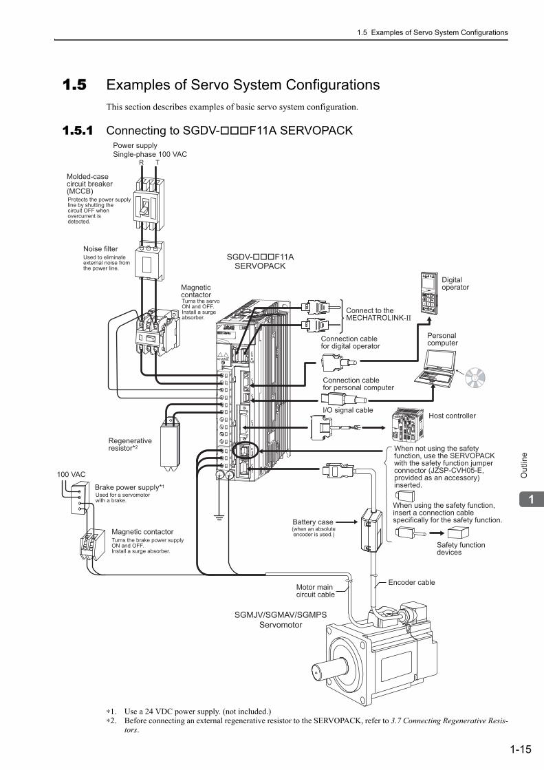
1.5.1 Connecting to SGDV- F11A SERVOPACK
∗1. Use a 24 VDC power supply. (not included.)∗2. Before connecting an external regenerative resistor to the SERVOPACK, refer to 3.7 Connecting Regenerative Resis-
tors.
Connect to the MECHATROLINK-II
SGDV-���F11ASERVOPACK
SGMJV/SGMAV/SGMPSServomotor
Power supplySingle-phase 100 VAC
R T
100 VAC
Noise filter
Molded-casecircuit breaker (MCCB)Protects the power supplyline by shutting thecircuit OFF whenovercurrent is detected.
Used to eliminateexternal noise fromthe power line.
Magnetic contactorTurns the servoON and OFF.Install a surgeabsorber.
Brake power supply*1
Magnetic contactor
Regenerativeresistor*2
Used for a servomotorwith a brake.
Turns the brake power supplyON and OFF.Install a surge absorber.
Motor maincircuit cable
Encoder cable
Battery case (when an absolute encoder is used.)
When not using the safetyfunction, use the SERVOPACKwith the safety function jumperconnector (JZSP-CVH05-E,provided as an accessory)inserted.
When using the safety function, insert a connection cablespecifically for the safety function.
Safety functiondevices
I/O signal cable
Connection cablefor digital operator
Connection cablefor personal computer
Digitaloperator
Personalcomputer
Host controller
1 Outline
1.5.2 Connecting to SGDV- A11A SERVOPACK
1-16
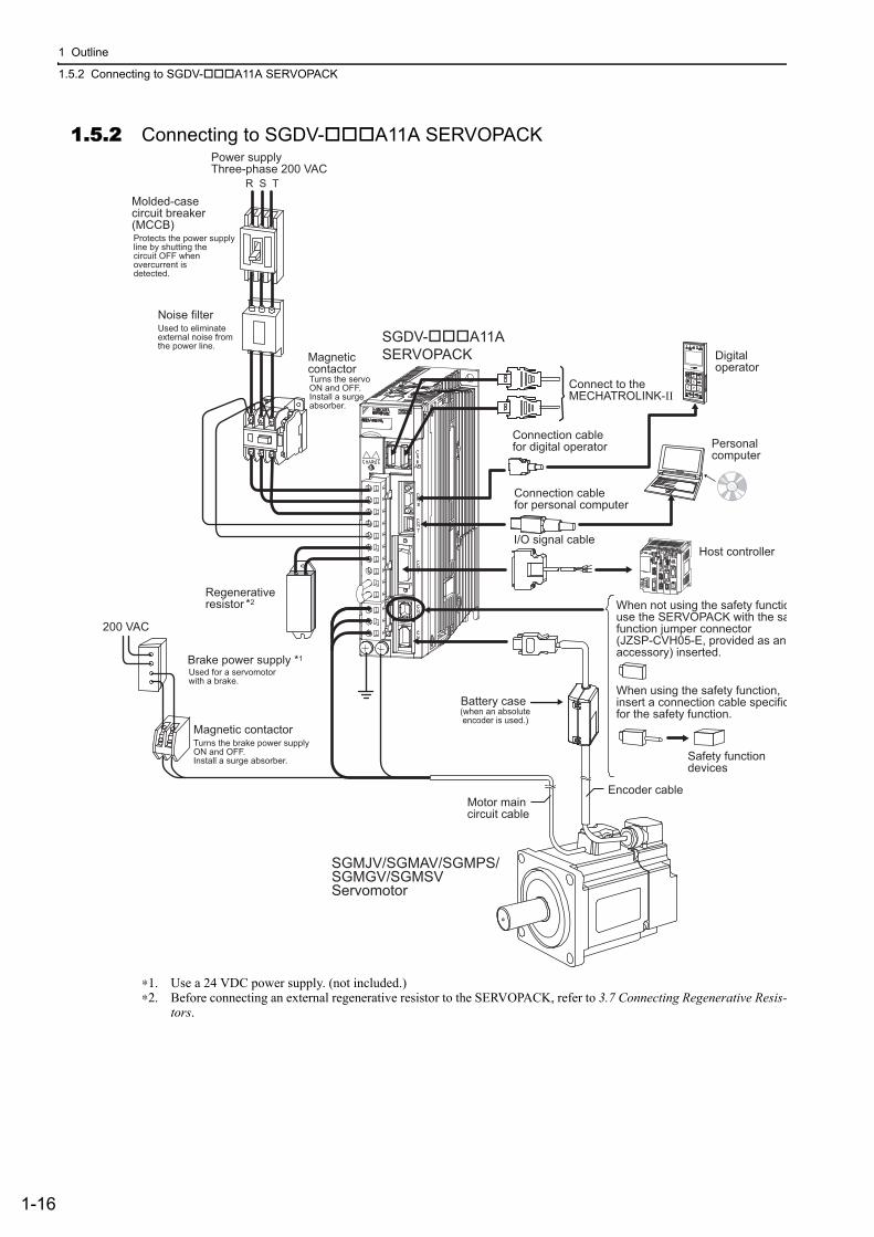
1.5.2 Connecting to SGDV- A11A SERVOPACK
∗1. Use a 24 VDC power supply. (not included.)∗2. Before connecting an external regenerative resistor to the SERVOPACK, refer to 3.7 Connecting Regenerative Resis-
tors.
Motor maincircuit cable
Encoder cable
Battery case
Regenerativeresistor
Noise filter
Molded-casecircuit breaker (MCCB)
Magnetic contactor
When not using the safety functiouse the SERVOPACK with the safunction jumper connector (JZSP-CVH05-E, provided as an accessory) inserted.
When using the safety function, insert a connection cable specificfor the safety function.
Safety functiondevices
I/O signal cable
SGDV-���A11A SERVOPACK
SGMJV/SGMAV/SGMPS/SGMGV/SGMSVServomotor
Power supplyThree-phase 200 VAC
R S T
Protects the power supplyline by shutting thecircuit OFF whenovercurrent is detected.
Used to eliminateexternal noise fromthe power line.
Turns the servoON and OFF.Install a surgeabsorber.
(when an absolute encoder is used.)
Connection cablefor digital operator
Connection cablefor personal computer
Digitaloperator
Personalcomputer
Connect to the MECHATROLINK-II
*2
Brake power supply *1
Magnetic contactor
Used for a servomotorwith a brake.
Turns the brake power supplyON and OFF.Install a surge absorber.
200 VAC
Host controller
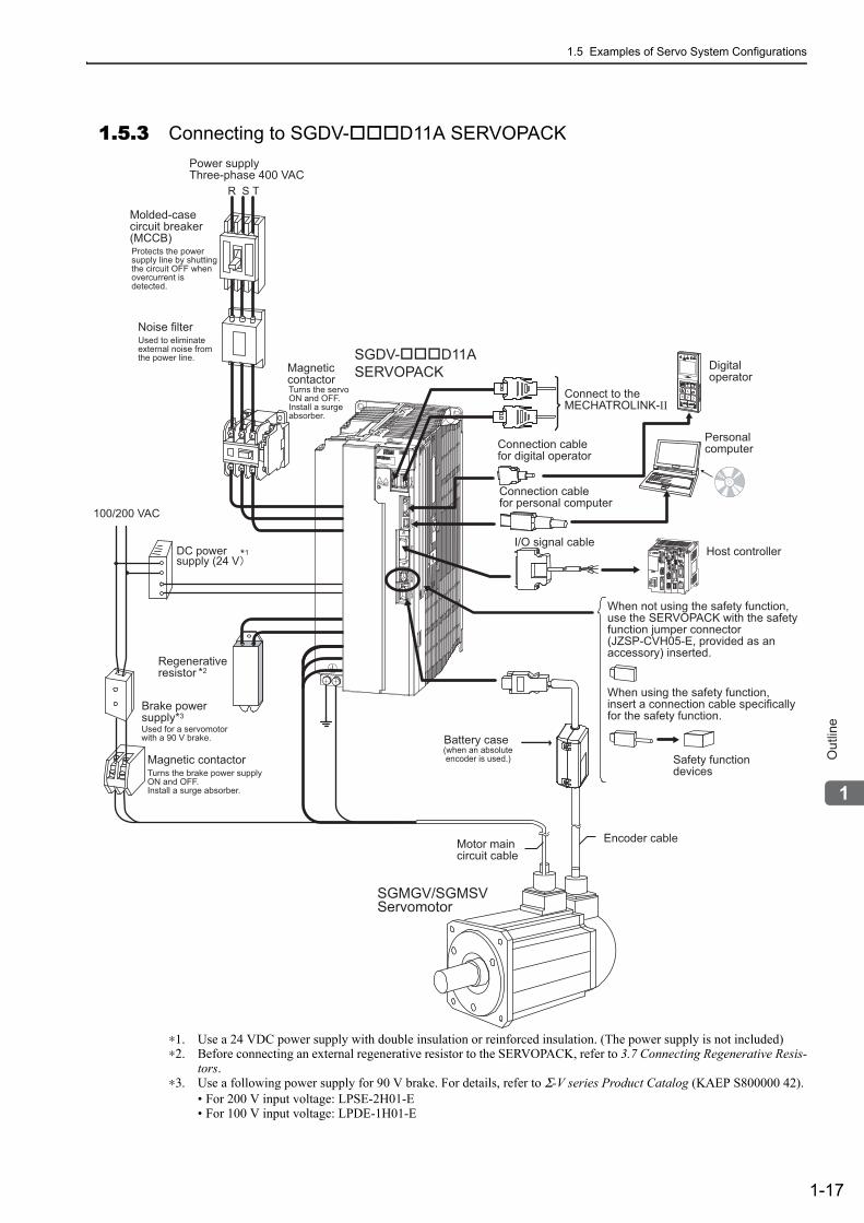
1.5 Examples of Servo System Configurations
1-17
1
Ou
tlin
e
1.5.3 Connecting to SGDV- D11A SERVOPACK
∗1. Use a 24 VDC power supply with double insulation or reinforced insulation. (The power supply is not included)∗2. Before connecting an external regenerative resistor to the SERVOPACK, refer to 3.7 Connecting Regenerative Resis-
tors.∗3. Use a following power supply for 90 V brake. For details, refer to Σ-V series Product Catalog (KAEP S800000 42).
• For 200 V input voltage: LPSE-2H01-E• For 100 V input voltage: LPDE-1H01-E
Battery case
Noise filter
Molded-casecircuit breaker (MCCB)
Magnetic contactor
I/O signal cable
Power supplyThree-phase 400 VAC
Protects the power supply line by shuttingthe circuit OFF whenovercurrent is detected.
Used to eliminateexternal noise fromthe power line.
Turns the servoON and OFF.Install a surgeabsorber.
(when an absolute encoder is used.)
Connection cablefor digital operator
Connection cablefor personal computer
Personalcomputer
Motor maincircuit cable
Encoder cable
SGMGV/SGMSV Servomotor
When not using the safety function, use the SERVOPACK with the safetyfunction jumper connector(JZSP-CVH05-E, provided as an accessory) inserted.
When using the safety function, insert a connection cable specificallyfor the safety function.
Safety functiondevices
SGDV-���D11A SERVOPACK
R S T
Digitaloperator
Connect to the MECHATROLINK-II
Brake powersupply*3
Magnetic contactorTurns the brake power supplyON and OFF.Install a surge absorber.
Used for a servomotorwith a 90 V brake.
Regenerativeresistor *2
DC powersupply (24 V
100/200 VAC
*1 Host controller
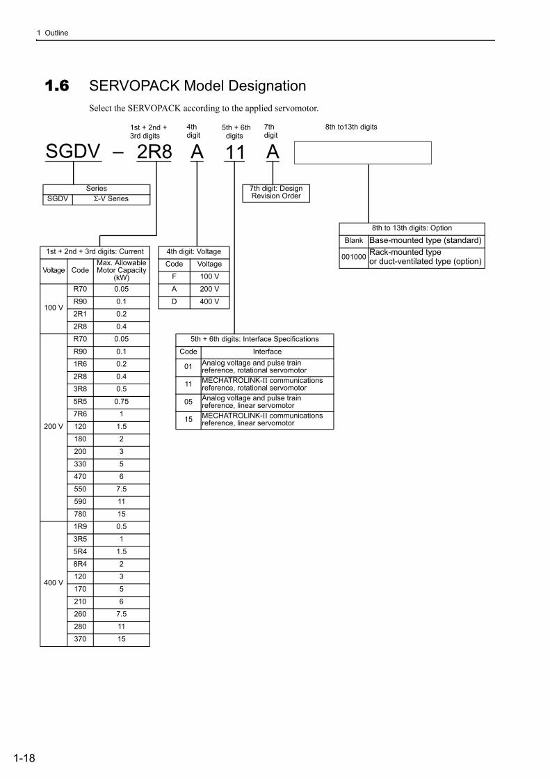
1 Outline
1-18
1.6 SERVOPACK Model DesignationSelect the SERVOPACK according to the applied servomotor.
SGDV
SeriesSGDV Σ-V Series
1st + 2nd + 3rd digits: Current
Voltage CodeMax. Allowable Motor Capacity
(kW)
100 V
R70 0.05
R90 0.1
2R1 0.2
2R8 0.4
200 V
R70 0.05
R90 0.1
1R6 0.2
2R8 0.4
3R8 0.5
5R5 0.75
7R6 1
120 1.5
180 2
200 3
330 5
470 6
550 7.5
590 11
780 15
400 V
1R9 0.5
3R5 1
5R4 1.5
8R4 2
120 3
170 5
210 6
260 7.5
280 11
370 15
4th digit: Voltage
Code Voltage
F 100 V
A 200 V
D 400 V
5th + 6th digits: Interface Specifications
Code Interface
01 Analog voltage and pulse train reference, rotational servomotor
11 MECHATROLINK-II communications reference, rotational servomotor
05 Analog voltage and pulse train reference, linear servomotor
15 MECHATROLINK-II communications reference, linear servomotor
8th to 13th digits: Option
Blank Base-mounted type (standard)
001000 Rack-mounted type or duct-ventilated type (option)
–
7th digit: Design Revision Order
1st + 2nd + 3rd digits
4thdigit
5th + 6th digits
7thdigit
2R8 A 11 A8th to13th digits
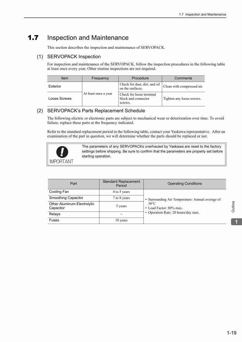
1.7 Inspection and Maintenance
1-19
1
Ou
tlin
e
1.7 Inspection and MaintenanceThis section describes the inspection and maintenance of SERVOPACK.
(1) SERVOPACK InspectionFor inspection and maintenance of the SERVOPACK, follow the inspection procedures in the following table at least once every year. Other routine inspections are not required.
(2) SERVOPACK’s Parts Replacement ScheduleThe following electric or electronic parts are subject to mechanical wear or deterioration over time. To avoid failure, replace these parts at the frequency indicated.
Refer to the standard replacement period in the following table, contact your Yaskawa representative. After an examination of the part in question, we will determine whether the parts should be replaced or not.
Item Frequency Procedure Comments
Exterior
At least once a year
Check for dust, dirt, and oil on the surfaces. Clean with compressed air.
Loose ScrewsCheck for loose terminal block and connector screws.
Tighten any loose screws.
The parameters of any SERVOPACKs overhauled by Yaskawa are reset to the factory settings before shipping. Be sure to confirm that the parameters are properly set before starting operation.
Part Standard Replacement Period Operating Conditions
Cooling Fan 4 to 5 years
• Surrounding Air Temperature: Annual average of 30°C
• Load Factor: 80% max.• Operation Rate: 20 hours/day max.
Smoothing Capacitor 7 to 8 years
Other Aluminum Electrolytic Capacitor 5 years
Relays −
Fuses 10 years
2-1
2P
an
el D
isp
lay a
nd
Op
era
tio
n o
f D
igita
l O
pe
rato
r
2Panel Display and
Operation of Digital Operator
2.1 Panel Display . . . . . . . . . . . . . . . . . . . . . . . . . . . . . . . . . . . . . . . . . . . . . .2-22.1.1 Status Display . . . . . . . . . . . . . . . . . . . . . . . . . . . . . . . . . . . . . . . . . . . . . . . . . . . . . . . 2-22.1.2 Alarm and Warning Display . . . . . . . . . . . . . . . . . . . . . . . . . . . . . . . . . . . . . . . . . . . . . 2-22.1.3 Hard Wire Base Block Display . . . . . . . . . . . . . . . . . . . . . . . . . . . . . . . . . . . . . . . . . . 2-22.1.4 Overtravel Display . . . . . . . . . . . . . . . . . . . . . . . . . . . . . . . . . . . . . . . . . . . . . . . . . . . . 2-2
2.2 Utility Function Mode (Fn ), Parameter Setting Mode (Pn ), Monitor Mode (Un ) . . . . . . . . . . . . . . . . . . . . . . . . . . . . . . . . . . . . .2-3
2.3 Utility Function Mode (Fn ) . . . . . . . . . . . . . . . . . . . . . . . . . . . . . . . .2-3
2.4 How to Read a Parameter Explanation . . . . . . . . . . . . . . . . . . . . . . . . . . .2-52.4.1 Explanation Method for Parameter Setting Type . . . . . . . . . . . . . . . . . . . . . . . . . . . . 2-52.4.2 Explanation Method for Function Selection Type . . . . . . . . . . . . . . . . . . . . . . . . . . . . 2-52.4.3 Explanation Method for Tuning Parameters . . . . . . . . . . . . . . . . . . . . . . . . . . . . . . . . 2-6
2.5 Parameter Setting Mode (Pn ) . . . . . . . . . . . . . . . . . . . . . . . . . . . . .2-72.5.1 Parameter Setting Mode for Parameter Setting Type . . . . . . . . . . . . . . . . . . . . . . . . . 2-72.5.2 Parameter Setting Mode for Function Selection Type . . . . . . . . . . . . . . . . . . . . . . . . . 2-9
2.6 Monitor Mode (Un ) . . . . . . . . . . . . . . . . . . . . . . . . . . . . . . . . . . . . 2-10
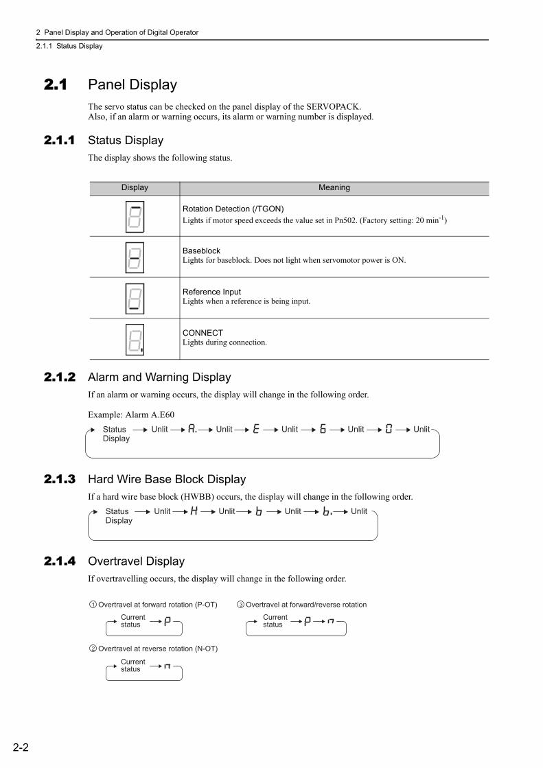
2 Panel Display and Operation of Digital Operator
2.1.1 Status Display
2-2
2.1 Panel DisplayThe servo status can be checked on the panel display of the SERVOPACK.Also, if an alarm or warning occurs, its alarm or warning number is displayed.
2.1.1 Status DisplayThe display shows the following status.
2.1.2 Alarm and Warning DisplayIf an alarm or warning occurs, the display will change in the following order.
Example: Alarm A.E60
2.1.3 Hard Wire Base Block DisplayIf a hard wire base block (HWBB) occurs, the display will change in the following order.
2.1.4 Overtravel DisplayIf overtravelling occurs, the display will change in the following order.
Display Meaning
Rotation Detection (/TGON)Lights if motor speed exceeds the value set in Pn502. (Factory setting: 20 min-1)
BaseblockLights for baseblock. Does not light when servomotor power is ON.
Reference Input Lights when a reference is being input.
CONNECT Lights during connection.
Status
Display
Unlit Unlit Unlit Unlit Unlit
StatusDisplay
Unlit Unlit Unlit Unlit
Overtravel at forward rotation (P-OT)
Currentstatus
Currentstatus
Currentstatus
1
Overtravel at reverse rotation (N-OT)2
Overtravel at forward/reverse rotation3
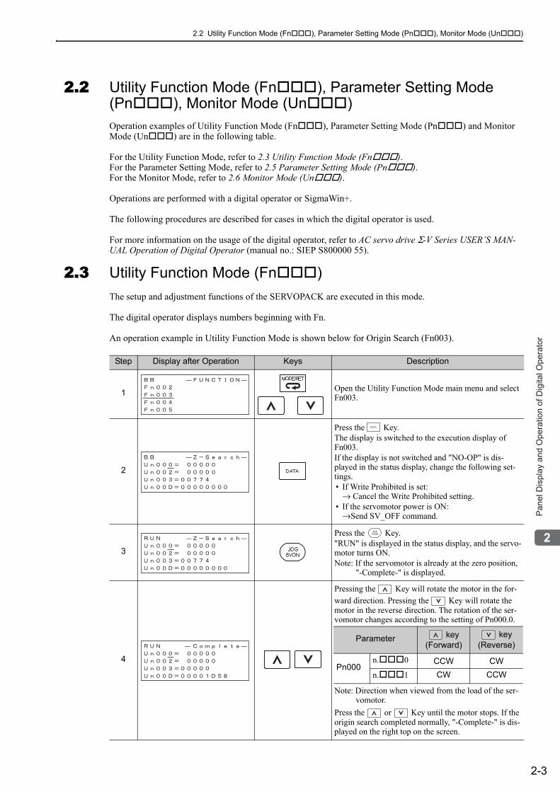
2.2 Utility Function Mode (Fn ), Parameter Setting Mode (Pn ), Monitor Mode (Un )
2-3
2P
an
el D
isp
lay a
nd
Op
era
tio
n o
f D
igita
l O
pe
rato
r
2.2 Utility Function Mode (Fn ), Parameter Setting Mode (Pn ), Monitor Mode (Un )Operation examples of Utility Function Mode (Fn ), Parameter Setting Mode (Pn ) and Monitor Mode (Un ) are in the following table.
For the Utility Function Mode, refer to 2.3 Utility Function Mode (Fn ).For the Parameter Setting Mode, refer to 2.5 Parameter Setting Mode (Pn ).For the Monitor Mode, refer to 2.6 Monitor Mode (Un ).
Operations are performed with a digital operator or SigmaWin+.
The following procedures are described for cases in which the digital operator is used.
For more information on the usage of the digital operator, refer to AC servo drive Σ-V Series USER’S MAN-UAL Operation of Digital Operator (manual no.: SIEP S800000 55).
2.3 Utility Function Mode (Fn )The setup and adjustment functions of the SERVOPACK are executed in this mode.
The digital operator displays numbers beginning with Fn.
An operation example in Utility Function Mode is shown below for Origin Search (Fn003).
Step Display after Operation Keys Description
1 Open the Utility Function Mode main menu and select Fn003.
2
Press the Key.The display is switched to the execution display of Fn003.If the display is not switched and "NO-OP" is dis-played in the status display, change the following set-tings. • If Write Prohibited is set:
→ Cancel the Write Prohibited setting.• If the servomotor power is ON:
→Send SV_OFF command.
3
Press the Key."RUN" is displayed in the status display, and the servo-motor turns ON.Note: If the servomotor is already at the zero position,
"-Complete-" is displayed.
4
Pressing the Key will rotate the motor in the for-ward direction. Pressing the Key will rotate the motor in the reverse direction. The rotation of the ser-vomotor changes according to the setting of Pn000.0.
Note: Direction when viewed from the load of the ser-vomotor.
Press the or Key until the motor stops. If the origin search completed normally, "-Complete-" is dis-played on the right top on the screen.
Parameter key(Forward)
key(Reverse)
Pn000n. 0 CCW CWn. 1 CW CCW

2 Panel Display and Operation of Digital Operator
2-4
5
When the origin search is completed, press the Key."BB" is displayed in the status display, and the servo-motor turns OFF. The display "-Complete-" changes to "-Z-Search-."
6Press the Key.The display returns to the Utility Function Mode main menu.This completes the operation.
Step Display after Operation Keys Description
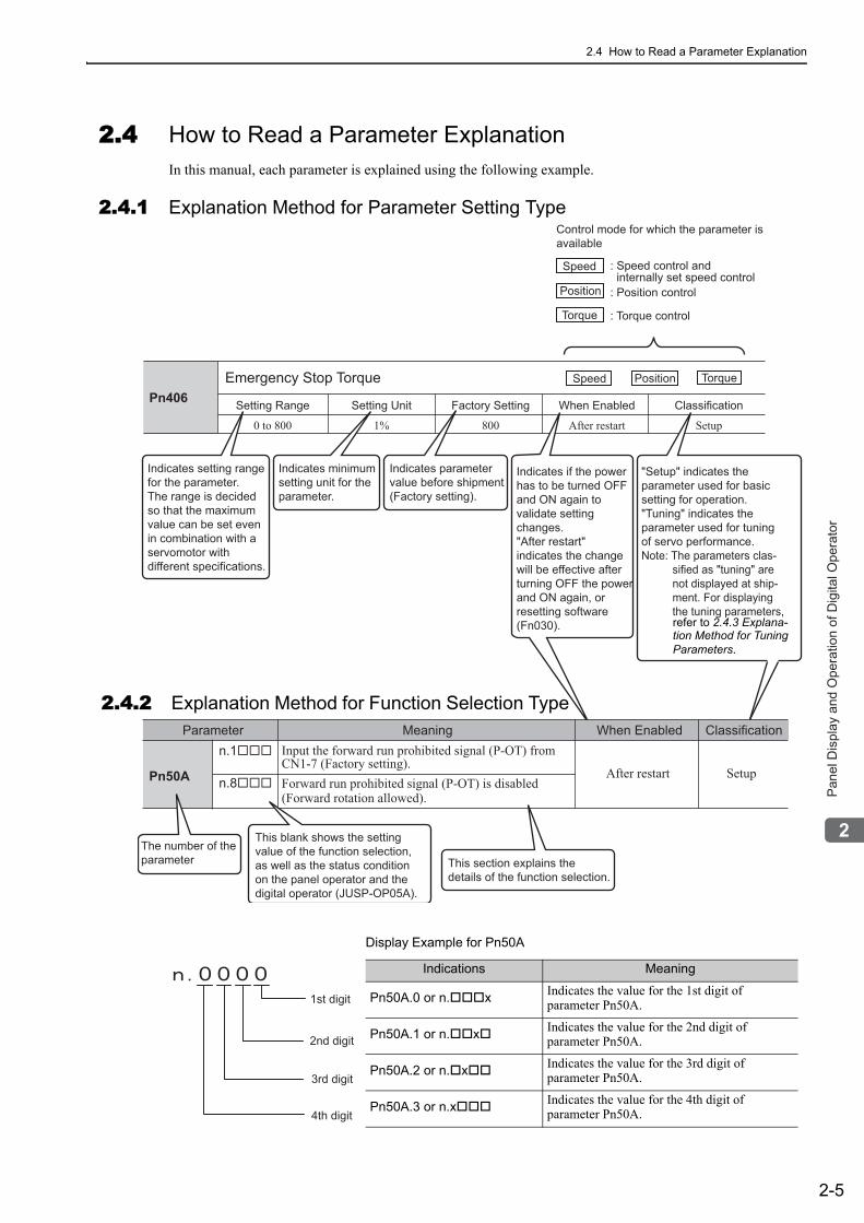
2.4 How to Read a Parameter Explanation
2-5
2P
an
el D
isp
lay a
nd
Op
era
tio
n o
f D
igita
l O
pe
rato
r
2.4 How to Read a Parameter ExplanationIn this manual, each parameter is explained using the following example.
2.4.1 Explanation Method for Parameter Setting Type
Pn406Emergency Stop Torque
Setting Range
0 to 800 1% 800 After restart
Setting Unit Factory Setting When Enabled
Setup
Classification
PositionSpeed Torque
Position
Torque
Control mode for which the parameter isavailable
Speed : Speed control and internally set speed control: Position control
: Torque control
Indicates setting range for the parameter.The range is decidedso that the maximumvalue can be set evenin combination with a servomotor withdifferent specifications.
Indicates minimumsetting unit for theparameter.
Indicates parametervalue before shipment (Factory setting).
Indicates if the powerhas to be turned OFFand ON again tovalidate settingchanges."After restart"indicates the changewill be effective afterturning OFF the powerand ON again, orresetting software(Fn030).
"Setup" indicates the parameter used for basicsetting for operation."Tuning" indicates the parameter used for tuningof servo performance.Note: The parameters clas- sified as "tuning" are not displayed at ship- ment. For displaying the tuning parameters, refer to (3) Explanation
Method for Tuning
Parameters.
Pn50A
n.1���
n.8���
Parameter Meaning ClassificationWhen EnabledInput the forward run prohibited signal (P-OT) fromCN1-7 (Factory setting).
SetupAfter restartForward run prohibited signal (P-OT) is disabled(Forward rotation allowed).
The number of the parameter This section explains the
details of the function selection.
This blank shows the setting value of the function selection, as well as the status condition on the panel operator and the digital operator (JUSP-OP05A).
2.4.2 Explanation Method for Function Selection Type
refer to 2.4.3 Explana-tion Method for Tuning Parameters.
Display Example for Pn50A
Indications Meaning
Pn50A.0 or n. x Indicates the value for the 1st digit of parameter Pn50A.
Pn50A.1 or n. x Indicates the value for the 2nd digit of parameter Pn50A.
Pn50A.2 or n. x Indicates the value for the 3rd digit ofparameter Pn50A.
Pn50A.3 or n.x Indicates the value for the 4th digit of parameter Pn50A.
1st digit
2nd digit
3rd digit
4th digit

2 Panel Display and Operation of Digital Operator
2.4.3 Explanation Method for Tuning Parameters
2-6
2.4.3 Explanation Method for Tuning ParametersOnly setup parameters are displayed at shipment. To display tuning parameters, change the following parame-ter.
Application Function Selection Switch B
Parameter Meaning When Enabled Classification
Pn00Bn. 0 Displays only setup parameters. (Factory setting)
After restart Setupn. 1 Displays all parameters.
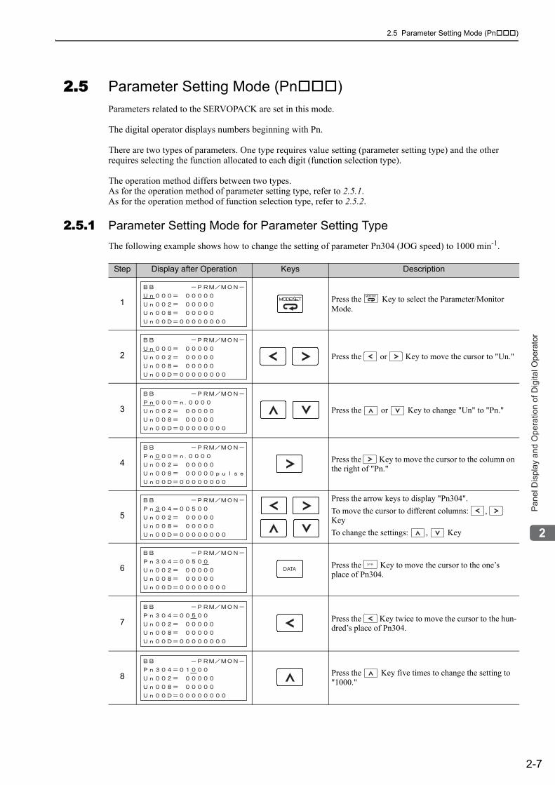
2.5 Parameter Setting Mode (Pn )
2-7
2P
an
el D
isp
lay a
nd
Op
era
tio
n o
f D
igita
l O
pe
rato
r
2.5 Parameter Setting Mode (Pn )Parameters related to the SERVOPACK are set in this mode.
The digital operator displays numbers beginning with Pn.
There are two types of parameters. One type requires value setting (parameter setting type) and the other requires selecting the function allocated to each digit (function selection type).
The operation method differs between two types.As for the operation method of parameter setting type, refer to 2.5.1.As for the operation method of function selection type, refer to 2.5.2.
2.5.1 Parameter Setting Mode for Parameter Setting TypeThe following example shows how to change the setting of parameter Pn304 (JOG speed) to 1000 min-1.
Step Display after Operation Keys Description
1 Press the Key to select the Parameter/Monitor Mode.
2 Press the or Key to move the cursor to "Un."
3 Press the or Key to change "Un" to "Pn."
4 Press the Key to move the cursor to the column on the right of "Pn."
5
Press the arrow keys to display "Pn304".To move the cursor to different columns: , KeyTo change the settings: , Key
6 Press the Key to move the cursor to the one’s place of Pn304.
7 Press the Key twice to move the cursor to the hun-dred’s place of Pn304.
8 Press the Key five times to change the setting to "1000."

2 Panel Display and Operation of Digital Operator
2.5.1 Parameter Setting Mode for Parameter Setting Type
2-8
9 Press the Key to write the settings.
Step Display after Operation Keys Description
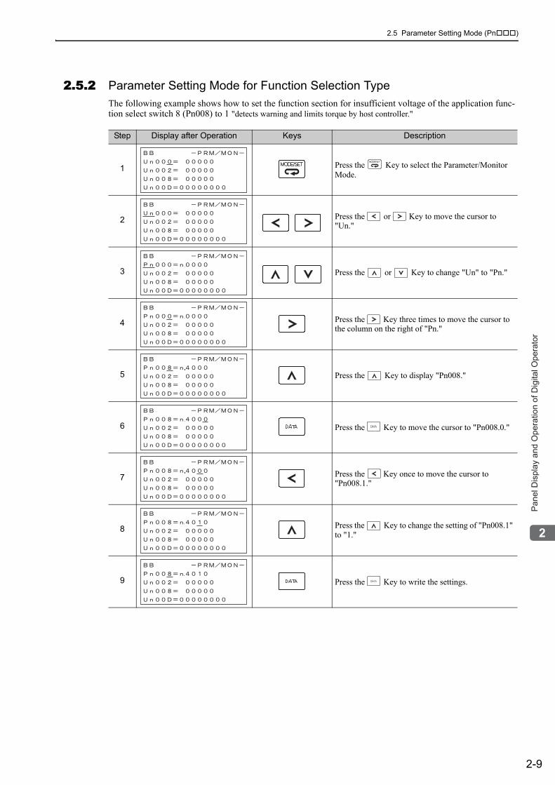
2.5 Parameter Setting Mode (Pn )
2-9
2P
an
el D
isp
lay a
nd
Op
era
tio
n o
f D
igita
l O
pe
rato
r
2.5.2 Parameter Setting Mode for Function Selection TypeThe following example shows how to set the function section for insufficient voltage of the application func-tion select switch 8 (Pn008) to 1 "detects warning and limits torque by host controller."
Step Display after Operation Keys Description
1 Press the Key to select the Parameter/Monitor Mode.
2 Press the or Key to move the cursor to "Un."
3 Press the or Key to change "Un" to "Pn."
4 Press the Key three times to move the cursor to the column on the right of "Pn."
5 Press the Key to display "Pn008."
6 Press the Key to move the cursor to "Pn008.0."
7 Press the Key once to move the cursor to "Pn008.1."
8 Press the Key to change the setting of "Pn008.1" to "1."
9 Press the Key to write the settings.
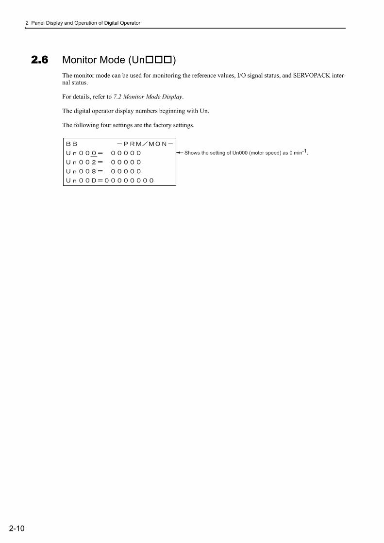
2 Panel Display and Operation of Digital Operator
2-10
2.6 Monitor Mode (Un )The monitor mode can be used for monitoring the reference values, I/O signal status, and SERVOPACK inter-nal status.
For details, refer to 7.2 Monitor Mode Display.
The digital operator display numbers beginning with Un.
The following four settings are the factory settings.
Shows the setting of Un000 (motor speed) as 0 min-1
.
3-1
3
Wirin
g a
nd
Co
nn
ectio
n
3Wiring and Connection
3.1 Main Circuit Wiring . . . . . . . . . . . . . . . . . . . . . . . . . . . . . . . . . . . . . . . . . .3-23.1.1 Names and Functions of Main Circuit Terminals . . . . . . . . . . . . . . . . . . . . . . . . . . . . . 3-33.1.2 SERVOPACK Main Circuit Wire Size . . . . . . . . . . . . . . . . . . . . . . . . . . . . . . . . . . . . . 3-43.1.3 Typical Main Circuit Wiring Examples . . . . . . . . . . . . . . . . . . . . . . . . . . . . . . . . . . . . . 3-63.1.4 General Precautions for Wiring . . . . . . . . . . . . . . . . . . . . . . . . . . . . . . . . . . . . . . . . . 3-103.1.5 Precautions When Using the SERVOPACK with a DC Power Input . . . . . . . . . . . . . 3-113.1.6 Precautions when Using the SERVOPACK with Single-phase, 200 V Power Input . 3-133.1.7 Precautions When Using More Than One SERVOPACK . . . . . . . . . . . . . . . . . . . . . 3-16
3.2 I/O Signal Connections . . . . . . . . . . . . . . . . . . . . . . . . . . . . . . . . . . . . . .3-173.2.1 I/O Signal (CN1) Names and Functions . . . . . . . . . . . . . . . . . . . . . . . . . . . . . . . . . . 3-173.2.2 I/O Signal Connector (CN1) Terminal Layout . . . . . . . . . . . . . . . . . . . . . . . . . . . . . . 3-183.2.3 Safety Function Signal (CN8) Names and Functions . . . . . . . . . . . . . . . . . . . . . . . . 3-183.2.4 Example of I/O Signal Connections . . . . . . . . . . . . . . . . . . . . . . . . . . . . . . . . . . . . . 3-19
3.3 I/O Signal Allocations . . . . . . . . . . . . . . . . . . . . . . . . . . . . . . . . . . . . . . . 3-203.3.1 Input Signal Allocations . . . . . . . . . . . . . . . . . . . . . . . . . . . . . . . . . . . . . . . . . . . . . . . 3-203.3.2 Output Signal Allocation . . . . . . . . . . . . . . . . . . . . . . . . . . . . . . . . . . . . . . . . . . . . . . 3-22
3.4 Examples of Connection to Host Controller . . . . . . . . . . . . . . . . . . . . . .3-233.4.1 Sequence Input Circuits . . . . . . . . . . . . . . . . . . . . . . . . . . . . . . . . . . . . . . . . . . . . . . 3-233.4.2 Sequence Output Circuits . . . . . . . . . . . . . . . . . . . . . . . . . . . . . . . . . . . . . . . . . . . . . 3-25
3.5 Wiring MECHATROLINK-II Communications . . . . . . . . . . . . . . . . . . . . . 3-27
3.6 Examples of Encoder Connection . . . . . . . . . . . . . . . . . . . . . . . . . . . . . . 3-283.6.1 Connection Example of an Encoder . . . . . . . . . . . . . . . . . . . . . . . . . . . . . . . . . . . . . 3-283.6.2 CN2 Encoder Connector Terminal Layout . . . . . . . . . . . . . . . . . . . . . . . . . . . . . . . . . 3-29
3.7 Connecting Regenerative Resistors . . . . . . . . . . . . . . . . . . . . . . . . . . . .3-303.7.1 Connecting Regenerative Resistors . . . . . . . . . . . . . . . . . . . . . . . . . . . . . . . . . . . . . 3-303.7.2 Setting Regenerative Resistor Capacity . . . . . . . . . . . . . . . . . . . . . . . . . . . . . . . . . . 3-31
3.8 Noise Control and Measures for Harmonic Suppression . . . . . . . . . . . .3-323.8.1 Wiring for Noise Control . . . . . . . . . . . . . . . . . . . . . . . . . . . . . . . . . . . . . . . . . . . . . . 3-323.8.2 Precautions on Connecting Noise Filter . . . . . . . . . . . . . . . . . . . . . . . . . . . . . . . . . . 3-343.8.3 Connecting AC/DC Reactor for Harmonic Suppression . . . . . . . . . . . . . . . . . . . . . . 3-36

3 Wiring and Connection
3-2
3.1 Main Circuit WiringThe names, specifications, and functions of the main circuit terminals are given on the following page.
Also this section describes the general precautions for wiring and precautions under special environments.
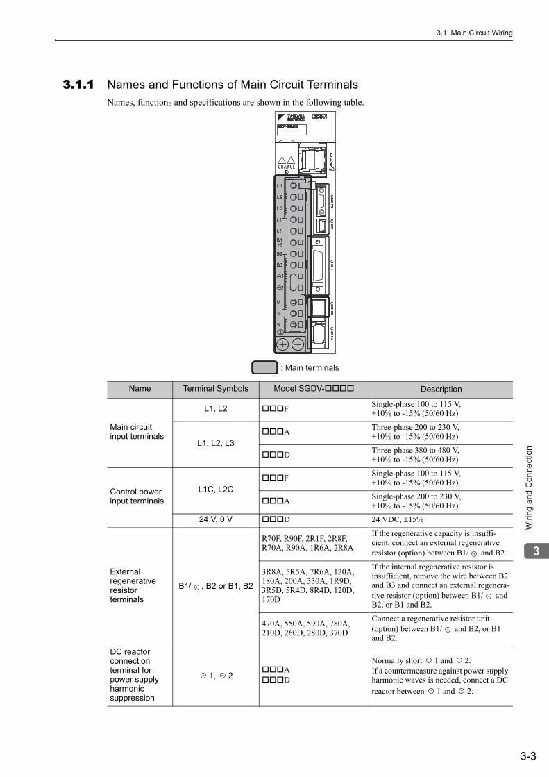
3.1 Main Circuit Wiring
3-3
3
Wirin
g a
nd
Co
nn
ectio
n
3.1.1 Names and Functions of Main Circuit TerminalsNames, functions and specifications are shown in the following table.
: Main terminals
Name Terminal Symbols Model SGDV- Description
Main circuit input terminals
L1, L2 F Single-phase 100 to 115 V,+10% to -15% (50/60 Hz)
L1, L2, L3A Three-phase 200 to 230 V,
+10% to -15% (50/60 Hz)
D Three-phase 380 to 480 V,+10% to -15% (50/60 Hz)
Control power input terminals
L1C, L2CF Single-phase 100 to 115 V,
+10% to -15% (50/60 Hz)
A Single-phase 200 to 230 V,+10% to -15% (50/60 Hz)
24 V, 0 V D 24 VDC, ±15%
External regenerative resistor terminals
B1/ , B2 or B1, B2
R70F, R90F, 2R1F, 2R8F, R70A, R90A, 1R6A, 2R8A
If the regenerative capacity is insuffi-cient, connect an external regenerative resistor (option) between B1/ and B2.
3R8A, 5R5A, 7R6A, 120A, 180A, 200A, 330A, 1R9D, 3R5D, 5R4D, 8R4D, 120D, 170D
If the internal regenerative resistor is insufficient, remove the wire between B2 and B3 and connect an external regenera-tive resistor (option) between B1/ and B2, or B1 and B2.
470A, 550A, 590A, 780A, 210D, 260D, 280D, 370D
Connect a regenerative resistor unit (option) between B1/ and B2, or B1 and B2.
DC reactor connection terminal for power supply harmonic suppression
1, 2AD
Normally short 1 and 2. If a countermeasure against power supply harmonic waves is needed, connect a DC reactor between 1 and 2.
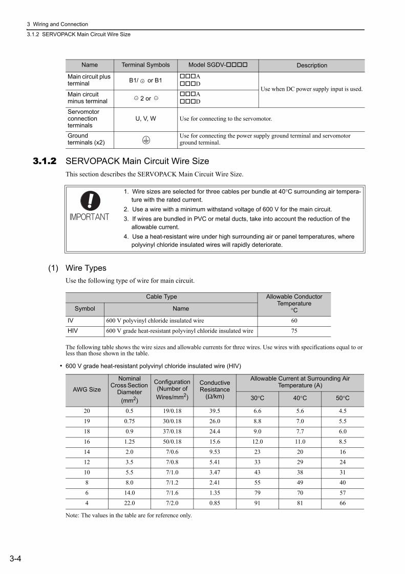
3 Wiring and Connection
3.1.2 SERVOPACK Main Circuit Wire Size
3-4
3.1.2 SERVOPACK Main Circuit Wire SizeThis section describes the SERVOPACK Main Circuit Wire Size.
(1) Wire TypesUse the following type of wire for main circuit.
The following table shows the wire sizes and allowable currents for three wires. Use wires with specifications equal to or less than those shown in the table.
• 600 V grade heat-resistant polyvinyl chloride insulated wire (HIV)
Note: The values in the table are for reference only.
Main circuit plus terminal B1/ or B1
AD
Use when DC power supply input is used.Main circuit minus terminal 2 or
AD
Servomotor connection terminals
U, V, W Use for connecting to the servomotor.
Ground terminals (x2)
Use for connecting the power supply ground terminal and servomotor ground terminal.
Name Terminal Symbols Model SGDV- Description
1. Wire sizes are selected for three cables per bundle at 40°C surrounding air tempera-ture with the rated current.
2. Use a wire with a minimum withstand voltage of 600 V for the main circuit.3. If wires are bundled in PVC or metal ducts, take into account the reduction of the
allowable current.4. Use a heat-resistant wire under high surrounding air or panel temperatures, where
polyvinyl chloride insulated wires will rapidly deteriorate.
Cable Type Allowable Conductor Temperature
°CSymbol Name
IV 600 V polyvinyl chloride insulated wire 60
HIV 600 V grade heat-resistant polyvinyl chloride insulated wire 75
AWG Size
Nominal Cross Section
Diameter (mm2)
Configuration(Number of Wires/mm2)
Conductive Resistance
(Ω/km)
Allowable Current at Surrounding Air Temperature (A)
30°C 40°C 50°C
20 0.5 19/0.18 39.5 6.6 5.6 4.5
19 0.75 30/0.18 26.0 8.8 7.0 5.5
18 0.9 37/0.18 24.4 9.0 7.7 6.0
16 1.25 50/0.18 15.6 12.0 11.0 8.5
14 2.0 7/0.6 9.53 23 20 16
12 3.5 7/0.8 5.41 33 29 24
10 5.5 7/1.0 3.47 43 38 31
8 8.0 7/1.2 2.41 55 49 40
6 14.0 7/1.6 1.35 79 70 57
4 22.0 7/2.0 0.85 91 81 66
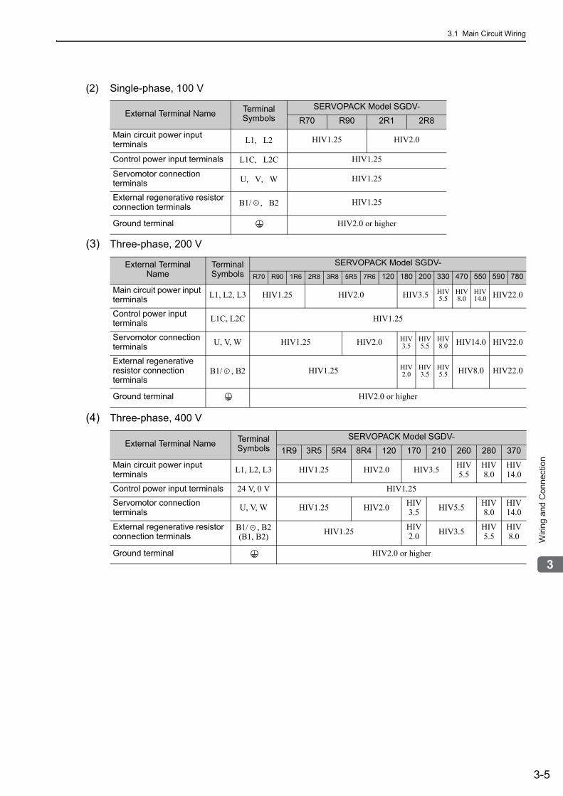
3.1 Main Circuit Wiring
3-5
3
Wirin
g a
nd
Co
nn
ectio
n
(2) Single-phase, 100 V
(3) Three-phase, 200 V
(4) Three-phase, 400 V
External Terminal Name Terminal Symbols
SERVOPACK Model SGDV-
R70 R90 2R1 2R8
Main circuit power input terminals L1,L2 HIV1.25 HIV2.0
Control power input terminals L1C,L2C HIV1.25
Servomotor connection terminals U,V,W HIV1.25
External regenerative resistor connection terminals B1/ ,B2 HIV1.25
Ground terminal HIV2.0 or higher
External Terminal Name
Terminal Symbols
SERVOPACK Model SGDV-R70 R90 1R6 2R8 3R8 5R5 7R6 120 180 200 330 470 550 590 780
Main circuit power input terminals L1, L2, L3 HIV1.25 HIV2.0 HIV3.5 HIV
5.5HIV8.0
HIV14.0 HIV22.0
Control power input terminals L1C, L2C HIV1.25
Servomotor connection terminals U, V, W HIV1.25 HIV2.0 HIV
3.5HIV5.5
HIV8.0 HIV14.0 HIV22.0
External regenerative resistor connection terminals
B1/ , B2 HIV1.25 HIV2.0
HIV3.5
HIV5.5 HIV8.0 HIV22.0
Ground terminal HIV2.0 or higher
External Terminal Name Terminal Symbols
SERVOPACK Model SGDV-
1R9 3R5 5R4 8R4 120 170 210 260 280 370
Main circuit power input terminals L1, L2, L3 HIV1.25 HIV2.0 HIV3.5 HIV
5.5HIV8.0
HIV14.0
Control power input terminals 24 V, 0 V HIV1.25
Servomotor connection terminals U, V, W HIV1.25 HIV2.0 HIV
3.5 HIV5.5 HIV8.0
HIV14.0
External regenerative resistor connection terminals
B1/ , B2(B1, B2) HIV1.25 HIV
2.0 HIV3.5 HIV5.5
HIV8.0
Ground terminal HIV2.0 or higher
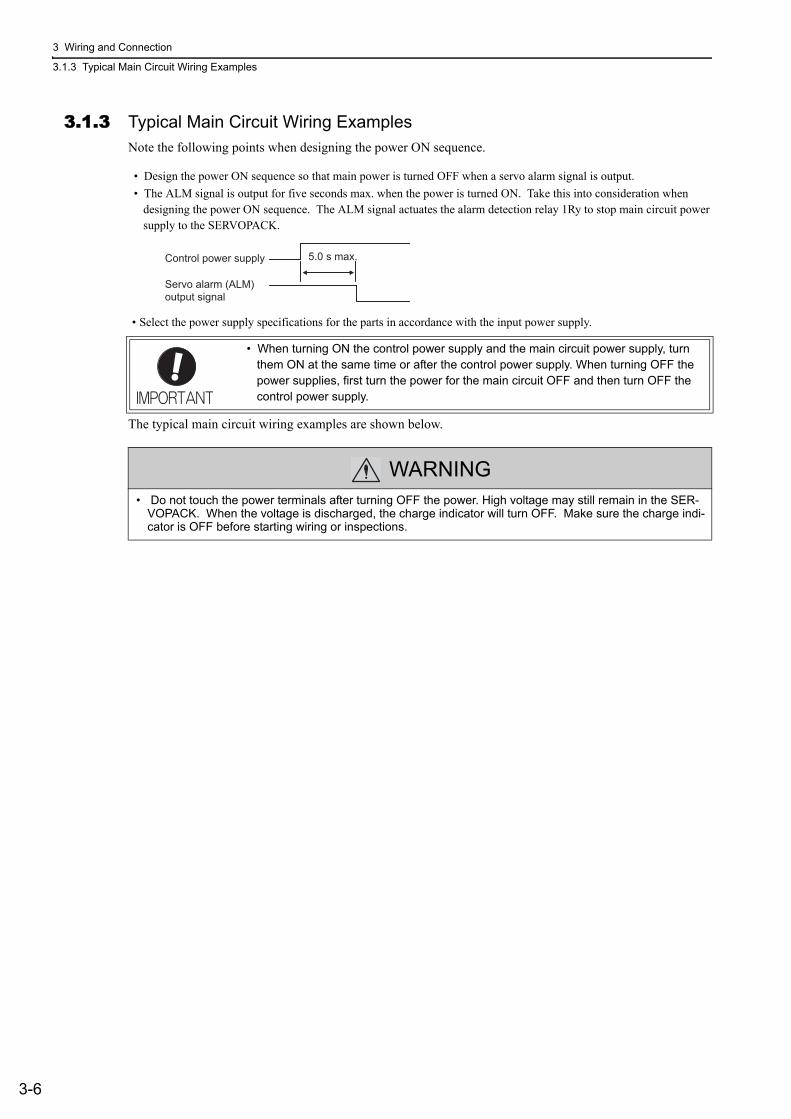
3 Wiring and Connection
3.1.3 Typical Main Circuit Wiring Examples
3-6
3.1.3 Typical Main Circuit Wiring ExamplesNote the following points when designing the power ON sequence.
• Design the power ON sequence so that main power is turned OFF when a servo alarm signal is output.• The ALM signal is output for five seconds max. when the power is turned ON. Take this into consideration when
designing the power ON sequence. The ALM signal actuates the alarm detection relay 1Ry to stop main circuit power supply to the SERVOPACK.
• Select the power supply specifications for the parts in accordance with the input power supply.
The typical main circuit wiring examples are shown below.
• When turning ON the control power supply and the main circuit power supply, turn them ON at the same time or after the control power supply. When turning OFF the power supplies, first turn the power for the main circuit OFF and then turn OFF the control power supply.
WARNING• Do not touch the power terminals after turning OFF the power. High voltage may still remain in the SER-
VOPACK. When the voltage is discharged, the charge indicator will turn OFF. Make sure the charge indi-cator is OFF before starting wiring or inspections.
Control power supply
Servo alarm (ALM)
output signal
5.0 s max.
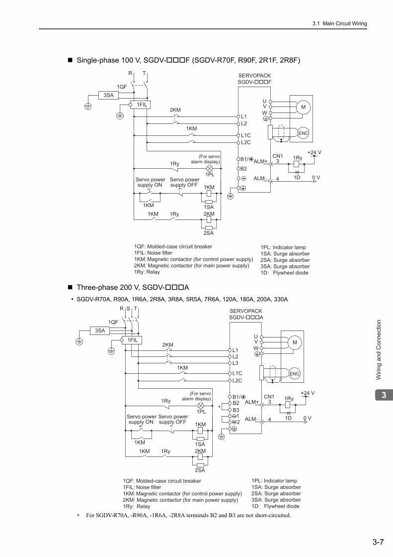
3.1 Main Circuit Wiring
3-7
3
Wirin
g a
nd
Co
nn
ectio
n
Single-phase 100 V, SGDV- F (SGDV-R70F, R90F, 2R1F, 2R8F)
Three-phase 200 V, SGDV- A• SGDV-R70A, R90A, 1R6A, 2R8A, 3R8A, 5R5A, 7R6A, 120A, 180A, 200A, 330A
∗ For SGDV-R70A, -R90A, -1R6A, -2R8A terminals B2 and B3 are not short-circuited.
1PL: Indicator lamp1SA: Surge absorber2SA: Surge absorber3SA: Surge absorber1D: Flywheel diode
1QF: Molded-case circuit breaker1FIL: Noise filter1KM: Magnetic contactor (for control power supply)2KM: Magnetic contactor (for main power supply)1Ry: Relay
L1
ENC
SERVOPACKSGDV-���F
UVW
M
0 V
1RyALM+
ALM−
3
4 1D
2KM
1KM
B2
L2
CN1
1QF
R T
1FIL
+24 VB1/
3SA
(For servoalarm display)1Ry
1PL
supply ON 1KM
2KM1SA
Servo powersupply OFFServo power
1KM1Ry1KM
2SA
L1CL2C
1PL: Indicator lamp1SA: Surge absorber2SA: Surge absorber3SA: Surge absorber1D: Flywheel diode
1QF: Molded-case circuit breaker1FIL: Noise filter1KM: Magnetic contactor (for control power supply)2KM: Magnetic contactor (for main power supply)1Ry: Relay
2KML1
ENC
SERVOPACKSGDV-���A
UVW
M
0 V
1RyALM+
ALM−
3
4 1D
B2B3
L2
CN1
1KML1C
L3
L2C
1QF
R S T
+24 V
12
3SA
∗
B1/1Ry
1PL
1KM
2KM1SA
1Ry1KM
2SA
1KM
(For servoalarm display)
supply ONServo power
supply OFFServo power
1FIL
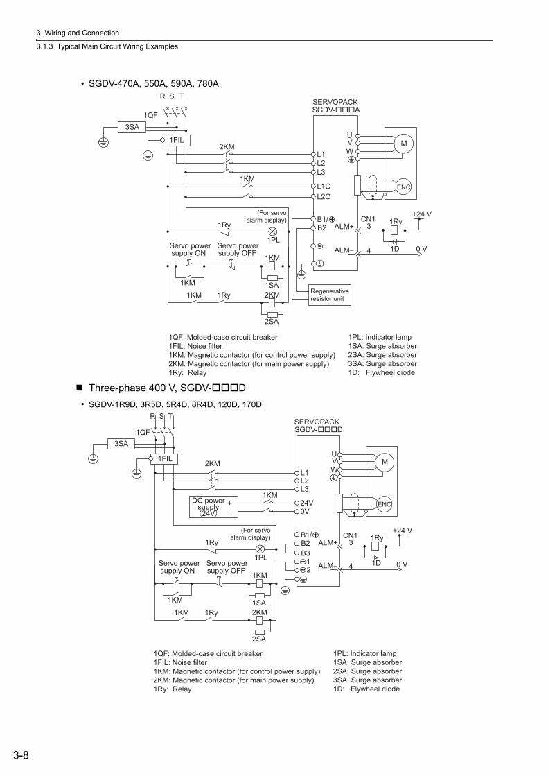
3 Wiring and Connection
3.1.3 Typical Main Circuit Wiring Examples
3-8
• SGDV-470A, 550A, 590A, 780A
Three-phase 400 V, SGDV- D• SGDV-1R9D, 3R5D, 5R4D, 8R4D, 120D, 170D
2KML1
ENC
SGDV-���A
UVW
M
0 V
1RyALM+
ALM−
3
4 1D
B2
L2
CN1
1KML1C
L3
L2C
1QF
R S T
1FIL
+24 V
3SA
B1/1Ry
1PL
1KM
2KM1SA
1Ry1KM
2SA
1KMRegenerative resistor unit
(For servoalarm display)
supply ONServo power
supply OFFServo power
SERVOPACK
1QF: Molded-case circuit breaker1FIL: Noise filter1KM: Magnetic contactor (for control power supply)2KM: Magnetic contactor (for main power supply)1Ry: Relay
1PL: Indicator lamp1SA: Surge absorber2SA: Surge absorber3SA: Surge absorber1D: Flywheel diode
1QF: Molded-case circuit breaker1FIL: Noise filter1KM: Magnetic contactor (for control power supply)2KM: Magnetic contactor (for main power supply)1Ry: Relay
1PL: Indicator lamp1SA: Surge absorber2SA: Surge absorber3SA: Surge absorber1D: Flywheel diode
ENC
SGDV-���D
UVW
M
0 V
1RyALM+
ALM−
3
4 1D
CN1
1QF
R S T
1FIL
+24 V
3SA
B2B3
12
B1/1Ry
1PL
1KM
2KM1SA
1Ry1KM
2SA
L12KM
L2L3
24VDC powersupply
24V+−
1KM
0V
1KM
(For servoalarm display)
supply ONServo power
supply OFFServo power
SERVOPACK
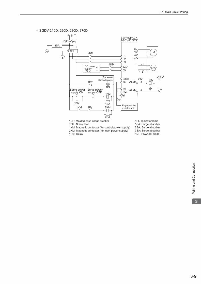
3.1 Main Circuit Wiring
3-9
3
Wirin
g a
nd
Co
nn
ectio
n
• SGDV-210D, 260D, 280D, 370D
ENC
SGDV-���D
UVW
M
0 V
1RyALM+
ALM−
3
4 1D
CN1
1QF
R S T
1FIL
+24 V
3SA
B2
12
B1/1Ry
1PL
1KM
2KM1SA
1Ry1KM
2SA
L12KM
L2L3
24VDC power supply (24 V)
+−
1KM
0V
1KMRegenerative resistor unit
(For servoalarm display)
supply ONServo power
supply OFFServo power
SERVOPACK
1QF: Molded-case circuit breaker1FIL: Noise filter1KM: Magnetic contactor (for control power supply)2KM: Magnetic contactor (for main power supply)1Ry: Relay
1PL: Indicator lamp1SA: Surge absorber2SA: Surge absorber3SA: Surge absorber1D: Flywheel diode
3 Wiring and Connection
3.1.4 General Precautions for Wiring
3-10
3.1.4 General Precautions for Wiring
To ensure safe, stable application of the servo system, observe the following precautions when wiring.
Use the connecting cables specified in the Σ-V Series Product Catalog (KAEP S800000 42). Design and arrange the system so that each cable will be as short as possible.
Observe the following precautions when wiring the main circuit.• Use shielded twisted-pair wires or shielded multi-core twisted-pair wires for signal lines and encoder lines.• The maximum wiring length is 3 m for signal lines and 50 m for encoder lines and main circuit lines.
Observe the following precautions when wiring the ground.
• Use a cable as thick as possible (at least 2.0 mm2).• Grounding to a resistance of 100 Ω or less for 100 V, 200 V SERVOPACKs, 10 Ω or less for 400 V SERVO-
PACKs is recommended.• Be sure to ground at only one point.• Ground the servomotor directly if the servomotor is insulated from the machine.
The signal cable conductors are as thin as 0.2 mm or 0.3 mm. Do not impose excessive bending force or tension.
Use a molded-case circuit breaker (1QF) or fuse to protect the main circuit.• The SERVOPACK connects directly to a commercial power supply; it is not isolated
through a transformer or other device.Always use a molded-case circuit breaker (1QF) or fuse to protect the servo system from accidents involving different power system voltages or other accidents.
Install a ground fault detector.• The SERVOPACK does not have a built-in protective circuit for grounding. To config-
ure a safer system, install a ground fault detector against overloads and short-circuit-ing, or install a ground fault detector combined with a molded-case circuit breaker.
Do not turn power ON and OFF frequently. • The power supply in the SERVOPACK contains a capacitor, which causes a high
charging current to flow when power is turned ON. Frequently turning power ON and OFF will causes the main circuit elements in the SERVOPACK to deteriorate.
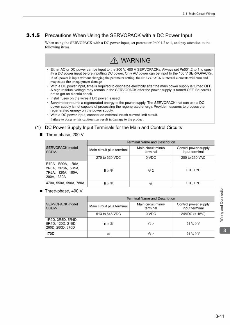
3.1 Main Circuit Wiring
3-11
3
Wirin
g a
nd
Co
nn
ectio
n
3.1.5 Precautions When Using the SERVOPACK with a DC Power InputWhen using the SERVOPACK with a DC power input, set parameter Pn001.2 to 1, and pay attention to the following items.
(1) DC Power Supply Input Terminals for the Main and Control Circuits Three-phase, 200 V
Three-phase, 400 V
WARNING• Either AC or DC power can be input to the 200 V, 400 V SERVOPACKs. Always set Pn001.2 to 1 to spec-
ify a DC power input before inputting DC power. Only AC power can be input to the 100 V SERVOPACKs.If DC power is input without changing the parameter setting, the SERVOPACK’s internal elements will burn and may cause fire or equipment damage.
• With a DC power input, time is required to discharge electricity after the main power supply is turned OFF. A high residual voltage may remain in the SERVOPACK after the power supply is turned OFF. Be careful not to get an electric shock.
• Install fuses on the wires if DC power is used.• Servomotor returns a regenerated energy to the power supply. The SERVOPACK that can use a DC
power supply is not capable of processing the regenerated energy. Provide measures to process the regenerated energy on the power supply.
• With a DC power input, connect an external inrush current limit circuit.Failure to observe this caution may result in damage to the product.
SERVOPACK modelSGDV-
Terminal Name and Description
Main circuit plus terminal Main circuit minus terminal
Control power supply input terminal
270 to 320 VDC 0 VDC 200 to 230 VAC
R70A,R90A, 1R6A,2R8A,3R8A, 5R5A,7R6A,120A, 180A,200A,330A
B1/ 2 L1C, L2C
470A, 550A, 590A, 780A B1/ L1C, L2C
SERVOPACK modelSGDV-
Terminal Name and Description
Main circuit plus terminal Main circuit minus terminal
Control power supply input terminal
513 to 648 VDC 0 VDC 24VDC (± 15%)
1R9D, 3R5D, 5R4D, 8R4D, 120D, 210D, 260D, 280D, 370D
B1/ 2 24 V, 0 V
170D 2 24 V, 0 V
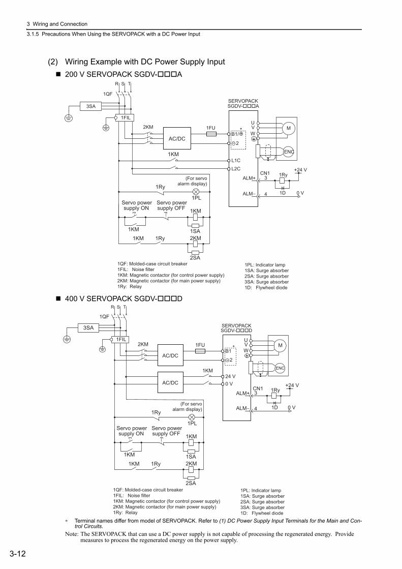
3 Wiring and Connection
3.1.5 Precautions When Using the SERVOPACK with a DC Power Input
3-12
(2) Wiring Example with DC Power Supply Input200 V SERVOPACK SGDV- A
400 V SERVOPACK SGDV- D
∗ Terminal names differ from model of SERVOPACK. Refer to (1) DC Power Supply Input Terminals for the Main and Con-trol Circuits.
Note: The SERVOPACK that can use a DC power supply is not capable of processing the regenerated energy. Provide measures to process the regenerated energy on the power supply.
1QF: Molded-case circuit breaker1FIL: Noise filter1KM: Magnetic contactor (for control power supply)2KM: Magnetic contactor (for main power supply)1Ry: Relay
1PL: Indicator lamp1SA: Surge absorber2SA: Surge absorber3SA: Surge absorber1D: Flywheel diode
1KM
1Ry
1PL
1KM
2KM1SA
1Ry1KM
2SA
L1C
L2C
B1/
SERVOPACKSGDV-���A
2
+*1FU2KM
ENC
UVW
M
0 V
1RyALM+
ALM−
3
4 1D
CN1+24 V
1KM
AC/DC
1QF
R S T
1FIL
3SA
(For servoalarm display)
supply ONServo power
supply OFFServo power
1QF: Molded-case circuit breaker1FIL: Noise filter1KM: Magnetic contactor (for control power supply)2KM: Magnetic contactor (for main power supply)1Ry: Relay
1PL: Indicator lamp1SA: Surge absorber2SA: Surge absorber3SA: Surge absorber1D: Flywheel diode
24 V0 V
B1
SERVOPACKSGDV-���D
2
1FU2KM
ENC
UVW
M
0 V
1RyALM+
ALM−
3
4 1D
CN1 +24 V
AC/DC
1QF
R S T
1FIL*
3SA
AC/DC
1KM
1Ry
1PL
1KM
2KM1SA
1Ry1KM
2SA
1KM
(For servoalarm display)
supply ONServo power
supply OFFServo power
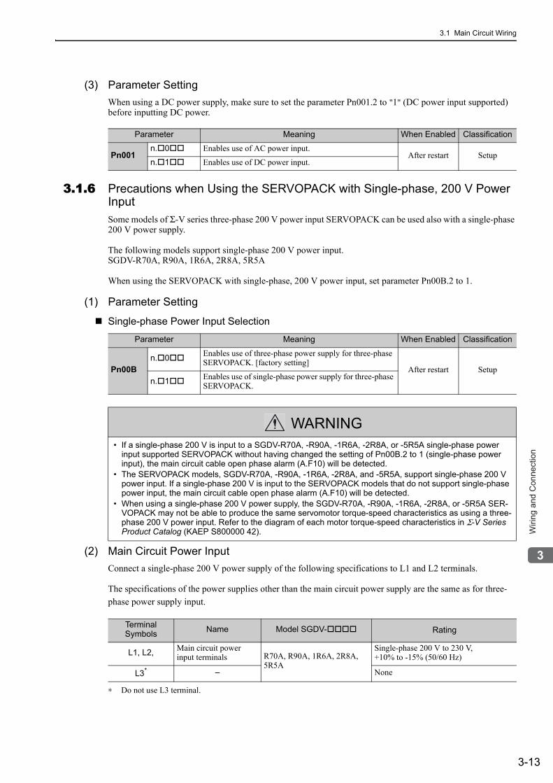
3.1 Main Circuit Wiring
3-13
3
Wirin
g a
nd
Co
nn
ectio
n
(3) Parameter SettingWhen using a DC power supply, make sure to set the parameter Pn001.2 to "1" (DC power input supported) before inputting DC power.
3.1.6 Precautions when Using the SERVOPACK with Single-phase, 200 V Power InputSome models of Σ-V series three-phase 200 V power input SERVOPACK can be used also with a single-phase 200 V power supply.
The following models support single-phase 200 V power input.SGDV-R70A, R90A, 1R6A, 2R8A, 5R5A
When using the SERVOPACK with single-phase, 200 V power input, set parameter Pn00B.2 to 1.
(1) Parameter Setting
Single-phase Power Input Selection
(2) Main Circuit Power InputConnect a single-phase 200 V power supply of the following specifications to L1 and L2 terminals.
The specifications of the power supplies other than the main circuit power supply are the same as for three-phase power supply input.
∗ Do not use L3 terminal.
Parameter Meaning When Enabled Classification
Pn001n. 0 Enables use of AC power input.
After restart Setupn. 1 Enables use of DC power input.
Parameter Meaning When Enabled Classification
Pn00Bn. 0 Enables use of three-phase power supply for three-phase
SERVOPACK. [factory setting]After restart Setup
n. 1 Enables use of single-phase power supply for three-phase SERVOPACK.
WARNING• If a single-phase 200 V is input to a SGDV-R70A, -R90A, -1R6A, -2R8A, or -5R5A single-phase power
input supported SERVOPACK without having changed the setting of Pn00B.2 to 1 (single-phase power input), the main circuit cable open phase alarm (A.F10) will be detected.
• The SERVOPACK models, SGDV-R70A, -R90A, -1R6A, -2R8A, and -5R5A, support single-phase 200 V power input. If a single-phase 200 V is input to the SERVOPACK models that do not support single-phase power input, the main circuit cable open phase alarm (A.F10) will be detected.
• When using a single-phase 200 V power supply, the SGDV-R70A, -R90A, -1R6A, -2R8A, or -5R5A SER-VOPACK may not be able to produce the same servomotor torque-speed characteristics as using a three-phase 200 V power input. Refer to the diagram of each motor torque-speed characteristics in Σ-V Series Product Catalog (KAEP S800000 42).
Terminal Symbols Name Model SGDV- Rating
L1, L2, Main circuit power input terminals R70A, R90A, 1R6A, 2R8A,
5R5A
Single-phase 200 V to 230 V, +10% to -15% (50/60 Hz)
L3* – None
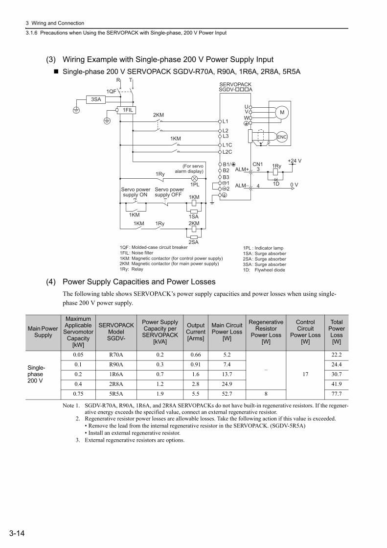
3 Wiring and Connection
3.1.6 Precautions when Using the SERVOPACK with Single-phase, 200 V Power Input
3-14
(3) Wiring Example with Single-phase 200 V Power Supply InputSingle-phase 200 V SERVOPACK SGDV-R70A, R90A, 1R6A, 2R8A, 5R5A
(4) Power Supply Capacities and Power LossesThe following table shows SERVOPACK’s power supply capacities and power losses when using single-phase 200 V power supply.
Note 1. SGDV-R70A, R90A, 1R6A, and 2R8A SERVOPACKs do not have built-in regenerative resistors. If the regener-ative energy exceeds the specified value, connect an external regenerative resistor.
2. Regenerative resistor power losses are allowable losses. Take the following action if this value is exceeded.• Remove the lead from the internal regenerative resistor in the SERVOPACK. (SGDV-5R5A)• Install an external regenerative resistor.
3. External regenerative resistors are options.
1PL1SA2SA3SA1D:
: Indicator lamp: Surge absorber: Surge absorber: Surge absorber Flywheel diode
1QF1FIL1KM
: Molded-case circuit breaker: Noise filter: Magnetic contactor (for control power supply)
2KM: Magnetic contactor (for main power supply)1Ry: Relay
1KM
1Ry
1PL
1KM
2KM1SA
1Ry1KM
2SA
L1
ENC
SERVOPACKSGDV-���A
UVW
M
0 V
1RyALM+
ALM−
3
4 1D
2KM
L3
B2B3
L2
CN1
1QF
R T
1FIL
+24 V
12
L1C1KM
L2C
3SA
B1/(For servoalarm display)
supply ONServo power
supply OFFServo power
Main Power Supply
Maximum Applicable Servomotor
Capacity[kW]
SERVOPACK ModelSGDV-
Power Supply Capacity per SERVOPACK
[kVA]
Output Current[Arms]
Main Circuit Power Loss
[W]
Regenerative Resistor
Power Loss [W]
Control Circuit
Power Loss [W]
Total Power Loss [W]
Single-phase 200 V
0.05 R70A 0.2 0.66 5.2
–17
22.2
0.1 R90A 0.3 0.91 7.4 24.4
0.2 1R6A 0.7 1.6 13.7 30.7
0.4 2R8A 1.2 2.8 24.9 41.9
0.75 5R5A 1.9 5.5 52.7 8 77.7
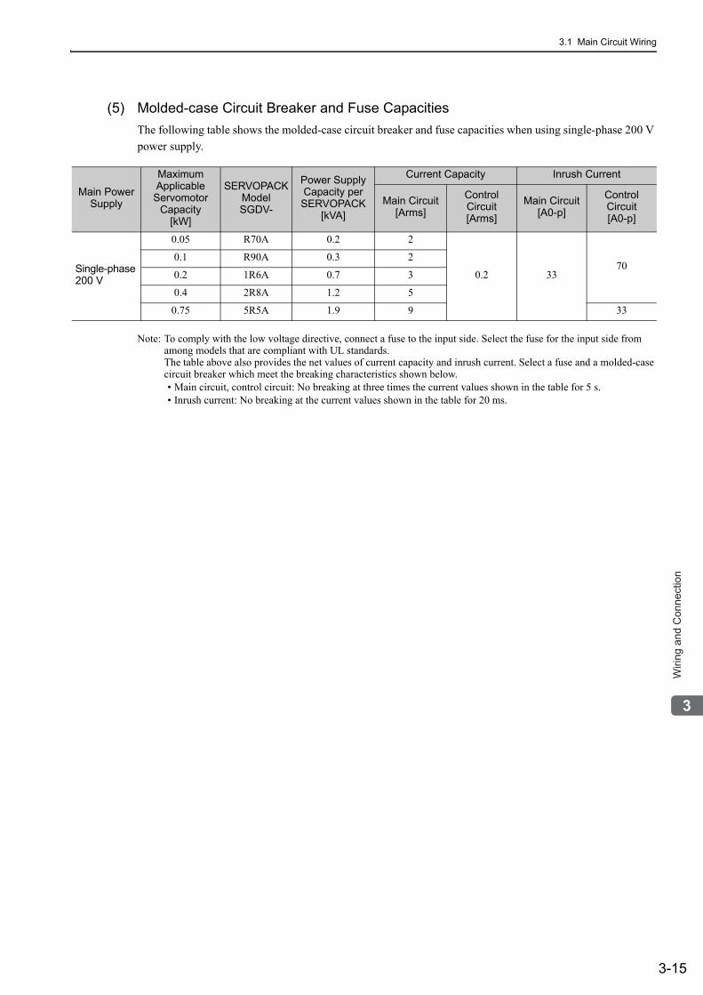
3.1 Main Circuit Wiring
3-15
3
Wirin
g a
nd
Co
nn
ectio
n
(5) Molded-case Circuit Breaker and Fuse CapacitiesThe following table shows the molded-case circuit breaker and fuse capacities when using single-phase 200 V power supply.
Note: To comply with the low voltage directive, connect a fuse to the input side. Select the fuse for the input side from among models that are compliant with UL standards.The table above also provides the net values of current capacity and inrush current. Select a fuse and a molded-case circuit breaker which meet the breaking characteristics shown below.• Main circuit, control circuit: No breaking at three times the current values shown in the table for 5 s.• Inrush current: No breaking at the current values shown in the table for 20 ms.
Main Power Supply
Maximum Applicable
Servomotor Capacity
[kW]
SERVOPACK ModelSGDV-
Power Supply Capacity per SERVOPACK
[kVA]
Current Capacity Inrush Current
Main Circuit[Arms]
Control Circuit[Arms]
Main Circuit[A0-p]
Control Circuit[A0-p]
Single-phase 200 V
0.05 R70A 0.2 2
0.2 3370
0.1 R90A 0.3 2
0.2 1R6A 0.7 3
0.4 2R8A 1.2 5
0.75 5R5A 1.9 9 33
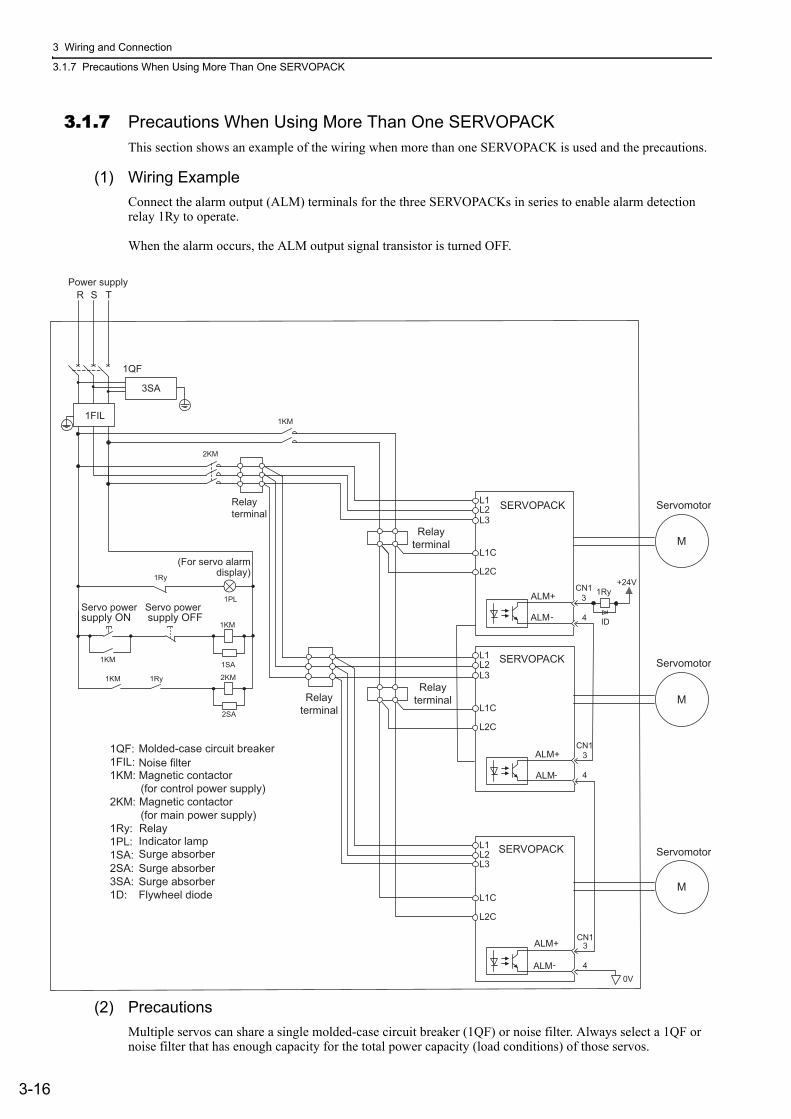
3 Wiring and Connection
3.1.7 Precautions When Using More Than One SERVOPACK
3-16
3.1.7 Precautions When Using More Than One SERVOPACKThis section shows an example of the wiring when more than one SERVOPACK is used and the precautions.
(1) Wiring ExampleConnect the alarm output (ALM) terminals for the three SERVOPACKs in series to enable alarm detection relay 1Ry to operate.
When the alarm occurs, the ALM output signal transistor is turned OFF.
(2) PrecautionsMultiple servos can share a single molded-case circuit breaker (1QF) or noise filter. Always select a 1QF or noise filter that has enough capacity for the total power capacity (load conditions) of those servos.
L1L2L3
L1C
L2C
SERVOPACK
Servomotor
Servomotor
M
Servomotor
M
M
Relayterminal
Relayterminal
Relayterminal
1QF: 1FIL: 1KM: Magnetic contactor (for control power supply) 2KM: (for main power supply) 1Ry: 1PL: 1SA: 2SA:3SA:1D:
Molded-case circuit breakerNoise filter
Relay
Magnetic contactor
Indicator lampSurge absorber
1Ry+24VCN1
CN1
CN1
3ALM+
4ALM -
0V
L1L2L3
3ALM+
4ALM -
L1L2L3
L1C
ID
3ALM+
4ALM -
L2C
L1C
L2C
SERVOPACK
SERVOPACK
Surge absorberSurge absorberFlywheel diode
supply ON
1KM
R S T
1QF
2KM
Power supply
1FIL
Relayterminal
3SA
1KM
(For servo alarmdisplay)1Ry
1PL
1KM
2KM
1SA
Servo powersupply OFFServo power
1Ry1KM
2SA
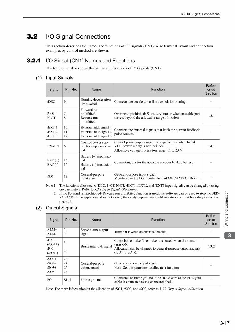
3.2 I/O Signal Connections
3-17
3
Wirin
g a
nd
Co
nn
ectio
n
3.2 I/O Signal ConnectionsThis section describes the names and functions of I/O signals (CN1). Also terminal layout and connection examples by control method are shown.
3.2.1 I/O Signal (CN1) Names and FunctionsThe following table shows the names and functions of I/O signals (CN1).
(1) Input Signals
Note 1. The functions allocated to /DEC, P-OT, N-OT, /EXT1, /EXT2, and /EXT3 input signals can be changed by using the parameters. Refer to 3.3.1 Input Signal Allocations.
2. If the Forward run prohibited/ Reverse run prohibited function is used, the software can be used to stop the SER-VOPACK. If the application does not satisfy the safety requirements, add an external circuit for safety reasons as required.
(2) Output Signals
Note: For more information on the allocation of /SO1, /SO2, and /SO3, refer to 3.3.2 Output Signal Allocation.
Signal Pin No. Name FunctionRefer-ence
Section
/DEC 9 Homing decelerationlimit switch Connects the deceleration limit switch for homing. −
P-OTN-OT
78
Forward run prohibited,Reverse run prohibited
Overtravel prohibited: Stops servomotor when movable part travels beyond the allowable range of motion. 4.3.1
/EXT 1/EXT 2/EXT 3
101112
External latch signal 1External latch signal 2External latch signal 3
Connects the external signals that latch the current feedback pulse counter. −
+24VIN 6Control power sup-ply for sequence sig-nal
Control power supply input for sequence signals: The 24 VDC power supply is not included.Allowable voltage fluctuation range: 11 to 25 V
3.4.1
BAT (+)BAT (-)
1415
Battery (+) input sig-nalBattery (−) input sig-nal
Connecting pin for the absolute encoder backup battery. −
/SI0 13 General-purpose input signal
General-purpose input signal:Monitored in the I/O monitor field of MECHATROLINK-II. −
Signal Pin No. Name FunctionRefer-ence
Section
ALM+ALM-
34
Servo alarm output signal Turns OFF when an error is detected. −
/BK+(/SO1+)/BK-(/SO1-)
1
2Brake interlock signal
Controls the brake. The brake is released when the signal turns ON.Allocation can be changed to general-purpose output signals (/SO1+, /SO1-).
4.3.2
/SO2+/SO2-/SO3+/SO3-
23242526
General-purposeoutput signal
General-purpose output signalNote: Set the parameter to allocate a function. −
FG Shell Frame ground Connected to frame ground if the shield wire of the I/O signal cable is connected to the connector shell. −
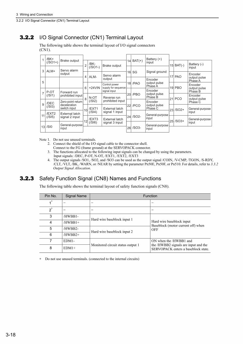
3 Wiring and Connection
3.2.2 I/O Signal Connector (CN1) Terminal Layout
3-18
3.2.2 I/O Signal Connector (CN1) Terminal LayoutThe following table shows the terminal layout of I/O signal connectors (CN1).
Note 1. Do not use unused terminals.2. Connect the shield of the I/O signal cable to the connector shell.
Connect to the FG (frame ground) at the SERVOPACK connector.3. The functions allocated to the following input signals can be changed by using the parameters.
Input signals: /DEC, P-OT, N-OT, /EXT1, /EXT2, /EXT34. The output signals /SO1, /SO2, and /SO3 can be used as the output signal /COIN, /V-CMP, /TGON, /S-RDY,
/CLT, /VLT, /BK, /WARN, or /NEAR by setting the parameter Pn50E, Pn50F, or Pn510. For details, refer to 3.3.2 Output Signal Allocation.
3.2.3 Safety Function Signal (CN8) Names and FunctionsThe following table shows the terminal layout of safety function signals (CN8).
∗ Do not use unused terminals. (connected to the internal circuits)
1
3
5
7
9
11
13
2
4
6
8
10
12
14
16
18
20
22
24
26
15
17
19
21
23
25
/BK+(/SO1+) Brake output
Servo alarmoutput
Forward runprohibited input
External latchsignal 2 input
External latchsignal 1 input
External latchsignal 3 input
General-purposeinput
General-purposeinput
General-purposeinput
General-purposeinput
General-purposeinput
Zero-point returndecelerationswitch input
Reverse runprohibited input
Servo alarmoutput
Control powersupply for sequence signal input
Brake output
Battery (+) input Battery (-)
inputSignal ground
Encoderoutput pulsePhase A
Encoderoutput pulsePhase AEncoderoutput pulsePhase BEncoderoutput pulsePhase C
Encoderoutput pulsePhase BEncoderoutput pulsePhase C
P-OT(/SI1)
/DEC(/SI3)
/EXT2(/SI5)
/SI0
ALM+
/BK-(/SO1-)
N-OT(/SI2)
/EXT1(/SI4)
/EXT3(/SI6)
ALM-
+24VIN
BAT(+)
SG
/PAO
/PBO
/PCO
/SO2-
/SO3-
BAT(-)
PAO
PBO
PCO
/SO2+
/SO3+
Pin No. Signal Name Function
1* − − −
2* − − −
3 /HWBB1-Hard wire baseblock input 1 Hard wire baseblock input
Baseblock (motor current off) when OFF
4 /HWBB1+
5 /HWBB2-Hard wire baseblock input 2
6 /HWBB2+
7 EDM1-Monitored circuit status output 1
ON when the /HWBB1 and the /HWBB2 signals are input and the SERVOPACK enters a baseblock state.8 EDM1+
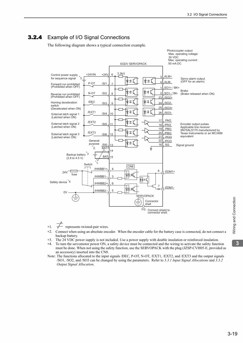
3.2 I/O Signal Connections
3-19
3
Wirin
g a
nd
Co
nn
ectio
n
3.2.4 Example of I/O Signal ConnectionsThe following diagram shows a typical connection example.
∗1. represents twisted-pair wires.∗2. Connect when using an absolute encoder. When the encoder cable for the battery case is connected, do not connect a
backup battery.∗3. The 24 VDC power supply is not included. Use a power supply with double insulation or reinforced insulation.∗4. To turn the servomotor power ON, a safety device must be connected and the wiring to activate the safety function
must be done. When not using the safety function, use the SERVOPACK with the plug (JZSP-CVH05-E, provided as an accessory) inserted into the CN8.
Note: The functions allocated to the input signals /DEC, P-OT, N-OT, /EXT1, /EXT2, and /EXT3 and the output signals /SO1, /SO2, and /SO3 can be changed by using the parameters. Refer to 3.3.1 Input Signal Allocations and 3.3.2 Output Signal Allocation.
*3Backup battery(2.8 to 4.5 V)
Reverse run prohibited(Prohibited when OFF)
Forward run prohibited(Prohibited when OFF)
Servo alarm output(OFF for an alarm)
Photocoupler outputMax. operating voltage:30 VDCMax. operating current: 50 mA DC
Connect shield to connector shell.
Connectorshell
SERVOPACK
Switch
fuse
Safety device *4
SO1+ / BK+
SO1- / BK-/SO2+
/SO2-
/SO3+
ALM+
ALM-
1
223
24
3
4
+24VIN +24V 3.3kΩ
/SI1
/SI2
/SI3
/SI4
/SI5
6
8
10
9
11
12/SI6
/SI0
P-OT
N-OT
/DEC
/EXT1
/EXT2
/EXT3
General-purpose
BAT+
BAT-
13
14
15
7
/SO3-External latch signal 1(Latched when ON)
External latch signal 2(Latched when ON)
External latch signal 3(Latched when ON)
Homing decelerationswitch(Decelerated when ON)
Brake (Brake released when ON)
Encoder output pulses Applicable line receiver SN75ALS175 manufactured by Texas Instruments or an MC3486 equivalent
Signal ground
SGDV SERVOPACK
PBO
PCO/PBO
PAO/PAO
/PCO
19
25
26
1718
20212216 SG
*1.
*2.
*3.
EDM1+
EDM1-
FG
/HWBB1+
/HWBB1-
/HWBB2+
/HWBB2-
24V
0V
CN8
6
3
4
5
8
7
Control power supply for sequence signal
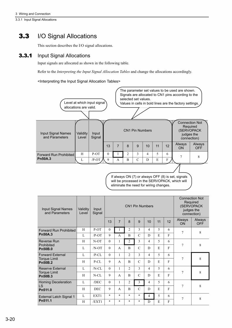
3 Wiring and Connection
3.3.1 Input Signal Allocations
3-20
3.3 I/O Signal AllocationsThis section describes the I/O signal allocations.
3.3.1 Input Signal AllocationsInput signals are allocated as shown in the following table.
Refer to the Interpreting the Input Signal Allocation Tables and change the allocations accordingly.
<Interpreting the Input Signal Allocation Tables>
Input Signal Names and Parameters
Validity Level
Input Signal
CN1 Pin Numbers
Connection Not Required
(SERVOPACK judges the connection)
13 7 8 9 10 11 12 Always ON
Always OFF
Forward Run ProhibitedPn50A.3
H P-OT 0 1 2 3 4 5 67 8
L /P-OT 9 A B C D E F
Level at which input signalallocations are valid.
The parameter set values to be used are shown. Signals are allocated to CN1 pins according to the selected set values. Values in cells in bold lines are the factory settings.
If always ON (7) or always OFF (8) is set, signals will be processed in the SERVOPACK, which will eliminate the need for wiring changes.
Input Signal Names and Parameters
Validity Level
Input Signal
CN1 Pin Numbers
Connection Not Required
(SERVOPACK judges the connection)
13 7 8 9 10 11 12 Always ON
Always OFF
Forward Run ProhibitedPn50A.3
H P-OT 0 1 2 3 4 5 67 8
L /P-OT 9 A B C D E F
Reverse Run ProhibitedPn50B.0
H N-OT 0 1 2 3 4 5 67 8
L /N-OT 0 A B C D E F
Forward External Torque LimitPn50B.2
L /P-CL 0 1 2 3 4 5 67 8
H P-CL 9 A B C D E F
Reserve External Torque LimitPn50B.3
L /N-CL 0 1 2 3 4 5 67 8
H N-CL 9 A B C D E F
Homing Deceleration LS Pn511.0
L /DEC 0 1 2 3 4 5 67 8
H DEC 9 A B C D E F
External Latch Signal 1Pn511.1
L EXT1 * * * * 4 5 67 8
H /EXT1 * * * * D E F
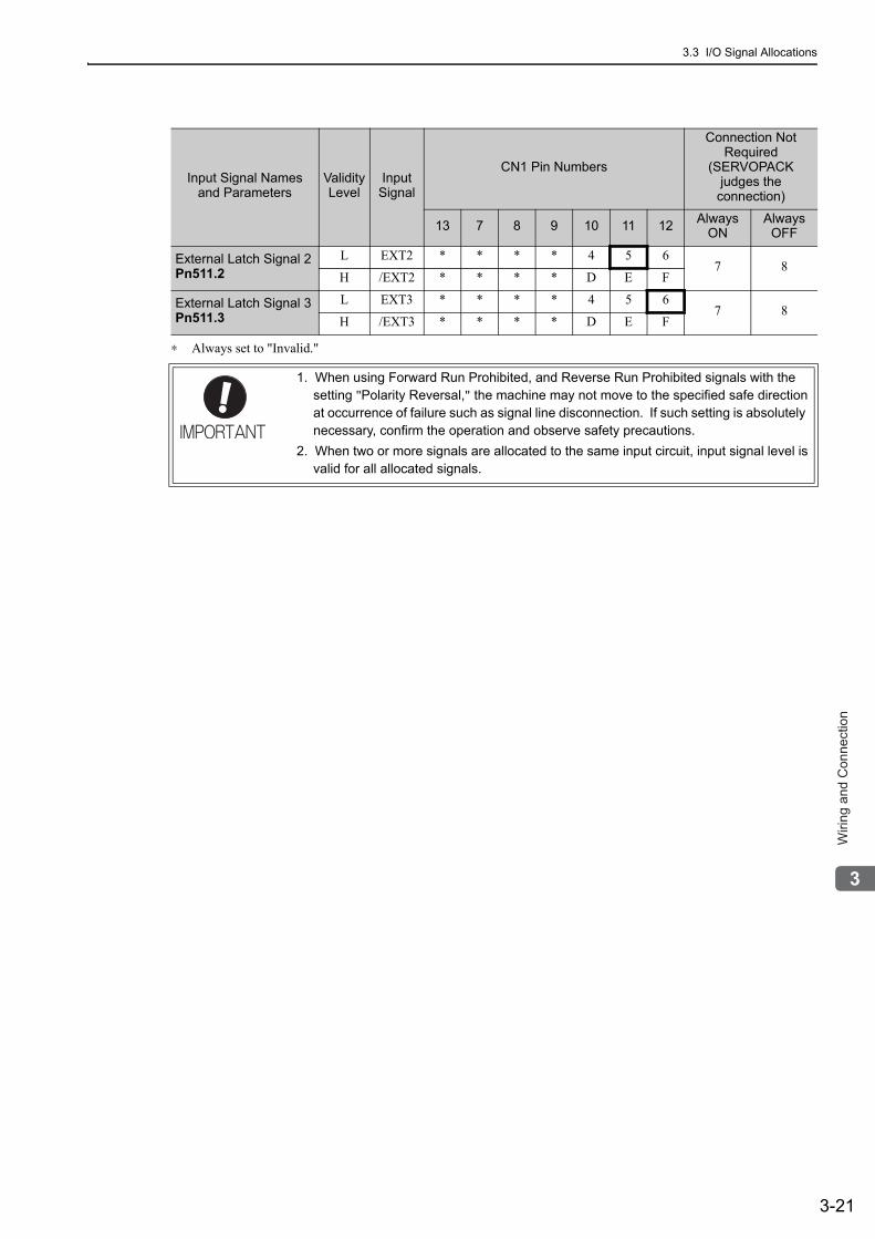
3.3 I/O Signal Allocations
3-21
3
Wirin
g a
nd
Co
nn
ectio
n
∗ Always set to "Invalid."
External Latch Signal 2Pn511.2
L EXT2 * * * * 4 5 67 8
H /EXT2 * * * * D E F
External Latch Signal 3Pn511.3
L EXT3 * * * * 4 5 67 8
H /EXT3 * * * * D E F
Input Signal Names and Parameters
Validity Level
Input Signal
CN1 Pin Numbers
Connection Not Required
(SERVOPACK judges the
connection)
13 7 8 9 10 11 12 Always ON
Always OFF
1. When using Forward Run Prohibited, and Reverse Run Prohibited signals with the setting "Polarity Reversal," the machine may not move to the specified safe direction at occurrence of failure such as signal line disconnection. If such setting is absolutely necessary, confirm the operation and observe safety precautions.
2. When two or more signals are allocated to the same input circuit, input signal level is valid for all allocated signals.
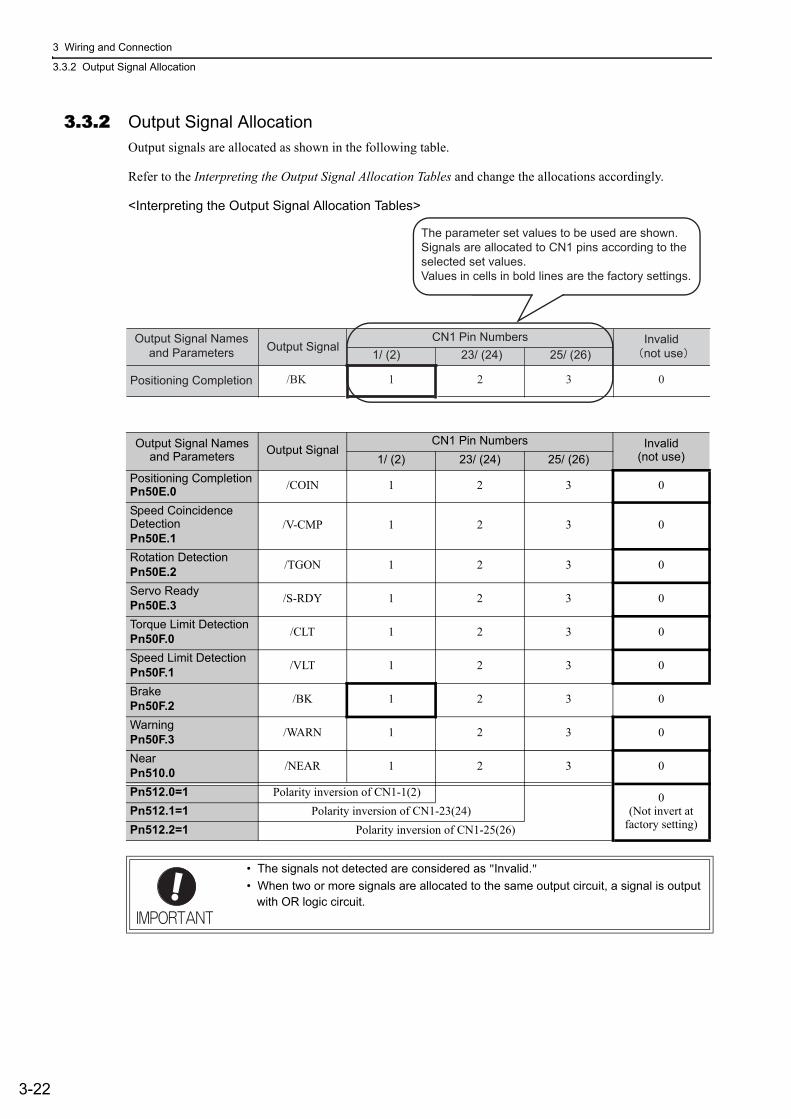
3 Wiring and Connection
3.3.2 Output Signal Allocation
3-22
3.3.2 Output Signal AllocationOutput signals are allocated as shown in the following table.
Refer to the Interpreting the Output Signal Allocation Tables and change the allocations accordingly.
<Interpreting the Output Signal Allocation Tables>
Output Signal Names and Parameters Output Signal
CN1 Pin Numbers Invalid(not use)1/ (2) 23/ (24) 25/ (26)
Positioning CompletionPn50E.0 /COIN 1 2 3 0
Speed Coincidence DetectionPn50E.1
/V-CMP 1 2 3 0
Rotation DetectionPn50E.2 /TGON 1 2 3 0
Servo ReadyPn50E.3 /S-RDY 1 2 3 0
Torque Limit DetectionPn50F.0 /CLT 1 2 3 0
Speed Limit DetectionPn50F.1 /VLT 1 2 3 0
BrakePn50F.2 /BK 1 2 3 0
WarningPn50F.3 /WARN 1 2 3 0
NearPn510.0 /NEAR 1 2 3 0
Pn512.0=1 Polarity inversion of CN1-1(2) 0(Not invert at
factory setting)Pn512.1=1 Polarity inversion of CN1-23(24)Pn512.2=1 Polarity inversion of CN1-25(26)
• The signals not detected are considered as "Invalid." • When two or more signals are allocated to the same output circuit, a signal is output
with OR logic circuit.
Output SignalCN1 Pin Numbers Invalid
not use1/ (2) 23/ (24) 25/ (26)
Positioning Completion /BK 1 2 3 0
The parameter set values to be used are shown. Signals are allocated to CN1 pins according to the selected set values. Values in cells in bold lines are the factory settings.
Output Signal Names and Parameters
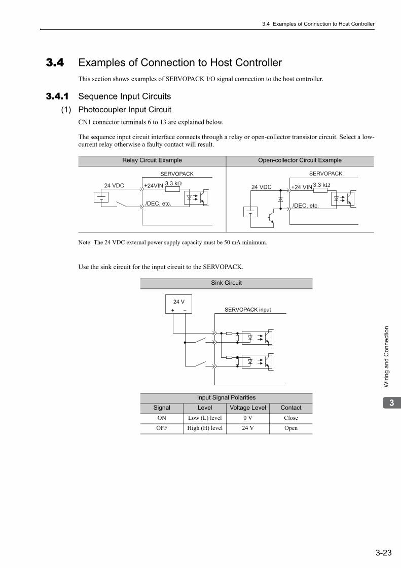
3.4 Examples of Connection to Host Controller
3-23
3
Wirin
g a
nd
Co
nn
ectio
n
3.4 Examples of Connection to Host ControllerThis section shows examples of SERVOPACK I/O signal connection to the host controller.
3.4.1 Sequence Input Circuits(1) Photocoupler Input Circuit
CN1 connector terminals 6 to 13 are explained below.
The sequence input circuit interface connects through a relay or open-collector transistor circuit. Select a low-current relay otherwise a faulty contact will result.
Note: The 24 VDC external power supply capacity must be 50 mA minimum.
Use the sink circuit for the input circuit to the SERVOPACK.
Relay Circuit Example Open-collector Circuit Example
Sink Circuit
Input Signal Polarities
Signal Level Voltage Level Contact
ON Low (L) level 0 V Close
OFF High (H) level 24 V Open
3.3 kΩ
/DEC, etc.
SERVOPACK
24 VDC +24VIN +24 VIN3.3 kΩ
/DEC, etc.
SERVOPACK
24 VDC
SERVOPACK input24 V
+ −
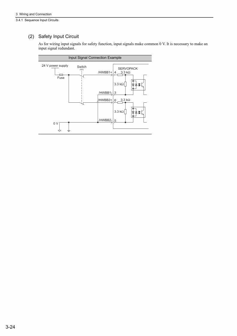
3 Wiring and Connection
3.4.1 Sequence Input Circuits
3-24
(2) Safety Input CircuitAs for wiring input signals for safety function, input signals make common 0 V. It is necessary to make an input signal redundant.
Input Signal Connection Example
24 V power supply
0 V
Switch
Fuse
/HWBB1+ 4 3.3 kΩ
3.3 kΩ
3.3 kΩ
3.3 kΩ
3
6
5
SERVOPACK
/HWBB1-
/HWBB2+
/HWBB2-
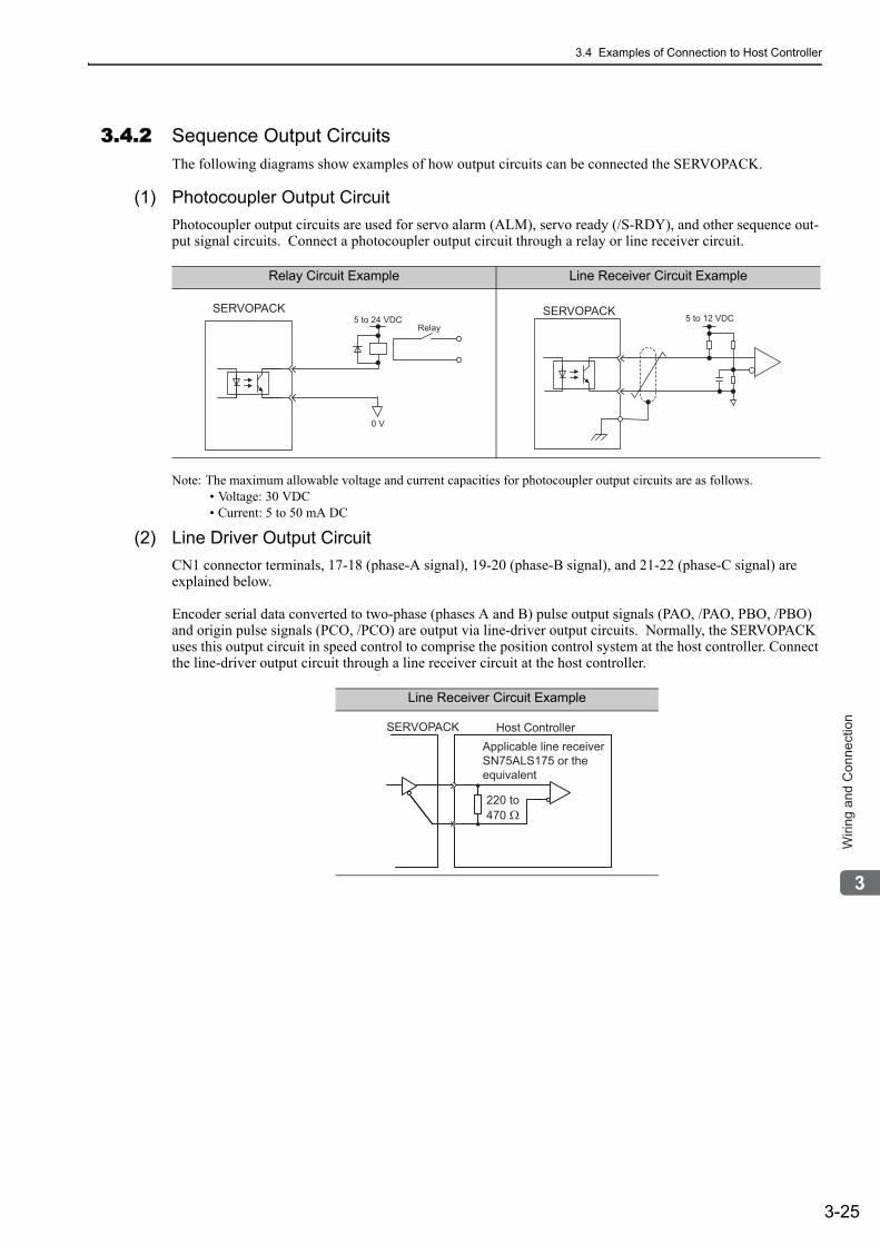
3.4 Examples of Connection to Host Controller
3-25
3
Wirin
g a
nd
Co
nn
ectio
n
3.4.2 Sequence Output CircuitsThe following diagrams show examples of how output circuits can be connected the SERVOPACK.
(1) Photocoupler Output CircuitPhotocoupler output circuits are used for servo alarm (ALM), servo ready (/S-RDY), and other sequence out-put signal circuits. Connect a photocoupler output circuit through a relay or line receiver circuit.
Note: The maximum allowable voltage and current capacities for photocoupler output circuits are as follows.• Voltage: 30 VDC• Current: 5 to 50 mA DC
(2) Line Driver Output CircuitCN1 connector terminals, 17-18 (phase-A signal), 19-20 (phase-B signal), and 21-22 (phase-C signal) are explained below.
Encoder serial data converted to two-phase (phases A and B) pulse output signals (PAO, /PAO, PBO, /PBO) and origin pulse signals (PCO, /PCO) are output via line-driver output circuits. Normally, the SERVOPACK uses this output circuit in speed control to comprise the position control system at the host controller. Connect the line-driver output circuit through a line receiver circuit at the host controller.
Relay Circuit Example Line Receiver Circuit Example
0 V
Relay5 to 24 VDC
SERVOPACK SERVOPACK5 to 12 VDC
Line Receiver Circuit Example
Applicable line receiver SN75ALS175 or the equivalent
Host Controller
220 to470 Ω
SERVOPACK
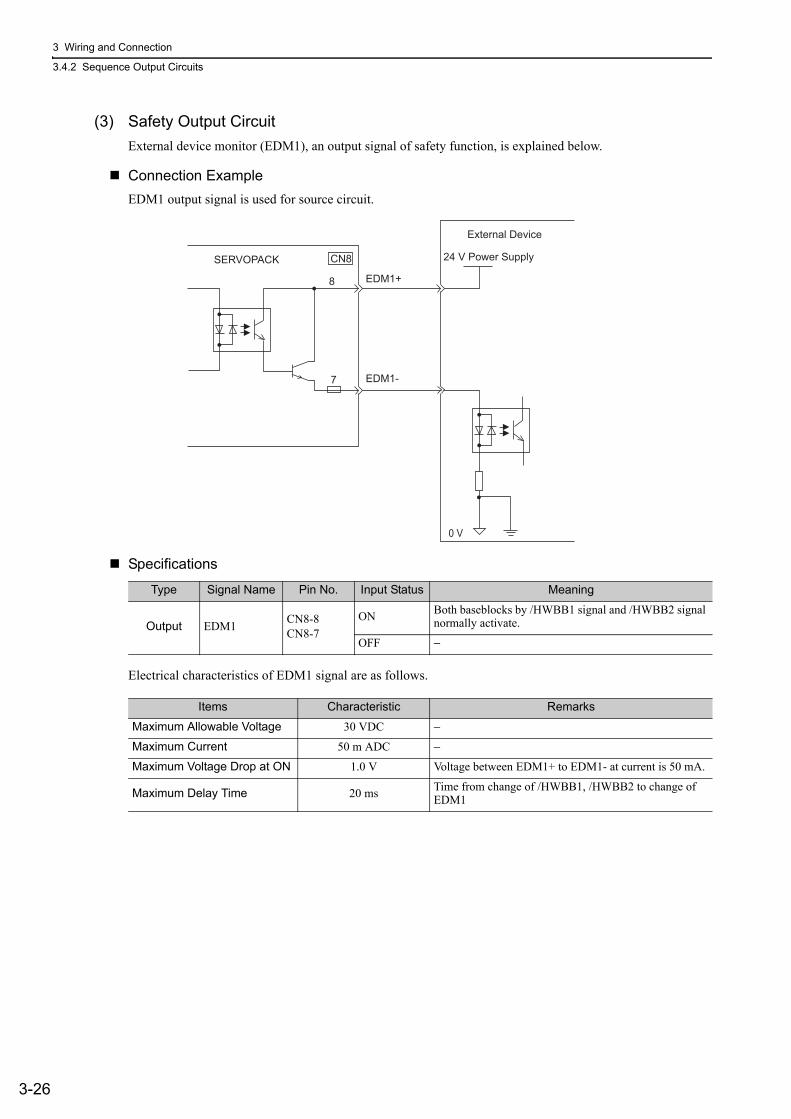
3 Wiring and Connection
3.4.2 Sequence Output Circuits
3-26
(3) Safety Output CircuitExternal device monitor (EDM1), an output signal of safety function, is explained below.
Connection ExampleEDM1 output signal is used for source circuit.
Specifications
Electrical characteristics of EDM1 signal are as follows.
24 V Power SupplySERVOPACK
External Device
EDM1+
EDM1-
0 V
8
7
CN8
Type Signal Name Pin No. Input Status Meaning
Output EDM1 CN8-8CN8-7
ON Both baseblocks by /HWBB1 signal and /HWBB2 signal normally activate.
OFF −
Items Characteristic Remarks
Maximum Allowable Voltage 30 VDC −
Maximum Current 50 m ADC −
Maximum Voltage Drop at ON 1.0 V Voltage between EDM1+ to EDM1- at current is 50 mA.
Maximum Delay Time 20 ms Time from change of /HWBB1, /HWBB2 to change of EDM1
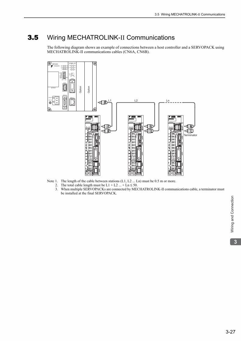
3.5 Wiring MECHATROLINK-II Communications
3-27
3
Wirin
g a
nd
Co
nn
ectio
n
3.5 Wiring MECHATROLINK-II CommunicationsThe following diagram shows an example of connections between a host controller and a SERVOPACK using MECHATROLINK-II communications cables (CN6A, CN6B).
Note 1. The length of the cable between stations (L1, L2 ... Ln) must be 0.5 m or more.2. The total cable length must be L1 + L2 ... + Ln ≤ 50.3. When multiple SERVOPACKs are connected by MECHATROLINK-II communications cable, a terminator must
be installed at the final SERVOPACK.
LnL1 L2
Terminator
DC24V
DC 0V
MP2300
YASKAWA
TEST
Option
Option
RDY
ALM
TX
RUN
ERR
BAT
MON
CNFGINT
SUP
STOP
SW1
OFF ON
BATTERY
CPU I/O
M-I/II
218IF-01
ERR
COL
RX
RUN
STRX
TX
INIT
TEST
ONOFF
PORT
10Base-T
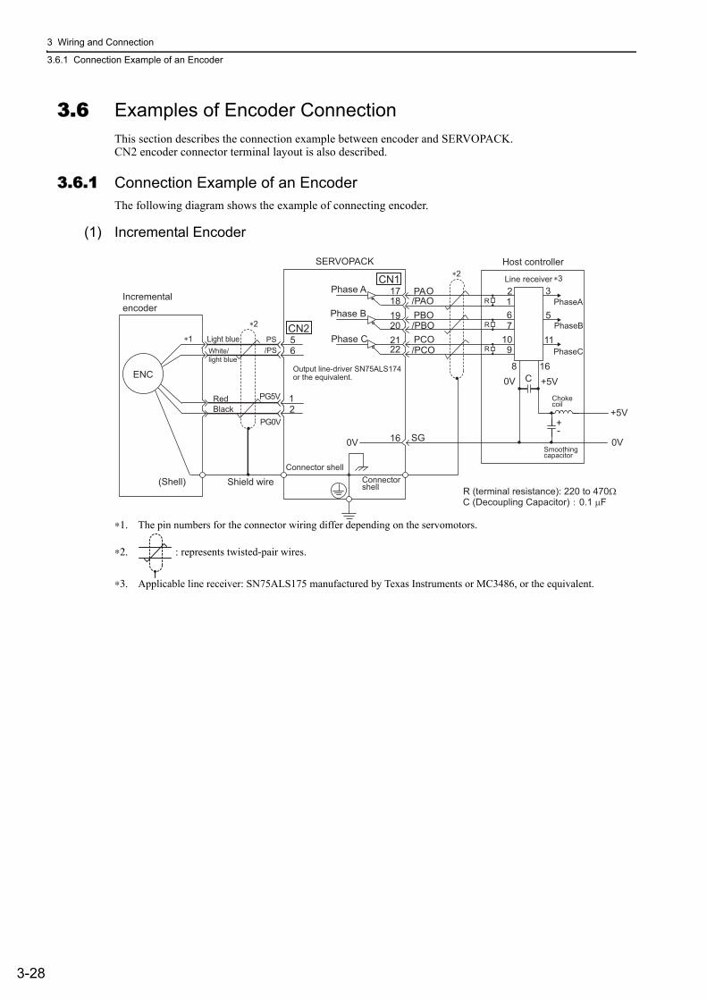
3 Wiring and Connection
3.6.1 Connection Example of an Encoder
3-28
3.6 Examples of Encoder ConnectionThis section describes the connection example between encoder and SERVOPACK.CN2 encoder connector terminal layout is also described.
3.6.1 Connection Example of an EncoderThe following diagram shows the example of connecting encoder.
(1) Incremental Encoder
∗1. The pin numbers for the connector wiring differ depending on the servomotors.
∗2. : represents twisted-pair wires.
∗3. Applicable line receiver: SN75ALS175 manufactured by Texas Instruments or MC3486, or the equivalent.
19
0V SG16
0V
0V
+5V
+5V
PAO/PAOPBO/PBOPCO/PCO
12
56
CN2
1718
202122
CN1
Light blue
PG5V
PG0V
PS/PSWhite/
light blue
Incrementalencoder
RedBlack
Shield wire(Shell)Connector shell
Connector shell
Output line-driver SN75ALS174 or the equivalent.
Phase APhaseA
Phase BPhaseB
Phase CPhaseC
SERVOPACK
Line receiver
Host controller
Chokecoil
Smoothingcapacitor
R (terminal resistance): 220 to 470ΩC (Decoupling Capacitor) 0.1 μF
11
5
321R
R
R
67
109
8 16C
+-
∗1
∗2
∗2 ∗3
ENC
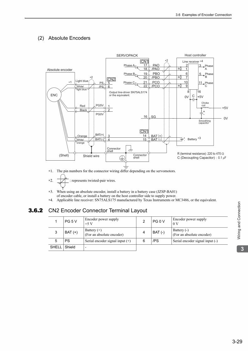
3.6 Examples of Encoder Connection
3-29
3
Wirin
g a
nd
Co
nn
ectio
n
(2) Absolute Encoders
∗1. The pin numbers for the connector wiring differ depending on the servomotors.
∗2. : represents twisted-pair wires.
∗3. When using an absolute encoder, install a battery in a battery case (JZSP-BA01)of encoder cable, or install a battery on the host controller side to supply power.
∗4. Applicable line receiver: SN75ALS175 manufactured by Texas Instruments or MC3486, or the equivalent.
3.6.2 CN2 Encoder Connector Terminal Layout
/PCO
34
1415
BATBAT
+-
CN2
171819202122
CN1
SG16
PAO/PAOPBO
/PBOPCOLight blue
White/light blue
Absolute encoder
RedBlack
Shield wire
OrangeWhite/orange
(Shell)
SERVOPACK
Phase A
Phase B
Phase C
Connectorshell
Connectorshell
CN1
∗2 ∗4
∗3
∗2
∗1
0V
0V
+5V
+5V
PhaseA
Phase B
PhaseC
Line receiver
Host controller
Chokecoil
Smoothingcapacitor
R (terminal resistance): 220 to 470 ΩC (Decoupling Capacitor) 0.1 μF
11
5
321R
67
109
8 16C
+-
R
R
+- Battery
56
12
Output line-driver SN75ALS174 or the equivalent.
PS/PS
PG5V
PG0V
BAT(+)BAT(-)
ENC
1 PG 5 V Encoder power supply+5 V 2 PG 0 V Encoder power supply
0 V
3 BAT (+) Battery (+)(For an absolute encoder) 4 BAT (-) Battery (-)
(For an absolute encoder)
5 PS Serial encoder signal input (+) 6 /PS Serial encoder signal input (-)
SHELL Shield -
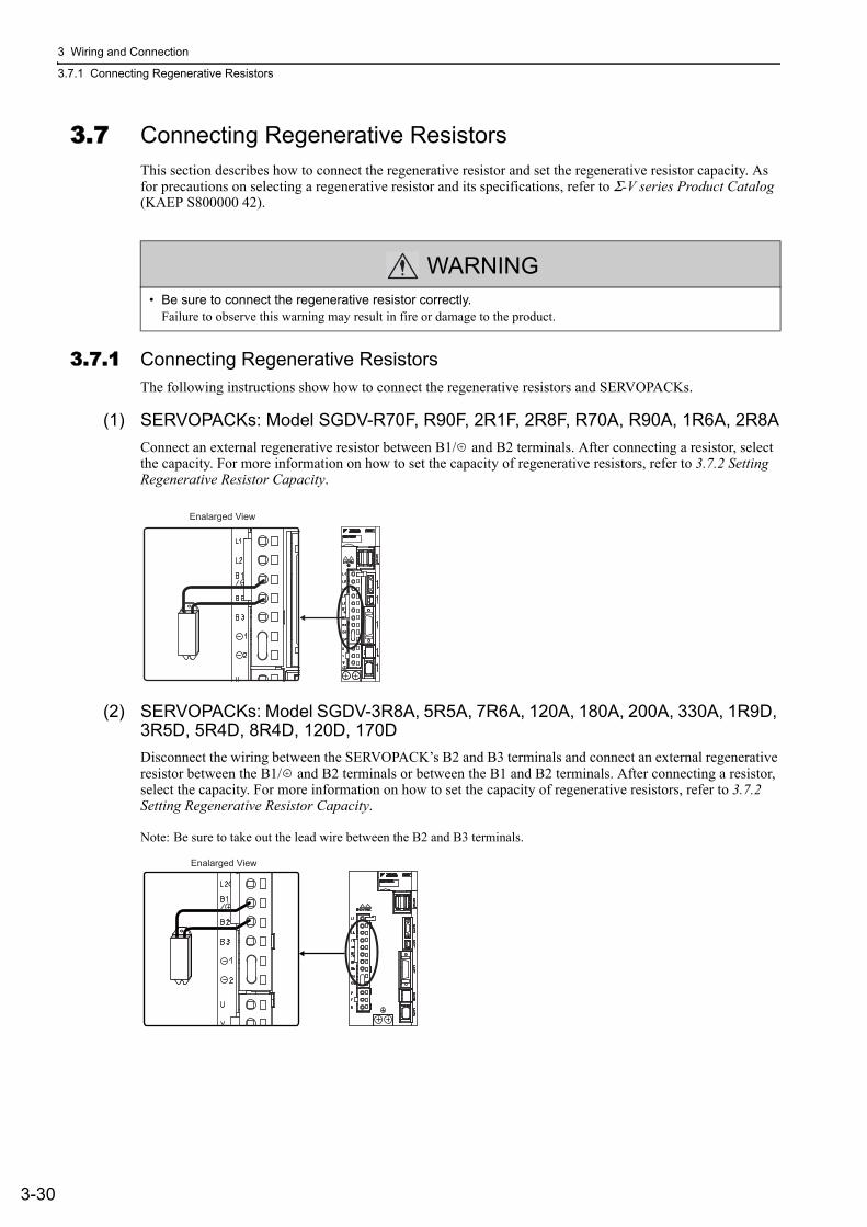
3 Wiring and Connection
3.7.1 Connecting Regenerative Resistors
3-30
3.7 Connecting Regenerative ResistorsThis section describes how to connect the regenerative resistor and set the regenerative resistor capacity. As for precautions on selecting a regenerative resistor and its specifications, refer to Σ-V series Product Catalog (KAEP S800000 42).
3.7.1 Connecting Regenerative ResistorsThe following instructions show how to connect the regenerative resistors and SERVOPACKs.
(1) SERVOPACKs: Model SGDV-R70F, R90F, 2R1F, 2R8F, R70A, R90A, 1R6A, 2R8AConnect an external regenerative resistor between B1/ and B2 terminals. After connecting a resistor, select the capacity. For more information on how to set the capacity of regenerative resistors, refer to 3.7.2 Setting Regenerative Resistor Capacity.
(2) SERVOPACKs: Model SGDV-3R8A, 5R5A, 7R6A, 120A, 180A, 200A, 330A, 1R9D, 3R5D, 5R4D, 8R4D, 120D, 170DDisconnect the wiring between the SERVOPACK’s B2 and B3 terminals and connect an external regenerative resistor between the B1/ and B2 terminals or between the B1 and B2 terminals. After connecting a resistor, select the capacity. For more information on how to set the capacity of regenerative resistors, refer to 3.7.2 Setting Regenerative Resistor Capacity.
Note: Be sure to take out the lead wire between the B2 and B3 terminals.
WARNING• Be sure to connect the regenerative resistor correctly.
Failure to observe this warning may result in fire or damage to the product.
Enalarged View
Enalarged View
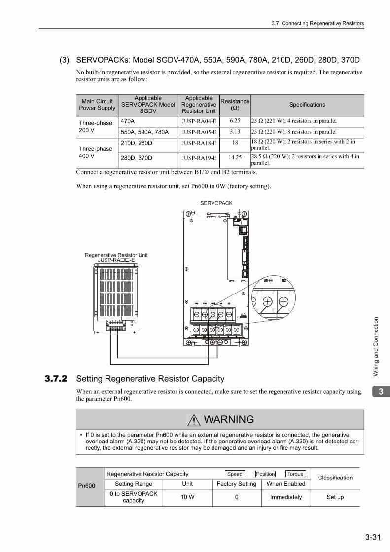
3.7 Connecting Regenerative Resistors
3-31
3
Wirin
g a
nd
Co
nn
ectio
n
(3) SERVOPACKs: Model SGDV-470A, 550A, 590A, 780A, 210D, 260D, 280D, 370DNo built-in regenerative resistor is provided, so the external regenerative resistor is required. The regenerative resistor units are as follow:
Connect a regenerative resistor unit between B1/ and B2 terminals.
When using a regenerative resistor unit, set Pn600 to 0W (factory setting).
3.7.2 Setting Regenerative Resistor CapacityWhen an external regenerative resistor is connected, make sure to set the regenerative resistor capacity using the parameter Pn600.
Main Circuit Power Supply
Applicable SERVOPACK Model
SGDV
Applicable Regenerative Resistor Unit
Resistance (Ω) Specifications
Three-phase 200 V
470A JUSP-RA04-E 6.25 25 Ω (220 W); 4 resistors in parallel
550A, 590A, 780A JUSP-RA05-E 3.13 25 Ω (220 W); 8 resistors in parallel
Three-phase 400 V
210D, 260D JUSP-RA18-E 18 18 Ω (220 W); 2 resistors in series with 2 in parallel.
280D, 370D JUSP-RA19-E 14.25 28.5 Ω (220 W); 2 resistors in series with 4 in parallel.
Regenerative Resistor UnitJUSP-RA��-E
SERVOPACK
WARNING• If 0 is set to the parameter Pn600 while an external regenerative resistor is connected, the generative
overload alarm (A.320) may not be detected. If the generative overload alarm (A.320) is not detected cor-rectly, the external regenerative resistor may be damaged and an injury or fire may result.
Pn600
Regenerative Resistor Capacity Classification
Setting Range Unit Factory Setting When Enabled
0 to SERVOPACK capacity 10 W 0 Immediately Set up
Speed Position Torque
3 Wiring and Connection
3.8.1 Wiring for Noise Control
3-32
Be sure to set this parameter when installing an external regenerative resistor to the SERVOPACK.When set to the factory setting of "0," the SERVOPACK’s built-in resistor has been used.Set the regenerative resistor capacity within tolerance value. When the set value is improper, alarm A.320 is detected.
The set value differs depending on the cooling method of external regenerative resistor:
• For natural convection cooling method: Set the value maximum 20 % of the actually installed regenerative resistor capacity (W).
• For forced convection cooling method: Set the value maximum 50 % of the actually installed regenerative resistor capacity (W).
Example: Set 20 W (100 W × 20 % ) for the 100 W external regenerative resistor with natural convection cooling method:
Pn600 = 2 (units: 10 W)
3.8 Noise Control and Measures for Harmonic SuppressionThis section describes the wiring for noise control and the DC reactor for harmonic suppression.
3.8.1 Wiring for Noise ControlThe SERVOPACK uses high-speed switching elements in the main circuit. It may receive "switching noise" from these high-speed switching elements if wiring or grounding around the SERVOPACK is not appropriate. To prevent this, always wire and ground the SERVOPACK correctly.
To prevent malfunction due to noise, take the following actions:
• Position the input reference device and noise filter as close to the SERVOPACK as possible.• Always install a surge absorber in the relay, solenoid and electromagnetic contactor coils.• The distance between a power line (servomotor main circuit cable) and a signal line must be at least 30 cm.
Do not put the power and signal lines in the same duct or bundle them together.• Do not share the power supply with an electric welder or electrical discharge machine. When the SERVO-
PACK is placed near a high-frequency generator, install a noise filter on the input side of the power supply line. As for the wiring of noise filter, refer to (1) Noise Filter shown below.
• Take the grounding measures correctly. As for the grounding, refer to (2) Correct Grounding.
1. When the external regenerative resistors for power are used at the rated load ratio, the resistor temperature increases to between 200 °C and 300 °C. The resistors must be used at or below the rated values. Check with the manufacturer for the resistor’s load characteristics.
2. For safety, use the external resistors with thermoswitches.
Because the SERVOPACK is designed as an industrial device, it provides no mecha-nism to prevent noise interference.If the equipment is to be used near private houses or may receive noise interference, install a noise filter on the input side of the power supply line.
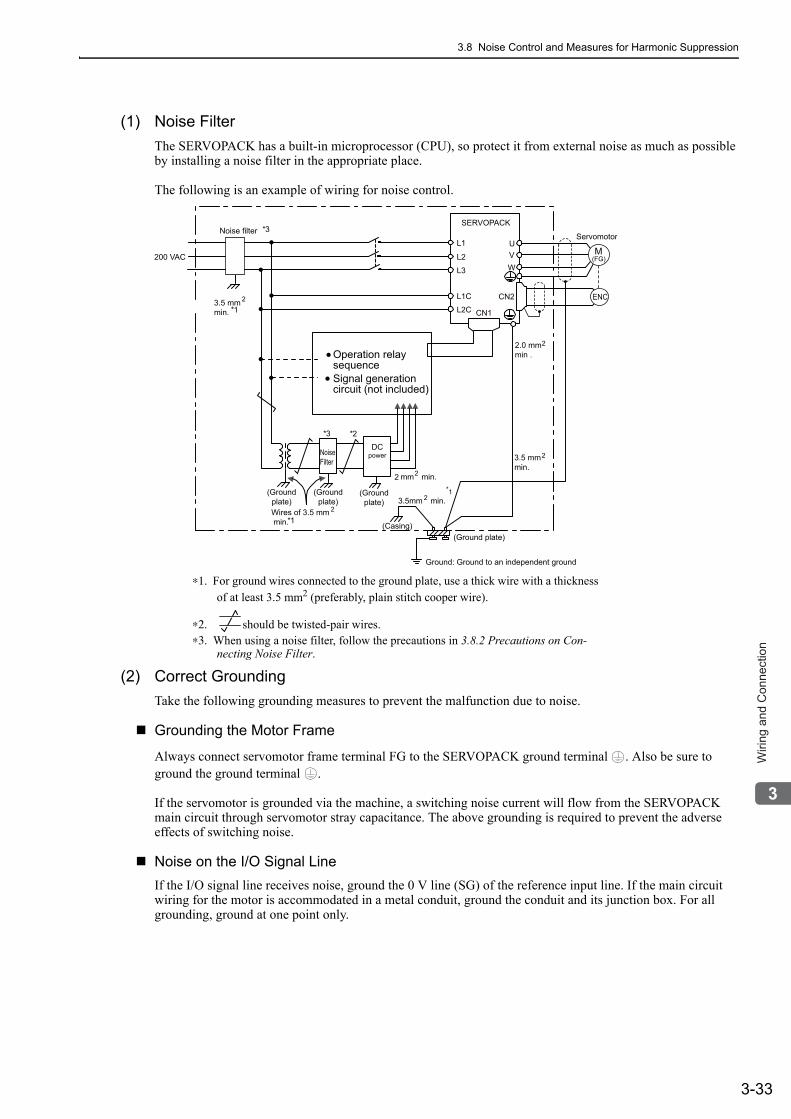
3.8 Noise Control and Measures for Harmonic Suppression
3-33
3
Wirin
g a
nd
Co
nn
ectio
n
(1) Noise FilterThe SERVOPACK has a built-in microprocessor (CPU), so protect it from external noise as much as possible by installing a noise filter in the appropriate place.
The following is an example of wiring for noise control.
∗1. For ground wires connected to the ground plate, use a thick wire with a thickness of at least 3.5 mm2 (preferably, plain stitch cooper wire).
∗2. should be twisted-pair wires.∗3. When using a noise filter, follow the precautions in 3.8.2 Precautions on Con-
necting Noise Filter.
(2) Correct GroundingTake the following grounding measures to prevent the malfunction due to noise.
Grounding the Motor Frame
Always connect servomotor frame terminal FG to the SERVOPACK ground terminal . Also be sure to ground the ground terminal .
If the servomotor is grounded via the machine, a switching noise current will flow from the SERVOPACK main circuit through servomotor stray capacitance. The above grounding is required to prevent the adverse effects of switching noise.
Noise on the I/O Signal LineIf the I/O signal line receives noise, ground the 0 V line (SG) of the reference input line. If the main circuit wiring for the motor is accommodated in a metal conduit, ground the conduit and its junction box. For all grounding, ground at one point only.
U
WVL2
L1
L3
L2C
L1C CN2
CN1
SERVOPACK
Servomotor
Operation relaysequenceSignal generationcircuit (not included)
NoiseFilter
DCpower
(Groundplate)
(Groundplate)
(Groundplate)
(Casing) (Ground plate)
3.5 mmmin.
2
200 VAC
Noise filter *3
*1
*3
*1
*2
2 mm2 min.
3.5mm min. 2*1
2.0 mm2
min .
3.5 mmmin.
2
ENC
(FG)M
Wires of 3.5 mm min.
2
Ground: Ground to an independent ground
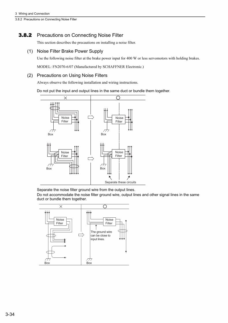
3 Wiring and Connection
3.8.2 Precautions on Connecting Noise Filter
3-34
3.8.2 Precautions on Connecting Noise FilterThis section describes the precautions on installing a noise filter.
(1) Noise Filter Brake Power SupplyUse the following noise filter at the brake power input for 400 W or less servomotors with holding brakes.
MODEL: FN2070-6/07 (Manufactured by SCHAFFNER Electronic.)
(2) Precautions on Using Noise FiltersAlways observe the following installation and wiring instructions.
Do not put the input and output lines in the same duct or bundle them together.
Separate the noise filter ground wire from the output lines.Do not accommodate the noise filter ground wire, output lines and other signal lines in the same duct or bundle them together.
�×
Noise
Filter
Noise
Filter
Separate these circuits
Box
Box
Noise
Filter
Noise
Filter
Box
Box
Noise
Filter
Noise
Filter
�×
The ground wire
can be close to
input lines.
Box Box
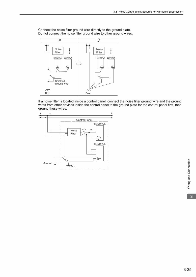
3.8 Noise Control and Measures for Harmonic Suppression
3-35
3
Wirin
g a
nd
Co
nn
ectio
n
Connect the noise filter ground wire directly to the ground plate.Do not connect the noise filter ground wire to other ground wires.
If a noise filter is located inside a control panel, connect the noise filter ground wire and the ground wires from other devices inside the control panel to the ground plate for the control panel first, then ground these wires.
�×
Shielded ground wire
Noise Filter
Noise Filter
Box Box
SERVOPACK SERVOPACK SERVOPACK SERVOPACK
Noise
Filter
Control Panel
Ground
Box
SERVOPACK
SERVOPACK
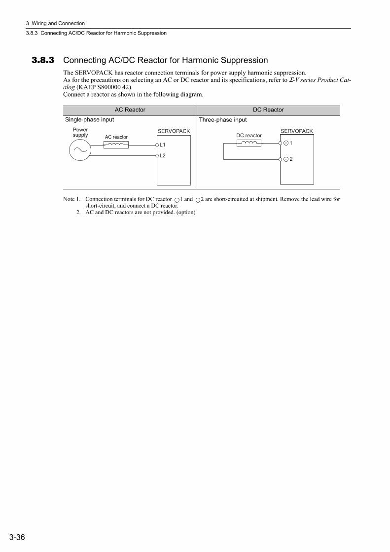
3 Wiring and Connection
3.8.3 Connecting AC/DC Reactor for Harmonic Suppression
3-36
3.8.3 Connecting AC/DC Reactor for Harmonic SuppressionThe SERVOPACK has reactor connection terminals for power supply harmonic suppression.As for the precautions on selecting an AC or DC reactor and its specifications, refer to Σ-V series Product Cat-alog (KAEP S800000 42).Connect a reactor as shown in the following diagram.
Note 1. Connection terminals for DC reactor 1 and 2 are short-circuited at shipment. Remove the lead wire for short-circuit, and connect a DC reactor.
2. AC and DC reactors are not provided. (option)
AC Reactor DC Reactor
Single-phase input Three-phase input
SERVOPACK
L1
L2
AC reactorPowersupply
SERVOPACKDC reactor
1
2
4-1
4
Op
era
tio
n
4Operation
4.1 MECHATROLINK-II Communications Settings . . . . . . . . . . . . . . . . . . . .4-34.1.1 Setting Switches SW1 and SW2 . . . . . . . . . . . . . . . . . . . . . . . . . . . . . . . . . . . . . . . . . 4-3
4.2 MECHATROLINK-II Commands . . . . . . . . . . . . . . . . . . . . . . . . . . . . . . . .4-4
4.3 Setting Common Basic Functions . . . . . . . . . . . . . . . . . . . . . . . . . . . . . . .4-54.3.1 Servomotor Rotation Direction . . . . . . . . . . . . . . . . . . . . . . . . . . . . . . . . . . . . . . . . . . 4-54.3.2 Overtravel . . . . . . . . . . . . . . . . . . . . . . . . . . . . . . . . . . . . . . . . . . . . . . . . . . . . . . . . . . 4-64.3.3 Software Limit Settings . . . . . . . . . . . . . . . . . . . . . . . . . . . . . . . . . . . . . . . . . . . . . . . . 4-94.3.4 Holding Brakes . . . . . . . . . . . . . . . . . . . . . . . . . . . . . . . . . . . . . . . . . . . . . . . . . . . . . 4-104.3.5 Stopping Servomotor after SV_OFF Command or Alarm Occurrence . . . . . . . . . . . 4-144.3.6 Instantaneous Power Interruption Settings . . . . . . . . . . . . . . . . . . . . . . . . . . . . . . . . 4-164.3.7 SEMI-F47 Function (Torque Limit Function for Low Power Supply
Voltage for Main Circuit) . . . . . . . . . . . . . . . . . . . . . . . . . . . . . . . . . . . . . . . . . . . . . . 4-174.3.8 Setting Motor Overload Detection Level . . . . . . . . . . . . . . . . . . . . . . . . . . . . . . . . . . 4-20
4.4 Trial Operation . . . . . . . . . . . . . . . . . . . . . . . . . . . . . . . . . . . . . . . . . . . .4-224.4.1 Inspection and Checking before Trial Operation . . . . . . . . . . . . . . . . . . . . . . . . . . . . 4-224.4.2 Trial Operation via MECHATROLINK-II . . . . . . . . . . . . . . . . . . . . . . . . . . . . . . . . . . 4-234.4.3 Electronic Gear . . . . . . . . . . . . . . . . . . . . . . . . . . . . . . . . . . . . . . . . . . . . . . . . . . . . . 4-244.4.4 Encoder Output Pulses . . . . . . . . . . . . . . . . . . . . . . . . . . . . . . . . . . . . . . . . . . . . . . . 4-274.4.5 Encoder Output Pulse Setting . . . . . . . . . . . . . . . . . . . . . . . . . . . . . . . . . . . . . . . . . . 4-28
4.5 Test Without Motor Function . . . . . . . . . . . . . . . . . . . . . . . . . . . . . . . . . .4-294.5.1 Related Parameters . . . . . . . . . . . . . . . . . . . . . . . . . . . . . . . . . . . . . . . . . . . . . . . . . 4-294.5.2 Limitations . . . . . . . . . . . . . . . . . . . . . . . . . . . . . . . . . . . . . . . . . . . . . . . . . . . . . . . . . 4-294.5.3 Digital Operator Display during Testing without Motor . . . . . . . . . . . . . . . . . . . . . . . 4-31
4.6 Limiting Torque . . . . . . . . . . . . . . . . . . . . . . . . . . . . . . . . . . . . . . . . . . . .4-324.6.1 Internal Torque Limit . . . . . . . . . . . . . . . . . . . . . . . . . . . . . . . . . . . . . . . . . . . . . . . . . 4-324.6.2 External Torque Limit . . . . . . . . . . . . . . . . . . . . . . . . . . . . . . . . . . . . . . . . . . . . . . . . 4-334.6.3 Checking Output Torque Limiting during Operation . . . . . . . . . . . . . . . . . . . . . . . . . 4-34
4 Operation
4-2
4.7 Absolute Encoders . . . . . . . . . . . . . . . . . . . . . . . . . . . . . . . . . . . . . . . . . 4-354.7.1 Encoder Resolutions . . . . . . . . . . . . . . . . . . . . . . . . . . . . . . . . . . . . . . . . . . . . . . . . .4-354.7.2 Absolute Encoder Data Backup . . . . . . . . . . . . . . . . . . . . . . . . . . . . . . . . . . . . . . . . .4-364.7.3 Battery Replacement . . . . . . . . . . . . . . . . . . . . . . . . . . . . . . . . . . . . . . . . . . . . . . . . .4-374.7.4 Absolute Encoder Setup . . . . . . . . . . . . . . . . . . . . . . . . . . . . . . . . . . . . . . . . . . . . . .4-394.7.5 Absolute Encoder Reception Sequence . . . . . . . . . . . . . . . . . . . . . . . . . . . . . . . . . .4-404.7.6 Multiturn Limit Setting . . . . . . . . . . . . . . . . . . . . . . . . . . . . . . . . . . . . . . . . . . . . . . . .4-434.7.7 Multiturn Limit Disagreement Alarm (A.CC0) . . . . . . . . . . . . . . . . . . . . . . . . . . . . . . .4-444.7.8 Absolute Encoder Origin Offset . . . . . . . . . . . . . . . . . . . . . . . . . . . . . . . . . . . . . . . . .4-45
4.8 Safety Function . . . . . . . . . . . . . . . . . . . . . . . . . . . . . . . . . . . . . . . . . . . 4-464.8.1 Hard Wire Base Block (HWBB) Function . . . . . . . . . . . . . . . . . . . . . . . . . . . . . . . . . .4-464.8.2 External Device Monitor (EDM1) . . . . . . . . . . . . . . . . . . . . . . . . . . . . . . . . . . . . . . . .4-514.8.3 Application Example of Safety Functions . . . . . . . . . . . . . . . . . . . . . . . . . . . . . . . . .4-534.8.4 Confirming Safety Functions . . . . . . . . . . . . . . . . . . . . . . . . . . . . . . . . . . . . . . . . . . .4-544.8.5 Connecting a Safety Device . . . . . . . . . . . . . . . . . . . . . . . . . . . . . . . . . . . . . . . . . . .4-554.8.6 Precautions for Safety Functions . . . . . . . . . . . . . . . . . . . . . . . . . . . . . . . . . . . . . . . .4-56
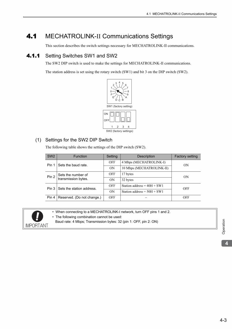
4.1 MECHATROLINK-II Communications Settings
4-3
4
Op
era
tio
n
4.1 MECHATROLINK-II Communications SettingsThis section describes the switch settings necessary for MECHATROLINK-II communications.
4.1.1 Setting Switches SW1 and SW2The SW2 DIP switch is used to make the settings for MECHATROLINK-II communications.
The station address is set using the rotary switch (SW1) and bit 3 on the DIP switch (SW2).
(1) Settings for the SW2 DIP SwitchThe following table shows the settings of the DIP switch (SW2).
ON
OFF
SW2 (factory settings)
43 52 6
1 7
C
80
F 9
E A
D B
SW1 (factory setting)
1 2 3 4
SW2 Function Setting Description Factory setting
Pin 1 Sets the baud rate.OFF 4 Mbps (MECHATROLINK-I)
ONON 10 Mbps (MECHATROLINK-II)
Pin 2 Sets the number of transmission bytes.
OFF 17 bytesON
ON 32 bytes
Pin 3 Sets the station address.OFF Station address = 40H + SW1
OFFON Station address = 50H + SW1
Pin 4 Reserved. (Do not change.) OFF − OFF
• When connecting to a MECHATROLINK-I network, turn OFF pins 1 and 2.• The following combination cannot be used:
Baud rate: 4 Mbps; Transmission bytes: 32 (pin 1: OFF, pin 2: ON)
4 Operation
4.1.1 Setting Switches SW1 and SW2
4-4
(2) Setting the Station AddressThe following table lists the possible settings of the rotary switch (SW1) and bit3 of the DIP switch (SW2) that can be combined to form a station address.
The factory setting for the station address is 41H (SW2 bit 3 = OFF, SW1 = 1).
4.2 MECHATROLINK-II CommandsFor information on the MECHATROLINK-II commands, refer to Σ-V series User’s Manual MECHA-TROLINK-II Command (manual number: SIEP S800000 54).
Bit 3 of SW2 SW1 Station Address Bit 3 of SW2 SW1 Station Address
OFF 0 Disabled ON 0 50H
OFF 1 41H ON 1 51H
OFF 2 42H ON 2 52H
OFF 3 43H ON 3 53H
OFF 4 44H ON 4 54H
OFF 5 45H ON 5 55H
OFF 6 46H ON 6 56H
OFF 7 47H ON 7 57H
OFF 8 48H ON 8 58H
OFF 9 49H ON 9 59H
OFF A 4AH ON A 5AH
OFF B 4BH ON B 5BH
OFF C 4CH ON C 5CH
OFF D 4DH ON D 5DH
OFF E 4EH ON E 5EH
OFF F 4FH ON F 5FH
• Turn the power OFF and then ON again to validate the new settings.
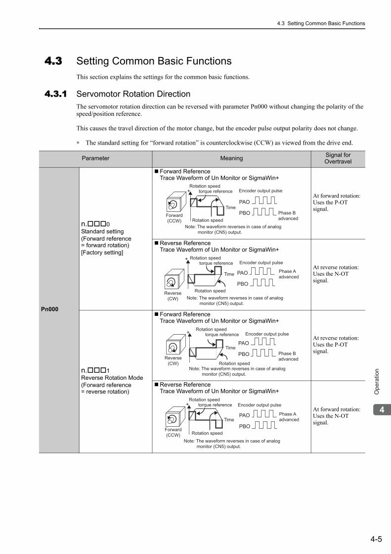
4.3 Setting Common Basic Functions
4-5
4
Op
era
tio
n
4.3 Setting Common Basic FunctionsThis section explains the settings for the common basic functions.
4.3.1 Servomotor Rotation DirectionThe servomotor rotation direction can be reversed with parameter Pn000 without changing the polarity of the speed/position reference.
This causes the travel direction of the motor change, but the encoder pulse output polarity does not change.
∗ The standard setting for “forward rotation” is counterclockwise (CCW) as viewed from the drive end.
Parameter Meaning Signal for Overtravel
Pn000
n. 0Standard setting(Forward reference= forward rotation)[Factory setting]
Forward ReferenceTrace Waveform of Un Monitor or SigmaWin+
At forward rotation:Uses the P-OTsignal.
Reverse ReferenceTrace Waveform of Un Monitor or SigmaWin+
At reverse rotation:Uses the N-OTsignal.
n. 1Reverse Rotation Mode(Forward reference= reverse rotation)
Forward ReferenceTrace Waveform of Un Monitor or SigmaWin+
At reverse rotation:Uses the P-OTsignal.
Reverse ReferenceTrace Waveform of Un Monitor or SigmaWin+
At forward rotation:Uses the N-OTsignal.
Forward(CCW)
Phase Badvanced
Time
Encoder output pulse
PAO
PBO
Note: The waveform reverses in case of analog monitor (CN5) output.
Rotation speedtorque reference
Rotation speed
+
Reverse(CW)
Phase AadvancedTime
Encoder output pulse
Note: The waveform reverses in case of analog monitor (CN5) output.
Rotation speedtorque reference
Rotation speed
PAO
PBO
+
PAO
PBO
+
Reverse(CW)
Phase Badvanced
Time
Encoder output pulse
Note: The waveform reverses in case of analog monitor (CN5) output.
Rotation speedtorque reference
Rotation speed
Forward(CCW)
Phase Aadvanced
Encoder output pulse
Note: The waveform reverses in case of analog monitor (CN5) output.
Rotation speedtorque reference
Rotation speed
PAO
PBO
+
Time
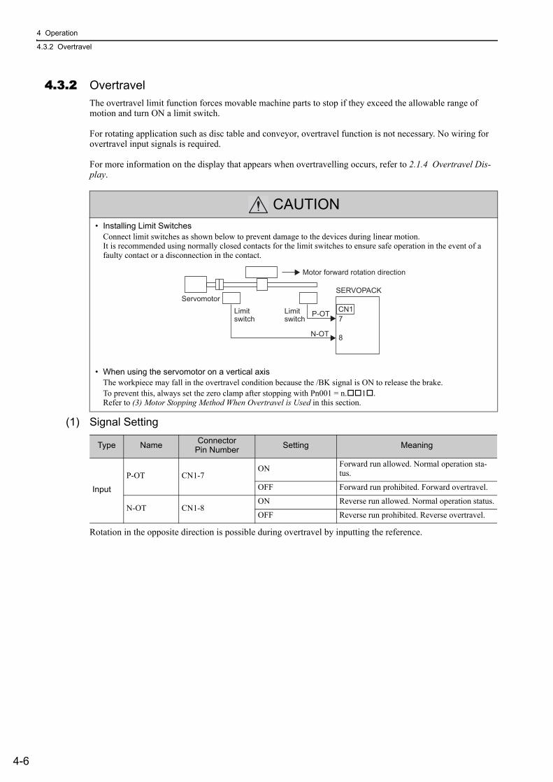
4 Operation
4.3.2 Overtravel
4-6
4.3.2 OvertravelThe overtravel limit function forces movable machine parts to stop if they exceed the allowable range of motion and turn ON a limit switch.
For rotating application such as disc table and conveyor, overtravel function is not necessary. No wiring for overtravel input signals is required.
For more information on the display that appears when overtravelling occurs, refer to 2.1.4 Overtravel Dis-play.
(1) Signal Setting
Rotation in the opposite direction is possible during overtravel by inputting the reference.
CAUTION• Installing Limit Switches
Connect limit switches as shown below to prevent damage to the devices during linear motion.It is recommended using normally closed contacts for the limit switches to ensure safe operation in the event of a faulty contact or a disconnection in the contact.
• When using the servomotor on a vertical axisThe workpiece may fall in the overtravel condition because the /BK signal is ON to release the brake.To prevent this, always set the zero clamp after stopping with Pn001 = n. 1 .Refer to (3) Motor Stopping Method When Overtravel is Used in this section.
Limit
switch
Servomotor
SERVOPACK
7
CN1
8N-OT
P-OTLimit
switch
Motor forward rotation direction
Type Name ConnectorPin Number Setting Meaning
Input
P-OT CN1-7ON Forward run allowed. Normal operation sta-
tus.
OFF Forward run prohibited. Forward overtravel.
N-OT CN1-8ON Reverse run allowed. Normal operation status.
OFF Reverse run prohibited. Reverse overtravel.
4.3 Setting Common Basic Functions
4-7
4
Op
era
tio
n
(2) Overtravel Function SettingParameters Pn50A and Pn50B can be set to enable or disable the overtravel function.
If the overtravel function is not used, no wiring for overtravel input signals will be required.
• A parameter can be used to re-allocate input connector number for the P-OT and N-OT signals. Refer to 3.3.1 Input Signal Allocations.
(3) Motor Stopping Method When Overtravel is UsedThere are three motor stopping methods when an overtravel is used.
• Dynamic brakeBy short-circuiting the electric circuits, the servomotor comes to a quick stop.
• Decelerate to stopStops by using deceleration (braking) torque.
• Coast to a stopStops naturally, with no control, by using the friction resistance of the motor in operation.
After stopping, there are two modes.
• Coast modeStopped naturally, with no control, by using the friction resistance of the motor in operation.
• Zero clamp modeA mode forms a position loop by using the position reference zero.
The stopping method when an overtravel (P-OT, N-OT) signal is input while the servomotor is operating can be set with parameter Pn001.
Parameter Meaning When Enabled Classification
Pn50An.2
Inputs the Forward Run Prohibited (P-OT) signal from CN1-7.[Factory setting]
After restart Setupn.8 Disables the Forward Run Prohibited (P-OT) signal.
Allows constant forward rotation.
Pn50Bn. 3
Inputs the Reverse Run Prohibited (N-OT) signal from CN1-8. [Factory setting]
n. 8 Disables the Reverse Run Prohibited (N-OT) signal. Allows constant reverse rotation.
Parameter Stop ModeMode After
StoppingMeaning When Enabled Classification
Pn001
n. 00 Stop by dynamic brake
Coast
Immediately stops the ser-vomotor by dynamic brak-ing (DB), then places it into Coast Mode.
After restart Setup
n. 01
n. 02 Coast to a stop
Stops the servomotor by coast stop, then places it into Coast Mode.
n. 1
Decelerate to stop
Zero Clamp
Decelerates the servomotor with emergency stop torque (Pn406), then places it into Zero Clamp (Servolock) Mode.
n. 2 Coast
Decelerates the servomotor with emergency stop torque (Pn406), then places it into Coast Mode.
4 Operation
4.3.2 Overtravel
4-8
• A servomotor under torque control cannot be decelerated to a stop. The servomotor is stopped with the dynamic braking (DB) or coasts to a stop according to the setting of Pn001.0. After the servomotor stops, the servomotor will enter a coast state.
• For details on stopping methods after the SV_OFF command is received or an alarm occurs, refer to 4.3.5 Stopping Servomotor after SV_OFF Command or Alarm Occurrence.
When Motor Stopping Method is Set to Decelerate to StopEmergency stop torque can be set with Pn406.
• The setting unit is a percentage of the rated torque.• The factory setting is 800% so that the setting is large enough a value to operate the servomotor at maximum
torque. The maximum value of emergency stop torque that is actually available, however, is limited to the maximum torque of the servomotor.
Pn406Emergency Stop Torque Classification
Setting Range Setting Unit Factory Setting When Enabled
0 to 800 1% 800 Immediately Setup
Speed Position
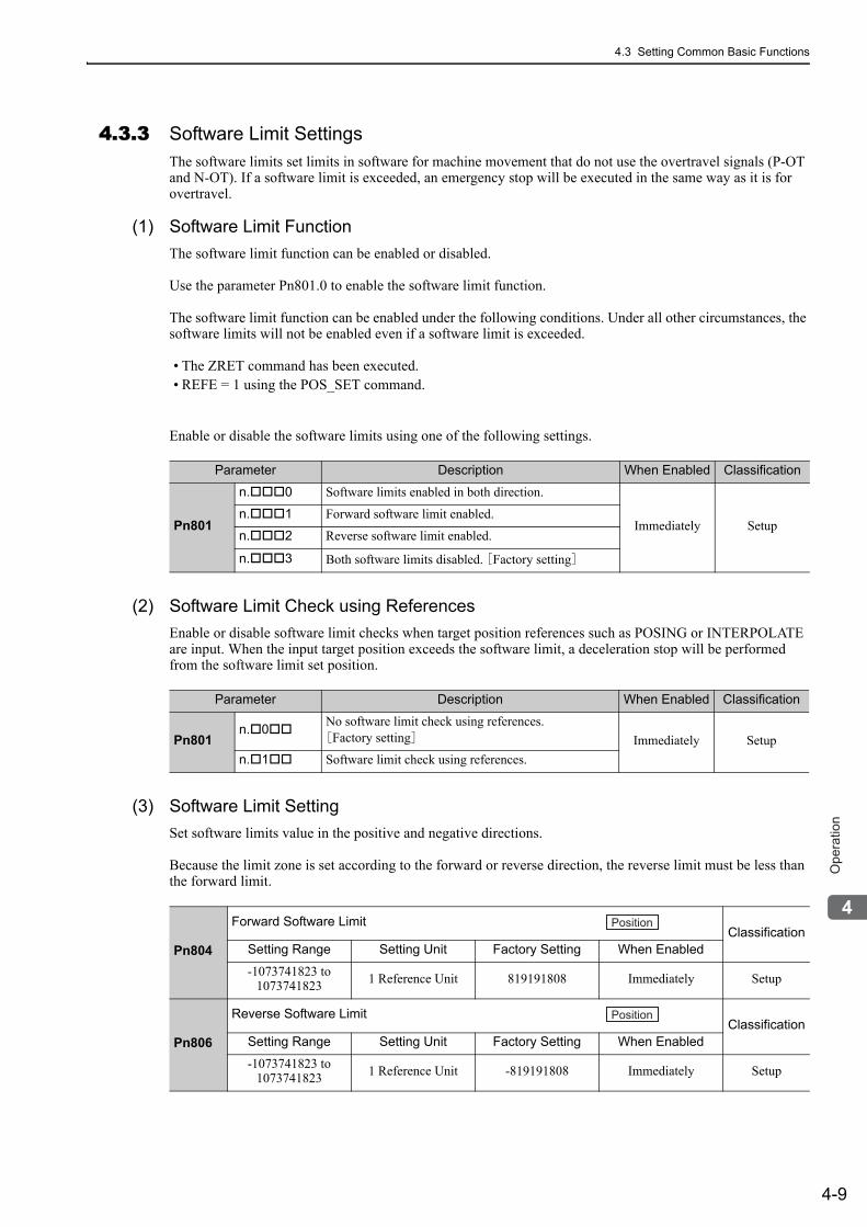
4.3 Setting Common Basic Functions
4-9
4
Op
era
tio
n
4.3.3 Software Limit SettingsThe software limits set limits in software for machine movement that do not use the overtravel signals (P-OT and N-OT). If a software limit is exceeded, an emergency stop will be executed in the same way as it is for overtravel.
(1) Software Limit FunctionThe software limit function can be enabled or disabled.
Use the parameter Pn801.0 to enable the software limit function.
The software limit function can be enabled under the following conditions. Under all other circumstances, the software limits will not be enabled even if a software limit is exceeded.
• The ZRET command has been executed.• REFE = 1 using the POS_SET command.
Enable or disable the software limits using one of the following settings.
(2) Software Limit Check using References Enable or disable software limit checks when target position references such as POSING or INTERPOLATE are input. When the input target position exceeds the software limit, a deceleration stop will be performed from the software limit set position.
(3) Software Limit SettingSet software limits value in the positive and negative directions.
Because the limit zone is set according to the forward or reverse direction, the reverse limit must be less than the forward limit.
Parameter Description When Enabled Classification
Pn801
n. 0 Software limits enabled in both direction.
Immediately Setupn. 1 Forward software limit enabled.
n. 2 Reverse software limit enabled.
n. 3 Both software limits disabled. [Factory setting]
Parameter Description When Enabled Classification
Pn801n. 0 No software limit check using references.
[Factory setting] Immediately Setupn. 1 Software limit check using references.
Pn804
Forward Software LimitClassification
Setting Range Setting Unit Factory Setting When Enabled
-1073741823 to 1073741823 1 Reference Unit 819191808 Immediately Setup
Pn806
Reverse Software LimitClassification
Setting Range Setting Unit Factory Setting When Enabled
-1073741823 to 1073741823 1 Reference Unit -819191808 Immediately Setup
Position
Position
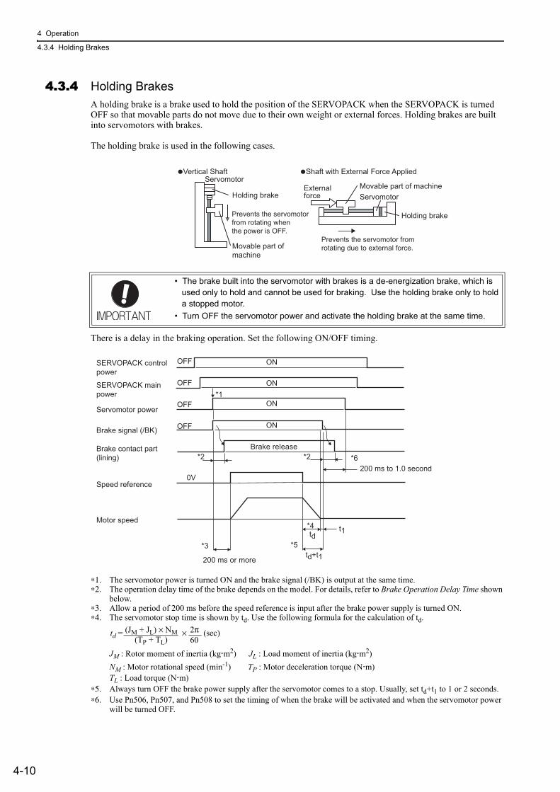
4 Operation
4.3.4 Holding Brakes
4-10
4.3.4 Holding BrakesA holding brake is a brake used to hold the position of the SERVOPACK when the SERVOPACK is turned OFF so that movable parts do not move due to their own weight or external forces. Holding brakes are built into servomotors with brakes.
The holding brake is used in the following cases.
There is a delay in the braking operation. Set the following ON/OFF timing.
∗1. The servomotor power is turned ON and the brake signal (/BK) is output at the same time.∗2. The operation delay time of the brake depends on the model. For details, refer to Brake Operation Delay Time shown
below.∗3. Allow a period of 200 ms before the speed reference is input after the brake power supply is turned ON.∗4. The servomotor stop time is shown by td. Use the following formula for the calculation of td.
JM : Rotor moment of inertia (kg m2) JL : Load moment of inertia (kg m2)NM : Motor rotational speed (min-1) TP : Motor deceleration torque (N m)TL : Load torque (N m)
∗5. Always turn OFF the brake power supply after the servomotor comes to a stop. Usually, set td+t1 to 1 or 2 seconds.∗6. Use Pn506, Pn507, and Pn508 to set the timing of when the brake will be activated and when the servomotor power
will be turned OFF.
• The brake built into the servomotor with brakes is a de-energization brake, which is used only to hold and cannot be used for braking. Use the holding brake only to hold a stopped motor.
• Turn OFF the servomotor power and activate the holding brake at the same time.
Servomotor
�Vertical Shaft
Holding brake
Prevents the servomotor
from rotating when
the power is OFF.
�Shaft with External Force Applied
Movable part of machine
Holding brake
Movable part of
machine
Servomotor
External
force
Prevents the servomotor from
rotating due to external force.
OFF
OFF
OFF
OFF
Brake release
ON
ON
ON
ON
*1
*2
*4
*5
*6
*3
200 ms or more
200 ms to 1.0 second0V
*2
SERVOPACK mainpower
SERVOPACK controlpower
Servomotor power
Brake signal (/BK)
Brake contact part(lining)
Speed reference
Motor speed
td
td+t1
t1
td = × (sec)(TP + TL)
(JM + JL) × NM 2π60
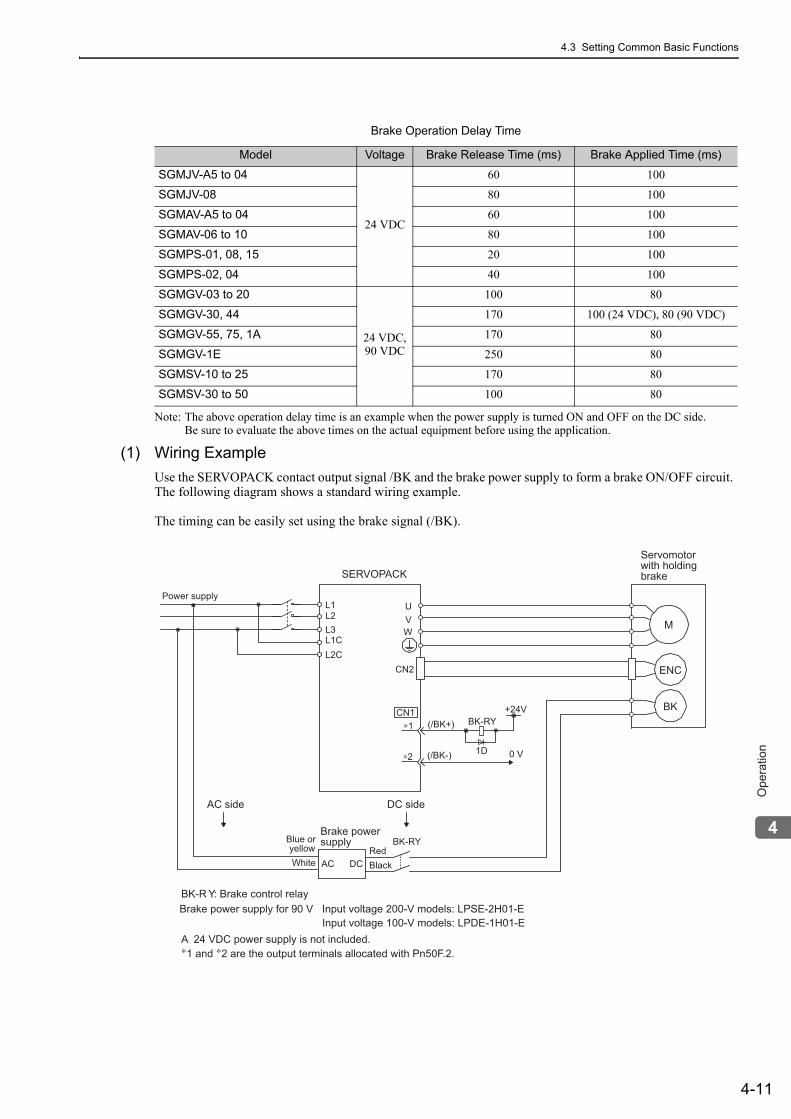
4.3 Setting Common Basic Functions
4-11
4
Op
era
tio
n
Note: The above operation delay time is an example when the power supply is turned ON and OFF on the DC side.Be sure to evaluate the above times on the actual equipment before using the application.
(1) Wiring ExampleUse the SERVOPACK contact output signal /BK and the brake power supply to form a brake ON/OFF circuit. The following diagram shows a standard wiring example.
The timing can be easily set using the brake signal (/BK).
Brake Operation Delay Time
Model Voltage Brake Release Time (ms) Brake Applied Time (ms)
SGMJV-A5 to 04
24 VDC
60 100
SGMJV-08 80 100
SGMAV-A5 to 04 60 100
SGMAV-06 to 10 80 100
SGMPS-01, 08, 15 20 100
SGMPS-02, 04 40 100
SGMGV-03 to 20
24 VDC,90 VDC
100 80
SGMGV-30, 44 170 100 (24 VDC), 80 (90 VDC)
SGMGV-55, 75, 1A 170 80
SGMGV-1E 250 80
SGMSV-10 to 25 170 80
SGMSV-30 to 50 100 80
BK-R Y: Brake control relay
∗1 and ∗2 are the output terminals allocated with Pn50F.2.A 24 VDC power supply is not included.
Brake power supply for 90 V Input voltage 200-V models: LPSE-2H01-EInput voltage 100-V models: LPDE-1H01-E
M
BK
ENC
UVW
CN2
AC DC
BK-RY
BK-RY
+24V
L1L2L3L1CL2C
(/BK+)
(/BK-)
CN1∗1
∗2 1D 0 V
Servomotorwith holdingbrakeSERVOPACK
Power supply
RedBlack
Blue or yellowWhite
Brake powersupply
DC sideAC side
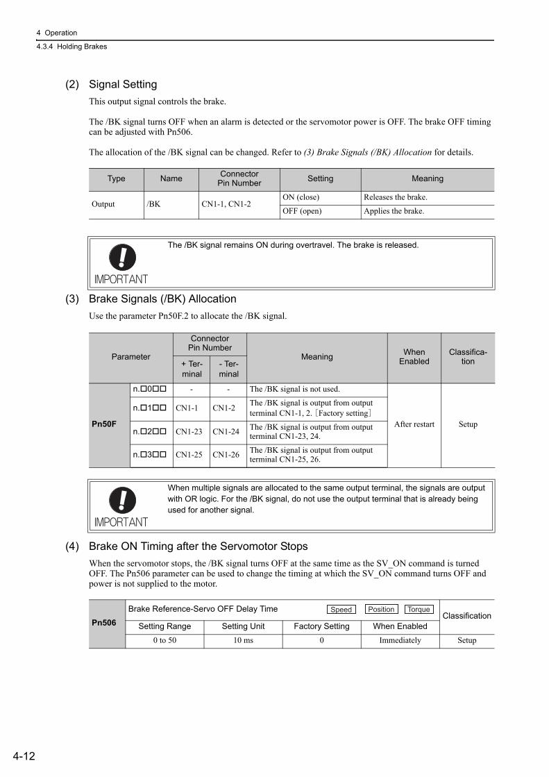
4 Operation
4.3.4 Holding Brakes
4-12
(2) Signal SettingThis output signal controls the brake.
The /BK signal turns OFF when an alarm is detected or the servomotor power is OFF. The brake OFF timing can be adjusted with Pn506.
The allocation of the /BK signal can be changed. Refer to (3) Brake Signals (/BK) Allocation for details.
(3) Brake Signals (/BK) AllocationUse the parameter Pn50F.2 to allocate the /BK signal.
(4) Brake ON Timing after the Servomotor StopsWhen the servomotor stops, the /BK signal turns OFF at the same time as the SV_ON command is turned OFF. The Pn506 parameter can be used to change the timing at which the SV_ON command turns OFF and power is not supplied to the motor.
Type Name Connector Pin Number Setting Meaning
Output /BK CN1-1, CN1-2ON (close) Releases the brake.
OFF (open) Applies the brake.
The /BK signal remains ON during overtravel. The brake is released.
Parameter
Connector Pin Number
Meaning WhenEnabled
Classifica-tion+ Ter-
minal- Ter-minal
Pn50F
n. 0 - - The /BK signal is not used.
After restart Setup
n. 1 CN1-1 CN1-2 The /BK signal is output from output terminal CN1-1, 2. [Factory setting]
n. 2 CN1-23 CN1-24 The /BK signal is output from output terminal CN1-23, 24.
n. 3 CN1-25 CN1-26 The /BK signal is output from output terminal CN1-25, 26.
When multiple signals are allocated to the same output terminal, the signals are output with OR logic. For the /BK signal, do not use the output terminal that is already being used for another signal.
Pn506Brake Reference-Servo OFF Delay Time
ClassificationSetting Range Setting Unit Factory Setting When Enabled
0 to 50 10 ms 0 Immediately Setup
Speed Position Torque
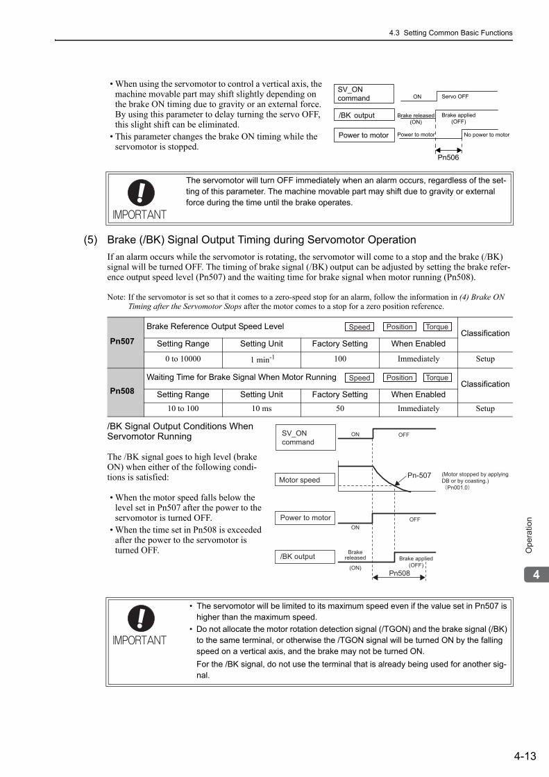
4.3 Setting Common Basic Functions
4-13
4
Op
era
tio
n
• When using the servomotor to control a vertical axis, the machine movable part may shift slightly depending on the brake ON timing due to gravity or an external force. By using this parameter to delay turning the servo OFF, this slight shift can be eliminated.
• This parameter changes the brake ON timing while the servomotor is stopped.
(5) Brake (/BK) Signal Output Timing during Servomotor OperationIf an alarm occurs while the servomotor is rotating, the servomotor will come to a stop and the brake (/BK) signal will be turned OFF. The timing of brake signal (/BK) output can be adjusted by setting the brake refer-ence output speed level (Pn507) and the waiting time for brake signal when motor running (Pn508).
Note: If the servomotor is set so that it comes to a zero-speed stop for an alarm, follow the information in (4) Brake ON Timing after the Servomotor Stops after the motor comes to a stop for a zero position reference.
/BK Signal Output Conditions When Servomotor Running
The /BK signal goes to high level (brake ON) when either of the following condi-tions is satisfied:
• When the motor speed falls below the level set in Pn507 after the power to the servomotor is turned OFF.
• When the time set in Pn508 is exceeded after the power to the servomotor is turned OFF.
The servomotor will turn OFF immediately when an alarm occurs, regardless of the set-ting of this parameter. The machine movable part may shift due to gravity or external force during the time until the brake operates.
SV_ON
command
/BK output
Power to motor
Brake released
(ON)
ON
Power to motor
Brake applied
(OFF)
Servo OFF
No power to motor
Pn506
Pn507
Brake Reference Output Speed LevelClassification
Setting Range Setting Unit Factory Setting When Enabled
0 to 10000 1 min-1 100 Immediately Setup
Pn508Waiting Time for Brake Signal When Motor Running
ClassificationSetting Range Setting Unit Factory Setting When Enabled
10 to 100 10 ms 50 Immediately Setup
• The servomotor will be limited to its maximum speed even if the value set in Pn507 is higher than the maximum speed.
• Do not allocate the motor rotation detection signal (/TGON) and the brake signal (/BK) to the same terminal, or otherwise the /TGON signal will be turned ON by the falling speed on a vertical axis, and the brake may not be turned ON.For the /BK signal, do not use the terminal that is already being used for another sig-nal.
Speed Position Torque
Speed Position Torque
SV_ON command
Motor speed Pn-507
ON OFF
(Motor stopped by applying DB or by coasting.)
Pn001.0
Pn508
Power to motorON
OFF
/BK outputBrake
released
(ON)
Brake applied(OFF)
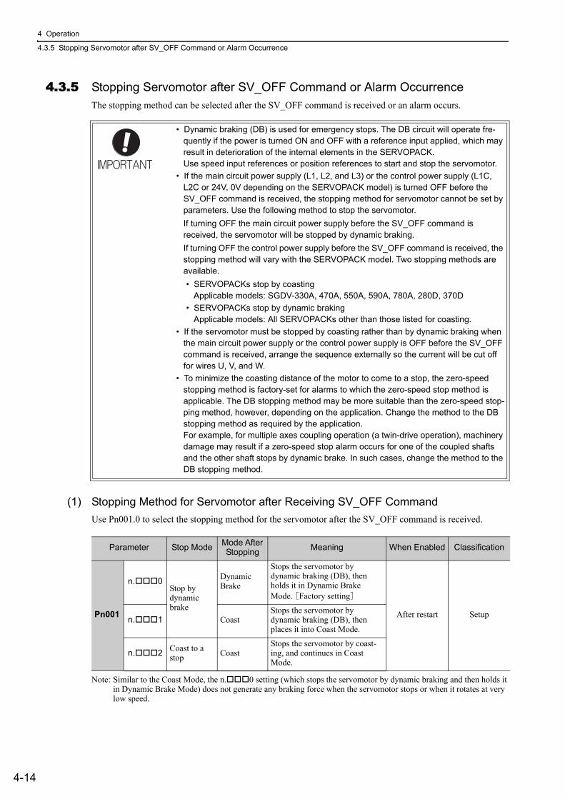
4 Operation
4.3.5 Stopping Servomotor after SV_OFF Command or Alarm Occurrence
4-14
4.3.5 Stopping Servomotor after SV_OFF Command or Alarm OccurrenceThe stopping method can be selected after the SV_OFF command is received or an alarm occurs.
(1) Stopping Method for Servomotor after Receiving SV_OFF CommandUse Pn001.0 to select the stopping method for the servomotor after the SV_OFF command is received.
Note: Similar to the Coast Mode, the n. 0 setting (which stops the servomotor by dynamic braking and then holds it in Dynamic Brake Mode) does not generate any braking force when the servomotor stops or when it rotates at very low speed.
• Dynamic braking (DB) is used for emergency stops. The DB circuit will operate fre-quently if the power is turned ON and OFF with a reference input applied, which may result in deterioration of the internal elements in the SERVOPACK.Use speed input references or position references to start and stop the servomotor.
• If the main circuit power supply (L1, L2, and L3) or the control power supply (L1C, L2C or 24V, 0V depending on the SERVOPACK model) is turned OFF before the SV_OFF command is received, the stopping method for servomotor cannot be set by parameters. Use the following method to stop the servomotor.If turning OFF the main circuit power supply before the SV_OFF command is received, the servomotor will be stopped by dynamic braking.If turning OFF the control power supply before the SV_OFF command is received, the stopping method will vary with the SERVOPACK model. Two stopping methods are available.• SERVOPACKs stop by coasting
Applicable models: SGDV-330A, 470A, 550A, 590A, 780A, 280D, 370D• SERVOPACKs stop by dynamic braking
Applicable models: All SERVOPACKs other than those listed for coasting.• If the servomotor must be stopped by coasting rather than by dynamic braking when
the main circuit power supply or the control power supply is OFF before the SV_OFF command is received, arrange the sequence externally so the current will be cut off for wires U, V, and W.
• To minimize the coasting distance of the motor to come to a stop, the zero-speed stopping method is factory-set for alarms to which the zero-speed stop method is applicable. The DB stopping method may be more suitable than the zero-speed stop-ping method, however, depending on the application. Change the method to the DB stopping method as required by the application.For example, for multiple axes coupling operation (a twin-drive operation), machinery damage may result if a zero-speed stop alarm occurs for one of the coupled shafts and the other shaft stops by dynamic brake. In such cases, change the method to the DB stopping method.
Parameter Stop Mode Mode After Stopping Meaning When Enabled Classification
Pn001
n. 0Stop by dynamic brake
Dynamic Brake
Stops the servomotor by dynamic braking (DB), then holds it in Dynamic Brake Mode. [Factory setting]
After restart Setupn. 1 CoastStops the servomotor by dynamic braking (DB), then places it into Coast Mode.
n. 2 Coast to a stop Coast
Stops the servomotor by coast-ing, and continues in Coast Mode.
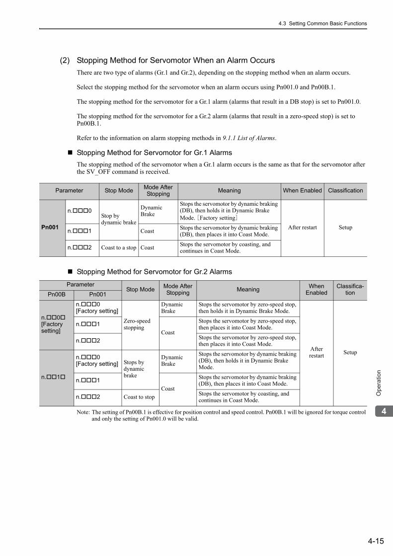
4.3 Setting Common Basic Functions
4-15
4
Op
era
tio
n
(2) Stopping Method for Servomotor When an Alarm OccursThere are two type of alarms (Gr.1 and Gr.2), depending on the stopping method when an alarm occurs.
Select the stopping method for the servomotor when an alarm occurs using Pn001.0 and Pn00B.1.
The stopping method for the servomotor for a Gr.1 alarm (alarms that result in a DB stop) is set to Pn001.0.
The stopping method for the servomotor for a Gr.2 alarm (alarms that result in a zero-speed stop) is set to Pn00B.1.
Refer to the information on alarm stopping methods in 9.1.1 List of Alarms.
Stopping Method for Servomotor for Gr.1 AlarmsThe stopping method of the servomotor when a Gr.1 alarm occurs is the same as that for the servomotor after the SV_OFF command is received.
Stopping Method for Servomotor for Gr.2 Alarms
Note: The setting of Pn00B.1 is effective for position control and speed control. Pn00B.1 will be ignored for torque control and only the setting of Pn001.0 will be valid.
Parameter Stop Mode Mode After Stopping Meaning When Enabled Classification
Pn001
n. 0Stop by dynamic brake
Dynamic Brake
Stops the servomotor by dynamic braking (DB), then holds it in Dynamic Brake Mode. [Factory setting]
After restart Setupn. 1 Coast Stops the servomotor by dynamic braking (DB), then places it into Coast Mode.
n. 2 Coast to a stop Coast Stops the servomotor by coasting, and continues in Coast Mode.
ParameterStop Mode Mode After
Stopping Meaning WhenEnabled
Classifica-tionPn00B Pn001
n. 0[Factory setting]
n. 0[Factory setting]
Zero-speedstopping
Dynamic Brake
Stops the servomotor by zero-speed stop, then holds it in Dynamic Brake Mode.
Afterrestart Setup
n. 1Coast
Stops the servomotor by zero-speed stop, then places it into Coast Mode.
n. 2 Stops the servomotor by zero-speed stop, then places it into Coast Mode.
n. 1
n. 0[Factory setting] Stops by
dynamic brake
Dynamic Brake
Stops the servomotor by dynamic braking (DB), then holds it in Dynamic Brake Mode.
n. 1Coast
Stops the servomotor by dynamic braking (DB), then places it into Coast Mode.
n. 2 Coast to stop Stops the servomotor by coasting, and continues in Coast Mode.
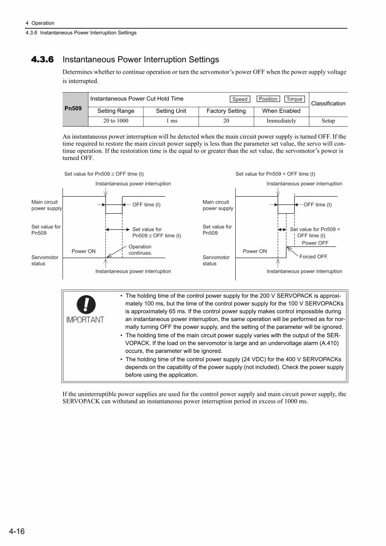
4 Operation
4.3.6 Instantaneous Power Interruption Settings
4-16
4.3.6 Instantaneous Power Interruption SettingsDetermines whether to continue operation or turn the servomotor’s power OFF when the power supply voltage is interrupted.
An instantaneous power interruption will be detected when the main circuit power supply is turned OFF. If the time required to restore the main circuit power supply is less than the parameter set value, the servo will con-tinue operation. If the restoration time is the equal to or greater than the set value, the servomotor’s power is turned OFF.
If the uninterruptible power supplies are used for the control power supply and main circuit power supply, the SERVOPACK can withstand an instantaneous power interruption period in excess of 1000 ms.
Pn509Instantaneous Power Cut Hold Time
ClassificationSetting Range Setting Unit Factory Setting When Enabled
20 to 1000 1 ms 20 Immediately Setup
• The holding time of the control power supply for the 200 V SERVOPACK is approxi-mately 100 ms, but the time of the control power supply for the 100 V SERVOPACKs is approximately 65 ms. If the control power supply makes control impossible during an instantaneous power interruption, the same operation will be performed as for nor-mally turning OFF the power supply, and the setting of the parameter will be ignored.
• The holding time of the main circuit power supply varies with the output of the SER-VOPACK. If the load on the servomotor is large and an undervoltage alarm (A.410) occurs, the parameter will be ignored.
• The holding time of the control power supply (24 VDC) for the 400 V SERVOPACKs depends on the capability of the power supply (not included). Check the power supply before using the application.
Speed Position Torque
Instantaneous power interruption
Set value for Pn509 ≥ OFF time (t)
Instantaneous power interruption
OFF time (t)
Power OFF
Set value forPn509 ≥ OFF time (t)
Set value for Pn509 < OFF time (t)
Main circuitpower supply
Set value forPn509
Servomotorstatus
Power ON
Instantaneous power interruption
Set value for Pn509 < OFF time (t)
Instantaneous power interruption
Forced OFF.
OFF time (t)Main circuitpower supply
Set value forPn509
Servomotorstatus
Power ONOperation continues.
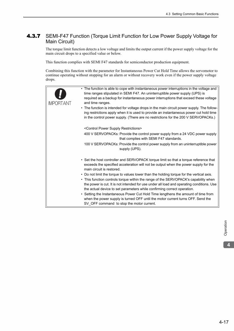
4.3 Setting Common Basic Functions
4-17
4
Op
era
tio
n
4.3.7 SEMI-F47 Function (Torque Limit Function for Low Power Supply Voltage for Main Circuit)The torque limit function detects a low voltage and limits the output current if the power supply voltage for the main circuit drops to a specified value or below.
This function complies with SEMI F47 standards for semiconductor production equipment.
Combining this function with the parameter for Instantaneous Power Cut Hold Time allows the servomotor to continue operating without stopping for an alarm or without recovery work even if the power supply voltage drops.
• The function is able to cope with instantaneous power interruptions in the voltage and time ranges stipulated in SEMI F47. An uninterruptible power supply (UPS) is required as a backup for instantaneous power interruptions that exceed these voltage and time ranges.
• The function is intended for voltage drops in the main circuit power supply. The follow-ing restrictions apply when it is used to provide an instantaneous power cut hold time in the control power supply. (There are no restrictions for the 200 V SERVOPACKs.)
<Control Power Supply Restrictions>400 V SERVOPACKs: Provide the control power supply from a 24 VDC power supply that complies with SEMI F47 standards.100 V SERVOPACKs: Provide the control power supply from an uninterruptible power supply (UPS).
• Set the host controller and SERVOPACK torque limit so that a torque reference that exceeds the specified acceleration will not be output when the power supply for the main circuit is restored.
• Do not limit the torque to values lower than the holding torque for the vertical axis.• This function controls torque within the range of the SERVOPACK's capability when
the power is cut. It is not intended for use under all load and operating conditions. Use the actual device to set parameters while confirming correct operation.
• Setting the Instantaneous Power Cut Hold Time lengthens the amount of time from when the power supply is turned OFF until the motor current turns OFF. Send the SV_OFF command to stop the motor current.
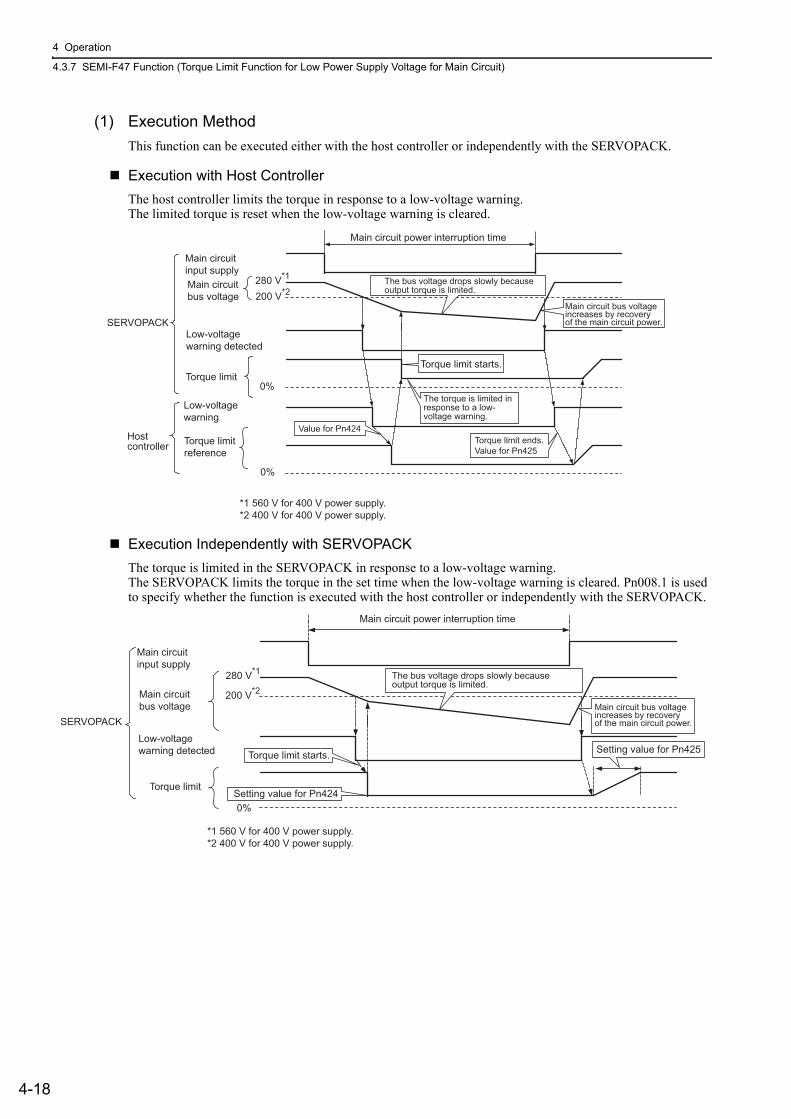
4 Operation
4.3.7 SEMI-F47 Function (Torque Limit Function for Low Power Supply Voltage for Main Circuit)
4-18
(1) Execution MethodThis function can be executed either with the host controller or independently with the SERVOPACK.
Execution with Host ControllerThe host controller limits the torque in response to a low-voltage warning.The limited torque is reset when the low-voltage warning is cleared.
Execution Independently with SERVOPACKThe torque is limited in the SERVOPACK in response to a low-voltage warning.The SERVOPACK limits the torque in the set time when the low-voltage warning is cleared. Pn008.1 is used to specify whether the function is executed with the host controller or independently with the SERVOPACK.
Main circuit power interruption time
Main circuitinput supplyMain circuitbus voltage
Low-voltagewarning detected
Torque limitreference
280 V*1
200 V*2
Low-voltagewarning
Torque limit
SERVOPACK
Hostcontroller
Torque limit starts.
0%
0%
Torque limit ends.Value for Pn425
Value for Pn424
Main circuit bus voltageincreases by recoveryof the main circuit power.
The bus voltage drops slowly becauseoutput torque is limited.
The torque is limited in response to a low-voltage warning.
*1 560 V for 400 V power supply.*2 400 V for 400 V power supply.
280 V*1
200 V*2
0%
Main circuit power interruption time
Main circuitinput supply
Main circuitbus voltage
Low-voltagewarning detected Torque limit starts.
Setting value for Pn424
Setting value for Pn425
Torque limit
SERVOPACKMain circuit bus voltageincreases by recoveryof the main circuit power.
The bus voltage drops slowly becauseoutput torque is limited.
*1 560 V for 400 V power supply.*2 400 V for 400 V power supply.
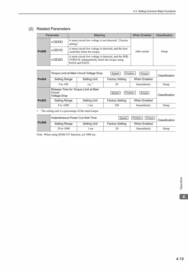
4.3 Setting Common Basic Functions
4-19
4
Op
era
tio
n
(2) Related Parameters
∗ The setting unit is a percentage of the rated torque.
Note: When using SEMI F47 function, set 1000 ms.
Parameter Meaning When Enabled Classification
Pn008
n. 0 A main circuit low voltage is not detected. [Factory setting]
After restart Setupn. 1 A main circuit low voltage is detected, and the host controller limits the torque.
n. 2A main circuit low voltage is detected, and the SER-VOPACK independently limits the torque using Pn424 and Pn425.
Torque Limit at Main Circuit Voltage Drop ClassificationPn424 Setting Range Setting Unit Factory Setting When Enabled
0 to 100 1% ∗ 50 Immediately Setup
Release Time for Torque Limit at Main CircuitVoltage Drop
Classification
Pn425 Setting Range Setting Unit Factory Setting When Enabled
0 to 1000 1 ms 100 Immediately Setup
Pn509Instantaneous Power Cut Hold Time
ClassificationSetting Range Setting Unit Factory Setting When Enabled
20 to 1000 1 ms 20 Immediately Setup
Speed Position Torque
Speed Position Torque
Speed Position Torque
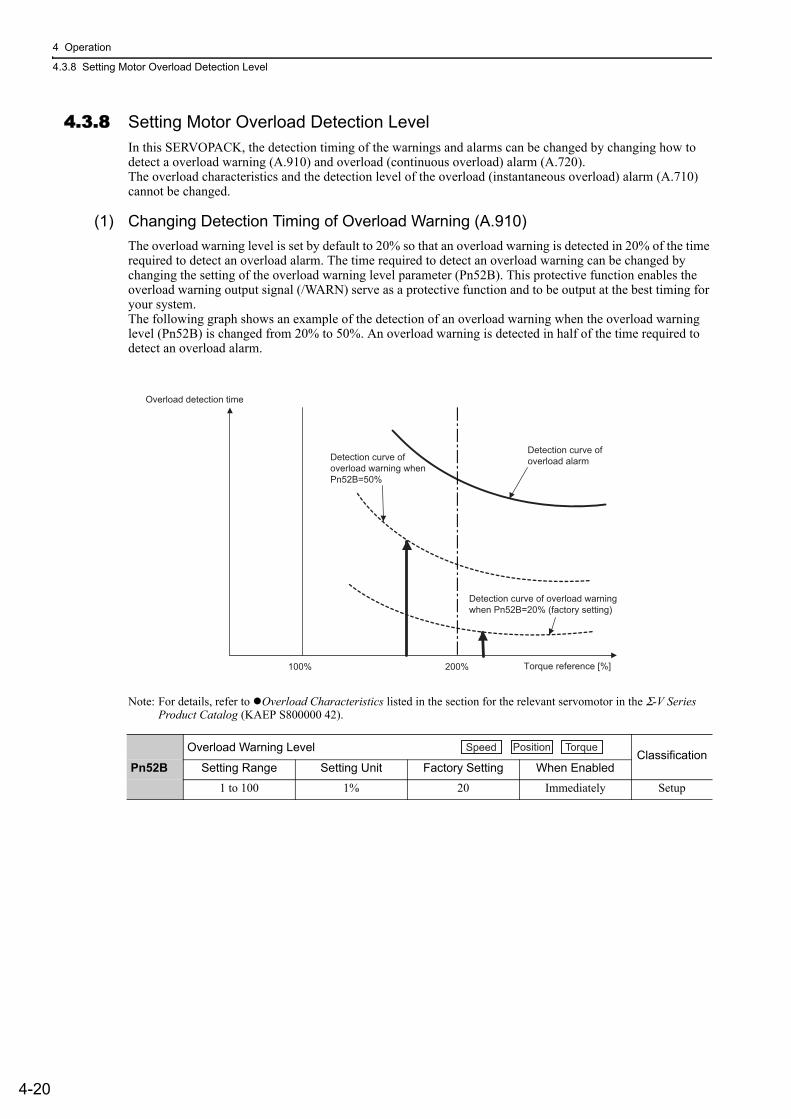
4 Operation
4.3.8 Setting Motor Overload Detection Level
4-20
4.3.8 Setting Motor Overload Detection LevelIn this SERVOPACK, the detection timing of the warnings and alarms can be changed by changing how to detect a overload warning (A.910) and overload (continuous overload) alarm (A.720).The overload characteristics and the detection level of the overload (instantaneous overload) alarm (A.710) cannot be changed.
(1) Changing Detection Timing of Overload Warning (A.910)The overload warning level is set by default to 20% so that an overload warning is detected in 20% of the time required to detect an overload alarm. The time required to detect an overload warning can be changed by changing the setting of the overload warning level parameter (Pn52B). This protective function enables the overload warning output signal (/WARN) serve as a protective function and to be output at the best timing for your system.The following graph shows an example of the detection of an overload warning when the overload warning level (Pn52B) is changed from 20% to 50%. An overload warning is detected in half of the time required to detect an overload alarm.
Note: For details, refer to Overload Characteristics listed in the section for the relevant servomotor in the Σ-V Series Product Catalog (KAEP S800000 42).
Overload Warning Level Classification
Pn52B Setting Range Setting Unit Factory Setting When Enabled
1 to 100 1% 20 Immediately Setup
200%100%
Overload detection time
Detection curve ofoverload alarm
Detection curve of overload warning when Pn52B=20% (factory setting)
Detection curve of overload warning whenPn52B=50%
Torque reference [%]
Speed Position Torque
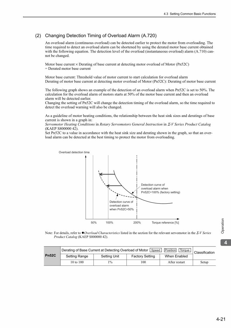
4.3 Setting Common Basic Functions
4-21
4
Op
era
tio
n
(2) Changing Detection Timing of Overload Alarm (A.720)An overload alarm (continuous overload) can be detected earlier to protect the motor from overloading. The time required to detect an overload alarm can be shortened by using the derated motor base current obtained with the following equation. The detection level of the overload (instantaneous overload) alarm (A.710) can-not be changed.
Motor base current × Derating of base current at detecting motor overload of Motor (Pn52C) = Derated motor base current
Motor base current: Threshold value of motor current to start calculation for overload alarmDerating of motor base current at detecting motor overload of Motor (Pn52C): Derating of motor base current
The following graph shows an example of the detection of an overload alarm when Pn52C is set to 50%. The calculation for the overload alarm of motors starts at 50% of the motor base current and then an overload alarm will be detected earlier.Changing the setting of Pn52C will change the detection timing of the overload alarm, so the time required to detect the overload warning will also be changed.
As a guideline of motor heating conditions, the relationship between the heat sink sizes and deratings of base current is shown in a graph in:Servomotor Heating Conditions in Rotary Servomotors General Instruction in Σ-V Series Product Catalog (KAEP S800000 42).Set Pn52C to a value in accordance with the heat sink size and derating shown in the graph, so that an over-load alarm can be detected at the best timing to protect the motor from overloading.
Note: For details, refer to Overload Characteristics listed in the section for the relevant servomotor in the Σ-V Series Product Catalog (KAEP S800000 42).
Pn52CDerating of Base Current at Detecting Overload of Motor
ClassificationSetting Range Setting Unit Factory Setting When Enabled
10 to 100 1% 100 After restart Setup
Detection curve of overload alarm when Pn52C=100% (factory setting)
Detection curve of overload alarmwhen Pn52C=50%
Torque reference [%]50%
Overload detection time
100% 200%
Speed Position Torque
4 Operation
4.4.1 Inspection and Checking before Trial Operation
4-22
4.4 Trial OperationThis section describes a trial operation using MECHATROLINK-II communications.
4.4.1 Inspection and Checking before Trial OperationTo ensure safe and correct trial operation, inspect and check the following items before starting trial operation.
(1) ServomotorsInspect and check the following items, and take appropriate measures before performing trial operation if any problem exists.
• Are all wiring and connections correct?• Are all nuts and bolts securely tightened?• If the servomotor has an oil seal, is the seal undamaged and is the motor oiled?
Note: When performing trial operation on a servomotor that has been stored for a long period of time, perform the inspec-tion according to the procedures described in 1.7 Inspection and Maintenance.
(2) SERVOPACKsInspect and check the following items, and take appropriate measures before performing trial operation if any problem exists.
• Are all wiring and connections correct?• Is the correct power supply voltage being supplied to the SERVOPACK?
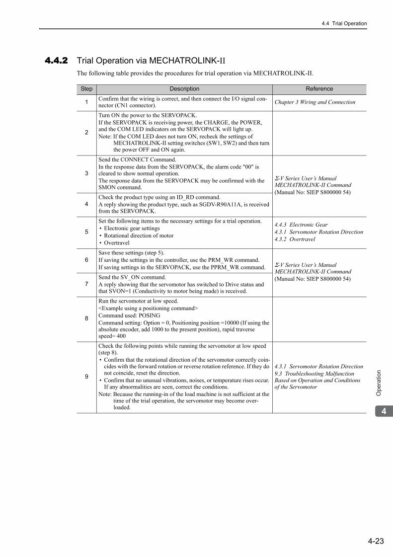
4.4 Trial Operation
4-23
4
Op
era
tio
n
4.4.2 Trial Operation via MECHATROLINK-II The following table provides the procedures for trial operation via MECHATROLINK-II.
Step Description Reference
1 Confirm that the wiring is correct, and then connect the I/O signal con-nector (CN1 connector). Chapter 3 Wiring and Connection
2
Turn ON the power to the SERVOPACK.If the SERVOPACK is receiving power, the CHARGE, the POWER, and the COM LED indicators on the SERVOPACK will light up. Note: If the COM LED does not turn ON, recheck the settings of
MECHATROLINK-II setting switches (SW1, SW2) and then turn the power OFF and ON again.
3
Send the CONNECT Command. In the response data from the SERVOPACK, the alarm code "00" is cleared to show normal operation. The response data from the SERVOPACK may be confirmed with the SMON command.
Σ-V Series User’s Manual MECHATROLINK-II Command(Manual No: SIEP S800000 54)
4Check the product type using an ID_RD command.A reply showing the product type, such as SGDV-R90A11A, is received from the SERVOPACK.
5
Set the following items to the necessary settings for a trial operation. • Electronic gear settings • Rotational direction of motor • Overtravel
4.4.3 Electronic Gear4.3.1 Servomotor Rotation Direction4.3.2 Overtravel
6Save these settings (step 5).If saving the settings in the controller, use the PRM_WR command.If saving settings in the SERVOPACK, use the PPRM_WR command. Σ-V Series User’s Manual
MECHATROLINK-II Command (Manual No: SIEP S800000 54)
7Send the SV_ON command. A reply showing that the servomotor has switched to Drive status and that SVON=1 (Conductivity to motor being made) is received.
8
Run the servomotor at low speed. <Example using a positioning command>Command used: POSINGCommand setting: Option = 0, Positioning position =10000 (If using the absolute encoder, add 1000 to the present position), rapid traverse speed= 400
9
Check the following points while running the servomotor at low speed (step 8). • Confirm that the rotational direction of the servomotor correctly coin-
cides with the forward rotation or reverse rotation reference. If they do not coincide, reset the direction.
• Confirm that no unusual vibrations, noises, or temperature rises occur. If any abnormalities are seen, correct the conditions.
Note: Because the running-in of the load machine is not sufficient at the time of the trial operation, the servomotor may become over-loaded.
4.3.1 Servomotor Rotation Direction9.3 Troubleshooting Malfunction Based on Operation and Conditions of the Servomotor
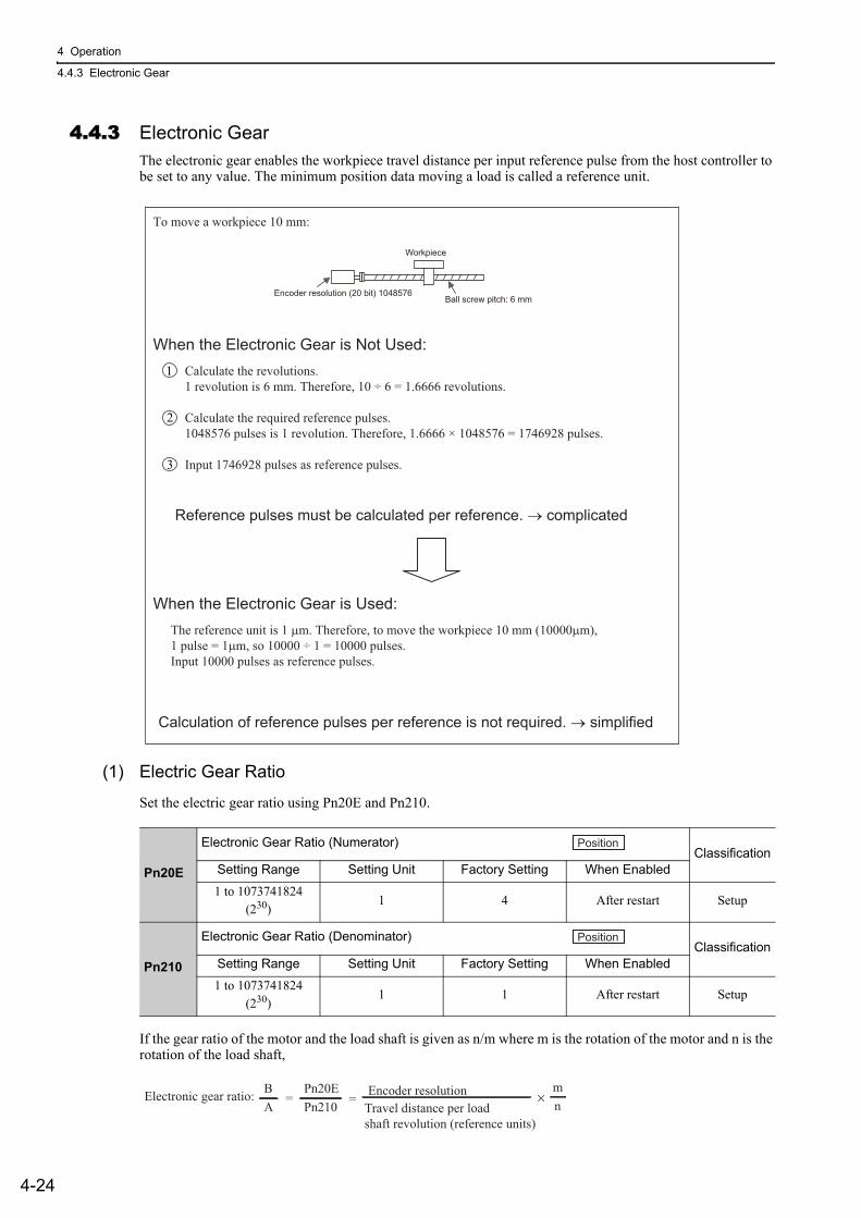
4 Operation
4.4.3 Electronic Gear
4-24
4.4.3 Electronic GearThe electronic gear enables the workpiece travel distance per input reference pulse from the host controller to be set to any value. The minimum position data moving a load is called a reference unit.
(1) Electric Gear Ratio
Set the electric gear ratio using Pn20E and Pn210.
If the gear ratio of the motor and the load shaft is given as n/m where m is the rotation of the motor and n is the rotation of the load shaft,
To move a workpiece 10 mm:
When the Electronic Gear is Not Used: Calculate the revolutions.1 revolution is 6 mm. Therefore, 10 ÷ 6 = 1.6666 revolutions.
Calculate the required reference pulses.1048576 pulses is 1 revolution. Therefore, 1.6666 × 1048576 = 1746928 pulses.
Input 1746928 pulses as reference pulses.
Reference pulses must be calculated per reference. → complicated
When the Electronic Gear is Used:The reference unit is 1 μm. Therefore, to move the workpiece 10 mm (10000μm),1 pulse = 1μm, so 10000 ÷ 1 = 10000 pulses.Input 10000 pulses as reference pulses.
Calculation of reference pulses per reference is not required. → simplified
Ball screw pitch: 6 mm
Workpiece
Encoder resolution (20 bit) 1048576
1
2
3
Pn20E
Electronic Gear Ratio (Numerator)Classification
Setting Range Setting Unit Factory Setting When Enabled
1 to 1073741824 (230)
1 4 After restart Setup
Pn210
Electronic Gear Ratio (Denominator)Classification
Setting Range Setting Unit Factory Setting When Enabled
1 to 1073741824 (230)
1 1 After restart Setup
Position
Position
Electronic gear ratio: =AB
Pn210Pn20E
= nmEncoder resolution
Travel distance per loadshaft revolution (reference units)
×
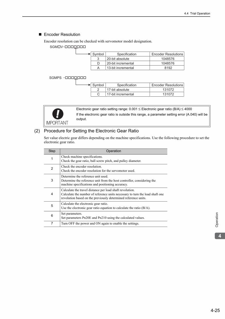
4.4 Trial Operation
4-25
4
Op
era
tio
n
Encoder ResolutionEncoder resolution can be checked with servomotor model designation.
(2) Procedure for Setting the Electronic Gear RatioSet value electric gear differs depending on the machine specifications. Use the following procedure to set the electronic gear ratio.
Electronic gear ratio setting range: 0.001 ≤ Electronic gear ratio (B/A) ≤ 4000If the electronic gear ratio is outside this range, a parameter setting error (A.040) will be output.
SGM�V �������
Symbol Specification Encoder Resolutions
Symbol Specification Encoder Resolutions
3 20-bit absolute 1048576 D 20-bit incremental 1048576 A 13-bit incremental 8192
SGMPS �������
2 17-bit absolute 131072 C 17-bit incremental 131072
Step Operation
1 Check machine specifications.Check the gear ratio, ball screw pitch, and pulley diameter.
2 Check the encoder resolution.Check the encoder resolution for the servomotor used.
3Determine the reference unit used.Determine the reference unit from the host controller, considering the machine specifications and positioning accuracy.
4Calculate the travel distance per load shaft revolution.Calculate the number of reference units necessary to turn the load shaft one revolution based on the previously determined reference units.
5 Calculate the electronic gear ratio.Use the electronic gear ratio equation to calculate the ratio (B/A).
6 Set parameters.Set parameters Pn20E and Pn210 using the calculated values.
7 Turn OFF the power and ON again to enable the settings.
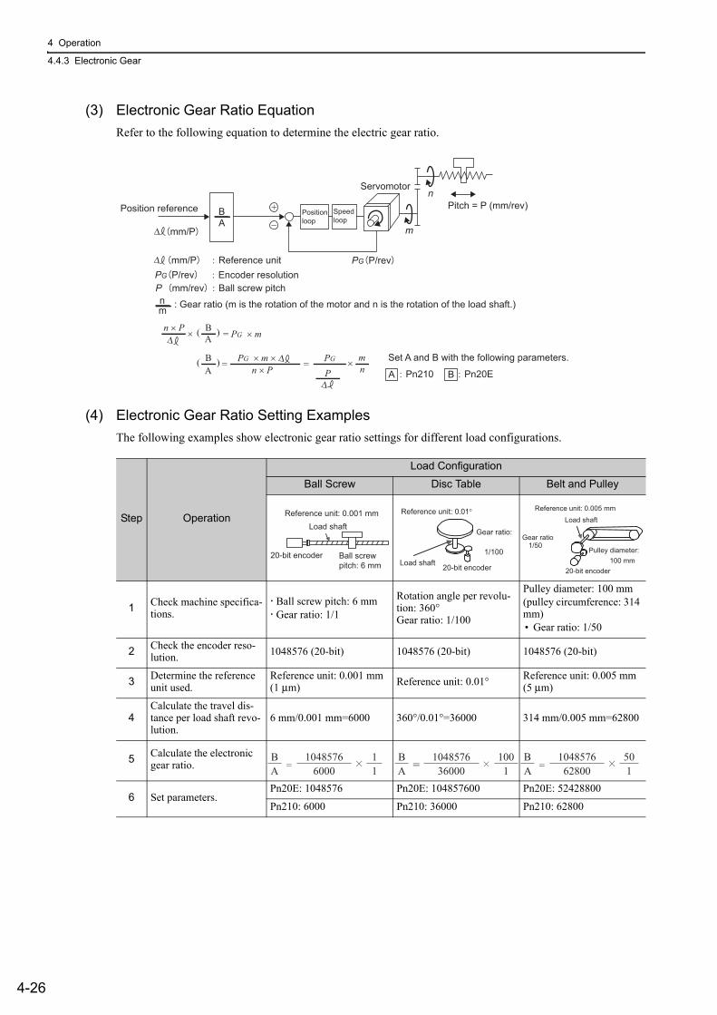
4 Operation
4.4.3 Electronic Gear
4-26
(3) Electronic Gear Ratio EquationRefer to the following equation to determine the electric gear ratio.
(4) Electronic Gear Ratio Setting ExamplesThe following examples show electronic gear ratio settings for different load configurations.
AB
nm
+
−
Pitch = P (mm/rev)
m
nServomotor
PG P/revPG P/rev Encoder resolution
Positionloop
Speedloop
Position reference
Δ
n × P
n × P
BΔ A
Δ
PΔ
Δ
×
×
( )
mn
= PG × m
BA
( ) = =PG × m × PG Set A and B with the following parameters.
A Pn20EBPn210
P mm/rev Ball screw pitch
: Gear ratio (m is the rotation of the motor and n is the rotation of the load shaft.)
mm/P Reference unit
mm/P
Step Operation
Load Configuration
Ball Screw Disc Table Belt and Pulley
1 Check machine specifica-tions.
Ball screw pitch: 6 mm Gear ratio: 1/1
Rotation angle per revolu-tion: 360°Gear ratio: 1/100
Pulley diameter: 100 mm(pulley circumference: 314 mm)• Gear ratio: 1/50
2 Check the encoder reso-lution. 1048576 (20-bit) 1048576 (20-bit) 1048576 (20-bit)
3 Determine the reference unit used.
Reference unit: 0.001 mm (1 μm) Reference unit: 0.01° Reference unit: 0.005 mm
(5 μm)
4Calculate the travel dis-tance per load shaft revo-lution.
6 mm/0.001 mm=6000 360°/0.01°=36000 314 mm/0.005 mm=62800
5 Calculate the electronic gear ratio.
6 Set parameters.Pn20E: 1048576 Pn20E: 104857600 Pn20E: 52428800
Pn210: 6000 Pn210: 36000 Pn210: 62800
Ball screw pitch: 6 mm
20-bit encoder
Load shaftReference unit: 0.001 mm
20-bit encoderLoad shaft
Reference unit: 0.01°
Gear ratio:
1/100
Load shaft
Gear ratio1/50
Reference unit: 0.005 mm
Pulley diameter:100 mm
20-bit encoder
10485766000
11=
BA
BA
104857636000
1001=
BA
104857662800
501=
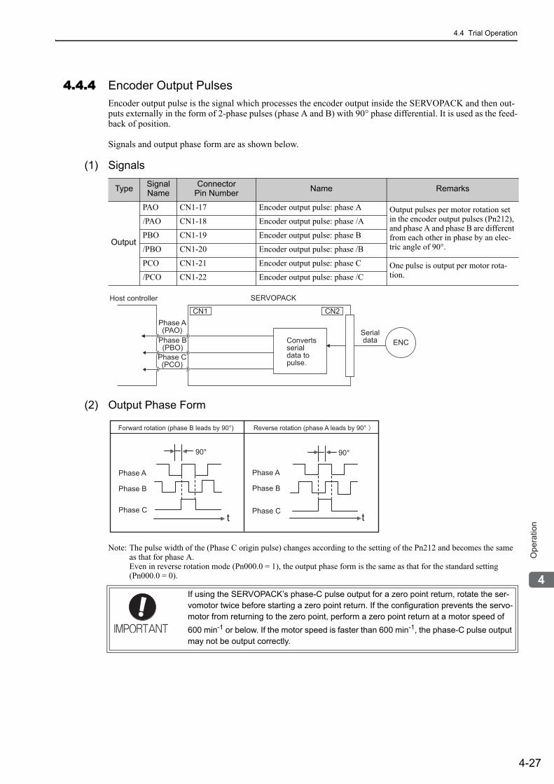
4.4 Trial Operation
4-27
4
Op
era
tio
n
4.4.4 Encoder Output PulsesEncoder output pulse is the signal which processes the encoder output inside the SERVOPACK and then out-puts externally in the form of 2-phase pulses (phase A and B) with 90° phase differential. It is used as the feed-back of position.
Signals and output phase form are as shown below.
(1) Signals
(2) Output Phase Form
Note: The pulse width of the (Phase C origin pulse) changes according to the setting of the Pn212 and becomes the same as that for phase A.Even in reverse rotation mode (Pn000.0 = 1), the output phase form is the same as that for the standard setting (Pn000.0 = 0).
Type Signal Name
Connector Pin Number Name Remarks
Output
PAO CN1-17 Encoder output pulse: phase A Output pulses per motor rotation set in the encoder output pulses (Pn212), and phase A and phase B are different from each other in phase by an elec-tric angle of 90°.
/PAO CN1-18 Encoder output pulse: phase /A
PBO CN1-19 Encoder output pulse: phase B
/PBO CN1-20 Encoder output pulse: phase /B
PCO CN1-21 Encoder output pulse: phase C One pulse is output per motor rota-tion./PCO CN1-22 Encoder output pulse: phase /C
SERVOPACKHost controller
Serialdata ENC
CN1
Convertsserialdata topulse.
CN2Phase A(PAO)
Phase B(PBO)
Phase C(PCO)
If using the SERVOPACK’s phase-C pulse output for a zero point return, rotate the ser-vomotor twice before starting a zero point return. If the configuration prevents the servo-motor from returning to the zero point, perform a zero point return at a motor speed of 600 min-1 or below. If the motor speed is faster than 600 min-1, the phase-C pulse output may not be output correctly.
Phase A
Phase B
Phase C
90°
t
Phase A
Phase B
Phase Ct
Forward rotation (phase B leads by 90°) Reverse rotation (phase A leads by 90°
90°
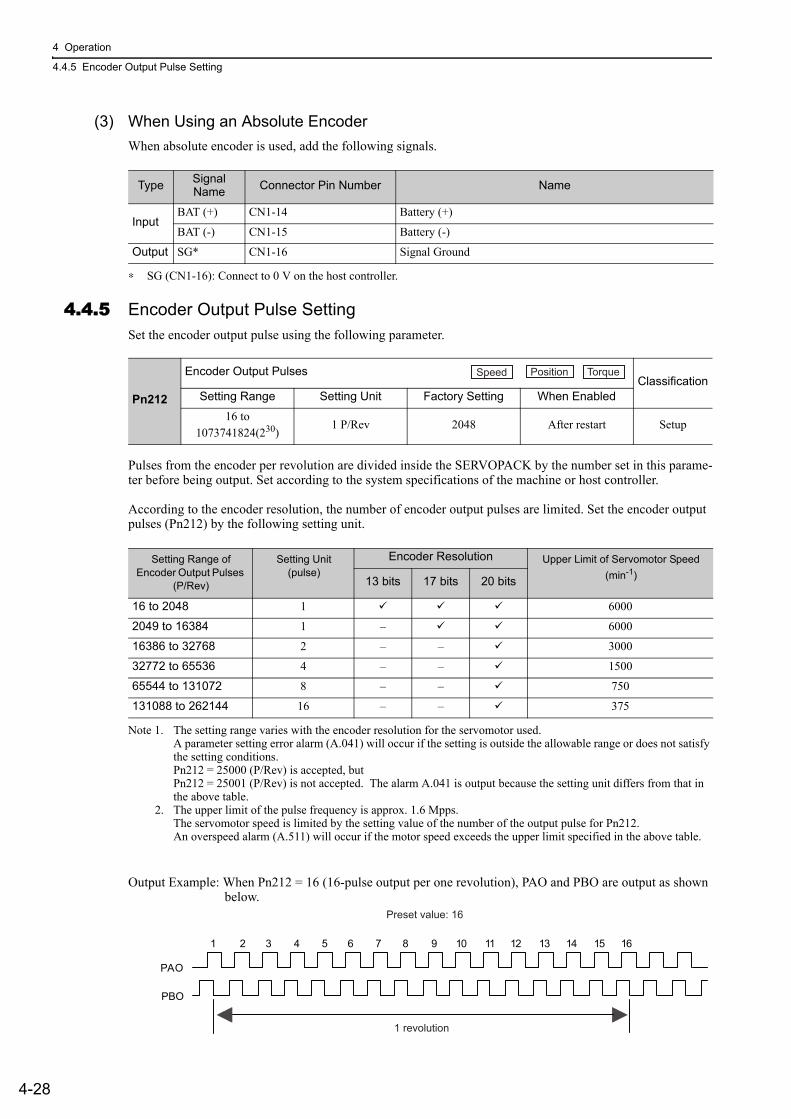
4 Operation
4.4.5 Encoder Output Pulse Setting
4-28
(3) When Using an Absolute EncoderWhen absolute encoder is used, add the following signals.
∗ SG (CN1-16): Connect to 0 V on the host controller.
4.4.5 Encoder Output Pulse SettingSet the encoder output pulse using the following parameter.
Pulses from the encoder per revolution are divided inside the SERVOPACK by the number set in this parame-ter before being output. Set according to the system specifications of the machine or host controller.
According to the encoder resolution, the number of encoder output pulses are limited. Set the encoder output pulses (Pn212) by the following setting unit.
Note 1. The setting range varies with the encoder resolution for the servomotor used.A parameter setting error alarm (A.041) will occur if the setting is outside the allowable range or does not satisfy the setting conditions.Pn212 = 25000 (P/Rev) is accepted, butPn212 = 25001 (P/Rev) is not accepted. The alarm A.041 is output because the setting unit differs from that in the above table.
2. The upper limit of the pulse frequency is approx. 1.6 Mpps.The servomotor speed is limited by the setting value of the number of the output pulse for Pn212.An overspeed alarm (A.511) will occur if the motor speed exceeds the upper limit specified in the above table.
Output Example: When Pn212 = 16 (16-pulse output per one revolution), PAO and PBO are output as shown below.
Type Signal Name Connector Pin Number Name
InputBAT (+) CN1-14 Battery (+)
BAT (-) CN1-15 Battery (-)
Output SG* CN1-16 Signal Ground
Pn212
Encoder Output PulsesClassification
Setting Range Setting Unit Factory Setting When Enabled
16 to 1073741824(230)
1 P/Rev 2048 After restart Setup
Speed Position Torque
Setting Range of Encoder Output Pulses
(P/Rev)
Setting Unit (pulse)
Encoder Resolution Upper Limit of Servomotor Speed(min-1)13 bits 17 bits 20 bits
16 to 2048 1 6000
2049 to 16384 1 – 6000
16386 to 32768 2 – – 3000
32772 to 65536 4 – – 1500
65544 to 131072 8 – – 750
131088 to 262144 16 – – 375
Preset value: 16
1 revolution
PAO
PBO
1 2 3 4 5 6 7 8 9 10 11 12 13 14 15 16
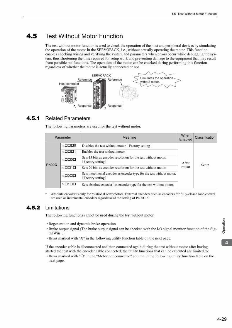
4.5 Test Without Motor Function
4-29
4
Op
era
tio
n
4.5 Test Without Motor FunctionThe test without motor function is used to check the operation of the host and peripheral devices by simulating the operation of the motor in the SERVOPACK, i.e., without actually operating the motor. This function enables checking wiring and verifying the system and parameters when errors occur while debugging the sys-tem, thus shortening the time required for setup work and preventing damage to the equipment that may result from possible malfunctions. The operation of the motor can be checked during performing this function regardless of whether the motor is actually connected or not.
4.5.1 Related ParametersThe following parameters are used for the test without motor.
∗ Absolute encoder is only for rotational servomotors. External encoders such as encoders for fully-closed loop control are used as incremental encoders regardless of the setting of Pn00C.2.
4.5.2 LimitationsThe following functions cannot be used during the test without motor.
• Regeneration and dynamic brake operation• Brake output signal (The brake output signal can be checked with the I/O signal monitor function of the Sig-
maWin+.)• Items marked with "X" in the following utility function table on the next page.
If the encoder cable is disconnected and then connected again during the test without motor after having started the test with the encoder cable connected, the utility functions that can be executed are limited to:• Items marked with " " in the "Motor not connected" column in the following utility function table on the
next page.
Reference Reference
ResponseResponse
Host controller
SERVOPACKSimulates the operation without motor.
Parameter Meaning When Enabled Classification
Pn00C
n. 0 Disables the test without motor. [Factory setting]
After restart Setup
n. 1 Enables the test without motor.
n. 0 Sets 13 bits as encoder resolution for the test without motor. [Factory setting]
n. 1 Sets 20 bits as encoder resolution for the test without motor.
n. 0 Sets incremental encoder as encoder type for the test without motor. [Factory setting]
n. 1 Sets absolute encoder* as encoder type for the test without motor.
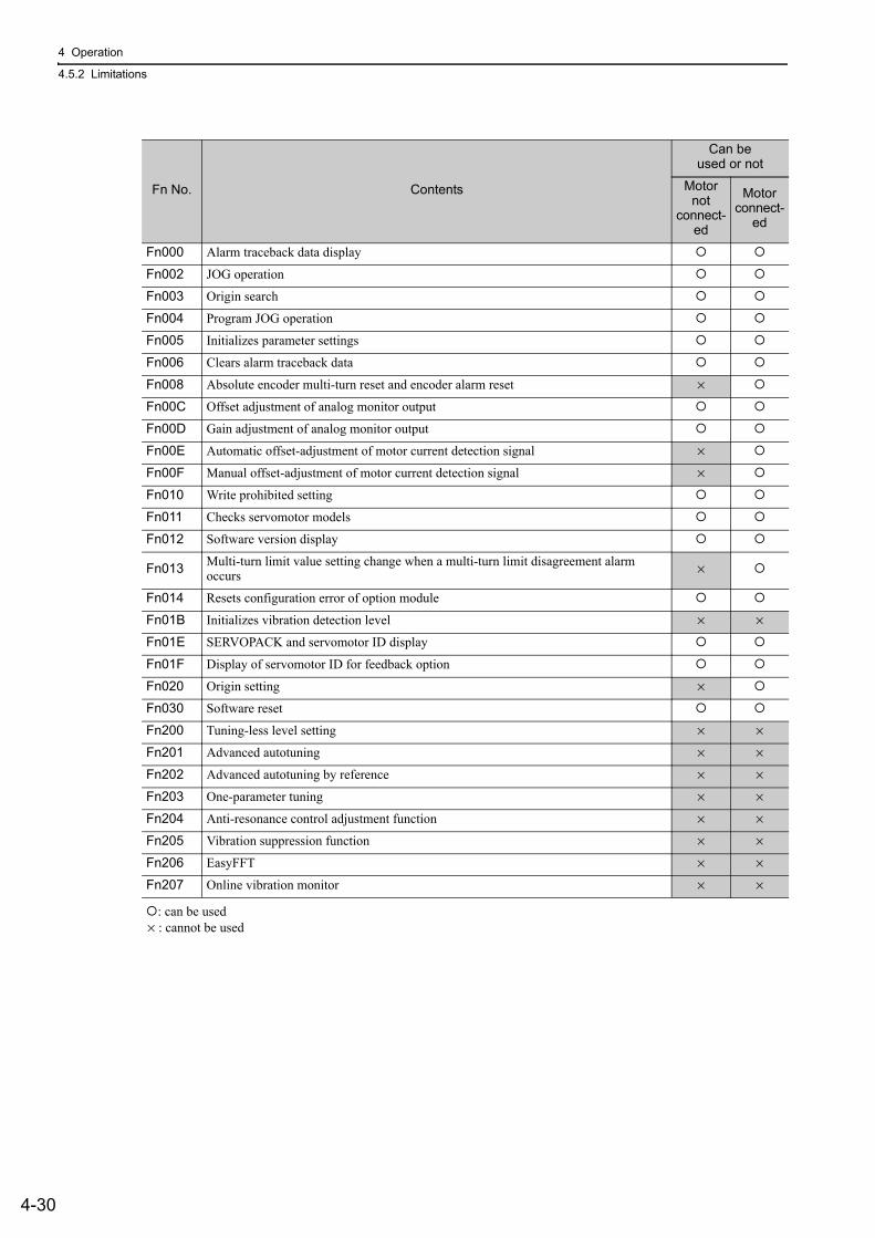
4 Operation
4.5.2 Limitations
4-30
: can be used × : cannot be used
Fn No. Contents
Can be used or not
Motor not
connect-ed
Motor connect-
ed
Fn000 Alarm traceback data display
Fn002 JOG operation
Fn003 Origin search
Fn004 Program JOG operation
Fn005 Initializes parameter settings
Fn006 Clears alarm traceback data
Fn008 Absolute encoder multi-turn reset and encoder alarm reset ×
Fn00C Offset adjustment of analog monitor output
Fn00D Gain adjustment of analog monitor output
Fn00E Automatic offset-adjustment of motor current detection signal ×
Fn00F Manual offset-adjustment of motor current detection signal ×
Fn010 Write prohibited setting
Fn011 Checks servomotor models
Fn012 Software version display
Fn013 Multi-turn limit value setting change when a multi-turn limit disagreement alarm occurs ×
Fn014 Resets configuration error of option module
Fn01B Initializes vibration detection level × ×
Fn01E SERVOPACK and servomotor ID display
Fn01F Display of servomotor ID for feedback option
Fn020 Origin setting ×
Fn030 Software reset
Fn200 Tuning-less level setting × ×
Fn201 Advanced autotuning × ×
Fn202 Advanced autotuning by reference × ×
Fn203 One-parameter tuning × ×
Fn204 Anti-resonance control adjustment function × ×
Fn205 Vibration suppression function × ×
Fn206 EasyFFT × ×
Fn207 Online vibration monitor × ×
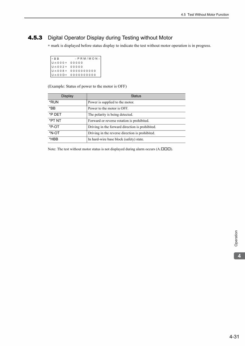
4.5 Test Without Motor Function
4-31
4
Op
era
tio
n
4.5.3 Digital Operator Display during Testing without Motor∗ mark is displayed before status display to indicate the test without motor operation is in progress.
(Example: Status of power to the motor is OFF)
Note: The test without motor status is not displayed during alarm occurs (A. ).
Display Status
*RUN Power is supplied to the motor.
*BB Power to the motor is OFF.
*P DET The polarity is being detected.
*PT NT Forward or reverse rotation is prohibited.
*P-OT Driving in the forward direction is prohibited.
*N-OT Driving in the reverse direction is prohibited.
*HBB In hard-wire base block (safety) state.
∗ B B − P R M / M O N −U n 0 0 0 = 0 0 0 0 0 0
U n 0 0 2 = 0 0 0 0 0 0
U n 0 0 8 = 0 0 0 0 0 0 0 0 0 0 0
U n 0 0 D = 0 0 0 0 0 0 0 0 0 0 0
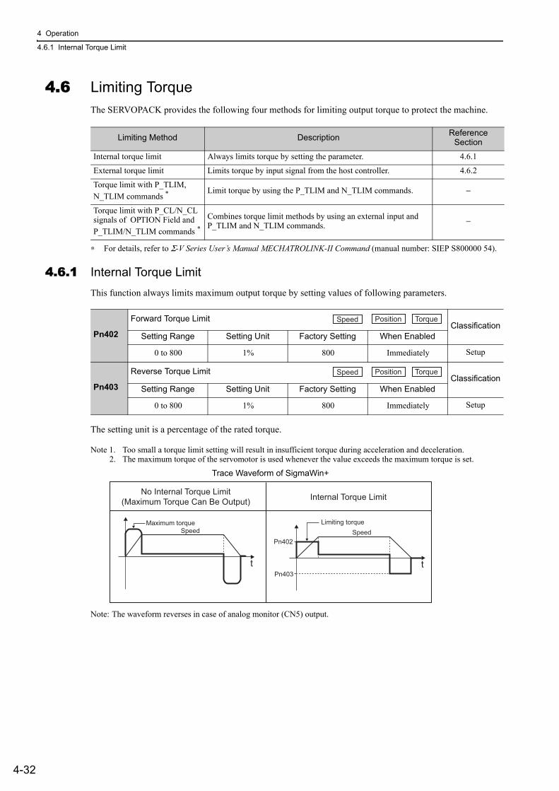
4 Operation
4.6.1 Internal Torque Limit
4-32
4.6 Limiting TorqueThe SERVOPACK provides the following four methods for limiting output torque to protect the machine.
∗ For details, refer to Σ-V Series User’s Manual MECHATROLINK-II Command (manual number: SIEP S800000 54).
4.6.1 Internal Torque LimitThis function always limits maximum output torque by setting values of following parameters.
The setting unit is a percentage of the rated torque.
Note 1. Too small a torque limit setting will result in insufficient torque during acceleration and deceleration.2. The maximum torque of the servomotor is used whenever the value exceeds the maximum torque is set.
Trace Waveform of SigmaWin+
Note: The waveform reverses in case of analog monitor (CN5) output.
Limiting Method Description Reference Section
Internal torque limit Always limits torque by setting the parameter. 4.6.1
External torque limit Limits torque by input signal from the host controller. 4.6.2
Torque limit with P_TLIM, N_TLIM commands *
Limit torque by using the P_TLIM and N_TLIM commands. −
Torque limit with P_CL/N_CL signals of OPTION Field and P_TLIM/N_TLIM commands *
Combines torque limit methods by using an external input and P_TLIM and N_TLIM commands. −
Pn402
Forward Torque LimitClassification
Setting Range Setting Unit Factory Setting When Enabled
0 to 800 1% 800 Immediately Setup
Pn403
Reverse Torque LimitClassification
Setting Range Setting Unit Factory Setting When Enabled
0 to 800 1% 800 Immediately Setup
Speed Position Torque
Speed Position Torque
SpeedMaximum torque
t
Speed
Pn403
Pn402
Limiting torque
t
No Internal Torque Limit(Maximum Torque Can Be Output) Internal Torque Limit
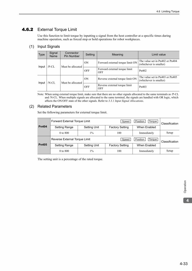
4.6 Limiting Torque
4-33
4
Op
era
tio
n
4.6.2 External Torque LimitUse this function to limit torque by inputting a signal from the host controller at a specific times during machine operation, such as forced stop or hold operations for robot workpieces.
(1) Input Signals
Note: When using external torque limit, make sure that there are no other signals allocated to the same terminals as /P-CL and /N-CL. When multiple signals are allocated to the same terminal, the signals are handled with OR logic, which affects the ON/OFF state of the other signals. Refer to 3.3.1 Input Signal Allocations.
(2) Related ParametersSet the following parameters for external torque limit.
The setting unit is a percentage of the rated torque.
Type Signal Name
ConnectorPin Number Setting Meaning Limit value
Input /P-CL Must be allocatedON Forward external torque limit ON The value set in Pn402 or Pn404
(whichever is smaller)
OFF Forward external torque limit OFF Pn402
Input /N-CL Must be allocatedON Reverse external torque limit ON The value set in Pn403 or Pn405
(whichever is smaller)
OFF Reverse external torque limit OFF Pn403
Pn404
Forward External Torque LimitClassification
Setting Range Setting Unit Factory Setting When Enabled
0 to 800 1% 100 Immediately Setup
Pn405
Reverse External Torque LimitClassification
Setting Range Setting Unit Factory Setting When Enabled
0 to 800 1% 100 Immediately Setup
Speed Position Torque
Speed Position Torque
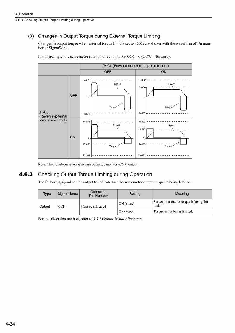
4 Operation
4.6.3 Checking Output Torque Limiting during Operation
4-34
(3) Changes in Output Torque during External Torque LimitingChanges in output torque when external torque limit is set to 800% are shown with the waveform of Un mon-itor or SigmaWin+.
In this example, the servomotor rotation direction is Pn000.0 = 0 (CCW = forward).
Note: The waveform reverses in case of analog monitor (CN5) output.
4.6.3 Checking Output Torque Limiting during OperationThe following signal can be output to indicate that the servomotor output torque is being limited.
For the allocation method, refer to 3.3.2 Output Signal Allocation.
/P-CL (Forward external torque limit input)
OFF ON
/N-CL(Reverse external torque limit input)
OFF
ON
Pn402
Pn403
0
Torque
Speed
Pn403
0
Pn404
Pn402
Torque
Speed
0
Pn403
Pn405
Pn402
Torque
Speed
0
Pn403
Pn405
Pn404
Pn402
Torque
Speed
Type Signal Name Connector Pin Number Setting Meaning
Output /CLT Must be allocatedON (close) Servomotor output torque is being lim-
ited.
OFF (open) Torque is not being limited.
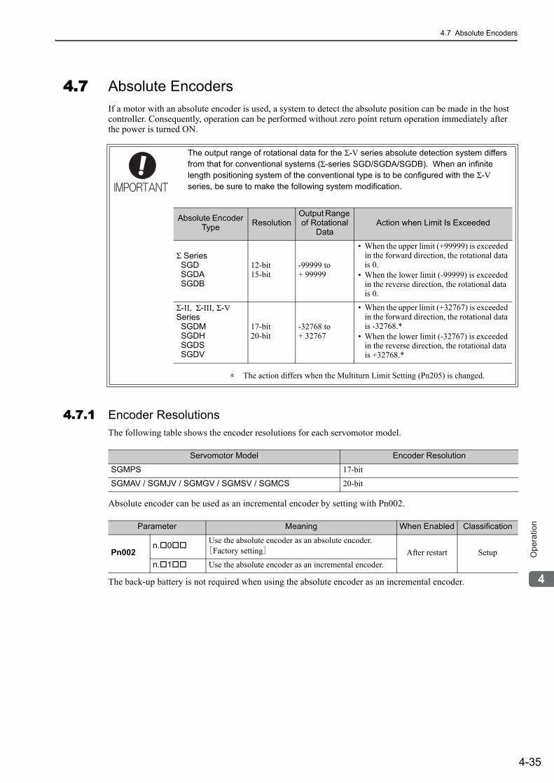
4.7 Absolute Encoders
4-35
4
Op
era
tio
n
4.7 Absolute EncodersIf a motor with an absolute encoder is used, a system to detect the absolute position can be made in the host controller. Consequently, operation can be performed without zero point return operation immediately after the power is turned ON.
4.7.1 Encoder ResolutionsThe following table shows the encoder resolutions for each servomotor model.
Absolute encoder can be used as an incremental encoder by setting with Pn002.
The back-up battery is not required when using the absolute encoder as an incremental encoder.
The output range of rotational data for the Σ-V series absolute detection system differs from that for conventional systems (Σ-series SGD/SGDA/SGDB). When an infinite length positioning system of the conventional type is to be configured with the Σ-V series, be sure to make the following system modification.
∗ The action differs when the Multiturn Limit Setting (Pn205) is changed.
Absolute Encoder Type Resolution
Output Range of Rotational
DataAction when Limit Is Exceeded
Σ Series SGD SGDA SGDB
12-bit15-bit
-99999 to + 99999
• When the upper limit (+99999) is exceeded in the forward direction, the rotational data is 0.
• When the lower limit (-99999) is exceeded in the reverse direction, the rotational data is 0.
Σ-II, Σ-III, Σ-V Series SGDM SGDH SGDS SGDV
17-bit20-bit
-32768 to + 32767
• When the upper limit (+32767) is exceeded in the forward direction, the rotational data is -32768.*
• When the lower limit (-32767) is exceeded in the reverse direction, the rotational data is +32768.*
Servomotor Model Encoder Resolution
SGMPS 17-bit
SGMAV / SGMJV / SGMGV / SGMSV / SGMCS 20-bit
Parameter Meaning When Enabled Classification
Pn002n. 0 Use the absolute encoder as an absolute encoder.
[Factory setting] After restart Setupn. 1 Use the absolute encoder as an incremental encoder.
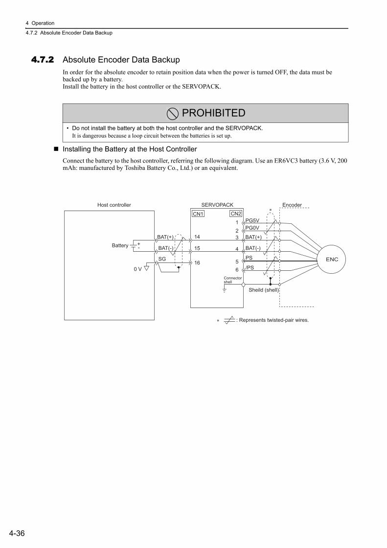
4 Operation
4.7.2 Absolute Encoder Data Backup
4-36
4.7.2 Absolute Encoder Data BackupIn order for the absolute encoder to retain position data when the power is turned OFF, the data must be backed up by a battery.Install the battery in the host controller or the SERVOPACK.
Installing the Battery at the Host ControllerConnect the battery to the host controller, referring the following diagram. Use an ER6VC3 battery (3.6 V, 200 mAh: manufactured by Toshiba Battery Co., Ltd.) or an equivalent.
PROHIBITED• Do not install the battery at both the host controller and the SERVOPACK.
It is dangerous because a loop circuit between the batteries is set up.
PG5VPG0V
BAT(+)
PS
/PS
BAT(-)
CN1123
4
65
CN2
Host controller SERVOPACK Encoder
: Represents twisted-pair wires.
Sheild (shell)
Connectorshell
ENC
∗
∗
BatteryBAT(+)
BAT(-)
SG
0 V
-
14
15
16
+
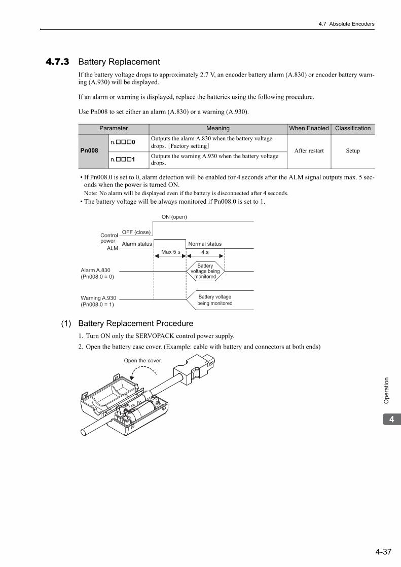
4.7 Absolute Encoders
4-37
4
Op
era
tio
n
4.7.3 Battery ReplacementIf the battery voltage drops to approximately 2.7 V, an encoder battery alarm (A.830) or encoder battery warn-ing (A.930) will be displayed.
If an alarm or warning is displayed, replace the batteries using the following procedure.
Use Pn008 to set either an alarm (A.830) or a warning (A.930).
• If Pn008.0 is set to 0, alarm detection will be enabled for 4 seconds after the ALM signal outputs max. 5 sec-onds when the power is turned ON.Note: No alarm will be displayed even if the battery is disconnected after 4 seconds.
• The battery voltage will be always monitored if Pn008.0 is set to 1.
(1) Battery Replacement Procedure1. Turn ON only the SERVOPACK control power supply.2. Open the battery case cover. (Example: cable with battery and connectors at both ends)
Parameter Meaning When Enabled Classification
Pn008n. 0 Outputs the alarm A.830 when the battery voltage
drops. [Factory setting]After restart Setup
n. 1 Outputs the warning A.930 when the battery voltage drops.
4 sMax 5 s
Warning A.930(Pn008.0 = 1)
Alarm A.830(Pn008.0 = 0)
ALM
OFF (close)
Alarm status Normal status
ON (open)
Batteryvoltage being
monitored
Battery voltagebeing monitored
Controlpower
Open the cover.
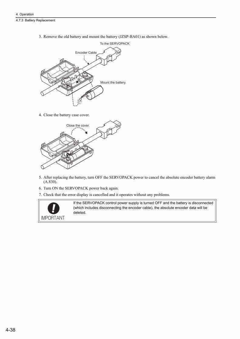
4 Operation
4.7.3 Battery Replacement
4-38
3. Remove the old battery and mount the battery (JZSP-BA01) as shown below.
4. Close the battery case cover.
5. After replacing the battery, turn OFF the SERVOPACK power to cancel the absolute encoder battery alarm (A.830).
6. Turn ON the SERVOPACK power back again.7. Check that the error display is cancelled and it operates without any problems.
If the SERVOPACK control power supply is turned OFF and the battery is disconnected (which includes disconnecting the encoder cable), the absolute encoder data will be deleted.
Mount the battery.
To the SERVOPACK
Encoder Cable
Close the cover.
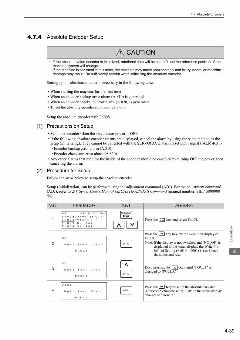
4.7 Absolute Encoders
4-39
4
Op
era
tio
n
4.7.4 Absolute Encoder Setup
Setting up the absolute encoder is necessary in the following cases.
• When starting the machine for the first time• When an encoder backup error alarm (A.810) is generated • When an encoder checksum error alarm (A.820) is generated• To set the absolute encoder rotational data to 0
Setup the absolute encoder with Fn008.
(1) Precautions on Setup• Setup the encoder when the servomotor power is OFF.• If the following absolute encoder alarms are displayed, cancel the alarm by using the same method as the
setup (initializing). They cannot be canceled with the SERVOPACK alarm reset input signal (/ALM-RST).• Encoder backup error alarm (A.810)• Encoder checksum error alarm (A.820)
• Any other alarms that monitor the inside of the encoder should be canceled by turning OFF the power, then canceling the alarm.
(2) Procedure for SetupFollow the steps below to setup the absolute encoder.
Setup (Initialization) can be performed using the adjustment command (ADJ). For the adjustment command (ADJ), refer to Σ-V Series User’s Manual MECHATROLINK-II Command (manual number: SIEP S800000 54).
CAUTION• If the absolute value encoder is initialized, rotational data will be set to 0 and the reference position of the
machine system will change.If the machine is operated in this state, the machine may move unexpectedly and injury, death, or machine damage may result. Be sufficiently careful when initializing the absolute encoder.
Step Panel Display Keys Description
1 Press the key and select Fn008.
2
Press the key to view the execution display of Fn008.Note: If the display is not switched and "NO_OP" is
displayed in the status display, the Write Pro-hibited Setting (Fn010 = 0001) is set. Check the status and reset.
3 Keep pressing the Key until "PGCL1" is changed to "PGCL5."
4Press the Key to setup the absolute encoder. After completing the setup, "BB" in the status display changes to "Done."
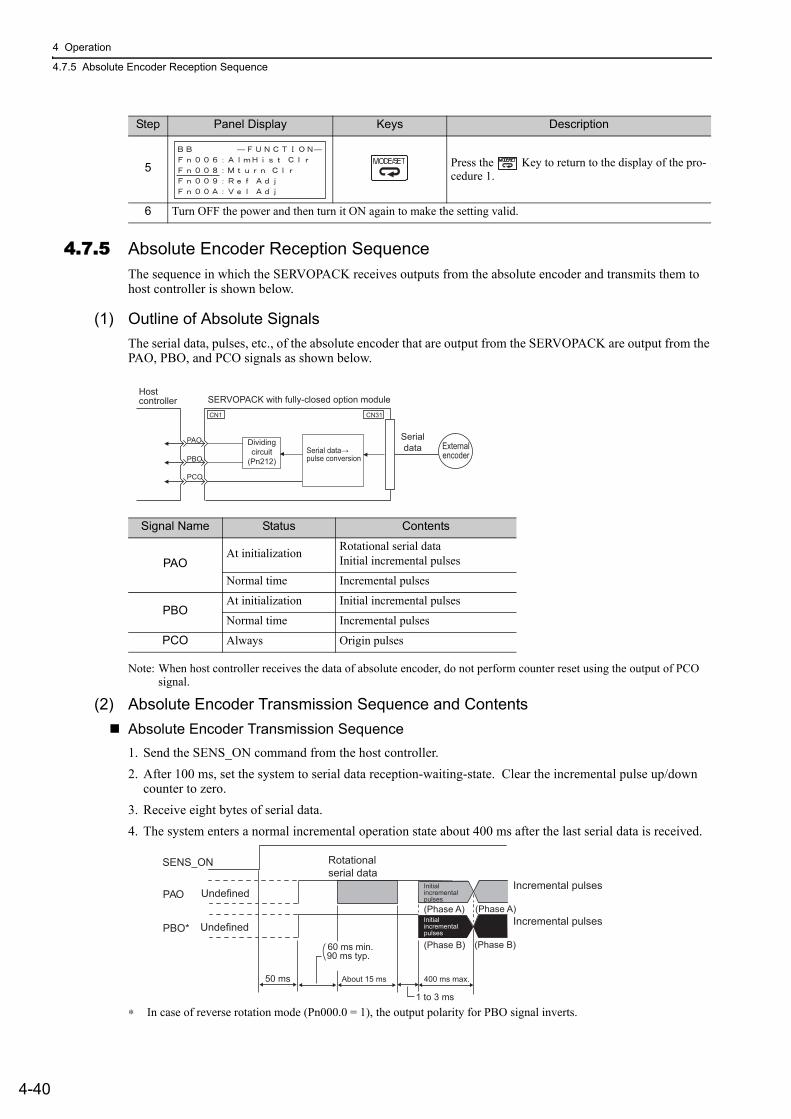
4 Operation
4.7.5 Absolute Encoder Reception Sequence
4-40
4.7.5 Absolute Encoder Reception SequenceThe sequence in which the SERVOPACK receives outputs from the absolute encoder and transmits them to host controller is shown below.
(1) Outline of Absolute SignalsThe serial data, pulses, etc., of the absolute encoder that are output from the SERVOPACK are output from the PAO, PBO, and PCO signals as shown below.
Note: When host controller receives the data of absolute encoder, do not perform counter reset using the output of PCO signal.
(2) Absolute Encoder Transmission Sequence and ContentsAbsolute Encoder Transmission Sequence1. Send the SENS_ON command from the host controller.2. After 100 ms, set the system to serial data reception-waiting-state. Clear the incremental pulse up/down
counter to zero.3. Receive eight bytes of serial data.4. The system enters a normal incremental operation state about 400 ms after the last serial data is received.
∗ In case of reverse rotation mode (Pn000.0 = 1), the output polarity for PBO signal inverts.
5 Press the Key to return to the display of the pro-cedure 1.
6 Turn OFF the power and then turn it ON again to make the setting valid.
Step Panel Display Keys Description
Signal Name Status Contents
PAOAt initialization Rotational serial data
Initial incremental pulses
Normal time Incremental pulses
PBOAt initialization Initial incremental pulses
Normal time Incremental pulses
PCO Always Origin pulses
CN31
Serialdata External
encoder
CN1
Serial data→pulse conversion
Hostcontroller SERVOPACK with fully-closed option module
PAO
PBO
PCO
Dividingcircuit
(Pn212)
SENS_ON
PAO
PBO*
Incremental pulses
Incremental pulsesUndefined
Undefined(Phase A) (Phase A)
(Phase B) (Phase B)
Rotationalserial data
400 ms max.50 ms
1 to 3 ms
About 15 ms
90 ms typ.60 ms min.
Initialincremental pulses
Initialincremental pulses
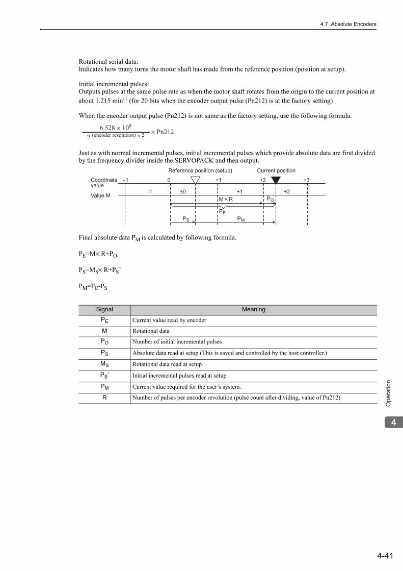
4.7 Absolute Encoders
4-41
4
Op
era
tio
n
Rotational serial data:Indicates how many turns the motor shaft has made from the reference position (position at setup).
Initial incremental pulses: Outputs pulses at the same pulse rate as when the motor shaft rotates from the origin to the current position at about 1.215 min-1 (for 20 bits when the encoder output pulse (Pn212) is at the factory setting)
When the encoder output pulse (Pn212) is not same as the factory setting, use the following formula.
Just as with normal incremental pulses, initial incremental pulses which provide absolute data are first divided by the frequency divider inside the SERVOPACK and then output.
Final absolute data PM is calculated by following formula.
PE=M× R+PO
PS=MS× R+PS’
PM=PE-PS
6.528 × 10⁸
2 (encoder resolution) × 2 × Pn212
Coordinate value
Value M
Reference position (setup)
-1 0 +1 +2 +3
+2
Current position
+1±0-1
PEPMPS
POM R
Signal Meaning
PE Current value read by encoder
M Rotational data
PO Number of initial incremental pulses
PS Absolute data read at setup (This is saved and controlled by the host controller.)
MS Rotational data read at setup
PS’ Initial incremental pulses read at setup
PM Current value required for the user’s system.
R Number of pulses per encoder revolution (pulse count after dividing, value of Pn212)
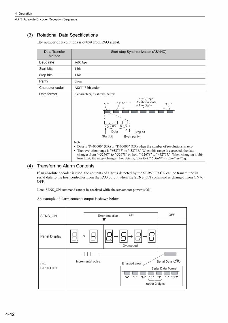
4 Operation
4.7.5 Absolute Encoder Reception Sequence
4-42
(3) Rotational Data SpecificationsThe number of revolutions is output from PAO signal.
(4) Transferring Alarm ContentsIf an absolute encoder is used, the contents of alarms detected by the SERVOPACK can be transmitted in serial data to the host controller from the PAO output when the SENS_ON command is changed from ON to OFF.
Note: SENS_ON command cannot be received while the servomotor power is ON.
An example of alarm contents output is shown below.
Data Transfer Method
Start-stop Synchronization (ASYNC)
Baud rate 9600 bps
Start bits 1 bit
Stop bits 1 bit
Parity Even
Character coder ASCII 7-bit coder
Data format 8 characters, as shown below.
Note:• Data is "P+00000" (CR) or "P-00000" (CR) when the number of revolutions is zero.• The revolution range is "+32767" to "-32768." When this range is exceeded, the data
changes from "+32767" to "-32678" or from "-32678" to "+32767." When changing multi-turn limit, the range changes. For details, refer to 4.7.6 Multiturn Limit Setting.
DataStart bit Even parity
Rotational datain five digits
"+" or " - ""0" to "9"
"CR""P"
Stop bit
0 0 0 0 0 1 0 1 0 1
OFFError detection ON
Incremental pulse CRSerial DataEnlarged view
SENS_ON
Panel Display
PAOSerial Data Serial Data Format
upper 2 digits
A L M 5 1 . CR" " " " " " " " " " " " " "
or
Overspeed
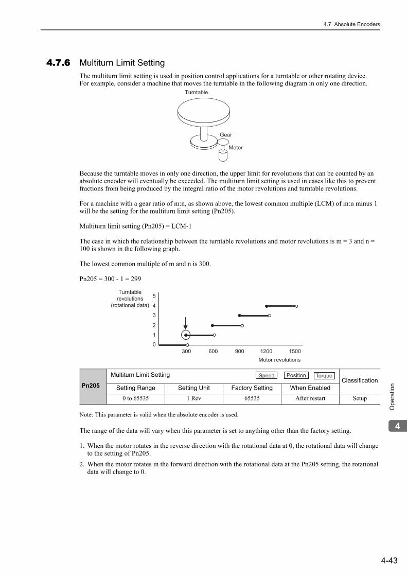
4.7 Absolute Encoders
4-43
4
Op
era
tio
n
4.7.6 Multiturn Limit SettingThe multiturn limit setting is used in position control applications for a turntable or other rotating device. For example, consider a machine that moves the turntable in the following diagram in only one direction.
Because the turntable moves in only one direction, the upper limit for revolutions that can be counted by an absolute encoder will eventually be exceeded. The multiturn limit setting is used in cases like this to prevent fractions from being produced by the integral ratio of the motor revolutions and turntable revolutions.
For a machine with a gear ratio of m:n, as shown above, the lowest common multiple (LCM) of m:n minus 1 will be the setting for the multiturn limit setting (Pn205).
Multiturn limit setting (Pn205) = LCM-1
The case in which the relationship between the turntable revolutions and motor revolutions is m = 3 and n = 100 is shown in the following graph.
The lowest common multiple of m and n is 300.
Pn205 = 300 - 1 = 299
Note: This parameter is valid when the absolute encoder is used.
The range of the data will vary when this parameter is set to anything other than the factory setting.
1. When the motor rotates in the reverse direction with the rotational data at 0, the rotational data will change to the setting of Pn205.
2. When the motor rotates in the forward direction with the rotational data at the Pn205 setting, the rotational data will change to 0.
Pn205
Multiturn Limit SettingClassification
Setting Range Setting Unit Factory Setting When Enabled
0 to 65535 1 Rev 65535 After restart Setup
Turntable
Gear
Motor
0
Turntablerevolutions
(rotational data)
1
2
3
4
5
Motor revolutions300 600 900 1200 1500
Speed Position Torque
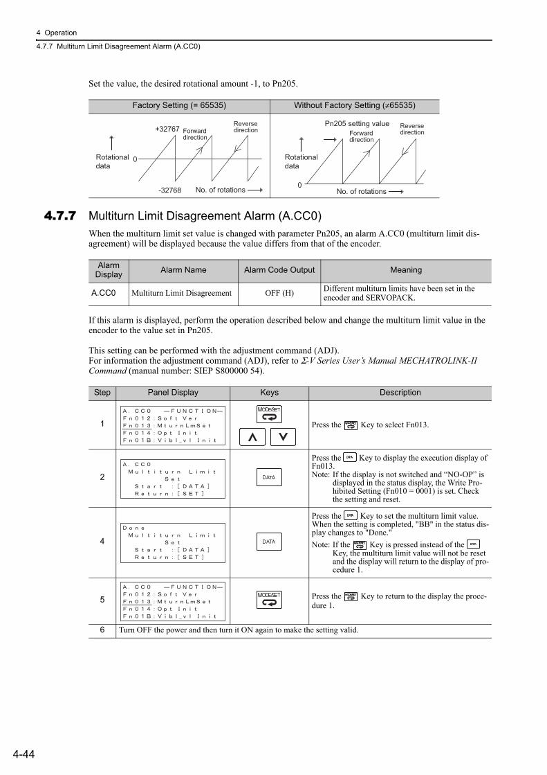
4 Operation
4.7.7 Multiturn Limit Disagreement Alarm (A.CC0)
4-44
Set the value, the desired rotational amount -1, to Pn205.
4.7.7 Multiturn Limit Disagreement Alarm (A.CC0)When the multiturn limit set value is changed with parameter Pn205, an alarm A.CC0 (multiturn limit dis-agreement) will be displayed because the value differs from that of the encoder.
If this alarm is displayed, perform the operation described below and change the multiturn limit value in theencoder to the value set in Pn205.
This setting can be performed with the adjustment command (ADJ).For information the adjustment command (ADJ), refer to Σ-V Series User’s Manual MECHATROLINK-II Command (manual number: SIEP S800000 54).
Factory Setting (= 65535) Without Factory Setting (≠65535)
+32767
-32768 No. of rotations
Rotationaldata
0
ReversedirectionForward
direction
0
Pn205 setting value Reversedirection
No. of rotations
Forwarddirection
Rotationaldata
Alarm Display Alarm Name Alarm Code Output Meaning
A.CC0 Multiturn Limit Disagreement OFF (H) Different multiturn limits have been set in the encoder and SERVOPACK.
Step Panel Display Keys Description
1 Press the Key to select Fn013.
2
Press the Key to display the execution display of Fn013.Note: If the display is not switched and “NO-OP” is
displayed in the status display, the Write Pro-hibited Setting (Fn010 = 0001) is set. Check the setting and reset.
4
Press the Key to set the multiturn limit value. When the setting is completed, "BB" in the status dis-play changes to "Done."Note: If the Key is pressed instead of the
Key, the multiturn limit value will not be reset and the display will return to the display of pro-cedure 1.
5 Press the Key to return to the display the proce-dure 1.
6 Turn OFF the power and then turn it ON again to make the setting valid.
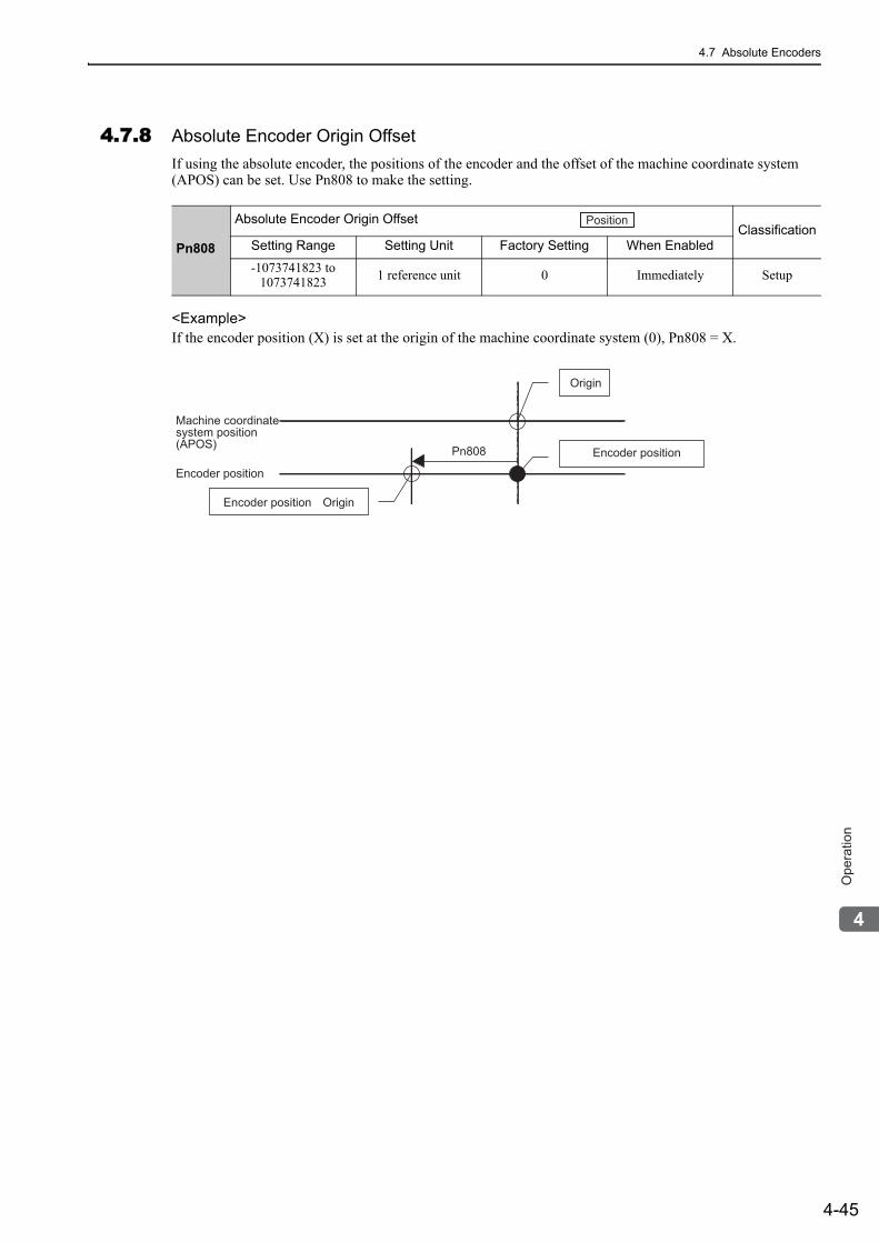
4.7 Absolute Encoders
4-45
4
Op
era
tio
n
4.7.8 Absolute Encoder Origin OffsetIf using the absolute encoder, the positions of the encoder and the offset of the machine coordinate system (APOS) can be set. Use Pn808 to make the setting.
<Example>If the encoder position (X) is set at the origin of the machine coordinate system (0), Pn808 = X.
Pn808
Absolute Encoder Origin Offset ClassificationSetting Range Setting Unit Factory Setting When Enabled
-1073741823 to 1073741823 1 reference unit 0 Immediately Setup
Position
Encoder position Origin
Origin
Machine coordinate
system position
(APOS)
Encoder position
Encoder positionPn808
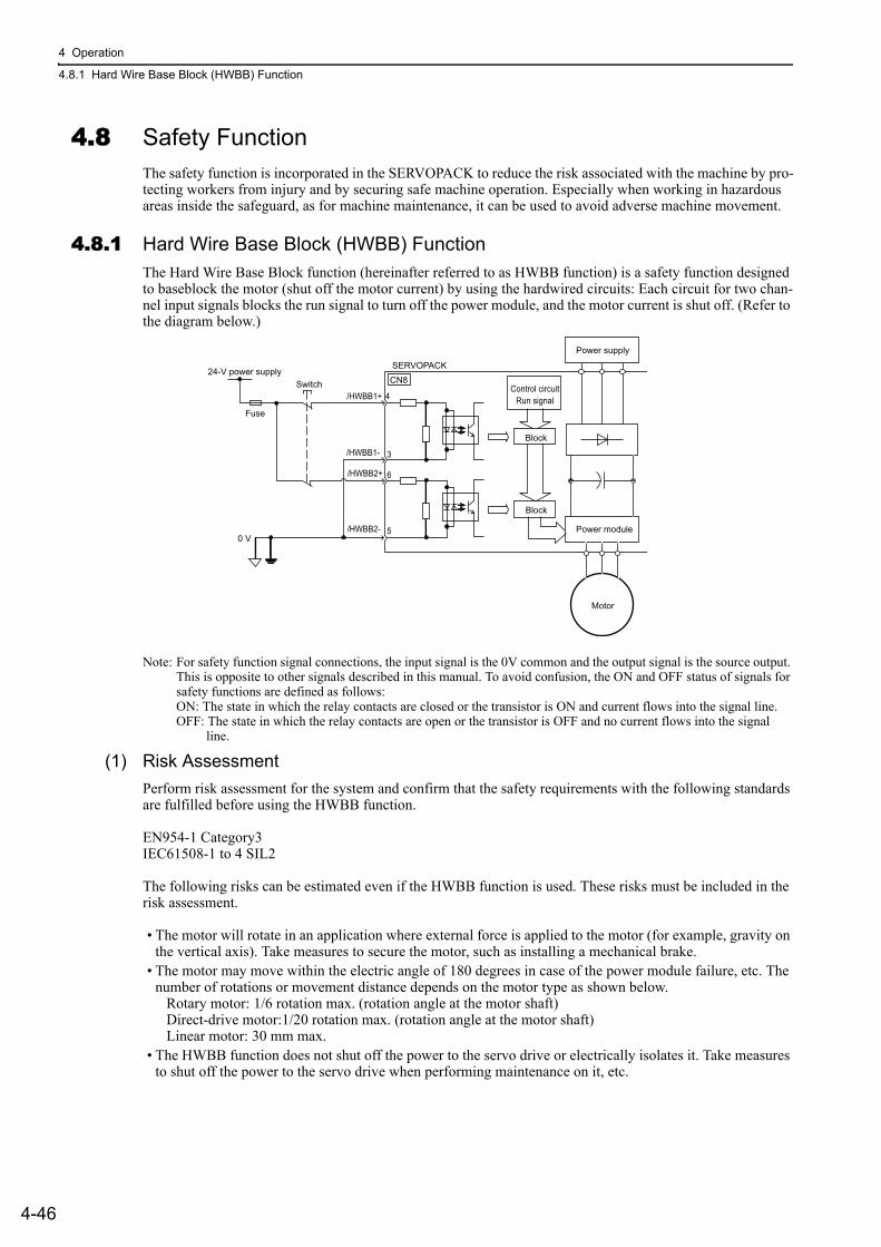
4 Operation
4.8.1 Hard Wire Base Block (HWBB) Function
4-46
4.8 Safety FunctionThe safety function is incorporated in the SERVOPACK to reduce the risk associated with the machine by pro-tecting workers from injury and by securing safe machine operation. Especially when working in hazardous areas inside the safeguard, as for machine maintenance, it can be used to avoid adverse machine movement.
4.8.1 Hard Wire Base Block (HWBB) FunctionThe Hard Wire Base Block function (hereinafter referred to as HWBB function) is a safety function designed to baseblock the motor (shut off the motor current) by using the hardwired circuits: Each circuit for two chan-nel input signals blocks the run signal to turn off the power module, and the motor current is shut off. (Refer to the diagram below.)
Note: For safety function signal connections, the input signal is the 0V common and the output signal is the source output. This is opposite to other signals described in this manual. To avoid confusion, the ON and OFF status of signals for safety functions are defined as follows:ON: The state in which the relay contacts are closed or the transistor is ON and current flows into the signal line.OFF: The state in which the relay contacts are open or the transistor is OFF and no current flows into the signal line.
(1) Risk AssessmentPerform risk assessment for the system and confirm that the safety requirements with the following standards are fulfilled before using the HWBB function.
EN954-1 Category3IEC61508-1 to 4 SIL2
The following risks can be estimated even if the HWBB function is used. These risks must be included in the risk assessment.
• The motor will rotate in an application where external force is applied to the motor (for example, gravity on the vertical axis). Take measures to secure the motor, such as installing a mechanical brake.
• The motor may move within the electric angle of 180 degrees in case of the power module failure, etc. The number of rotations or movement distance depends on the motor type as shown below. Rotary motor: 1/6 rotation max. (rotation angle at the motor shaft) Direct-drive motor:1/20 rotation max. (rotation angle at the motor shaft) Linear motor: 30 mm max.
• The HWBB function does not shut off the power to the servo drive or electrically isolates it. Take measures to shut off the power to the servo drive when performing maintenance on it, etc.
/HWBB1+ 4
3
6
5
/HWBB1-
/HWBB2+
/HWBB2-0 V
Control circuitRun signal
SERVOPACKCN8Switch
Block
Block
Power module
Power supply
24-V power supply
Fuse
Motor
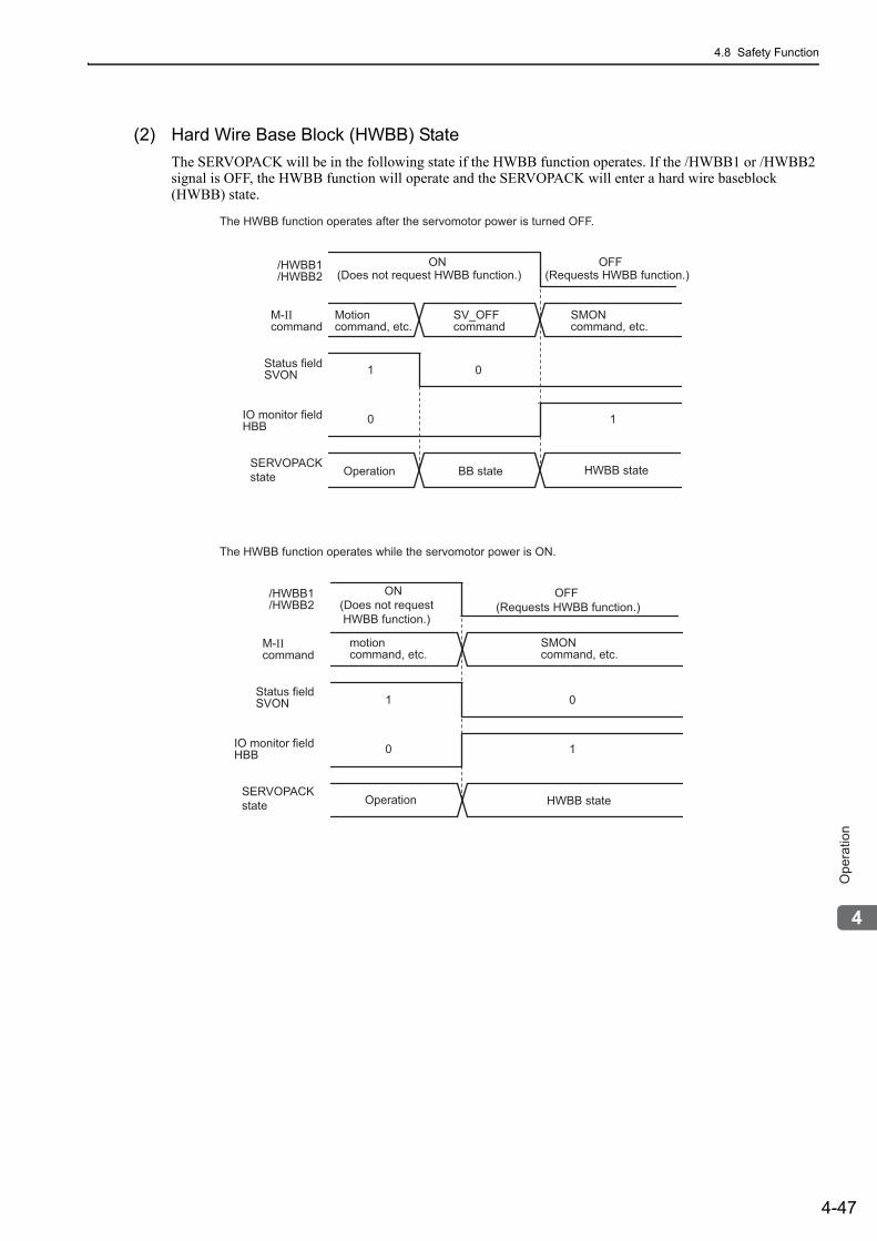
4.8 Safety Function
4-47
4
Op
era
tio
n
(2) Hard Wire Base Block (HWBB) StateThe SERVOPACK will be in the following state if the HWBB function operates. If the /HWBB1 or /HWBB2 signal is OFF, the HWBB function will operate and the SERVOPACK will enter a hard wire baseblock (HWBB) state.
/HWBB1/HWBB2
M-IIcommand
Status fieldSVON
Motioncommand, etc.
SV_OFFcommand
1 0
0 1
SMONcommand, etc.
IO monitor fieldHBB
SERVOPACKstate
ON(Does not request HWBB function.)
(Does not request HWBB function.)
OFF(Requests HWBB function.)
(Requests HWBB function.)
HWBB stateBB stateOperation
1 0
0 1
motioncommand, etc.
SMONcommand, etc.
/HWBB1/HWBB2
M-IIcommand
Status fieldSVON
IO monitor fieldHBB
SERVOPACKstate
ON OFF
HWBB stateOperation
The HWBB function operates after the servomotor power is turned OFF.
The HWBB function operates while the servomotor power is ON.
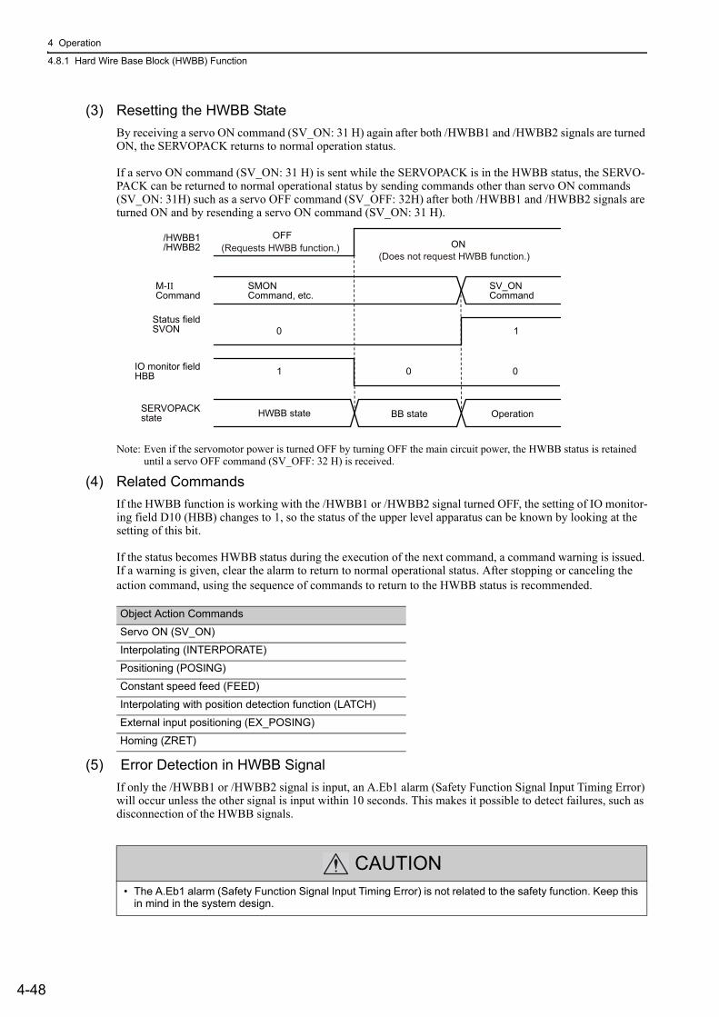
4 Operation
4.8.1 Hard Wire Base Block (HWBB) Function
4-48
(3) Resetting the HWBB StateBy receiving a servo ON command (SV_ON: 31 H) again after both /HWBB1 and /HWBB2 signals are turned ON, the SERVOPACK returns to normal operation status.
If a servo ON command (SV_ON: 31 H) is sent while the SERVOPACK is in the HWBB status, the SERVO-PACK can be returned to normal operational status by sending commands other than servo ON commands (SV_ON: 31H) such as a servo OFF command (SV_OFF: 32H) after both /HWBB1 and /HWBB2 signals are turned ON and by resending a servo ON command (SV_ON: 31 H).
Note: Even if the servomotor power is turned OFF by turning OFF the main circuit power, the HWBB status is retained until a servo OFF command (SV_OFF: 32 H) is received.
(4) Related CommandsIf the HWBB function is working with the /HWBB1 or /HWBB2 signal turned OFF, the setting of IO monitor-ing field D10 (HBB) changes to 1, so the status of the upper level apparatus can be known by looking at the setting of this bit.
If the status becomes HWBB status during the execution of the next command, a command warning is issued. If a warning is given, clear the alarm to return to normal operational status. After stopping or canceling the action command, using the sequence of commands to return to the HWBB status is recommended.
(5) Error Detection in HWBB SignalIf only the /HWBB1 or /HWBB2 signal is input, an A.Eb1 alarm (Safety Function Signal Input Timing Error) will occur unless the other signal is input within 10 seconds. This makes it possible to detect failures, such as disconnection of the HWBB signals.
/HWBB1/HWBB2
OFFON
M-IICommand
Status fieldSVON 10
0 01
SMONCommand, etc.
SV_ONCommand
IO monitor fieldHBB
SERVOPACKstate HWBB state BB state Operation
(Does not request HWBB function.)(Requests HWBB function.)
Object Action Commands
Servo ON (SV_ON)
Interpolating (INTERPORATE)
Positioning (POSING)
Constant speed feed (FEED)
Interpolating with position detection function (LATCH)
External input positioning (EX_POSING)
Homing (ZRET)
CAUTION• The A.Eb1 alarm (Safety Function Signal Input Timing Error) is not related to the safety function. Keep this
in mind in the system design.
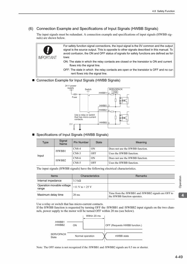
4.8 Safety Function
4-49
4
Op
era
tio
n
(6) Connection Example and Specifications of Input Signals (HWBB Signals)The input signals must be redundant. A connection example and specifications of input signals (HWBB sig-nals) are shown below.
Connection Example for Input Signals (HWBB Signals)
Specifications of Input Signals (HWBB Signals)
The input signals (HWBB signals) have the following electrical characteristics.
Use a relay or switch that has micro-current contacts.If the HWBB function is requested by turning OFF the /HWBB1 and /HWBB2 input signals on the two chan-nels, power supply to the motor will be turned OFF within 20 ms (see below).
Note: The OFF status is not recognized if the /HWBB1 and /HWBB2 signals are 0.5 ms or shorter.
For safety function signal connections, the input signal is the 0V common and the output signal is the source output. This is opposite to other signals described in this manual. To avoid confusion, the ON and OFF status of signals for safety functions are defined as fol-lows:ON: The state in which the relay contacts are closed or the transistor is ON and current
flows into the signal line.OFF: The state in which the relay contacts are open or the transistor is OFF and no cur-
rent flows into the signal line.
Type Signal Name Pin Number State Meaning
Input
/HWBB1CN8-4 ON Does not use the HWBB function.
CN8-3 OFF Uses the HWBB function.
/HWBB2CN8-6 ON Does not use the HWBB function.
CN8-5 OFF Uses the HWBB function.
24 V powersupply
Fuse
Switch SERVOPACKCN8/HWBB1+ 4
3
6
5
/HWBB1-
/HWBB2+
/HWBB2-0 V
Use a relay or switchthat has micro-currentcontacts.
Items Characteristics Remarks
Internal impedance 3.3 kΩ
Operation movable voltage range +11 V to + 25 V
Maximum delay time 20 ms Time from the /HWBB1 and /HWBB2 signals are OFF to the HWBB function operates.
Normal operationSERVOPACKState HWBB state
ON OFF (Requests HWBB function.)
Within 20 ms
/HWBB1/HWBB2
4 Operation
4.8.1 Hard Wire Base Block (HWBB) Function
4-50
(7) Operation with Utility FunctionsThe HWBB function works while the SERVOPACK operates in utility function mode.
If any of the following utility functions is being used with the /HWBB1 and /HWBB2 signals turned OFF, the SERVOPACK cannot be operated by turning ON the /HWBB1 and /HWBB2 signals. Cancel the utility func-tion first, and then set the SERVOPACK to the utility function mode again and restart operation.
• JOG operation (Fn002)• Origin search (Fn003) • Program JOG operation (Fn004)• Advanced autotuning (Fn201) • EasyFFT (Fn206)• Automatic offset-adjustment of motor current detection signal (Fn00E)
(8) Brake Signal (/BK) When the /HWBB1 or /HWBB2 signal is OFF and the HWBB function operates, the brake signal (/BK) will turn OFF. At that time, Pn506 (Brake Reference - Servo OFF Delay Time) will be disabled. Therefore, the ser-vomotor may be moved by external force until the actual brake becomes effective after the brake signal (/BK) turns ON.
Note: The brake signal output is not related to safety functions. Be sure to design the system so that the system will not be put into danger if the brake signal fails in the HWBB state. Moreover, if a servomotor with a brake is used, keep in mind that the brake for the servomotor is used only to stop the motor from moving and it cannot be used to brake the motor.
(9) Dynamic BrakeIf the dynamic brake is enabled in Pn001.0 (stopping method after servomotor power OFF), the servomotor will come to a stop under the control of the dynamic brake when the HWBB function works while the /HWBB1 or /HWBB2 signal is OFF.
Note: The dynamic brake is not related to safety function. Be sure to design the system so that the system will not be put into danger if the servomotor coasts to a stop in the HWBB state. Usually, use a sequence in which the HWBB state occurs after the servomotor is stopped using a command.
CAUTIONIf the application frequently uses the HWBB function, do not use the dynamic brake to stop the motor, or otherwise element deterioration in the SERVOPACK may result. Use a sequence in which the HWBB state occurs after the ser-vomotor has come to a stop.
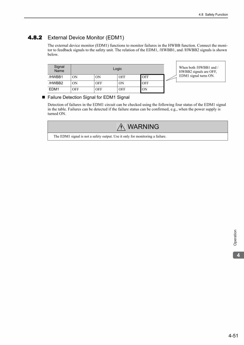
4.8 Safety Function
4-51
4
Op
era
tio
n
4.8.2 External Device Monitor (EDM1)The external device monitor (EDM1) functions to monitor failures in the HWBB function. Connect the moni-tor to feedback signals to the safety unit. The relation of the EDM1, /HWBB1, and /HWBB2 signals is shown below.
Failure Detection Signal for EDM1 SignalDetection of failures in the EDM1 circuit can be checked using the following four status of the EDM1 signal in the table. Failures can be detected if the failure status can be confirmed, e.g., when the power supply is turned ON.
Signal Name Logic
/HWBB1 ON ON OFF OFF
/HWBB2 ON OFF ON OFF
EDM1 OFF OFF OFF ON
When both /HWBB1 and /HWBB2 signals are OFF, EDM1 signal turns ON.
WARNINGThe EDM1 signal is not a safety output. Use it only for monitoring a failure.
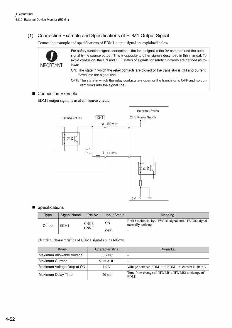
4 Operation
4.8.2 External Device Monitor (EDM1)
4-52
(1) Connection Example and Specifications of EDM1 Output SignalConnection example and specifications of EDM1 output signal are explained below.
Connection ExampleEDM1 output signal is used for source circuit.
Specifications
Electrical characteristics of EDM1 signal are as follows.
For safety function signal connections, the input signal is the 0V common and the output signal is the source output. This is opposite to other signals described in this manual. To avoid confusion, the ON and OFF status of signals for safety functions are defined as fol-lows:ON: The state in which the relay contacts are closed or the transistor is ON and current
flows into the signal line.OFF: The state in which the relay contacts are open or the transistor is OFF and no cur-
rent flows into the signal line.
24 V Power SupplySERVOPACK
External Device
EDM1+
EDM1-
0 V
8
CN8
7
Type Signal Name Pin No. Input Status Meaning
Output EDM1 CN8-8CN8-7
ON Both baseblocks by /HWBB1 signal and /HWBB2 signal normally activate.
OFF −
Items Characteristics Remarks
Maximum Allowable Voltage 30 VDC −
Maximum Current 50 m ADC −
Maximum Voltage Drop at ON 1.0 V Voltage between EDM1+ to EDM1- at current is 50 mA.
Maximum Delay Time 20 ms Time from change of /HWBB1, /HWBB2 to change of EDM1
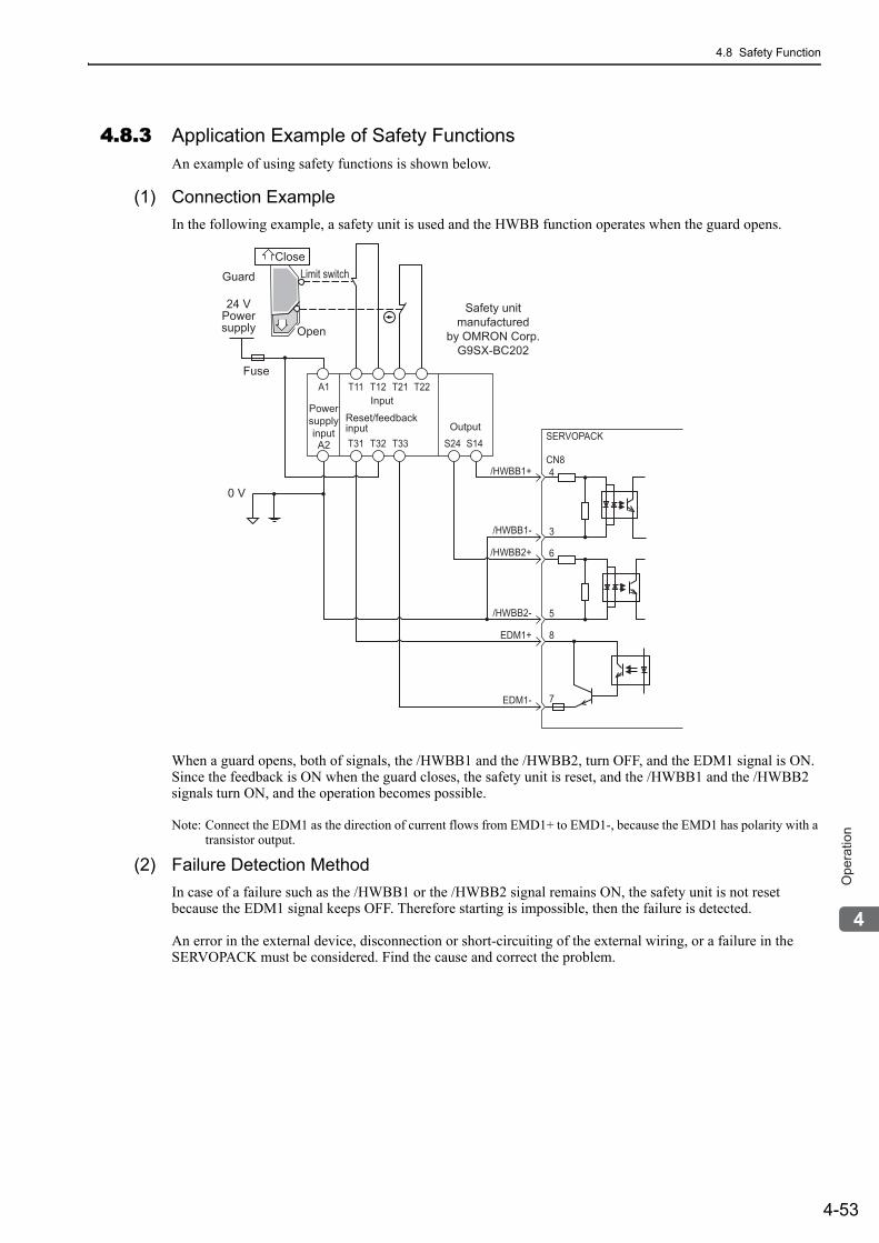
4.8 Safety Function
4-53
4
Op
era
tio
n
4.8.3 Application Example of Safety FunctionsAn example of using safety functions is shown below.
(1) Connection ExampleIn the following example, a safety unit is used and the HWBB function operates when the guard opens.
When a guard opens, both of signals, the /HWBB1 and the /HWBB2, turn OFF, and the EDM1 signal is ON. Since the feedback is ON when the guard closes, the safety unit is reset, and the /HWBB1 and the /HWBB2 signals turn ON, and the operation becomes possible.
Note: Connect the EDM1 as the direction of current flows from EMD1+ to EMD1-, because the EMD1 has polarity with a transistor output.
(2) Failure Detection MethodIn case of a failure such as the /HWBB1 or the /HWBB2 signal remains ON, the safety unit is not reset because the EDM1 signal keeps OFF. Therefore starting is impossible, then the failure is detected.
An error in the external device, disconnection or short-circuiting of the external wiring, or a failure in the SERVOPACK must be considered. Find the cause and correct the problem.
/HWBB1+
SERVOPACK
CN84
3
6
5
8
7
A1
A2
T11 T12 T21
T31 T32 T33 S24Output
S14
T22
/HWBB1-
/HWBB2+
/HWBB2-
EDM1+
EDM1-
24 VPowersupply
Guard
Safety unitmanufactured
by OMRON Corp.G9SX-BC202
Fuse
0 V
CloseLimit switch
Powersupplyinput
Input
Reset/feedbackinput
Open
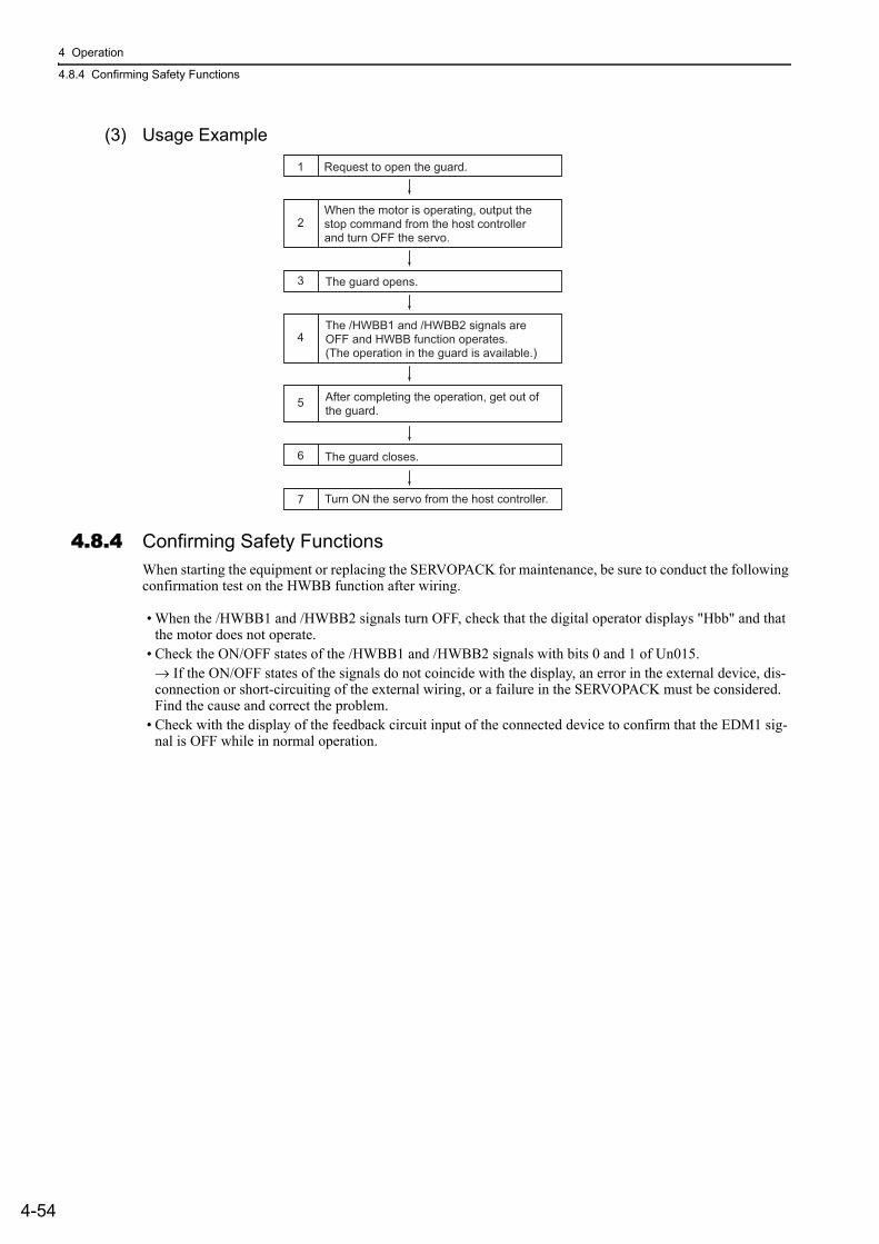
4 Operation
4.8.4 Confirming Safety Functions
4-54
(3) Usage Example
4.8.4 Confirming Safety FunctionsWhen starting the equipment or replacing the SERVOPACK for maintenance, be sure to conduct the following confirmation test on the HWBB function after wiring.
• When the /HWBB1 and /HWBB2 signals turn OFF, check that the digital operator displays "Hbb" and that the motor does not operate.
• Check the ON/OFF states of the /HWBB1 and /HWBB2 signals with bits 0 and 1 of Un015.→ If the ON/OFF states of the signals do not coincide with the display, an error in the external device, dis-connection or short-circuiting of the external wiring, or a failure in the SERVOPACK must be considered. Find the cause and correct the problem.
• Check with the display of the feedback circuit input of the connected device to confirm that the EDM1 sig-nal is OFF while in normal operation.
1
2
3
4
Request to open the guard.
When the motor is operating, output the stop command from the host controller and turn OFF the servo.
The guard opens.
The /HWBB1 and /HWBB2 signals are OFF and HWBB function operates. (The operation in the guard is available.)
5
6
7 Turn ON the servo from the host controller.
After completing the operation, get out ofthe guard.
The guard closes.
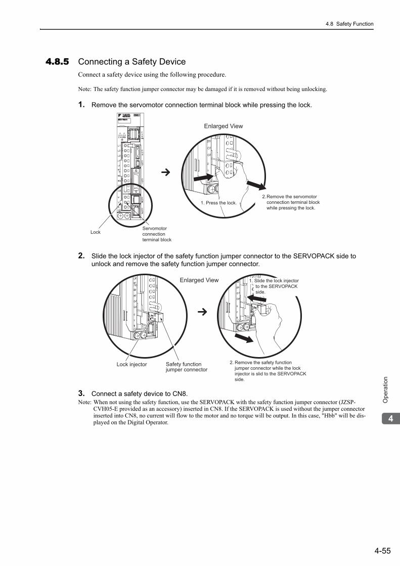
4.8 Safety Function
4-55
4
Op
era
tio
n
4.8.5 Connecting a Safety DeviceConnect a safety device using the following procedure.
Note: The safety function jumper connector may be damaged if it is removed without being unlocking.
1. Remove the servomotor connection terminal block while pressing the lock.
2. Slide the lock injector of the safety function jumper connector to the SERVOPACK side to unlock and remove the safety function jumper connector.
3. Connect a safety device to CN8.Note: When not using the safety function, use the SERVOPACK with the safety function jumper connector (JZSP-
CVH05-E provided as an accessory) inserted in CN8. If the SERVOPACK is used without the jumper connector inserted into CN8, no current will flow to the motor and no torque will be output. In this case, "Hbb" will be dis-played on the Digital Operator.
Enlarged View
1. Press the lock.Remove the servomotor connection terminal block while pressing the lock.
2.
Servomotorconnectionterminal block
Lock
Lock injector Safety function jumper connector
1. Slide the lock injector to the SERVOPACK side.
Enlarged View
Remove the safety function jumper connector while the lock injector is slid to the SERVOPACK side.
2.
4 Operation
4.8.6 Precautions for Safety Functions
4-56
4.8.6 Precautions for Safety Functions
WARNING• To check that the HWBB function satisfies the safety requirements of the system, be sure to conduct a risk
assessment of the system.Incorrect use of the machine may cause injury.
• The motor rotates if there is external force (e.g., gravity in a vertical axis) when the HWBB function is oper-ating. Therefore, use an appropriate device independently, such as a mechanical brake, that satisfies safety requirements.Incorrect use of the machine may cause injury.
• While the HWBB function is operating, the motor may rotate within an electric angle of 180° or less as a result of a SERVOPACK failure. Use the HWBB function for applications only after checking that the rota-tion of the motor will not result in a dangerous condition.Incorrect use of the machine may cause injury.
• The dynamic brake and the brake signal are not related to safety functions. Be sure to design the system that these failures will not cause a dangerous condition when the HWBB function operates.Incorrect use of the machine may cause injury.
• Connect devices meeting safety standards for the signals for safety functions.Incorrect use of the machine may cause injury.
• If the HWBB function is used for an emergency stop, turn OFF the power supply to the motor with indepen-dent electric or mechanical parts.Incorrect use of the machine may cause injury.
• The HWBB function does not turn OFF the power supply to the servo drive or electrically insulate the servo drive. When maintaining the servo drive, be sure to turn OFF the power supply to the servo drive independently.Failure to observe this warning may cause an electric shock.
5-1
5
Ad
justm
en
ts
5Adjustments
5.1 Adjustments and Basic Adjustment Procedure . . . . . . . . . . . . . . . . . . . . .5-35.1.1 Adjustments . . . . . . . . . . . . . . . . . . . . . . . . . . . . . . . . . . . . . . . . . . . . . . . . . . . . . . . . 5-35.1.2 Basic Adjustment Procedure . . . . . . . . . . . . . . . . . . . . . . . . . . . . . . . . . . . . . . . . . . . . 5-45.1.3 Monitoring Analog Signals . . . . . . . . . . . . . . . . . . . . . . . . . . . . . . . . . . . . . . . . . . . . . 5-55.1.4 Safety Precautions on Adjustment of Servo Gains . . . . . . . . . . . . . . . . . . . . . . . . . . . 5-7
5.2 Tuning-less Function . . . . . . . . . . . . . . . . . . . . . . . . . . . . . . . . . . . . . . . . 5-105.2.1 Tuning-less Function . . . . . . . . . . . . . . . . . . . . . . . . . . . . . . . . . . . . . . . . . . . . . . . . . 5-105.2.2 Tuning-less Levels Setting (Fn200) Procedure . . . . . . . . . . . . . . . . . . . . . . . . . . . . . 5-13
5.3 Advanced Autotuning (Fn201) . . . . . . . . . . . . . . . . . . . . . . . . . . . . . . . .5-165.3.1 Advanced Autotuning . . . . . . . . . . . . . . . . . . . . . . . . . . . . . . . . . . . . . . . . . . . . . . . . 5-165.3.2 Advanced Autotuning Procedure . . . . . . . . . . . . . . . . . . . . . . . . . . . . . . . . . . . . . . . 5-195.3.3 Related Parameters . . . . . . . . . . . . . . . . . . . . . . . . . . . . . . . . . . . . . . . . . . . . . . . . . 5-25
5.4 Advanced Autotuning by Reference (Fn202) . . . . . . . . . . . . . . . . . . . . .5-265.4.1 Advanced Autotuning by Reference . . . . . . . . . . . . . . . . . . . . . . . . . . . . . . . . . . . . . 5-265.4.2 Advanced Autotuning by Reference Procedure . . . . . . . . . . . . . . . . . . . . . . . . . . . . 5-295.4.3 Related Parameters . . . . . . . . . . . . . . . . . . . . . . . . . . . . . . . . . . . . . . . . . . . . . . . . . 5-33
5.5 One-parameter Tuning (Fn203) . . . . . . . . . . . . . . . . . . . . . . . . . . . . . . . 5-345.5.1 One-parameter Tuning . . . . . . . . . . . . . . . . . . . . . . . . . . . . . . . . . . . . . . . . . . . . . . . 5-345.5.2 One-parameter Tuning Procedure . . . . . . . . . . . . . . . . . . . . . . . . . . . . . . . . . . . . . . 5-365.5.3 One-parameter Tuning Example . . . . . . . . . . . . . . . . . . . . . . . . . . . . . . . . . . . . . . . . 5-425.5.4 Related Parameters . . . . . . . . . . . . . . . . . . . . . . . . . . . . . . . . . . . . . . . . . . . . . . . . . 5-43
5.6 Anti-Resonance Control Adjustment Function (Fn204) . . . . . . . . . . . . . 5-445.6.1 Anti-Resonance Control Adjustment Function . . . . . . . . . . . . . . . . . . . . . . . . . . . . . 5-445.6.2 Anti-Resonance Control Adjustment Function Operating Procedure . . . . . . . . . . . . 5-455.6.3 Related Parameters . . . . . . . . . . . . . . . . . . . . . . . . . . . . . . . . . . . . . . . . . . . . . . . . . 5-49
5.7 Vibration Suppression Function (Fn205) . . . . . . . . . . . . . . . . . . . . . . . . 5-505.7.1 Vibration Suppression Function . . . . . . . . . . . . . . . . . . . . . . . . . . . . . . . . . . . . . . . . 5-505.7.2 Vibration Suppression Function Operating Procedure . . . . . . . . . . . . . . . . . . . . . . . 5-515.7.3 Related Parameters . . . . . . . . . . . . . . . . . . . . . . . . . . . . . . . . . . . . . . . . . . . . . . . . . 5-54

5 Adjustments
5-2
5.8 Additional Adjustment Function . . . . . . . . . . . . . . . . . . . . . . . . . . . . . . . 5-555.8.1 Switching Gain Settings . . . . . . . . . . . . . . . . . . . . . . . . . . . . . . . . . . . . . . . . . . . . . . .5-555.8.2 Friction Compensation . . . . . . . . . . . . . . . . . . . . . . . . . . . . . . . . . . . . . . . . . . . . . . . .5-605.8.3 Current Control Mode Selection . . . . . . . . . . . . . . . . . . . . . . . . . . . . . . . . . . . . . . . .5-625.8.4 Current Gain Level Setting . . . . . . . . . . . . . . . . . . . . . . . . . . . . . . . . . . . . . . . . . . . .5-625.8.5 Speed Detection Method Selection . . . . . . . . . . . . . . . . . . . . . . . . . . . . . . . . . . . . . .5-62
5.9 Compatible Adjustment Function . . . . . . . . . . . . . . . . . . . . . . . . . . . . . . 5-635.9.1 Feedforward Reference . . . . . . . . . . . . . . . . . . . . . . . . . . . . . . . . . . . . . . . . . . . . . . .5-635.9.2 Using the Mode Switch (P/PI Switching) . . . . . . . . . . . . . . . . . . . . . . . . . . . . . . . . . .5-635.9.3 Torque Reference Filter . . . . . . . . . . . . . . . . . . . . . . . . . . . . . . . . . . . . . . . . . . . . . . .5-685.9.4 Position Integral Time Constant . . . . . . . . . . . . . . . . . . . . . . . . . . . . . . . . . . . . . . . . .5-70
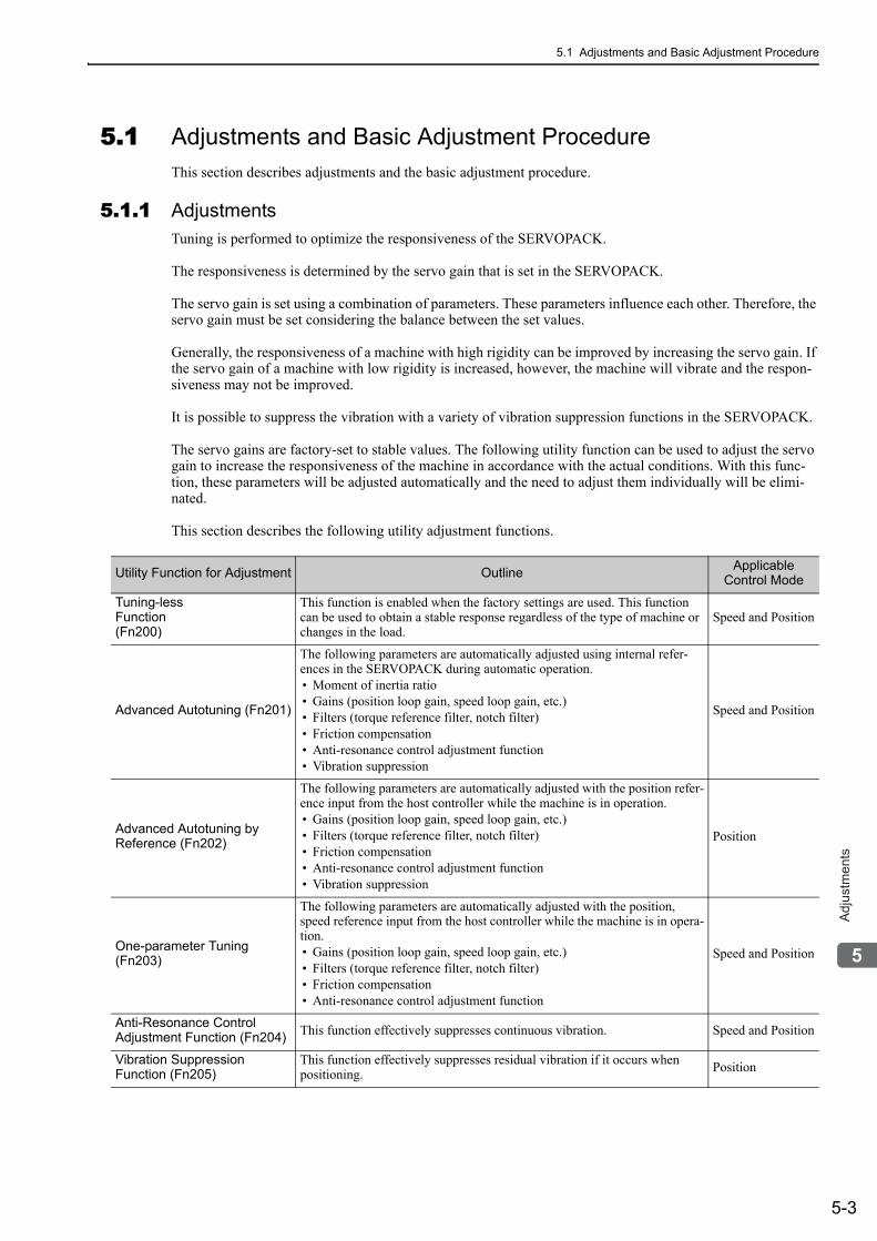
5.1 Adjustments and Basic Adjustment Procedure
5-3
5
Ad
justm
en
ts
5.1 Adjustments and Basic Adjustment ProcedureThis section describes adjustments and the basic adjustment procedure.
5.1.1 AdjustmentsTuning is performed to optimize the responsiveness of the SERVOPACK.
The responsiveness is determined by the servo gain that is set in the SERVOPACK.
The servo gain is set using a combination of parameters. These parameters influence each other. Therefore, the servo gain must be set considering the balance between the set values.
Generally, the responsiveness of a machine with high rigidity can be improved by increasing the servo gain. If the servo gain of a machine with low rigidity is increased, however, the machine will vibrate and the respon-siveness may not be improved.
It is possible to suppress the vibration with a variety of vibration suppression functions in the SERVOPACK.
The servo gains are factory-set to stable values. The following utility function can be used to adjust the servo gain to increase the responsiveness of the machine in accordance with the actual conditions. With this func-tion, these parameters will be adjusted automatically and the need to adjust them individually will be elimi-nated.
This section describes the following utility adjustment functions.
Utility Function for Adjustment Outline Applicable Control Mode
Tuning-lessFunction(Fn200)
This function is enabled when the factory settings are used. This function can be used to obtain a stable response regardless of the type of machine or changes in the load.
Speed and Position
Advanced Autotuning (Fn201)
The following parameters are automatically adjusted using internal refer-ences in the SERVOPACK during automatic operation.• Moment of inertia ratio• Gains (position loop gain, speed loop gain, etc.)• Filters (torque reference filter, notch filter)• Friction compensation• Anti-resonance control adjustment function• Vibration suppression
Speed and Position
Advanced Autotuning by Reference (Fn202)
The following parameters are automatically adjusted with the position refer-ence input from the host controller while the machine is in operation.• Gains (position loop gain, speed loop gain, etc.)• Filters (torque reference filter, notch filter)• Friction compensation• Anti-resonance control adjustment function• Vibration suppression
Position
One-parameter Tuning (Fn203)
The following parameters are automatically adjusted with the position, speed reference input from the host controller while the machine is in opera-tion.• Gains (position loop gain, speed loop gain, etc.)• Filters (torque reference filter, notch filter)• Friction compensation• Anti-resonance control adjustment function
Speed and Position
Anti-Resonance Control Adjustment Function (Fn204) This function effectively suppresses continuous vibration. Speed and Position
Vibration Suppression Function (Fn205)
This function effectively suppresses residual vibration if it occurs when positioning. Position
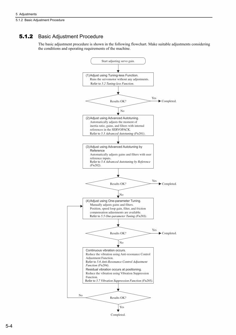
5 Adjustments
5.1.2 Basic Adjustment Procedure
5-4
5.1.2 Basic Adjustment ProcedureThe basic adjustment procedure is shown in the following flowchart. Make suitable adjustments considering the conditions and operating requirements of the machine.
Start adjusting servo gain.
(2)Adjust using Advanced Autotuning. Automatically adjusts the moment of inertia ratio, gains, and filters with internal references in the SERVOPACK.Refer to 6.2 Advanced Autotuning (Fn201).
Completed.
Completed.
(1)Adjust using Tuning-less Function. Runs the servomotor without any adjustments.Refer to 6.2 Tuning-less Function (Fn200)
(3)Adjust using Advanced Autotuning byReference Automatically adjusts gains and filters with user reference inputs. 6.4 Reference Input-type Advanced Autotuning (Fn202).
(4)Adjust using One-parameter Tuning. Manually adjusts gains and filters.Position, speed loop gain, filter, and friction compensation adjustments are available.Refer to 6.4 One-parameter Autotuning (Fn203).
Continuous vibration occurs. Reduce the vibration using Anti-resonance ControlAdjustment Function.Refer to 6.6 A-type Vibration Reduction Function (Fn204).Residual vibration occurs at positioning.Reduce the vibration using Vibration SuppressionFunction.Refer to 6.7 Vibration Reduction Function (Fn205).
Results OK?
Results OK?
Results OK?
Results OK?
Completed.
Yes
Yes
Completed.Yes
No
Yes
No
No
No
Refer to 5.2 Tuning-less Function.
Refer to 5.3 Advanced Autotuning (Fn201).
Refer to 5.4 Advanced Autotuning by Reference (Fn202).
Refer to 5.5 One-parameter Tuning (Fn203).
Refer to 5.6 Anti-Resonance Control Adjustment Function (Fn204).
Refer to 5.7 Vibration Suppression Function (Fn205).
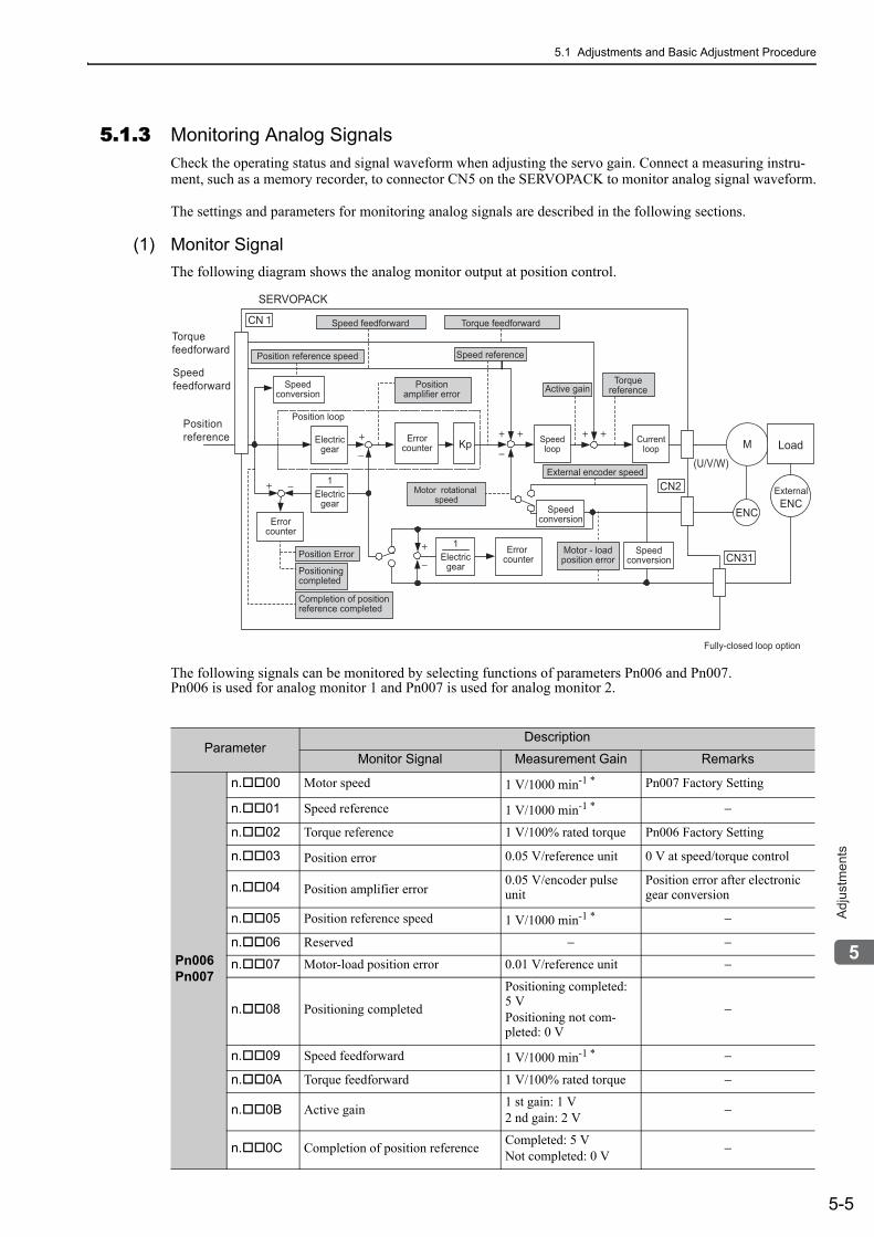
5.1 Adjustments and Basic Adjustment Procedure
5-5
5
Ad
justm
en
ts
5.1.3 Monitoring Analog SignalsCheck the operating status and signal waveform when adjusting the servo gain. Connect a measuring instru-ment, such as a memory recorder, to connector CN5 on the SERVOPACK to monitor analog signal waveform.
The settings and parameters for monitoring analog signals are described in the following sections.
(1) Monitor SignalThe following diagram shows the analog monitor output at position control.
The following signals can be monitored by selecting functions of parameters Pn006 and Pn007.Pn006 is used for analog monitor 1 and Pn007 is used for analog monitor 2.
ParameterDescription
Monitor Signal Measurement Gain Remarks
Pn006Pn007
n. 00 Motor speed 1 V/1000 min-1 * Pn007 Factory Setting
n. 01 Speed reference 1 V/1000 min-1 * −
n. 02 Torque reference 1 V/100% rated torque Pn006 Factory Setting
n. 03 Position error 0.05 V/reference unit 0 V at speed/torque control
n. 04 Position amplifier error0.05 V/encoder pulse unit
Position error after electronic gear conversion
n. 05 Position reference speed 1 V/1000 min-1 * −
n. 06 Reserved − −
n. 07 Motor-load position error 0.01 V/reference unit −
n. 08 Positioning completed
Positioning completed: 5 VPositioning not com-pleted: 0 V
−
n. 09 Speed feedforward 1 V/1000 min-1 * −
n. 0A Torque feedforward 1 V/100% rated torque −
n. 0B Active gain 1 st gain: 1 V2 nd gain: 2 V −
n. 0C Completion of position reference Completed: 5 VNot completed: 0 V −
(U/V/W)−
++
−
+ + +
Torquefeedforward
Speedfeedforward
Positionreference
+
−
−+ 1
SERVOPACK
Speed feedforward
Position reference speed
Positionamplifier error
Motor rotational speed
Speed reference
Active gainTorque
referenceSpeedconversion
Electricgear
Speedloop
Currentloop
Fully-closed loop option
Electricgear
1Electric
gear
Position loop
Torque feedforward
Errorcounter
Errorcounter
Error counter
LoadMKp
Position Error
Positioningcompleted
Completion of positionreference completed
External encoder speed
Speedconversion
Speedconversion
Motor - loadposition error CN31
ENC
CN2
CN
ExternalENC
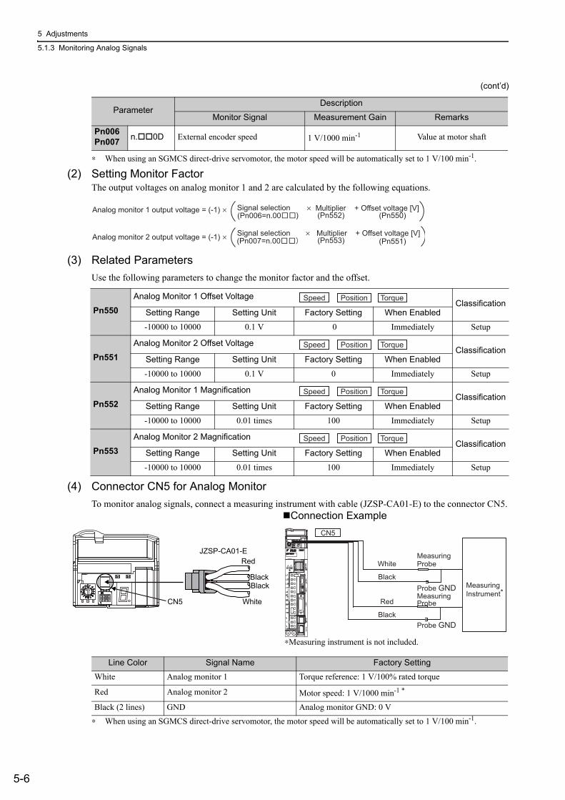
5 Adjustments
5.1.3 Monitoring Analog Signals
5-6
∗ When using an SGMCS direct-drive servomotor, the motor speed will be automatically set to 1 V/100 min-1.
(2) Setting Monitor FactorThe output voltages on analog monitor 1 and 2 are calculated by the following equations.
(3) Related ParametersUse the following parameters to change the monitor factor and the offset.
(4) Connector CN5 for Analog MonitorTo monitor analog signals, connect a measuring instrument with cable (JZSP-CA01-E) to the connector CN5.
∗ When using an SGMCS direct-drive servomotor, the motor speed will be automatically set to 1 V/100 min-1.
Pn006Pn007 n. 0D External encoder speed 1 V/1000 min-1 Value at motor shaft
(cont’d)
ParameterDescription
Monitor Signal Measurement Gain Remarks
Analog monitor 1 output voltage = (-1) ×
Analog monitor 2 output voltage = (-1) ×
(Pn006=n.00 ) (Pn552)
(Pn007=n.00
× Multiplier + Offset voltage [V]
× Multiplier + Offset voltage [V]
(Pn550)
(Pn551) (Pn553)
Signal selection
Signal selection
Pn550Analog Monitor 1 Offset Voltage
ClassificationSetting Range Setting Unit Factory Setting When Enabled
-10000 to 10000 0.1 V 0 Immediately Setup
Pn551Analog Monitor 2 Offset Voltage
ClassificationSetting Range Setting Unit Factory Setting When Enabled
-10000 to 10000 0.1 V 0 Immediately Setup
Pn552Analog Monitor 1 Magnification
ClassificationSetting Range Setting Unit Factory Setting When Enabled
-10000 to 10000 0.01 times 100 Immediately Setup
Pn553Analog Monitor 2 Magnification
ClassificationSetting Range Setting Unit Factory Setting When Enabled
-10000 to 10000 0.01 times 100 Immediately Setup
Speed Position Torque
Speed Position Torque
Speed Position Torque
Speed Position Torque
Line Color Signal Name Factory SettingWhite Analog monitor 1 Torque reference: 1 V/100% rated torque
Red Analog monitor 2 Motor speed: 1 V/1000 min-1 *
Black (2 lines) GND Analog monitor GND: 0 V
Probe GND
Probe GND
Measuring Probe
Measuring Probe
MeasuringInstrument*
White
Red
Black
Black
CN5
CN5
JZSP-CA01-E
Black
White
Red
Black
Connection Example
∗Measuring instrument is not included.
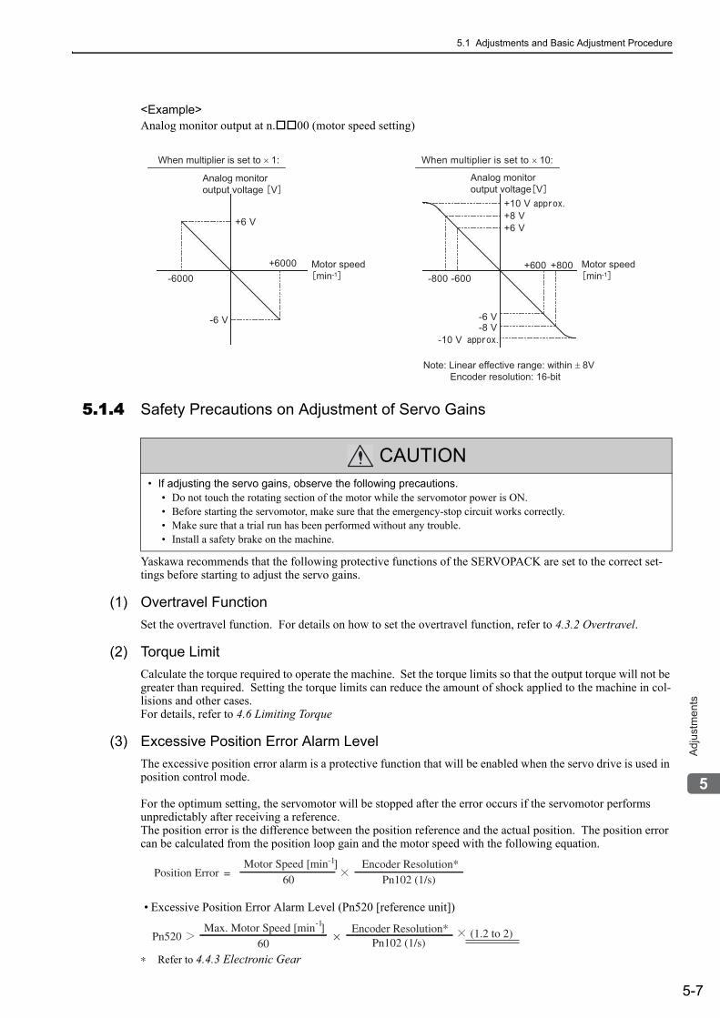
5.1 Adjustments and Basic Adjustment Procedure
5-7
5
Ad
justm
en
ts
<Example>Analog monitor output at n. 00 (motor speed setting)
5.1.4 Safety Precautions on Adjustment of Servo Gains
Yaskawa recommends that the following protective functions of the SERVOPACK are set to the correct set-tings before starting to adjust the servo gains.
(1) Overtravel FunctionSet the overtravel function. For details on how to set the overtravel function, refer to 4.3.2 Overtravel.
(2) Torque LimitCalculate the torque required to operate the machine. Set the torque limits so that the output torque will not be greater than required. Setting the torque limits can reduce the amount of shock applied to the machine in col-lisions and other cases.For details, refer to 4.6 Limiting Torque
(3) Excessive Position Error Alarm LevelThe excessive position error alarm is a protective function that will be enabled when the servo drive is used in position control mode.
For the optimum setting, the servomotor will be stopped after the error occurs if the servomotor performs unpredictably after receiving a reference.The position error is the difference between the position reference and the actual position. The position error can be calculated from the position loop gain and the motor speed with the following equation.
• Excessive Position Error Alarm Level (Pn520 [reference unit])
∗ Refer to 4.4.3 Electronic Gear
+6 V
-6 V
-600+600
+8 V
-8 V
-800+800
+10 V
-10 V
+6 V
-6 V
-6000+6000
Analog monitor output voltage V
Analog monitor output voltage V
When multiplier is set to × 1: When multiplier is set to × 10:
Motor speedmin-1
Motor speedmin-1
Note: Linear effective range: within ± 8V Encoder resolution: 16-bit
CAUTION• If adjusting the servo gains, observe the following precautions.
• Do not touch the rotating section of the motor while the servomotor power is ON.• Before starting the servomotor, make sure that the emergency-stop circuit works correctly.• Make sure that a trial run has been performed without any trouble.• Install a safety brake on the machine.
Position Error =Motor Speed [min ]-1
60Encoder Resolution*
Pn102 (1/s)
Pn520 × (1.2 to 2)Max. Motor Speed [min ]-1
60Encoder Resolution*
Pn102 (1/s)
5 Adjustments
5.1.4 Safety Precautions on Adjustment of Servo Gains
5-8
Set the level to a value that satisfies these equations, and no alarm will be generated during normal operation. The servomotor will be stopped, however, if the servomotor runs unpredictably after a reference is input or if a position error in accordance with the value set in Pn520 occurs. At the end of the equation, a coefficient is shown as "× (1.2 to 2)." This coefficient is used to add a margin that prevents a faulty alarm from occurring in actual operation of the servomotor.
If the servomotor’s maximum number of rotations is 6000 min-1 and Pn102 equals 40 with an encoder resolu-tion of 20-bit (1048576), the setting of Pn520 is calculated as shown with the following equation.
If the acceleration/deceleration of the position reference exceeds the capacity of the servomotor, the servomo-tor cannot perform at the requested speed, and the allowable level for position error will be increased as not to satisfy these equations. If so, lower the level of the acceleration/deceleration for the position reference so that the servomotor can perform at the requested speed or raise the allowable level of the position errors.
Related Parameter
Related Alarm
(4) Vibration Detection FunctionSet the vibration detection function to an appropriate value. For details on how to set the vibration detection function, refer to 6.16 Vibration Detection Level Initialization (Fn01B)
Pn102Position Loop Gain
ClassificationSetting Range Setting Unit Factory Setting When Enabled
10 to 20000 0.1 /s 400 Immediately Tuning
Speed Position
Pn520 =
2621440 × 2
5242880 (The factor setting of Pn520)
× × 26000
601048576
40
=
=
Pn520
Excessive Position Error Alarm LevelClassification
Setting Range Setting Unit Factory Setting When Enabled
1 to 1073741823(230-1)
1 reference unit 5242880 Immediately Setup
Alarm Display Alarm Name Alarm Contents
A.d00 Position Error Pulse Overflow Position error pulses exceeded parameter Pn520.
Position
5.1 Adjustments and Basic Adjustment Procedure
5-9
5
Ad
justm
en
ts
(5) Excessive Position Error Alarm Level at Servo ONIf the servomotor is turned ON when position error pulses remain, the servomotor will return to the home posi-tion and reset the number of pulses to zero. To prevent the servomotor from moving suddenly, select the appropriate level for the Excessive Position Error alarm when the servomotor is ON to restrict operation of the servomotor.
Related Parameters
Related Alarm
When an alarm occurs, refer to 9 Troubleshooting and take the corrective actions.
Pn526
Excessive Position Error Alarm Level at Servo ONClassification
Setting Range Setting Unit Factory Setting When Enabled
1 to 1073741823(230-1)
1 reference unit 5242880 Immediately Setup
Position
Pn528
Excessive Position Error Warning Level at Servo ON Classification
Setting Range Setting Unit Factory Setting When Enabled
10 to 100 1% 100 Immediately Setup
Pn529
Speed Limit Level at Servo ONClassification
Setting Range Setting Unit Factory Setting When Enabled
0 to 10000 1 min-1 10000 Immediately Setup
Position
Position
Alarm Display Alarm Name Alarm Contents
A.d01Position Error Pulse Overflow Alarm at Servo ON
Occurs if the SV_ON command is received when the number of position error pulses is greater than the set value of Pn526.
A.d02Position Error Pulse Overflow Alarm by Speed Limit at Servo ON
After a position error pulse has been input, Pn529 limits the speed if the SV_ON command is received. If Pn529 limits the speed in such a state, this alarm occurs when the position references are input and the number of posi-tion error pulses exceeds the value set for parameter Pn520 (Excessive Posi-tion Error Alarm Level).
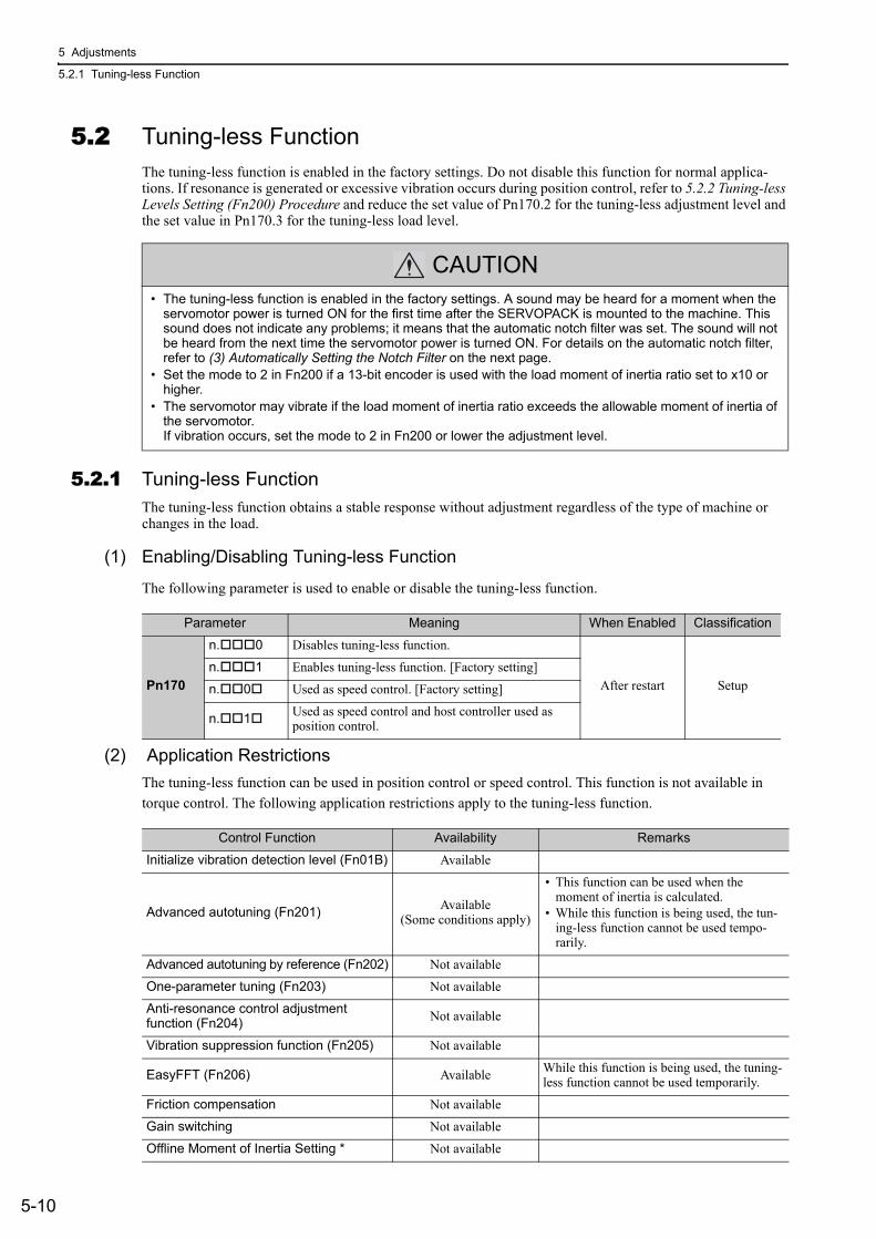
5 Adjustments
5.2.1 Tuning-less Function
5-10
5.2 Tuning-less Function The tuning-less function is enabled in the factory settings. Do not disable this function for normal applica-tions. If resonance is generated or excessive vibration occurs during position control, refer to 5.2.2 Tuning-less Levels Setting (Fn200) Procedure and reduce the set value of Pn170.2 for the tuning-less adjustment level and the set value in Pn170.3 for the tuning-less load level.
5.2.1 Tuning-less FunctionThe tuning-less function obtains a stable response without adjustment regardless of the type of machine or changes in the load.
(1) Enabling/Disabling Tuning-less Function
The following parameter is used to enable or disable the tuning-less function.
(2) Application RestrictionsThe tuning-less function can be used in position control or speed control. This function is not available in torque control. The following application restrictions apply to the tuning-less function.
CAUTION• The tuning-less function is enabled in the factory settings. A sound may be heard for a moment when the
servomotor power is turned ON for the first time after the SERVOPACK is mounted to the machine. This sound does not indicate any problems; it means that the automatic notch filter was set. The sound will not be heard from the next time the servomotor power is turned ON. For details on the automatic notch filter, refer to (3) Automatically Setting the Notch Filter on the next page.
• Set the mode to 2 in Fn200 if a 13-bit encoder is used with the load moment of inertia ratio set to x10 or higher.
• The servomotor may vibrate if the load moment of inertia ratio exceeds the allowable moment of inertia of the servomotor.If vibration occurs, set the mode to 2 in Fn200 or lower the adjustment level.
Parameter Meaning When Enabled Classification
Pn170
n. 0 Disables tuning-less function.
After restart Setupn. 1 Enables tuning-less function. [Factory setting]
n. 0 Used as speed control. [Factory setting]
n. 1 Used as speed control and host controller used as position control.
Control Function Availability Remarks
Initialize vibration detection level (Fn01B) Available
Advanced autotuning (Fn201) Available (Some conditions apply)
• This function can be used when the moment of inertia is calculated.
• While this function is being used, the tun-ing-less function cannot be used tempo-rarily.
Advanced autotuning by reference (Fn202) Not available
One-parameter tuning (Fn203) Not available
Anti-resonance control adjustment function (Fn204) Not available
Vibration suppression function (Fn205) Not available
EasyFFT (Fn206) Available While this function is being used, the tuning-less function cannot be used temporarily.
Friction compensation Not available
Gain switching Not available
Offline Moment of Inertia Setting * Not available
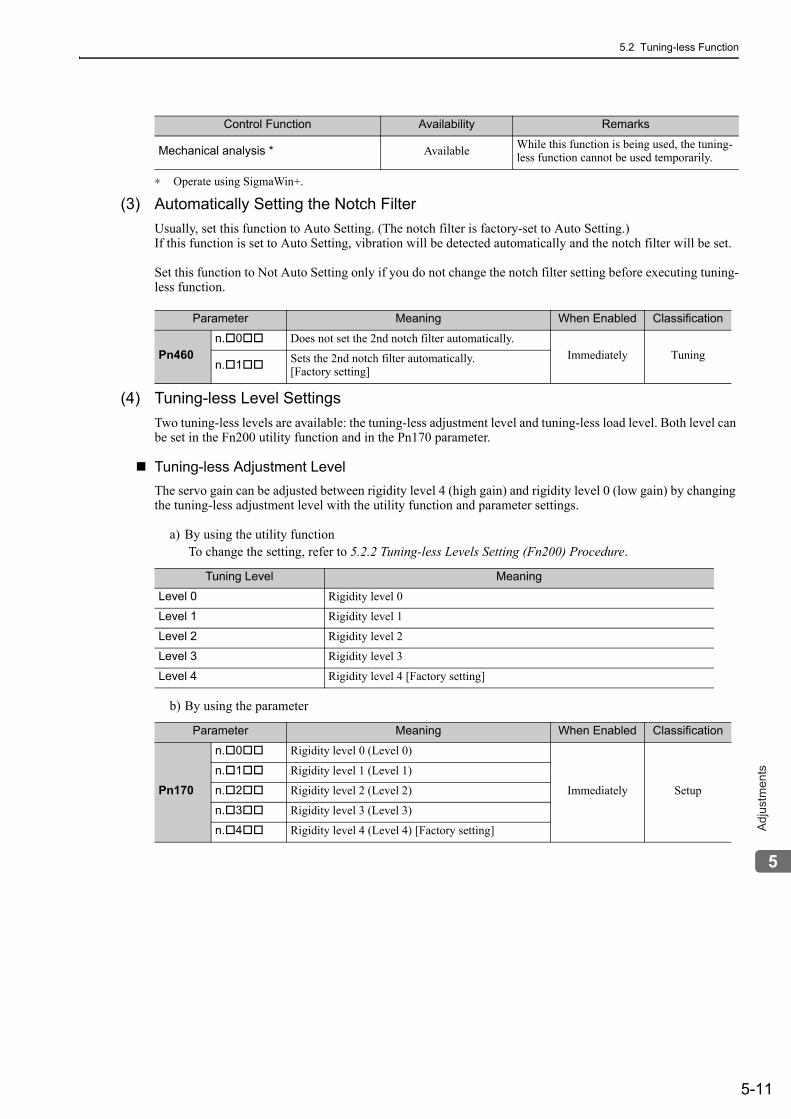
5.2 Tuning-less Function
5-11
5
Ad
justm
en
ts
∗ Operate using SigmaWin+.
(3) Automatically Setting the Notch FilterUsually, set this function to Auto Setting. (The notch filter is factory-set to Auto Setting.)If this function is set to Auto Setting, vibration will be detected automatically and the notch filter will be set.
Set this function to Not Auto Setting only if you do not change the notch filter setting before executing tuning-less function.
(4) Tuning-less Level SettingsTwo tuning-less levels are available: the tuning-less adjustment level and tuning-less load level. Both level can be set in the Fn200 utility function and in the Pn170 parameter.
Tuning-less Adjustment LevelThe servo gain can be adjusted between rigidity level 4 (high gain) and rigidity level 0 (low gain) by changing the tuning-less adjustment level with the utility function and parameter settings.
a) By using the utility functionTo change the setting, refer to 5.2.2 Tuning-less Levels Setting (Fn200) Procedure.
b) By using the parameter
Mechanical analysis * Available While this function is being used, the tuning-less function cannot be used temporarily.
Control Function Availability Remarks
Parameter Meaning When Enabled Classification
Pn460n. 0 Does not set the 2nd notch filter automatically.
Immediately Tuningn. 1 Sets the 2nd notch filter automatically.
[Factory setting]
Tuning Level Meaning
Level 0 Rigidity level 0
Level 1 Rigidity level 1
Level 2 Rigidity level 2
Level 3 Rigidity level 3
Level 4 Rigidity level 4 [Factory setting]
Parameter Meaning When Enabled Classification
Pn170
n. 0 Rigidity level 0 (Level 0)
Immediately Setup
n. 1 Rigidity level 1 (Level 1)
n. 2 Rigidity level 2 (Level 2)
n. 3 Rigidity level 3 (Level 3)
n. 4 Rigidity level 4 (Level 4) [Factory setting]
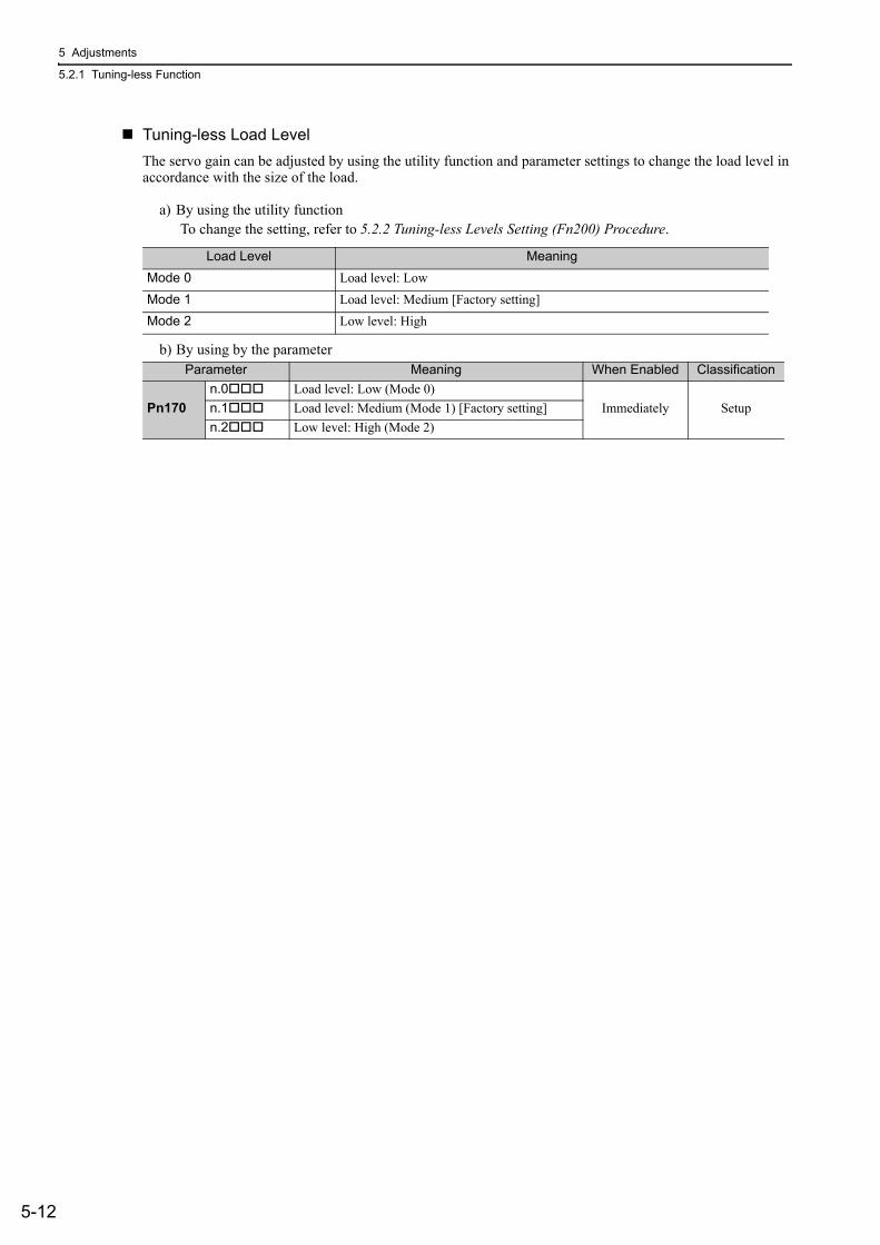
5 Adjustments
5.2.1 Tuning-less Function
5-12
Tuning-less Load LevelThe servo gain can be adjusted by using the utility function and parameter settings to change the load level in accordance with the size of the load.
a) By using the utility functionTo change the setting, refer to 5.2.2 Tuning-less Levels Setting (Fn200) Procedure.
b) By using by the parameter
Load Level MeaningMode 0 Load level: LowMode 1 Load level: Medium [Factory setting]Mode 2 Low level: High
Parameter Meaning When Enabled Classification
Pn170n.0 Load level: Low (Mode 0)
Immediately Setupn.1 Load level: Medium (Mode 1) [Factory setting]n.2 Low level: High (Mode 2)
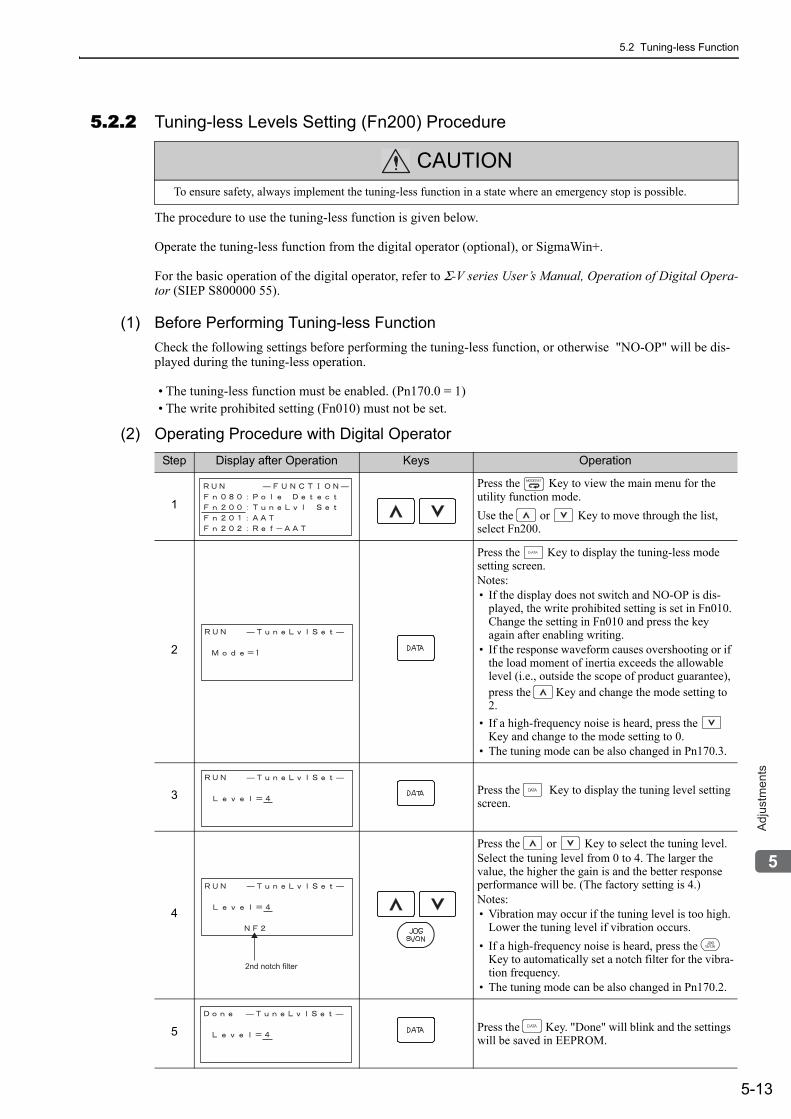
5.2 Tuning-less Function
5-13
5
Ad
justm
en
ts
5.2.2 Tuning-less Levels Setting (Fn200) Procedure
The procedure to use the tuning-less function is given below.
Operate the tuning-less function from the digital operator (optional), or SigmaWin+.
For the basic operation of the digital operator, refer to Σ-V series User’s Manual, Operation of Digital Opera-tor (SIEP S800000 55).
(1) Before Performing Tuning-less FunctionCheck the following settings before performing the tuning-less function, or otherwise "NO-OP" will be dis-played during the tuning-less operation.
• The tuning-less function must be enabled. (Pn170.0 = 1)• The write prohibited setting (Fn010) must not be set.
(2) Operating Procedure with Digital Operator
CAUTIONTo ensure safety, always implement the tuning-less function in a state where an emergency stop is possible.
Step Display after Operation Keys Operation
1
Press the Key to view the main menu for the utility function mode.Use the or Key to move through the list, select Fn200.
2
Press the Key to display the tuning-less mode setting screen.Notes:• If the display does not switch and NO-OP is dis-
played, the write prohibited setting is set in Fn010.Change the setting in Fn010 and press the key again after enabling writing.
• If the response waveform causes overshooting or if the load moment of inertia exceeds the allowable level (i.e., outside the scope of product guarantee), press the Key and change the mode setting to 2.
• If a high-frequency noise is heard, press the Key and change to the mode setting to 0.
• The tuning mode can be also changed in Pn170.3.
3 Press the Key to display the tuning level setting screen.
4
Press the or Key to select the tuning level.Select the tuning level from 0 to 4. The larger the value, the higher the gain is and the better response performance will be. (The factory setting is 4.)Notes:• Vibration may occur if the tuning level is too high.
Lower the tuning level if vibration occurs.• If a high-frequency noise is heard, press the
Key to automatically set a notch filter for the vibra-tion frequency.
• The tuning mode can be also changed in Pn170.2.
5 Press the Key. "Done" will blink and the settings will be saved in EEPROM.
2nd notch filter
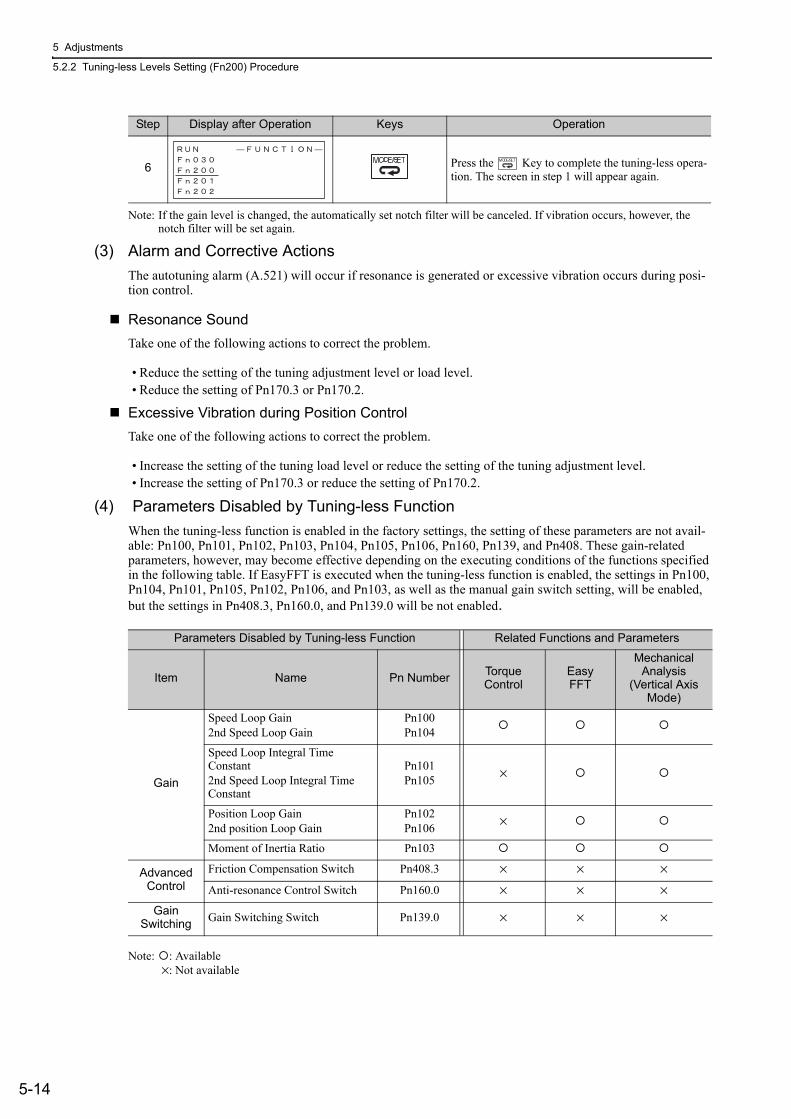
5 Adjustments
5.2.2 Tuning-less Levels Setting (Fn200) Procedure
5-14
Note: If the gain level is changed, the automatically set notch filter will be canceled. If vibration occurs, however, the notch filter will be set again.
(3) Alarm and Corrective ActionsThe autotuning alarm (A.521) will occur if resonance is generated or excessive vibration occurs during posi-tion control.
Resonance SoundTake one of the following actions to correct the problem.
• Reduce the setting of the tuning adjustment level or load level.• Reduce the setting of Pn170.3 or Pn170.2.
Excessive Vibration during Position ControlTake one of the following actions to correct the problem.
• Increase the setting of the tuning load level or reduce the setting of the tuning adjustment level.• Increase the setting of Pn170.3 or reduce the setting of Pn170.2.
(4) Parameters Disabled by Tuning-less FunctionWhen the tuning-less function is enabled in the factory settings, the setting of these parameters are not avail-able: Pn100, Pn101, Pn102, Pn103, Pn104, Pn105, Pn106, Pn160, Pn139, and Pn408. These gain-related parameters, however, may become effective depending on the executing conditions of the functions specified in the following table. If EasyFFT is executed when the tuning-less function is enabled, the settings in Pn100, Pn104, Pn101, Pn105, Pn102, Pn106, and Pn103, as well as the manual gain switch setting, will be enabled, but the settings in Pn408.3, Pn160.0, and Pn139.0 will be not enabled.
Note: : Available ×: Not available
6 Press the Key to complete the tuning-less opera-tion. The screen in step 1 will appear again.
Step Display after Operation Keys Operation
Parameters Disabled by Tuning-less Function Related Functions and Parameters
Item Name Pn Number Torque Control
EasyFFT
Mechanical Analysis
(Vertical Axis Mode)
Gain
Speed Loop Gain2nd Speed Loop Gain
Pn100Pn104
Speed Loop Integral Time Constant2nd Speed Loop Integral Time Constant
Pn101Pn105 ×
Position Loop Gain2nd position Loop Gain
Pn102Pn106 ×
Moment of Inertia Ratio Pn103
Advanced Control
Friction Compensation Switch Pn408.3 × × ×Anti-resonance Control Switch Pn160.0 × × ×
Gain Switching Gain Switching Switch Pn139.0 × × ×
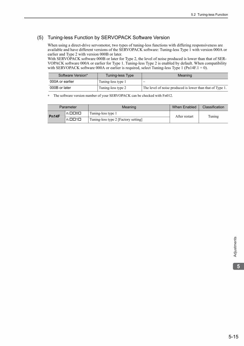
5.2 Tuning-less Function
5-15
5
Ad
justm
en
ts
(5) Tuning-less Function by SERVOPACK Software VersionWhen using a direct-drive servomotor, two types of tuning-less functions with differing responsiveness are available and have different versions of the SERVOPACK software: Tuning-less Type 1 with version 000A or earlier and Type 2 with version 000B or later. With SERVOPACK software 000B or later for Type 2, the level of noise produced is lower than that of SER-VOPACK software 000A or earlier for Type 1. Tuning-less Type 2 is enabled by default. When compatibility with SERVOPACK software 000A or earlier is required, select Tuning-less Type 1 (Pn14F.1 = 0).
∗ The software version number of your SERVOPACK can be checked with Fn012.
Software Version* Tuning-less Type Meaning
000A or earlier Tuning-less type 1 −
000B or later Tuning-less type 2 The level of noise produced is lower than that of Type 1.
Parameter Meaning When Enabled Classification
Pn14Fn. 0 Tuning-less type 1
After restart Tuningn. 1 Tuning-less type 2 [Factory setting]
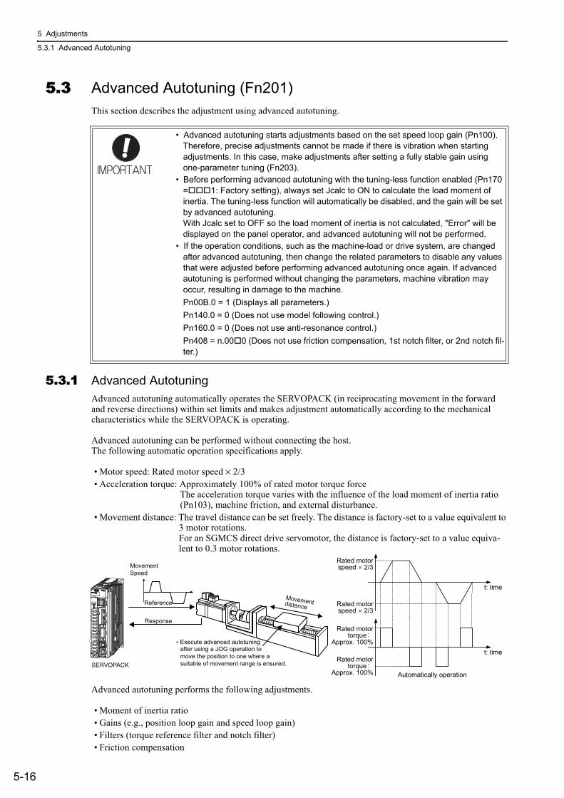
5 Adjustments
5.3.1 Advanced Autotuning
5-16
5.3 Advanced Autotuning (Fn201)This section describes the adjustment using advanced autotuning.
5.3.1 Advanced AutotuningAdvanced autotuning automatically operates the SERVOPACK (in reciprocating movement in the forward and reverse directions) within set limits and makes adjustment automatically according to the mechanical characteristics while the SERVOPACK is operating.
Advanced autotuning can be performed without connecting the host.The following automatic operation specifications apply.
• Motor speed: Rated motor speed × 2/3• Acceleration torque: Approximately 100% of rated motor torque force
The acceleration torque varies with the influence of the load moment of inertia ratio (Pn103), machine friction, and external disturbance.
• Movement distance: The travel distance can be set freely. The distance is factory-set to a value equivalent to 3 motor rotations.For an SGMCS direct drive servomotor, the distance is factory-set to a value equiva-lent to 0.3 motor rotations.
Advanced autotuning performs the following adjustments.
• Moment of inertia ratio• Gains (e.g., position loop gain and speed loop gain)• Filters (torque reference filter and notch filter)• Friction compensation
• Advanced autotuning starts adjustments based on the set speed loop gain (Pn100). Therefore, precise adjustments cannot be made if there is vibration when starting adjustments. In this case, make adjustments after setting a fully stable gain using one-parameter tuning (Fn203).
• Before performing advanced autotuning with the tuning-less function enabled (Pn170 = 1: Factory setting), always set Jcalc to ON to calculate the load moment of inertia. The tuning-less function will automatically be disabled, and the gain will be set by advanced autotuning.With Jcalc set to OFF so the load moment of inertia is not calculated, "Error" will be displayed on the panel operator, and advanced autotuning will not be performed.
• If the operation conditions, such as the machine-load or drive system, are changed after advanced autotuning, then change the related parameters to disable any values that were adjusted before performing advanced autotuning once again. If advanced autotuning is performed without changing the parameters, machine vibration may occur, resulting in damage to the machine.Pn00B.0 = 1 (Displays all parameters.)Pn140.0 = 0 (Does not use model following control.)Pn160.0 = 0 (Does not use anti-resonance control.)Pn408 = n.00 0 (Does not use friction compensation, 1st notch filter, or 2nd notch fil-ter.)
Movementdistance
SERVOPACK
MovementSpeed
Reference
Response
* Execute advanced autotuning after using a JOG operation to move the position to one where a suitable of movement range is ensured.
t: time
t: time
Rated motorspeed × 2/3
Rated motorspeed × 2/3
Rated motortorque
Approx. 100%
Rated motortorque
Approx. 100% Automatically operation
5.3 Advanced Autotuning (Fn201)
5-17
5
Ad
justm
en
ts
• Anti-resonance control• Vibration suppression (Mode = 2 or 3)
Refer to 5.3.3 Related Parameters for parameters used for adjustments.
(1) Before Performing Advanced AutotuningCheck the following settings before performing advanced autotuning.
a) A message (NO-OP) indicating that no operations are possible will be displayed, if all of the following conditions are not met.
• The main circuit power supply must be ON.• The servomotor power must be OFF.• The forward run prohibited (P-OT) and the reverse run prohibited (N-OT) signals must not be in an over-
travel state.• The control must not be set to torque control.• Automatic gain switching must be disabled.• Gain setting 2 must not be selected.• Test without motor function must not be enabled. (Pn00C.0 = 0)• All alarms and warning must be cleared.• The hardwire baseblock (HWBB) must be off.b) Observe the following condition to ensure operation.• The write prohibited setting (Fn010) must not be set.
Note: If advanced autotuning is started while the SERVOPACK is in speed control, the mode will change to position con-trol automatically to perform advanced autotuning. The mode will return to speed control after completing the adjustment. To perform advanced autotuning in speed control, set the motor to 1. (Mode = 1)
(2) When Advanced Autotuning Cannot be PerformedAdvanced autotuning cannot be performed normally under the following conditions. If any of the following conditions exists, perform advanced autotuning by reference or one-parameter tuning.
Refer to 5.4 Advanced Autotuning by Reference (Fn202) and 5.5 One-parameter Tuning (Fn203) for details.
• The machine system can work only in a single direction.• The operating range is within 0.5 rotations (Also for SGMCS direct drive motors, the operating range is
within 0.05 rotations).
(3) When Advanced Autotuning Cannot be AdjustedAdvanced autotuning may not be performed normally under the following conditions. If the result of autotun-ing is not satisfactory, perform advanced autotuning by reference or one-parameter tuning.
Refer to 5.4 Advanced Autotuning by Reference (Fn202) and 5.5 One-parameter Tuning (Fn203) for details.
• The operating range is not applicable.• The moment of inertia changes within the set operating range.• The machine has high friction.• The rigidity of the load is low and vibration occurs when positioning is performed.• The position integration function is used.• P control operation (proportional control) is performed.Note:If a setting is made for calculating the moment of inertia, an error will result when P control operation is selected
using /P-CON signal while the moment of inertia is being calculated.
CAUTION• Because advanced autotuning adjusts the SERVOPACK during automatic operation, vibration or over-
shooting may occur. To ensure safety, perform advanced autotuning in a state where the SERVOPACK can come to an emergency stop at any time.
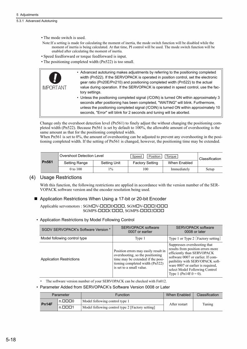
5 Adjustments
5.3.1 Advanced Autotuning
5-18
• The mode switch is used.Note:If a setting is made for calculating the moment of inertia, the mode switch function will be disabled while the
moment of inertia is being calculated. At that time, PI control will be used. The mode switch function will be enabled after calculating the moment of inertia.
• Speed feedforward or torque feedforward is input.• The positioning completed width (Pn522) is too small.
Change only the overshoot detection level (Pn561) to finely adjust the without changing the positioning com-pleted width (Pn522). Because Pn561 is set by default to 100%, the allowable amount of overshooting is the same amount as that for the positioning completed width. When Pn561 is set to 0%, the amount of overshooting can be adjusted to prevent any overshooting in the posi-tioning completed width. If the setting of Pn561 is changed, however, the positioning time may be extended.
(4) Usage RestrictionsWith this function, the following restrictions are applied in accordance with the version number of the SER-VOPACK software version and the encoder resolution being used.
Application Restrictions When Using a 17-bit or 20-bit EncoderApplicable servomotors : SGM V- D , SGM V- 3
SGMPS- C , SGMPS- 2
• Application Restrictions by Model Following Control
∗ The software version number of your SERVOPACK can be checked with Fn012.• Parameter Added from SERVOPACK’s Software Version 0008 or Later
• Advanced autotuning makes adjustments by referring to the positioning completed width (Pn522). If the SERVOPACK is operated in position control, set the electronic gear ratio (Pn20E/Pn210) and positioning completed width (Pn522) to the actual value during operation. If the SERVOPACK is operated in speed control, use the fac-tory settings.
• Unless the positioning completed signal (/COIN) is turned ON within approximately 3 seconds after positioning has been completed, "WAITING" will blink. Furthermore, unless the positioning completed signal (/COIN) is turned ON within approximately 10 seconds, "Error" will blink for 2 seconds and tuning will be aborted.
Pn561Overshoot Detection Level
ClassificationSetting Range Setting Unit Factory Setting When Enabled
0 to 100 1% 100 Immediately Setup
Speed Position Torque
SGDV SERVOPACK's Software Version * SERVOPACK software0007 or earlier
SERVOPACK software0008 or later
Model following control type Type 1 Type 1 or Type 2 [Factory setting]
Application Restrictions
Position errors may easily result in overshooting, so the positioning time may be extended if the posi-tioning completed width (Pn522) is set to a small value.
Suppresses overshooting that results from position errors more efficiently than SERVOPACK software 0007 or earlier. If com-patibility with SERVOPACK soft-ware 0007 or earlier is required, select Model Following Control Type 1 (Pn14F.0 = 0).
Parameter Function When Enabled Classification
Pn14Fn. 0 Model following control type 1
After restart Tuningn. 1 Model following control type 2 [Factory setting]
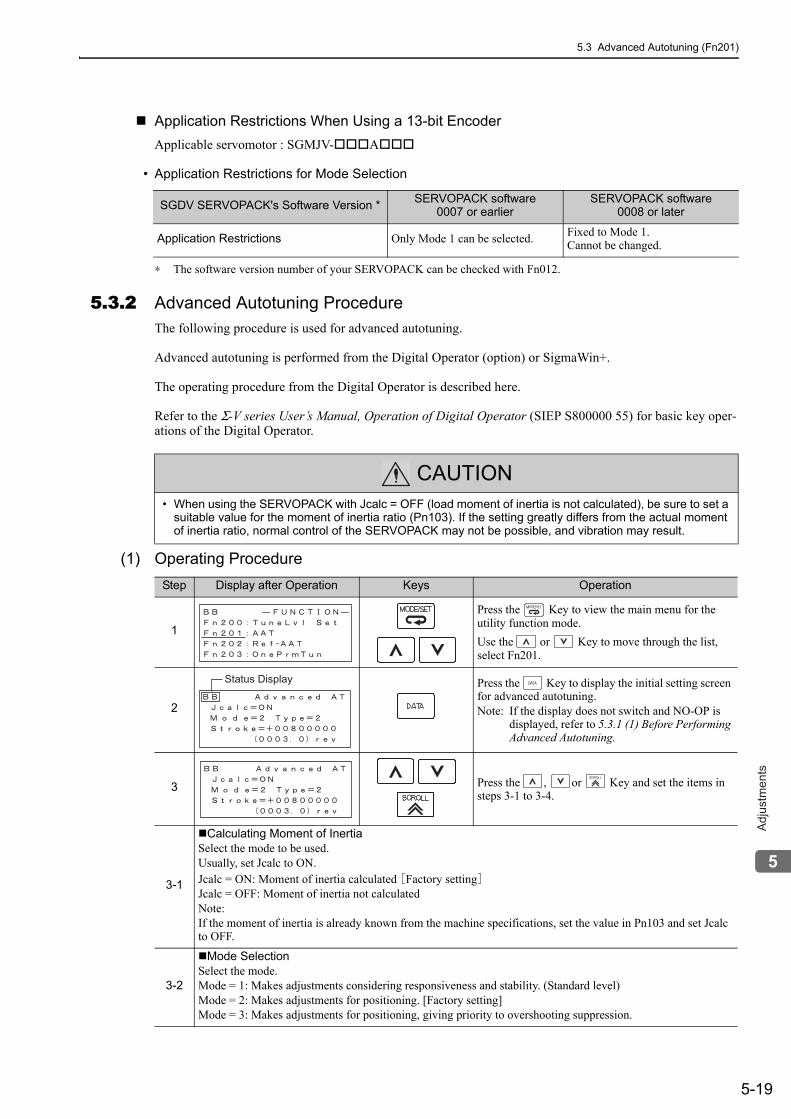
5.3 Advanced Autotuning (Fn201)
5-19
5
Ad
justm
en
ts
Application Restrictions When Using a 13-bit EncoderApplicable servomotor : SGMJV- A
• Application Restrictions for Mode Selection
∗ The software version number of your SERVOPACK can be checked with Fn012.
5.3.2 Advanced Autotuning Procedure The following procedure is used for advanced autotuning.
Advanced autotuning is performed from the Digital Operator (option) or SigmaWin+.
The operating procedure from the Digital Operator is described here.
Refer to the Σ-V series User’s Manual, Operation of Digital Operator (SIEP S800000 55) for basic key oper-ations of the Digital Operator.
(1) Operating Procedure
SGDV SERVOPACK's Software Version * SERVOPACK software0007 or earlier
SERVOPACK software0008 or later
Application Restrictions Only Mode 1 can be selected. Fixed to Mode 1.Cannot be changed.
CAUTION• When using the SERVOPACK with Jcalc = OFF (load moment of inertia is not calculated), be sure to set a
suitable value for the moment of inertia ratio (Pn103). If the setting greatly differs from the actual moment of inertia ratio, normal control of the SERVOPACK may not be possible, and vibration may result.
Step Display after Operation Keys Operation
1
Press the Key to view the main menu for the utility function mode.Use the or Key to move through the list, select Fn201.
2
Press the Key to display the initial setting screen for advanced autotuning.Note: If the display does not switch and NO-OP is
displayed, refer to 5.3.1 (1) Before Performing Advanced Autotuning.
3 Press the , or Key and set the items in steps 3-1 to 3-4.
3-1
Calculating Moment of InertiaSelect the mode to be used.Usually, set Jcalc to ON.Jcalc = ON: Moment of inertia calculated [Factory setting]Jcalc = OFF: Moment of inertia not calculatedNote:If the moment of inertia is already known from the machine specifications, set the value in Pn103 and set Jcalc to OFF.
3-2
Mode SelectionSelect the mode.Mode = 1: Makes adjustments considering responsiveness and stability. (Standard level)Mode = 2: Makes adjustments for positioning. [Factory setting]Mode = 3: Makes adjustments for positioning, giving priority to overshooting suppression.
Status Display
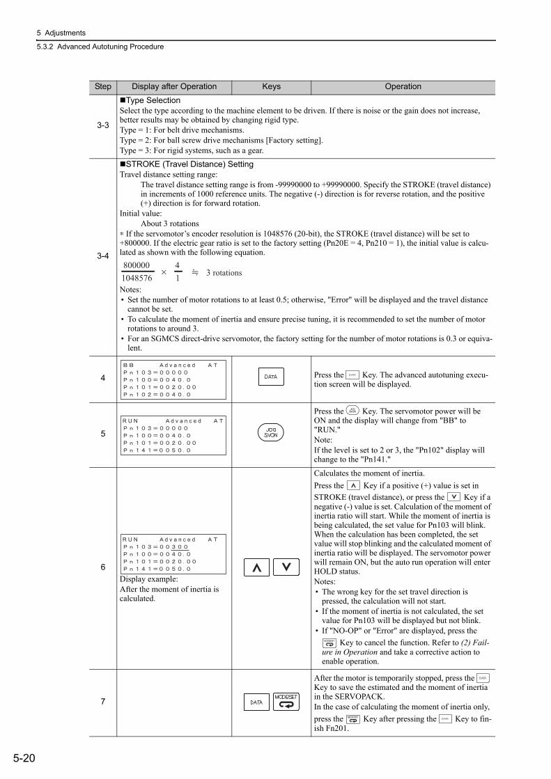
5 Adjustments
5.3.2 Advanced Autotuning Procedure
5-20
3-3
Type SelectionSelect the type according to the machine element to be driven. If there is noise or the gain does not increase, better results may be obtained by changing rigid type.Type = 1: For belt drive mechanisms.Type = 2: For ball screw drive mechanisms [Factory setting].Type = 3: For rigid systems, such as a gear.
3-4
STROKE (Travel Distance) SettingTravel distance setting range:
The travel distance setting range is from -99990000 to +99990000. Specify the STROKE (travel distance) in increments of 1000 reference units. The negative (-) direction is for reverse rotation, and the positive (+) direction is for forward rotation.
Initial value:About 3 rotations
∗ If the servomotor’s encoder resolution is 1048576 (20-bit), the STROKE (travel distance) will be set to +800000. If the electric gear ratio is set to the factory setting (Pn20E = 4, Pn210 = 1), the initial value is calcu-lated as shown with the following equation.
Notes:• Set the number of motor rotations to at least 0.5; otherwise, "Error" will be displayed and the travel distance
cannot be set.• To calculate the moment of inertia and ensure precise tuning, it is recommended to set the number of motor
rotations to around 3.• For an SGMCS direct-drive servomotor, the factory setting for the number of motor rotations is 0.3 or equiva-
lent.
4 Press the Key. The advanced autotuning execu-tion screen will be displayed.
5
Press the Key. The servomotor power will be ON and the display will change from "BB" to "RUN."Note:If the level is set to 2 or 3, the "Pn102" display will change to the "Pn141."
6Display example:After the moment of inertia is calculated.
Calculates the moment of inertia.Press the Key if a positive (+) value is set in STROKE (travel distance), or press the Key if a negative (-) value is set. Calculation of the moment of inertia ratio will start. While the moment of inertia is being calculated, the set value for Pn103 will blink. When the calculation has been completed, the set value will stop blinking and the calculated moment of inertia ratio will be displayed. The servomotor power will remain ON, but the auto run operation will enter HOLD status.Notes:• The wrong key for the set travel direction is
pressed, the calculation will not start.• If the moment of inertia is not calculated, the set
value for Pn103 will be displayed but not blink.• If "NO-OP" or "Error" are displayed, press the
Key to cancel the function. Refer to (2) Fail-ure in Operation and take a corrective action to enable operation.
7
After the motor is temporarily stopped, press the Key to save the estimated and the moment of inertia in the SERVOPACK.In the case of calculating the moment of inertia only, press the Key after pressing the Key to fin-ish Fn201.
Step Display after Operation Keys Operation
×8000001048576
41 3 rotations
d v a n c e d
R U N d v a n c e d
R U N d v a n c e d
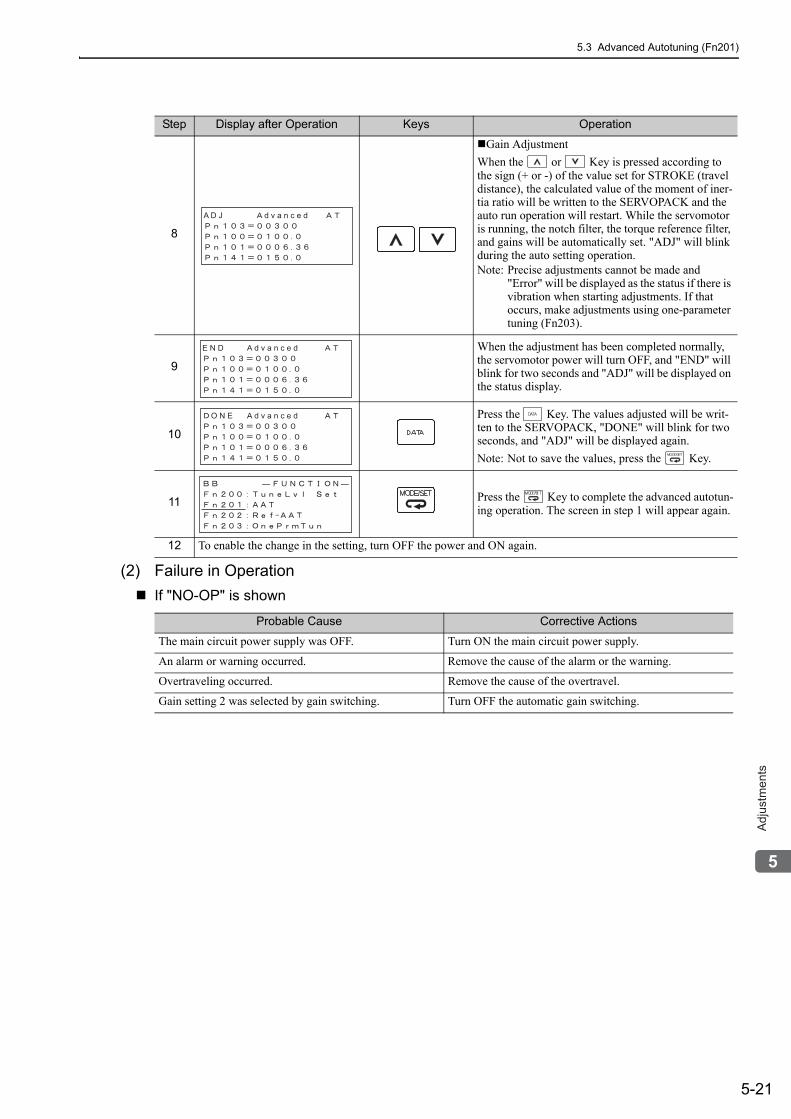
5.3 Advanced Autotuning (Fn201)
5-21
5
Ad
justm
en
ts
(2) Failure in OperationIf "NO-OP" is shown
8
Gain AdjustmentWhen the or Key is pressed according to the sign (+ or -) of the value set for STROKE (travel distance), the calculated value of the moment of iner-tia ratio will be written to the SERVOPACK and the auto run operation will restart. While the servomotor is running, the notch filter, the torque reference filter, and gains will be automatically set. "ADJ" will blink during the auto setting operation.Note: Precise adjustments cannot be made and
"Error" will be displayed as the status if there is vibration when starting adjustments. If that occurs, make adjustments using one-parameter tuning (Fn203).
9
When the adjustment has been completed normally, the servomotor power will turn OFF, and "END" will blink for two seconds and "ADJ" will be displayed on the status display.
10
Press the Key. The values adjusted will be writ-ten to the SERVOPACK, "DONE" will blink for two seconds, and "ADJ" will be displayed again.Note: Not to save the values, press the Key.
11 Press the Key to complete the advanced autotun-ing operation. The screen in step 1 will appear again.
12 To enable the change in the setting, turn OFF the power and ON again.
Probable Cause Corrective Actions
The main circuit power supply was OFF. Turn ON the main circuit power supply.
An alarm or warning occurred. Remove the cause of the alarm or the warning.
Overtraveling occurred. Remove the cause of the overtravel.
Gain setting 2 was selected by gain switching. Turn OFF the automatic gain switching.
Step Display after Operation Keys Operation
A D J d v a n c e d
E N D d v a n c e d
O N E d v a n c e d
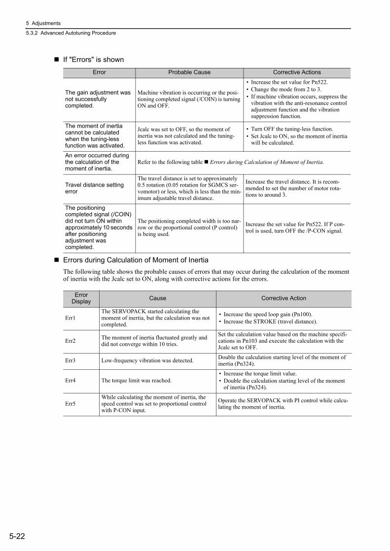
5 Adjustments
5.3.2 Advanced Autotuning Procedure
5-22
If "Errors" is shown
Errors during Calculation of Moment of InertiaThe following table shows the probable causes of errors that may occur during the calculation of the moment of inertia with the Jcalc set to ON, along with corrective actions for the errors.
Error Probable Cause Corrective Actions
The gain adjustment was not successfully completed.
Machine vibration is occurring or the posi-tioning completed signal (/COIN) is turning ON and OFF.
• Increase the set value for Pn522. • Change the mode from 2 to 3.• If machine vibration occurs, suppress the
vibration with the anti-resonance control adjustment function and the vibration suppression function.
The moment of inertia cannot be calculated when the tuning-less function was activated.
Jcalc was set to OFF, so the moment of inertia was not calculated and the tuning-less function was activated.
• Turn OFF the tuning-less function.• Set Jcalc to ON, so the moment of inertia
will be calculated.
An error occurred during the calculation of the moment of inertia.
Refer to the following table Errors during Calculation of Moment of Inertia.
Travel distance setting error
The travel distance is set to approximately 0.5 rotation (0.05 rotation for SGMCS ser-vomotor) or less, which is less than the min-imum adjustable travel distance.
Increase the travel distance. It is recom-mended to set the number of motor rota-tions to around 3.
The positioning completed signal (/COIN) did not turn ON within approximately 10 seconds after positioning adjustment was completed.
The positioning completed width is too nar-row or the proportional control (P control) is being used.
Increase the set value for Pn522. If P con-trol is used, turn OFF the /P-CON signal.
Error Display Cause Corrective Action
Err1The SERVOPACK started calculating the moment of inertia, but the calculation was not completed.
• Increase the speed loop gain (Pn100).• Increase the STROKE (travel distance).
Err2 The moment of inertia fluctuated greatly and did not converge within 10 tries.
Set the calculation value based on the machine specifi-cations in Pn103 and execute the calculation with the Jcalc set to OFF.
Err3 Low-frequency vibration was detected. Double the calculation starting level of the moment of inertia (Pn324).
Err4 The torque limit was reached.• Increase the torque limit value.• Double the calculation starting level of the moment
of inertia (Pn324).
Err5While calculating the moment of inertia, the speed control was set to proportional control with P-CON input.
Operate the SERVOPACK with PI control while calcu-lating the moment of inertia.
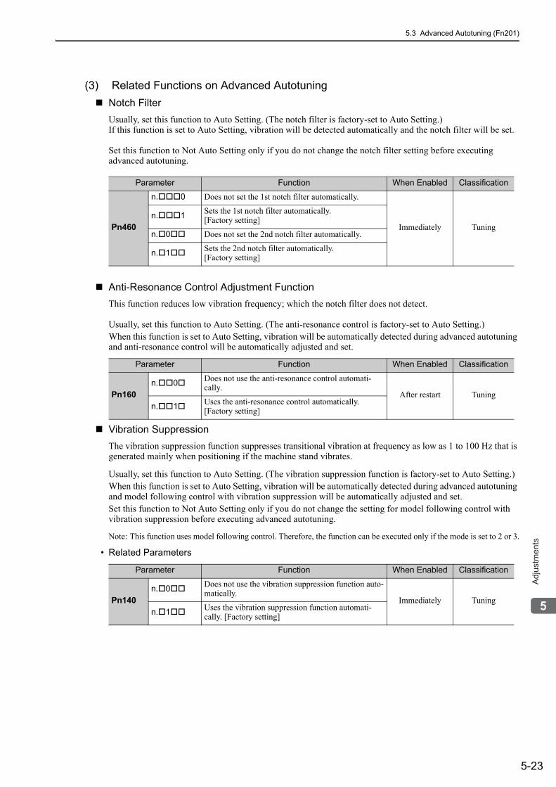
5.3 Advanced Autotuning (Fn201)
5-23
5
Ad
justm
en
ts
(3) Related Functions on Advanced AutotuningNotch FilterUsually, set this function to Auto Setting. (The notch filter is factory-set to Auto Setting.)If this function is set to Auto Setting, vibration will be detected automatically and the notch filter will be set.
Set this function to Not Auto Setting only if you do not change the notch filter setting before executing advanced autotuning.
Anti-Resonance Control Adjustment FunctionThis function reduces low vibration frequency; which the notch filter does not detect.
Usually, set this function to Auto Setting. (The anti-resonance control is factory-set to Auto Setting.)When this function is set to Auto Setting, vibration will be automatically detected during advanced autotuning and anti-resonance control will be automatically adjusted and set.
Vibration SuppressionThe vibration suppression function suppresses transitional vibration at frequency as low as 1 to 100 Hz that is generated mainly when positioning if the machine stand vibrates.
Usually, set this function to Auto Setting. (The vibration suppression function is factory-set to Auto Setting.)When this function is set to Auto Setting, vibration will be automatically detected during advanced autotuning and model following control with vibration suppression will be automatically adjusted and set.Set this function to Not Auto Setting only if you do not change the setting for model following control with vibration suppression before executing advanced autotuning.
Note: This function uses model following control. Therefore, the function can be executed only if the mode is set to 2 or 3.
• Related Parameters
Parameter Function When Enabled Classification
Pn460
n. 0 Does not set the 1st notch filter automatically.
Immediately Tuningn. 1 Sets the 1st notch filter automatically.
[Factory setting]
n. 0 Does not set the 2nd notch filter automatically.
n. 1 Sets the 2nd notch filter automatically. [Factory setting]
Parameter Function When Enabled Classification
Pn160n. 0 Does not use the anti-resonance control automati-
cally.After restart Tuning
n. 1 Uses the anti-resonance control automatically. [Factory setting]
Parameter Function When Enabled Classification
Pn140n. 0 Does not use the vibration suppression function auto-
matically.Immediately Tuning
n. 1 Uses the vibration suppression function automati-cally. [Factory setting]
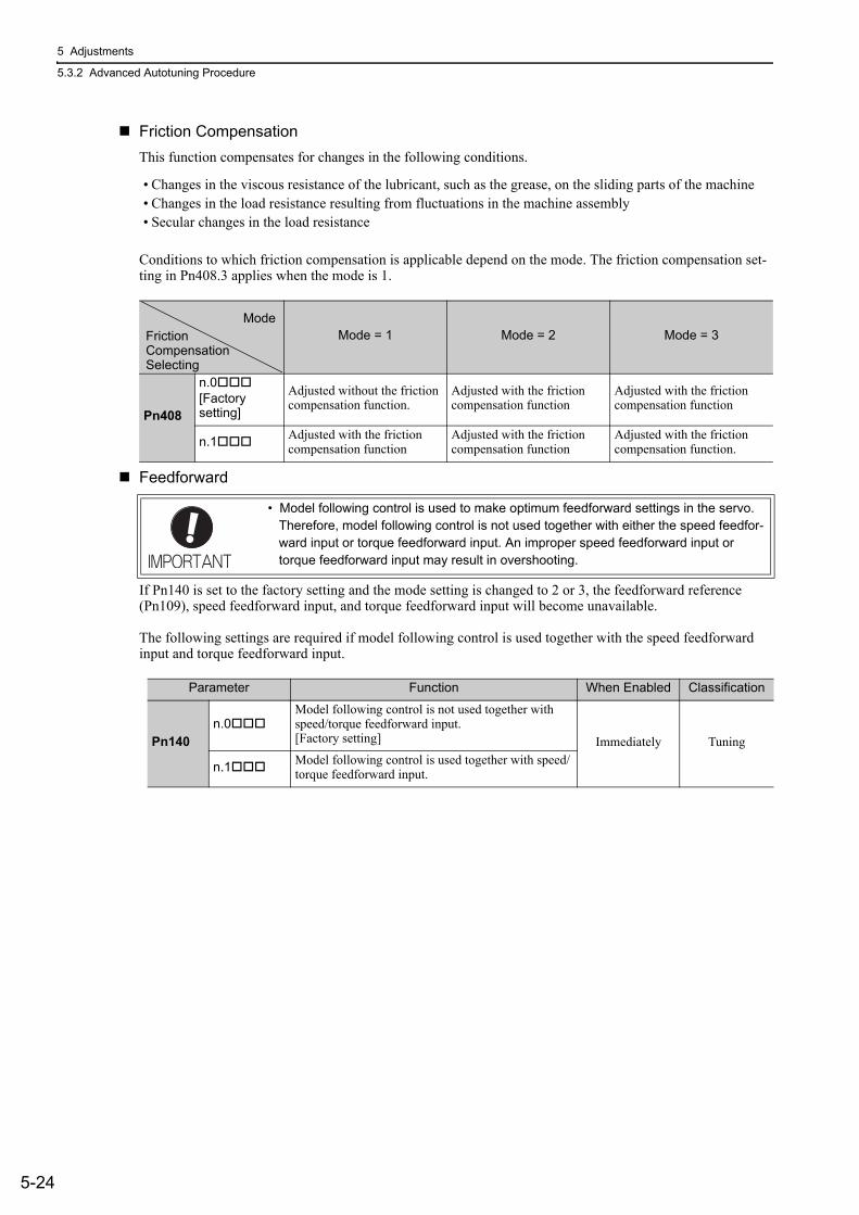
5 Adjustments
5.3.2 Advanced Autotuning Procedure
5-24
Friction CompensationThis function compensates for changes in the following conditions.
• Changes in the viscous resistance of the lubricant, such as the grease, on the sliding parts of the machine• Changes in the load resistance resulting from fluctuations in the machine assembly• Secular changes in the load resistance
Conditions to which friction compensation is applicable depend on the mode. The friction compensation set-ting in Pn408.3 applies when the mode is 1.
Feedforward
If Pn140 is set to the factory setting and the mode setting is changed to 2 or 3, the feedforward reference (Pn109), speed feedforward input, and torque feedforward input will become unavailable.
The following settings are required if model following control is used together with the speed feedforward input and torque feedforward input.
Mode = 1 Mode = 2 Mode = 3
Pn408
n.0[Factory setting]
Adjusted without the friction compensation function.
Adjusted with the friction compensation function
Adjusted with the friction compensation function
n.1 Adjusted with the friction compensation function
Adjusted with the friction compensation function
Adjusted with the friction compensation function.
ModeFrictionCompensationSelecting
• Model following control is used to make optimum feedforward settings in the servo. Therefore, model following control is not used together with either the speed feedfor-ward input or torque feedforward input. An improper speed feedforward input or torque feedforward input may result in overshooting.
Parameter Function When Enabled Classification
Pn140n.0
Model following control is not used together with speed/torque feedforward input.[Factory setting] Immediately Tuning
n.1 Model following control is used together with speed/torque feedforward input.
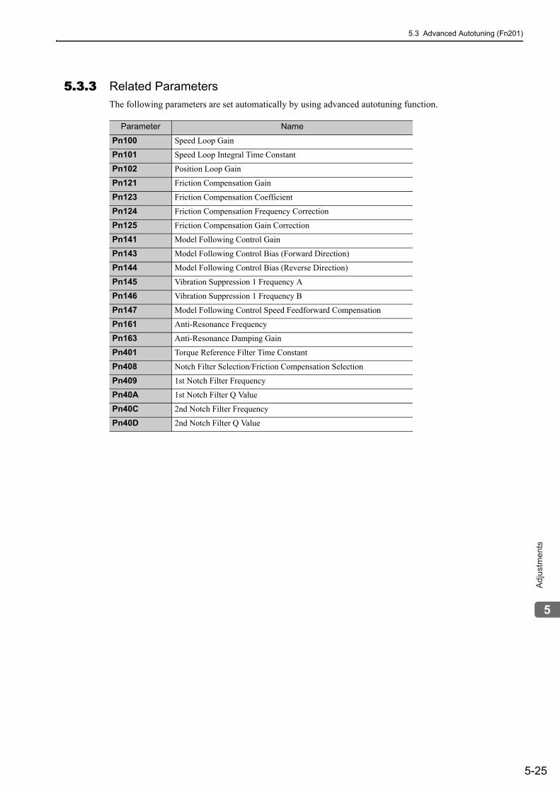
5.3 Advanced Autotuning (Fn201)
5-25
5
Ad
justm
en
ts
5.3.3 Related ParametersThe following parameters are set automatically by using advanced autotuning function.
Parameter Name
Pn100 Speed Loop Gain
Pn101 Speed Loop Integral Time Constant
Pn102 Position Loop Gain
Pn121 Friction Compensation Gain
Pn123 Friction Compensation Coefficient
Pn124 Friction Compensation Frequency Correction
Pn125 Friction Compensation Gain Correction
Pn141 Model Following Control Gain
Pn143 Model Following Control Bias (Forward Direction)
Pn144 Model Following Control Bias (Reverse Direction)
Pn145 Vibration Suppression 1 Frequency A
Pn146 Vibration Suppression 1 Frequency B
Pn147 Model Following Control Speed Feedforward Compensation
Pn161 Anti-Resonance Frequency
Pn163 Anti-Resonance Damping Gain
Pn401 Torque Reference Filter Time Constant
Pn408 Notch Filter Selection/Friction Compensation Selection
Pn409 1st Notch Filter Frequency
Pn40A 1st Notch Filter Q Value
Pn40C 2nd Notch Filter Frequency
Pn40D 2nd Notch Filter Q Value
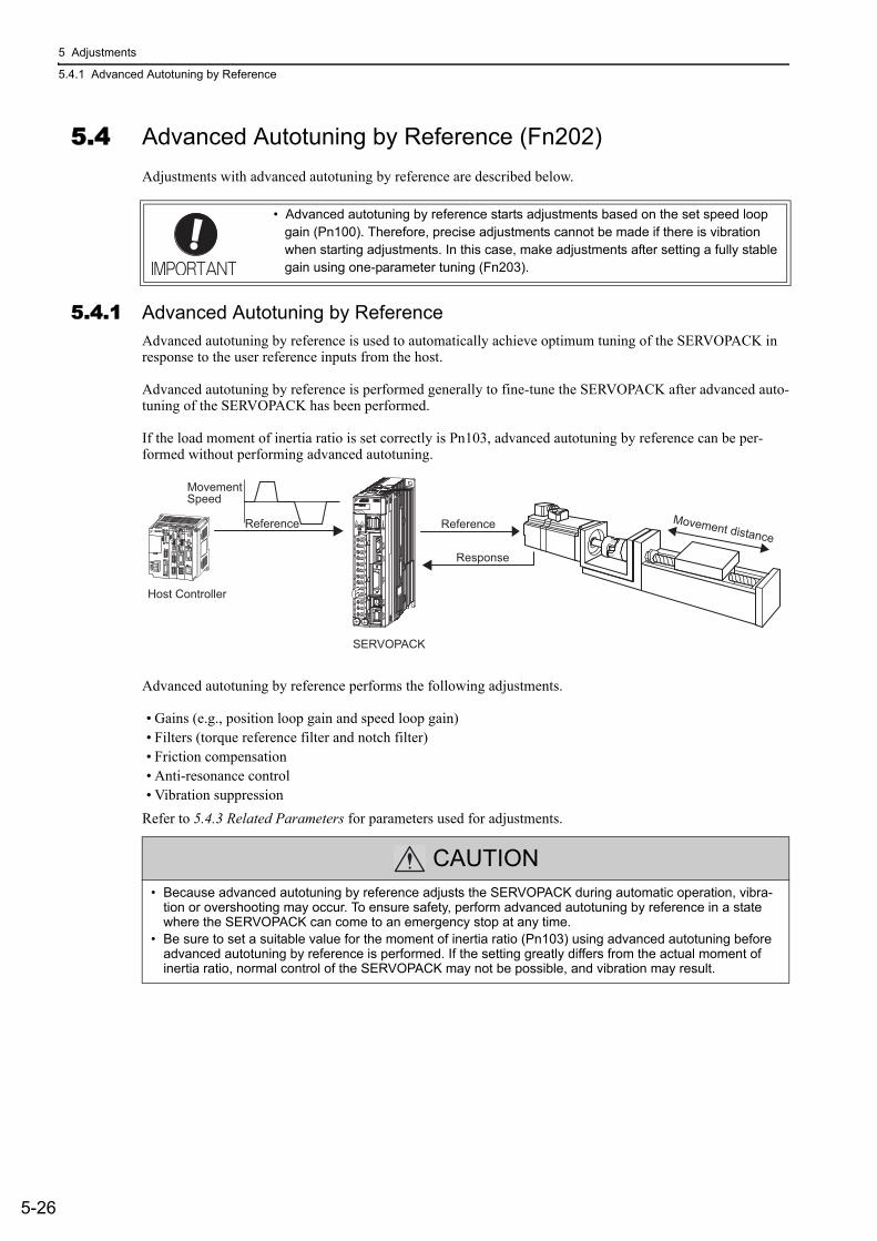
5 Adjustments
5.4.1 Advanced Autotuning by Reference
5-26
5.4 Advanced Autotuning by Reference (Fn202)Adjustments with advanced autotuning by reference are described below.
5.4.1 Advanced Autotuning by ReferenceAdvanced autotuning by reference is used to automatically achieve optimum tuning of the SERVOPACK in response to the user reference inputs from the host.
Advanced autotuning by reference is performed generally to fine-tune the SERVOPACK after advanced auto-tuning of the SERVOPACK has been performed.
If the load moment of inertia ratio is set correctly is Pn103, advanced autotuning by reference can be per-formed without performing advanced autotuning.
Advanced autotuning by reference performs the following adjustments.
• Gains (e.g., position loop gain and speed loop gain)• Filters (torque reference filter and notch filter)• Friction compensation• Anti-resonance control• Vibration suppression
Refer to 5.4.3 Related Parameters for parameters used for adjustments.
• Advanced autotuning by reference starts adjustments based on the set speed loop gain (Pn100). Therefore, precise adjustments cannot be made if there is vibration when starting adjustments. In this case, make adjustments after setting a fully stable gain using one-parameter tuning (Fn203).
CAUTION• Because advanced autotuning by reference adjusts the SERVOPACK during automatic operation, vibra-
tion or overshooting may occur. To ensure safety, perform advanced autotuning by reference in a state where the SERVOPACK can come to an emergency stop at any time.
• Be sure to set a suitable value for the moment of inertia ratio (Pn103) using advanced autotuning before advanced autotuning by reference is performed. If the setting greatly differs from the actual moment of inertia ratio, normal control of the SERVOPACK may not be possible, and vibration may result.
SERVOPACK
MovementSpeed
Host Controller
Reference
Response
Movement distanceReference
5.4 Advanced Autotuning by Reference (Fn202)
5-27
5
Ad
justm
en
ts
(1) Before Performing Advanced Autotuning by ReferenceCheck the following settings before performing advanced autotuning by reference.
a) A message (NO-OP) indicating that no operations are possible will be displayed, if all of the following conditions are not met.
• The main circuit power supply must be ON.• The servomotor power must be OFF.• The forward run prohibited (P-OT) and the reverse run prohibited (N-OT) signal must not be in an over-
travel state.• The position control must be selected while the servomotor power is ON.• The tuning-less function must be disabled.• Automatic gain switching must be disabled.• Gain setting 2 must not be selected.• Test without motor function must not be enabled. (Pn00C.0 = 0)• All alarms and warning must be cleared.• The hardwire baseblock (HWBB) must be off.b) Observe the following condition to ensure operation.• The write prohibited setting (Fn010) must not be set.
(2) When Advanced Autotuning by reference Cannot be AdjustedAdvanced autotuning by reference may not be performed normally under the following conditions. If the result of autotuning is not satisfactory, perform one-parameter tuning. Refer to 5.5 One-parameter Tuning (Fn203) for details.
• The travel distance in response to references from the host controller must be the same as or larger than the set positioning completed width (Pn522).
• The motor speed in response to references from the host controller must be the same as or larger than the set rotation detection level (Pn502).
• The stopping time, i.e., the period while the positioning completed /COIN signal is OFF, is 10 ms or longer.• The rigidity of the load is low and vibration occurs when positioning is performed.• The position integration function is used.• P control operation (proportional control) is performed.• The mode switch is used.• The positioning completed width is to small.
• Advanced autotuning by reference starts adjustments based on the positioning com-pleted width (Pn522). Set the electronic gear ratio (Pn20E/Pn210) and positioning completed width (Pn522) to the actual value during operation.
• Unless the positioning completed signal (/COIN) is turned ON within approximately 3 seconds after positioning has been completed, "WAITING" will blink. Furthermore, unless the positioning completed signal (/COIN) is turned ON within approximately 10 seconds, "Error" will blink for 2 seconds and tuning will be aborted.
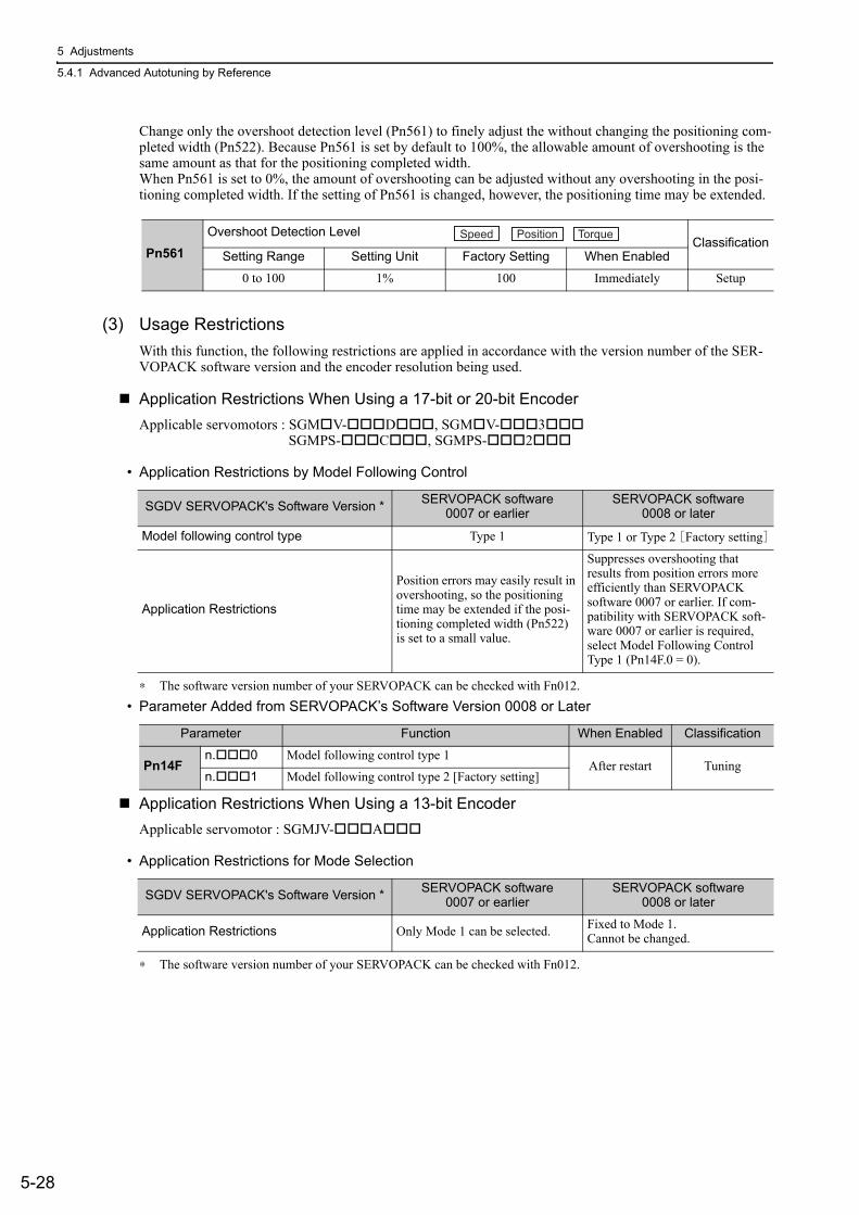
5 Adjustments
5.4.1 Advanced Autotuning by Reference
5-28
Change only the overshoot detection level (Pn561) to finely adjust the without changing the positioning com-pleted width (Pn522). Because Pn561 is set by default to 100%, the allowable amount of overshooting is the same amount as that for the positioning completed width. When Pn561 is set to 0%, the amount of overshooting can be adjusted without any overshooting in the posi-tioning completed width. If the setting of Pn561 is changed, however, the positioning time may be extended.
(3) Usage RestrictionsWith this function, the following restrictions are applied in accordance with the version number of the SER-VOPACK software version and the encoder resolution being used.
Application Restrictions When Using a 17-bit or 20-bit EncoderApplicable servomotors : SGM V- D , SGM V- 3
SGMPS- C , SGMPS- 2
• Application Restrictions by Model Following Control
∗ The software version number of your SERVOPACK can be checked with Fn012.• Parameter Added from SERVOPACK’s Software Version 0008 or Later
Application Restrictions When Using a 13-bit EncoderApplicable servomotor : SGMJV- A
• Application Restrictions for Mode Selection
∗ The software version number of your SERVOPACK can be checked with Fn012.
Pn561Overshoot Detection Level
ClassificationSetting Range Setting Unit Factory Setting When Enabled
0 to 100 1% 100 Immediately Setup
Speed Position Torque
SGDV SERVOPACK's Software Version * SERVOPACK software0007 or earlier
SERVOPACK software0008 or later
Model following control type Type 1 Type 1 or Type 2 [Factory setting]
Application Restrictions
Position errors may easily result in overshooting, so the positioning time may be extended if the posi-tioning completed width (Pn522) is set to a small value.
Suppresses overshooting that results from position errors more efficiently than SERVOPACK software 0007 or earlier. If com-patibility with SERVOPACK soft-ware 0007 or earlier is required, select Model Following Control Type 1 (Pn14F.0 = 0).
Parameter Function When Enabled Classification
Pn14Fn. 0 Model following control type 1
After restart Tuningn. 1 Model following control type 2 [Factory setting]
SGDV SERVOPACK's Software Version * SERVOPACK software 0007 or earlier
SERVOPACK software 0008 or later
Application Restrictions Only Mode 1 can be selected. Fixed to Mode 1.Cannot be changed.
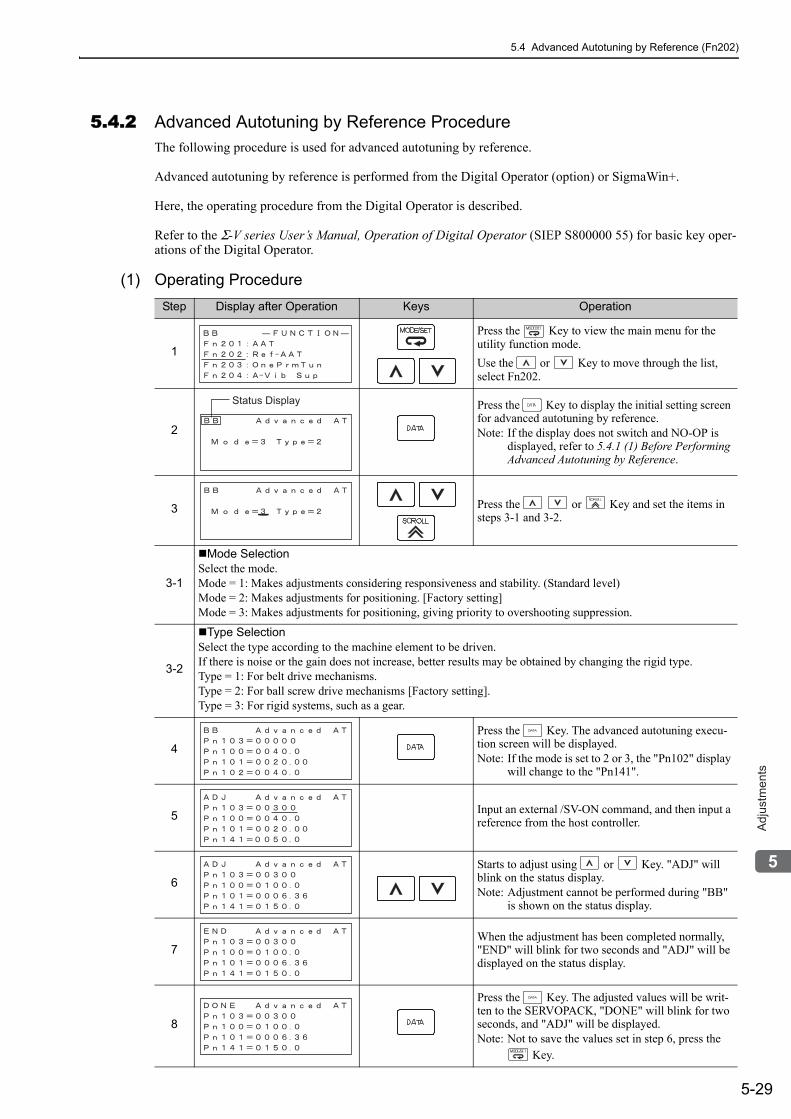
5.4 Advanced Autotuning by Reference (Fn202)
5-29
5
Ad
justm
en
ts
5.4.2 Advanced Autotuning by Reference Procedure The following procedure is used for advanced autotuning by reference.
Advanced autotuning by reference is performed from the Digital Operator (option) or SigmaWin+.
Here, the operating procedure from the Digital Operator is described.
Refer to the Σ-V series User’s Manual, Operation of Digital Operator (SIEP S800000 55) for basic key oper-ations of the Digital Operator.
(1) Operating ProcedureStep Display after Operation Keys Operation
1
Press the Key to view the main menu for the utility function mode.Use the or Key to move through the list, select Fn202.
2
Press the Key to display the initial setting screen for advanced autotuning by reference.Note: If the display does not switch and NO-OP is
displayed, refer to 5.4.1 (1) Before Performing Advanced Autotuning by Reference.
3 Press the or Key and set the items in steps 3-1 and 3-2.
3-1
Mode SelectionSelect the mode.Mode = 1: Makes adjustments considering responsiveness and stability. (Standard level)Mode = 2: Makes adjustments for positioning. [Factory setting]Mode = 3: Makes adjustments for positioning, giving priority to overshooting suppression.
3-2
Type SelectionSelect the type according to the machine element to be driven.If there is noise or the gain does not increase, better results may be obtained by changing the rigid type.Type = 1: For belt drive mechanisms.Type = 2: For ball screw drive mechanisms [Factory setting].Type = 3: For rigid systems, such as a gear.
4Press the Key. The advanced autotuning execu-tion screen will be displayed.Note: If the mode is set to 2 or 3, the "Pn102" display
will change to the "Pn141".
5 Input an external /SV-ON command, and then input a reference from the host controller.
6Starts to adjust using or Key. "ADJ" will blink on the status display.Note: Adjustment cannot be performed during "BB"
is shown on the status display.
7When the adjustment has been completed normally, "END" will blink for two seconds and "ADJ" will be displayed on the status display.
8
Press the Key. The adjusted values will be writ-ten to the SERVOPACK, "DONE" will blink for two seconds, and "ADJ" will be displayed. Note: Not to save the values set in step 6, press the
Key.
Status Display
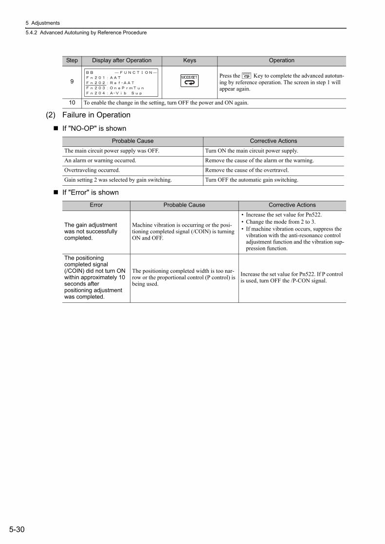
5 Adjustments
5.4.2 Advanced Autotuning by Reference Procedure
5-30
(2) Failure in Operation
If "NO-OP" is shown
If "Error" is shown
9Press the Key to complete the advanced autotun-ing by reference operation. The screen in step 1 will appear again.
10 To enable the change in the setting, turn OFF the power and ON again.
Probable Cause Corrective Actions
The main circuit power supply was OFF. Turn ON the main circuit power supply.
An alarm or warning occurred. Remove the cause of the alarm or the warning.
Overtraveling occurred. Remove the cause of the overtravel.
Gain setting 2 was selected by gain switching. Turn OFF the automatic gain switching.
Error Probable Cause Corrective Actions
The gain adjustment was not successfully completed.
Machine vibration is occurring or the posi-tioning completed signal (/COIN) is turning ON and OFF.
• Increase the set value for Pn522.• Change the mode from 2 to 3.• If machine vibration occurs, suppress the
vibration with the anti-resonance control adjustment function and the vibration sup-pression function.
The positioning completed signal (/COIN) did not turn ON within approximately 10 seconds after positioning adjustment was completed.
The positioning completed width is too nar-row or the proportional control (P control) is being used.
Increase the set value for Pn522. If P control is used, turn OFF the /P-CON signal.
Step Display after Operation Keys Operation
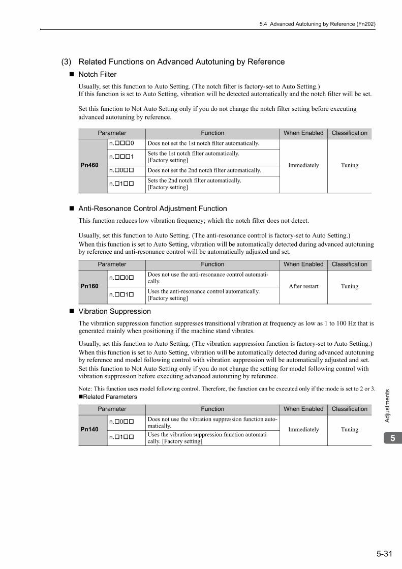
5.4 Advanced Autotuning by Reference (Fn202)
5-31
5
Ad
justm
en
ts
(3) Related Functions on Advanced Autotuning by ReferenceNotch FilterUsually, set this function to Auto Setting. (The notch filter is factory-set to Auto Setting.)If this function is set to Auto Setting, vibration will be detected automatically and the notch filter will be set.
Set this function to Not Auto Setting only if you do not change the notch filter setting before executing advanced autotuning by reference.
Anti-Resonance Control Adjustment FunctionThis function reduces low vibration frequency; which the notch filter does not detect.
Usually, set this function to Auto Setting. (The anti-resonance control is factory-set to Auto Setting.)When this function is set to Auto Setting, vibration will be automatically detected during advanced autotuning by reference and anti-resonance control will be automatically adjusted and set.
Vibration SuppressionThe vibration suppression function suppresses transitional vibration at frequency as low as 1 to 100 Hz that is generated mainly when positioning if the machine stand vibrates.
Usually, set this function to Auto Setting. (The vibration suppression function is factory-set to Auto Setting.)When this function is set to Auto Setting, vibration will be automatically detected during advanced autotuning by reference and model following control with vibration suppression will be automatically adjusted and set.Set this function to Not Auto Setting only if you do not change the setting for model following control with vibration suppression before executing advanced autotuning by reference.
Note: This function uses model following control. Therefore, the function can be executed only if the mode is set to 2 or 3.Related Parameters
Parameter Function When Enabled Classification
Pn460
n. 0 Does not set the 1st notch filter automatically.
Immediately Tuningn. 1 Sets the 1st notch filter automatically.
[Factory setting]
n. 0 Does not set the 2nd notch filter automatically.
n. 1 Sets the 2nd notch filter automatically. [Factory setting]
Parameter Function When Enabled Classification
Pn160n. 0 Does not use the anti-resonance control automati-
cally.After restart Tuning
n. 1 Uses the anti-resonance control automatically. [Factory setting]
Parameter Function When Enabled Classification
Pn140n. 0 Does not use the vibration suppression function auto-
matically. Immediately Tuningn. 1 Uses the vibration suppression function automati-
cally. [Factory setting]
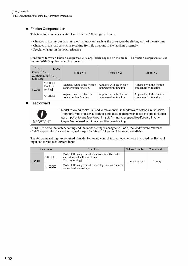
5 Adjustments
5.4.2 Advanced Autotuning by Reference Procedure
5-32
Friction CompensationThis function compensates for changes in the following conditions.
• Changes in the viscous resistance of the lubricant, such as the grease, on the sliding parts of the machine• Changes in the load resistance resulting from fluctuations in the machine assembly• Secular changes in the load resistance
Conditions to which friction compensation is applicable depend on the mode. The friction compensation set-ting in Pn408.3 applies when the mode is 1.
Feedforward
If Pn140 is set to the factory setting and the mode setting is changed to 2 or 3, the feedforward reference (Pn109), speed feedforward input, and torque feedforward input will become unavailable.
The following settings are required if model following control is used together with the speed feedforward input and torque feedforward input.
Mode = 1 Mode = 2 Mode = 3
Pn408
n.0[Factory setting]
Adjusted without the friction compensation function.
Adjusted with the friction compensation function.
Adjusted with the friction compensation function.
n.1 Adjusted with the friction compensation function.
Adjusted with the friction compensation function.
Adjusted with the friction compensation function.
• Model following control is used to make optimum feedforward settings in the servo. Therefore, model following control is not used together with either the speed feedfor-ward input or torque feedforward input. An improper speed feedforward input or torque feedforward input may result in overshooting.
ModeFrictionCompensationSelecting
Parameter Function When Enabled Classification
Pn140n.0
Model following control is not used together with speed/torque feedforward input. [Factory setting] Immediately Tuning
n.1 Model following control is used together with speed/torque feedforward input.
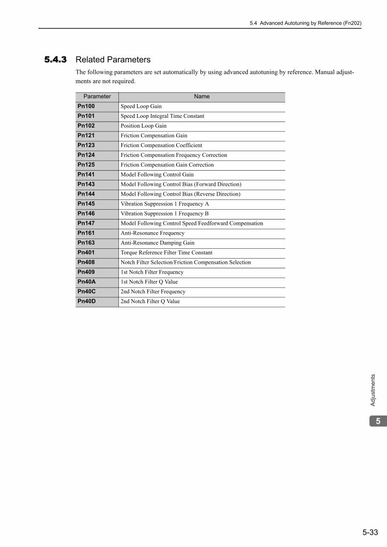
5.4 Advanced Autotuning by Reference (Fn202)
5-33
5
Ad
justm
en
ts
5.4.3 Related ParametersThe following parameters are set automatically by using advanced autotuning by reference. Manual adjust-ments are not required.
Parameter Name
Pn100 Speed Loop Gain
Pn101 Speed Loop Integral Time Constant
Pn102 Position Loop Gain
Pn121 Friction Compensation Gain
Pn123 Friction Compensation Coefficient
Pn124 Friction Compensation Frequency Correction
Pn125 Friction Compensation Gain Correction
Pn141 Model Following Control Gain
Pn143 Model Following Control Bias (Forward Direction)
Pn144 Model Following Control Bias (Reverse Direction)
Pn145 Vibration Suppression 1 Frequency A
Pn146 Vibration Suppression 1 Frequency B
Pn147 Model Following Control Speed Feedforward Compensation
Pn161 Anti-Resonance Frequency
Pn163 Anti-Resonance Damping Gain
Pn401 Torque Reference Filter Time Constant
Pn408 Notch Filter Selection/Friction Compensation Selection
Pn409 1st Notch Filter Frequency
Pn40A 1st Notch Filter Q Value
Pn40C 2nd Notch Filter Frequency
Pn40D 2nd Notch Filter Q Value
5 Adjustments
5.5.1 One-parameter Tuning
5-34
5.5 One-parameter Tuning (Fn203)Adjustments with one-parameter tuning are described below.
5.5.1 One-parameter TuningOne-parameter tuning is used to manually make tuning level adjustments during operation with a position ref-erence or speed reference input from the host controller.
One-parameter tuning enables automatically setting related servo gain settings to balanced conditions by adjusting one or two autotuning levels.
One-parameter tuning performs the following adjustments.
• Gains (e.g., position loop gain and speed loop gain)• Filters (torque reference filter and notch filter)• Friction compensation• Anti-resonance control
Refer to 5.5.4 Related Parameters for parameters used for adjustments.
Perform one-parameter tuning if satisfactory responsiveness is not obtained with advanced autotuning or advanced autotuning by reference.
To fine-tune each servo gain after one-parameter tuning, refer to 5.8 Additional Adjustment Function.
CAUTION• Vibration or overshooting may occur during adjustment. To ensure safety, perform one-parameter tuning in
a state where the SERVOPACK can come to an emergency stop at any time.• Be sure to set a suitable value for the moment of inertia ratio (Pn103) using advanced autotuning before
one-parameter tuning is performed. If the setting greatly differs from the actual moment of inertia ratio, nor-mal control of the SERVOPACK may not be possible, and vibration may result.
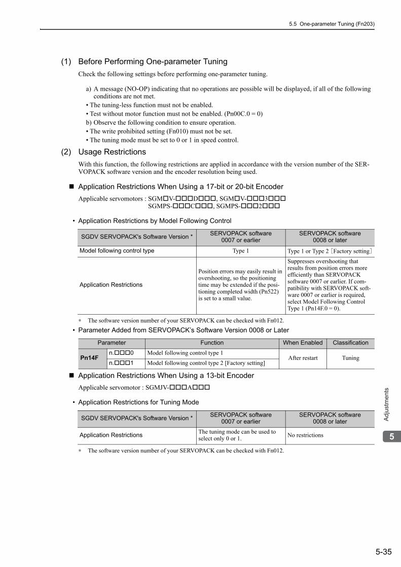
5.5 One-parameter Tuning (Fn203)
5-35
5
Ad
justm
en
ts
(1) Before Performing One-parameter TuningCheck the following settings before performing one-parameter tuning.
a) A message (NO-OP) indicating that no operations are possible will be displayed, if all of the following conditions are not met.
• The tuning-less function must not be enabled.• Test without motor function must not be enabled. (Pn00C.0 = 0)b) Observe the following condition to ensure operation.• The write prohibited setting (Fn010) must not be set.• The tuning mode must be set to 0 or 1 in speed control.
(2) Usage RestrictionsWith this function, the following restrictions are applied in accordance with the version number of the SER-VOPACK software version and the encoder resolution being used.
Application Restrictions When Using a 17-bit or 20-bit EncoderApplicable servomotors : SGM V- D , SGM V- 3
SGMPS- C , SGMPS- 2
• Application Restrictions by Model Following Control
∗ The software version number of your SERVOPACK can be checked with Fn012.• Parameter Added from SERVOPACK’s Software Version 0008 or Later
Application Restrictions When Using a 13-bit EncoderApplicable servomotor : SGMJV- A
• Application Restrictions for Tuning Mode
∗ The software version number of your SERVOPACK can be checked with Fn012.
SGDV SERVOPACK's Software Version * SERVOPACK software0007 or earlier
SERVOPACK software0008 or later
Model following control type Type 1 Type 1 or Type 2 [Factory setting]
Application Restrictions
Position errors may easily result in overshooting, so the positioning time may be extended if the posi-tioning completed width (Pn522) is set to a small value.
Suppresses overshooting that results from position errors more efficiently than SERVOPACK software 0007 or earlier. If com-patibility with SERVOPACK soft-ware 0007 or earlier is required, select Model Following Control Type 1 (Pn14F.0 = 0).
Parameter Function When Enabled Classification
Pn14Fn. 0 Model following control type 1
After restart Tuningn. 1 Model following control type 2 [Factory setting]
SGDV SERVOPACK's Software Version * SERVOPACK software0007 or earlier
SERVOPACK software0008 or later
Application Restrictions The tuning mode can be used to select only 0 or 1. No restrictions
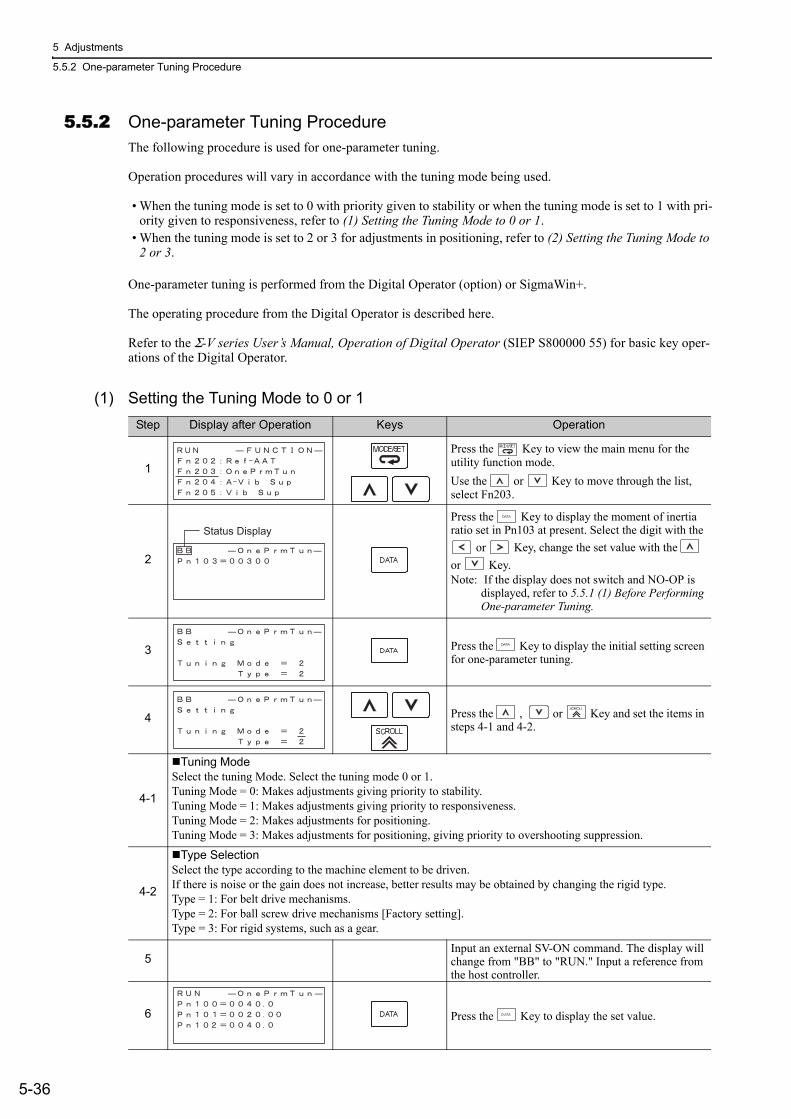
5 Adjustments
5.5.2 One-parameter Tuning Procedure
5-36
5.5.2 One-parameter Tuning ProcedureThe following procedure is used for one-parameter tuning.
Operation procedures will vary in accordance with the tuning mode being used.
• When the tuning mode is set to 0 with priority given to stability or when the tuning mode is set to 1 with pri-ority given to responsiveness, refer to (1) Setting the Tuning Mode to 0 or 1.
• When the tuning mode is set to 2 or 3 for adjustments in positioning, refer to (2) Setting the Tuning Mode to 2 or 3.
One-parameter tuning is performed from the Digital Operator (option) or SigmaWin+.
The operating procedure from the Digital Operator is described here.
Refer to the Σ-V series User’s Manual, Operation of Digital Operator (SIEP S800000 55) for basic key oper-ations of the Digital Operator.
(1) Setting the Tuning Mode to 0 or 1Step Display after Operation Keys Operation
1
Press the Key to view the main menu for the utility function mode.Use the or Key to move through the list, select Fn203.
2
Press the Key to display the moment of inertia ratio set in Pn103 at present. Select the digit with the
or Key, change the set value with the or Key.Note: If the display does not switch and NO-OP is
displayed, refer to 5.5.1 (1) Before Performing One-parameter Tuning.
3 Press the Key to display the initial setting screen for one-parameter tuning.
4 Press the , or Key and set the items in steps 4-1 and 4-2.
4-1
Tuning ModeSelect the tuning Mode. Select the tuning mode 0 or 1.Tuning Mode = 0: Makes adjustments giving priority to stability.Tuning Mode = 1: Makes adjustments giving priority to responsiveness.Tuning Mode = 2: Makes adjustments for positioning.Tuning Mode = 3: Makes adjustments for positioning, giving priority to overshooting suppression.
4-2
Type SelectionSelect the type according to the machine element to be driven. If there is noise or the gain does not increase, better results may be obtained by changing the rigid type.Type = 1: For belt drive mechanisms.Type = 2: For ball screw drive mechanisms [Factory setting].Type = 3: For rigid systems, such as a gear.
5Input an external SV-ON command. The display will change from "BB" to "RUN." Input a reference from the host controller.
6 Press the Key to display the set value.
Status Display
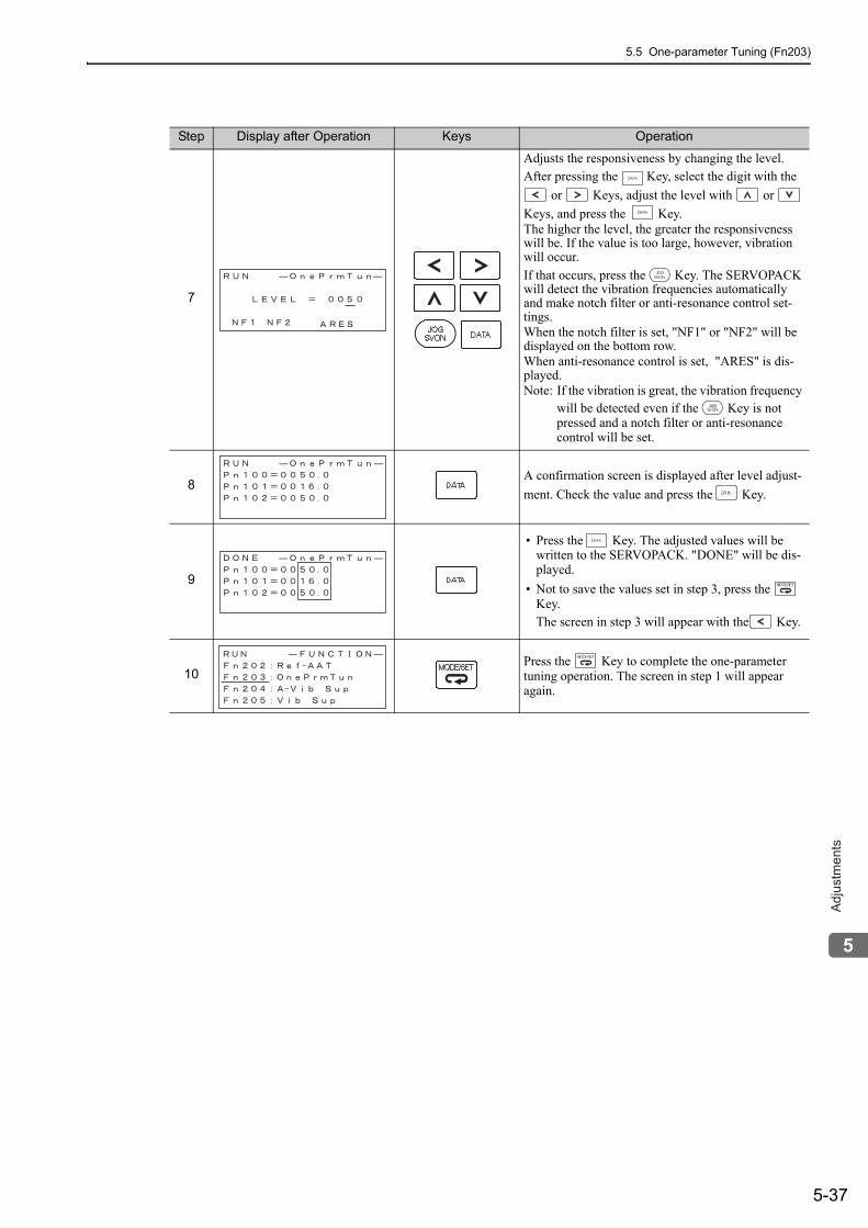
5.5 One-parameter Tuning (Fn203)
5-37
5
Ad
justm
en
ts
7
Adjusts the responsiveness by changing the level. After pressing the Key, select the digit with the
or Keys, adjust the level with or Keys, and press the Key.The higher the level, the greater the responsiveness will be. If the value is too large, however, vibration will occur. If that occurs, press the Key. The SERVOPACK will detect the vibration frequencies automatically and make notch filter or anti-resonance control set-tings.When the notch filter is set, "NF1" or "NF2" will be displayed on the bottom row. When anti-resonance control is set, "ARES" is dis-played.Note: If the vibration is great, the vibration frequency
will be detected even if the Key is not pressed and a notch filter or anti-resonance control will be set.
8A confirmation screen is displayed after level adjust-ment. Check the value and press the Key.
9
• Press the Key. The adjusted values will be written to the SERVOPACK. "DONE" will be dis-played.
• Not to save the values set in step 3, press the Key.The screen in step 3 will appear with the Key.
10Press the Key to complete the one-parameter tuning operation. The screen in step 1 will appear again.
Step Display after Operation Keys Operation
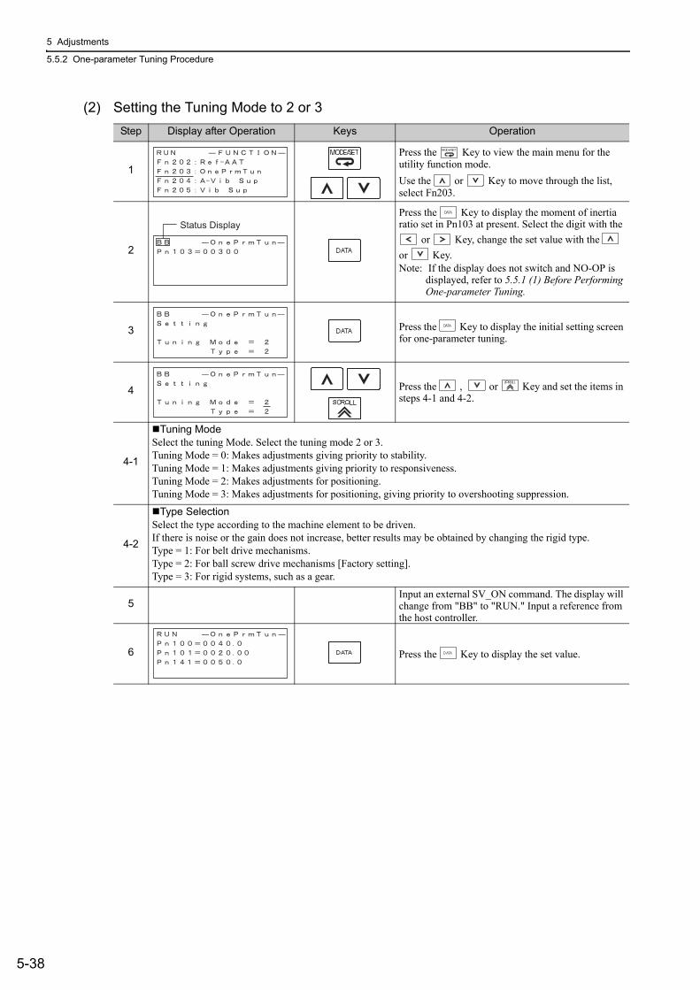
5 Adjustments
5.5.2 One-parameter Tuning Procedure
5-38
(2) Setting the Tuning Mode to 2 or 3Step Display after Operation Keys Operation
1
Press the Key to view the main menu for the utility function mode.Use the or Key to move through the list, select Fn203.
2
Press the Key to display the moment of inertia ratio set in Pn103 at present. Select the digit with the
or Key, change the set value with the or Key.Note: If the display does not switch and NO-OP is
displayed, refer to 5.5.1 (1) Before Performing One-parameter Tuning.
3 Press the Key to display the initial setting screen for one-parameter tuning.
4 Press the , or Key and set the items in steps 4-1 and 4-2.
4-1
Tuning ModeSelect the tuning Mode. Select the tuning mode 2 or 3.Tuning Mode = 0: Makes adjustments giving priority to stability.Tuning Mode = 1: Makes adjustments giving priority to responsiveness.Tuning Mode = 2: Makes adjustments for positioning.Tuning Mode = 3: Makes adjustments for positioning, giving priority to overshooting suppression.
4-2
Type SelectionSelect the type according to the machine element to be driven.If there is noise or the gain does not increase, better results may be obtained by changing the rigid type.Type = 1: For belt drive mechanisms.Type = 2: For ball screw drive mechanisms [Factory setting].Type = 3: For rigid systems, such as a gear.
5Input an external SV_ON command. The display will change from "BB" to "RUN." Input a reference from the host controller.
6 Press the Key to display the set value.
Status Display
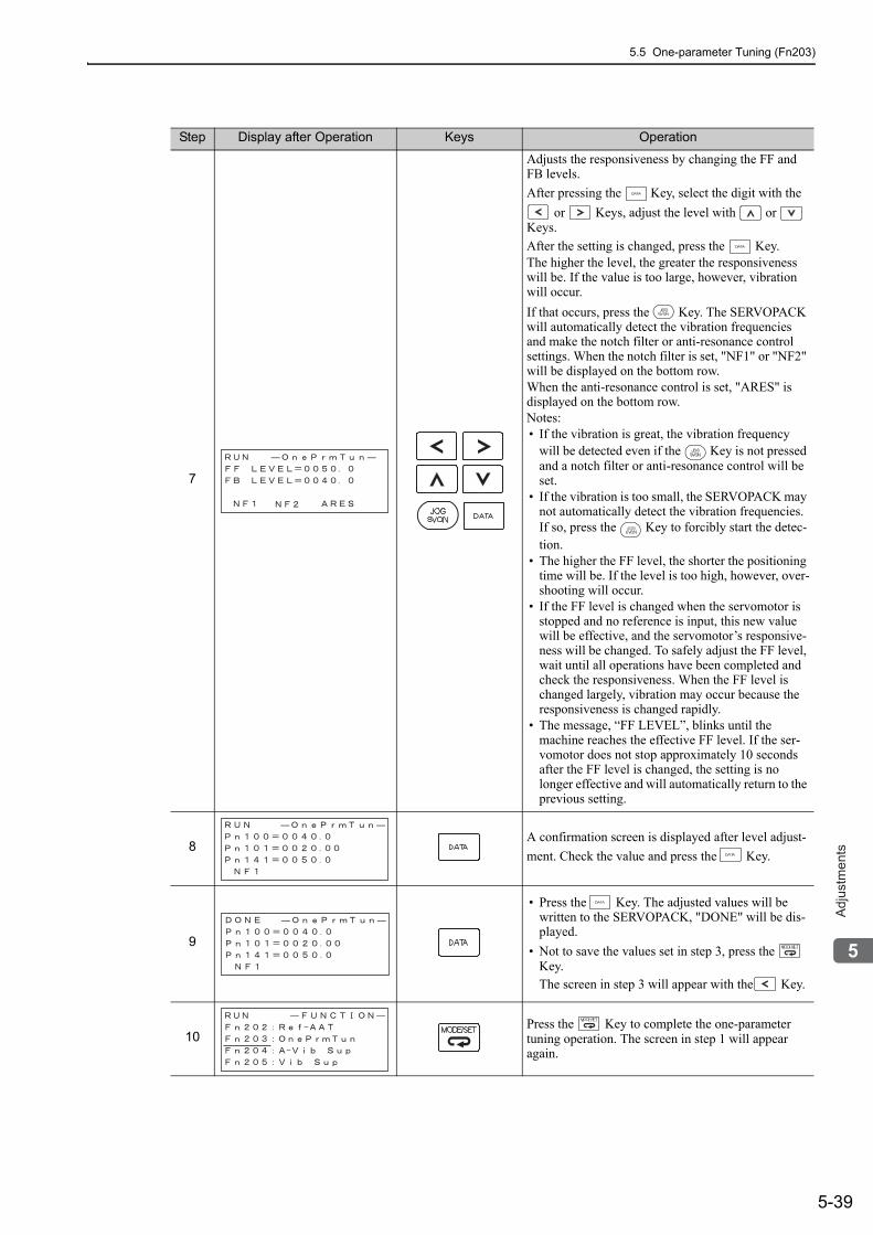
5.5 One-parameter Tuning (Fn203)
5-39
5
Ad
justm
en
ts
7
Adjusts the responsiveness by changing the FF and FB levels.After pressing the Key, select the digit with the
or Keys, adjust the level with or Keys.After the setting is changed, press the Key.The higher the level, the greater the responsiveness will be. If the value is too large, however, vibration will occur.If that occurs, press the Key. The SERVOPACK will automatically detect the vibration frequencies and make the notch filter or anti-resonance control settings. When the notch filter is set, "NF1" or "NF2" will be displayed on the bottom row. When the anti-resonance control is set, "ARES" is displayed on the bottom row.Notes:• If the vibration is great, the vibration frequency
will be detected even if the Key is not pressed and a notch filter or anti-resonance control will be set.
• If the vibration is too small, the SERVOPACK may not automatically detect the vibration frequencies. If so, press the Key to forcibly start the detec-tion.
• The higher the FF level, the shorter the positioning time will be. If the level is too high, however, over-shooting will occur.
• If the FF level is changed when the servomotor is stopped and no reference is input, this new value will be effective, and the servomotor’s responsive-ness will be changed. To safely adjust the FF level, wait until all operations have been completed and check the responsiveness. When the FF level is changed largely, vibration may occur because the responsiveness is changed rapidly.
• The message, “FF LEVEL”, blinks until the machine reaches the effective FF level. If the ser-vomotor does not stop approximately 10 seconds after the FF level is changed, the setting is no longer effective and will automatically return to the previous setting.
8A confirmation screen is displayed after level adjust-ment. Check the value and press the Key.
9
• Press the Key. The adjusted values will be written to the SERVOPACK, "DONE" will be dis-played.
• Not to save the values set in step 3, press the Key.The screen in step 3 will appear with the Key.
10Press the Key to complete the one-parameter tuning operation. The screen in step 1 will appear again.
Step Display after Operation Keys Operation
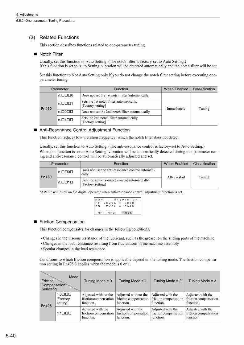
5 Adjustments
5.5.2 One-parameter Tuning Procedure
5-40
(3) Related Functions This section describes functions related to one-parameter tuning.
Notch FilterUsually, set this function to Auto Setting. (The notch filter is factory-set to Auto Setting.)If this function is set to Auto Setting, vibration will be detected automatically and the notch filter will be set.
Set this function to Not Auto Setting only if you do not change the notch filter setting before executing one-parameter tuning.
Anti-Resonance Control Adjustment FunctionThis function reduces low vibration frequency; which the notch filter does not detect.
Usually, set this function to Auto Setting. (The anti-resonance control is factory-set to Auto Setting.)When this function is set to Auto Setting, vibration will be automatically detected during one-parameter tun-ing and anti-resonance control will be automatically adjusted and set.
"ARES" will blink on the digital operator when anti-resonance control adjustment function is set.
Friction CompensationThis function compensates for changes in the following conditions.
• Changes in the viscous resistance of the lubricant, such as the grease, on the sliding parts of the machine• Changes in the load resistance resulting from fluctuations in the machine assembly• Secular changes in the load resistance
Conditions to which friction compensation is applicable depend on the tuning mode. The friction compensa-tion setting in Pn408.3 applies when the mode is 0 or 1.
Parameter Function When Enabled Classification
Pn460
n. 0 Does not set the 1st notch filter automatically.
Immediately Tuningn. 1 Sets the 1st notch filter automatically.
[Factory setting]
n. 0 Does not set the 2nd notch filter automatically.
n. 1 Sets the 2nd notch filter automatically. [Factory setting]
Parameter Function When Enabled Classification
Pn160n. 0 Does not use the anti-resonance control automati-
cally.After restart Tuning
n. 1 Uses the anti-resonance control automatically.[Factory setting]
Tuning Mode = 0 Tuning Mode = 1 Tuning Mode = 2 Tuning Mode = 3
Pn408
n.0[Factory setting]
Adjusted without the friction compensation function.
Adjusted without the friction compensation function.
Adjusted with the friction compensation function.
Adjusted with the friction compensation function.
n.1Adjusted with the friction compensation function.
Adjusted with the friction compensation function.
Adjusted with the friction compensation function.
Adjusted with the friction compensation function.
ModeFrictionCompensationSelecting
5.5 One-parameter Tuning (Fn203)
5-41
5
Ad
justm
en
ts
Feedforward
If Pn140 is set to the factory setting and the mode setting is changed to 2 or 3, the feedforward reference (Pn109), speed feedforward input, and torque feedforward input will become unavailable.
Set Pn140.3 (4th digit of Pn140) to 1 if model following control is used together with one or both of the fol-lowing inputs;• Speed feedforward input• Torque feedforward input
• Model following control is used to make optimum feedforward settings in the servo. Therefore, model following control is not used together with either the speed feedfor-ward input or torque feedforward input. An improper speed feedforward input or torque feedforward input may result in overshooting.
Parameter Function When Enabled Classification
Pn140n.0
Model following control is not used together with speed/torque feedforward input.[Factory setting] Immediately Tuning
n.1 Model following control is used together with speed/torque feedforward input.
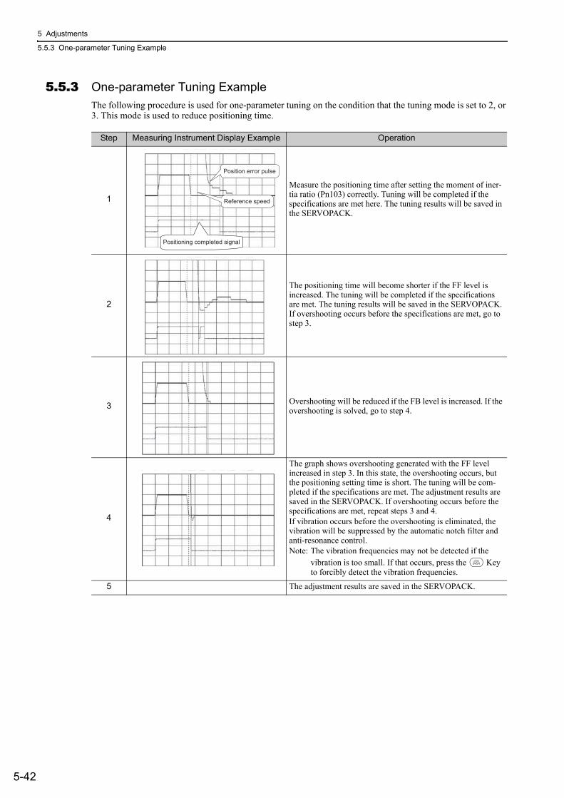
5 Adjustments
5.5.3 One-parameter Tuning Example
5-42
5.5.3 One-parameter Tuning ExampleThe following procedure is used for one-parameter tuning on the condition that the tuning mode is set to 2, or 3. This mode is used to reduce positioning time.
Step Measuring Instrument Display Example Operation
1
Measure the positioning time after setting the moment of iner-tia ratio (Pn103) correctly. Tuning will be completed if the specifications are met here. The tuning results will be saved in the SERVOPACK.
2
The positioning time will become shorter if the FF level is increased. The tuning will be completed if the specifications are met. The tuning results will be saved in the SERVOPACK. If overshooting occurs before the specifications are met, go to step 3.
3 Overshooting will be reduced if the FB level is increased. If the overshooting is solved, go to step 4.
4
The graph shows overshooting generated with the FF level increased in step 3. In this state, the overshooting occurs, but the positioning setting time is short. The tuning will be com-pleted if the specifications are met. The adjustment results are saved in the SERVOPACK. If overshooting occurs before the specifications are met, repeat steps 3 and 4.If vibration occurs before the overshooting is eliminated, the vibration will be suppressed by the automatic notch filter and anti-resonance control.Note: The vibration frequencies may not be detected if the
vibration is too small. If that occurs, press the Key to forcibly detect the vibration frequencies.
5 The adjustment results are saved in the SERVOPACK.
Positioning completed signal
Position error pulse
Reference speed
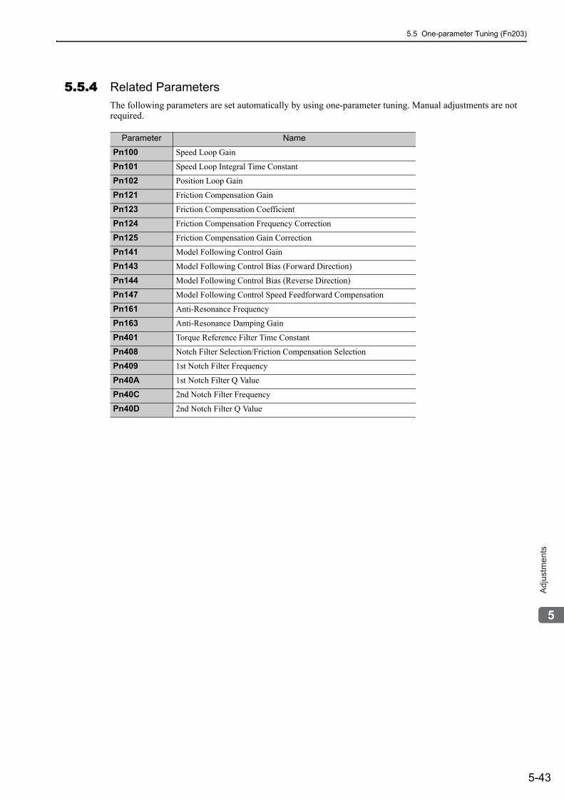
5.5 One-parameter Tuning (Fn203)
5-43
5
Ad
justm
en
ts
5.5.4 Related ParametersThe following parameters are set automatically by using one-parameter tuning. Manual adjustments are not required.
Parameter Name
Pn100 Speed Loop Gain
Pn101 Speed Loop Integral Time Constant
Pn102 Position Loop Gain
Pn121 Friction Compensation Gain
Pn123 Friction Compensation Coefficient
Pn124 Friction Compensation Frequency Correction
Pn125 Friction Compensation Gain Correction
Pn141 Model Following Control Gain
Pn143 Model Following Control Bias (Forward Direction)
Pn144 Model Following Control Bias (Reverse Direction)
Pn147 Model Following Control Speed Feedforward Compensation
Pn161 Anti-Resonance Frequency
Pn163 Anti-Resonance Damping Gain
Pn401 Torque Reference Filter Time Constant
Pn408 Notch Filter Selection/Friction Compensation Selection
Pn409 1st Notch Filter Frequency
Pn40A 1st Notch Filter Q Value
Pn40C 2nd Notch Filter Frequency
Pn40D 2nd Notch Filter Q Value
5 Adjustments
5.6.1 Anti-Resonance Control Adjustment Function
5-44
5.6 Anti-Resonance Control Adjustment Function (Fn204)This section describes the anti-resonance control adjustment function.
5.6.1 Anti-Resonance Control Adjustment FunctionThe anti-resonance control adjustment function increases the effectiveness of the vibration suppression after one-parameter tuning.
An increase in the control gain of the SERVOPACK is effective for high-speed, high-precision driving of a machine. If the gain is excessively high, vibration will occur in the operating section of the machine. The anti-resonance control adjustment function (Fn204) is an effective function that supports anti-resonance control adjustment if the vibration frequencies are from 100 to 1,000 Hz.
Perform one-parameter tuning (Fn203) or use another method to increase the responsiveness after performing this function. If the vibration gain is increased with one-parameter tuning performed, vibration may result again. If that occurs, perform this function again to fine-tune the settings.
(1) Before Performing Anti-Resonance Control Adjustment FunctionCheck the following settings before performing anti-resonance control adjustment function.
a) A message (NO-OP) indicating that no operations are possible will be displayed, if all of the following conditions are not met.
• The tuning-less function must not be enabled.• Test without motor function must not be enabled. (Pn00C.0=0)• The control must not be set to torque control.b) Observe the following condition to ensure operation.• The write prohibited setting (Fn010) must not be set.
CAUTION• If this function is executed, related parameters will be set automatically. Therefore, there will be a large
response change after this function is enabled or disabled. Enable the function in a state where the machine can come to an emergency stop at any time to ensure the safety operation of the machine.
• Be sure to set a suitable value for the moment of inertia ratio (Pn103) using advanced autotuning before executing the anti-resonance control adjustment function. If the setting greatly differs from the actual moment of inertia ratio, normal control of the SERVOPACK may not be possible, and vibration may result.
• This function detects vibration between 100 and 1,000 Hz. Vibration will not be detected for frequencies outside of this range, and instead, "F----" will be displayed. If that occurs, use one-parameter tuning with tuning mode 2 selected to automatically set a notch filter or use the vibration suppression function (Fn205).
• Vibration can be reduced more effectively by increasing the present damping gain (Pn163). The amplitude of vibration may become larger if the damping gain is exces-sively high. Increase the vibration gain from about 0% to 200% in 10% increments while checking the effect of vibration reduction. If the effect of vibration reduction is still insufficient at a gain of 200%, cancel the setting, and lower the control gain using a different method, such as one-parameter tuning.
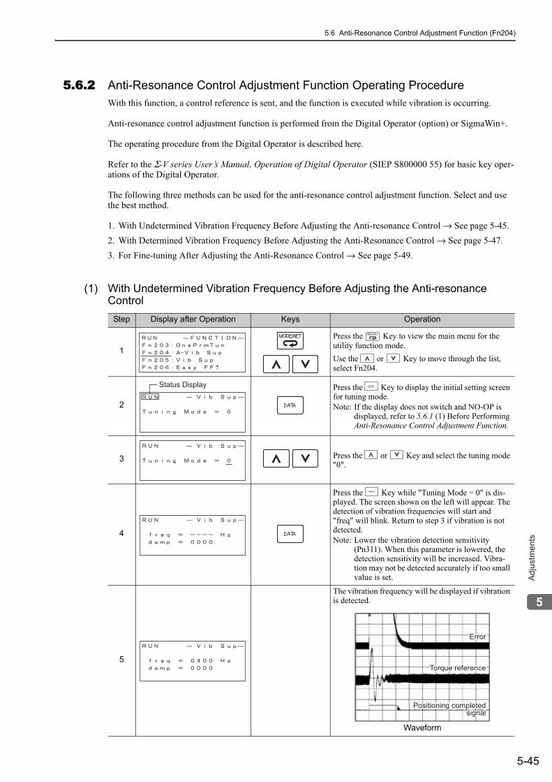
5.6 Anti-Resonance Control Adjustment Function (Fn204)
5-45
5
Ad
justm
en
ts
5.6.2 Anti-Resonance Control Adjustment Function Operating ProcedureWith this function, a control reference is sent, and the function is executed while vibration is occurring.
Anti-resonance control adjustment function is performed from the Digital Operator (option) or SigmaWin+.
The operating procedure from the Digital Operator is described here.
Refer to the Σ-V series User’s Manual, Operation of Digital Operator (SIEP S800000 55) for basic key oper-ations of the Digital Operator.
The following three methods can be used for the anti-resonance control adjustment function. Select and use the best method.
1. With Undetermined Vibration Frequency Before Adjusting the Anti-resonance Control → See page 5-45.2. With Determined Vibration Frequency Before Adjusting the Anti-Resonance Control → See page 5-47.3. For Fine-tuning After Adjusting the Anti-Resonance Control → See page 5-49.
(1) With Undetermined Vibration Frequency Before Adjusting the Anti-resonance Control
Step Display after Operation Keys Operation
1
Press the Key to view the main menu for the utility function mode.Use the or Key to move through the list, select Fn204.
2
Press the Key to display the initial setting screen for tuning mode.Note: If the display does not switch and NO-OP is
displayed, refer to 5.6.1 (1) Before Performing Anti-Resonance Control Adjustment Function.
3 Press the or Key and select the tuning mode "0".
4
Press the Key while "Tuning Mode = 0" is dis-played. The screen shown on the left will appear. The detection of vibration frequencies will start and "freq" will blink. Return to step 3 if vibration is not detected. Note: Lower the vibration detection sensitivity
(Pn311). When this parameter is lowered, the detection sensitivity will be increased. Vibra-tion may not be detected accurately if too small value is set.
5
The vibration frequency will be displayed if vibration is detected.
Waveform
Status Display
ErrorErrorError
Torque reference
Positioning completedPositioning completedsignalsignal
Torque reference
Positioning completedsignal
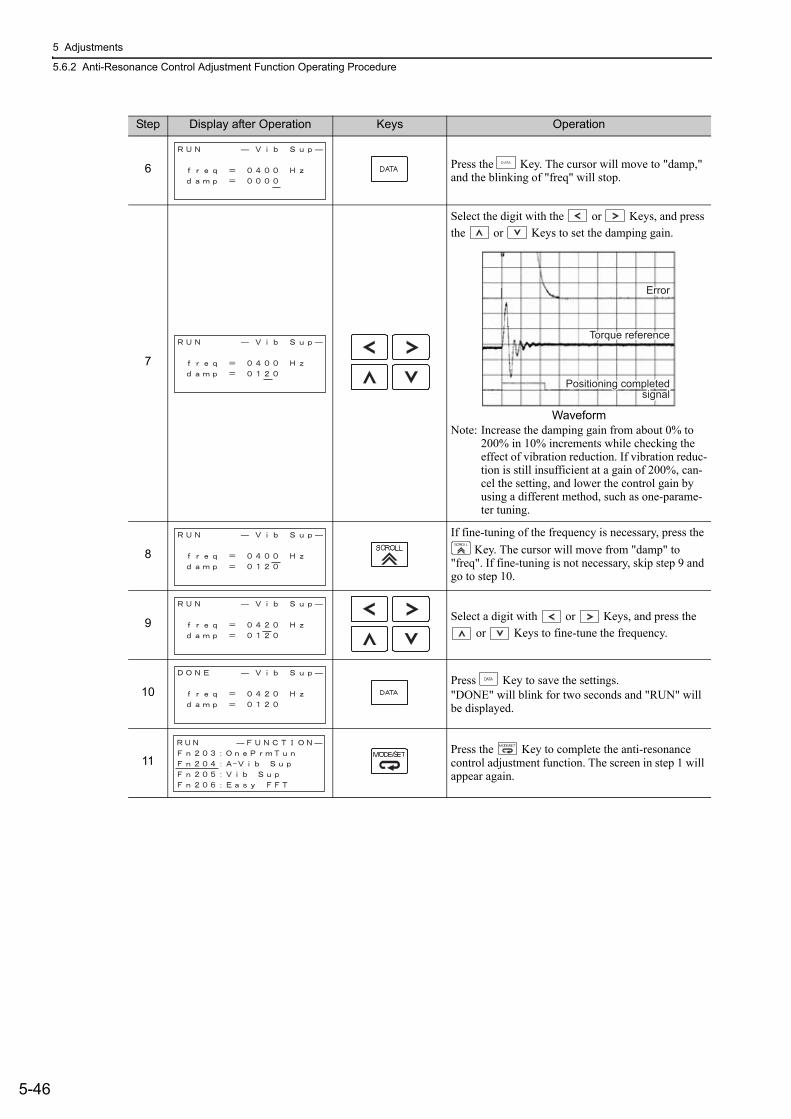
5 Adjustments
5.6.2 Anti-Resonance Control Adjustment Function Operating Procedure
5-46
6 Press the Key. The cursor will move to "damp," and the blinking of "freq" will stop.
7
Select the digit with the or Keys, and press the or Keys to set the damping gain.
WaveformNote: Increase the damping gain from about 0% to
200% in 10% increments while checking the effect of vibration reduction. If vibration reduc-tion is still insufficient at a gain of 200%, can-cel the setting, and lower the control gain by using a different method, such as one-parame-ter tuning.
8
If fine-tuning of the frequency is necessary, press the Key. The cursor will move from "damp" to
"freq". If fine-tuning is not necessary, skip step 9 and go to step 10.
9 Select a digit with or Keys, and press the or Keys to fine-tune the frequency.
10Press Key to save the settings."DONE" will blink for two seconds and "RUN" will be displayed.
11Press the Key to complete the anti-resonance control adjustment function. The screen in step 1 will appear again.
Step Display after Operation Keys Operation
ErrorError
Torque referenceTorque reference
Positioning completedPositioning completedsignalsignal
Error
Torque reference
Positioning completedsignal
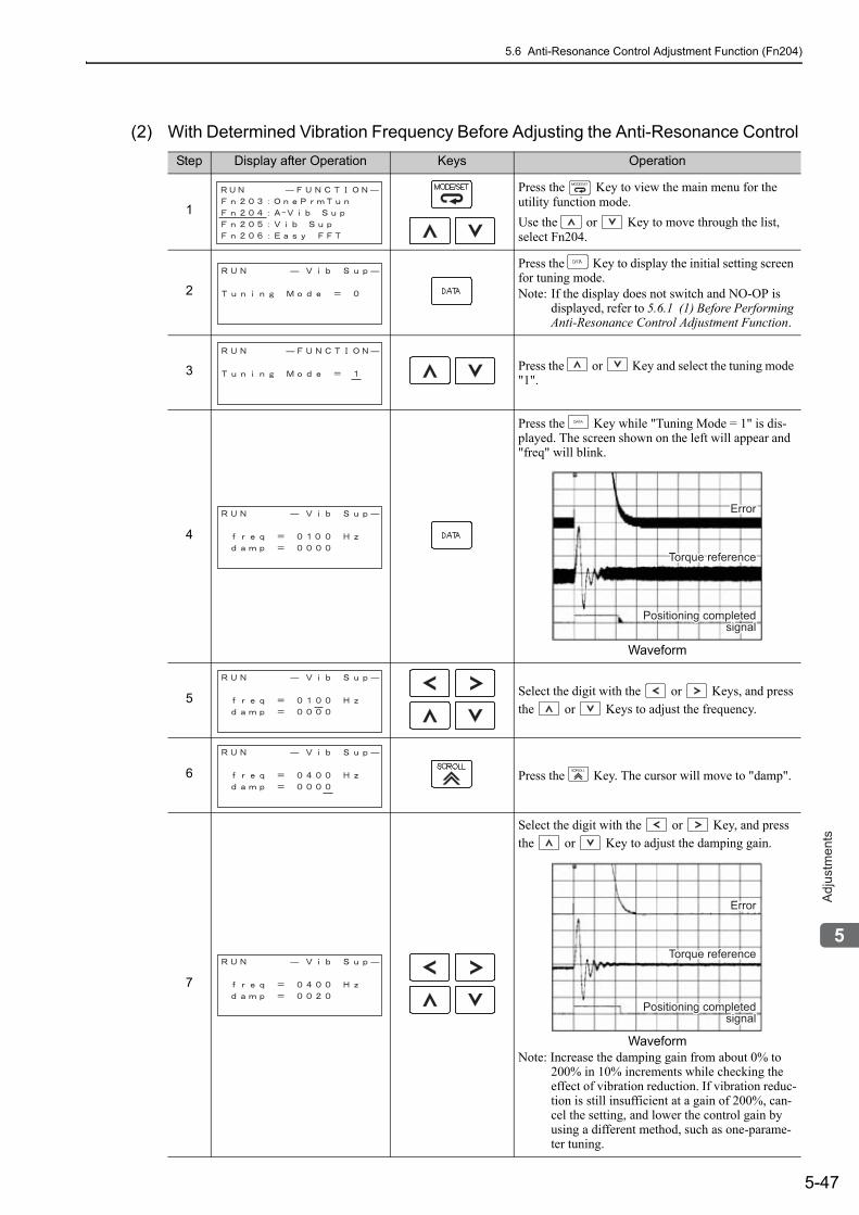
5.6 Anti-Resonance Control Adjustment Function (Fn204)
5-47
5
Ad
justm
en
ts
(2) With Determined Vibration Frequency Before Adjusting the Anti-Resonance Control Step Display after Operation Keys Operation
1
Press the Key to view the main menu for the utility function mode.Use the or Key to move through the list, select Fn204.
2
Press the Key to display the initial setting screen for tuning mode.Note: If the display does not switch and NO-OP is
displayed, refer to 5.6.1 (1) Before Performing Anti-Resonance Control Adjustment Function.
3 Press the or Key and select the tuning mode "1".
4
Press the Key while "Tuning Mode = 1" is dis-played. The screen shown on the left will appear and "freq" will blink.
Waveform
5 Select the digit with the or Keys, and press the or Keys to adjust the frequency.
6 Press the Key. The cursor will move to "damp".
7
Select the digit with the or Key, and press the or Key to adjust the damping gain.
WaveformNote: Increase the damping gain from about 0% to
200% in 10% increments while checking the effect of vibration reduction. If vibration reduc-tion is still insufficient at a gain of 200%, can-cel the setting, and lower the control gain by using a different method, such as one-parame-ter tuning.
ErrorErrorError
Torque reference
Positioning completedPositioning completedsignalsignal
Torque reference
Positioning completedsignal
ErrorError
Torque referenceTorque reference
Positioning completedPositioning completedsignalsignal
Error
Torque reference
Positioning completedsignal
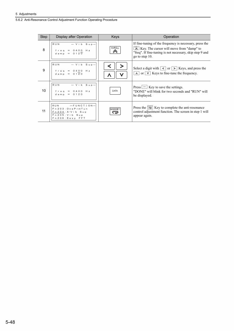
5 Adjustments
5.6.2 Anti-Resonance Control Adjustment Function Operating Procedure
5-48
8
If fine-tuning of the frequency is necessary, press the Key. The cursor will move from "damp" to
"freq". If fine-tuning is not necessary, skip step 9 and go to step 10.
9 Select a digit with or Keys, and press the or Keys to fine-tune the frequency.
10Press Key to save the settings."DONE" will blink for two seconds and "RUN" will be displayed.
11Press the Key to complete the anti-resonance control adjustment function. The screen in step 1 will appear again.
Step Display after Operation Keys Operation
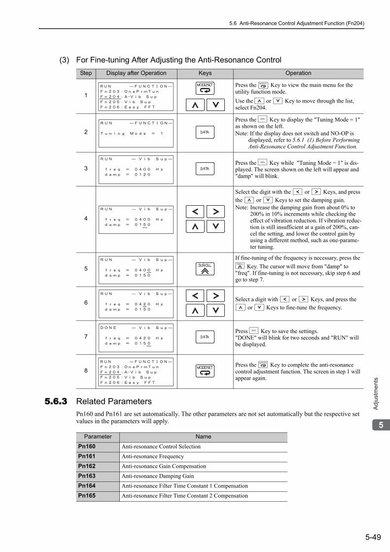
5.6 Anti-Resonance Control Adjustment Function (Fn204)
5-49
5
Ad
justm
en
ts
(3) For Fine-tuning After Adjusting the Anti-Resonance Control
5.6.3 Related ParametersPn160 and Pn161 are set automatically. The other parameters are not set automatically but the respective set values in the parameters will apply.
Step Display after Operation Keys Operation
1
Press the Key to view the main menu for the utility function mode.Use the or Key to move through the list, select Fn204.
2
Press the Key to display the "Tuning Mode = 1" as shown on the left.Note: If the display does not switch and NO-OP is
displayed, refer to 5.6.1 (1) Before Performing Anti-Resonance Control Adjustment Function.
3Press the Key while "Tuning Mode = 1" is dis-played. The screen shown on the left will appear and "damp" will blink.
4
Select the digit with the or Keys, and press the or Keys to set the damping gain.Note: Increase the damping gain from about 0% to
200% in 10% increments while checking the effect of vibration reduction. If vibration reduc-tion is still insufficient at a gain of 200%, can-cel the setting, and lower the control gain by using a different method, such as one-parame-ter tuning.
5
If fine-tuning of the frequency is necessary, press the Key. The cursor will move from "damp" to
"freq". If fine-tuning is not necessary, skip step 6 and go to step 7.
6 Select a digit with or Keys, and press the or Keys to fine-tune the frequency.
7Press Key to save the settings."DONE" will blink for two seconds and "RUN" will be displayed.
8Press the Key to complete the anti-resonance control adjustment function. The screen in step 1 will appear again.
Parameter Name
Pn160 Anti-resonance Control Selection
Pn161 Anti-resonance Frequency
Pn162 Anti-resonance Gain Compensation
Pn163 Anti-resonance Damping Gain
Pn164 Anti-resonance Filter Time Constant 1 Compensation
Pn165 Anti-resonance Filter Time Constant 2 Compensation
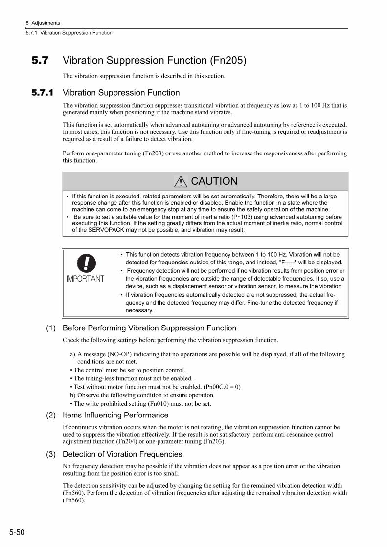
5 Adjustments
5.7.1 Vibration Suppression Function
5-50
5.7 Vibration Suppression Function (Fn205)The vibration suppression function is described in this section.
5.7.1 Vibration Suppression FunctionThe vibration suppression function suppresses transitional vibration at frequency as low as 1 to 100 Hz that is generated mainly when positioning if the machine stand vibrates.
This function is set automatically when advanced autotuning or advanced autotuning by reference is executed. In most cases, this function is not necessary. Use this function only if fine-tuning is required or readjustment is required as a result of a failure to detect vibration.
Perform one-parameter tuning (Fn203) or use another method to increase the responsiveness after performing this function.
(1) Before Performing Vibration Suppression FunctionCheck the following settings before performing the vibration suppression function.
a) A message (NO-OP) indicating that no operations are possible will be displayed, if all of the following conditions are not met.
• The control must be set to position control.• The tuning-less function must not be enabled.• Test without motor function must not be enabled. (Pn00C.0 = 0)b) Observe the following condition to ensure operation.• The write prohibited setting (Fn010) must not be set.
(2) Items Influencing PerformanceIf continuous vibration occurs when the motor is not rotating, the vibration suppression function cannot be used to suppress the vibration effectively. If the result is not satisfactory, perform anti-resonance control adjustment function (Fn204) or one-parameter tuning (Fn203).
(3) Detection of Vibration FrequenciesNo frequency detection may be possible if the vibration does not appear as a position error or the vibration resulting from the position error is too small.
The detection sensitivity can be adjusted by changing the setting for the remained vibration detection width (Pn560). Perform the detection of vibration frequencies after adjusting the remained vibration detection width (Pn560).
CAUTION• If this function is executed, related parameters will be set automatically. Therefore, there will be a large
response change after this function is enabled or disabled. Enable the function in a state where the machine can come to an emergency stop at any time to ensure the safety operation of the machine.
• Be sure to set a suitable value for the moment of inertia ratio (Pn103) using advanced autotuning before executing this function. If the setting greatly differs from the actual moment of inertia ratio, normal control of the SERVOPACK may not be possible, and vibration may result.
• This function detects vibration frequency between 1 to 100 Hz. Vibration will not be detected for frequencies outside of this range, and instead, "F-----" will be displayed.
• Frequency detection will not be performed if no vibration results from position error or the vibration frequencies are outside the range of detectable frequencies. If so, use a device, such as a displacement sensor or vibration sensor, to measure the vibration.
• If vibration frequencies automatically detected are not suppressed, the actual fre-quency and the detected frequency may differ. Fine-tune the detected frequency if necessary.
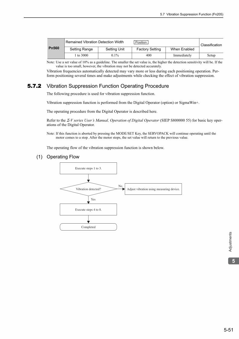
5.7 Vibration Suppression Function (Fn205)
5-51
5
Ad
justm
en
ts
Note: Use a set value of 10% as a guideline. The smaller the set value is, the higher the detection sensitivity will be. If the value is too small, however, the vibration may not be detected accurately.
Vibration frequencies automatically detected may vary more or less during each positioning operation. Per-form positioning several times and make adjustments while checking the effect of vibration suppression.
5.7.2 Vibration Suppression Function Operating ProcedureThe following procedure is used for vibration suppression function.
Vibration suppression function is performed from the Digital Operator (option) or SigmaWin+.
The operating procedure from the Digital Operator is described here.
Refer to the Σ-V series User’s Manual, Operation of Digital Operator (SIEP S800000 55) for basic key oper-ations of the Digital Operator.
Note: If this function is aborted by pressing the MODE/SET Key, the SERVOPACK will continue operating until the motor comes to a stop. After the motor stops, the set value will return to the previous value.
The operating flow of the vibration suppression function is shown below.
(1) Operating Flow
Pn560Remained Vibration Detection Width
ClassificationSetting Range Setting Unit Factory Setting When Enabled
1 to 3000 0.1% 400 Immediately Setup
Position
Vibration detected?
Execute steps 1 to 3.
Completed
Adjust vibration using measuring device.
Execute steps 4 to 8.
Yes
No
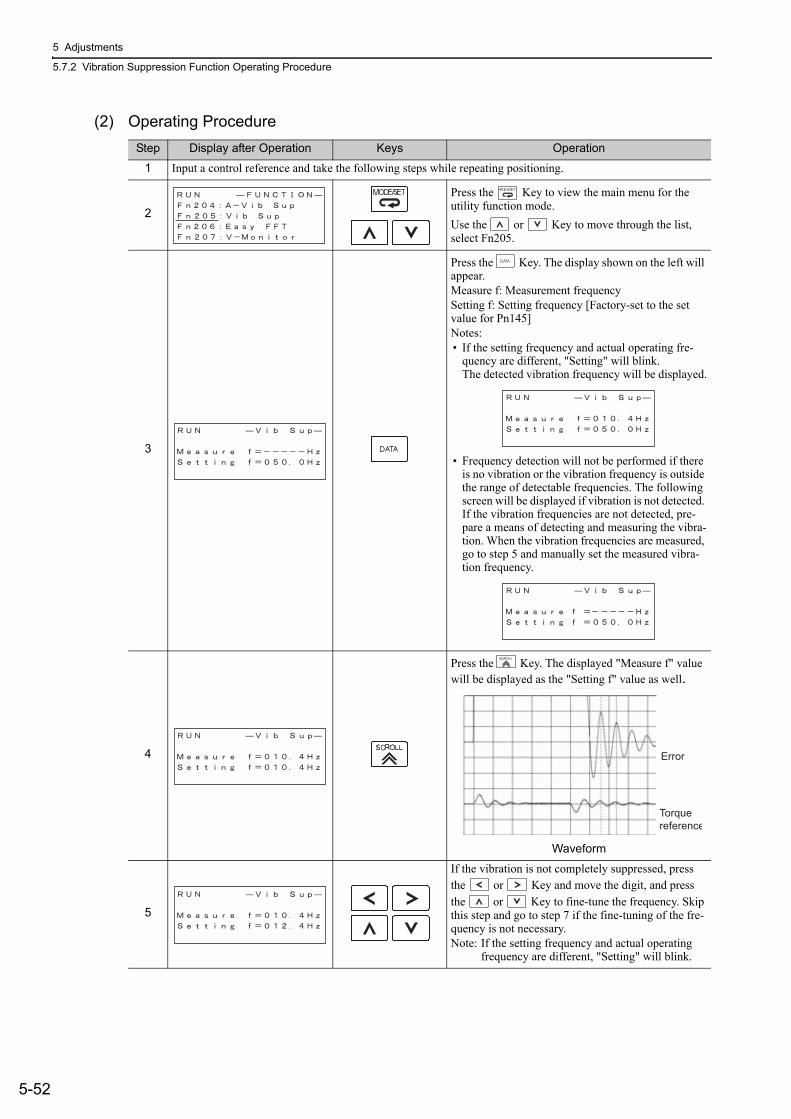
5 Adjustments
5.7.2 Vibration Suppression Function Operating Procedure
5-52
(2) Operating ProcedureStep Display after Operation Keys Operation
1 Input a control reference and take the following steps while repeating positioning.
2
Press the Key to view the main menu for the utility function mode.Use the or Key to move through the list, select Fn205.
3
Press the Key. The display shown on the left will appear.Measure f: Measurement frequencySetting f: Setting frequency [Factory-set to the set value for Pn145]Notes: • If the setting frequency and actual operating fre-
quency are different, "Setting" will blink.The detected vibration frequency will be displayed.
• Frequency detection will not be performed if there is no vibration or the vibration frequency is outside the range of detectable frequencies. The following screen will be displayed if vibration is not detected. If the vibration frequencies are not detected, pre-pare a means of detecting and measuring the vibra-tion. When the vibration frequencies are measured, go to step 5 and manually set the measured vibra-tion frequency.
4
Press the Key. The displayed "Measure f" value will be displayed as the "Setting f" value as well.
Waveform
5
If the vibration is not completely suppressed, press the or Key and move the digit, and press the or Key to fine-tune the frequency. Skip this step and go to step 7 if the fine-tuning of the fre-quency is not necessary.Note: If the setting frequency and actual operating
frequency are different, "Setting" will blink.
Error
Torque reference
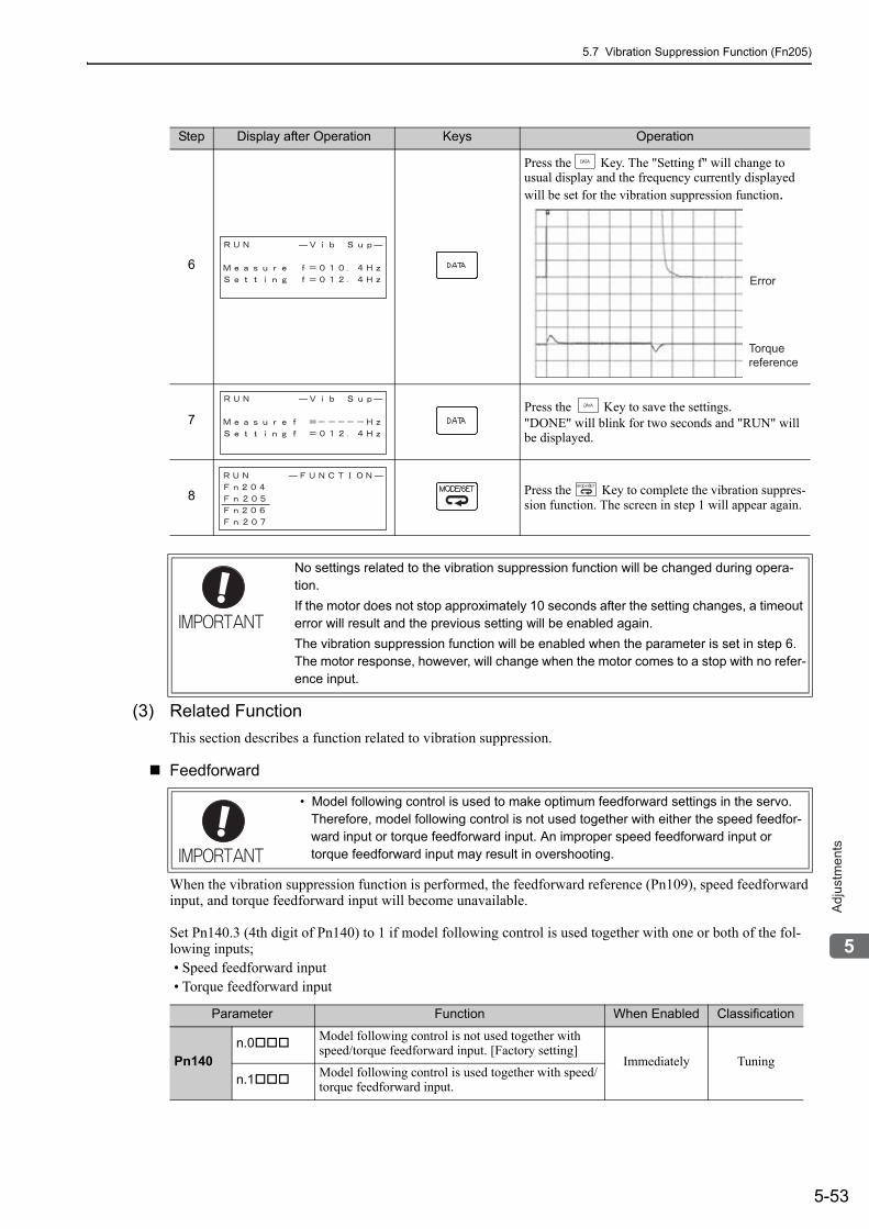
5.7 Vibration Suppression Function (Fn205)
5-53
5
Ad
justm
en
ts
(3) Related Function This section describes a function related to vibration suppression.
Feedforward
When the vibration suppression function is performed, the feedforward reference (Pn109), speed feedforward input, and torque feedforward input will become unavailable.
Set Pn140.3 (4th digit of Pn140) to 1 if model following control is used together with one or both of the fol-lowing inputs;• Speed feedforward input• Torque feedforward input
6
Press the Key. The "Setting f" will change to usual display and the frequency currently displayed will be set for the vibration suppression function.
7Press the Key to save the settings."DONE" will blink for two seconds and "RUN" will be displayed.
8 Press the Key to complete the vibration suppres-sion function. The screen in step 1 will appear again.
Step Display after Operation Keys Operation
Error
Torquereference
No settings related to the vibration suppression function will be changed during opera-tion.If the motor does not stop approximately 10 seconds after the setting changes, a timeout error will result and the previous setting will be enabled again.The vibration suppression function will be enabled when the parameter is set in step 6. The motor response, however, will change when the motor comes to a stop with no refer-ence input.
• Model following control is used to make optimum feedforward settings in the servo. Therefore, model following control is not used together with either the speed feedfor-ward input or torque feedforward input. An improper speed feedforward input or torque feedforward input may result in overshooting.
Parameter Function When Enabled Classification
Pn140n.0 Model following control is not used together with
speed/torque feedforward input. [Factory setting]Immediately Tuning
n.1 Model following control is used together with speed/torque feedforward input.
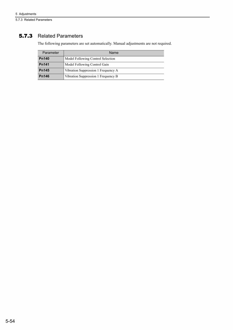
5 Adjustments
5.7.3 Related Parameters
5-54
5.7.3 Related ParametersThe following parameters are set automatically. Manual adjustments are not required.
Parameter Name
Pn140 Model Following Control Selection
Pn141 Model Following Control Gain
Pn145 Vibration Suppression 1 Frequency A
Pn146 Vibration Suppression 1 Frequency B
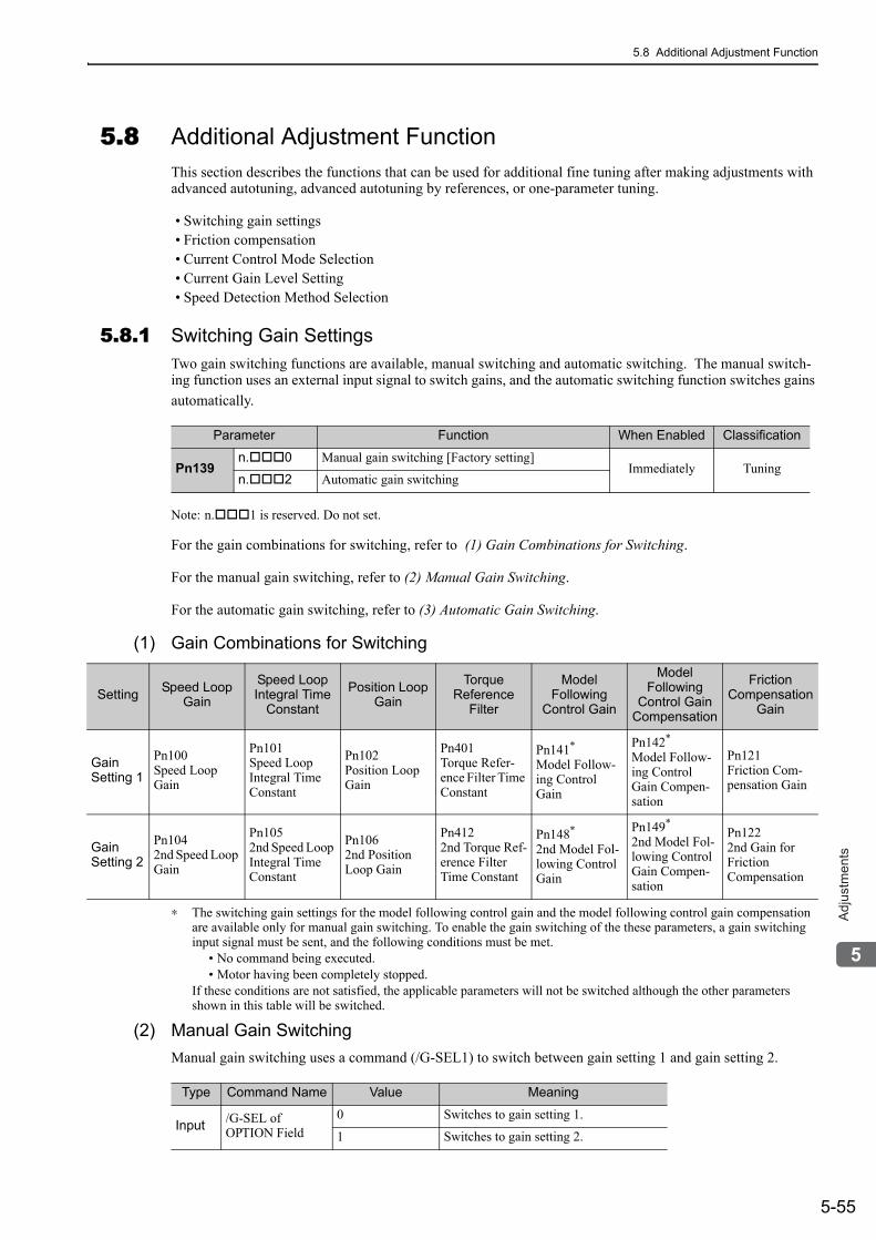
5.8 Additional Adjustment Function
5-55
5
Ad
justm
en
ts
5.8 Additional Adjustment FunctionThis section describes the functions that can be used for additional fine tuning after making adjustments with advanced autotuning, advanced autotuning by references, or one-parameter tuning.
• Switching gain settings• Friction compensation• Current Control Mode Selection• Current Gain Level Setting• Speed Detection Method Selection
5.8.1 Switching Gain SettingsTwo gain switching functions are available, manual switching and automatic switching. The manual switch-ing function uses an external input signal to switch gains, and the automatic switching function switches gains automatically.
Note: n. 1 is reserved. Do not set.
For the gain combinations for switching, refer to (1) Gain Combinations for Switching.
For the manual gain switching, refer to (2) Manual Gain Switching.
For the automatic gain switching, refer to (3) Automatic Gain Switching.
(1) Gain Combinations for Switching
∗ The switching gain settings for the model following control gain and the model following control gain compensation are available only for manual gain switching. To enable the gain switching of the these parameters, a gain switching input signal must be sent, and the following conditions must be met.
• No command being executed.• Motor having been completely stopped.
If these conditions are not satisfied, the applicable parameters will not be switched although the other parameters shown in this table will be switched.
(2) Manual Gain SwitchingManual gain switching uses a command (/G-SEL1) to switch between gain setting 1 and gain setting 2.
Parameter Function When Enabled Classification
Pn139n. 0 Manual gain switching [Factory setting]
Immediately Tuningn. 2 Automatic gain switching
Setting Speed Loop Gain
Speed Loop Integral Time
Constant
Position Loop Gain
Torque Reference
Filter
Model Following
Control Gain
Model Following
Control Gain Compensation
Friction Compensation
Gain
Gain Setting 1
Pn100Speed Loop Gain
Pn101Speed Loop Integral Time Constant
Pn102Position Loop Gain
Pn401Torque Refer-ence Filter Time Constant
Pn141*
Model Follow-ing Control Gain
Pn142*
Model Follow-ing Control Gain Compen-sation
Pn121Friction Com-pensation Gain
Gain Setting 2
Pn1042nd Speed Loop Gain
Pn1052nd Speed Loop Integral Time Constant
Pn1062nd Position Loop Gain
Pn4122nd Torque Ref-erence Filter Time Constant
Pn148*
2nd Model Fol-lowing Control Gain
Pn149*
2nd Model Fol-lowing Control Gain Compen-sation
Pn1222nd Gain for Friction Compensation
Type Command Name Value Meaning
Input /G-SEL of OPTION Field
0 Switches to gain setting 1.
1 Switches to gain setting 2.
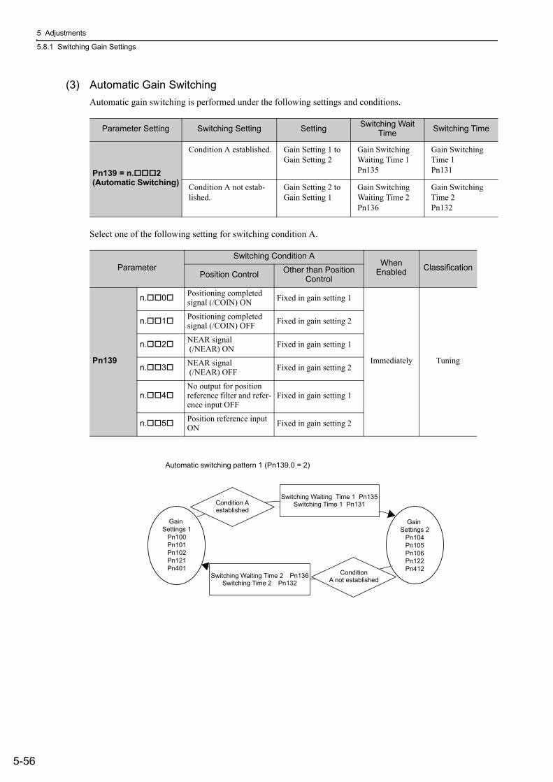
5 Adjustments
5.8.1 Switching Gain Settings
5-56
(3) Automatic Gain SwitchingAutomatic gain switching is performed under the following settings and conditions.
Select one of the following setting for switching condition A.
Parameter Setting Switching Setting Setting Switching Wait Time Switching Time
Pn139 = n. 2(Automatic Switching)
Condition A established. Gain Setting 1 to Gain Setting 2
Gain Switching Waiting Time 1Pn135
Gain Switching Time 1Pn131
Condition A not estab-lished.
Gain Setting 2 to Gain Setting 1
Gain Switching Waiting Time 2Pn136
Gain Switching Time 2Pn132
ParameterSwitching Condition A
When Enabled Classification
Position Control Other than Position Control
Pn139
n. 0 Positioning completed signal (/COIN) ON Fixed in gain setting 1
Immediately Tuning
n. 1 Positioning completed signal (/COIN) OFF Fixed in gain setting 2
n. 2 NEAR signal (/NEAR) ON Fixed in gain setting 1
n. 3 NEAR signal (/NEAR) OFF Fixed in gain setting 2
n. 4No output for position reference filter and refer-ence input OFF
Fixed in gain setting 1
n. 5 Position reference input ON Fixed in gain setting 2
Gain Settings 2
Pn104Pn105Pn106Pn122Pn412
Condition Aestablished
ConditionA not established
Switching Waiting Time 1 Pn135Switching Time 1 Pn131
Switching Waiting Time 2 Pn136Switching Time 2 Pn132
Gain Settings 1
Pn100Pn101Pn102Pn121Pn401
Automatic switching pattern 1 (Pn139.0 = 2)
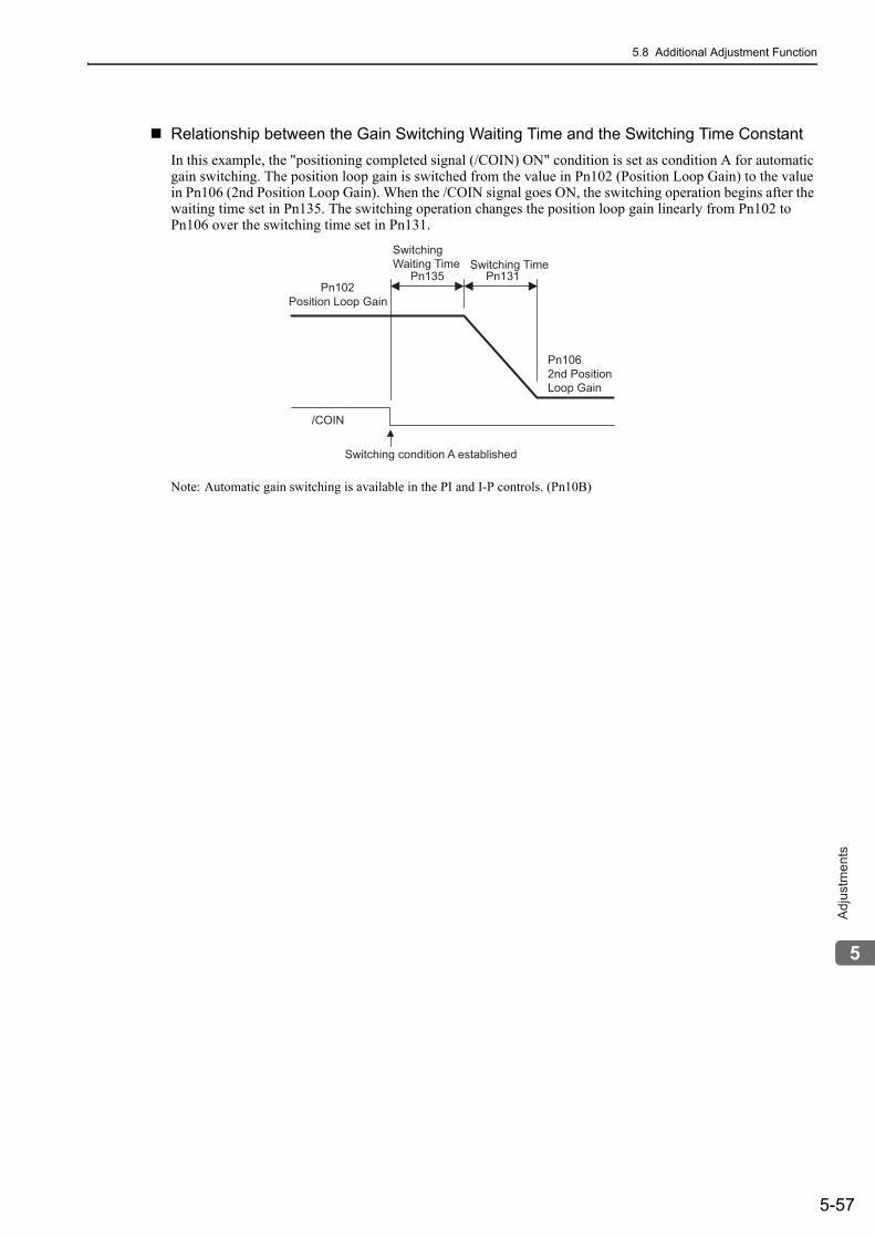
5.8 Additional Adjustment Function
5-57
5
Ad
justm
en
ts
Relationship between the Gain Switching Waiting Time and the Switching Time ConstantIn this example, the "positioning completed signal (/COIN) ON" condition is set as condition A for automatic gain switching. The position loop gain is switched from the value in Pn102 (Position Loop Gain) to the value in Pn106 (2nd Position Loop Gain). When the /COIN signal goes ON, the switching operation begins after the waiting time set in Pn135. The switching operation changes the position loop gain linearly from Pn102 to Pn106 over the switching time set in Pn131.
Note: Automatic gain switching is available in the PI and I-P controls. (Pn10B)
Switching condition A established
Switching Time
Pn131
Switching
Waiting Time
Pn135
Pn102
Position Loop Gain
Pn106
2nd Position
Loop Gain
/COIN
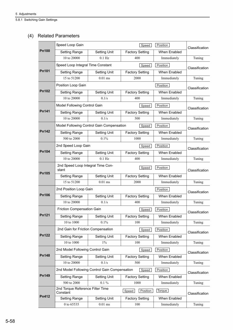
5 Adjustments
5.8.1 Switching Gain Settings
5-58
(4) Related Parameters
Pn100Speed Loop Gain
ClassificationSetting Range Setting Unit Factory Setting When Enabled
10 to 20000 0.1 Hz 400 Immediately Tuning
Pn101Speed Loop Integral Time Constant
ClassificationSetting Range Setting Unit Factory Setting When Enabled
15 to 51200 0.01 ms 2000 Immediately Tuning
Pn102Position Loop Gain
ClassificationSetting Range Setting Unit Factory Setting When Enabled
10 to 20000 0.1/s 400 Immediately Tuning
Pn141Model Following Control Gain
ClassificationSetting Range Setting Unit Factory Setting When Enabled
10 to 20000 0.1/s 500 Immediately Tuning
Pn142Model Following Control Gain Compensation
ClassificationSetting Range Setting Unit Factory Setting When Enabled
500 to 2000 0.1% 1000 Immediately Tuning
Pn1042nd Speed Loop Gain
ClassificationSetting Range Setting Unit Factory Setting When Enabled
10 to 20000 0.1 Hz 400 Immediately Tuning
Pn105
2nd Speed Loop Integral Time Con-stant Classification
Setting Range Setting Unit Factory Setting When Enabled
15 to 51200 0.01 ms 2000 Immediately Tuning
Pn1062nd Position Loop Gain
ClassificationSetting Range Setting Unit Factory Setting When Enabled
10 to 20000 0.1/s 400 Immediately Tuning
Pn121
Friction Compensation GainClassification
Setting Range Setting Unit Factory Setting When Enabled
10 to 1000 0.1% 100 Immediately Tuning
Pn122
2nd Gain for Friction CompensationClassification
Setting Range Setting Unit Factory Setting When Enabled
10 to 1000 1% 100 Immediately Tuning
Pn1482nd Model Following Control Gain
ClassificationSetting Range Setting Unit Factory Setting When Enabled
10 to 20000 0.1/s 500 Immediately Tuning
Pn1492nd Model Following Control Gain Compensation
ClassificationSetting Range Setting Unit Factory Setting When Enabled
500 to 2000 0.1 % 1000 Immediately Tuning
Pn412
2nd Torque Reference Filter Time Constant Classification
Setting Range Setting Unit Factory Setting When Enabled
0 to 65535 0.01 ms 100 Immediately Tuning
Speed Position
Speed Position
Position
Speed Position
Speed Position
Speed Position
Speed Position
Position
Speed Position
Speed Position
Speed Position
Speed Position
Speed Position Torque
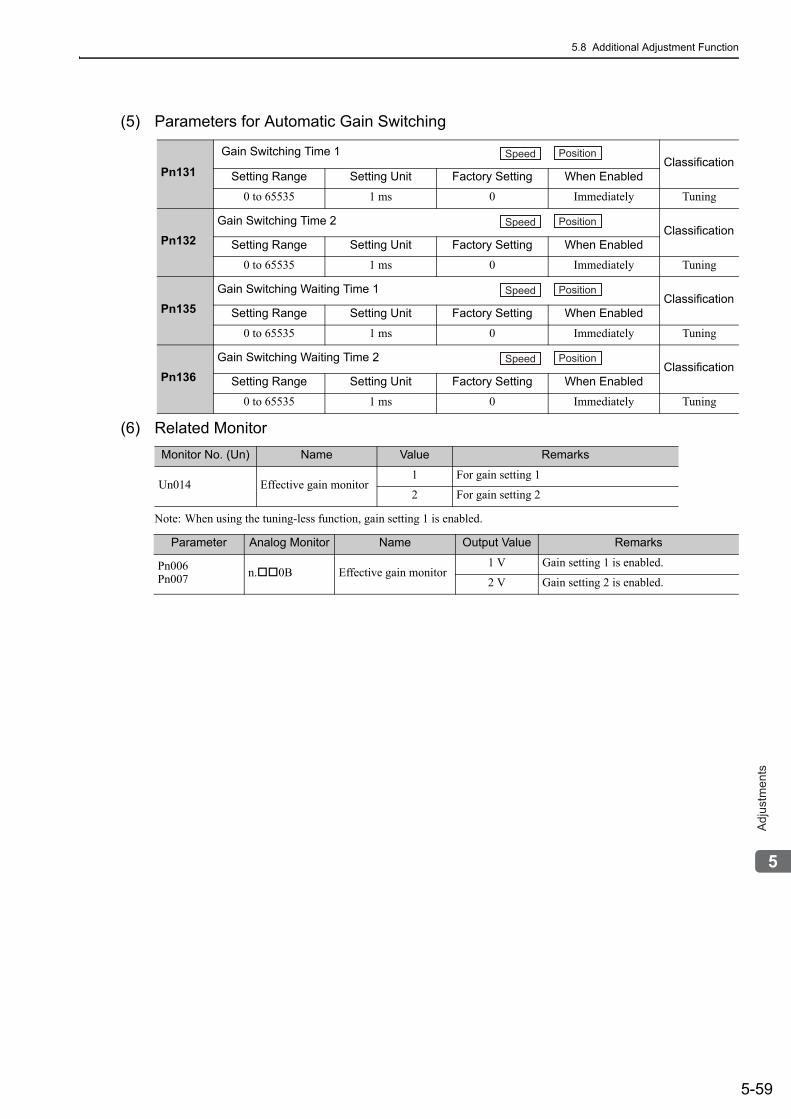
5.8 Additional Adjustment Function
5-59
5
Ad
justm
en
ts
(5) Parameters for Automatic Gain Switching
(6) Related Monitor
Note: When using the tuning-less function, gain setting 1 is enabled.
Pn131
Gain Switching Time 1Classification
Setting Range Setting Unit Factory Setting When Enabled
0 to 65535 1 ms 0 Immediately Tuning
Pn132Gain Switching Time 2
ClassificationSetting Range Setting Unit Factory Setting When Enabled
0 to 65535 1 ms 0 Immediately Tuning
Pn135Gain Switching Waiting Time 1
ClassificationSetting Range Setting Unit Factory Setting When Enabled
0 to 65535 1 ms 0 Immediately Tuning
Pn136Gain Switching Waiting Time 2
ClassificationSetting Range Setting Unit Factory Setting When Enabled
0 to 65535 1 ms 0 Immediately Tuning
Monitor No. (Un) Name Value Remarks
Un014 Effective gain monitor1 For gain setting 1
2 For gain setting 2
Speed Position
Speed Position
Speed Position
Speed Position
Parameter Analog Monitor Name Output Value Remarks
Pn006Pn007 n. 0B Effective gain monitor
1 V Gain setting 1 is enabled.
2 V Gain setting 2 is enabled.
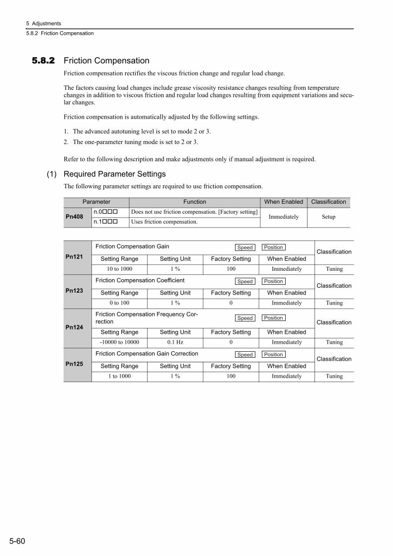
5 Adjustments
5.8.2 Friction Compensation
5-60
5.8.2 Friction CompensationFriction compensation rectifies the viscous friction change and regular load change.
The factors causing load changes include grease viscosity resistance changes resulting from temperature changes in addition to viscous friction and regular load changes resulting from equipment variations and secu-lar changes.
Friction compensation is automatically adjusted by the following settings.
1. The advanced autotuning level is set to mode 2 or 3.2. The one-parameter tuning mode is set to 2 or 3.
Refer to the following description and make adjustments only if manual adjustment is required.
(1) Required Parameter SettingsThe following parameter settings are required to use friction compensation.
Parameter Function When Enabled Classification
Pn408n.0 Does not use friction compensation. [Factory setting]
Immediately Setupn.1 Uses friction compensation.
Pn121
Friction Compensation GainClassification
Setting Range Setting Unit Factory Setting When Enabled
10 to 1000 1 % 100 Immediately Tuning
Pn123
Friction Compensation CoefficientClassification
Setting Range Setting Unit Factory Setting When Enabled
0 to 100 1 % 0 Immediately Tuning
Pn124
Friction Compensation Frequency Cor-rection Classification
Setting Range Setting Unit Factory Setting When Enabled
-10000 to 10000 0.1 Hz 0 Immediately Tuning
Pn125
Friction Compensation Gain CorrectionClassification
Setting Range Setting Unit Factory Setting When Enabled
1 to 1000 1 % 100 Immediately Tuning
Speed Position
Speed Position
Speed Position
Speed Position
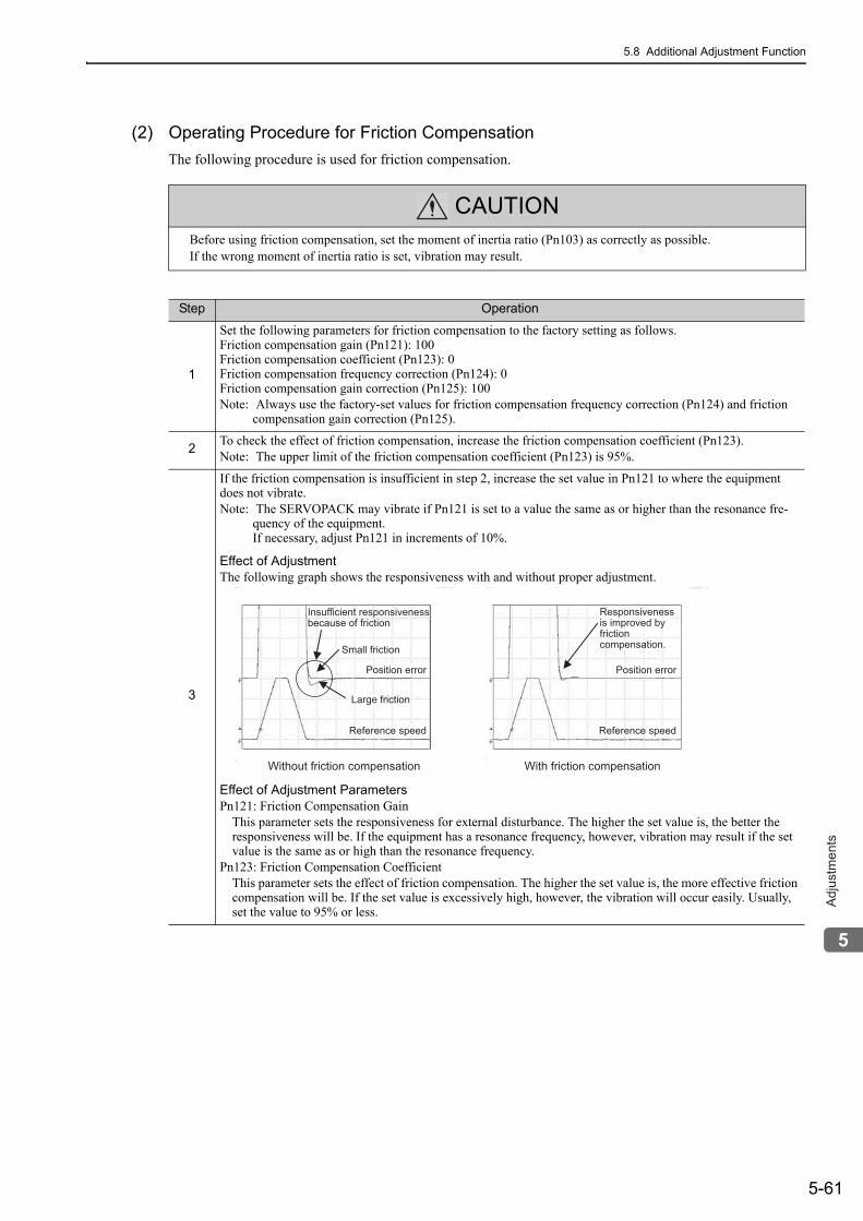
5.8 Additional Adjustment Function
5-61
5
Ad
justm
en
ts
(2) Operating Procedure for Friction CompensationThe following procedure is used for friction compensation.
CAUTIONBefore using friction compensation, set the moment of inertia ratio (Pn103) as correctly as possible.If the wrong moment of inertia ratio is set, vibration may result.
Step Operation
1
Set the following parameters for friction compensation to the factory setting as follows.Friction compensation gain (Pn121): 100Friction compensation coefficient (Pn123): 0Friction compensation frequency correction (Pn124): 0Friction compensation gain correction (Pn125): 100Note: Always use the factory-set values for friction compensation frequency correction (Pn124) and friction
compensation gain correction (Pn125).
2 To check the effect of friction compensation, increase the friction compensation coefficient (Pn123).Note: The upper limit of the friction compensation coefficient (Pn123) is 95%.
3
If the friction compensation is insufficient in step 2, increase the set value in Pn121 to where the equipment does not vibrate.Note: The SERVOPACK may vibrate if Pn121 is set to a value the same as or higher than the resonance fre-
quency of the equipment.If necessary, adjust Pn121 in increments of 10%.
Effect of AdjustmentThe following graph shows the responsiveness with and without proper adjustment.
Effect of Adjustment ParametersPn121: Friction Compensation Gain
This parameter sets the responsiveness for external disturbance. The higher the set value is, the better the responsiveness will be. If the equipment has a resonance frequency, however, vibration may result if the set value is the same as or high than the resonance frequency.
Pn123: Friction Compensation CoefficientThis parameter sets the effect of friction compensation. The higher the set value is, the more effective friction compensation will be. If the set value is excessively high, however, the vibration will occur easily. Usually, set the value to 95% or less.
Position error
Reference speed
Position error
Reference speed
Small friction
Responsiveness is improved by friction compensation.
Large friction
Without friction compensation With friction compensation
Insufficient responsiveness because of friction
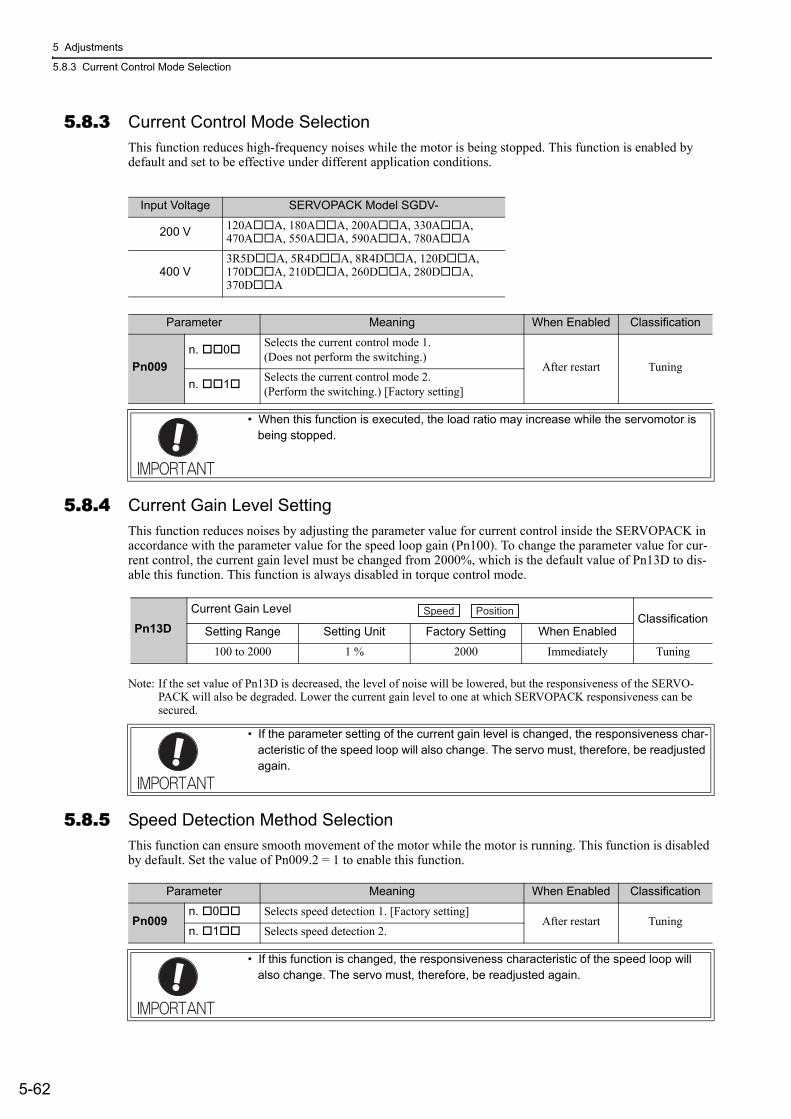
5 Adjustments
5.8.3 Current Control Mode Selection
5-62
5.8.3 Current Control Mode SelectionThis function reduces high-frequency noises while the motor is being stopped. This function is enabled by default and set to be effective under different application conditions.
5.8.4 Current Gain Level SettingThis function reduces noises by adjusting the parameter value for current control inside the SERVOPACK in accordance with the parameter value for the speed loop gain (Pn100). To change the parameter value for cur-rent control, the current gain level must be changed from 2000%, which is the default value of Pn13D to dis-able this function. This function is always disabled in torque control mode.
Note: If the set value of Pn13D is decreased, the level of noise will be lowered, but the responsiveness of the SERVO-PACK will also be degraded. Lower the current gain level to one at which SERVOPACK responsiveness can be secured.
5.8.5 Speed Detection Method SelectionThis function can ensure smooth movement of the motor while the motor is running. This function is disabled by default. Set the value of Pn009.2 = 1 to enable this function.
Input Voltage SERVOPACK Model SGDV-
200 V 120A A, 180A A, 200A A, 330A A, 470A A, 550A A, 590A A, 780A A
400 V3R5D A, 5R4D A, 8R4D A, 120D A, 170D A, 210D A, 260D A, 280D A, 370D A
Parameter Meaning When Enabled Classification
Pn009n. 0 Selects the current control mode 1.
(Does not perform the switching.)After restart Tuning
n. 1 Selects the current control mode 2.(Perform the switching.) [Factory setting]
• When this function is executed, the load ratio may increase while the servomotor is being stopped.
Pn13DCurrent Gain Level
ClassificationSetting Range Setting Unit Factory Setting When Enabled
100 to 2000 1 % 2000 Immediately Tuning
• If the parameter setting of the current gain level is changed, the responsiveness char-acteristic of the speed loop will also change. The servo must, therefore, be readjusted again.
Speed Position
Parameter Meaning When Enabled Classification
Pn009n. 0 Selects speed detection 1. [Factory setting]
After restart Tuningn. 1 Selects speed detection 2.
• If this function is changed, the responsiveness characteristic of the speed loop will also change. The servo must, therefore, be readjusted again.
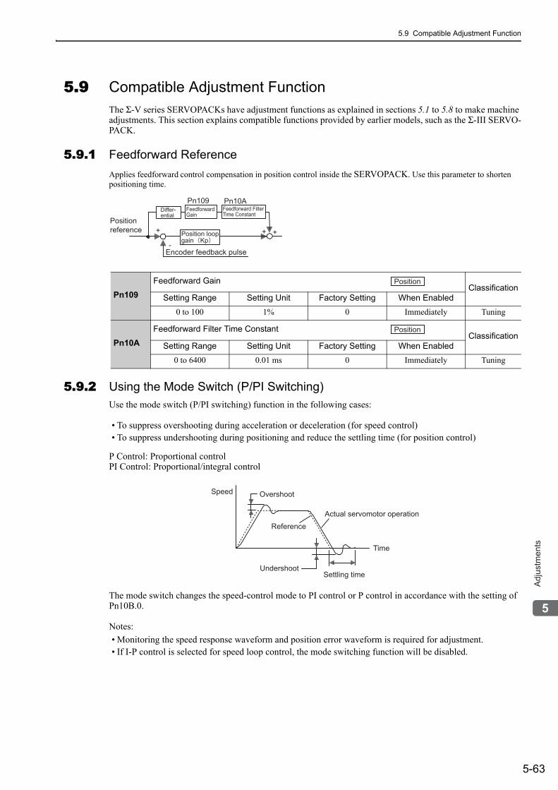
5.9 Compatible Adjustment Function
5-63
5
Ad
justm
en
ts
5.9 Compatible Adjustment FunctionThe Σ-V series SERVOPACKs have adjustment functions as explained in sections 5.1 to 5.8 to make machine adjustments. This section explains compatible functions provided by earlier models, such as the Σ-III SERVO-PACK.
5.9.1 Feedforward ReferenceApplies feedforward control compensation in position control inside the SERVOPACK. Use this parameter to shorten positioning time.
5.9.2 Using the Mode Switch (P/PI Switching)Use the mode switch (P/PI switching) function in the following cases:
• To suppress overshooting during acceleration or deceleration (for speed control)• To suppress undershooting during positioning and reduce the settling time (for position control)
P Control: Proportional controlPI Control: Proportional/integral control
The mode switch changes the speed-control mode to PI control or P control in accordance with the setting of Pn10B.0.
Notes: • Monitoring the speed response waveform and position error waveform is required for adjustment. • If I-P control is selected for speed loop control, the mode switching function will be disabled.
Pn109Feedforward Gain
ClassificationSetting Range Setting Unit Factory Setting When Enabled
0 to 100 1% 0 Immediately Tuning
Pn10AFeedforward Filter Time Constant
ClassificationSetting Range Setting Unit Factory Setting When Enabled
0 to 6400 0.01 ms 0 Immediately Tuning
Positionreference
Encoder feedback pulse
+ + +
-Position loop gain Kp
Pn109 Pn10ADiffer-ential
FeedforwardGain
Feedforward Filter Time Constant
Position
Position
Actual servomotor operation
OvershootSpeed
Reference
Settling timeUndershoot
Time
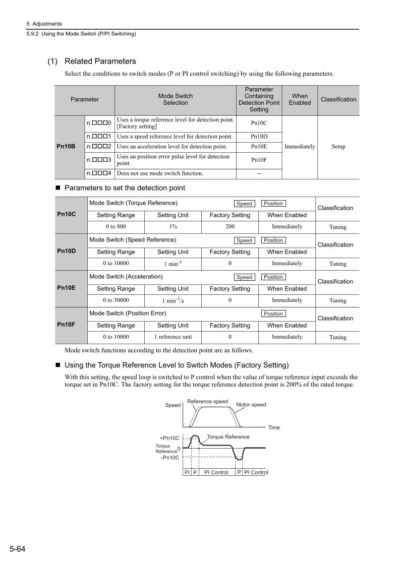
5 Adjustments
5.9.2 Using the Mode Switch (P/PI Switching)
5-64
(1) Related ParametersSelect the conditions to switch modes (P or PI control switching) by using the following parameters.
Parameters to set the detection point
Mode switch functions according to the detection point are as follows.
Using the Torque Reference Level to Switch Modes (Factory Setting)With this setting, the speed loop is switched to P control when the value of torque reference input exceeds the torque set in Pn10C. The factory setting for the torque reference detection point is 200% of the rated torque.
Parameter Mode SwitchSelection
Parameter Containing
Detection PointSetting
When Enabled Classification
Pn10B
n. 0 Uses a torque reference level for detection point.[Factory setting] Pn10C
Immediately Setup
n. 1 Uses a speed reference level for detection point. Pn10D
n. 2 Uses an acceleration level for detection point. Pn10E
n. 3 Uses an position error pulse level for detection point. Pn10F
n. 4 Does not use mode switch function. −
Pn10C
Mode Switch (Torque Reference)Classification
Setting Range Setting Unit Factory Setting When Enabled
0 to 800 1% 200 Immediately Tuning
Pn10D
Mode Switch (Speed Reference)Classification
Setting Range Setting Unit Factory Setting When Enabled
0 to 10000 1 min-1 0 Immediately Tuning
Pn10E
Mode Switch (Acceleration)Classification
Setting Range Setting Unit Factory Setting When Enabled
0 to 30000 1 min-1/s 0 Immediately Tuning
Pn10F
Mode Switch (Position Error)Classification
Setting Range Setting Unit Factory Setting When Enabled
0 to 10000 1 reference unit 0 Immediately Tuning
Speed Position
Speed Position
Speed Position
Position
Motor speedReference speedSpeed
+Pn10CTorque Reference
-Pn10C
Torque Reference
PI Control PI Control
0
PI PP
Time
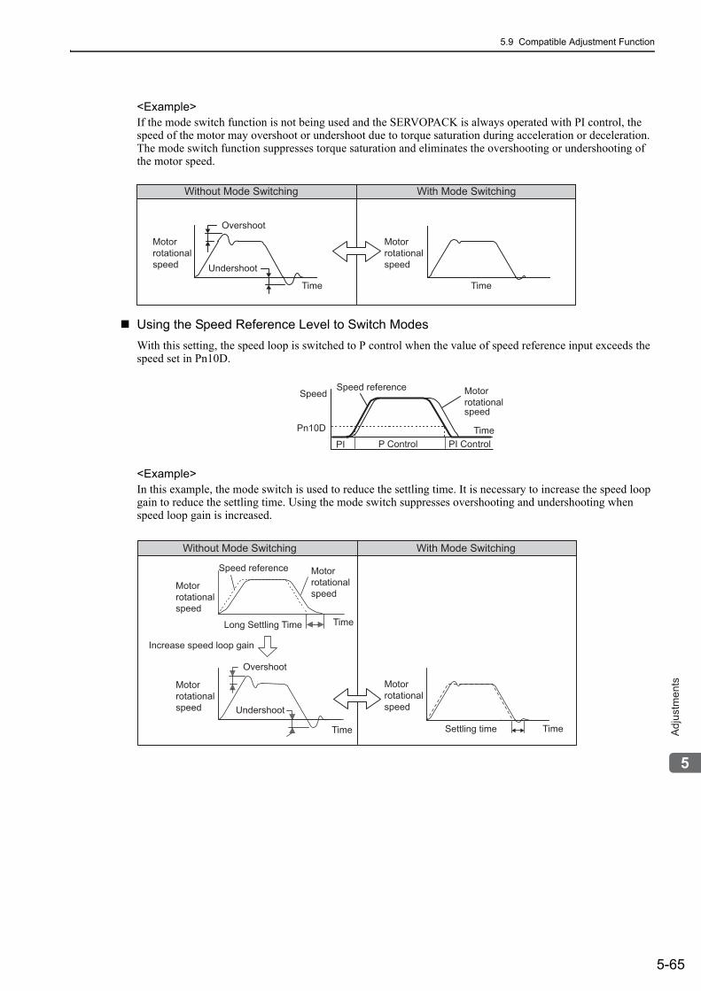
5.9 Compatible Adjustment Function
5-65
5
Ad
justm
en
ts
<Example>If the mode switch function is not being used and the SERVOPACK is always operated with PI control, the speed of the motor may overshoot or undershoot due to torque saturation during acceleration or deceleration. The mode switch function suppresses torque saturation and eliminates the overshooting or undershooting of the motor speed.
Using the Speed Reference Level to Switch ModesWith this setting, the speed loop is switched to P control when the value of speed reference input exceeds the speed set in Pn10D.
<Example>In this example, the mode switch is used to reduce the settling time. It is necessary to increase the speed loop gain to reduce the settling time. Using the mode switch suppresses overshooting and undershooting when speed loop gain is increased.
Without Mode Switching With Mode Switching
Overshoot
Undershoot
Motor rotationalspeed
Time
Motor rotationalspeed
Time
Speed referenceSpeed Motor
rotational speed
TimeP Control PI Control
Pn10D
PI
Without Mode Switching With Mode Switching
Motor rotational speed
Speed reference
Long Settling Time
Increase speed loop gain
Settling time
Motor rotational speed
Overshoot
Undershoot
Motor rotational speed
Time
Motorrotational speed
Time
Time
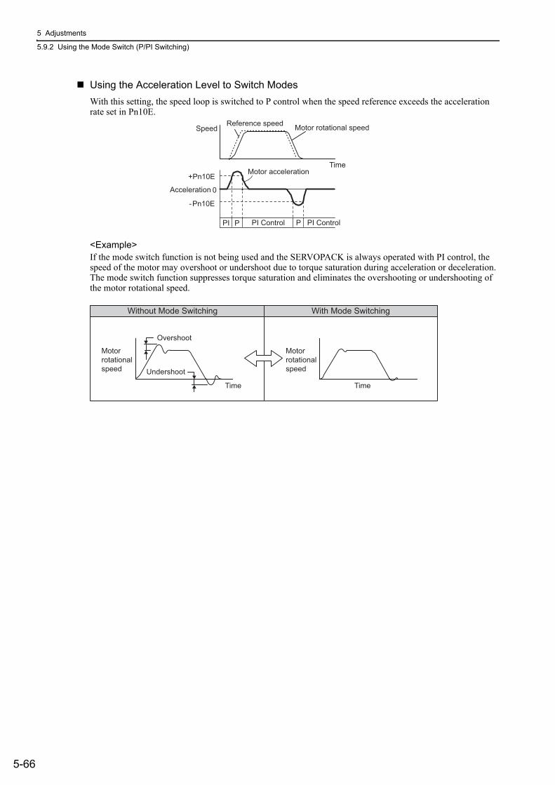
5 Adjustments
5.9.2 Using the Mode Switch (P/PI Switching)
5-66
Using the Acceleration Level to Switch ModesWith this setting, the speed loop is switched to P control when the speed reference exceeds the acceleration rate set in Pn10E.
<Example>If the mode switch function is not being used and the SERVOPACK is always operated with PI control, the speed of the motor may overshoot or undershoot due to torque saturation during acceleration or deceleration. The mode switch function suppresses torque saturation and eliminates the overshooting or undershooting of the motor rotational speed.
Motor rotational speedReference speedSpeed
Motor acceleration+Pn10E
Acceleration
-Pn10E
PI Control PI Control
0
PI PP
Time
Without Mode Switching With Mode Switching
Overshoot
Undershoot
Motorrotational speed
Time
Motorrotational speed
Time
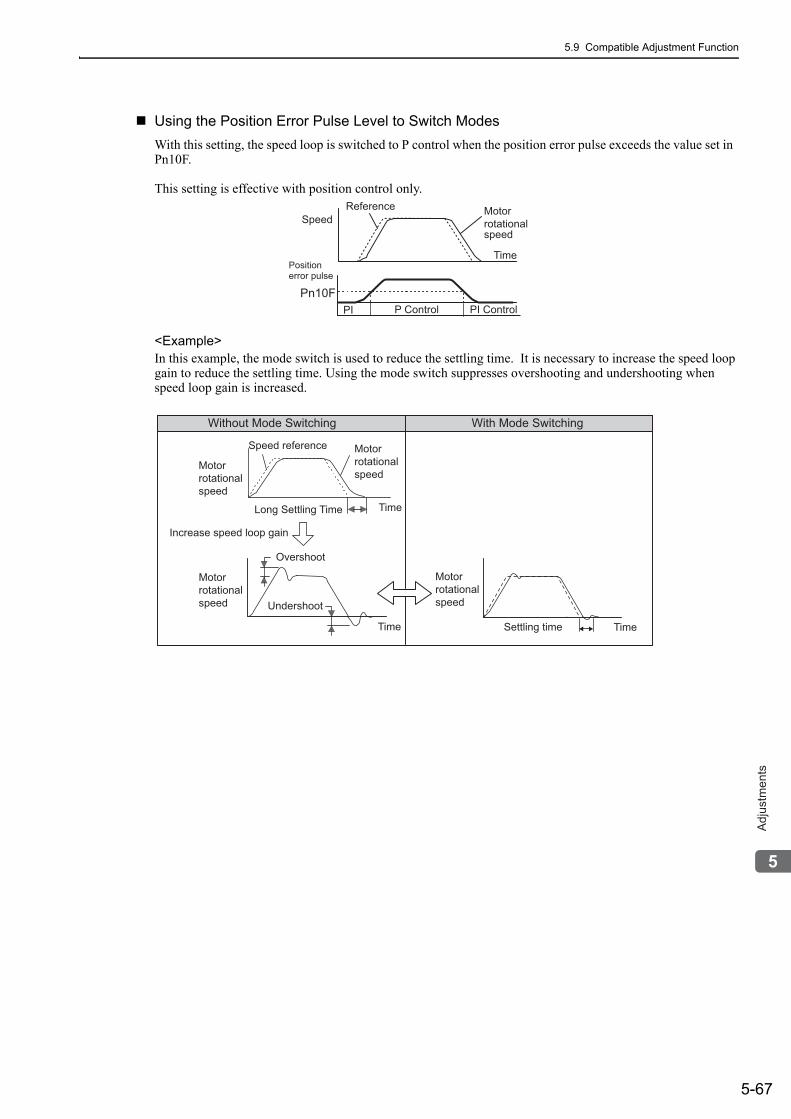
5.9 Compatible Adjustment Function
5-67
5
Ad
justm
en
ts
Using the Position Error Pulse Level to Switch ModesWith this setting, the speed loop is switched to P control when the position error pulse exceeds the value set in Pn10F.
This setting is effective with position control only.
<Example>In this example, the mode switch is used to reduce the settling time. It is necessary to increase the speed loop gain to reduce the settling time. Using the mode switch suppresses overshooting and undershooting when speed loop gain is increased.
Position error pulse
ReferenceSpeed
Motor rotational speed
Time
P Control PI ControlPn10F
PI
Without Mode Switching With Mode Switching
Motor rotational speed
Speed reference
Long Settling Time
Increase speed loop gain
Settling time
Motor rotational speed
Overshoot
Undershoot
Motorrotational speed
Time
Motorrotational speed
Time
Time
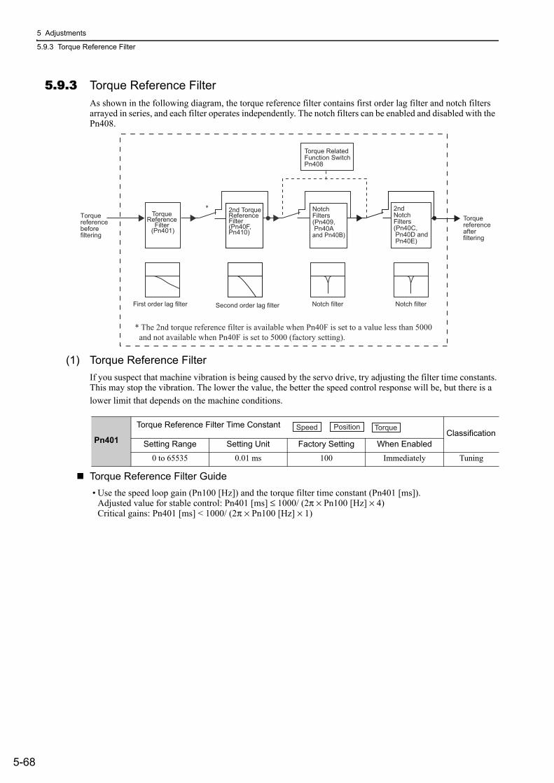
5 Adjustments
5.9.3 Torque Reference Filter
5-68
5.9.3 Torque Reference FilterAs shown in the following diagram, the torque reference filter contains first order lag filter and notch filters arrayed in series, and each filter operates independently. The notch filters can be enabled and disabled with the Pn408.
(1) Torque Reference FilterIf you suspect that machine vibration is being caused by the servo drive, try adjusting the filter time constants. This may stop the vibration. The lower the value, the better the speed control response will be, but there is a lower limit that depends on the machine conditions.
Torque Reference Filter Guide• Use the speed loop gain (Pn100 [Hz]) and the torque filter time constant (Pn401 [ms]).
Adjusted value for stable control: Pn401 [ms] ≤ 1000/ (2π × Pn100 [Hz] × 4)Critical gains: Pn401 [ms] < 1000/ (2π × Pn100 [Hz] × 1)
Torque referencebefore filtering
Torque Reference
Filter (Pn401)
Torque RelatedFunction SwitchPn408
Notch filter Notch filterFirst order lag filter
Torque reference after filtering
Second order lag filter
2nd Torque Reference Filter (Pn40F, Pn410)
2nd Notch Filters (Pn40C, Pn40D and Pn40E)
Notch Filters (Pn409, Pn40Aand Pn40B)
* The 2nd torque reference filter is available when Pn40F is set to a value less than 5000 and not available when Pn40F is set to 5000 (factory setting).
*
Pn401
Torque Reference Filter Time Constant ClassificationSetting Range Setting Unit Factory Setting When Enabled
0 to 65535 0.01 ms 100 Immediately Tuning
Speed Position Torque
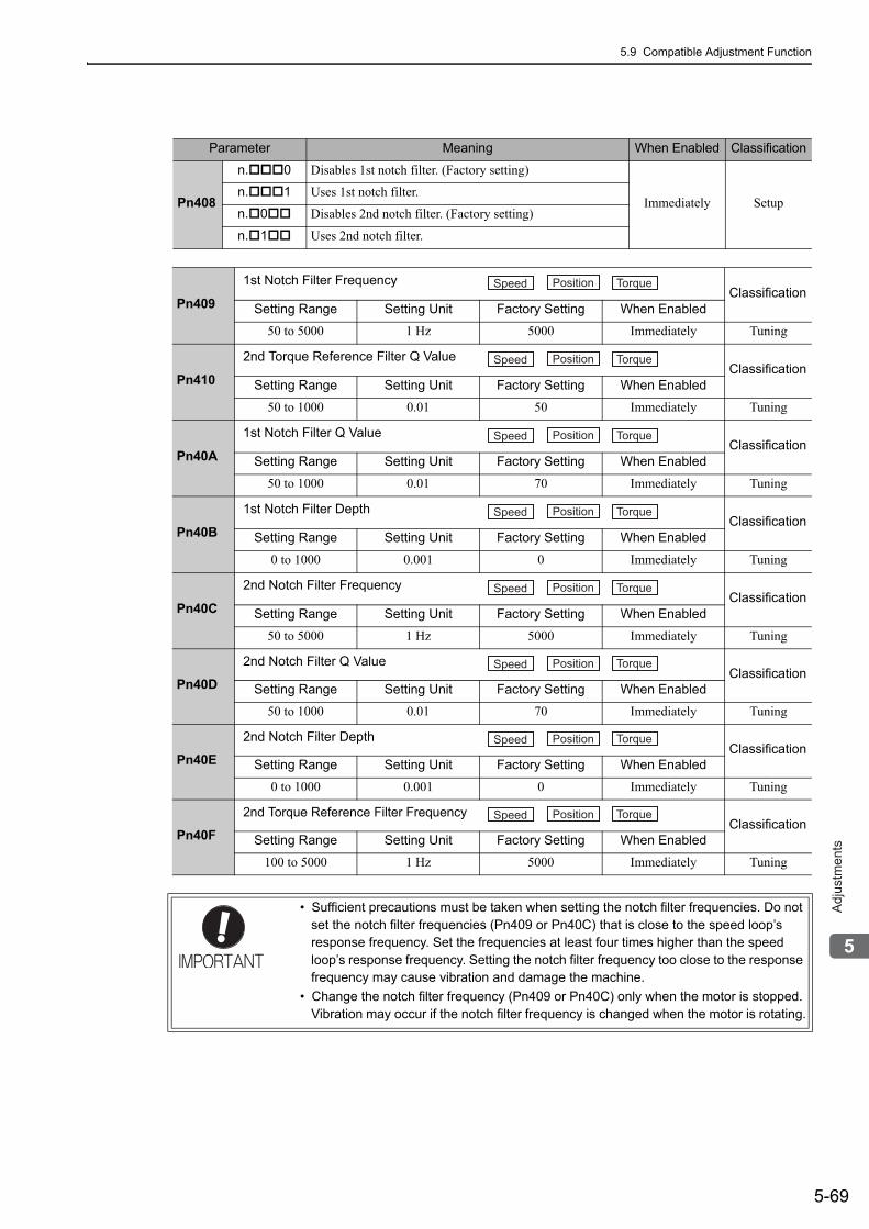
5.9 Compatible Adjustment Function
5-69
5
Ad
justm
en
ts
Parameter Meaning When Enabled Classification
Pn408
n. 0 Disables 1st notch filter. (Factory setting)
Immediately Setupn. 1 Uses 1st notch filter.
n. 0 Disables 2nd notch filter. (Factory setting)
n. 1 Uses 2nd notch filter.
Pn409
1st Notch Filter Frequency ClassificationSetting Range Setting Unit Factory Setting When Enabled
50 to 5000 1 Hz 5000 Immediately Tuning
Pn410
2nd Torque Reference Filter Q Value ClassificationSetting Range Setting Unit Factory Setting When Enabled
50 to 1000 0.01 50 Immediately Tuning
Pn40A
1st Notch Filter Q Value ClassificationSetting Range Setting Unit Factory Setting When Enabled
50 to 1000 0.01 70 Immediately Tuning
Pn40B
1st Notch Filter Depth ClassificationSetting Range Setting Unit Factory Setting When Enabled
0 to 1000 0.001 0 Immediately Tuning
Pn40C
2nd Notch Filter Frequency ClassificationSetting Range Setting Unit Factory Setting When Enabled
50 to 5000 1 Hz 5000 Immediately Tuning
Pn40D
2nd Notch Filter Q Value ClassificationSetting Range Setting Unit Factory Setting When Enabled
50 to 1000 0.01 70 Immediately Tuning
Pn40E
2nd Notch Filter Depth ClassificationSetting Range Setting Unit Factory Setting When Enabled
0 to 1000 0.001 0 Immediately Tuning
Pn40F
2nd Torque Reference Filter Frequency ClassificationSetting Range Setting Unit Factory Setting When Enabled
100 to 5000 1 Hz 5000 Immediately Tuning
• Sufficient precautions must be taken when setting the notch filter frequencies. Do not set the notch filter frequencies (Pn409 or Pn40C) that is close to the speed loop’s response frequency. Set the frequencies at least four times higher than the speed loop’s response frequency. Setting the notch filter frequency too close to the response frequency may cause vibration and damage the machine.
• Change the notch filter frequency (Pn409 or Pn40C) only when the motor is stopped. Vibration may occur if the notch filter frequency is changed when the motor is rotating.
Speed Position Torque
Speed Position Torque
Speed Position Torque
Speed Position Torque
Speed Position Torque
Speed Position Torque
Speed Position Torque
Speed Position Torque

5 Adjustments
5.9.4 Position Integral Time Constant
5-70
5.9.4 Position Integral Time ConstantThis function adds an integral control operation to the position loop. It is effective for electronic cam or elec-tronic shaft applications.
Pn11F
Position Integral Time ConstantClassification
Setting Range Setting Unit Factory Setting When Enabled
0 to 50000 0.1 ms 0 Immediately Tuning
Position
6-1
6
Utility
Fu
nctio
ns (
Fn���
)
6Utility Functions (Fn )
6.1 List of Utility Functions . . . . . . . . . . . . . . . . . . . . . . . . . . . . . . . . . . . . . . .6-2
6.2 Alarm History Display (Fn000) . . . . . . . . . . . . . . . . . . . . . . . . . . . . . . . . .6-3
6.3 JOG Operation (Fn002) . . . . . . . . . . . . . . . . . . . . . . . . . . . . . . . . . . . . . .6-4
6.4 Origin Search (Fn003) . . . . . . . . . . . . . . . . . . . . . . . . . . . . . . . . . . . . . . .6-6
6.5 Program JOG Operation (Fn004) . . . . . . . . . . . . . . . . . . . . . . . . . . . . . . .6-8
6.6 Initializing Parameter Settings (Fn005) . . . . . . . . . . . . . . . . . . . . . . . . . . 6-13
6.7 Clearing Alarm History (Fn006) . . . . . . . . . . . . . . . . . . . . . . . . . . . . . . . 6-14
6.8 Offset adjustment of Analog Monitor Output (Fn00C) . . . . . . . . . . . . . . . 6-15
6.9 Gain Adjustment of Analog Monitor Output (Fn00D) . . . . . . . . . . . . . . . 6-17
6.10 Automatic Offset-Signal Adjustment of the Motor Current Detection (Fn00E) . . . . . . . . . . . . . . . . . . . . . . . . . . . . . . . . . . . . . . . . . 6-19
6.11 Manual Offset-Signal Adjustment of the Motor Current Detection (Fn00F) . . . . . . . . . . . . . . . . . . . . . . . . . . . . . . . . . . . . . . . . . 6-20
6.12 Write Prohibited Setting (Fn010) . . . . . . . . . . . . . . . . . . . . . . . . . . . . . . 6-21
6.13 Servomotor Model Display (Fn011) . . . . . . . . . . . . . . . . . . . . . . . . . . .6-23
6.14 Software Version Display (Fn012) . . . . . . . . . . . . . . . . . . . . . . . . . . . .6-24
6.15 Resetting Configuration Error of Option Module (Fn014) . . . . . . . . . . .6-25
6.16 Vibration Detection Level Initialization (Fn01B) . . . . . . . . . . . . . . . . . . 6-26
6.17 Display of SERVOPACK and Servomotor ID (Fn01E) . . . . . . . . . . . . . 6-28
6.18 Display of Servomotor ID in Feedback Option Module (Fn01F) . . . . . .6-29
6.19 Origin Setting (Fn020) . . . . . . . . . . . . . . . . . . . . . . . . . . . . . . . . . . . . . .6-30
6.20 Software Reset (Fn030) . . . . . . . . . . . . . . . . . . . . . . . . . . . . . . . . . . . . 6-31
6.21 EasyFFT (Fn206) . . . . . . . . . . . . . . . . . . . . . . . . . . . . . . . . . . . . . . . . . 6-32
6.22 Online Vibration Monitor (Fn207) . . . . . . . . . . . . . . . . . . . . . . . . . . . . . 6-36
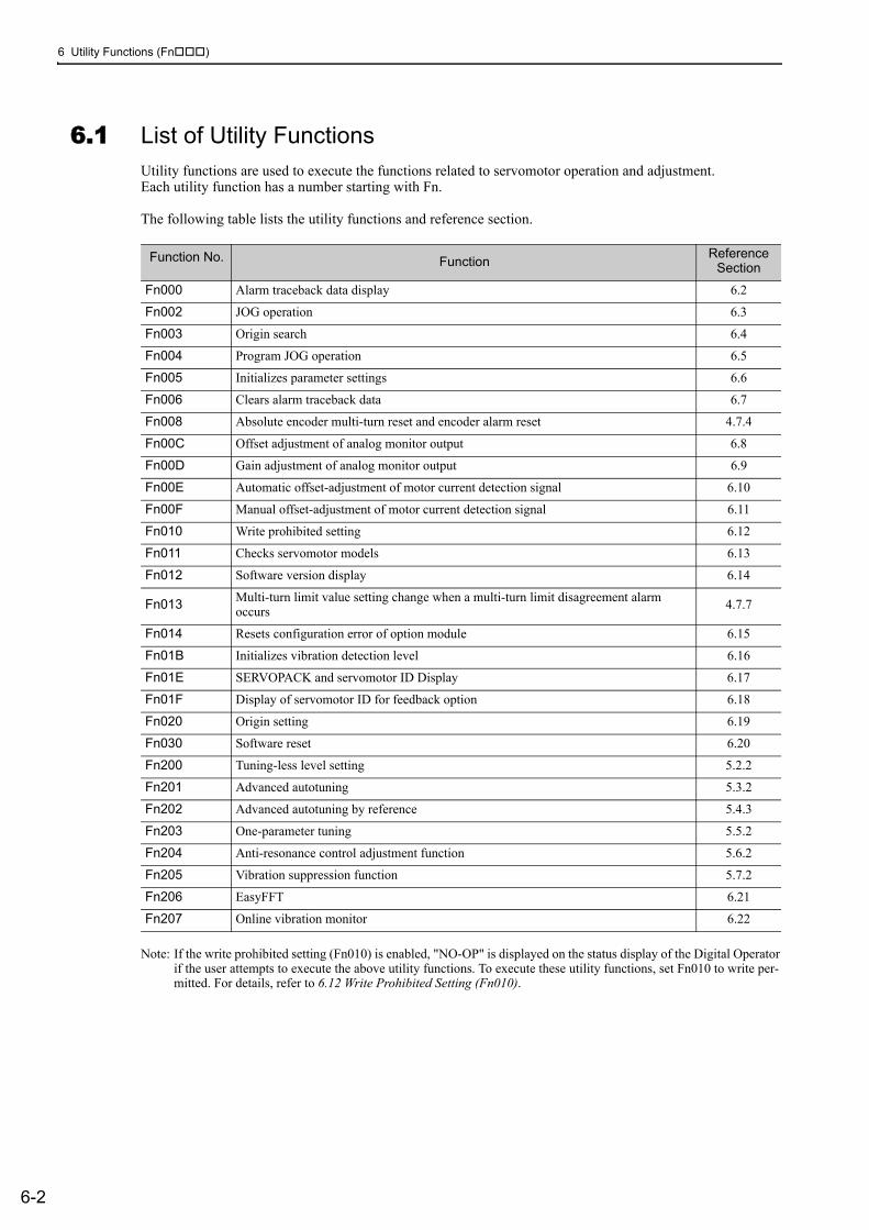
6 Utility Functions (Fn )
6-2
6.1 List of Utility FunctionsUtility functions are used to execute the functions related to servomotor operation and adjustment. Each utility function has a number starting with Fn.
The following table lists the utility functions and reference section.
Note: If the write prohibited setting (Fn010) is enabled, "NO-OP" is displayed on the status display of the Digital Operator if the user attempts to execute the above utility functions. To execute these utility functions, set Fn010 to write per-mitted. For details, refer to 6.12 Write Prohibited Setting (Fn010).
Function No. Function Reference Section
Fn000 Alarm traceback data display 6.2
Fn002 JOG operation 6.3
Fn003 Origin search 6.4
Fn004 Program JOG operation 6.5
Fn005 Initializes parameter settings 6.6
Fn006 Clears alarm traceback data 6.7
Fn008 Absolute encoder multi-turn reset and encoder alarm reset 4.7.4
Fn00C Offset adjustment of analog monitor output 6.8
Fn00D Gain adjustment of analog monitor output 6.9
Fn00E Automatic offset-adjustment of motor current detection signal 6.10
Fn00F Manual offset-adjustment of motor current detection signal 6.11
Fn010 Write prohibited setting 6.12
Fn011 Checks servomotor models 6.13
Fn012 Software version display 6.14
Fn013 Multi-turn limit value setting change when a multi-turn limit disagreement alarm occurs 4.7.7
Fn014 Resets configuration error of option module 6.15
Fn01B Initializes vibration detection level 6.16
Fn01E SERVOPACK and servomotor ID Display 6.17
Fn01F Display of servomotor ID for feedback option 6.18
Fn020 Origin setting 6.19
Fn030 Software reset 6.20
Fn200 Tuning-less level setting 5.2.2
Fn201 Advanced autotuning 5.3.2
Fn202 Advanced autotuning by reference 5.4.3
Fn203 One-parameter tuning 5.5.2
Fn204 Anti-resonance control adjustment function 5.6.2
Fn205 Vibration suppression function 5.7.2
Fn206 EasyFFT 6.21
Fn207 Online vibration monitor 6.22
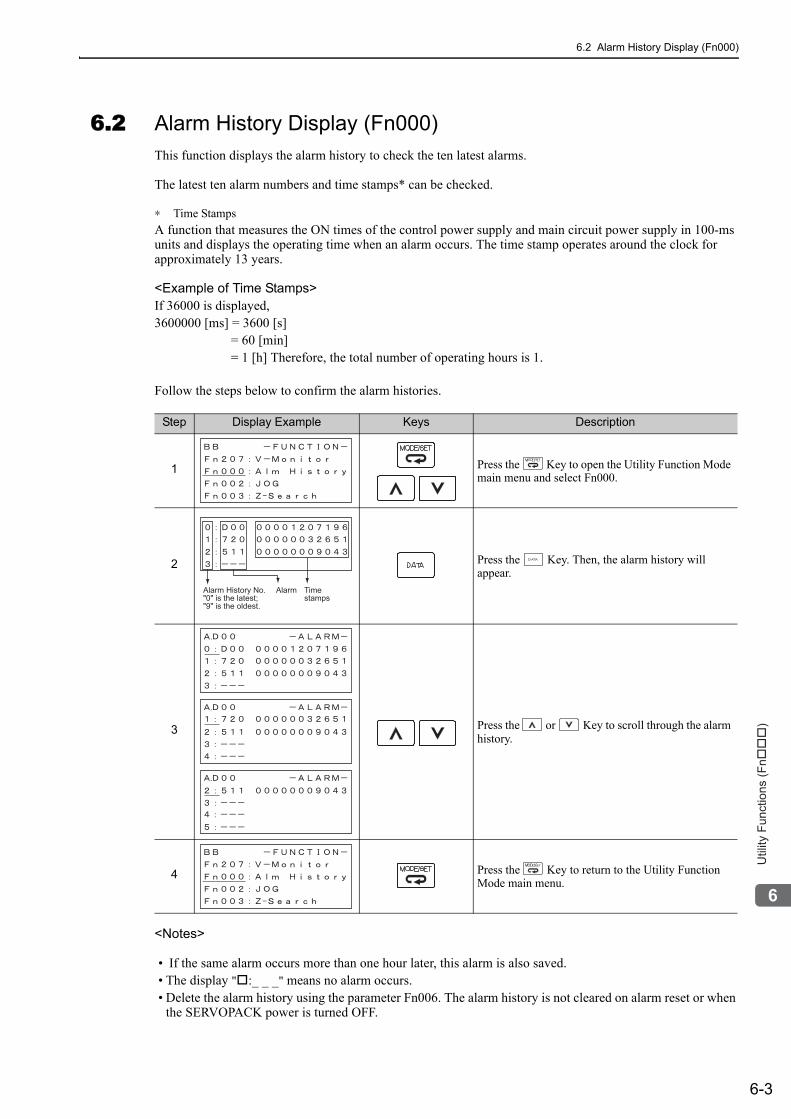
6.2 Alarm History Display (Fn000)
6-3
6
Utility
Fu
nctio
ns (
Fn���
)
6.2 Alarm History Display (Fn000)This function displays the alarm history to check the ten latest alarms.
The latest ten alarm numbers and time stamps* can be checked.
∗ Time StampsA function that measures the ON times of the control power supply and main circuit power supply in 100-ms units and displays the operating time when an alarm occurs. The time stamp operates around the clock for approximately 13 years.
<Example of Time Stamps>If 36000 is displayed,3600000 [ms] = 3600 [s] = 60 [min] = 1 [h] Therefore, the total number of operating hours is 1.
Follow the steps below to confirm the alarm histories.
<Notes>
• If the same alarm occurs more than one hour later, this alarm is also saved. • The display " :_ _ _" means no alarm occurs.• Delete the alarm history using the parameter Fn006. The alarm history is not cleared on alarm reset or when
the SERVOPACK power is turned OFF.
Step Display Example Keys Description
1 Press the Key to open the Utility Function Mode main menu and select Fn000.
2 Press the Key. Then, the alarm history will appear.
3 Press the or Key to scroll through the alarm history.
4 Press the Key to return to the Utility Function Mode main menu.
Alarm History No.
"0" is the latest;
"9" is the oldest.
Alarm Time
stamps
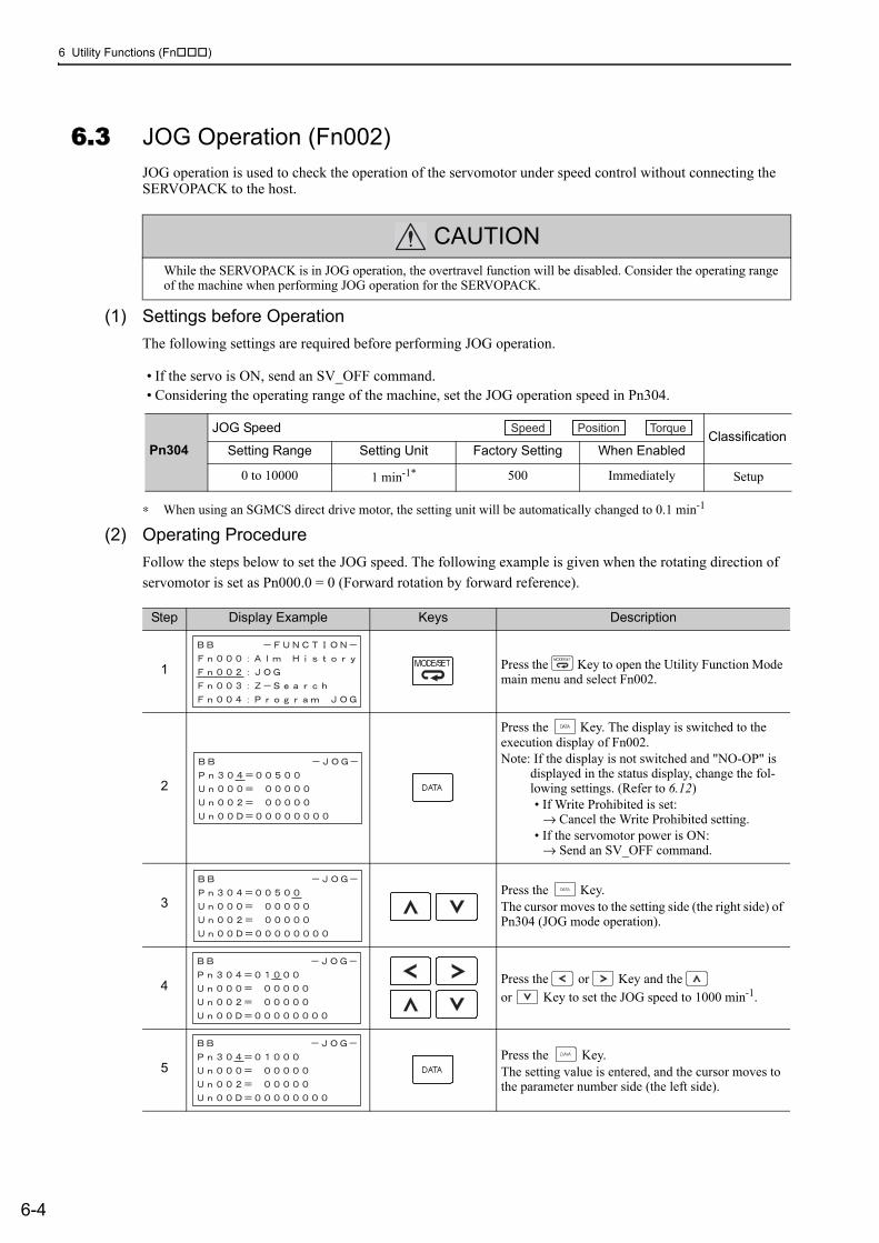
6 Utility Functions (Fn )
6-4
6.3 JOG Operation (Fn002)JOG operation is used to check the operation of the servomotor under speed control without connecting the SERVOPACK to the host.
(1) Settings before OperationThe following settings are required before performing JOG operation.
• If the servo is ON, send an SV_OFF command.• Considering the operating range of the machine, set the JOG operation speed in Pn304.
∗ When using an SGMCS direct drive motor, the setting unit will be automatically changed to 0.1 min-1
(2) Operating ProcedureFollow the steps below to set the JOG speed. The following example is given when the rotating direction of servomotor is set as Pn000.0 = 0 (Forward rotation by forward reference).
CAUTIONWhile the SERVOPACK is in JOG operation, the overtravel function will be disabled. Consider the operating range of the machine when performing JOG operation for the SERVOPACK.
Pn304JOG Speed
ClassificationSetting Range Setting Unit Factory Setting When Enabled
0 to 10000 1 min-1* 500 Immediately Setup
Speed Position Torque
Step Display Example Keys Description
1 Press the Key to open the Utility Function Mode main menu and select Fn002.
2
Press the Key. The display is switched to the execution display of Fn002.Note: If the display is not switched and "NO-OP" is
displayed in the status display, change the fol-lowing settings. (Refer to 6.12)• If Write Prohibited is set:
→ Cancel the Write Prohibited setting.• If the servomotor power is ON:
→ Send an SV_OFF command.
3Press the Key.The cursor moves to the setting side (the right side) of Pn304 (JOG mode operation).
4 Press the or Key and the or Key to set the JOG speed to 1000 min-1.
5Press the Key.The setting value is entered, and the cursor moves to the parameter number side (the left side).
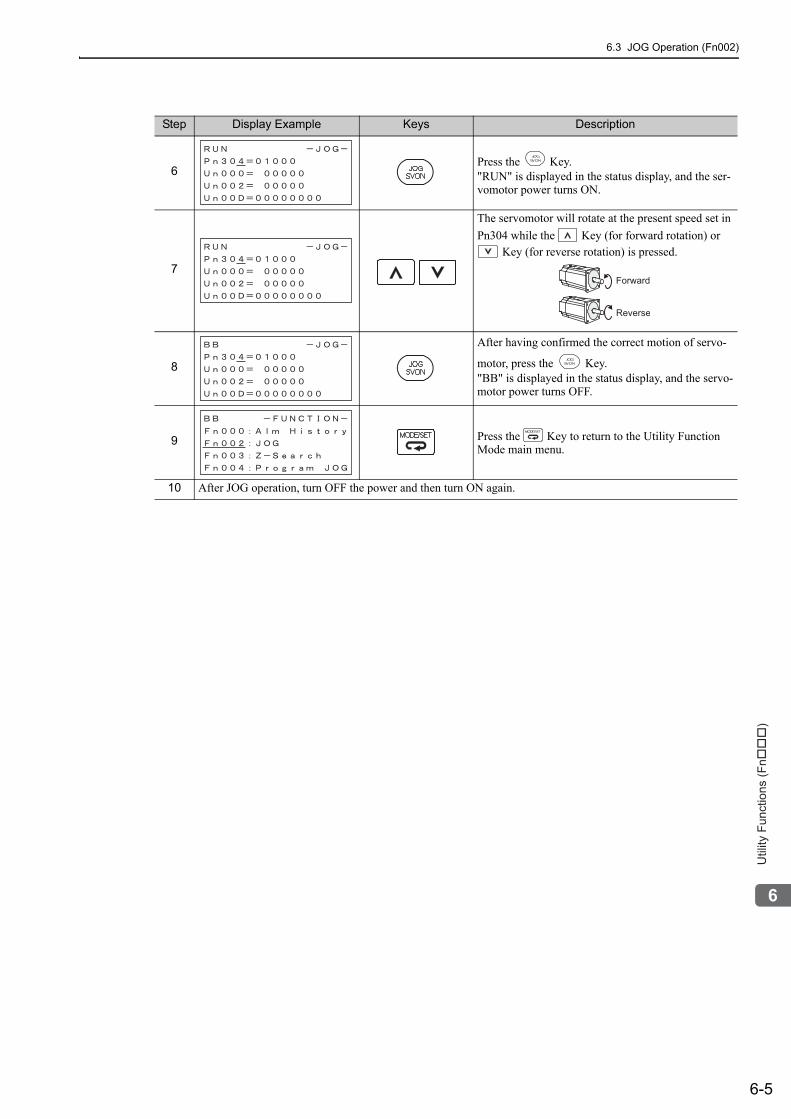
6.3 JOG Operation (Fn002)
6-5
6
Utility
Fu
nctio
ns (
Fn���
)
6Press the Key."RUN" is displayed in the status display, and the ser-vomotor power turns ON.
7
The servomotor will rotate at the present speed set in Pn304 while the Key (for forward rotation) or
Key (for reverse rotation) is pressed.
8
After having confirmed the correct motion of servo-
motor, press the Key."BB" is displayed in the status display, and the servo-motor power turns OFF.
9 Press the Key to return to the Utility Function Mode main menu.
10 After JOG operation, turn OFF the power and then turn ON again.
Step Display Example Keys Description
Forward
Reverse
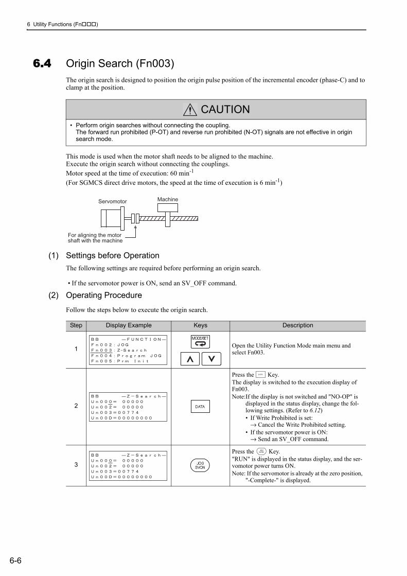
6 Utility Functions (Fn )
6-6
6.4 Origin Search (Fn003)The origin search is designed to position the origin pulse position of the incremental encoder (phase-C) and to clamp at the position.
This mode is used when the motor shaft needs to be aligned to the machine.Execute the origin search without connecting the couplings. Motor speed at the time of execution: 60 min-1
(For SGMCS direct drive motors, the speed at the time of execution is 6 min-1)
(1) Settings before OperationThe following settings are required before performing an origin search.
• If the servomotor power is ON, send an SV_OFF command.
(2) Operating Procedure
Follow the steps below to execute the origin search.
CAUTION• Perform origin searches without connecting the coupling.
The forward run prohibited (P-OT) and reverse run prohibited (N-OT) signals are not effective in origin search mode.
For aligning the motor
shaft with the machine
Servomotor Machine
Step Display Example Keys Description
1 Open the Utility Function Mode main menu and select Fn003.
2
Press the Key.The display is switched to the execution display of Fn003.Note:If the display is not switched and "NO-OP" is
displayed in the status display, change the fol-lowing settings. (Refer to 6.12)• If Write Prohibited is set:
→ Cancel the Write Prohibited setting.• If the servomotor power is ON:
→ Send an SV_OFF command.
3
Press the Key."RUN" is displayed in the status display, and the ser-vomotor power turns ON.Note: If the servomotor is already at the zero position,
"-Complete-" is displayed.
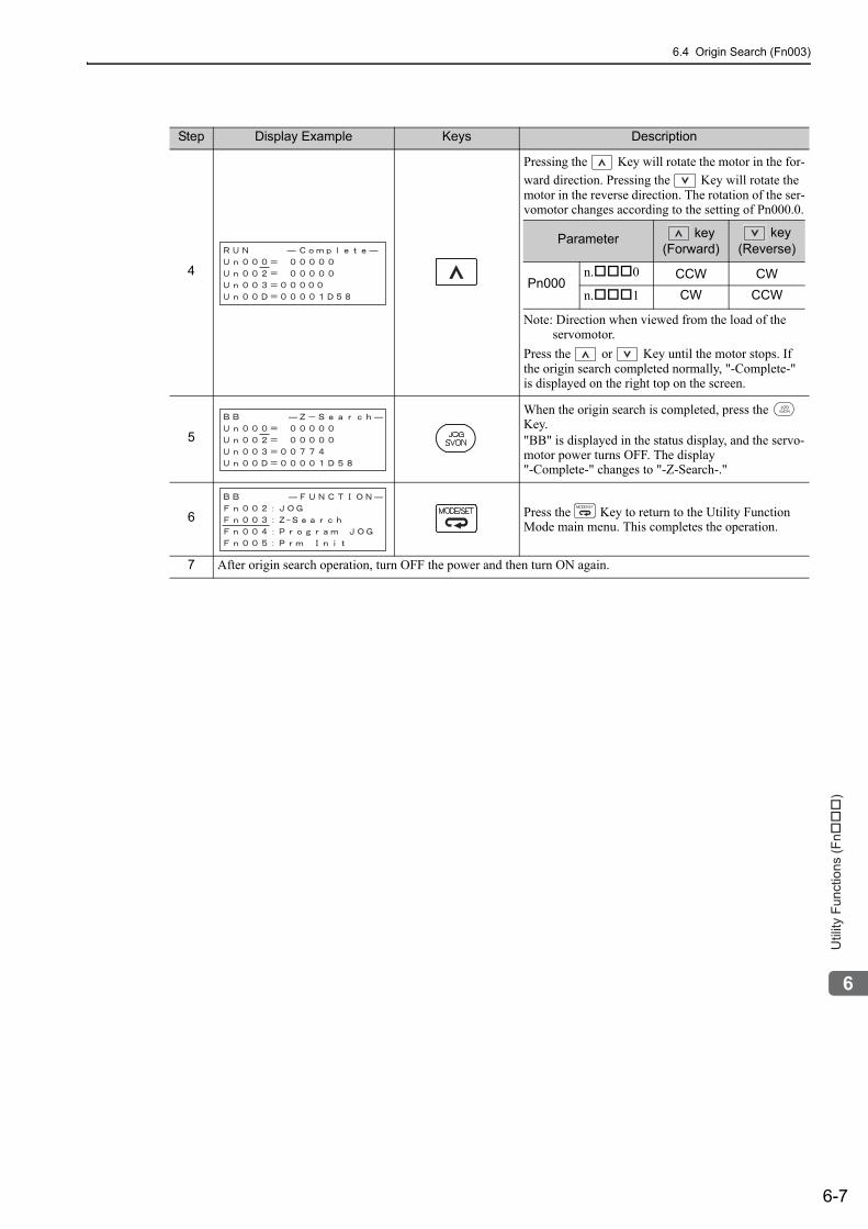
6.4 Origin Search (Fn003)
6-7
6
Utility
Fu
nctio
ns (
Fn���
)
4
Pressing the Key will rotate the motor in the for-ward direction. Pressing the Key will rotate the motor in the reverse direction. The rotation of the ser-vomotor changes according to the setting of Pn000.0.
Note: Direction when viewed from the load of the servomotor.
Press the or Key until the motor stops. If the origin search completed normally, "-Complete-" is displayed on the right top on the screen.
5
When the origin search is completed, press the Key."BB" is displayed in the status display, and the servo-motor power turns OFF. The display "-Complete-" changes to "-Z-Search-."
6 Press the Key to return to the Utility Function Mode main menu. This completes the operation.
7 After origin search operation, turn OFF the power and then turn ON again.
Step Display Example Keys Description
Parameter key(Forward)
key(Reverse)
Pn000n. 0 CCW CWn. 1 CW CCW
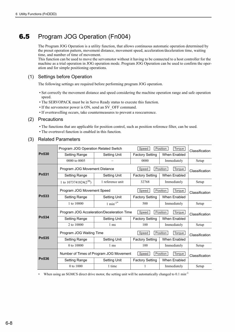
6 Utility Functions (Fn )
6-8
6.5 Program JOG Operation (Fn004)The Program JOG Operation is a utility function, that allows continuous automatic operation determined by the preset operation pattern, movement distance, movement speed, acceleration/deceleration time, waiting time, and number of time of movement.This function can be used to move the servomotor without it having to be connected to a host controller for the machine as a trial operation in JOG operation mode. Program JOG Operation can be used to confirm the oper-ation and for simple positioning operations.
(1) Settings before OperationThe following settings are required before performing program JOG operation.
• Set correctly the movement distance and speed considering the machine operation range and safe operation speed.
• The SERVOPACK must be in Servo Ready status to execute this function.• If the servomotor power is ON, send an SV_OFF command.• If overtravelling occurs, take countermeasures to prevent a reoccurrence.
(2) Precautions• The functions that are applicable for position control, such as position reference filter, can be used.• The overtravel function is enabled in this function.
(3) Related Parameters
∗ When using an SGMCS direct drive motor, the setting unit will be automatically changed to 0.1 min-1
Pn530Program JOG Operation Related Switch
ClassificationSetting Range Setting Unit Factory Setting When Enabled
0000 to 0005 − 0000 Immediately Setup
Pn531Program JOG Movement Distance Classification
Setting Range Setting Unit Factory Setting When Enabled
1 to 1073741824(230) 1 reference unit 32768 Immediately Setup
Pn533Program JOG Movement Speed Classification
Setting Range Setting Unit Factory Setting When Enabled
1 to 10000 1 min-1* 500 Immediately Setup
Pn534Program JOG Acceleration/Deceleration Time Classification
Setting Range Setting Unit Factory Setting When Enabled
2 to 10000 1 ms 100 Immediately Setup
Pn535Program JOG Waiting Time Classification
Setting Range Setting Unit Factory Setting When Enabled
0 to 10000 1 ms 100 Immediately Setup
Pn536Number of Times of Program JOG Movement Classification
Setting Range Setting Unit Factory Setting When Enabled
0 to 1000 1 time 1 Immediately Setup
Speed Position Torque
Speed Position Torque
Speed Position Torque
Speed Position Torque
Speed Position Torque
Speed Position Torque
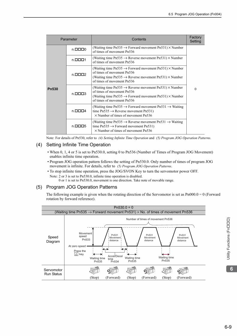
6.5 Program JOG Operation (Fn004)
6-9
6
Utility
Fu
nctio
ns (
Fn���
)
Note: For details of Pn530, refer to (4) Setting Infinite Time Operation and (5) Program JOG Operation Patterns.
(4) Setting Infinite Time Operation• When 0, 1, 4 or 5 is set to Pn530.0, setting 0 to Pn536 (Number of Times of Program JOG Movement)
enables infinite time operation.• Program JOG operation pattern follows the setting of Pn530.0. Only number of times of program JOG
movement is infinite. For details, refer to (5) Program JOG Operation Patterns.• To stop infinite time operation, press the JOG/SVON Key to turn the servomotor power OFF.
Note: 2 or 3 is set to Pn530.0, infinite time operation is disabled.0 or 1 is set to Pn530.0, movement is one direction. Take note of movable range.
(5) Program JOG Operation PatternsThe following example is given when the rotating direction of the Servomotor is set as Pn000.0 = 0 (Forward rotation by forward reference).
Parameter Contents Factory Setting
Pn530
n. 0 (Waiting time Pn535 → Forward movement Pn531) × Number of times of movement Pn536
0
n. 1 (Waiting time Pn535 → Reverse movement Pn531) × Number of times of movement Pn536
n. 2
(Waiting time Pn535 → Forward movement Pn531) × Number of times of movement Pn536(Waiting time Pn535 → Reverse movement Pn531) × Number of times of movement Pn536
n. 3
(Waiting time Pn535 → Reverse movement Pn531) × Number of times of movement Pn536(Waiting time Pn535 → Forward movement Pn531) × Number of times of movement Pn536
n. 4(Waiting time Pn535 → Forward movement Pn531 → Waiting time Pn535 → Reverse movement Pn531) × Number of times of movement Pn536
n. 5(Waiting time Pn535 → Reverse movement Pn531 → Waiting time Pn535 → Forward movement Pn531) × Number of times of movement Pn536
Pn530.0 = 0(Waiting time Pn535 → Forward movement Pn531) × No. of times of movement Pn536
Speed Diagram
Servomotor Run Status
(Stop) (Forward) (Stop) (Forward) (Stop) (Forward)
Movementspeed
Pn533
Waiting timePn535
Accel/Deceltime Waiting time
Pn534 Pn535Waiting time
Pn535
Number of times of movement Pn536
At zero speed
Movementdistance
Pn531Movementdistance
Pn531Movementdistance
Pn531
key.Press the
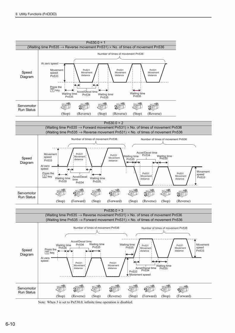
6 Utility Functions (Fn )
6-10
Note: When 3 is set to Pn530.0, infinite time operation is disabled.
Pn530.0 = 1(Waiting time Pn535 → Reverse movement Pn531) × No. of times of movement Pn536
Speed Diagram
Servomotor Run Status
(Stop) (Reverse) (Stop) (Reverse) (Stop) (Reverse)
MovementspeedPn533
Waiting timePn535
Accel/Decel timeWaiting timePn534
Pn535Waiting time
Pn535
Number of times of movement Pn536
At zero speed
Movementdistance
Pn531Movementdistance
Pn531Movementdistance
Pn531
key.Press the
Pn530.0 = 2(Waiting time Pn535 → Forward movement Pn531) × No. of times of movement Pn536 (Waiting time Pn535 → Reverse movement Pn531) × No. of times of movement Pn536
Speed Diagram
Servomotor Run Status
(Stop) (Forward) (Stop) (Forward) (Stop) (Reverse) (Stop) (Reverse)
Movementspeed Movement
distancePn533
Pn531
Waiting timePn535
Accel/Deceltime
Accel/Decel time
Waiting timePn534 Pn535
Waiting time Waiting timePn535
MovementspeedPn533
Pn534Pn535
Number of times of movement Pn536 Number of times of movement Pn536
At zerospeed
Movementdistance
Pn531
Movementdistance
Pn531Movementdistance
Pn531 key.
Press the
Pn530.0 = 3(Waiting time Pn535 → Reverse movement Pn531) × No. of times of movement Pn536 (Waiting time Pn535 → Forward movement Pn531) × No. of times of movement Pn536
Speed Diagram
Servomotor Run Status
(Stop) (Reverse) (Stop) (Reverse) (Stop) (Forward) (Stop) (Forward)
Movement speedPn533
Accel/Decel time
Accel/Decel time
Pn534 Waiting time
Waiting timePn535
MovementspeedPn533
Pn534
Pn535Waiting time
Pn535Waiting time
Pn535
Number of times of movement Pn536 Number of times of movement Pn536
At zerospeed
Movementdistance
Pn531Movementdistance
Pn531
Movementdistance
Pn531Movementdistance
Pn531
key.Press the
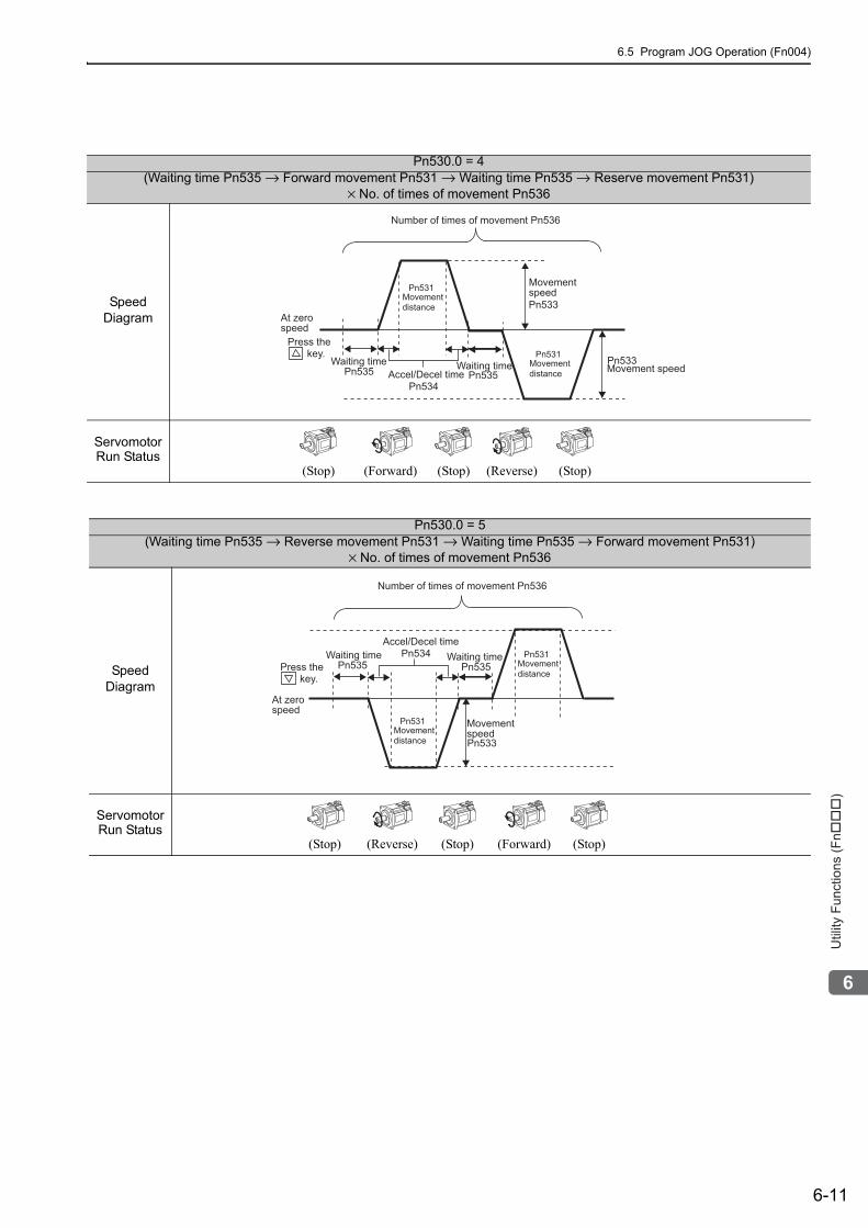
6.5 Program JOG Operation (Fn004)
6-11
6
Utility
Fu
nctio
ns (
Fn���
)
Pn530.0 = 4 (Waiting time Pn535 → Forward movement Pn531 → Waiting time Pn535 → Reserve movement Pn531)
× No. of times of movement Pn536
Speed Diagram
Servomotor Run Status
(Stop) (Forward) (Stop) (Reverse) (Stop)
Movement speedPn533
Accel/Decel timePn534
Pn533
Waiting timePn535 Waiting time
Pn535
Number of times of movement Pn536
Movementspeed
At zerospeed
Movementdistance
Pn531
Movementdistance
Pn531 key.Press the
Pn530.0 = 5(Waiting time Pn535 → Reverse movement Pn531 → Waiting time Pn535 → Forward movement Pn531)
× No. of times of movement Pn536
Speed Diagram
Servomotor Run Status
(Stop) (Reverse) (Stop) (Forward) (Stop)
Movement speedPn533
Accel/Decel timePn534Waiting time
Pn535Waiting time
Pn535
Number of times of movement Pn536
At zerospeed
Movementdistance
Pn531
Movementdistance
Pn531
key.Press the
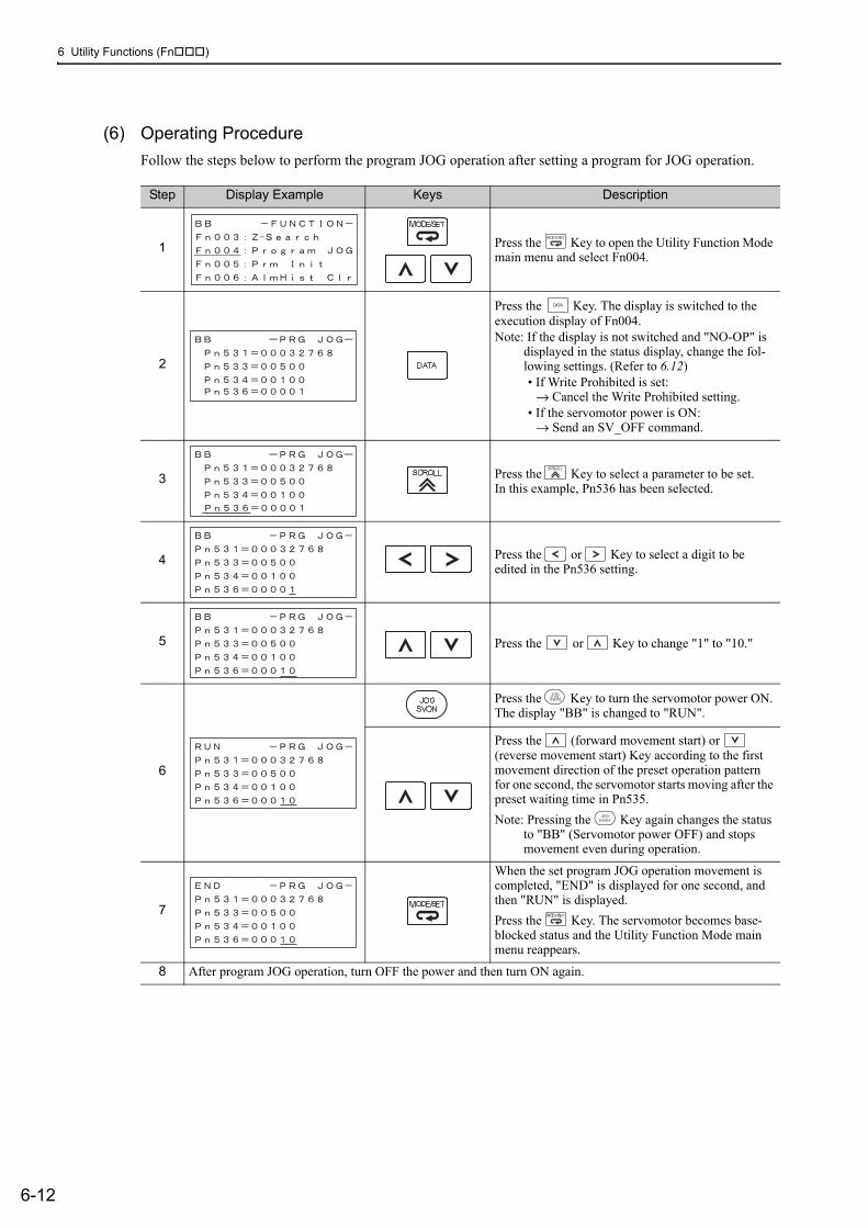
6 Utility Functions (Fn )
6-12
(6) Operating ProcedureFollow the steps below to perform the program JOG operation after setting a program for JOG operation.
Step Display Example Keys Description
1 Press the Key to open the Utility Function Mode main menu and select Fn004.
2
Press the Key. The display is switched to the execution display of Fn004.Note: If the display is not switched and "NO-OP" is
displayed in the status display, change the fol-lowing settings. (Refer to 6.12)• If Write Prohibited is set:
→ Cancel the Write Prohibited setting.• If the servomotor power is ON:
→ Send an SV_OFF command.
3 Press the Key to select a parameter to be set.In this example, Pn536 has been selected.
4 Press the or Key to select a digit to be edited in the Pn536 setting.
5 Press the or Key to change "1" to "10."
6
Press the Key to turn the servomotor power ON. The display "BB" is changed to "RUN".
Press the (forward movement start) or (reverse movement start) Key according to the first movement direction of the preset operation pattern for one second, the servomotor starts moving after the preset waiting time in Pn535.Note: Pressing the Key again changes the status
to "BB" (Servomotor power OFF) and stops movement even during operation.
7
When the set program JOG operation movement is completed, "END" is displayed for one second, and then "RUN" is displayed.Press the Key. The servomotor becomes base-blocked status and the Utility Function Mode main menu reappears.
8 After program JOG operation, turn OFF the power and then turn ON again.
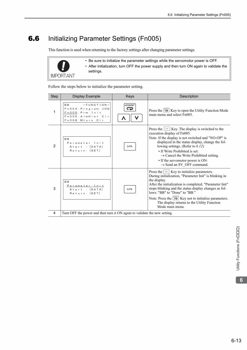
6.6 Initializing Parameter Settings (Fn005)
6-13
6
Utility
Fu
nctio
ns (
Fn���
)
6.6 Initializing Parameter Settings (Fn005)This function is used when returning to the factory settings after changing parameter settings.
Follow the steps below to initialize the parameter setting.
• Be sure to initialize the parameter settings while the servomotor power is OFF.• After initialization, turn OFF the power supply and then turn ON again to validate the
settings.
Step Display Example Keys Description
1 Press the Key to open the Utility Function Mode main menu and select Fn005.
2
Press the Key. The display is switched to the execution display of Fn005.Note: If the display is not switched and "NO-OP" is
displayed in the status display, change the fol-lowing settings. (Refer to 6.12)• If Write Prohibited is set:
→ Cancel the Write Prohibited setting.• If the servomotor power is ON:
→ Send an SV_OFF command.
3
Press the Key to initialize parameters.During initialization, "Parameter Init" is blinking in the display. After the initialization is completed, "Parameter Init" stops blinking and the status display changes as fol-lows: "BB" to "Done" to "BB."Note: Press the Key not to initialize parameters.
The display returns to the Utility Function Mode main menu.
4 Turn OFF the power and then turn it ON again to validate the new setting.
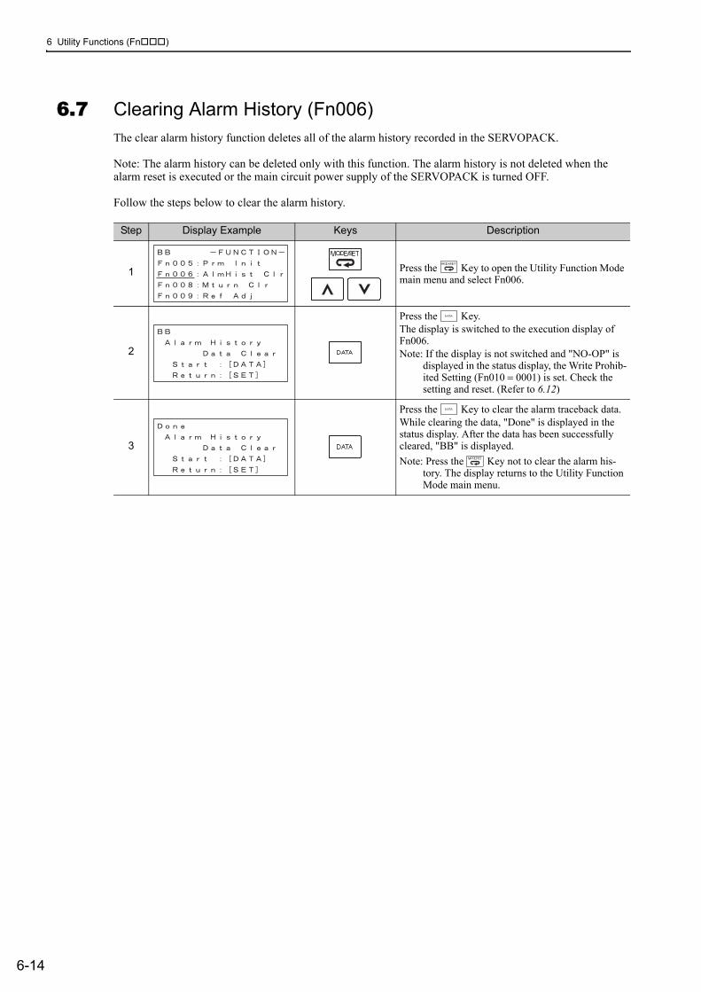
6 Utility Functions (Fn )
6-14
6.7 Clearing Alarm History (Fn006)The clear alarm history function deletes all of the alarm history recorded in the SERVOPACK.
Note: The alarm history can be deleted only with this function. The alarm history is not deleted when the alarm reset is executed or the main circuit power supply of the SERVOPACK is turned OFF.
Follow the steps below to clear the alarm history.
Step Display Example Keys Description
1 Press the Key to open the Utility Function Mode main menu and select Fn006.
2
Press the Key.The display is switched to the execution display of Fn006.Note: If the display is not switched and "NO-OP" is
displayed in the status display, the Write Prohib-ited Setting (Fn010 = 0001) is set. Check the setting and reset. (Refer to 6.12)
3
Press the Key to clear the alarm traceback data.While clearing the data, "Done" is displayed in the status display. After the data has been successfully cleared, "BB" is displayed.Note: Press the Key not to clear the alarm his-
tory. The display returns to the Utility Function Mode main menu.
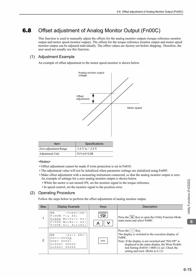
6.8 Offset adjustment of Analog Monitor Output (Fn00C)
6-15
6
Utility
Fu
nctio
ns (
Fn���
)
6.8 Offset adjustment of Analog Monitor Output (Fn00C)This function is used to manually adjust the offsets for the analog monitor outputs (torque reference monitor output and motor speed monitor output). The offsets for the torque reference monitor output and motor speed monitor output can be adjusted individually. The offset values are factory-set before shipping. Therefore, the user need not usually use this function.
(1) Adjustment Example An example of offset adjustment to the motor speed monitor is shown below.
<Notes>• Offset adjustment cannot be made if write protection is set in Fn010.• The adjustment value will not be initialized when parameter settings are initialized using Fn005.• Make offset adjustment with a measuring instrument connected, so that the analog monitor output is zero.
An example of settings for a zero analog monitor output is shown below.• While the motor is not turned ON, set the monitor signal to the torque reference.• In speed control, set the monitor signal to the position error.
(2) Operating ProcedureFollow the steps below to perform the offset adjustment of analog monitor output.
Item Specifications
Zero-adjustment Range -2.4 V to + 2.4 V
Adjustment Unit 18.9 mV/LSB
Analog monitor outputvoltage
Motor speed
Offsetadjustment
Step Display Example Keys Description
1 Press the Key to open the Utility Function Mode main menu and select Fn00C.
2
Press the Key.The display is switched to the execution display of Fn00C.Note: If the display is not switched and "NO-OP" is
displayed in the status display, the Write Prohib-ited Setting (Fn010 = 0001) is set. Check the setting and reset. (Refer to 6.12)
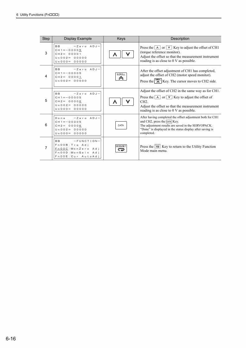
6 Utility Functions (Fn )
6-16
3Press the or Key to adjust the offset of CH1 (torque reference monitor).Adjust the offset so that the measurement instrument reading is as close to 0 V as possible.
4After the offset adjustment of CH1 has completed, adjust the offset of CH2 (motor speed monitor).
Press the Key. The cursor moves to CH2 side.
5
Adjust the offset of CH2 in the same way as for CH1.
Press the or Key to adjust the offset of CH2.Adjust the offset so that the measurement instrument reading is as close to 0 V as possible.
6
After having completed the offset adjustment both for CH1 and CH2, press the Key.The adjustment results are saved in the SERVOPACK. “Done” is displayed in the status display after saving is completed.
7 Press the Key to return to the Utility Function Mode main menu.
Step Display Example Keys Description
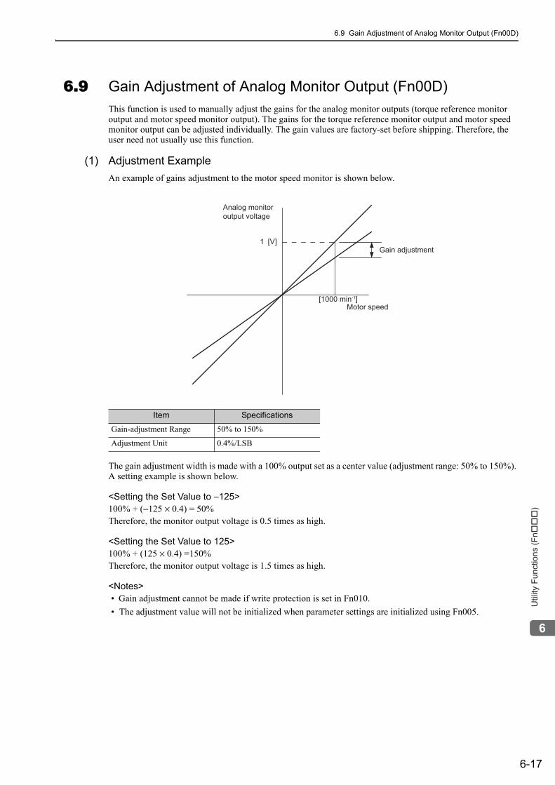
6.9 Gain Adjustment of Analog Monitor Output (Fn00D)
6-17
6
Utility
Fu
nctio
ns (
Fn���
)
6.9 Gain Adjustment of Analog Monitor Output (Fn00D)This function is used to manually adjust the gains for the analog monitor outputs (torque reference monitor output and motor speed monitor output). The gains for the torque reference monitor output and motor speed monitor output can be adjusted individually. The gain values are factory-set before shipping. Therefore, the user need not usually use this function.
(1) Adjustment Example An example of gains adjustment to the motor speed monitor is shown below.
The gain adjustment width is made with a 100% output set as a center value (adjustment range: 50% to 150%). A setting example is shown below.
<Setting the Set Value to −125>100% + (−125 × 0.4) = 50%Therefore, the monitor output voltage is 0.5 times as high.
<Setting the Set Value to 125>100% + (125 × 0.4) =150%Therefore, the monitor output voltage is 1.5 times as high.
<Notes>• Gain adjustment cannot be made if write protection is set in Fn010.• The adjustment value will not be initialized when parameter settings are initialized using Fn005.
Item Specifications
Gain-adjustment Range 50% to 150%
Adjustment Unit 0.4%/LSB
Analog monitor output voltage
Gain adjustment
Motor speed
1 [V]
[1000 min-1]
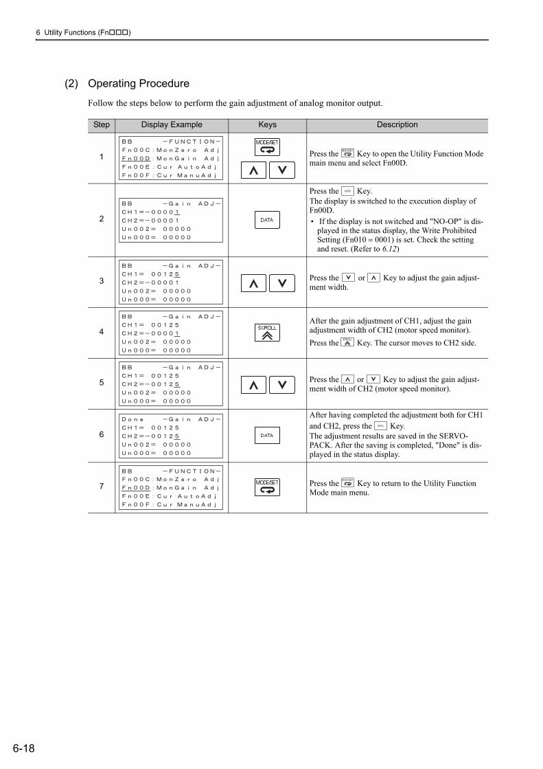
6 Utility Functions (Fn )
6-18
(2) Operating Procedure
Follow the steps below to perform the gain adjustment of analog monitor output.
Step Display Example Keys Description
1 Press the Key to open the Utility Function Mode main menu and select Fn00D.
2
Press the Key.The display is switched to the execution display of Fn00D.• If the display is not switched and "NO-OP" is dis-
played in the status display, the Write Prohibited Setting (Fn010 = 0001) is set. Check the setting and reset. (Refer to 6.12)
3 Press the or Key to adjust the gain adjust-ment width.
4After the gain adjustment of CH1, adjust the gain adjustment width of CH2 (motor speed monitor).Press the Key. The cursor moves to CH2 side.
5 Press the or Key to adjust the gain adjust-ment width of CH2 (motor speed monitor).
6
After having completed the adjustment both for CH1 and CH2, press the Key.The adjustment results are saved in the SERVO-PACK. After the saving is completed, "Done" is dis-played in the status display.
7 Press the Key to return to the Utility Function Mode main menu.
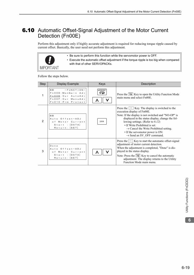
6.10 Automatic Offset-Signal Adjustment of the Motor Current Detection (Fn00E)
6-19
6
Utility
Fu
nctio
ns (
Fn���
)
6.10 Automatic Offset-Signal Adjustment of the Motor Current Detection (Fn00E)Perform this adjustment only if highly accurate adjustment is required for reducing torque ripple caused by current offset. Basically, the user need not perform this adjustment.
Follow the steps below.
• Be sure to perform this function while the servomotor power is OFF.• Execute the automatic offset adjustment if the torque ripple is too big when compared
with that of other SERVOPACKs.
Step Display Example Keys Description
1 Press the Key to open the Utility Function Mode main menu and select Fn00E.
2
Press the Key. The display is switched to the execution display of Fn00E.Note: If the display is not switched and "NO-OP" is
displayed in the status display, change the fol-lowing settings. (Refer to 6.12)• If Write Prohibited is set:
→ Cancel the Write Prohibited setting.• If the servomotor power is ON:
→ Send an SV_OFF command.
3
Press the Key to start the automatic offset-signal adjustment of motor current detection.When the adjustment is completed, "Done" is dis-played in the status display.Note: Press the Key to cancel the automatic
adjustment. The display returns to the Utility Function Mode main menu.
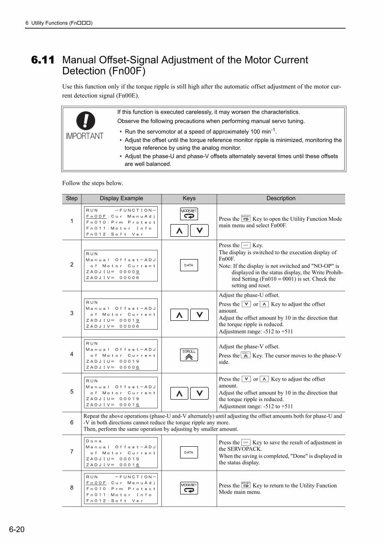
6 Utility Functions (Fn )
6-20
6.11 Manual Offset-Signal Adjustment of the Motor Current Detection (Fn00F)Use this function only if the torque ripple is still high after the automatic offset adjustment of the motor cur-rent detection signal (Fn00E).
Follow the steps below.
If this function is executed carelessly, it may worsen the characteristics.Observe the following precautions when performing manual servo tuning.
• Run the servomotor at a speed of approximately 100 min-1.• Adjust the offset until the torque reference monitor ripple is minimized, monitoring the
torque reference by using the analog monitor. • Adjust the phase-U and phase-V offsets alternately several times until these offsets
are well balanced.
Step Display Example Keys Description
1 Press the Key to open the Utility Function Mode main menu and select Fn00F.
2
Press the Key.The display is switched to the execution display of Fn00F.Note: If the display is not switched and "NO-OP" is
displayed in the status display, the Write Prohib-ited Setting (Fn010 = 0001) is set. Check the setting and reset.
3
Adjust the phase-U offset.Press the or Key to adjust the offset amount.Adjust the offset amount by 10 in the direction that the torque ripple is reduced.Adjustment range: -512 to +511
4Adjust the phase-V offset.Press the Key. The cursor moves to the phase-V side.
5
Press the or Key to adjust the offset amount.Adjust the offset amount by 10 in the direction that the torque ripple is reduced. Adjustment range: -512 to +511
6Repeat the above operations (phase-U and-V alternately) until adjusting the offset amounts both for phase-U and -V in both directions cannot reduce the torque ripple any more.Then, perform the same operation by adjusting by smaller amount.
7Press the Key to save the result of adjustment in the SERVOPACK.When the saving is completed, "Done" is displayed in the status display.
8 Press the Key to return to the Utility Function Mode main menu.
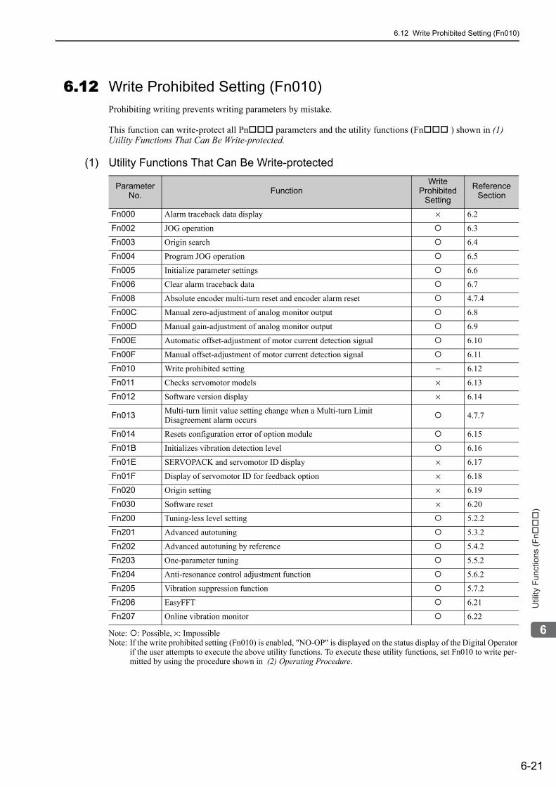
6.12 Write Prohibited Setting (Fn010)
6-21
6
Utility
Fu
nctio
ns (
Fn���
)
6.12 Write Prohibited Setting (Fn010)Prohibiting writing prevents writing parameters by mistake.
This function can write-protect all Pn parameters and the utility functions (Fn ) shown in (1) Utility Functions That Can Be Write-protected.
(1) Utility Functions That Can Be Write-protected
Note: : Possible, ×: ImpossibleNote: If the write prohibited setting (Fn010) is enabled, "NO-OP" is displayed on the status display of the Digital Operator
if the user attempts to execute the above utility functions. To execute these utility functions, set Fn010 to write per-mitted by using the procedure shown in (2) Operating Procedure.
Parameter No. Function
WriteProhibited
Setting
Reference Section
Fn000 Alarm traceback data display × 6.2
Fn002 JOG operation 6.3
Fn003 Origin search 6.4
Fn004 Program JOG operation 6.5
Fn005 Initialize parameter settings 6.6
Fn006 Clear alarm traceback data 6.7
Fn008 Absolute encoder multi-turn reset and encoder alarm reset 4.7.4
Fn00C Manual zero-adjustment of analog monitor output 6.8
Fn00D Manual gain-adjustment of analog monitor output 6.9
Fn00E Automatic offset-adjustment of motor current detection signal 6.10
Fn00F Manual offset-adjustment of motor current detection signal 6.11
Fn010 Write prohibited setting − 6.12
Fn011 Checks servomotor models × 6.13
Fn012 Software version display × 6.14
Fn013 Multi-turn limit value setting change when a Multi-turn LimitDisagreement alarm occurs 4.7.7
Fn014 Resets configuration error of option module 6.15
Fn01B Initializes vibration detection level 6.16
Fn01E SERVOPACK and servomotor ID display × 6.17
Fn01F Display of servomotor ID for feedback option × 6.18
Fn020 Origin setting × 6.19
Fn030 Software reset × 6.20
Fn200 Tuning-less level setting 5.2.2
Fn201 Advanced autotuning 5.3.2
Fn202 Advanced autotuning by reference 5.4.2
Fn203 One-parameter tuning 5.5.2
Fn204 Anti-resonance control adjustment function 5.6.2
Fn205 Vibration suppression function 5.7.2
Fn206 EasyFFT 6.21
Fn207 Online vibration monitor 6.22
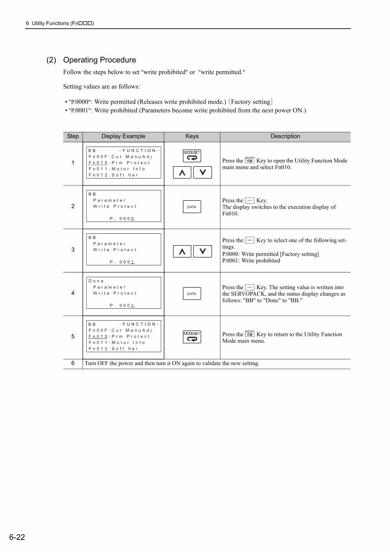
6 Utility Functions (Fn )
6-22
(2) Operating ProcedureFollow the steps below to set "write prohibited" or "write permitted."
Setting values are as follows:
• "P.0000": Write permitted (Releases write prohibited mode.) [Factory setting]• "P.0001": Write prohibited (Parameters become write prohibited from the next power ON.)
Step Display Example Keys Description
1 Press the Key to open the Utility Function Mode main menu and select Fn010.
2Press the Key. The display switches to the execution display of Fn010.
3Press the Key to select one of the following set-tings.P.0000: Write permitted [Factory setting]P.0001: Write prohibited
4Press the Key. The setting value is written into the SERVOPACK, and the status display changes as follows: "BB" to "Done" to "BB."
5 Press the Key to return to the Utility Function Mode main menu.
6 Turn OFF the power and then turn it ON again to validate the new setting.
B B − F U N C T I O N −F n 0 0 F : C u r M a n u A d j
F n 0 1 0 : P r m P r o t e c t
F n 0 1 1 : M o t o r I n f o
F n 0 1 2 : S o f t V e r
B B
P a r a m e t e r
W r i t e P r o t e c t
P . 0 0 0 0
B B
P a r a m e t e r
W r i t e P r o t e c t
P . 0 0 0 1
D o n e
P a r a m e t e r
W r i t e P r o t e c t
P . 0 0 0 1
B B − F U N C T I O N −F n 0 0 F : C u r M a n u A d j
F n 0 1 0 : P r m P r o t e c t
F n 0 1 1 : M o t o r I n f o
F n 0 1 2 : S o f t V e r
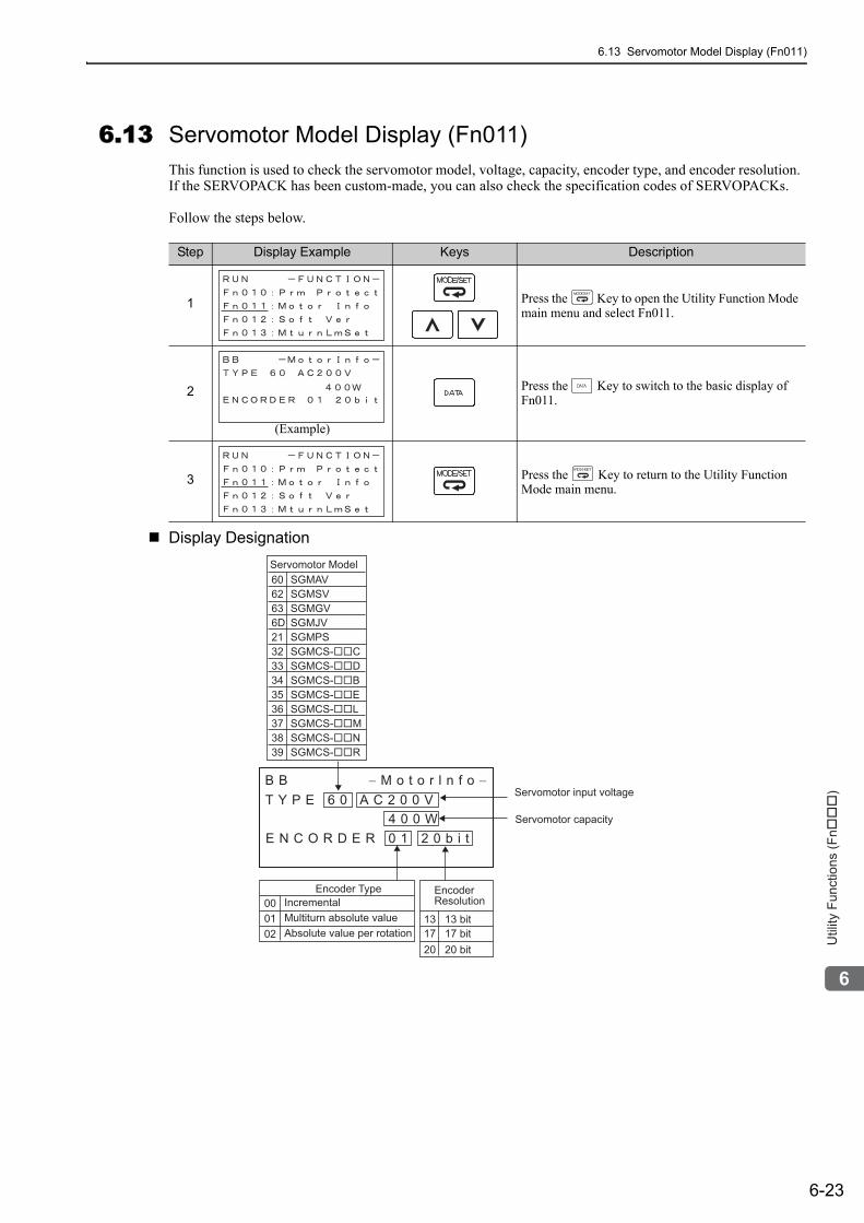
6.13 Servomotor Model Display (Fn011)
6-23
6
Utility
Fu
nctio
ns (
Fn���
)
6.13 Servomotor Model Display (Fn011)This function is used to check the servomotor model, voltage, capacity, encoder type, and encoder resolution. If the SERVOPACK has been custom-made, you can also check the specification codes of SERVOPACKs.
Follow the steps below.
Display Designation
Step Display Example Keys Description
1 Press the Key to open the Utility Function Mode main menu and select Fn011.
2 Press the Key to switch to the basic display of Fn011.
3 Press the Key to return to the Utility Function Mode main menu.
(Example)
Servomotor capacity
Servomotor input voltage
6062636D213233343536373839
SGMAVSGMSVSGMGVSGMJVSGMPSSGMCS-��CSGMCS-��DSGMCS-��BSGMCS-��ESGMCS-��LSGMCS-��MSGMCS-��NSGMCS-��R
00 01
E N C O R D E R 0 1 2 0 b i t
B B − M o t o r l n f o −T Y P E 6 0 A C 2 0 0 V
4 0 0 W
Servomotor Model
Encoder TypeIncrementalMultiturn absolute valueAbsolute value per rotation02 17 17 bit
20 20 bit
13 13 bit
EncoderResolution
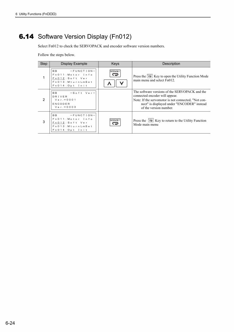
6 Utility Functions (Fn )
6-24
6.14 Software Version Display (Fn012)Select Fn012 to check the SERVOPACK and encoder software version numbers.
Follow the steps below.
Step Display Example Keys Description
1 Press the Key to open the Utility Function Mode main menu and select Fn012.
2
The software versions of the SERVOPACK and the connected encoder will appear.Note: If the servomotor is not connected, "Not con-
nect" is displayed under "ENCODER" instead of the version number.
3 Press the Key to return to the Utility Function Mode main menu
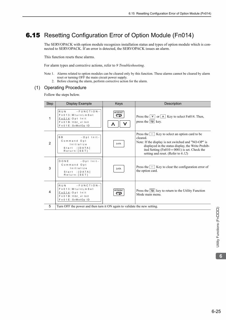
6.15 Resetting Configuration Error of Option Module (Fn014)
6-25
6
Utility
Fu
nctio
ns (
Fn���
)
6.15 Resetting Configuration Error of Option Module (Fn014)The SERVOPACK with option module recognizes installation status and types of option module which is con-nected to SERVOPACK. If an error is detected, the SERVOPACK issues an alarm.
This function resets these alarms.
For alarm types and corrective actions, refer to 9 Troubleshooting.
Note 1. Alarms related to option modules can be cleared only by this function. These alarms cannot be cleared by alarm reset or turning OFF the main circuit power supply.
2. Before clearing the alarm, perform corrective action for the alarm.
(1) Operating ProcedureFollow the steps below.
Step Display Example Keys Description
1 Press the or Key to select Fn014. Then, press the key.
2
Press the Key to select an option card to be cleared.Note: If the display is not switched and "NO-OP" is
displayed in the status display, the Write Prohib-ited Setting (Fn010 = 0001) is set. Check the setting and reset. (Refer to 6.12)
3 Press the Key to clear the configuration error of the option card.
4 Press the key to return to the Utility Function Mode main menu.
5 Turn OFF the power and then turn it ON again to validate the new setting.
R U N − F U N C T I O N −F n 0 1 3 : M t u r n L m S e t
F n 0 1 4 : O p t I n i t
F n 0 1 B : V i b l − v l I n i t
F n 0 1 E : S v M o t O p I D
B B − O p t I n i t −C o m m a n d O p t
I n i t i a l i z eS t a r t : [ D A T A ]R e t u r n : [ S E T ]
S t a r t : [ D A T A ]R e t u r n : [ S E T ]
D O N E − O p t I n i t −C o m m a n d O p t
I n i t i a l i z e
R U N − F U N C T I O N −F n 0 1 3 : M t u r n L m S e t
F n 0 1 4 : O p t I n i t
F n 0 1 B : V i b l − v l I n i t
F n 0 1 E : S v M o t O p I D
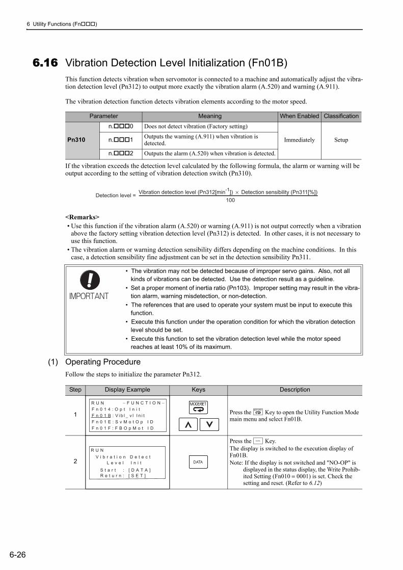
6 Utility Functions (Fn )
6-26
6.16 Vibration Detection Level Initialization (Fn01B)This function detects vibration when servomotor is connected to a machine and automatically adjust the vibra-tion detection level (Pn312) to output more exactly the vibration alarm (A.520) and warning (A.911).
The vibration detection function detects vibration elements according to the motor speed.
If the vibration exceeds the detection level calculated by the following formula, the alarm or warning will be output according to the setting of vibration detection switch (Pn310).
<Remarks>• Use this function if the vibration alarm (A.520) or warning (A.911) is not output correctly when a vibration
above the factory setting vibration detection level (Pn312) is detected. In other cases, it is not necessary to use this function.
• The vibration alarm or warning detection sensibility differs depending on the machine conditions. In this case, a detection sensibility fine adjustment can be set in the detection sensibility Pn311.
(1) Operating ProcedureFollow the steps to initialize the parameter Pn312.
Parameter Meaning When Enabled Classification
Pn310
n. 0 Does not detect vibration (Factory setting)
Immediately Setupn. 1 Outputs the warning (A.911) when vibration is detected.
n. 2 Outputs the alarm (A.520) when vibration is detected.
• The vibration may not be detected because of improper servo gains. Also, not all kinds of vibrations can be detected. Use the detection result as a guideline.
• Set a proper moment of inertia ratio (Pn103). Improper setting may result in the vibra-tion alarm, warning misdetection, or non-detection.
• The references that are used to operate your system must be input to execute this function.
• Execute this function under the operation condition for which the vibration detection level should be set.
• Execute this function to set the vibration detection level while the motor speed reaches at least 10% of its maximum.
Detection level =Vibration detection level (Pn312[min
-1]) × Detection sensibility (Pn311[%])
100
Step Display Example Keys Description
1 Press the Key to open the Utility Function Mode main menu and select Fn01B.
2
Press the Key.The display is switched to the execution display of Fn01B.Note: If the display is not switched and "NO-OP" is
displayed in the status display, the Write Prohib-ited Setting (Fn010 = 0001) is set. Check the setting and reset. (Refer to 6.12)
R U N − F U N C T I O N −F n 0 1 4 : O p t I n i t
F n 0 1 B : V i b l − v l I n i t
F n 0 1 E : S v M o t O p I D
F n 0 1 F : F B O p M o t I D
L e v e l I n i t
R U N
V i b r a t i o n D e t e c t
S t a r t : [ D A T A ]
R e t u r n : [ S E T ]
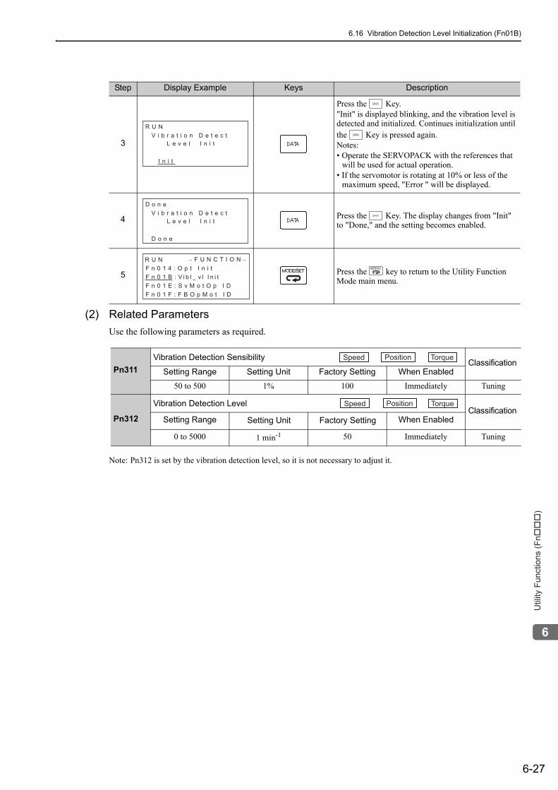
6.16 Vibration Detection Level Initialization (Fn01B)
6-27
6
Utility
Fu
nctio
ns (
Fn���
)
(2) Related ParametersUse the following parameters as required.
Note: Pn312 is set by the vibration detection level, so it is not necessary to adjust it.
3
Press the Key."Init" is displayed blinking, and the vibration level is detected and initialized. Continues initialization until the Key is pressed again.Notes:• Operate the SERVOPACK with the references that
will be used for actual operation.• If the servomotor is rotating at 10% or less of the
maximum speed, "Error " will be displayed.
4 Press the Key. The display changes from "Init" to "Done," and the setting becomes enabled.
5 Press the key to return to the Utility Function Mode main menu.
Step Display Example Keys Description
L e v e l I n i t
R U N
V i b r a t i o n D e t e c t
I n i t
L e v e l I n i t
D o n e
V i b r a t i o n D e t e c t
D o n e
R U N − F U N C T I O N −F n 0 1 4 : O p t I n i t
F n 0 1 B : V i b l − v l I n i t
F n 0 1 E : S v M o t O p I D
F n 0 1 F : F B O p M o t I D
Pn311Vibration Detection Sensibility Classification
Setting Range Setting Unit Factory Setting When Enabled
50 to 500 1% 100 Immediately Tuning
Pn312
Vibration Detection Level Classification
Setting Range Setting Unit Factory Setting When Enabled
0 to 5000 1 min-1 50 Immediately Tuning
Speed Position Torque
Speed Position Torque
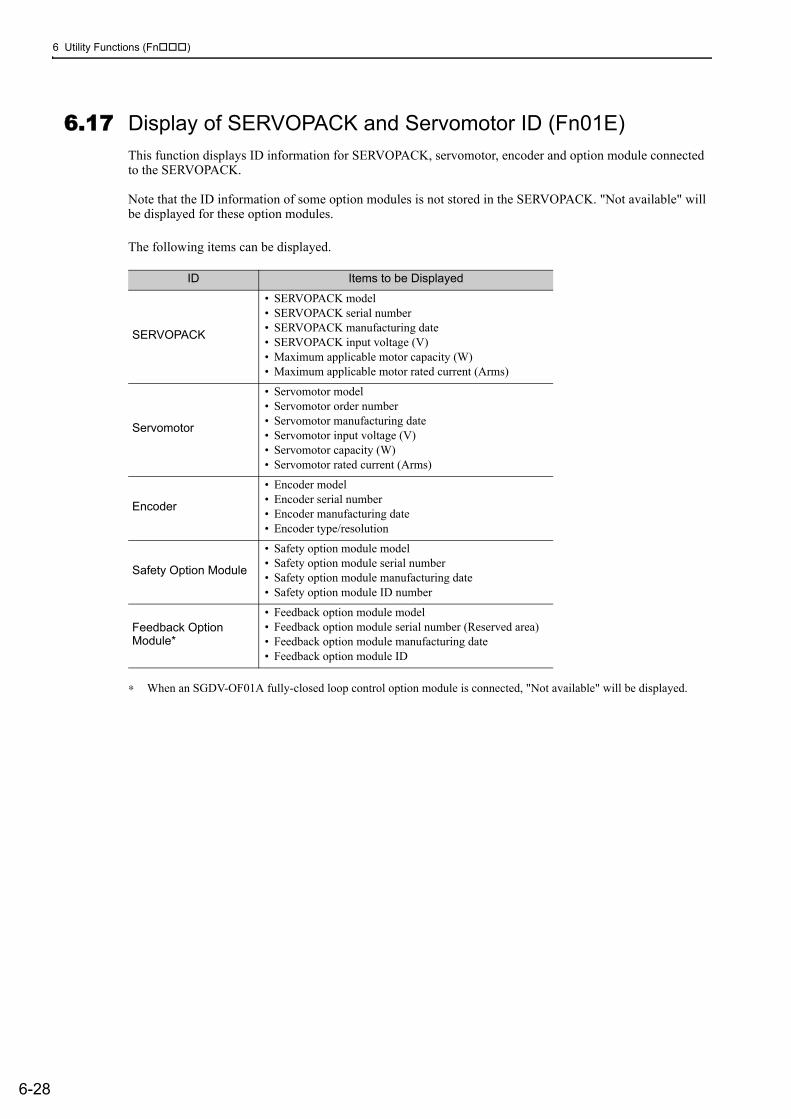
6 Utility Functions (Fn )
6-28
6.17 Display of SERVOPACK and Servomotor ID (Fn01E)This function displays ID information for SERVOPACK, servomotor, encoder and option module connected to the SERVOPACK.
Note that the ID information of some option modules is not stored in the SERVOPACK. "Not available" will be displayed for these option modules.
The following items can be displayed.
∗ When an SGDV-OF01A fully-closed loop control option module is connected, "Not available" will be displayed.
ID Items to be Displayed
SERVOPACK
• SERVOPACK model• SERVOPACK serial number• SERVOPACK manufacturing date• SERVOPACK input voltage (V)• Maximum applicable motor capacity (W)• Maximum applicable motor rated current (Arms)
Servomotor
• Servomotor model• Servomotor order number• Servomotor manufacturing date• Servomotor input voltage (V)• Servomotor capacity (W)• Servomotor rated current (Arms)
Encoder
• Encoder model• Encoder serial number• Encoder manufacturing date• Encoder type/resolution
Safety Option Module
• Safety option module model• Safety option module serial number• Safety option module manufacturing date• Safety option module ID number
Feedback Option Module*
• Feedback option module model• Feedback option module serial number (Reserved area)• Feedback option module manufacturing date• Feedback option module ID
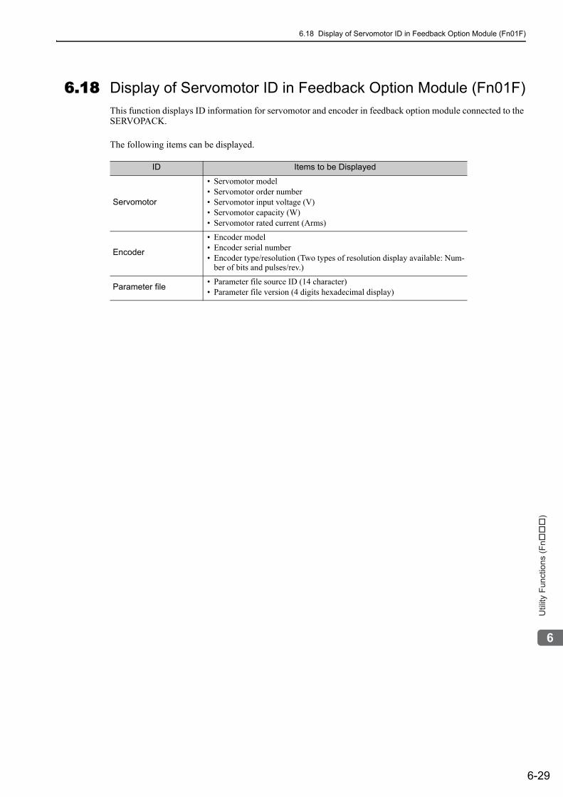
6.18 Display of Servomotor ID in Feedback Option Module (Fn01F)
6-29
6
Utility
Fu
nctio
ns (
Fn���
)
6.18 Display of Servomotor ID in Feedback Option Module (Fn01F)This function displays ID information for servomotor and encoder in feedback option module connected to the SERVOPACK.
The following items can be displayed.
ID Items to be Displayed
Servomotor
• Servomotor model• Servomotor order number• Servomotor input voltage (V)• Servomotor capacity (W)• Servomotor rated current (Arms)
Encoder
• Encoder model• Encoder serial number• Encoder type/resolution (Two types of resolution display available: Num-
ber of bits and pulses/rev.)
Parameter file • Parameter file source ID (14 character)• Parameter file version (4 digits hexadecimal display)
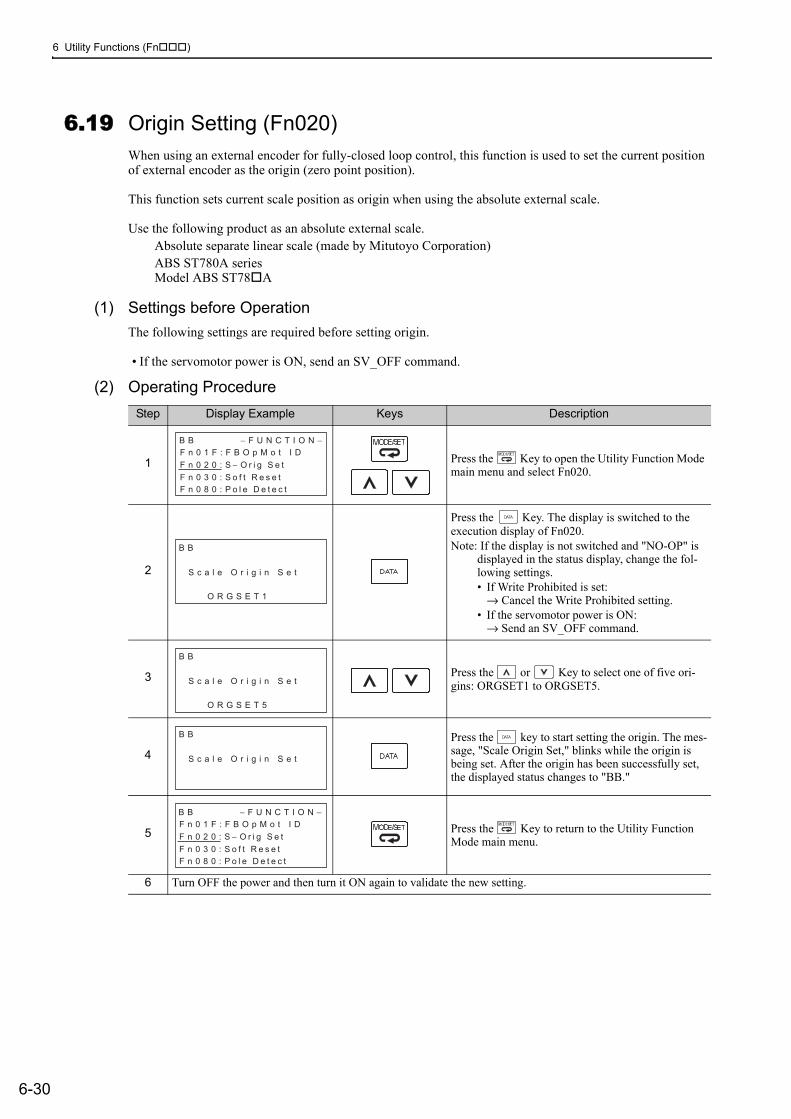
6 Utility Functions (Fn )
6-30
6.19 Origin Setting (Fn020)When using an external encoder for fully-closed loop control, this function is used to set the current position of external encoder as the origin (zero point position).
This function sets current scale position as origin when using the absolute external scale.
Use the following product as an absolute external scale.Absolute separate linear scale (made by Mitutoyo Corporation)ABS ST780A seriesModel ABS ST78 A
(1) Settings before OperationThe following settings are required before setting origin.
• If the servomotor power is ON, send an SV_OFF command.
(2) Operating ProcedureStep Display Example Keys Description
1 Press the Key to open the Utility Function Mode main menu and select Fn020.
2
Press the Key. The display is switched to the execution display of Fn020.Note: If the display is not switched and "NO-OP" is
displayed in the status display, change the fol-lowing settings. • If Write Prohibited is set:
→ Cancel the Write Prohibited setting.• If the servomotor power is ON:
→ Send an SV_OFF command.
3 Press the or Key to select one of five ori-gins: ORGSET1 to ORGSET5.
4Press the key to start setting the origin. The mes-sage, "Scale Origin Set," blinks while the origin is being set. After the origin has been successfully set, the displayed status changes to "BB."
5 Press the Key to return to the Utility Function Mode main menu.
6 Turn OFF the power and then turn it ON again to validate the new setting.
B B − F U N C T I O N −F n 0 1 F : F B O p M o t I D
F n 0 2 0 : S − O r i g S e t
F n 0 3 0 : S o f t R e s e t
F n 0 8 0 : P o l e D e t e c t
O R G S E T 1
B B
S c a l e O r i g i n S e t
O R G S E T 5
B B
S c a l e O r i g i n S e t
B B
S c a l e O r i g i n S e t
B B − F U N C T I O N −F n 0 1 F : F B O p M o t I D
F n 0 2 0 : S − O r i g S e t
F n 0 3 0 : S o f t R e s e t
F n 0 8 0 : P o l e D e t e c t
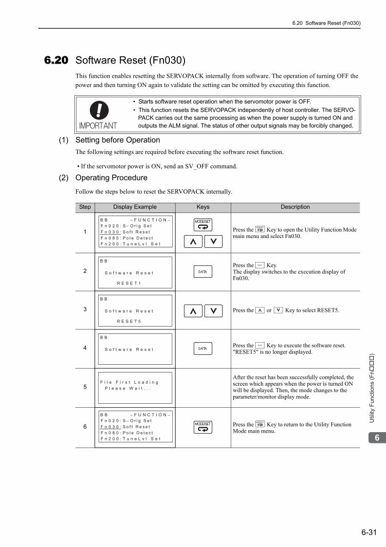
6.20 Software Reset (Fn030)
6-31
6
Utility
Fu
nctio
ns (
Fn���
)
6.20 Software Reset (Fn030)This function enables resetting the SERVOPACK internally from software. The operation of turning OFF the power and then turning ON again to validate the setting can be omitted by executing this function.
(1) Setting before OperationThe following settings are required before executing the software reset function.
• If the servomotor power is ON, send an SV_OFF command.
(2) Operating Procedure
Follow the steps below to reset the SERVOPACK internally.
• Starts software reset operation when the servomotor power is OFF. • This function resets the SERVOPACK independently of host controller. The SERVO-
PACK carries out the same processing as when the power supply is turned ON and outputs the ALM signal. The status of other output signals may be forcibly changed.
Step Display Example Keys Description
1 Press the Key to open the Utility Function Mode main menu and select Fn030.
2Press the Key. The display switches to the execution display of Fn030.
3 Press the or Key to select RESET5.
4 Press the Key to execute the software reset. "RESET5" is no longer displayed.
5
After the reset has been successfully completed, the screen which appears when the power is turned ON will be displayed. Then, the mode changes to the parameter/monitor display mode.
6 Press the Key to return to the Utility Function Mode main menu.
B B − F U N C T I O N −F n 0 2 0 : S − O r i g S e t
F n 0 3 0 : S o f t R e s e t
F n 0 8 0 : P o l e D e t e c t
F n 2 0 0 : T u n e L v l S e t
B B
S o f t w a r e R e s e t
R E S E T 1
B B
S o f t w a r e R e s e t
R E S E T 5
B B
S o f t w a r e R e s e t
F i l e F i r s t L o a d i n g
P l e a s e W a i t . . .
B B − F U N C T I O N −F n 0 2 0 : S − O r i g S e t
F n 0 3 0 : S o f t R e s e t
F n 0 8 0 : P o l e D e t e c t
F n 2 0 0 : T u n e L v l S e t
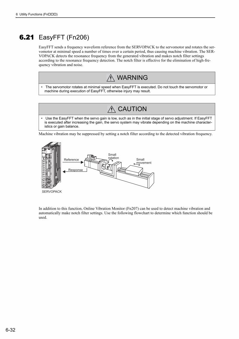
6 Utility Functions (Fn )
6-32
6.21 EasyFFT (Fn206)EasyFFT sends a frequency waveform reference from the SERVOPACK to the servomotor and rotates the ser-vomotor at minimal speed a number of times over a certain period, thus causing machine vibration. The SER-VOPACK detects the resonance frequency from the generated vibration and makes notch filter settings according to the resonance frequency detection. The notch filter is effective for the elimination of high-fre-quency vibration and noise.
Machine vibration may be suppressed by setting a notch filter according to the detected vibration frequency.
In addition to this function, Online Vibration Monitor (Fn207) can be used to detect machine vibration and automatically make notch filter settings. Use the following flowchart to determine which function should be used.
WARNING• The servomotor rotates at minimal speed when EasyFFT is executed. Do not touch the servomotor or
machine during execution of EasyFFT, otherwise injury may result.
CAUTION• Use the EasyFFT when the servo gain is low, such as in the initial stage of servo adjustment. If EasyFFT
is executed after increasing the gain, the servo system may vibrate depending on the machine character-istics or gain balance.
Small
rotationSmall
movement
SERVOPACK
Reference
Response
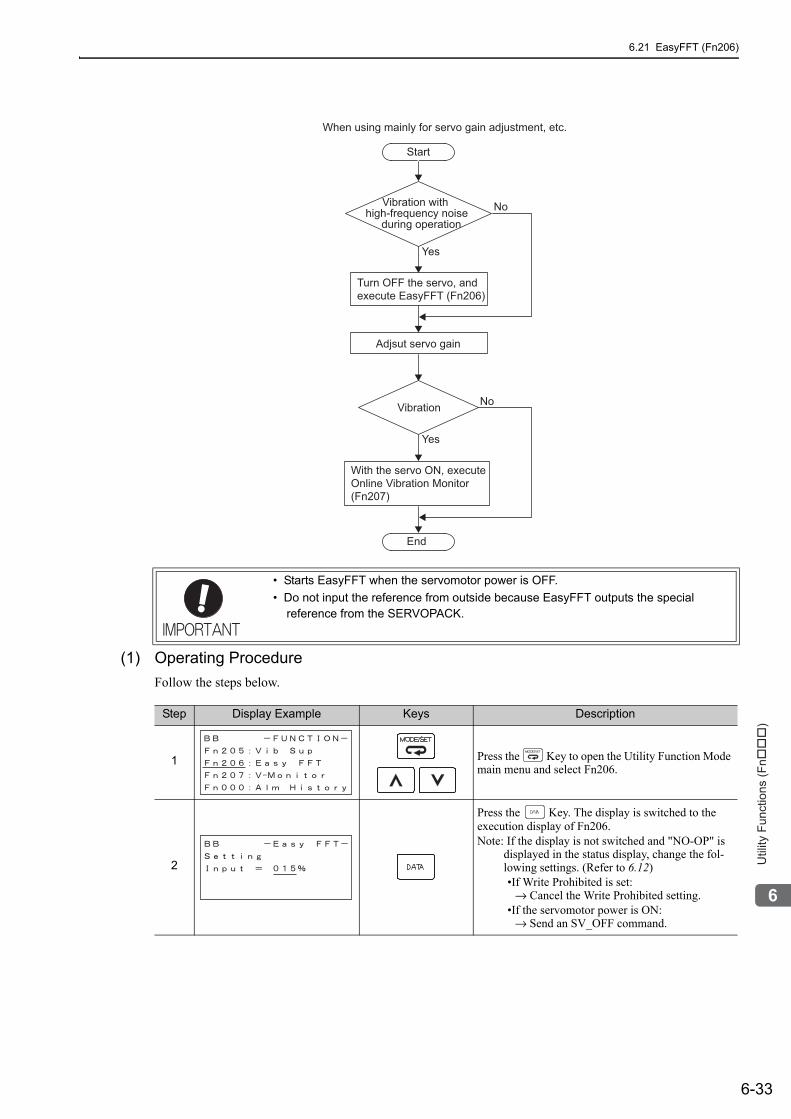
6.21 EasyFFT (Fn206)
6-33
6
Utility
Fu
nctio
ns (
Fn���
)
(1) Operating ProcedureFollow the steps below.
• Starts EasyFFT when the servomotor power is OFF.• Do not input the reference from outside because EasyFFT outputs the special
reference from the SERVOPACK.
Start
When using mainly for servo gain adjustment, etc.
End
Vibration with
high-frequency noise
during operation
Turn OFF the servo, and
execute EasyFFT (Fn206)
No
No
Yes
Yes
Adjsut servo gain
Vibration
With the servo ON, execute
Online Vibration Monitor
(Fn207)
Step Display Example Keys Description
1 Press the Key to open the Utility Function Mode main menu and select Fn206.
2
Press the Key. The display is switched to the execution display of Fn206.Note: If the display is not switched and "NO-OP" is
displayed in the status display, change the fol-lowing settings. (Refer to 6.12)•If Write Prohibited is set:
→ Cancel the Write Prohibited setting.•If the servomotor power is ON:
→ Send an SV_OFF command.
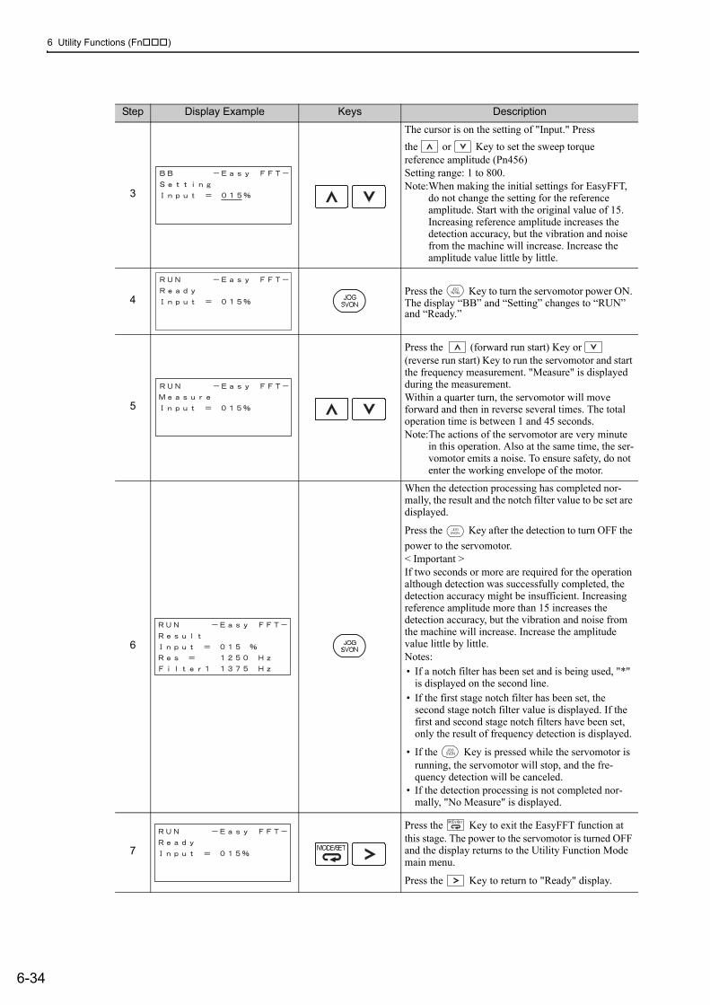
6 Utility Functions (Fn )
6-34
3
The cursor is on the setting of "Input." Press the or Key to set the sweep torque reference amplitude (Pn456)Setting range: 1 to 800.Note:When making the initial settings for EasyFFT,
do not change the setting for the reference amplitude. Start with the original value of 15. Increasing reference amplitude increases the detection accuracy, but the vibration and noise from the machine will increase. Increase the amplitude value little by little.
4Press the Key to turn the servomotor power ON. The display “BB” and “Setting” changes to “RUN” and “Ready.”
5
Press the (forward run start) Key or (reverse run start) Key to run the servomotor and start the frequency measurement. "Measure" is displayed during the measurement.Within a quarter turn, the servomotor will move forward and then in reverse several times. The total operation time is between 1 and 45 seconds.Note:The actions of the servomotor are very minute
in this operation. Also at the same time, the ser-vomotor emits a noise. To ensure safety, do not enter the working envelope of the motor.
6
When the detection processing has completed nor-mally, the result and the notch filter value to be set are displayed.
Press the Key after the detection to turn OFF the power to the servomotor.< Important >If two seconds or more are required for the operation although detection was successfully completed, the detection accuracy might be insufficient. Increasing reference amplitude more than 15 increases the detection accuracy, but the vibration and noise from the machine will increase. Increase the amplitude value little by little.Notes: • If a notch filter has been set and is being used, "*"
is displayed on the second line.• If the first stage notch filter has been set, the
second stage notch filter value is displayed. If the first and second stage notch filters have been set, only the result of frequency detection is displayed.
• If the Key is pressed while the servomotor is running, the servomotor will stop, and the fre-quency detection will be canceled.
• If the detection processing is not completed nor-mally, "No Measure" is displayed.
7
Press the Key to exit the EasyFFT function at this stage. The power to the servomotor is turned OFF and the display returns to the Utility Function Mode main menu.
Press the Key to return to "Ready" display.
Step Display Example Keys Description
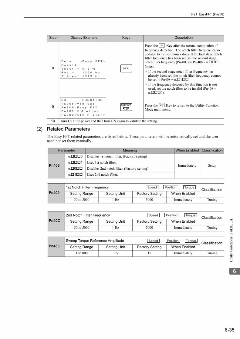
6.21 EasyFFT (Fn206)
6-35
6
Utility
Fu
nctio
ns (
Fn���
)
(2) Related ParametersThe Easy FFT related parameters are listed below. These parameters will be automatically set and the user need not set them manually.
8
Press the Key after the normal completion of frequency detection. The notch filter frequencies are updated to the optimum values. If the first stage notch filter frequency has been set, set the second stage notch filter frequency (Pn 40C) to Pn 408 = n. 1 . Notes:• If the second stage notch filter frequency has
already been set, the notch filter frequency cannot be set in Pn408 = n. 1 .
• If the frequency detected by this function is not used, set the notch filter to be invalid (Pn408 = n. 0).
9 Press the Key to return to the Utility Function Mode main menu.
10 Turn OFF the power and then turn ON again to validate the setting.
Step Display Example Keys Description
Parameter Meaning When Enabled Classification
Pn408
n. 0 Disables 1st notch filter. (Factory setting)
Immediately Setupn. 1 Uses 1st notch filter.
n. 0 Disables 2nd notch filter. (Factory setting)
n. 1 Uses 2nd notch filter.
Pn4091st Notch FIlter Frequency Classification
Setting Range Setting Unit Factory Setting When Enabled
50 to 5000 1 Hz 5000 Immediately Tuning
Pn40C2nd Notch FIlter Frequency Classification
Setting Range Setting Unit Factory Setting When Enabled
50 to 5000 1 Hz 5000 Immediately Tuning
Pn456Sweep Torque Reference Amplitude Classification
Setting Range Setting Unit Factory Setting When Enabled
1 to 800 1% 15 Immediately Tuning
Speed Position Torque
Speed Position Torque
Speed Position Torque
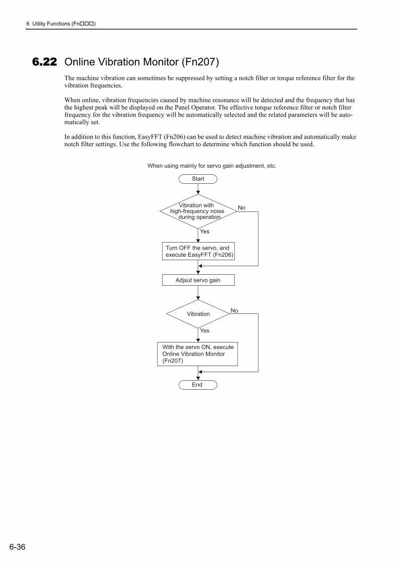
6 Utility Functions (Fn )
6-36
6.22 Online Vibration Monitor (Fn207)The machine vibration can sometimes be suppressed by setting a notch filter or torque reference filter for the vibration frequencies.
When online, vibration frequencies caused by machine resonance will be detected and the frequency that has the highest peak will be displayed on the Panel Operator. The effective torque reference filter or notch filter frequency for the vibration frequency will be automatically selected and the related parameters will be auto-matically set.
In addition to this function, EasyFFT (Fn206) can be used to detect machine vibration and automatically make notch filter settings. Use the following flowchart to determine which function should be used.
Start
When using mainly for servo gain adjustment, etc.
End
Vibration with
high-frequency noise
during operation
Turn OFF the servo, and
execute EasyFFT (Fn206)
No
No
Yes
Yes
Adjsut servo gain
Vibration
With the servo ON, execute
Online Vibration Monitor
(Fn207)
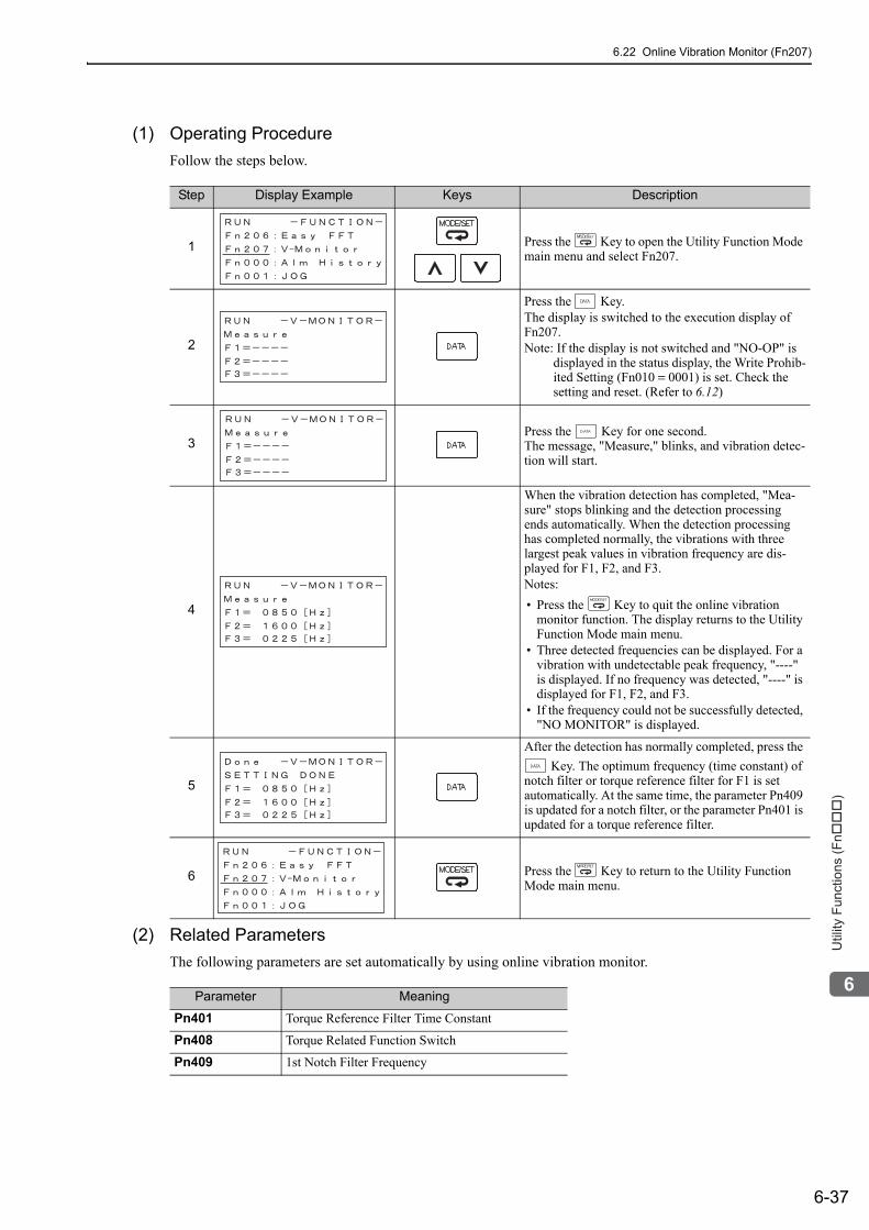
6.22 Online Vibration Monitor (Fn207)
6-37
6
Utility
Fu
nctio
ns (
Fn���
)
(1) Operating Procedure Follow the steps below.
(2) Related ParametersThe following parameters are set automatically by using online vibration monitor.
Step Display Example Keys Description
1 Press the Key to open the Utility Function Mode main menu and select Fn207.
2
Press the Key.The display is switched to the execution display of Fn207.Note: If the display is not switched and "NO-OP" is
displayed in the status display, the Write Prohib-ited Setting (Fn010 = 0001) is set. Check the setting and reset. (Refer to 6.12)
3Press the Key for one second.The message, "Measure," blinks, and vibration detec-tion will start.
4
When the vibration detection has completed, "Mea-sure" stops blinking and the detection processing ends automatically. When the detection processing has completed normally, the vibrations with three largest peak values in vibration frequency are dis-played for F1, F2, and F3.Notes: • Press the Key to quit the online vibration
monitor function. The display returns to the Utility Function Mode main menu.
• Three detected frequencies can be displayed. For a vibration with undetectable peak frequency, "----" is displayed. If no frequency was detected, "----" is displayed for F1, F2, and F3.
• If the frequency could not be successfully detected, "NO MONITOR" is displayed.
5
After the detection has normally completed, press the Key. The optimum frequency (time constant) of
notch filter or torque reference filter for F1 is set automatically. At the same time, the parameter Pn409 is updated for a notch filter, or the parameter Pn401 is updated for a torque reference filter.
6 Press the Key to return to the Utility Function Mode main menu.
Parameter Meaning
Pn401 Torque Reference Filter Time Constant
Pn408 Torque Related Function Switch
Pn409 1st Notch Filter Frequency
7-1
7
Mo
nito
r M
od
es (
Un���
)
7Monitor Modes (Un )
7.1 List of Monitor Modes . . . . . . . . . . . . . . . . . . . . . . . . . . . . . . . . . . . . . . . . .7-2
7.2 Monitor Mode Display . . . . . . . . . . . . . . . . . . . . . . . . . . . . . . . . . . . . . . . .7-3
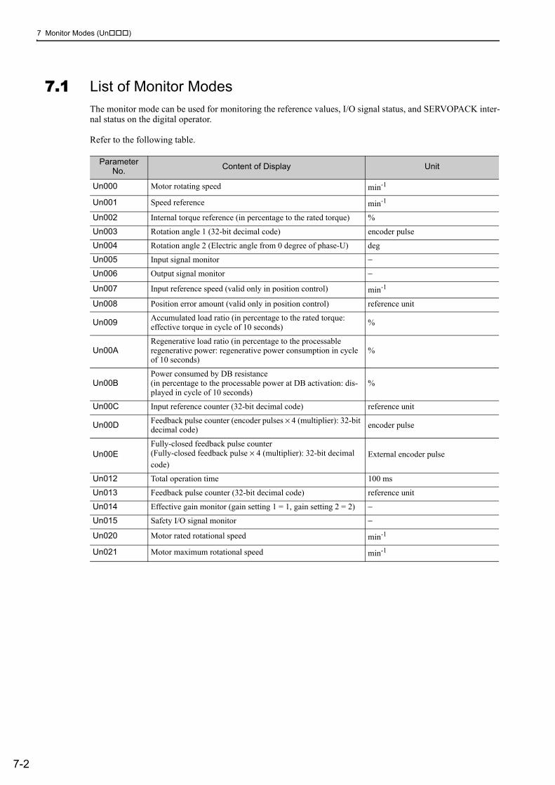
7 Monitor Modes (Un )
7-2
7.1 List of Monitor ModesThe monitor mode can be used for monitoring the reference values, I/O signal status, and SERVOPACK inter-nal status on the digital operator.
Refer to the following table.
Parameter No. Content of Display Unit
Un000 Motor rotating speed min-1
Un001 Speed reference min-1
Un002 Internal torque reference (in percentage to the rated torque) %
Un003 Rotation angle 1 (32-bit decimal code) encoder pulse
Un004 Rotation angle 2 (Electric angle from 0 degree of phase-U) deg
Un005 Input signal monitor −
Un006 Output signal monitor −
Un007 Input reference speed (valid only in position control) min-1
Un008 Position error amount (valid only in position control) reference unit
Un009 Accumulated load ratio (in percentage to the rated torque: effective torque in cycle of 10 seconds) %
Un00ARegenerative load ratio (in percentage to the processable regenerative power: regenerative power consumption in cycle of 10 seconds)
%
Un00BPower consumed by DB resistance(in percentage to the processable power at DB activation: dis-played in cycle of 10 seconds)
%
Un00C Input reference counter (32-bit decimal code) reference unit
Un00D Feedback pulse counter (encoder pulses × 4 (multiplier): 32-bit decimal code) encoder pulse
Un00EFully-closed feedback pulse counter (Fully-closed feedback pulse × 4 (multiplier): 32-bit decimal code)
External encoder pulse
Un012 Total operation time 100 ms
Un013 Feedback pulse counter (32-bit decimal code) reference unit
Un014 Effective gain monitor (gain setting 1 = 1, gain setting 2 = 2) −
Un015 Safety I/O signal monitor −
Un020 Motor rated rotational speed min-1
Un021 Motor maximum rotational speed min-1
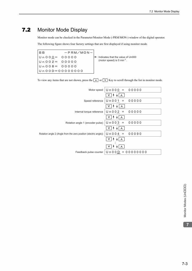
7.2 Monitor Mode Display
7-3
7
Mo
nito
r M
od
es (
Un���
)
7.2 Monitor Mode DisplayMonitor mode can be checked in the Parameter/Monitor Mode (-PRM/MON-) window of the digital operator.
The following figure shows four factory settings that are first displayed if using monitor mode.
To view any items that are not shown, press the or Key to scroll through the list in monitor mode.
Indicates that the value of Un000(motor speed) is 0 min-1.
U n 0 0 0 = 0 0 0 0 0
U n 0 0 1 = 0 0 0 0 0
U n 0 0 2 = 0 0 0 0 0
U n 0 0 3 = 0 0 0 0 0
U n 0 0 4 = 0 0 0 9 0
U n 0 0 D = 0 0 0 0 0 0 0 0
Motor speed
Speed reference
Rotation angle 1 (encoder pulse)
Rotation angle 2 (Angle from the zero position (electric angle))
Feedback pulse counter
Internal torque reference
8-1
8
Fu
lly-c
lose
d L
oo
p C
on
tro
l
8Fully-closed Loop Control
8.1 System Configuration and Connection Example for SERVOPACK with Fully-closed Loop Control . . . . . . . . . . . . . . . . . . . . .8-2
8.1.1 System Configuration . . . . . . . . . . . . . . . . . . . . . . . . . . . . . . . . . . . . . . . . . . . . . . . . . 8-28.1.2 Internal Configuration of Fully-closed Loop Control . . . . . . . . . . . . . . . . . . . . . . . . . . 8-38.1.3 Serial Converter Unit . . . . . . . . . . . . . . . . . . . . . . . . . . . . . . . . . . . . . . . . . . . . . . . . . . 8-48.1.4 Connection Example of External Encoder by Heidenhain . . . . . . . . . . . . . . . . . . . . . 8-68.1.5 Connection Example of External Encoder by Mitutoyo . . . . . . . . . . . . . . . . . . . . . . . . 8-78.1.6 Connection Example of External Encoder by Renishaw . . . . . . . . . . . . . . . . . . . . . . . 8-88.1.7 Encoder Output Pulse Signals from SERVOPACK with a External Encoder by
Renishaw . . . . . . . . . . . . . . . . . . . . . . . . . . . . . . . . . . . . . . . . . . . . . . . . . . . . . . . . . . 8-9
8.2 Settings for Fully-closed Loop Control . . . . . . . . . . . . . . . . . . . . . . . . . . 8-108.2.1 Setting Order . . . . . . . . . . . . . . . . . . . . . . . . . . . . . . . . . . . . . . . . . . . . . . . . . . . . . . . 8-108.2.2 Motor Rotation Direction . . . . . . . . . . . . . . . . . . . . . . . . . . . . . . . . . . . . . . . . . . . . . . 8-118.2.3 Sine Wave Pitch (Frequency) for an External Encoder . . . . . . . . . . . . . . . . . . . . . . . 8-128.2.4 Number of Encoder Output Pulses (PAO, PBO, and PCO) from
the SERVOPACK . . . . . . . . . . . . . . . . . . . . . . . . . . . . . . . . . . . . . . . . . . . . . . . . . . . 8-138.2.5 Absolute External Encoder Reception Sequence . . . . . . . . . . . . . . . . . . . . . . . . . . . 8-148.2.6 Electronic Gear . . . . . . . . . . . . . . . . . . . . . . . . . . . . . . . . . . . . . . . . . . . . . . . . . . . . . 8-178.2.7 Alarm Detection . . . . . . . . . . . . . . . . . . . . . . . . . . . . . . . . . . . . . . . . . . . . . . . . . . . . . 8-178.2.8 Analog Monitor Signal . . . . . . . . . . . . . . . . . . . . . . . . . . . . . . . . . . . . . . . . . . . . . . . . 8-188.2.9 Speed Feedback Method during Fully-closed Loop Control . . . . . . . . . . . . . . . . . . . 8-18
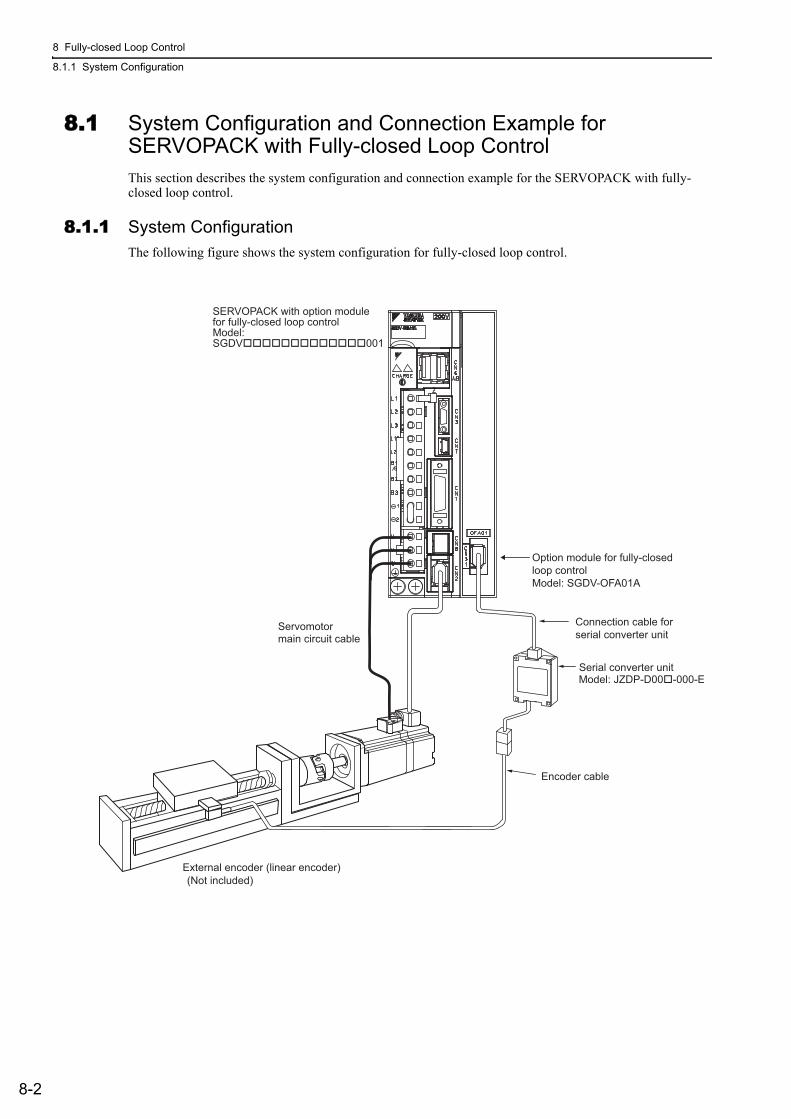
8 Fully-closed Loop Control
8.1.1 System Configuration
8-2
8.1 System Configuration and Connection Example for SERVOPACK with Fully-closed Loop ControlThis section describes the system configuration and connection example for the SERVOPACK with fully-closed loop control.
8.1.1 System ConfigurationThe following figure shows the system configuration for fully-closed loop control.
Serial converter unit
Encoder cable
Connection cable forserial converter unit
External encoder (linear encoder)(Not included)
Servomotormain circuit cable
Model: JZDP-D00�-000-E
SERVOPACK with option modulefor fully-closed loop controlModel:SGDV�������������001
Option module for fully-closedloop controlModel: SGDV-OFA01A
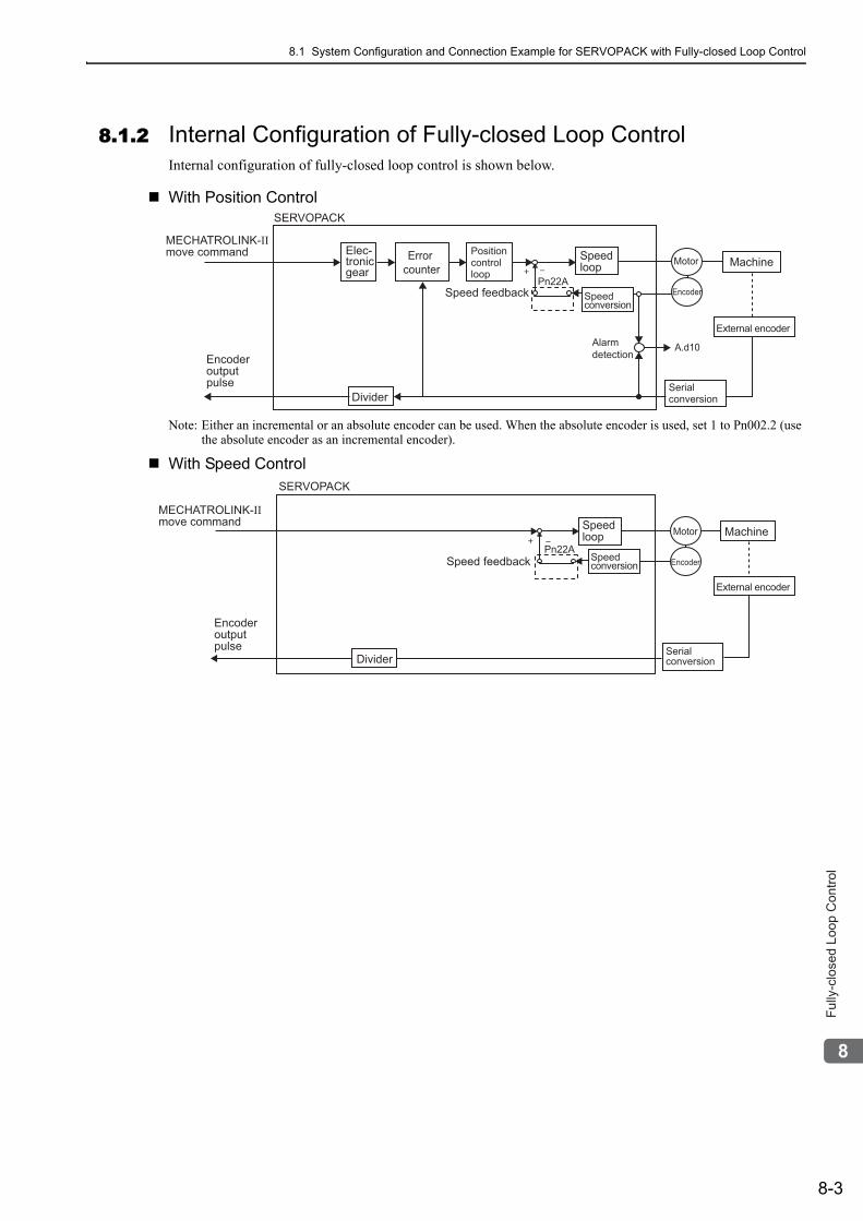
8.1 System Configuration and Connection Example for SERVOPACK with Fully-closed Loop Control
8-3
8
Fu
lly-c
lose
d L
oo
p C
on
tro
l
8.1.2 Internal Configuration of Fully-closed Loop ControlInternal configuration of fully-closed loop control is shown below.
With Position Control
Note: Either an incremental or an absolute encoder can be used. When the absolute encoder is used, set 1 to Pn002.2 (use the absolute encoder as an incremental encoder).
With Speed Control
Elec-tronicgear
MECHATROLINK-IImove command
Encoderoutputpulse
Error counter
Speedloop
Alarmdetection
Divider
Machine
SERVOPACK
Positioncontrolloop
Serialconversion
Motor
A.d10
Encoder
External encoder
Pn22ASpeed conversion
Speed feedback
SERVOPACK
Encoderoutputpulse
Pn22A
Divider
Speedloop MachineMotor
Encoder
External encoder
Speed conversionSpeed feedback
Serialconversion
MECHATROLINK-IImove command
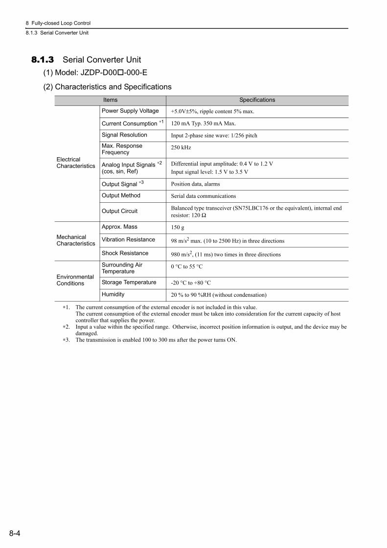
8 Fully-closed Loop Control
8.1.3 Serial Converter Unit
8-4
8.1.3 Serial Converter Unit(1) Model: JZDP-D00 -000-E
(2) Characteristics and Specifications
∗1. The current consumption of the external encoder is not included in this value. The current consumption of the external encoder must be taken into consideration for the current capacity of host controller that supplies the power.
∗2. Input a value within the specified range. Otherwise, incorrect position information is output, and the device may be damaged.
∗3. The transmission is enabled 100 to 300 ms after the power turns ON.
Items Specifications
Electrical Characteristics
Power Supply Voltage +5.0V±5%, ripple content 5% max.
Current Consumption ∗1 120 mA Typ. 350 mA Max.
Signal Resolution Input 2-phase sine wave: 1/256 pitch
Max. ResponseFrequency
250 kHz
Analog Input Signals ∗2
(cos, sin, Ref)Differential input amplitude: 0.4 V to 1.2 VInput signal level: 1.5 V to 3.5 V
Output Signal ∗3 Position data, alarms
Output Method Serial data communications
Output Circuit Balanced type transceiver (SN75LBC176 or the equivalent), internal end resistor: 120 Ω
Mechanical Characteristics
Approx. Mass 150 g
Vibration Resistance 98 m/s2 max. (10 to 2500 Hz) in three directions
Shock Resistance 980 m/s2, (11 ms) two times in three directions
Environmental Conditions
Surrounding Air Temperature
0 °C to 55 °C
Storage Temperature -20 °C to +80 °C
Humidity 20 % to 90 %RH (without condensation)
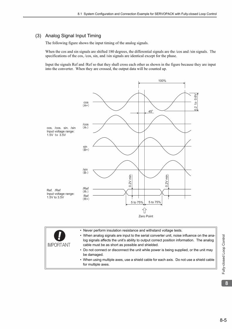
8.1 System Configuration and Connection Example for SERVOPACK with Fully-closed Loop Control
8-5
8
Fu
lly-c
lose
d L
oo
p C
on
tro
l
(3) Analog Signal Input TimingThe following figure shows the input timing of the analog signals.
When the cos and sin signals are shifted 180 degrees, the differential signals are the /cos and /sin signals. The specifications of the cos, /cos, sin, and /sin signals are identical except for the phase.
Input the signals Ref and /Ref so that they shall cross each other as shown in the figure because they are input into the converter. When they are crossed, the output data will be counted up.
• Never perform insulation resistance and withstand voltage tests.• When analog signals are input to the serial converter unit, noise influence on the ana-
log signals affects the unit’s ability to output correct position information. The analog cable must be as short as possible and shielded.
• Do not connect or disconnect the unit while power is being supplied, or the unit may be damaged.
• When using multiple axes, use a shield cable for each axis. Do not use a shield cable for multiple axes.
100%
45
5 to 75% 5 to 75%
0.2
V m
in.
0.2
V m
in.
Zero Point
0.2
0.6
V
cos
A+
/cos
A-
sin
B+
/sin
B-
/Ref
R-
Ref
R+
cos /cos sin /sin
Input voltage range:
1.5V 3.5V
Ref /Ref
Input voltage range:
1.5V to 3.5V
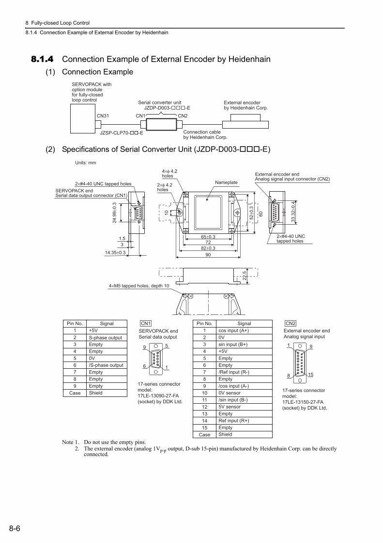
8 Fully-closed Loop Control
8.1.4 Connection Example of External Encoder by Heidenhain
8-6
8.1.4 Connection Example of External Encoder by Heidenhain(1) Connection Example
(2) Specifications of Serial Converter Unit (JZDP-D003- -E)
Note 1. Do not use the empty pins.2. The external encoder (analog 1Vp-p output, D-sub 15-pin) manufactured by Heidenhain Corp. can be directly
connected.
SERVOPACK withoption module for fully-closedloop control Serial converter unit
JZSP-CLP70-��-E Connection cable by Heidenhain Corp.
External encoderby Heidenhain Corp.JZDP-D003- -E
CN31 CN1 CN2
33
.32
±0
.4
24
.99
±0
.3
2×#4-40 UNC
tapped holes
SERVOPACK end
Serial data output connector (CN1)
2×#4-40 UNC tapped holes
4×φ 4.2
holes
2×φ 4.2
holes
4×M5 tapped holes, depth 10
Nameplate
External encoder end
Analog signal input connector (CN2)
1.5
3
14.35±0.3
10
65±0.3
72
82±0.3
90
22
.5
52
±0
.3
60
Units: mm
17-series connectormodel:17LE-13090-27-FA(socket) by DDK Ltd.
17-series connectormodel:17LE-13150-27-FA(socket) by DDK Ltd.
SERVOPACK endSerial data output
External encoder endAnalog signal input
Pin No. Signal+5VS-phase outputEmptyEmpty0V/S-phase outputEmptyEmptyEmptyShield
Pin No. Signalcos input (A+)0V sin input (B+)+5VEmpty
/Ref input (R-)Empty/cos input (A-)0V sensor/sin input (B-)
Ref input (R+)
5V sensor
Empty
Empty
Empty
Shield
1
8
9
6 1
5 9
15
CN1 CN2123456789
Case
123456789
101112131415
Case
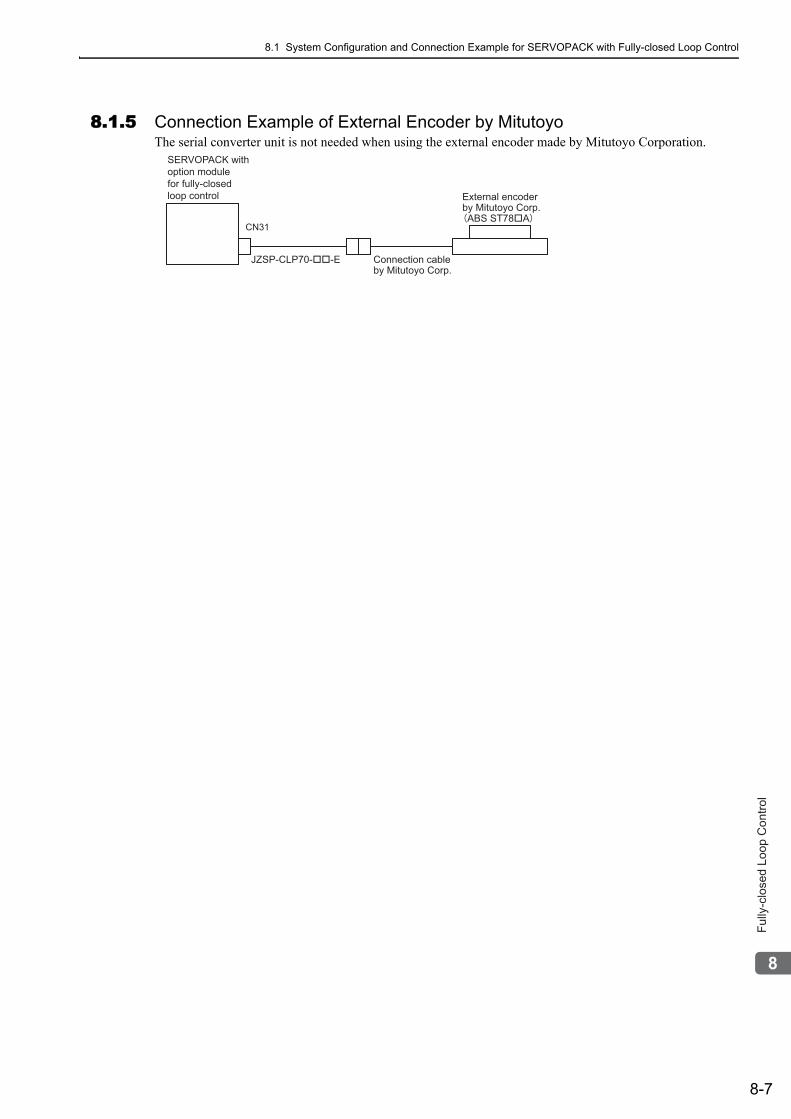
8.1 System Configuration and Connection Example for SERVOPACK with Fully-closed Loop Control
8-7
8
Fu
lly-c
lose
d L
oo
p C
on
tro
l
8.1.5 Connection Example of External Encoder by MitutoyoThe serial converter unit is not needed when using the external encoder made by Mitutoyo Corporation.
SERVOPACK withoption module for fully-closed loop control
CN31
JZSP-CLP70-��-E Connection cableby Mitutoyo Corp.
External encoderby Mitutoyo Corp.ABS ST78�A
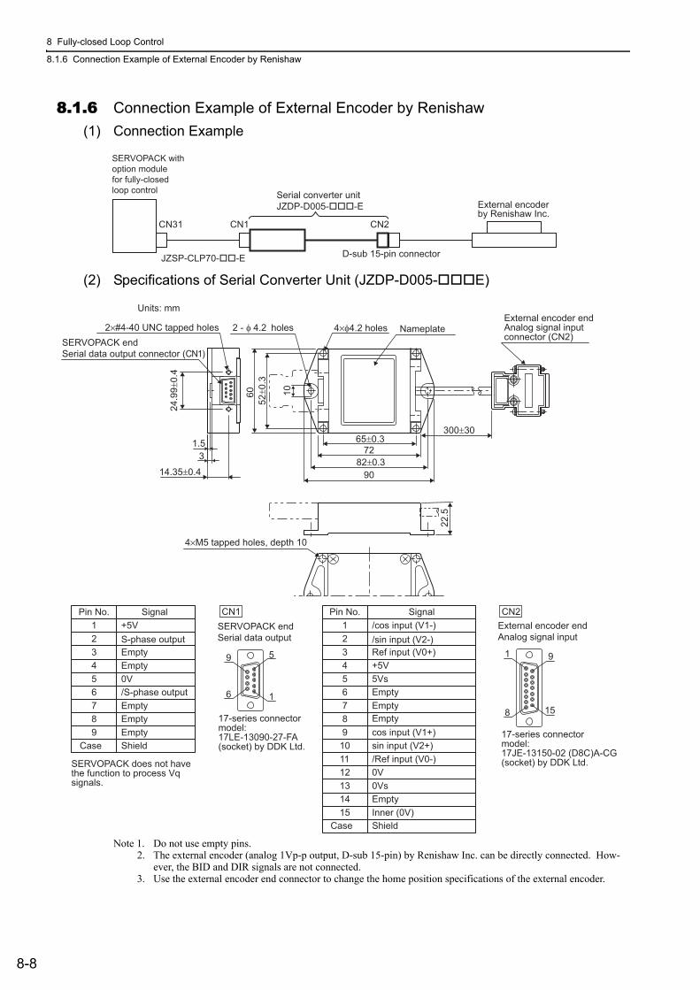
8 Fully-closed Loop Control
8.1.6 Connection Example of External Encoder by Renishaw
8-8
8.1.6 Connection Example of External Encoder by Renishaw(1) Connection Example
(2) Specifications of Serial Converter Unit (JZDP-D005- E)
Note 1. Do not use empty pins.2. The external encoder (analog 1Vp-p output, D-sub 15-pin) by Renishaw Inc. can be directly connected. How-
ever, the BID and DIR signals are not connected.3. Use the external encoder end connector to change the home position specifications of the external encoder.
Serial converter unitJZDP-D005-���-E External encoder
by Renishaw Inc.CN31 CN1 CN2
D-sub 15-pin connectorJZSP-CLP70-��-E
SERVOPACK withoption module for fully-closed loop control
82±0.3
65±0.3
72
90
1.5
3
14.35±0.4
24
.99
±0
.4
22
.5
300±30
4×M5 tapped holes, depth 10
2×#4-40 UNC tapped holes
SERVOPACK end
Serial data output connector (CN1)
Nameplate4×φ4.2 holes2 - φ 4.2 holes
Units: mm
10
52
±0
.3
60
External encoder end
Analog signal input
connector (CN2)
Pin No. Signal1 +5V
S-phase outputEmptyEmpty
Empty
0V/S-phase outputEmpty
EmptyShield
23456789
Case
Pin No. Signal1 /cos input (V1-)23 Ref input (V0+)
/sin input (V2-)
4 +5V5 5Vs6
Empty78
cos input (V1+)9sin input (V2+)10/Ref input (V0-)11
Empty
12 0V1314
Inner (0V)15
0Vs
Empty
Empty
ShieldCase
1
8
9
6 1
5 9
15
CN1 CN2
SERVOPACK does not havethe function to process Vq signals.
17-series connectormodel: 17LE-13090-27-FA(socket) by DDK Ltd.
SERVOPACK endSerial data output
External encoder endAnalog signal input
17-series connectormodel: 17JE-13150-02 (D8C)A-CG(socket) by DDK Ltd.
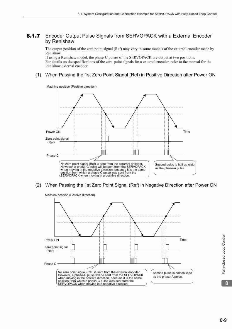
8.1 System Configuration and Connection Example for SERVOPACK with Fully-closed Loop Control
8-9
8
Fu
lly-c
lose
d L
oo
p C
on
tro
l
8.1.7 Encoder Output Pulse Signals from SERVOPACK with a External Encoder by RenishawThe output position of the zero point signal (Ref) may vary in some models of the external encoder made by Renishaw.If using a Renishaw model, the phase-C pulses of the SERVOPACK are output at two positions.For details on the specifications of the zero-point signals for a external encoder, refer to the manual for the Renishaw external encoder.
(1) When Passing the 1st Zero Point Signal (Ref) in Positive Direction after Power ON
(2) When Passing the 1st Zero Point Signal (Ref) in Negative Direction after Power ON
Machine position (Positive direction)
Power ON
Zero point signalRef
Phase-C
Time
Second pulse is half as wide as the phase-A pulse.
No zero point signal (Ref) is sent from the external encoder.However, a phase-C pulse will be sent from the SERVOPACK when moving in the negative direction, because it is the same position from which a phase-C pulse was sent from the SERVOPACK when moving in a positive direction.
Machine position (Positive direction)
Power ON
Zero point signalRef
Phase C
Time
Second pulse is half as wide as the phase-A pulse.
No zero point signal (Ref) is sent from the external encoder.However, a phase-C pulse will be sent from the SERVOPACK when moving in the positive direction, because it is the same position from which a phase-C pulse was sent from the SERVOPACK when moving in a negative direction.
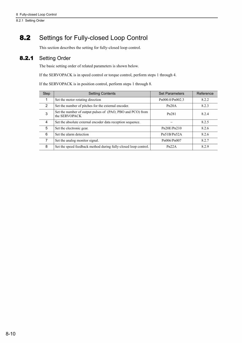
8 Fully-closed Loop Control
8.2.1 Setting Order
8-10
8.2 Settings for Fully-closed Loop ControlThis section describes the setting for fully-closed loop control.
8.2.1 Setting OrderThe basic setting order of related parameters is shown below.
If the SERVOPACK is in speed control or torque control, perform steps 1 through 4.
If the SERVOPACK is in position control, perform steps 1 through 8.
Step Setting Contents Set Parameters Reference
1 Set the motor rotating direction Pn000.0/Pn002.3 8.2.2
2 Set the number of pitches for the external encoder. Pn20A 8.2.3
3 Set the number of output pulses of (PAO, PBO and PCO) from the SERVOPACK Pn281 8.2.4
4 Set the absolute external encoder data reception sequence. − 8.2.5
5 Set the electronic gear. Pn20E/Pn210 8.2.6
6 Set the alarm detection Pn51B/Pn52A 8.2.6
7 Set the analog monitor signal. Pn006/Pn007 8.2.7
8 Set the speed feedback method during fully-closed loop control. Pn22A 8.2.9
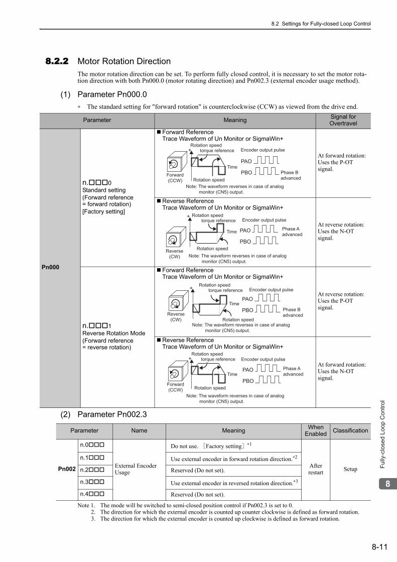
8.2 Settings for Fully-closed Loop Control
8-11
8
Fu
lly-c
lose
d L
oo
p C
on
tro
l
8.2.2 Motor Rotation DirectionThe motor rotation direction can be set. To perform fully closed control, it is necessary to set the motor rota-tion direction with both Pn000.0 (motor rotating direction) and Pn002.3 (external encoder usage method).
(1) Parameter Pn000.0∗ The standard setting for "forward rotation" is counterclockwise (CCW) as viewed from the drive end.
(2) Parameter Pn002.3
Note 1. The mode will be switched to semi-closed position control if Pn002.3 is set to 0.2. The direction for which the external encoder is counted up counter clockwise is defined as forward rotation.3. The direction for which the external encoder is counted up clockwise is defined as forward rotation.
Parameter Meaning Signal for Overtravel
Pn000
n. 0Standard setting(Forward reference= forward rotation)[Factory setting]
Forward ReferenceTrace Waveform of Un Monitor or SigmaWin+
At forward rotation:Uses the P-OTsignal.
Reverse ReferenceTrace Waveform of Un Monitor or SigmaWin+
At reverse rotation:Uses the N-OTsignal.
n. 1Reverse Rotation Mode(Forward reference= reverse rotation)
Forward ReferenceTrace Waveform of Un Monitor or SigmaWin+
At reverse rotation:Uses the P-OTsignal.
Reverse ReferenceTrace Waveform of Un Monitor or SigmaWin+
At forward rotation:Uses the N-OTsignal.
Parameter Name Meaning When Enabled Classification
Pn002
n.0
External Encoder Usage
Do not use. [Factory setting]∗1
After restart Setup
n.1 Use external encoder in forward rotation direction.∗2
n.2 Reserved (Do not set).
n.3 Use external encoder in reversed rotation direction.∗3
n.4 Reserved (Do not set).
Forward(CCW)
Phase Badvanced
Time
Encoder output pulse
PAO
PBO
Note: The waveform reverses in case of analog monitor (CN5) output.
Rotation speedtorque reference
Rotation speed
+
Reverse(CW)
Phase AadvancedTime
Encoder output pulse
Note: The waveform reverses in case of analog monitor (CN5) output.
Rotation speedtorque reference
Rotation speed
PAO
PBO
+
PAO
PBO
+
Reverse(CW)
Phase Badvanced
Time
Encoder output pulse
Note: The waveform reverses in case of analog monitor (CN5) output.
Rotation speedtorque reference
Rotation speed
Forward(CCW)
Phase Aadvanced
Encoder output pulse
Note: The waveform reverses in case of analog monitor (CN5) output.
Rotation speedtorque reference
Rotation speed
PAO
PBO
+
Time
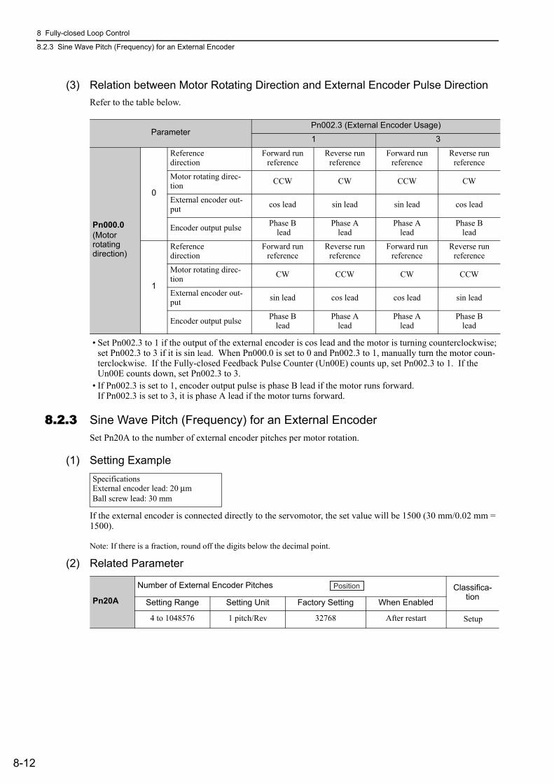
8 Fully-closed Loop Control
8.2.3 Sine Wave Pitch (Frequency) for an External Encoder
8-12
(3) Relation between Motor Rotating Direction and External Encoder Pulse DirectionRefer to the table below.
• Set Pn002.3 to 1 if the output of the external encoder is cos lead and the motor is turning counterclockwise; set Pn002.3 to 3 if it is sin lead. When Pn000.0 is set to 0 and Pn002.3 to 1, manually turn the motor coun-terclockwise. If the Fully-closed Feedback Pulse Counter (Un00E) counts up, set Pn002.3 to 1. If the Un00E counts down, set Pn002.3 to 3.
• If Pn002.3 is set to 1, encoder output pulse is phase B lead if the motor runs forward. If Pn002.3 is set to 3, it is phase A lead if the motor turns forward.
8.2.3 Sine Wave Pitch (Frequency) for an External EncoderSet Pn20A to the number of external encoder pitches per motor rotation.
(1) Setting Example
If the external encoder is connected directly to the servomotor, the set value will be 1500 (30 mm/0.02 mm = 1500).
Note: If there is a fraction, round off the digits below the decimal point.
(2) Related Parameter
ParameterPn002.3 (External Encoder Usage)
1 3
Pn000.0(Motorrotatingdirection)
0
Reference direction
Forward run reference
Reverse run reference
Forward run reference
Reverse run reference
Motor rotating direc-tion CCW CW CCW CW
External encoder out-put cos lead sin lead sin lead cos lead
Encoder output pulse Phase B lead
Phase Alead
Phase Alead
Phase Blead
1
Reference direction
Forward run reference
Reverse run reference
Forward run reference
Reverse run reference
Motor rotating direc-tion CW CCW CW CCW
External encoder out-put sin lead cos lead cos lead sin lead
Encoder output pulse Phase Blead
Phase Alead
Phase Alead
Phase Blead
SpecificationsExternal encoder lead: 20 μmBall screw lead: 30 mm
Pn20A
Number of External Encoder Pitches Classifica-tion
Setting Range Setting Unit Factory Setting When Enabled
4 to 1048576 1 pitch/Rev 32768 After restart Setup
Position
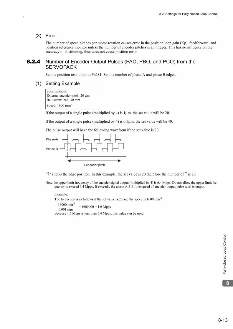
8.2 Settings for Fully-closed Loop Control
8-13
8
Fu
lly-c
lose
d L
oo
p C
on
tro
l
(3) ErrorThe number of speed pitches per motor rotation causes error in the position loop gain (Kp), feedforward, and position reference monitor unless the number of encoder pitches is an integer. This has no influence on the accuracy of positioning, thus does not cause position error.
8.2.4 Number of Encoder Output Pulses (PAO, PBO, and PCO) from the SERVOPACKSet the position resolution to Pn281. Set the number of phase A and phase B edges.
(1) Setting Example
If the output of a single pulse (multiplied by 4) is 1μm, the set value will be 20.
If the output of a single pulse (multiplied by 4) is 0.5μm, the set value will be 40.
The pulse output will have the following waveform if the set value is 20.
"↑" shows the edge position. In this example, the set value is 20 therefore the number of ↑ is 20.
Note: he upper limit frequency of the encoder signal output (multiplied by 4) is 6.4 Mpps. Do not allow the upper limit fre-quency to exceed 6.4 Mpps. If exceeds, the alarm A.511 (overspeed of encoder output pulse rate) is output.
Example:The frequency is as follows if the set value is 20 and the speed is 1600 min-1:
= 1600000 = 1.6 Mpps
Because 1.6 Mpps is less than 6.4 Mpps, this value can be used.
SpecificationsExternal encoder pitch: 20 μmBall screw lead: 30 mmSpeed: 1600 min-1
Phase-A
Phase-B
1 encoder pitch
16000 min-1
0.001 mm
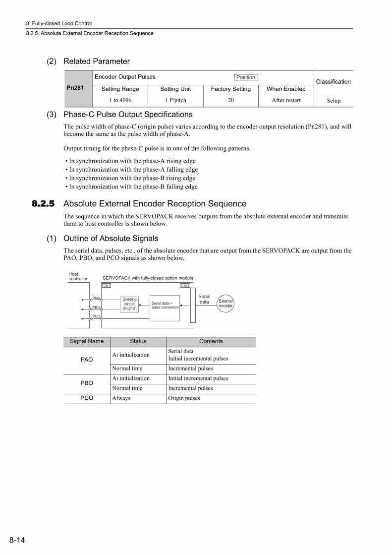
8 Fully-closed Loop Control
8.2.5 Absolute External Encoder Reception Sequence
8-14
(2) Related Parameter
(3) Phase-C Pulse Output SpecificationsThe pulse width of phase-C (origin pulse) varies according to the encoder output resolution (Pn281), and will become the same as the pulse width of phase-A.
Output timing for the phase-C pulse is in one of the following patterns.
• In synchronization with the phase-A rising edge• In synchronization with the phase-A falling edge• In synchronization with the phase-B rising edge• In synchronization with the phase-B falling edge
8.2.5 Absolute External Encoder Reception SequenceThe sequence in which the SERVOPACK receives outputs from the absolute external encoder and transmits them to host controller is shown below.
(1) Outline of Absolute SignalsThe serial data, pulses, etc., of the absolute encoder that are output from the SERVOPACK are output from the PAO, PBO, and PCO signals as shown below.
Pn281
Encoder Output PulsesClassification
Setting Range Setting Unit Factory Setting When Enabled
1 to 4096 1 P/pitch 20 After restart Setup
Position
Signal Name Status Contents
PAOAt initialization Serial data
Initial incremental pulses
Normal time Incremental pulses
PBOAt initialization Initial incremental pulses
Normal time Incremental pulses
PCO Always Origin pulses
CN31
Serialdata External
encoder
CN1
Serial data→pulse conversion
Hostcontroller SERVOPACK with fully-closed option module
PAO
PBO
PCO
Dividingcircuit
(Pn212)
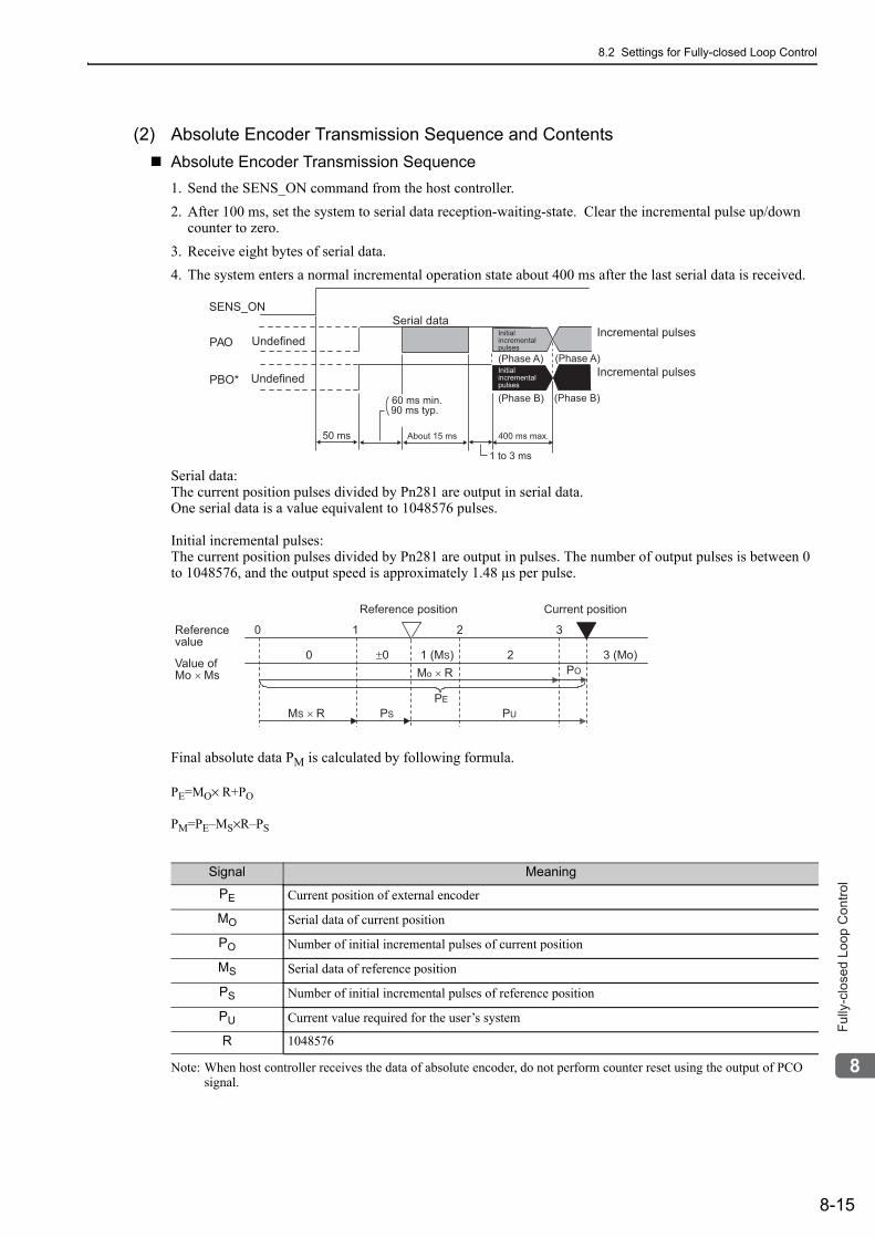
8.2 Settings for Fully-closed Loop Control
8-15
8
Fu
lly-c
lose
d L
oo
p C
on
tro
l
(2) Absolute Encoder Transmission Sequence and ContentsAbsolute Encoder Transmission Sequence1. Send the SENS_ON command from the host controller.2. After 100 ms, set the system to serial data reception-waiting-state. Clear the incremental pulse up/down
counter to zero.3. Receive eight bytes of serial data.4. The system enters a normal incremental operation state about 400 ms after the last serial data is received.
Serial data:The current position pulses divided by Pn281 are output in serial data.One serial data is a value equivalent to 1048576 pulses.
Initial incremental pulses:The current position pulses divided by Pn281 are output in pulses. The number of output pulses is between 0 to 1048576, and the output speed is approximately 1.48 µs per pulse.
Final absolute data PM is calculated by following formula.
PE=MO× R+PO
PM=PE–MS×R–PS
Note: When host controller receives the data of absolute encoder, do not perform counter reset using the output of PCO signal.
SENS_ON
PAO
PBO*
Incremental pulses
Incremental pulsesUndefined
Undefined(Phase A) (Phase A)
(Phase B) (Phase B)
Serial data
400 ms max.50 ms
1 to 3 ms
About 15 ms
90 ms typ.60 ms min.
Initialincremental pulses
Initialincremental pulses
Referencevalue
Value ofMo × Ms
Reference position
0 1 2 3
3 (Mo)
Current position
20 ±0 1 (MS)
PE
PUPSMS × R
Mo × R PO
Signal Meaning
PE Current position of external encoder
MO Serial data of current position
PO Number of initial incremental pulses of current position
MS Serial data of reference position
PS Number of initial incremental pulses of reference position
PU Current value required for the user’s system
R 1048576
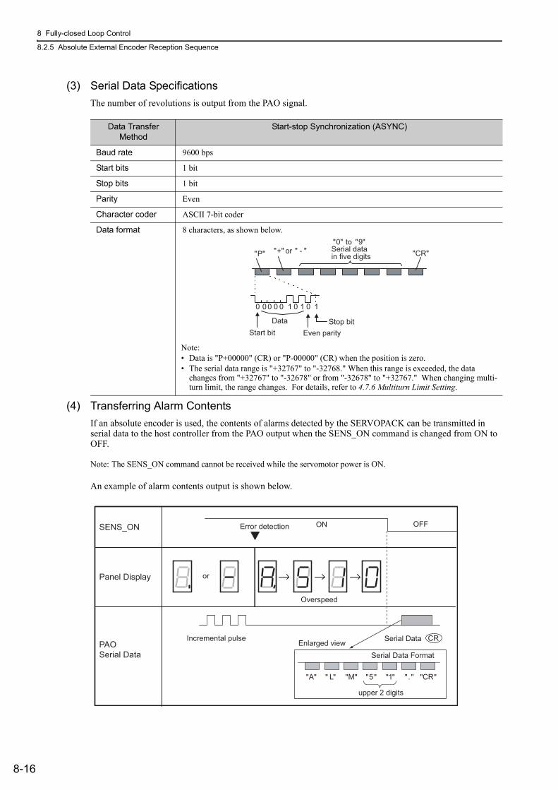
8 Fully-closed Loop Control
8.2.5 Absolute External Encoder Reception Sequence
8-16
(3) Serial Data SpecificationsThe number of revolutions is output from the PAO signal.
(4) Transferring Alarm ContentsIf an absolute encoder is used, the contents of alarms detected by the SERVOPACK can be transmitted in serial data to the host controller from the PAO output when the SENS_ON command is changed from ON to OFF.
Note: The SENS_ON command cannot be received while the servomotor power is ON.
An example of alarm contents output is shown below.
Data Transfer Method
Start-stop Synchronization (ASYNC)
Baud rate 9600 bps
Start bits 1 bit
Stop bits 1 bit
Parity Even
Character coder ASCII 7-bit coder
Data format 8 characters, as shown below.
Note:• Data is "P+00000" (CR) or "P-00000" (CR) when the position is zero.• The serial data range is "+32767" to "-32768." When this range is exceeded, the data
changes from "+32767" to "-32678" or from "-32678" to "+32767." When changing multi-turn limit, the range changes. For details, refer to 4.7.6 Multiturn Limit Setting.
DataStart bit Even parity
Serial datain five digits
"+" or " - ""0" to "9"
"CR""P"
Stop bit
0 0 0 0 0 1 0 1 0 1
OFFError detection ON
Incremental pulse CRSerial DataEnlarged view
SENS_ON
Panel Display
PAOSerial Data Serial Data Format
upper 2 digits
A L M 5 1 . CR" " " " " " " " " " " " " "
or
Overspeed
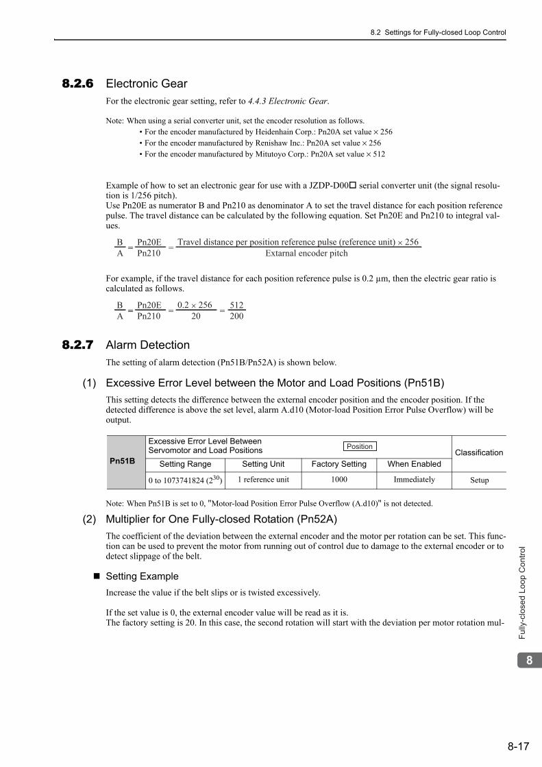
8.2 Settings for Fully-closed Loop Control
8-17
8
Fu
lly-c
lose
d L
oo
p C
on
tro
l
8.2.6 Electronic GearFor the electronic gear setting, refer to 4.4.3 Electronic Gear.
Note: When using a serial converter unit, set the encoder resolution as follows.• For the encoder manufactured by Heidenhain Corp.: Pn20A set value × 256• For the encoder manufactured by Renishaw Inc.: Pn20A set value × 256• For the encoder manufactured by Mitutoyo Corp.: Pn20A set value × 512
Example of how to set an electronic gear for use with a JZDP-D00 serial converter unit (the signal resolu-tion is 1/256 pitch). Use Pn20E as numerator B and Pn210 as denominator A to set the travel distance for each position reference pulse. The travel distance can be calculated by the following equation. Set Pn20E and Pn210 to integral val-ues.
For example, if the travel distance for each position reference pulse is 0.2 µm, then the electric gear ratio is calculated as follows.
8.2.7 Alarm DetectionThe setting of alarm detection (Pn51B/Pn52A) is shown below.
(1) Excessive Error Level between the Motor and Load Positions (Pn51B)This setting detects the difference between the external encoder position and the encoder position. If the detected difference is above the set level, alarm A.d10 (Motor-load Position Error Pulse Overflow) will be output.
Note: When Pn51B is set to 0, "Motor-load Position Error Pulse Overflow (A.d10)" is not detected.
(2) Multiplier for One Fully-closed Rotation (Pn52A)The coefficient of the deviation between the external encoder and the motor per rotation can be set. This func-tion can be used to prevent the motor from running out of control due to damage to the external encoder or to detect slippage of the belt.
Setting ExampleIncrease the value if the belt slips or is twisted excessively.
If the set value is 0, the external encoder value will be read as it is.The factory setting is 20. In this case, the second rotation will start with the deviation per motor rotation mul-
AB
Pn210Pn20E
Extarnal encoder pitchTravel distance per position reference pulse (reference unit) × 256
== =
AB
Pn210Pn20E
200.2 × 256
200512== = =
Pn51B
Excessive Error Level Between Servomotor and Load Positions Classification
Setting Range Setting Unit Factory Setting When Enabled
0 to 1073741824 (230) 1 reference unit 1000 Immediately Setup
Position
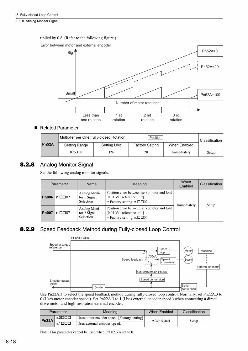
8 Fully-closed Loop Control
8.2.8 Analog Monitor Signal
8-18
tiplied by 0.8. (Refer to the following figure.)
Related Parameter
8.2.8 Analog Monitor SignalSet the following analog monitor signals.
8.2.9 Speed Feedback Method during Fully-closed Loop Control
Use Pn22A.3 to select the speed feedback method during fully-closed loop control: Normally, set Pn22A.3 to 0 (Uses motor encoder speed.). Set Pn22A.3 to 1 (Uses external encoder speed.) when connecting a direct drive motor and high-resolution external encoder.
Note: This parameter cannot be used when Pn002.3 is set to 0.
Pn52A=0
Pn52A=100
Pn52A=20
1 strotation
2 ndrotation
Number of motor rotations
Error between motor and external encoder
3 rdrotation
Less thanone rotation
Small
Big
Pn52A
Multiplier per One Fully-closed RotationClassification
Setting Range Setting Unit Factory Setting When Enabled
0 to 100 1% 20 Immediately Setup
Position
Parameter Name Meaning When Enabled Classification
Pn006 n. 07Analog Moni-tor 1 Signal Selection
Position error between servomotor and load[0.01 V/1 reference unit]∗ Factory setting: n. 02
Immediately Setup
Pn007 n. 07Analog Moni-tor 2 Signal Selection
Position error between servomotor and load[0.01 V/1 reference unit]∗ Factory setting: n. 00
Parameter Meaning When Enabled Classification
Pn22An.0 Uses motor encoder speed. [Factory setting]
After restart Setupn.1 Uses external encoder speed.
SERVOPACK
Speed or torquereference
Speed feedback
+ -
Speedconversion
Machine
External encoder
Encoder outputpulse
Motor
Encoder
Divider Serialconversion
Speedloop
Pn22A
Speed conversion
Unit conversion Pn20A
9-1
9
Tro
ub
lesh
oo
tin
g
9Troubleshooting
9.1 Troubleshooting . . . . . . . . . . . . . . . . . . . . . . . . . . . . . . . . . . . . . . . . . . . . .9-29.1.1 List of Alarms . . . . . . . . . . . . . . . . . . . . . . . . . . . . . . . . . . . . . . . . . . . . . . . . . . . . . . . . 9-29.1.2 Troubleshooting of Alarms . . . . . . . . . . . . . . . . . . . . . . . . . . . . . . . . . . . . . . . . . . . . . . 9-6
9.2 Warning Displays . . . . . . . . . . . . . . . . . . . . . . . . . . . . . . . . . . . . . . . . . . .9-219.2.1 List of Warnings . . . . . . . . . . . . . . . . . . . . . . . . . . . . . . . . . . . . . . . . . . . . . . . . . . . . . 9-219.2.2 Troubleshooting of Warnings . . . . . . . . . . . . . . . . . . . . . . . . . . . . . . . . . . . . . . . . . . . 9-22
9.3 Troubleshooting Malfunction Based on Operation and Conditions of the Servomotor . . . . . . . . . . . . . . . . . . . . . . . . . . . . . 9-25
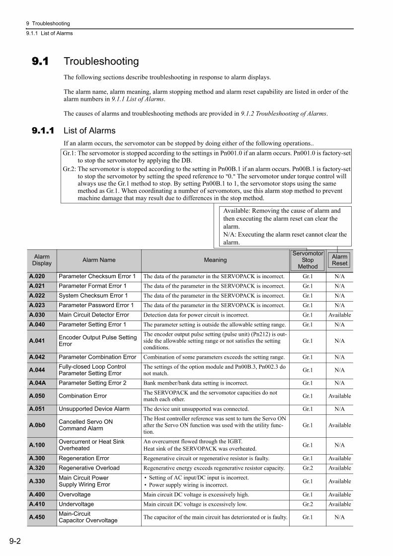
9 Troubleshooting
9.1.1 List of Alarms
9-2
9.1 TroubleshootingThe following sections describe troubleshooting in response to alarm displays.
The alarm name, alarm meaning, alarm stopping method and alarm reset capability are listed in order of the alarm numbers in 9.1.1 List of Alarms.
The causes of alarms and troubleshooting methods are provided in 9.1.2 Troubleshooting of Alarms.
9.1.1 List of AlarmsIf an alarm occurs, the servomotor can be stopped by doing either of the following operations..
Alarm Display Alarm Name Meaning
Servomotor Stop
Method
Alarm Reset
A.020 Parameter Checksum Error 1 The data of the parameter in the SERVOPACK is incorrect. Gr.1 N/AA.021 Parameter Format Error 1 The data of the parameter in the SERVOPACK is incorrect. Gr.1 N/AA.022 System Checksum Error 1 The data of the parameter in the SERVOPACK is incorrect. Gr.1 N/AA.023 Parameter Password Error 1 The data of the parameter in the SERVOPACK is incorrect. Gr.1 N/AA.030 Main Circuit Detector Error Detection data for power circuit is incorrect. Gr.1 AvailableA.040 Parameter Setting Error 1 The parameter setting is outside the allowable setting range. Gr.1 N/A
A.041 Encoder Output Pulse Setting Error
The encoder output pulse setting (pulse unit) (Pn212) is out-side the allowable setting range or not satisfies the setting conditions.
Gr.1 N/A
A.042 Parameter Combination Error Combination of some parameters exceeds the setting range. Gr.1 N/A
A.044 Fully-closed Loop Control Parameter Setting Error
The settings of the option module and Pn00B.3, Pn002.3 do not match. Gr.1 N/A
A.04A Parameter Setting Error 2 Bank member/bank data setting is incorrect. Gr.1 N/A
A.050 Combination Error The SERVOPACK and the servomotor capacities do not match each other. Gr.1 Available
A.051 Unsupported Device Alarm The device unit unsupported was connected. Gr.1 N/A
A.0b0 Cancelled Servo ON Command Alarm
The Host controller reference was sent to turn the Servo ON after the Servo ON function was used with the utility func-tion.
Gr.1 Available
A.100 Overcurrent or Heat Sink Overheated
An overcurrent flowed through the IGBT.Heat sink of the SERVOPACK was overheated. Gr.1 N/A
A.300 Regeneration Error Regenerative circuit or regenerative resistor is faulty. Gr.1 AvailableA.320 Regenerative Overload Regenerative energy exceeds regenerative resistor capacity. Gr.2 Available
A.330 Main Circuit Power Supply Wiring Error
• Setting of AC input/DC input is incorrect.• Power supply wiring is incorrect. Gr.1 Available
A.400 Overvoltage Main circuit DC voltage is excessively high. Gr.1 AvailableA.410 Undervoltage Main circuit DC voltage is excessively low. Gr.2 Available
A.450 Main-Circuit Capacitor Overvoltage The capacitor of the main circuit has deteriorated or is faulty. Gr.1 N/A
Gr.1: The servomotor is stopped according to the settings in Pn001.0 if an alarm occurs. Pn001.0 is factory-set to stop the servomotor by applying the DB.
Gr.2: The servomotor is stopped according to the setting in Pn00B.1 if an alarm occurs. Pn00B.1 is factory-set to stop the servomotor by setting the speed reference to "0." The servomotor under torque control will always use the Gr.1 method to stop. By setting Pn00B.1 to 1, the servomotor stops using the same method as Gr.1. When coordinating a number of servomotors, use this alarm stop method to prevent machine damage that may result due to differences in the stop method.
Available: Removing the cause of alarm and then executing the alarm reset can clear the alarm. N/A: Executing the alarm reset cannot clear the alarm.

9.1 Troubleshooting
9-3
9
Tro
ub
lesh
oo
tin
g
Alarm Display Alarm Name Meaning
Servomotor Stop
Method
Alarm Reset
A.510 Overspeed The servomotor speed is excessively high. Gr.1 Available
A.511 Overspeed of Encoder Output Pulse Rate
The motor speed upper limit of the set encoder output pulse (pulse unit) (Pn212) is exceeded. Gr.1 Available
A.520 Vibration Alarm Vibration at the motor speed was detected. Gr.1 Available
A.521 Autotuning Alarm Vibration was detected while performing tuning-less func-tion. Gr.1 Available
A.710 Overload: High Load The motor was operating for several seconds to several tens of seconds under a torque largely exceeding ratings. Gr.2 Available
A.720 Overload: Low Load The motor was operating continuously under a torque largely exceeding ratings. Gr.1 Available
A.730A.731 Dynamic Brake Overload When the dynamic brake was applied, rotational energy
exceeded the capacity of dynamic brake resistor. Gr.1 Available
A.740 Overload of Surge Current Limit Resistor The main circuit power was frequently turned ON and OFF. Gr.1 Available
A.7A0 Heat Sink Overheated The heat sink of the SERVOPACK exceeded 100°C. Gr.2 Available
A.7AB Built-in Fan in SERVOPACK Stopped The fan inside the SERVOPACK stopped. Gr.1 Available
A.810 Encoder Backup Error All the power supplies for the absolute encoder have failed and position data was cleared. Gr.1 N/A
A.820 Encoder Checksum Error The checksum results of encoder memory is incorrect. Gr.1 N/A
A.830 Absolute Encoder Battery ErrorThe battery voltage was lower than the specified value while monitoring 4 seconds after the ALM signal outputs max. 5 seconds when the control power supply is turned ON.
Gr.1 Available
A.840 Encoder Data Error Data in the encoder is incorrect. Gr.1 N/A
A.850 Encoder Overspeed The encoder was rotating at high speed when the power was turned ON. Gr.1 N/A
A.860 Encoder Overheated The internal temperature of encoder is too high. Gr.1 N/A
A.8A0 External Encoder Error of Scale External encoder is faulty. Gr.1 Available
A.8A1 External Encoder Error of Module Serial converter unit is faulty. Gr.1 Available
A.8A2 External Encoder Error of Sensor (Incremental) External encoder is faulty. Gr.1 Available
A.8A3 External Encoder Error of Position (Absolute) The position of external encoder is faulty. Gr.1 Available
A.8A5 External Encoder Overspeed The overspeed from the external encoder occurred. Gr.1 Available
A.8A6 External Encoder Overheated The overheat from the external encoder occurred. Gr.1 Available
A.b31 Current Detection Error1 (Phase-U) The current detection circuit for phase-U is faulty. Gr.1 N/A
A.b32 Current Detection Error 2 (Phase-V) The current detection circuit for phase-V is faulty. Gr.1 N/A
A.b33 Current Detection Error 3 (Current detector) The detection circuit for the current is faulty. Gr.1 N/A
A.b6AMECHATROLINKCommunicationsASIC Error 1
ASIC error occurred in the MECHATROLINK communica-tions. Gr.1 N/A
A.bF0 System Alarm 0 "Internal program error 0" occurred in the SERVOPACK. Gr.1 N/A
A.bF1 System Alarm 1 "Internal program error 1" occurred in the SERVOPACK. Gr.1 N/A
A.bF2 System Alarm 2 "Internal program error 2" occurred in the SERVOPACK. Gr.1 N/A
A.bF3 System Alarm 3 "Internal program error 3" occurred in the SERVOPACK. Gr.1 N/A
A.bF4 System Alarm 4 "Internal program error 4" occurred in the SERVOPACK. Gr.1 N/A
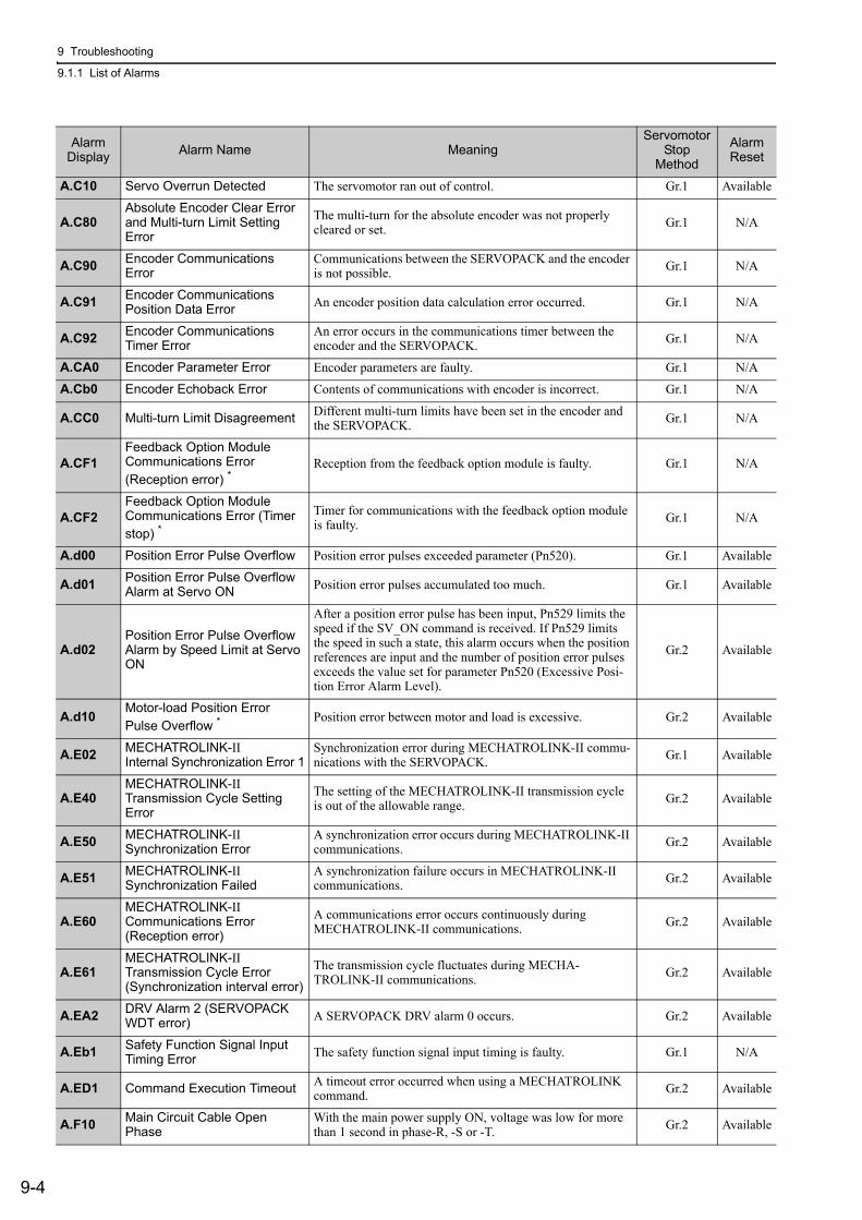
9 Troubleshooting
9.1.1 List of Alarms
9-4
A.C10 Servo Overrun Detected The servomotor ran out of control. Gr.1 Available
A.C80Absolute Encoder Clear Error and Multi-turn Limit Setting Error
The multi-turn for the absolute encoder was not properly cleared or set. Gr.1 N/A
A.C90 Encoder Communications Error
Communications between the SERVOPACK and the encoder is not possible. Gr.1 N/A
A.C91 Encoder Communications Position Data Error An encoder position data calculation error occurred. Gr.1 N/A
A.C92 Encoder Communications Timer Error
An error occurs in the communications timer between the encoder and the SERVOPACK. Gr.1 N/A
A.CA0 Encoder Parameter Error Encoder parameters are faulty. Gr.1 N/A
A.Cb0 Encoder Echoback Error Contents of communications with encoder is incorrect. Gr.1 N/A
A.CC0 Multi-turn Limit Disagreement Different multi-turn limits have been set in the encoder and the SERVOPACK. Gr.1 N/A
A.CF1Feedback Option Module Communications Error (Reception error) *
Reception from the feedback option module is faulty. Gr.1 N/A
A.CF2Feedback Option Module Communications Error (Timer stop) *
Timer for communications with the feedback option module is faulty. Gr.1 N/A
A.d00 Position Error Pulse Overflow Position error pulses exceeded parameter (Pn520). Gr.1 Available
A.d01 Position Error Pulse Overflow Alarm at Servo ON Position error pulses accumulated too much. Gr.1 Available
A.d02Position Error Pulse Overflow Alarm by Speed Limit at Servo ON
After a position error pulse has been input, Pn529 limits the speed if the SV_ON command is received. If Pn529 limits the speed in such a state, this alarm occurs when the position references are input and the number of position error pulses exceeds the value set for parameter Pn520 (Excessive Posi-tion Error Alarm Level).
Gr.2 Available
A.d10 Motor-load Position Error Pulse Overflow *
Position error between motor and load is excessive. Gr.2 Available
A.E02 MECHATROLINK-II Internal Synchronization Error 1
Synchronization error during MECHATROLINK-II commu-nications with the SERVOPACK. Gr.1 Available
A.E40MECHATROLINK-II Transmission Cycle Setting Error
The setting of the MECHATROLINK-II transmission cycle is out of the allowable range. Gr.2 Available
A.E50 MECHATROLINK-II Synchronization Error
A synchronization error occurs during MECHATROLINK-II communications. Gr.2 Available
A.E51 MECHATROLINK-II Synchronization Failed
A synchronization failure occurs in MECHATROLINK-II communications. Gr.2 Available
A.E60MECHATROLINK-II Communications Error (Reception error)
A communications error occurs continuously during MECHATROLINK-II communications. Gr.2 Available
A.E61MECHATROLINK-II Transmission Cycle Error (Synchronization interval error)
The transmission cycle fluctuates during MECHA-TROLINK-II communications. Gr.2 Available
A.EA2 DRV Alarm 2 (SERVOPACK WDT error) A SERVOPACK DRV alarm 0 occurs. Gr.2 Available
A.Eb1 Safety Function Signal Input Timing Error The safety function signal input timing is faulty. Gr.1 N/A
A.ED1 Command Execution Timeout A timeout error occurred when using a MECHATROLINK command. Gr.2 Available
A.F10 Main Circuit Cable Open Phase
With the main power supply ON, voltage was low for more than 1 second in phase-R, -S or -T. Gr.2 Available
Alarm Display Alarm Name Meaning
Servomotor Stop
Method
Alarm Reset
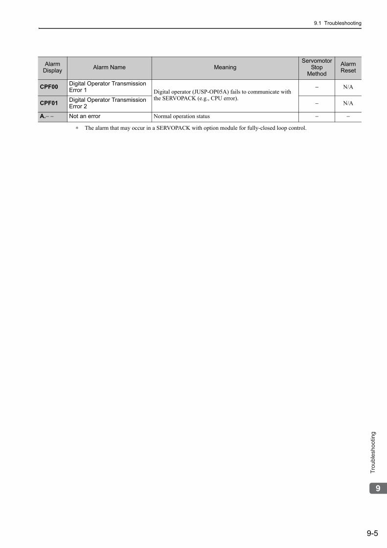
9.1 Troubleshooting
9-5
9
Tro
ub
lesh
oo
tin
g
∗ The alarm that may occur in a SERVOPACK with option module for fully-closed loop control.
CPF00 Digital Operator Transmission Error 1 Digital operator (JUSP-OP05A) fails to communicate with
the SERVOPACK (e.g., CPU error).
− N/A
CPF01 Digital Operator Transmission Error 2 − N/A
A.− − Not an error Normal operation status − −
Alarm Display Alarm Name Meaning
Servomotor Stop
Method
Alarm Reset
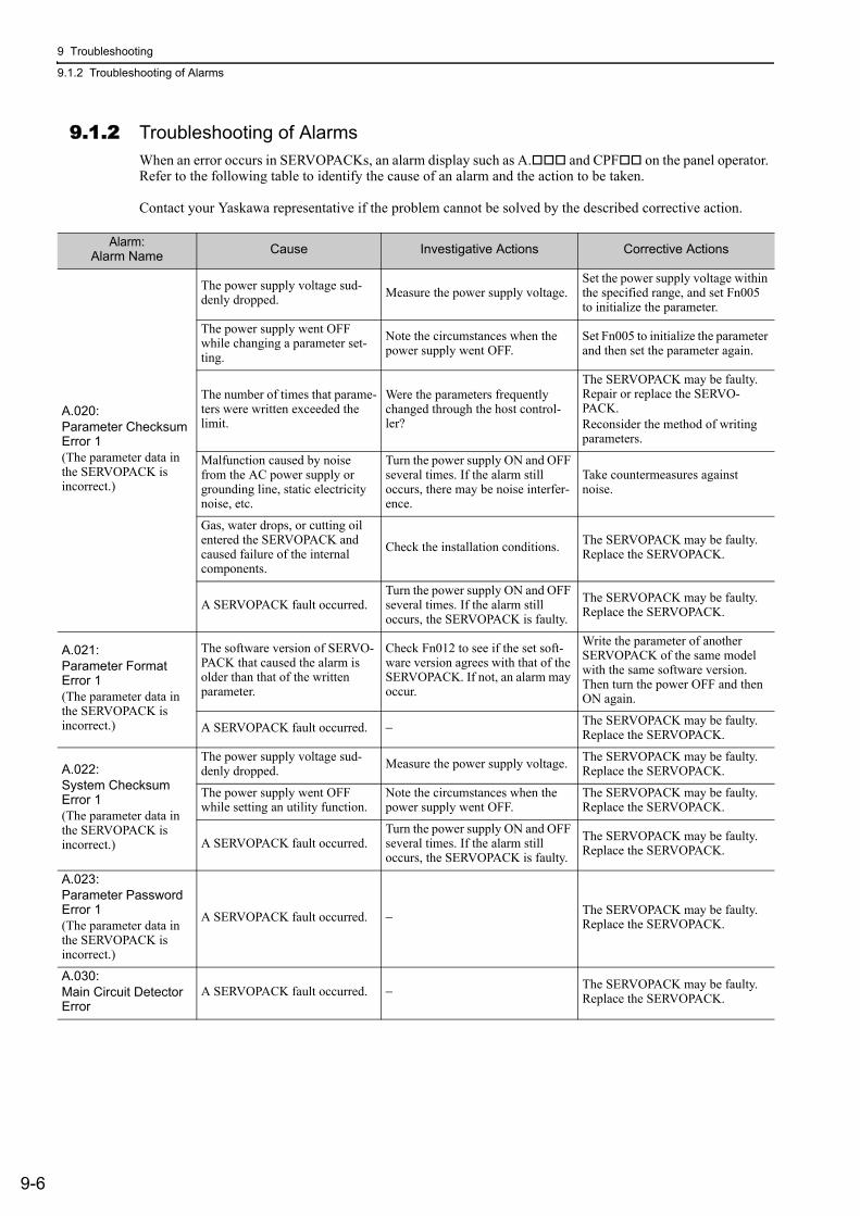
9 Troubleshooting
9.1.2 Troubleshooting of Alarms
9-6
9.1.2 Troubleshooting of AlarmsWhen an error occurs in SERVOPACKs, an alarm display such as A. and CPF on the panel operator. Refer to the following table to identify the cause of an alarm and the action to be taken.
Contact your Yaskawa representative if the problem cannot be solved by the described corrective action.
Alarm:Alarm Name Cause Investigative Actions Corrective Actions
A.020:Parameter Checksum Error 1(The parameter data in the SERVOPACK is incorrect.)
The power supply voltage sud-denly dropped. Measure the power supply voltage.
Set the power supply voltage within the specified range, and set Fn005 to initialize the parameter.
The power supply went OFF while changing a parameter set-ting.
Note the circumstances when the power supply went OFF.
Set Fn005 to initialize the parameter and then set the parameter again.
The number of times that parame-ters were written exceeded the limit.
Were the parameters frequently changed through the host control-ler?
The SERVOPACK may be faulty. Repair or replace the SERVO-PACK.Reconsider the method of writing parameters.
Malfunction caused by noise from the AC power supply or grounding line, static electricity noise, etc.
Turn the power supply ON and OFF several times. If the alarm still occurs, there may be noise interfer-ence.
Take countermeasures against noise.
Gas, water drops, or cutting oil entered the SERVOPACK and caused failure of the internal components.
Check the installation conditions. The SERVOPACK may be faulty. Replace the SERVOPACK.
A SERVOPACK fault occurred.Turn the power supply ON and OFF several times. If the alarm still occurs, the SERVOPACK is faulty.
The SERVOPACK may be faulty. Replace the SERVOPACK.
A.021:Parameter Format Error 1(The parameter data in the SERVOPACK is incorrect.)
The software version of SERVO-PACK that caused the alarm is older than that of the written parameter.
Check Fn012 to see if the set soft-ware version agrees with that of the SERVOPACK. If not, an alarm may occur.
Write the parameter of another SERVOPACK of the same model with the same software version. Then turn the power OFF and then ON again.
A SERVOPACK fault occurred. − The SERVOPACK may be faulty. Replace the SERVOPACK.
A.022:System Checksum Error 1(The parameter data in the SERVOPACK is incorrect.)
The power supply voltage sud-denly dropped. Measure the power supply voltage. The SERVOPACK may be faulty.
Replace the SERVOPACK.
The power supply went OFF while setting an utility function.
Note the circumstances when the power supply went OFF.
The SERVOPACK may be faulty. Replace the SERVOPACK.
A SERVOPACK fault occurred.Turn the power supply ON and OFF several times. If the alarm still occurs, the SERVOPACK is faulty.
The SERVOPACK may be faulty. Replace the SERVOPACK.
A.023:Parameter Password Error 1(The parameter data in the SERVOPACK is incorrect.)
A SERVOPACK fault occurred. − The SERVOPACK may be faulty. Replace the SERVOPACK.
A.030:Main Circuit Detector Error
A SERVOPACK fault occurred. − The SERVOPACK may be faulty. Replace the SERVOPACK.
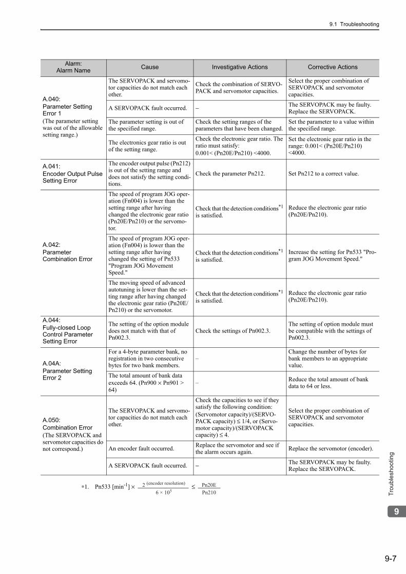
9.1 Troubleshooting
9-7
9
Tro
ub
lesh
oo
tin
g
A.040:Parameter Setting Error 1(The parameter setting was out of the allowable setting range.)
The SERVOPACK and servomo-tor capacities do not match each other.
Check the combination of SERVO-PACK and servomotor capacities.
Select the proper combination of SERVOPACK and servomotor capacities.
A SERVOPACK fault occurred. − The SERVOPACK may be faulty. Replace the SERVOPACK.
The parameter setting is out of the specified range.
Check the setting ranges of the parameters that have been changed.
Set the parameter to a value within the specified range.
The electronics gear ratio is out of the setting range.
Check the electronic gear ratio. The ratio must satisfy:0.001< (Pn20E/Pn210) <4000.
Set the electronic gear ratio in the range: 0.001< (Pn20E/Pn210) <4000.
A.041:Encoder Output Pulse Setting Error
The encoder output pulse (Pn212) is out of the setting range and does not satisfy the setting condi-tions.
Check the parameter Pn212. Set Pn212 to a correct value.
A.042:Parameter Combination Error
The speed of program JOG oper-ation (Fn004) is lower than the setting range after having changed the electronic gear ratio (Pn20E/Pn210) or the servomo-tor.
Check that the detection conditions*1
is satisfied.Reduce the electronic gear ratio (Pn20E/Pn210).
The speed of program JOG oper-ation (Fn004) is lower than the setting range after having changed the setting of Pn533 "Program JOG Movement Speed."
Check that the detection conditions*1 is satisfied.
Increase the setting for Pn533 "Pro-gram JOG Movement Speed."
The moving speed of advanced autotuning is lower than the set-ting range after having changed the electronic gear ratio (Pn20E/Pn210) or the servomotor.
Check that the detection conditions*1 is satisfied.
Reduce the electronic gear ratio (Pn20E/Pn210).
A.044:Fully-closed Loop Control Parameter Setting Error
The setting of the option module does not match with that of Pn002.3.
Check the settings of Pn002.3.The setting of option module must be compatible with the settings of Pn002.3.
A.04A:Parameter Setting Error 2
For a 4-byte parameter bank, no registration in two consecutive bytes for two bank members.
–Change the number of bytes for bank members to an appropriate value.
The total amount of bank data exceeds 64. (Pn900 × Pn901 > 64)
– Reduce the total amount of bank data to 64 or less.
A.050:Combination Error(The SERVOPACK and servomotor capacities do not correspond.)
The SERVOPACK and servomo-tor capacities do not match each other.
Check the capacities to see if they satisfy the following condition:(Servomotor capacity)/(SERVO-PACK capacity) ≤ 1/4, or (Servo-motor capacity)/(SERVOPACK capacity) ≤ 4.
Select the proper combination of SERVOPACK and servomotor capacities.
An encoder fault occurred. Replace the servomotor and see if the alarm occurs again. Replace the servomotor (encoder).
A SERVOPACK fault occurred. − The SERVOPACK may be faulty. Replace the SERVOPACK.
∗1. Pn533 [min-1] × ≤
Alarm:Alarm Name Cause Investigative Actions Corrective Actions
2 (encoder resolution)
6 × 10⁵Pn20EPn210
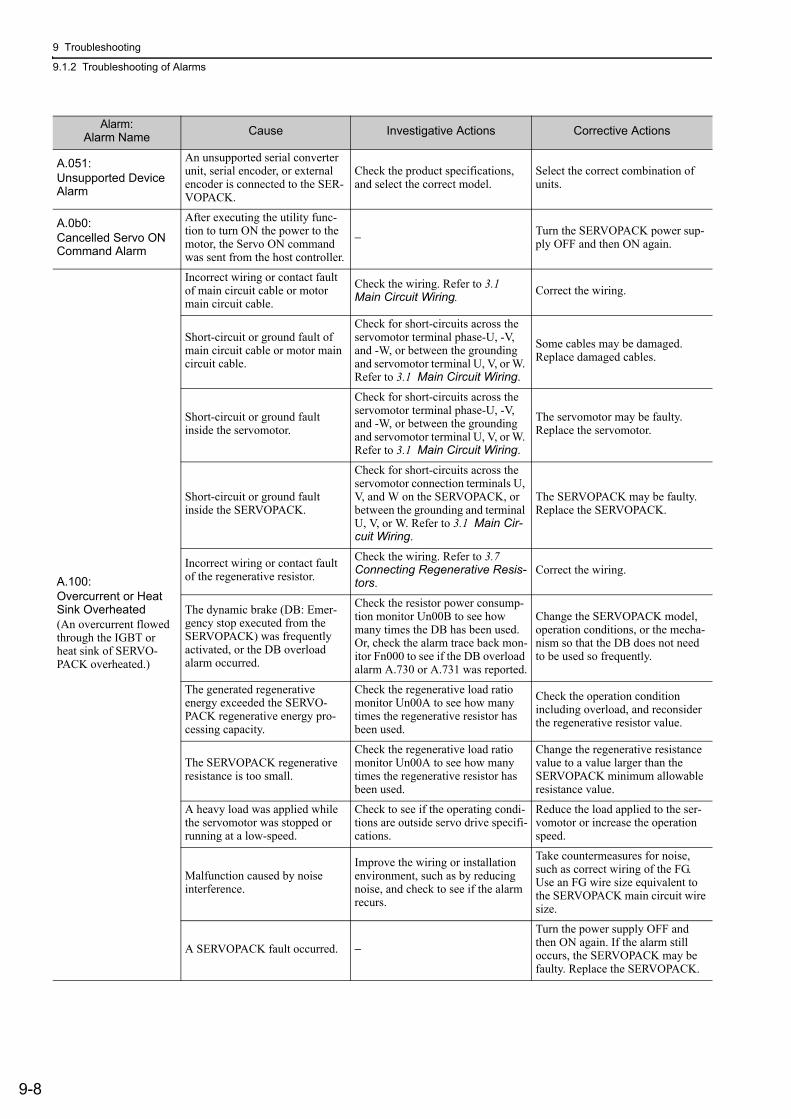
9 Troubleshooting
9.1.2 Troubleshooting of Alarms
9-8
A.051:Unsupported Device Alarm
An unsupported serial converter unit, serial encoder, or external encoder is connected to the SER-VOPACK.
Check the product specifications, and select the correct model.
Select the correct combination of units.
A.0b0:Cancelled Servo ON Command Alarm
After executing the utility func-tion to turn ON the power to the motor, the Servo ON command was sent from the host controller.
− Turn the SERVOPACK power sup-ply OFF and then ON again.
A.100:Overcurrent or Heat Sink Overheated(An overcurrent flowed through the IGBT or heat sink of SERVO-PACK overheated.)
Incorrect wiring or contact fault of main circuit cable or motor main circuit cable.
Check the wiring. Refer to 3.1 Main Circuit Wiring. Correct the wiring.
Short-circuit or ground fault of main circuit cable or motor main circuit cable.
Check for short-circuits across the servomotor terminal phase-U, -V, and -W, or between the grounding and servomotor terminal U, V, or W. Refer to 3.1 Main Circuit Wiring.
Some cables may be damaged. Replace damaged cables.
Short-circuit or ground fault inside the servomotor.
Check for short-circuits across the servomotor terminal phase-U, -V, and -W, or between the grounding and servomotor terminal U, V, or W. Refer to 3.1 Main Circuit Wiring.
The servomotor may be faulty. Replace the servomotor.
Short-circuit or ground fault inside the SERVOPACK.
Check for short-circuits across the servomotor connection terminals U, V, and W on the SERVOPACK, or between the grounding and terminal U, V, or W. Refer to 3.1 Main Cir-cuit Wiring.
The SERVOPACK may be faulty. Replace the SERVOPACK.
Incorrect wiring or contact fault of the regenerative resistor.
Check the wiring. Refer to 3.7 Connecting Regenerative Resis-tors.
Correct the wiring.
The dynamic brake (DB: Emer-gency stop executed from the SERVOPACK) was frequently activated, or the DB overload alarm occurred.
Check the resistor power consump-tion monitor Un00B to see how many times the DB has been used. Or, check the alarm trace back mon-itor Fn000 to see if the DB overload alarm A.730 or A.731 was reported.
Change the SERVOPACK model, operation conditions, or the mecha-nism so that the DB does not need to be used so frequently.
The generated regenerative energy exceeded the SERVO-PACK regenerative energy pro-cessing capacity.
Check the regenerative load ratio monitor Un00A to see how many times the regenerative resistor has been used.
Check the operation condition including overload, and reconsider the regenerative resistor value.
The SERVOPACK regenerative resistance is too small.
Check the regenerative load ratio monitor Un00A to see how many times the regenerative resistor has been used.
Change the regenerative resistance value to a value larger than the SERVOPACK minimum allowable resistance value.
A heavy load was applied while the servomotor was stopped or running at a low-speed.
Check to see if the operating condi-tions are outside servo drive specifi-cations.
Reduce the load applied to the ser-vomotor or increase the operation speed.
Malfunction caused by noise interference.
Improve the wiring or installation environment, such as by reducing noise, and check to see if the alarm recurs.
Take countermeasures for noise, such as correct wiring of the FG. Use an FG wire size equivalent to the SERVOPACK main circuit wire size.
A SERVOPACK fault occurred. −
Turn the power supply OFF and then ON again. If the alarm still occurs, the SERVOPACK may be faulty. Replace the SERVOPACK.
Alarm:Alarm Name Cause Investigative Actions Corrective Actions
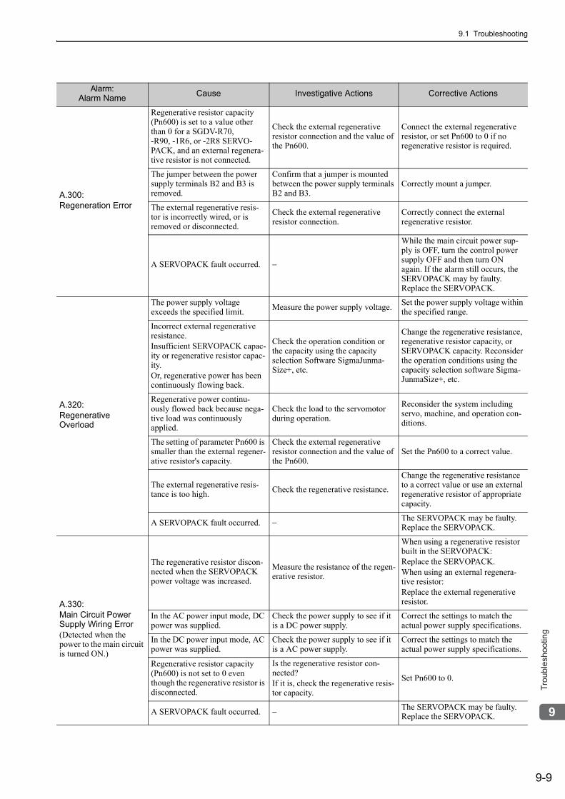
9.1 Troubleshooting
9-9
9
Tro
ub
lesh
oo
tin
g
A.300:Regeneration Error
Regenerative resistor capacity (Pn600) is set to a value other than 0 for a SGDV-R70, -R90, -1R6, or -2R8 SERVO-PACK, and an external regenera-tive resistor is not connected.
Check the external regenerative resistor connection and the value of the Pn600.
Connect the external regenerative resistor, or set Pn600 to 0 if no regenerative resistor is required.
The jumper between the power supply terminals B2 and B3 is removed.
Confirm that a jumper is mounted between the power supply terminals B2 and B3.
Correctly mount a jumper.
The external regenerative resis-tor is incorrectly wired, or is removed or disconnected.
Check the external regenerative resistor connection.
Correctly connect the external regenerative resistor.
A SERVOPACK fault occurred. −
While the main circuit power sup-ply is OFF, turn the control power supply OFF and then turn ON again. If the alarm still occurs, the SERVOPACK may by faulty. Replace the SERVOPACK.
A.320:Regenerative Overload
The power supply voltage exceeds the specified limit. Measure the power supply voltage. Set the power supply voltage within
the specified range.
Incorrect external regenerative resistance.Insufficient SERVOPACK capac-ity or regenerative resistor capac-ity. Or, regenerative power has been continuously flowing back.
Check the operation condition or the capacity using the capacity selection Software SigmaJunma-Size+, etc.
Change the regenerative resistance, regenerative resistor capacity, or SERVOPACK capacity. Reconsider the operation conditions using the capacity selection software Sigma-JunmaSize+, etc.
Regenerative power continu-ously flowed back because nega-tive load was continuously applied.
Check the load to the servomotor during operation.
Reconsider the system including servo, machine, and operation con-ditions.
The setting of parameter Pn600 is smaller than the external regener-ative resistor's capacity.
Check the external regenerative resistor connection and the value of the Pn600.
Set the Pn600 to a correct value.
The external regenerative resis-tance is too high. Check the regenerative resistance.
Change the regenerative resistance to a correct value or use an external regenerative resistor of appropriate capacity.
A SERVOPACK fault occurred. − The SERVOPACK may be faulty. Replace the SERVOPACK.
A.330:Main Circuit Power Supply Wiring Error(Detected when the power to the main circuit is turned ON.)
The regenerative resistor discon-nected when the SERVOPACK power voltage was increased.
Measure the resistance of the regen-erative resistor.
When using a regenerative resistor built in the SERVOPACK:Replace the SERVOPACK.When using an external regenera-tive resistor:Replace the external regenerative resistor.
In the AC power input mode, DC power was supplied.
Check the power supply to see if it is a DC power supply.
Correct the settings to match the actual power supply specifications.
In the DC power input mode, AC power was supplied.
Check the power supply to see if it is a AC power supply.
Correct the settings to match the actual power supply specifications.
Regenerative resistor capacity (Pn600) is not set to 0 even though the regenerative resistor is disconnected.
Is the regenerative resistor con-nected?If it is, check the regenerative resis-tor capacity.
Set Pn600 to 0.
A SERVOPACK fault occurred. − The SERVOPACK may be faulty. Replace the SERVOPACK.
Alarm:Alarm Name Cause Investigative Actions Corrective Actions
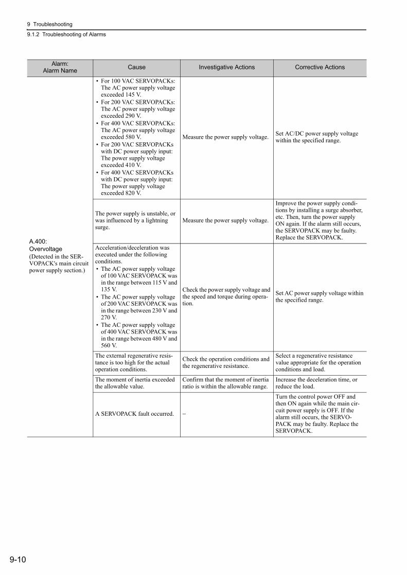
9 Troubleshooting
9.1.2 Troubleshooting of Alarms
9-10
A.400:Overvoltage(Detected in the SER-VOPACK's main circuit power supply section.)
• For 100 VAC SERVOPACKs: The AC power supply voltage exceeded 145 V.
• For 200 VAC SERVOPACKs:The AC power supply voltage exceeded 290 V.
• For 400 VAC SERVOPACKs:The AC power supply voltage exceeded 580 V.
• For 200 VAC SERVOPACKs with DC power supply input: The power supply voltage exceeded 410 V.
• For 400 VAC SERVOPACKs with DC power supply input: The power supply voltage exceeded 820 V.
Measure the power supply voltage. Set AC/DC power supply voltage within the specified range.
The power supply is unstable, or was influenced by a lightning surge.
Measure the power supply voltage.
Improve the power supply condi-tions by installing a surge absorber, etc. Then, turn the power supply ON again. If the alarm still occurs, the SERVOPACK may be faulty. Replace the SERVOPACK.
Acceleration/deceleration was executed under the following conditions.• The AC power supply voltage
of 100 VAC SERVOPACK was in the range between 115 V and 135 V.
• The AC power supply voltage of 200 VAC SERVOPACK was in the range between 230 V and 270 V.
• The AC power supply voltage of 400 VAC SERVOPACK was in the range between 480 V and 560 V.
Check the power supply voltage and the speed and torque during opera-tion.
Set AC power supply voltage within the specified range.
The external regenerative resis-tance is too high for the actual operation conditions.
Check the operation conditions and the regenerative resistance.
Select a regenerative resistance value appropriate for the operation conditions and load.
The moment of inertia exceeded the allowable value.
Confirm that the moment of inertia ratio is within the allowable range.
Increase the deceleration time, or reduce the load.
A SERVOPACK fault occurred. −
Turn the control power OFF and then ON again while the main cir-cuit power supply is OFF. If the alarm still occurs, the SERVO-PACK may be faulty. Replace the SERVOPACK.
Alarm:Alarm Name Cause Investigative Actions Corrective Actions
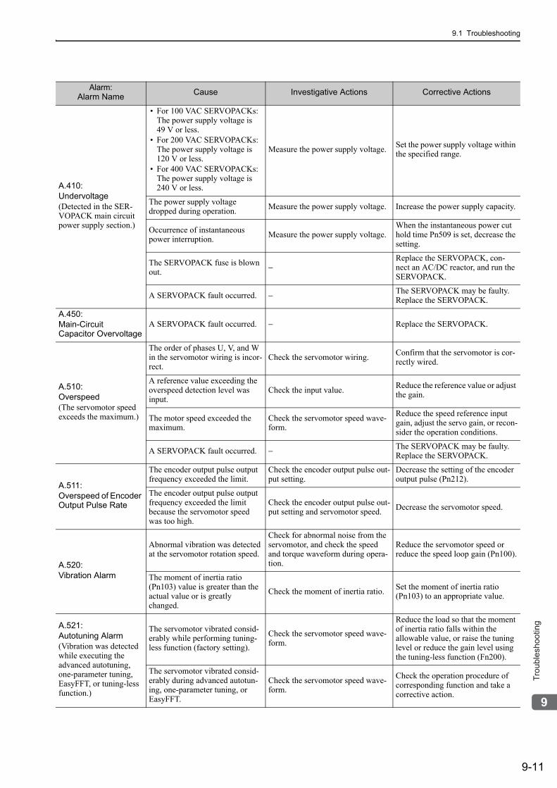
9.1 Troubleshooting
9-11
9
Tro
ub
lesh
oo
tin
g
A.410:Undervoltage(Detected in the SER-VOPACK main circuit power supply section.)
• For 100 VAC SERVOPACKs: The power supply voltage is 49 V or less.
• For 200 VAC SERVOPACKs: The power supply voltage is 120 V or less.
• For 400 VAC SERVOPACKs: The power supply voltage is 240 V or less.
Measure the power supply voltage. Set the power supply voltage within the specified range.
The power supply voltage dropped during operation. Measure the power supply voltage. Increase the power supply capacity.
Occurrence of instantaneous power interruption. Measure the power supply voltage.
When the instantaneous power cut hold time Pn509 is set, decrease the setting.
The SERVOPACK fuse is blown out. −
Replace the SERVOPACK, con-nect an AC/DC reactor, and run the SERVOPACK.
A SERVOPACK fault occurred. − The SERVOPACK may be faulty. Replace the SERVOPACK.
A.450:Main-Circuit Capacitor Overvoltage
A SERVOPACK fault occurred. − Replace the SERVOPACK.
A.510:Overspeed(The servomotor speed exceeds the maximum.)
The order of phases U, V, and W in the servomotor wiring is incor-rect.
Check the servomotor wiring. Confirm that the servomotor is cor-rectly wired.
A reference value exceeding the overspeed detection level was input.
Check the input value. Reduce the reference value or adjust the gain.
The motor speed exceeded the maximum.
Check the servomotor speed wave-form.
Reduce the speed reference input gain, adjust the servo gain, or recon-sider the operation conditions.
A SERVOPACK fault occurred. − The SERVOPACK may be faulty. Replace the SERVOPACK.
A.511:Overspeed of Encoder Output Pulse Rate
The encoder output pulse output frequency exceeded the limit.
Check the encoder output pulse out-put setting.
Decrease the setting of the encoder output pulse (Pn212).
The encoder output pulse output frequency exceeded the limit because the servomotor speed was too high.
Check the encoder output pulse out-put setting and servomotor speed. Decrease the servomotor speed.
A.520:Vibration Alarm
Abnormal vibration was detected at the servomotor rotation speed.
Check for abnormal noise from the servomotor, and check the speed and torque waveform during opera-tion.
Reduce the servomotor speed or reduce the speed loop gain (Pn100).
The moment of inertia ratio (Pn103) value is greater than the actual value or is greatly changed.
Check the moment of inertia ratio. Set the moment of inertia ratio (Pn103) to an appropriate value.
A.521:Autotuning Alarm(Vibration was detected while executing the advanced autotuning, one-parameter tuning, EasyFFT, or tuning-less function.)
The servomotor vibrated consid-erably while performing tuning-less function (factory setting).
Check the servomotor speed wave-form.
Reduce the load so that the moment of inertia ratio falls within the allowable value, or raise the tuning level or reduce the gain level using the tuning-less function (Fn200).
The servomotor vibrated consid-erably during advanced autotun-ing, one-parameter tuning, or EasyFFT.
Check the servomotor speed wave-form.
Check the operation procedure of corresponding function and take a corrective action.
Alarm:Alarm Name Cause Investigative Actions Corrective Actions
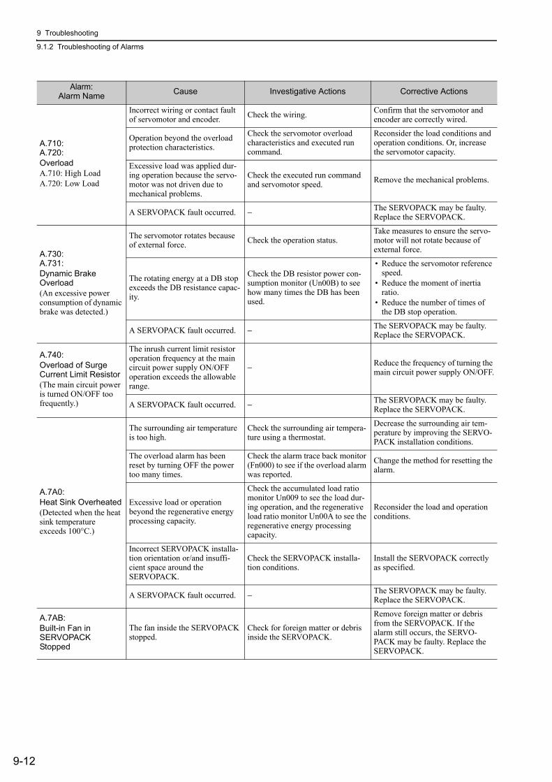
9 Troubleshooting
9.1.2 Troubleshooting of Alarms
9-12
A.710:A.720:Overload A.710: High LoadA.720: Low Load
Incorrect wiring or contact fault of servomotor and encoder. Check the wiring. Confirm that the servomotor and
encoder are correctly wired.
Operation beyond the overload protection characteristics.
Check the servomotor overload characteristics and executed run command.
Reconsider the load conditions and operation conditions. Or, increase the servomotor capacity.
Excessive load was applied dur-ing operation because the servo-motor was not driven due to mechanical problems.
Check the executed run command and servomotor speed. Remove the mechanical problems.
A SERVOPACK fault occurred. − The SERVOPACK may be faulty. Replace the SERVOPACK.
A.730:A.731:Dynamic Brake Overload(An excessive power consumption of dynamic brake was detected.)
The servomotor rotates because of external force. Check the operation status.
Take measures to ensure the servo-motor will not rotate because of external force.
The rotating energy at a DB stop exceeds the DB resistance capac-ity.
Check the DB resistor power con-sumption monitor (Un00B) to see how many times the DB has been used.
• Reduce the servomotor reference speed.
• Reduce the moment of inertia ratio.
• Reduce the number of times of the DB stop operation.
A SERVOPACK fault occurred. − The SERVOPACK may be faulty. Replace the SERVOPACK.
A.740:Overload of Surge Current Limit Resistor(The main circuit power is turned ON/OFF too frequently.)
The inrush current limit resistor operation frequency at the main circuit power supply ON/OFF operation exceeds the allowable range.
− Reduce the frequency of turning the main circuit power supply ON/OFF.
A SERVOPACK fault occurred. − The SERVOPACK may be faulty. Replace the SERVOPACK.
A.7A0:Heat Sink Overheated(Detected when the heat sink temperature exceeds 100°C.)
The surrounding air temperature is too high.
Check the surrounding air tempera-ture using a thermostat.
Decrease the surrounding air tem-perature by improving the SERVO-PACK installation conditions.
The overload alarm has been reset by turning OFF the power too many times.
Check the alarm trace back monitor (Fn000) to see if the overload alarm was reported.
Change the method for resetting the alarm.
Excessive load or operation beyond the regenerative energy processing capacity.
Check the accumulated load ratio monitor Un009 to see the load dur-ing operation, and the regenerative load ratio monitor Un00A to see the regenerative energy processing capacity.
Reconsider the load and operation conditions.
Incorrect SERVOPACK installa-tion orientation or/and insuffi-cient space around the SERVOPACK.
Check the SERVOPACK installa-tion conditions.
Install the SERVOPACK correctly as specified.
A SERVOPACK fault occurred. − The SERVOPACK may be faulty. Replace the SERVOPACK.
A.7AB:Built-in Fan in SERVOPACK Stopped
The fan inside the SERVOPACK stopped.
Check for foreign matter or debris inside the SERVOPACK.
Remove foreign matter or debris from the SERVOPACK. If the alarm still occurs, the SERVO-PACK may be faulty. Replace the SERVOPACK.
Alarm:Alarm Name Cause Investigative Actions Corrective Actions
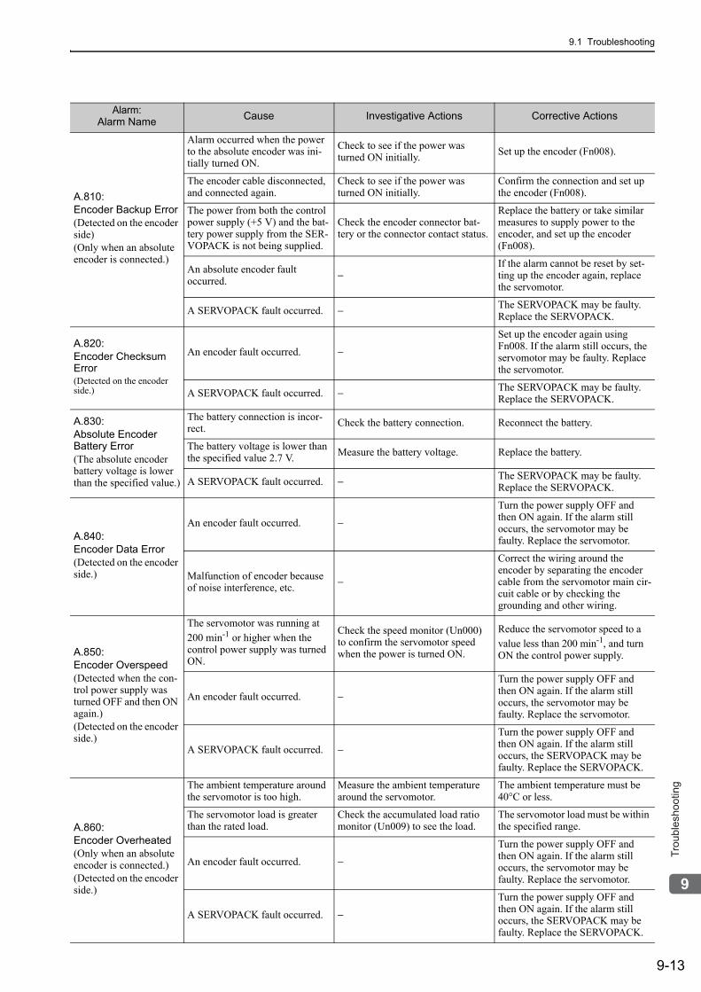
9.1 Troubleshooting
9-13
9
Tro
ub
lesh
oo
tin
g
A.810:Encoder Backup Error(Detected on the encoder side)(Only when an absolute encoder is connected.)
Alarm occurred when the power to the absolute encoder was ini-tially turned ON.
Check to see if the power was turned ON initially. Set up the encoder (Fn008).
The encoder cable disconnected, and connected again.
Check to see if the power was turned ON initially.
Confirm the connection and set up the encoder (Fn008).
The power from both the control power supply (+5 V) and the bat-tery power supply from the SER-VOPACK is not being supplied.
Check the encoder connector bat-tery or the connector contact status.
Replace the battery or take similar measures to supply power to the encoder, and set up the encoder (Fn008).
An absolute encoder fault occurred. −
If the alarm cannot be reset by set-ting up the encoder again, replace the servomotor.
A SERVOPACK fault occurred. − The SERVOPACK may be faulty. Replace the SERVOPACK.
A.820:Encoder Checksum Error(Detected on the encoder side.)
An encoder fault occurred. −
Set up the encoder again using Fn008. If the alarm still occurs, the servomotor may be faulty. Replace the servomotor.
A SERVOPACK fault occurred. − The SERVOPACK may be faulty. Replace the SERVOPACK.
A.830:Absolute Encoder Battery Error(The absolute encoder battery voltage is lower than the specified value.)
The battery connection is incor-rect. Check the battery connection. Reconnect the battery.
The battery voltage is lower than the specified value 2.7 V. Measure the battery voltage. Replace the battery.
A SERVOPACK fault occurred. − The SERVOPACK may be faulty. Replace the SERVOPACK.
A.840:Encoder Data Error(Detected on the encoder side.)
An encoder fault occurred. −
Turn the power supply OFF and then ON again. If the alarm still occurs, the servomotor may be faulty. Replace the servomotor.
Malfunction of encoder because of noise interference, etc. −
Correct the wiring around the encoder by separating the encoder cable from the servomotor main cir-cuit cable or by checking the grounding and other wiring.
A.850:Encoder Overspeed(Detected when the con-trol power supply was turned OFF and then ON again.)(Detected on the encoder side.)
The servomotor was running at 200 min-1 or higher when the control power supply was turned ON.
Check the speed monitor (Un000) to confirm the servomotor speed when the power is turned ON.
Reduce the servomotor speed to a value less than 200 min-1, and turn ON the control power supply.
An encoder fault occurred. −
Turn the power supply OFF and then ON again. If the alarm still occurs, the servomotor may be faulty. Replace the servomotor.
A SERVOPACK fault occurred. −
Turn the power supply OFF and then ON again. If the alarm still occurs, the SERVOPACK may be faulty. Replace the SERVOPACK.
A.860:Encoder Overheated(Only when an absolute encoder is connected.)(Detected on the encoder side.)
The ambient temperature around the servomotor is too high.
Measure the ambient temperature around the servomotor.
The ambient temperature must be 40°C or less.
The servomotor load is greater than the rated load.
Check the accumulated load ratio monitor (Un009) to see the load.
The servomotor load must be within the specified range.
An encoder fault occurred. −
Turn the power supply OFF and then ON again. If the alarm still occurs, the servomotor may be faulty. Replace the servomotor.
A SERVOPACK fault occurred. −
Turn the power supply OFF and then ON again. If the alarm still occurs, the SERVOPACK may be faulty. Replace the SERVOPACK.
Alarm:Alarm Name Cause Investigative Actions Corrective Actions
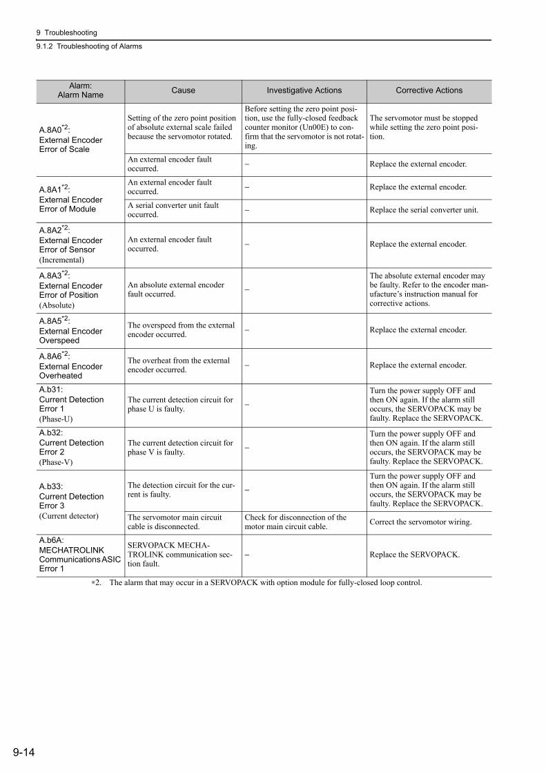
9 Troubleshooting
9.1.2 Troubleshooting of Alarms
9-14
A.8A0*2:External Encoder Error of Scale
Setting of the zero point position of absolute external scale failed because the servomotor rotated.
Before setting the zero point posi-tion, use the fully-closed feedback counter monitor (Un00E) to con-firm that the servomotor is not rotat-ing.
The servomotor must be stopped while setting the zero point posi-tion.
An external encoder fault occurred. − Replace the external encoder.
A.8A1*2:External Encoder Error of Module
An external encoder fault occurred. − Replace the external encoder.
A serial converter unit fault occurred. − Replace the serial converter unit.
A.8A2*2:External Encoder Error of Sensor(Incremental)
An external encoder fault occurred. − Replace the external encoder.
A.8A3*2:External Encoder Error of Position(Absolute)
An absolute external encoder fault occurred. −
The absolute external encoder may be faulty. Refer to the encoder man-ufacture’s instruction manual for corrective actions.
A.8A5*2:External Encoder Overspeed
The overspeed from the external encoder occurred. − Replace the external encoder.
A.8A6*2:External Encoder Overheated
The overheat from the external encoder occurred. − Replace the external encoder.
A.b31:Current Detection Error 1(Phase-U)
The current detection circuit for phase U is faulty. −
Turn the power supply OFF and then ON again. If the alarm still occurs, the SERVOPACK may be faulty. Replace the SERVOPACK.
A.b32:Current Detection Error 2(Phase-V)
The current detection circuit for phase V is faulty. −
Turn the power supply OFF and then ON again. If the alarm still occurs, the SERVOPACK may be faulty. Replace the SERVOPACK.
A.b33:Current Detection Error 3(Current detector)
The detection circuit for the cur-rent is faulty. −
Turn the power supply OFF and then ON again. If the alarm still occurs, the SERVOPACK may be faulty. Replace the SERVOPACK.
The servomotor main circuit cable is disconnected.
Check for disconnection of the motor main circuit cable. Correct the servomotor wiring.
A.b6A:MECHATROLINK Communications ASIC Error 1
SERVOPACK MECHA-TROLINK communication sec-tion fault.
− Replace the SERVOPACK.
∗2. The alarm that may occur in a SERVOPACK with option module for fully-closed loop control.
Alarm:Alarm Name Cause Investigative Actions Corrective Actions
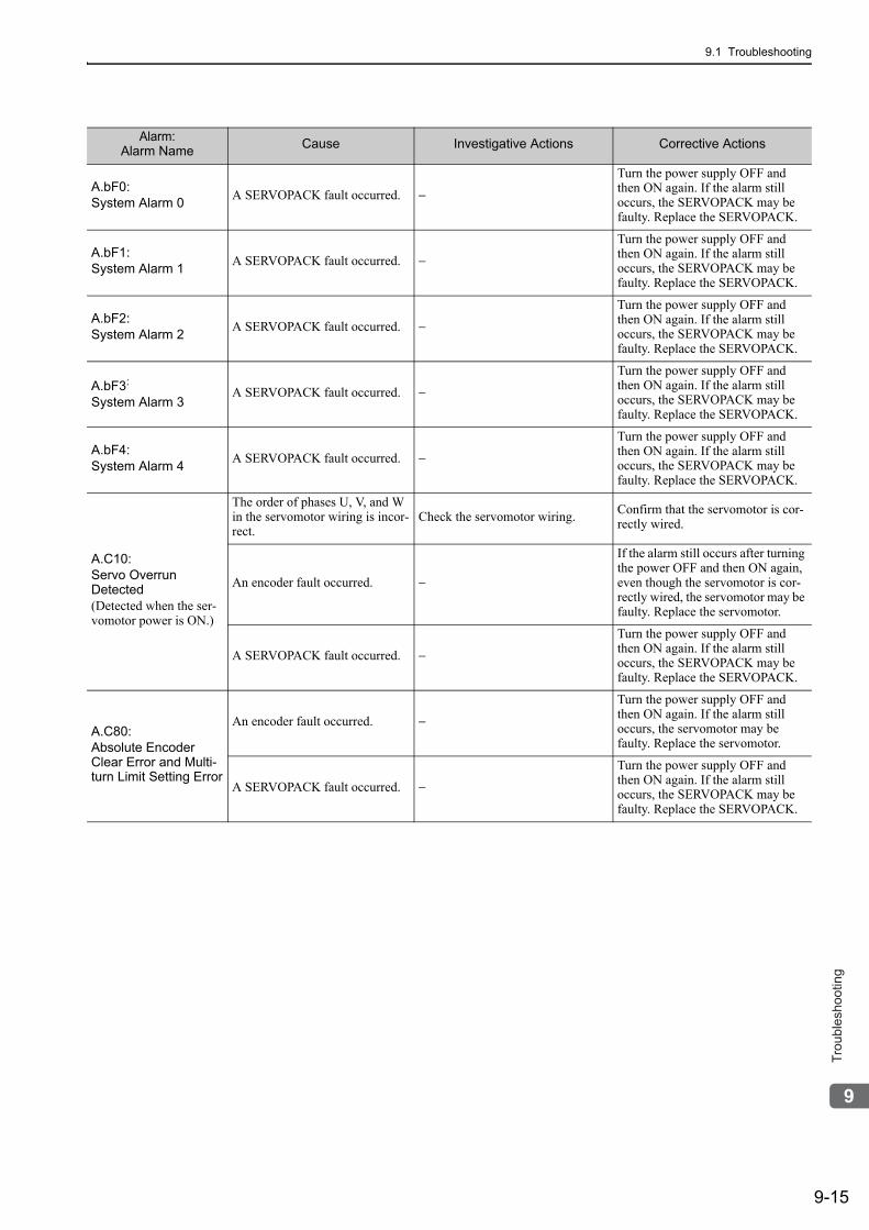
9.1 Troubleshooting
9-15
9
Tro
ub
lesh
oo
tin
g
A.bF0:System Alarm 0 A SERVOPACK fault occurred. −
Turn the power supply OFF and then ON again. If the alarm still occurs, the SERVOPACK may be faulty. Replace the SERVOPACK.
A.bF1:System Alarm 1 A SERVOPACK fault occurred. −
Turn the power supply OFF and then ON again. If the alarm still occurs, the SERVOPACK may be faulty. Replace the SERVOPACK.
A.bF2:System Alarm 2 A SERVOPACK fault occurred. −
Turn the power supply OFF and then ON again. If the alarm still occurs, the SERVOPACK may be faulty. Replace the SERVOPACK.
A.bF3:
System Alarm 3A SERVOPACK fault occurred. −
Turn the power supply OFF and then ON again. If the alarm still occurs, the SERVOPACK may be faulty. Replace the SERVOPACK.
A.bF4:System Alarm 4 A SERVOPACK fault occurred. −
Turn the power supply OFF and then ON again. If the alarm still occurs, the SERVOPACK may be faulty. Replace the SERVOPACK.
A.C10:Servo Overrun Detected(Detected when the ser-vomotor power is ON.)
The order of phases U, V, and W in the servomotor wiring is incor-rect.
Check the servomotor wiring. Confirm that the servomotor is cor-rectly wired.
An encoder fault occurred. −
If the alarm still occurs after turning the power OFF and then ON again, even though the servomotor is cor-rectly wired, the servomotor may be faulty. Replace the servomotor.
A SERVOPACK fault occurred. −
Turn the power supply OFF and then ON again. If the alarm still occurs, the SERVOPACK may be faulty. Replace the SERVOPACK.
A.C80:Absolute Encoder Clear Error and Multi-turn Limit Setting Error
An encoder fault occurred. −
Turn the power supply OFF and then ON again. If the alarm still occurs, the servomotor may be faulty. Replace the servomotor.
A SERVOPACK fault occurred. −
Turn the power supply OFF and then ON again. If the alarm still occurs, the SERVOPACK may be faulty. Replace the SERVOPACK.
Alarm:Alarm Name Cause Investigative Actions Corrective Actions
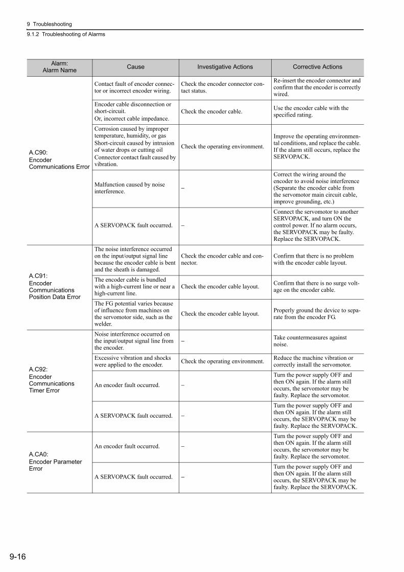
9 Troubleshooting
9.1.2 Troubleshooting of Alarms
9-16
A.C90:Encoder Communications Error
Contact fault of encoder connec-tor or incorrect encoder wiring.
Check the encoder connector con-tact status.
Re-insert the encoder connector and confirm that the encoder is correctly wired.
Encoder cable disconnection or short-circuit.Or, incorrect cable impedance.
Check the encoder cable. Use the encoder cable with the specified rating.
Corrosion caused by improper temperature, humidity, or gasShort-circuit caused by intrusion of water drops or cutting oilConnector contact fault caused by vibration.
Check the operating environment.
Improve the operating environmen-tal conditions, and replace the cable. If the alarm still occurs, replace the SERVOPACK.
Malfunction caused by noise interference. −
Correct the wiring around the encoder to avoid noise interference (Separate the encoder cable from the servomotor main circuit cable, improve grounding, etc.)
A SERVOPACK fault occurred. −
Connect the servomotor to another SERVOPACK, and turn ON the control power. If no alarm occurs, the SERVOPACK may be faulty. Replace the SERVOPACK.
A.C91:Encoder Communications Position Data Error
The noise interference occurred on the input/output signal line because the encoder cable is bent and the sheath is damaged.
Check the encoder cable and con-nector.
Confirm that there is no problem with the encoder cable layout.
The encoder cable is bundled with a high-current line or near a high-current line.
Check the encoder cable layout. Confirm that there is no surge volt-age on the encoder cable.
The FG potential varies because of influence from machines on the servomotor side, such as the welder.
Check the encoder cable layout. Properly ground the device to sepa-rate from the encoder FG.
A.C92:Encoder Communications Timer Error
Noise interference occurred on the input/output signal line from the encoder.
− Take countermeasures against noise.
Excessive vibration and shocks were applied to the encoder. Check the operating environment. Reduce the machine vibration or
correctly install the servomotor.
An encoder fault occurred. −
Turn the power supply OFF and then ON again. If the alarm still occurs, the servomotor may be faulty. Replace the servomotor.
A SERVOPACK fault occurred. −
Turn the power supply OFF and then ON again. If the alarm still occurs, the SERVOPACK may be faulty. Replace the SERVOPACK.
A.CA0:Encoder Parameter Error
An encoder fault occurred. −
Turn the power supply OFF and then ON again. If the alarm still occurs, the servomotor may be faulty. Replace the servomotor.
A SERVOPACK fault occurred. −
Turn the power supply OFF and then ON again. If the alarm still occurs, the SERVOPACK may be faulty. Replace the SERVOPACK.
Alarm:Alarm Name Cause Investigative Actions Corrective Actions
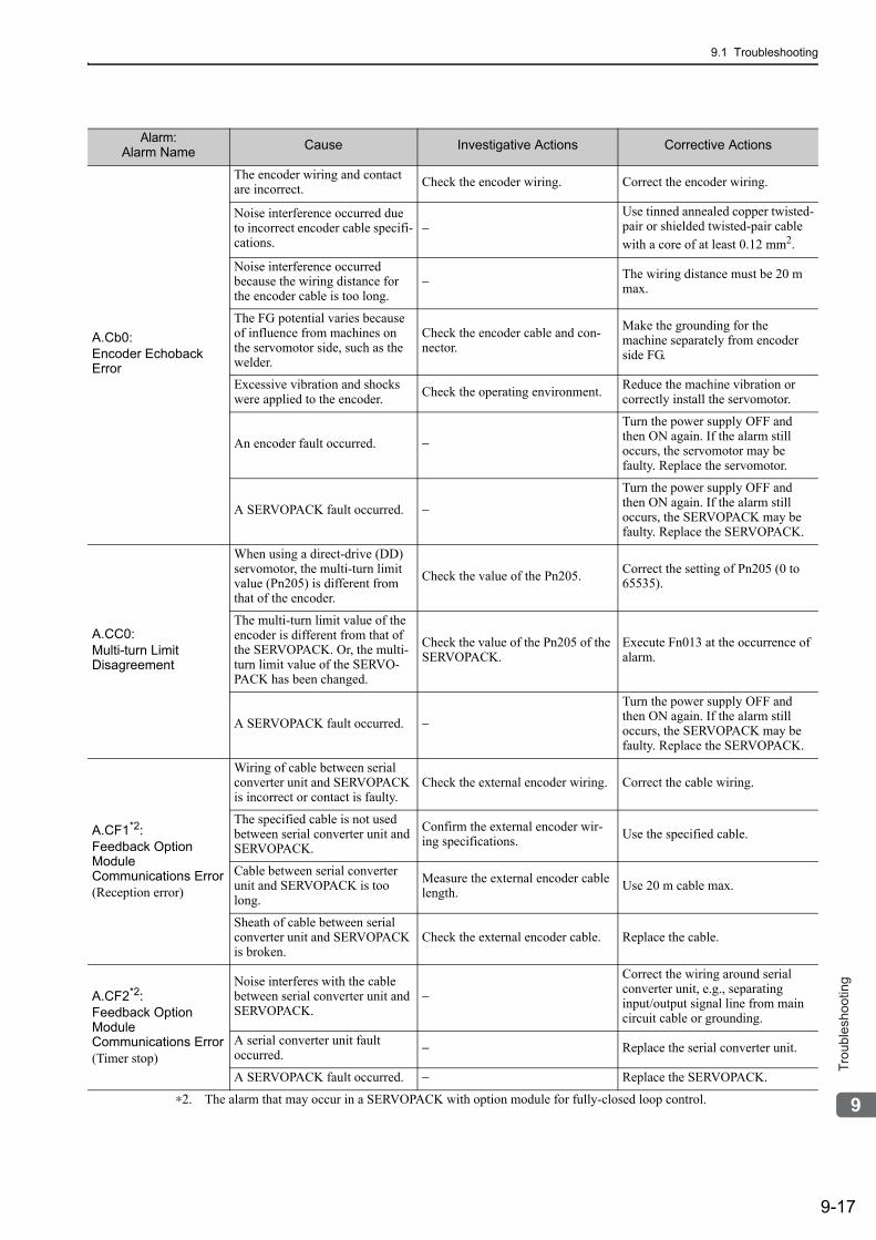
9.1 Troubleshooting
9-17
9
Tro
ub
lesh
oo
tin
g
A.Cb0:Encoder Echoback Error
The encoder wiring and contact are incorrect. Check the encoder wiring. Correct the encoder wiring.
Noise interference occurred due to incorrect encoder cable specifi-cations.
−Use tinned annealed copper twisted-pair or shielded twisted-pair cable with a core of at least 0.12 mm2.
Noise interference occurred because the wiring distance for the encoder cable is too long.
− The wiring distance must be 20 m max.
The FG potential varies because of influence from machines on the servomotor side, such as the welder.
Check the encoder cable and con-nector.
Make the grounding for the machine separately from encoder side FG.
Excessive vibration and shocks were applied to the encoder. Check the operating environment. Reduce the machine vibration or
correctly install the servomotor.
An encoder fault occurred. −
Turn the power supply OFF and then ON again. If the alarm still occurs, the servomotor may be faulty. Replace the servomotor.
A SERVOPACK fault occurred. −
Turn the power supply OFF and then ON again. If the alarm still occurs, the SERVOPACK may be faulty. Replace the SERVOPACK.
A.CC0:Multi-turn Limit Disagreement
When using a direct-drive (DD) servomotor, the multi-turn limit value (Pn205) is different from that of the encoder.
Check the value of the Pn205. Correct the setting of Pn205 (0 to 65535).
The multi-turn limit value of the encoder is different from that of the SERVOPACK. Or, the multi-turn limit value of the SERVO-PACK has been changed.
Check the value of the Pn205 of the SERVOPACK.
Execute Fn013 at the occurrence of alarm.
A SERVOPACK fault occurred. −
Turn the power supply OFF and then ON again. If the alarm still occurs, the SERVOPACK may be faulty. Replace the SERVOPACK.
A.CF1*2:Feedback Option Module Communications Error(Reception error)
Wiring of cable between serial converter unit and SERVOPACK is incorrect or contact is faulty.
Check the external encoder wiring. Correct the cable wiring.
The specified cable is not used between serial converter unit and SERVOPACK.
Confirm the external encoder wir-ing specifications. Use the specified cable.
Cable between serial converter unit and SERVOPACK is too long.
Measure the external encoder cable length. Use 20 m cable max.
Sheath of cable between serial converter unit and SERVOPACK is broken.
Check the external encoder cable. Replace the cable.
A.CF2*2:Feedback Option Module Communications Error(Timer stop)
Noise interferes with the cable between serial converter unit and SERVOPACK.
−
Correct the wiring around serial converter unit, e.g., separating input/output signal line from main circuit cable or grounding.
A serial converter unit fault occurred. − Replace the serial converter unit.
A SERVOPACK fault occurred. − Replace the SERVOPACK.
∗2. The alarm that may occur in a SERVOPACK with option module for fully-closed loop control.
Alarm:Alarm Name Cause Investigative Actions Corrective Actions
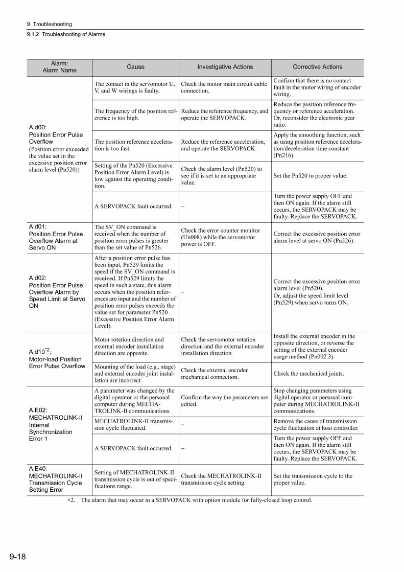
9 Troubleshooting
9.1.2 Troubleshooting of Alarms
9-18
A.d00:Position Error Pulse Overflow (Position error exceeded the value set in the excessive position error alarm level (Pn520))
The contact in the servomotor U, V, and W wirings is faulty.
Check the motor main circuit cable connection.
Confirm that there is no contact fault in the motor wiring of encoder wiring.
The frequency of the position ref-erence is too high.
Reduce the reference frequency, and operate the SERVOPACK.
Reduce the position reference fre-quency or reference acceleration. Or, reconsider the electronic gear ratio.
The position reference accelera-tion is too fast.
Reduce the reference acceleration, and operate the SERVOPACK.
Apply the smoothing function, such as using position reference accelera-tion/deceleration time constant (Pn216).
Setting of the Pn520 (Excessive Position Error Alarm Level) is low against the operating condi-tion.
Check the alarm level (Pn520) to see if it is set to an appropriate value.
Set the Pn520 to proper value.
A SERVOPACK fault occurred. −
Turn the power supply OFF and then ON again. If the alarm still occurs, the SERVOPACK may be faulty. Replace the SERVOPACK.
A.d01:Position Error Pulse Overflow Alarm at Servo ON
The SV_ON command is received when the number of position error pulses is greater than the set value of Pn526.
Check the error counter monitor (Un008) while the servomotor power is OFF.
Correct the excessive position error alarm level at servo ON (Pn526).
A.d02:Position Error Pulse Overflow Alarm by Speed Limit at Servo ON
After a position error pulse has been input, Pn529 limits the speed if the SV_ON command is received. If Pn529 limits the speed in such a state, this alarm occurs when the position refer-ences are input and the number of position error pulses exceeds the value set for parameter Pn520 (Excessive Position Error Alarm Level).
–
Correct the excessive position error alarm level (Pn520).Or, adjust the speed limit level (Pn529) when servo turns ON.
A.d10*2:Motor-load Position Error Pulse Overflow
Motor rotation direction and external encoder installation direction are opposite.
Check the servomotor rotation direction and the external encoder installation direction.
Install the external encoder in the opposite direction, or reverse the setting of the external encoder usage method (Pn002.3).
Mounting of the load (e.g., stage) and external encoder joint instal-lation are incorrect.
Check the external encoder mechanical connection. Check the mechanical joints.
A.E02:MECHATROLINK-II Internal Synchronization Error 1
A parameter was changed by the digital operator or the personal computer during MECHA-TROLINK-II communications.
Confirm the way the parameters are edited.
Stop changing parameters using digital operator or personal com-puter during MECHATROLINK-II communications.
MECHATROLINK-II transmis-sion cycle fluctuated. − Remove the cause of transmission
cycle fluctuation at host controller.
A SERVOPACK fault occurred. −
Turn the power supply OFF and then ON again. If the alarm still occurs, the SERVOPACK may be faulty. Replace the SERVOPACK.
A.E40:MECHATROLINK-II Transmission Cycle Setting Error
Setting of MECHATROLINK-II transmission cycle is out of speci-fications range.
Check the MECHATROLINK-II transmission cycle setting.
Set the transmission cycle to the proper value.
∗2. The alarm that may occur in a SERVOPACK with option module for fully-closed loop control.
Alarm:Alarm Name Cause Investigative Actions Corrective Actions
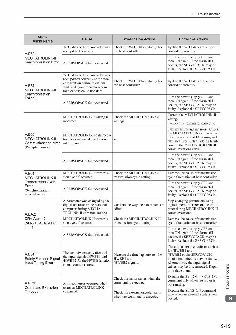
9.1 Troubleshooting
9-19
9
Tro
ub
lesh
oo
tin
g
A.E50:MECHATROLINK-II Synchronization Error
WDT data of host controller was not updated correctly.
Check the WDT data updating for the host controller.
Update the WDT data at the host controller correctly.
A SERVOPACK fault occurred. −
Turn the power supply OFF and then ON again. If the alarm still occurs, the SERVOPACK may be faulty. Replace the SERVOPACK.
A.E51:MECHATROLINK-II Synchronization Failed
WDT data of host controller was not updated correctly at the syn-chronization communications start, and synchronization com-munications could not start.
Check the WDT data updating for the host controller.
Update the WDT data at the host controller correctly.
A SERVOPACK fault occurred. −
Turn the power supply OFF and then ON again. If the alarm still occurs, the SERVOPACK may be faulty. Replace the SERVOPACK.
A.E60:MECHATROLINK-II Communications error(Reception error)
MECHATROLINK-II wiring is incorrect.
Check the MECHATROLINK-II wirings.
Correct the MECHATROLINK-II wiring.Connect the terminator correctly.
MECHATROLINK-II data recep-tion error occurred due to noise interference.
−
Take measures against noise. Check the MECHATROLINK-II commu-nications cable and FG wiring and take measures such as adding ferrite core on the MECHATROLINK-II communications cable.
A SERVOPACK fault occurred. −
Turn the power supply OFF and then ON again. If the alarm still occurs, the SERVOPACK may be faulty. Replace the SERVOPACK.
A.E61:MECHATROLINK-II Transmission Cycle Error(Synchronization interval error)
MECHATROLINK-II transmis-sion cycle fluctuated.
Check the MECHATROLINK-II transmission cycle setting.
Remove the cause of transmission cycle fluctuation at host controller.
A SERVOPACK fault occurred. −
Turn the power supply OFF and then ON again. If the alarm still occurs, the SERVOPACK may be faulty. Replace the SERVOPACK.
A.EA2:DRV Alarm 2(SERVOPACK WDC error)
A parameter was changed by the digital operator or the personal computer during MECHA-TROLINK-II communications.
Confirm the way the parameters are edited.
Stop changing parameters using digital operator or personal com-puter during MECHATROLINK-II communications.
MECHATROLINK-II transmis-sion cycle fluctuated.
Check the MECHATROLINK-II transmission cycle setting.
Remove the cause of transmission cycle fluctuation at host controller.
A SERVOPACK fault occurred. −
Turn the power supply OFF and then ON again. If the alarm still occurs, the SERVOPACK may be faulty. Replace the SERVOPACK.
A.Eb1:Safety Function Signal Input Timing Error
The lag between activations of the input signals /HWBB1 and /HWBB2 for the HWBB function is ten second or more.
Measure the time lag between the /HWBB1 and /HWBB2 signals.
The output signal circuits or devices for /HWBB1 and /HWBB2 or the SERVOPACK input signal circuits may be faulty. Alternatively, the input signal cables may be disconnected. Repair or replace them.
A.ED1:Command Execution Timeout
A timeout error occurred when using an MECHATROLINK command.
Check the motor status when the command is executed.
Execute the SV_ON or SENS_ON command only when the motor is not running.
Check the external encoder status when the command is executed.
Execute the SENS_ON command only when an external scale is con-nected.
Alarm:Alarm Name Cause Investigative Actions Corrective Actions
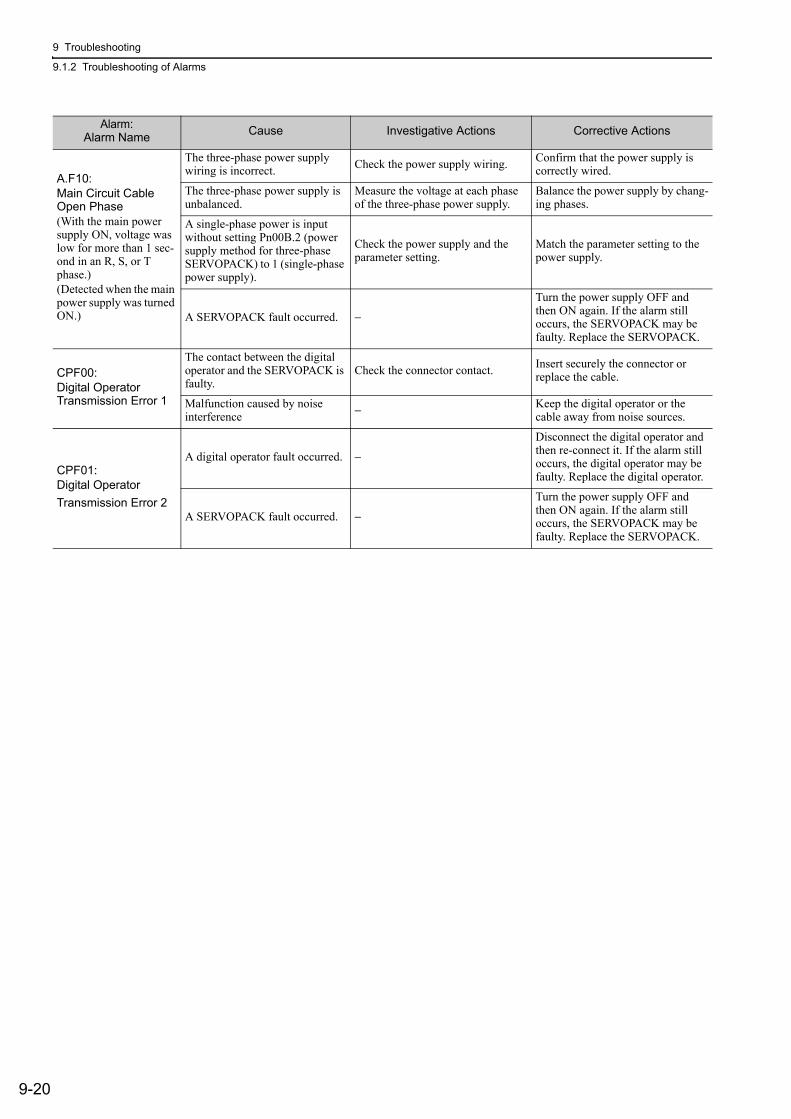
9 Troubleshooting
9.1.2 Troubleshooting of Alarms
9-20
A.F10:Main Circuit Cable Open Phase(With the main power supply ON, voltage was low for more than 1 sec-ond in an R, S, or T phase.)(Detected when the main power supply was turned ON.)
The three-phase power supply wiring is incorrect. Check the power supply wiring. Confirm that the power supply is
correctly wired.
The three-phase power supply is unbalanced.
Measure the voltage at each phase of the three-phase power supply.
Balance the power supply by chang-ing phases.
A single-phase power is input without setting Pn00B.2 (power supply method for three-phase SERVOPACK) to 1 (single-phase power supply).
Check the power supply and the parameter setting.
Match the parameter setting to the power supply.
A SERVOPACK fault occurred. −
Turn the power supply OFF and then ON again. If the alarm still occurs, the SERVOPACK may be faulty. Replace the SERVOPACK.
CPF00:Digital Operator Transmission Error 1
The contact between the digital operator and the SERVOPACK is faulty.
Check the connector contact. Insert securely the connector or replace the cable.
Malfunction caused by noise interference − Keep the digital operator or the
cable away from noise sources.
CPF01:Digital OperatorTransmission Error 2
A digital operator fault occurred. −
Disconnect the digital operator and then re-connect it. If the alarm still occurs, the digital operator may be faulty. Replace the digital operator.
A SERVOPACK fault occurred. −
Turn the power supply OFF and then ON again. If the alarm still occurs, the SERVOPACK may be faulty. Replace the SERVOPACK.
Alarm:Alarm Name Cause Investigative Actions Corrective Actions
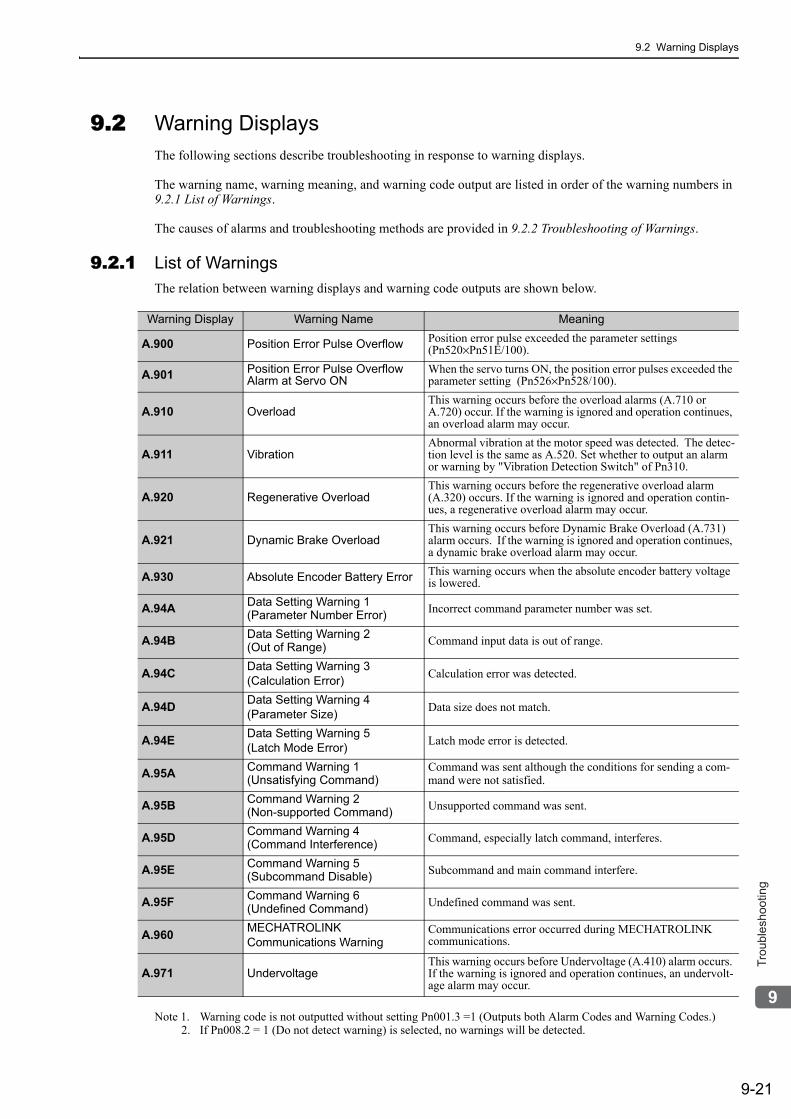
9.2 Warning Displays
9-21
9
Tro
ub
lesh
oo
tin
g
9.2 Warning DisplaysThe following sections describe troubleshooting in response to warning displays.
The warning name, warning meaning, and warning code output are listed in order of the warning numbers in 9.2.1 List of Warnings.
The causes of alarms and troubleshooting methods are provided in 9.2.2 Troubleshooting of Warnings.
9.2.1 List of WarningsThe relation between warning displays and warning code outputs are shown below.
Note 1. Warning code is not outputted without setting Pn001.3 =1 (Outputs both Alarm Codes and Warning Codes.)2. If Pn008.2 = 1 (Do not detect warning) is selected, no warnings will be detected.
Warning Display Warning Name Meaning
A.900 Position Error Pulse Overflow Position error pulse exceeded the parameter settings (Pn520×Pn51E/100).
A.901 Position Error Pulse Overflow Alarm at Servo ON
When the servo turns ON, the position error pulses exceeded the parameter setting (Pn526×Pn528/100).
A.910 OverloadThis warning occurs before the overload alarms (A.710 or A.720) occur. If the warning is ignored and operation continues, an overload alarm may occur.
A.911 VibrationAbnormal vibration at the motor speed was detected. The detec-tion level is the same as A.520. Set whether to output an alarm or warning by "Vibration Detection Switch" of Pn310.
A.920 Regenerative OverloadThis warning occurs before the regenerative overload alarm (A.320) occurs. If the warning is ignored and operation contin-ues, a regenerative overload alarm may occur.
A.921 Dynamic Brake OverloadThis warning occurs before Dynamic Brake Overload (A.731) alarm occurs. If the warning is ignored and operation continues, a dynamic brake overload alarm may occur.
A.930 Absolute Encoder Battery Error This warning occurs when the absolute encoder battery voltage is lowered.
A.94A Data Setting Warning 1(Parameter Number Error) Incorrect command parameter number was set.
A.94B Data Setting Warning 2(Out of Range) Command input data is out of range.
A.94C Data Setting Warning 3(Calculation Error) Calculation error was detected.
A.94D Data Setting Warning 4(Parameter Size) Data size does not match.
A.94E Data Setting Warning 5(Latch Mode Error) Latch mode error is detected.
A.95A Command Warning 1(Unsatisfying Command)
Command was sent although the conditions for sending a com-mand were not satisfied.
A.95B Command Warning 2(Non-supported Command) Unsupported command was sent.
A.95D Command Warning 4(Command Interference) Command, especially latch command, interferes.
A.95E Command Warning 5(Subcommand Disable) Subcommand and main command interfere.
A.95F Command Warning 6(Undefined Command) Undefined command was sent.
A.960 MECHATROLINKCommunications Warning
Communications error occurred during MECHATROLINK communications.
A.971 UndervoltageThis warning occurs before Undervoltage (A.410) alarm occurs. If the warning is ignored and operation continues, an undervolt-age alarm may occur.
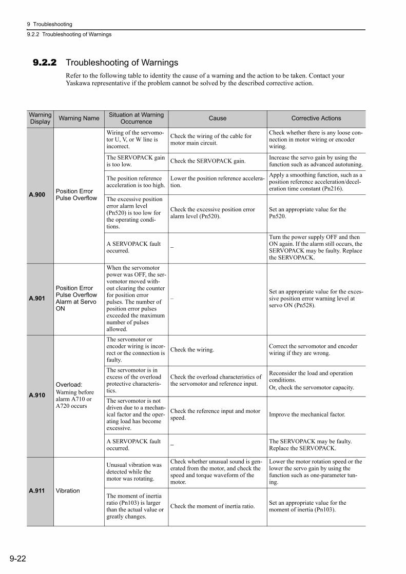
9 Troubleshooting
9.2.2 Troubleshooting of Warnings
9-22
9.2.2 Troubleshooting of WarningsRefer to the following table to identity the cause of a warning and the action to be taken. Contact your Yaskawa representative if the problem cannot be solved by the described corrective action.
Warning Display Warning Name Situation at Warning
Occurrence Cause Corrective Actions
A.900 Position Error Pulse Overflow
Wiring of the servomo-tor U, V, or W line is incorrect.
Check the wiring of the cable for motor main circuit.
Check whether there is any loose con-nection in motor wiring or encoder wiring.
The SERVOPACK gain is too low. Check the SERVOPACK gain. Increase the servo gain by using the
function such as advanced autotuning.
The position reference acceleration is too high.
Lower the position reference accelera-tion.
Apply a smoothing function, such as a position reference acceleration/decel-eration time constant (Pn216).
The excessive position error alarm level (Pn520) is too low for the operating condi-tions.
Check the excessive position error alarm level (Pn520).
Set an appropriate value for the Pn520.
A SERVOPACK fault occurred. −
Turn the power supply OFF and then ON again. If the alarm still occurs, the SERVOPACK may be faulty. Replace the SERVOPACK.
A.901Position Error Pulse Overflow Alarm at Servo ON
When the servomotor power was OFF, the ser-vomotor moved with-out clearing the counter for position error pulses. The number of position error pulses exceeded the maximum number of pulses allowed.
–Set an appropriate value for the exces-sive position error warning level at servo ON (Pn528).
A.910Overload:Warning before alarm A710 or A720 occurs
The servomotor or encoder wiring is incor-rect or the connection is faulty.
Check the wiring. Correct the servomotor and encoder wiring if they are wrong.
The servomotor is in excess of the overload protective characteris-tics.
Check the overload characteristics of the servomotor and reference input.
Reconsider the load and operation conditions.Or, check the servomotor capacity.
The servomotor is not driven due to a mechan-ical factor and the oper-ating load has become excessive.
Check the reference input and motor speed. Improve the mechanical factor.
A SERVOPACK fault occurred. − The SERVOPACK may be faulty.
Replace the SERVOPACK.
A.911 Vibration
Unusual vibration was detected while the motor was rotating.
Check whether unusual sound is gen-erated from the motor, and check the speed and torque waveform of the motor.
Lower the motor rotation speed or the lower the servo gain by using the function such as one-parameter tun-ing.
The moment of inertia ratio (Pn103) is larger than the actual value or greatly changes.
Check the moment of inertia ratio. Set an appropriate value for the moment of inertia (Pn103).
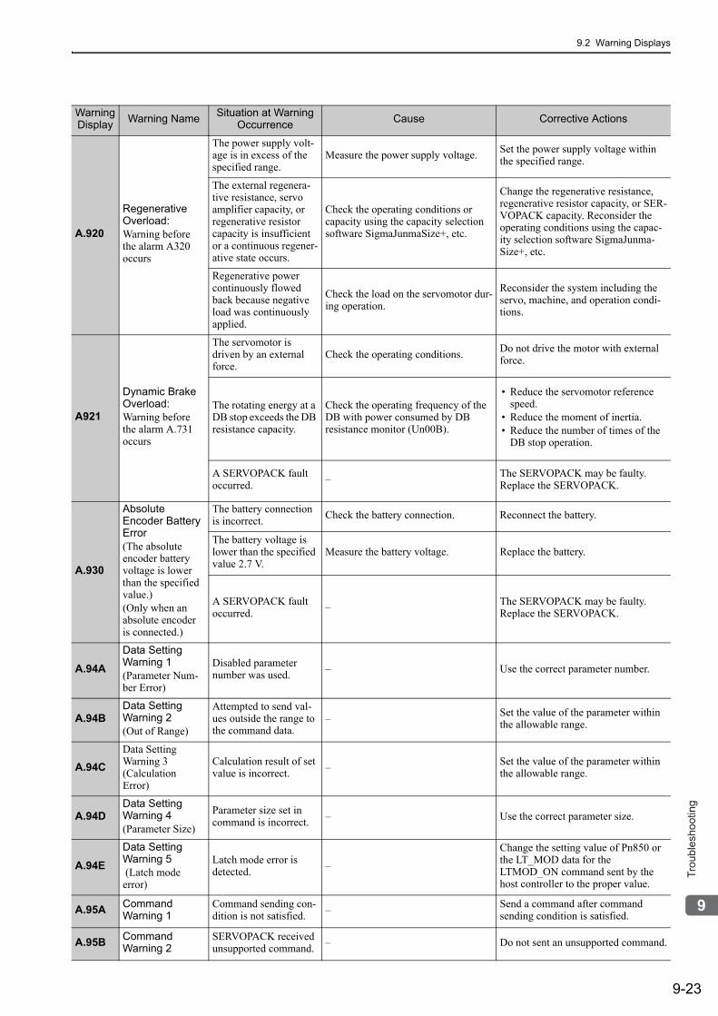
9.2 Warning Displays
9-23
9
Tro
ub
lesh
oo
tin
g
A.920
Regenerative Overload:Warning before the alarm A320 occurs
The power supply volt-age is in excess of the specified range.
Measure the power supply voltage. Set the power supply voltage within the specified range.
The external regenera-tive resistance, servo amplifier capacity, or regenerative resistor capacity is insufficient or a continuous regener-ative state occurs.
Check the operating conditions or capacity using the capacity selection software SigmaJunmaSize+, etc.
Change the regenerative resistance, regenerative resistor capacity, or SER-VOPACK capacity. Reconsider the operating conditions using the capac-ity selection software SigmaJunma-Size+, etc.
Regenerative power continuously flowed back because negative load was continuously applied.
Check the load on the servomotor dur-ing operation.
Reconsider the system including the servo, machine, and operation condi-tions.
A921
Dynamic Brake Overload: Warning before the alarm A.731 occurs
The servomotor is driven by an external force.
Check the operating conditions. Do not drive the motor with external force.
The rotating energy at a DB stop exceeds the DB resistance capacity.
Check the operating frequency of the DB with power consumed by DB resistance monitor (Un00B).
• Reduce the servomotor reference speed.
• Reduce the moment of inertia.• Reduce the number of times of the
DB stop operation.
A SERVOPACK fault occurred. – The SERVOPACK may be faulty.
Replace the SERVOPACK.
A.930
Absolute Encoder Battery Error(The absolute encoder battery voltage is lower than the specified value.)(Only when an absolute encoder is connected.)
The battery connection is incorrect. Check the battery connection. Reconnect the battery.
The battery voltage is lower than the specified value 2.7 V.
Measure the battery voltage. Replace the battery.
A SERVOPACK fault occurred. – The SERVOPACK may be faulty.
Replace the SERVOPACK.
A.94A Data Setting Warning 1(Parameter Num-ber Error)
Disabled parameter number was used. – Use the correct parameter number.
A.94BData Setting Warning 2(Out of Range)
Attempted to send val-ues outside the range to the command data.
– Set the value of the parameter within the allowable range.
A.94CData Setting Warning 3(Calculation Error)
Calculation result of set value is incorrect. – Set the value of the parameter within
the allowable range.
A.94DData Setting Warning 4(Parameter Size)
Parameter size set in command is incorrect. – Use the correct parameter size.
A.94EData Setting Warning 5 (Latch mode error)
Latch mode error is detected. –
Change the setting value of Pn850 or the LT_MOD data for the LTMOD_ON command sent by the host controller to the proper value.
A.95A Command Warning 1
Command sending con-dition is not satisfied. – Send a command after command
sending condition is satisfied.
A.95B Command Warning 2
SERVOPACK received unsupported command. – Do not sent an unsupported command.
Warning Display Warning Name Situation at Warning
Occurrence Cause Corrective Actions
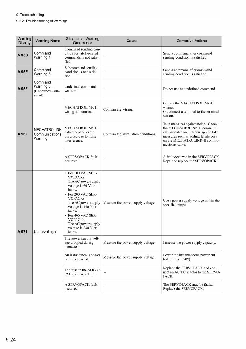
9 Troubleshooting
9.2.2 Troubleshooting of Warnings
9-24
A.95D Command Warning 4
Command sending con-dition for latch-related commands is not satis-fied.
– Send a command after command sending condition is satisfied.
A.95E Command Warning 5
Subcommand sending condition is not satis-fied.
– Send a command after command sending condition is satisfied.
A.95FCommand Warning 6(Undefined Com-mand)
Undefined command was sent. – Do not use an undefined command.
A.960MECHATROLINKCommunicationsWarning
MECHATROLINK-II wiring is incorrect. Confirm the wiring.
Correct the MECHATROLINK-II wiring.Or, connect a terminal to the terminal station.
MECHATROLINK-II data reception error occurred due to noise interference.
Confirm the installation conditions.
Take measures against noise. Check the MECHATROLINK-II communi-cations cable and FG wiring and take measures such as adding ferrite core on the MECHATROLINK-II commu-nications cable.
A SERVOPACK fault occurred. – A fault occurred in the SERVOPACK.
Repair or replace the SERVOPACK.
A.971 Undervoltage
• For 100 VAC SER-VOPACKs:The AC power supply voltage is 60 V or below.
• For 200 VAC SER-VOPACKs:The AC power supply voltage is 140 V or below.
• For 400 VAC SER-VOPACKs:The AC power supply voltage is 280 V or below.
Measure the power supply voltage. Use a power supply voltage within the specified range.
The power supply volt-age dropped during operation.
Measure the power supply voltage. Increase the power supply capacity.
An instantaneous power failure occurred. Measure the power supply voltage. Lower the instantaneous power cut
hold time (Pn509).
The fuse in the SERVO-PACK is burned out. –
Replace the SERVOPACK and con-nect an AC/DC reactor to the SERVO-PACK.
A SERVOPACK fault occurred. – The SERVOPACK may be faulty.
Replace the SERVOPACK.
Warning Display Warning Name Situation at Warning
Occurrence Cause Corrective Actions
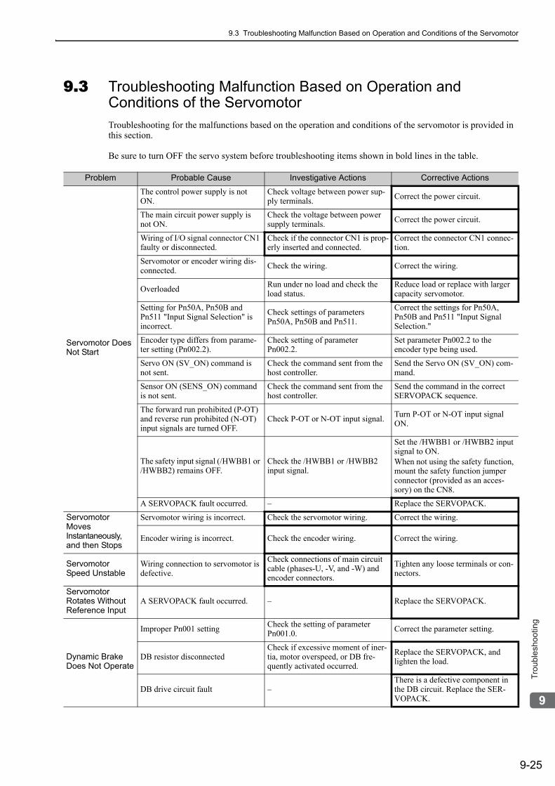
9.3 Troubleshooting Malfunction Based on Operation and Conditions of the Servomotor
9-25
9
Tro
ub
lesh
oo
tin
g
9.3 Troubleshooting Malfunction Based on Operation and Conditions of the ServomotorTroubleshooting for the malfunctions based on the operation and conditions of the servomotor is provided in this section.
Be sure to turn OFF the servo system before troubleshooting items shown in bold lines in the table.
Problem Probable Cause Investigative Actions Corrective Actions
Servomotor Does Not Start
The control power supply is not ON.
Check voltage between power sup-ply terminals. Correct the power circuit.
The main circuit power supply is not ON.
Check the voltage between power supply terminals. Correct the power circuit.
Wiring of I/O signal connector CN1 faulty or disconnected.
Check if the connector CN1 is prop-erly inserted and connected.
Correct the connector CN1 connec-tion.
Servomotor or encoder wiring dis-connected. Check the wiring. Correct the wiring.
Overloaded Run under no load and check the load status.
Reduce load or replace with larger capacity servomotor.
Setting for Pn50A, Pn50B and Pn511 "Input Signal Selection" is incorrect.
Check settings of parameters Pn50A, Pn50B and Pn511.
Correct the settings for Pn50A, Pn50B and Pn511 "Input Signal Selection."
Encoder type differs from parame-ter setting (Pn002.2).
Check setting of parameter Pn002.2.
Set parameter Pn002.2 to the encoder type being used.
Servo ON (SV_ON) command is not sent.
Check the command sent from the host controller.
Send the Servo ON (SV_ON) com-mand.
Sensor ON (SENS_ON) command is not sent.
Check the command sent from the host controller.
Send the command in the correct SERVOPACK sequence.
The forward run prohibited (P-OT) and reverse run prohibited (N-OT) input signals are turned OFF.
Check P-OT or N-OT input signal. Turn P-OT or N-OT input signal ON.
The safety input signal (/HWBB1 or /HWBB2) remains OFF.
Check the /HWBB1 or /HWBB2 input signal.
Set the /HWBB1 or /HWBB2 input signal to ON.When not using the safety function, mount the safety function jumper connector (provided as an acces-sory) on the CN8.
A SERVOPACK fault occurred. – Replace the SERVOPACK.
Servomotor Moves Instantaneously, and then Stops
Servomotor wiring is incorrect. Check the servomotor wiring. Correct the wiring.
Encoder wiring is incorrect. Check the encoder wiring. Correct the wiring.
Servomotor Speed Unstable
Wiring connection to servomotor is defective.
Check connections of main circuit cable (phases-U, -V, and -W) and encoder connectors.
Tighten any loose terminals or con-nectors.
Servomotor Rotates Without Reference Input
A SERVOPACK fault occurred. – Replace the SERVOPACK.
Dynamic Brake Does Not Operate
Improper Pn001 setting Check the setting of parameter Pn001.0. Correct the parameter setting.
DB resistor disconnectedCheck if excessive moment of iner-tia, motor overspeed, or DB fre-quently activated occurred.
Replace the SERVOPACK, and lighten the load.
DB drive circuit fault –There is a defective component in the DB circuit. Replace the SER-VOPACK.
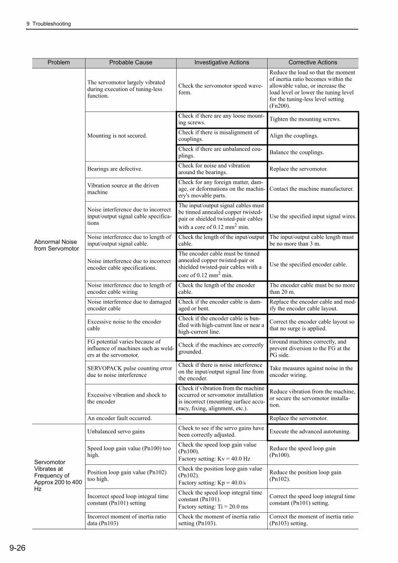
9 Troubleshooting
9-26
Abnormal Noise from Servomotor
The servomotor largely vibrated during execution of tuning-less function.
Check the servomotor speed wave-form.
Reduce the load so that the moment of inertia ratio becomes within the allowable value, or increase the load level or lower the tuning level for the tuning-less level setting (Fn200).
Mounting is not secured.
Check if there are any loose mount-ing screws. Tighten the mounting screws.
Check if there is misalignment of couplings. Align the couplings.
Check if there are unbalanced cou-plings. Balance the couplings.
Bearings are defective. Check for noise and vibration around the bearings. Replace the servomotor.
Vibration source at the driven machine
Check for any foreign matter, dam-age, or deformations on the machin-ery's movable parts.
Contact the machine manufacturer.
Noise interference due to incorrect input/output signal cable specifica-tions
The input/output signal cables must be tinned annealed copper twisted-pair or shielded twisted-pair cables with a core of 0.12 mm2 min.
Use the specified input signal wires.
Noise interference due to length of input/output signal cable.
Check the length of the input/output cable.
The input/output cable length must be no more than 3 m.
Noise interference due to incorrect encoder cable specifications.
The encoder cable must be tinned annealed copper twisted-pair or shielded twisted-pair cables with a core of 0.12 mm2 min.
Use the specified encoder cable.
Noise interference due to length of encoder cable wiring
Check the length of the encoder cable.
The encoder cable must be no more than 20 m.
Noise interference due to damaged encoder cable
Check if the encoder cable is dam-aged or bent.
Replace the encoder cable and mod-ify the encoder cable layout.
Excessive noise to the encoder cable
Check if the encoder cable is bun-dled with high-current line or near a high-current line.
Correct the encoder cable layout so that no surge is applied.
FG potential varies because of influence of machines such as weld-ers at the servomotor.
Check if the machines are correctly grounded.
Ground machines correctly, and prevent diversion to the FG at the PG side.
SERVOPACK pulse counting error due to noise interference
Check if there is noise interference on the input/output signal line from the encoder.
Take measures against noise in the encoder wiring.
Excessive vibration and shock to the encoder
Check if vibration from the machine occurred or servomotor installation is incorrect (mounting surface accu-racy, fixing, alignment, etc.).
Reduce vibration from the machine, or secure the servomotor installa-tion.
An encoder fault occurred. – Replace the servomotor.
Servomotor Vibrates at Frequency of Approx 200 to 400 Hz
Unbalanced servo gains Check to see if the servo gains have been correctly adjusted. Execute the advanced autotuning.
Speed loop gain value (Pn100) too high.
Check the speed loop gain value (Pn100).Factory setting: Kv = 40.0 Hz
Reduce the speed loop gain (Pn100).
Position loop gain value (Pn102) too high.
Check the position loop gain value (Pn102).Factory setting: Kp = 40.0/s
Reduce the position loop gain (Pn102).
Incorrect speed loop integral time constant (Pn101) setting
Check the speed loop integral time constant (Pn101).Factory setting: Ti = 20.0 ms
Correct the speed loop integral time constant (Pn101) setting.
Incorrect moment of inertia ratio data (Pn103)
Check the moment of inertia ratio setting (Pn103).
Correct the moment of inertia ratio (Pn103) setting.
Problem Probable Cause Investigative Actions Corrective Actions
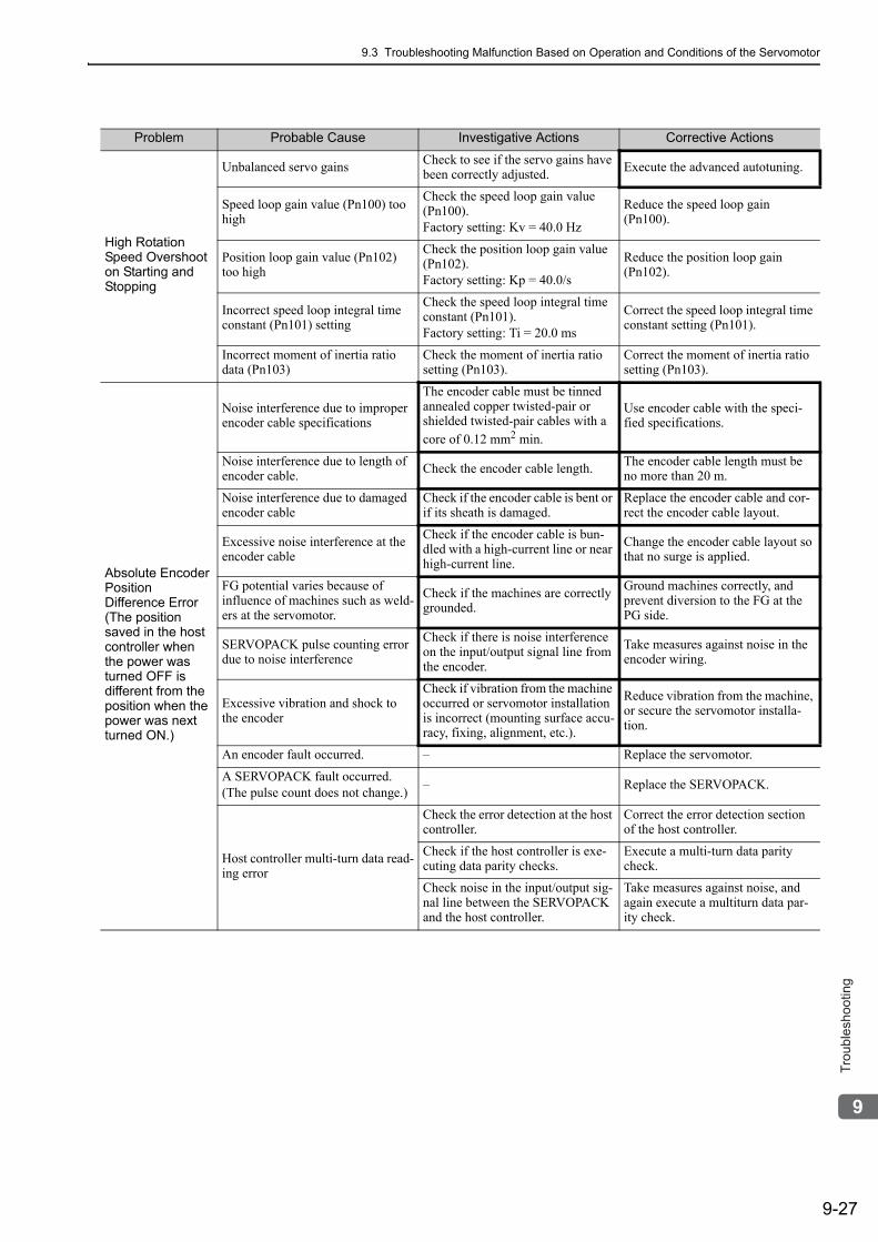
9.3 Troubleshooting Malfunction Based on Operation and Conditions of the Servomotor
9-27
9
Tro
ub
lesh
oo
tin
g
High Rotation Speed Overshoot on Starting and Stopping
Unbalanced servo gains Check to see if the servo gains have been correctly adjusted. Execute the advanced autotuning.
Speed loop gain value (Pn100) too high
Check the speed loop gain value (Pn100).Factory setting: Kv = 40.0 Hz
Reduce the speed loop gain (Pn100).
Position loop gain value (Pn102) too high
Check the position loop gain value (Pn102).Factory setting: Kp = 40.0/s
Reduce the position loop gain (Pn102).
Incorrect speed loop integral time constant (Pn101) setting
Check the speed loop integral time constant (Pn101).Factory setting: Ti = 20.0 ms
Correct the speed loop integral time constant setting (Pn101).
Incorrect moment of inertia ratio data (Pn103)
Check the moment of inertia ratio setting (Pn103).
Correct the moment of inertia ratio setting (Pn103).
Absolute Encoder Position Difference Error (The position saved in the host controller when the power was turned OFF is different from the position when the power was next turned ON.)
Noise interference due to improper encoder cable specifications
The encoder cable must be tinned annealed copper twisted-pair or shielded twisted-pair cables with a core of 0.12 mm2 min.
Use encoder cable with the speci-fied specifications.
Noise interference due to length of encoder cable. Check the encoder cable length. The encoder cable length must be
no more than 20 m.
Noise interference due to damaged encoder cable
Check if the encoder cable is bent or if its sheath is damaged.
Replace the encoder cable and cor-rect the encoder cable layout.
Excessive noise interference at the encoder cable
Check if the encoder cable is bun-dled with a high-current line or near high-current line.
Change the encoder cable layout so that no surge is applied.
FG potential varies because of influence of machines such as weld-ers at the servomotor.
Check if the machines are correctly grounded.
Ground machines correctly, and prevent diversion to the FG at the PG side.
SERVOPACK pulse counting error due to noise interference
Check if there is noise interference on the input/output signal line from the encoder.
Take measures against noise in the encoder wiring.
Excessive vibration and shock to the encoder
Check if vibration from the machine occurred or servomotor installation is incorrect (mounting surface accu-racy, fixing, alignment, etc.).
Reduce vibration from the machine, or secure the servomotor installa-tion.
An encoder fault occurred. – Replace the servomotor.
A SERVOPACK fault occurred.(The pulse count does not change.) – Replace the SERVOPACK.
Host controller multi-turn data read-ing error
Check the error detection at the host controller.
Correct the error detection section of the host controller.
Check if the host controller is exe-cuting data parity checks.
Execute a multi-turn data parity check.
Check noise in the input/output sig-nal line between the SERVOPACK and the host controller.
Take measures against noise, and again execute a multiturn data par-ity check.
Problem Probable Cause Investigative Actions Corrective Actions
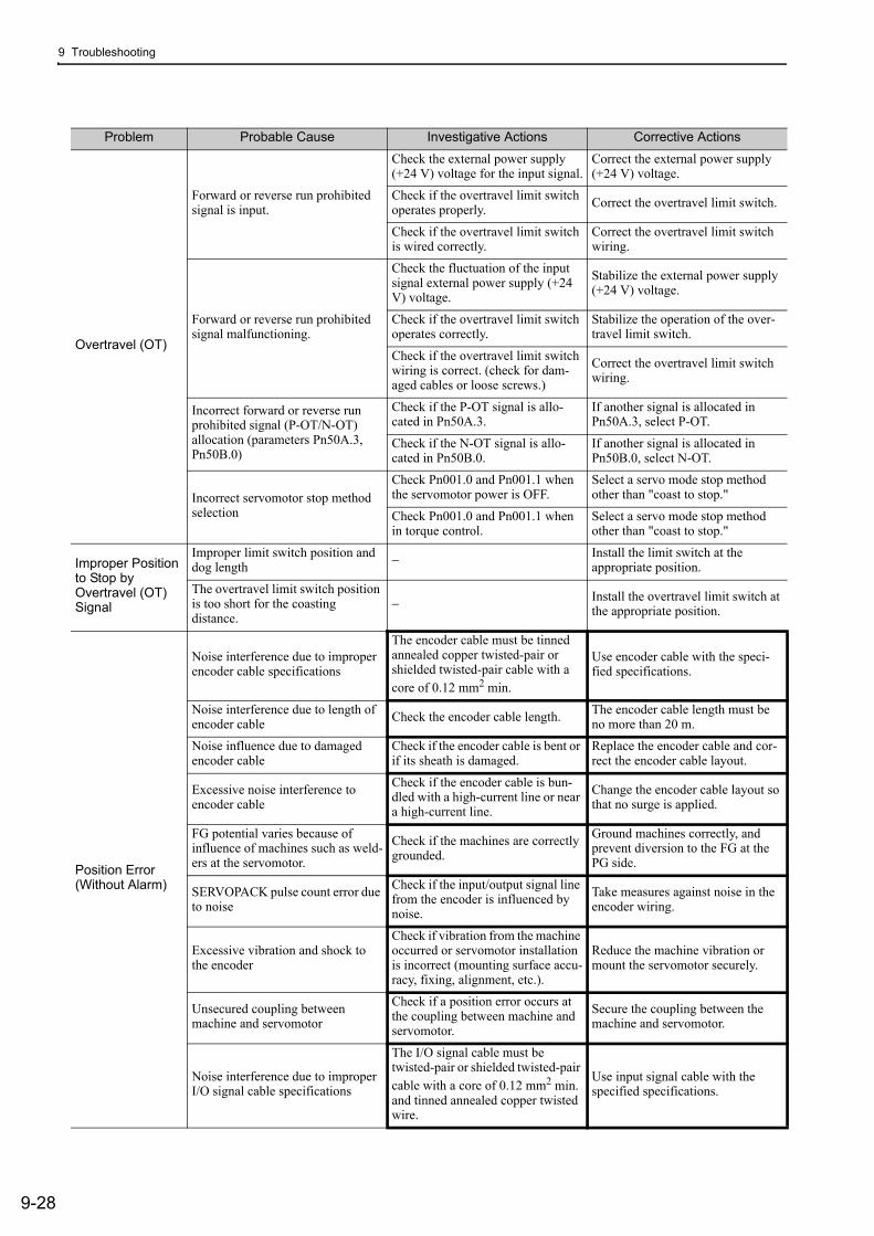
9 Troubleshooting
9-28
Overtravel (OT)
Forward or reverse run prohibited signal is input.
Check the external power supply (+24 V) voltage for the input signal.
Correct the external power supply (+24 V) voltage.
Check if the overtravel limit switch operates properly. Correct the overtravel limit switch.
Check if the overtravel limit switch is wired correctly.
Correct the overtravel limit switch wiring.
Forward or reverse run prohibited signal malfunctioning.
Check the fluctuation of the input signal external power supply (+24 V) voltage.
Stabilize the external power supply (+24 V) voltage.
Check if the overtravel limit switch operates correctly.
Stabilize the operation of the over-travel limit switch.
Check if the overtravel limit switch wiring is correct. (check for dam-aged cables or loose screws.)
Correct the overtravel limit switch wiring.
Incorrect forward or reverse run prohibited signal (P-OT/N-OT) allocation (parameters Pn50A.3, Pn50B.0)
Check if the P-OT signal is allo-cated in Pn50A.3.
If another signal is allocated in Pn50A.3, select P-OT.
Check if the N-OT signal is allo-cated in Pn50B.0.
If another signal is allocated in Pn50B.0, select N-OT.
Incorrect servomotor stop method selection
Check Pn001.0 and Pn001.1 when the servomotor power is OFF.
Select a servo mode stop method other than "coast to stop."
Check Pn001.0 and Pn001.1 when in torque control.
Select a servo mode stop method other than "coast to stop."
Improper Position to Stop by Overtravel (OT) Signal
Improper limit switch position and dog length − Install the limit switch at the
appropriate position.
The overtravel limit switch position is too short for the coasting distance.
− Install the overtravel limit switch at the appropriate position.
Position Error (Without Alarm)
Noise interference due to improper encoder cable specifications
The encoder cable must be tinned annealed copper twisted-pair or shielded twisted-pair cable with a core of 0.12 mm2 min.
Use encoder cable with the speci-fied specifications.
Noise interference due to length of encoder cable Check the encoder cable length. The encoder cable length must be
no more than 20 m.
Noise influence due to damaged encoder cable
Check if the encoder cable is bent or if its sheath is damaged.
Replace the encoder cable and cor-rect the encoder cable layout.
Excessive noise interference to encoder cable
Check if the encoder cable is bun-dled with a high-current line or near a high-current line.
Change the encoder cable layout so that no surge is applied.
FG potential varies because of influence of machines such as weld-ers at the servomotor.
Check if the machines are correctly grounded.
Ground machines correctly, and prevent diversion to the FG at the PG side.
SERVOPACK pulse count error due to noise
Check if the input/output signal line from the encoder is influenced by noise.
Take measures against noise in the encoder wiring.
Excessive vibration and shock to the encoder
Check if vibration from the machine occurred or servomotor installation is incorrect (mounting surface accu-racy, fixing, alignment, etc.).
Reduce the machine vibration or mount the servomotor securely.
Unsecured coupling between machine and servomotor
Check if a position error occurs at the coupling between machine and servomotor.
Secure the coupling between the machine and servomotor.
Noise interference due to improper I/O signal cable specifications
The I/O signal cable must be twisted-pair or shielded twisted-pair cable with a core of 0.12 mm2 min. and tinned annealed copper twisted wire.
Use input signal cable with the specified specifications.
Problem Probable Cause Investigative Actions Corrective Actions
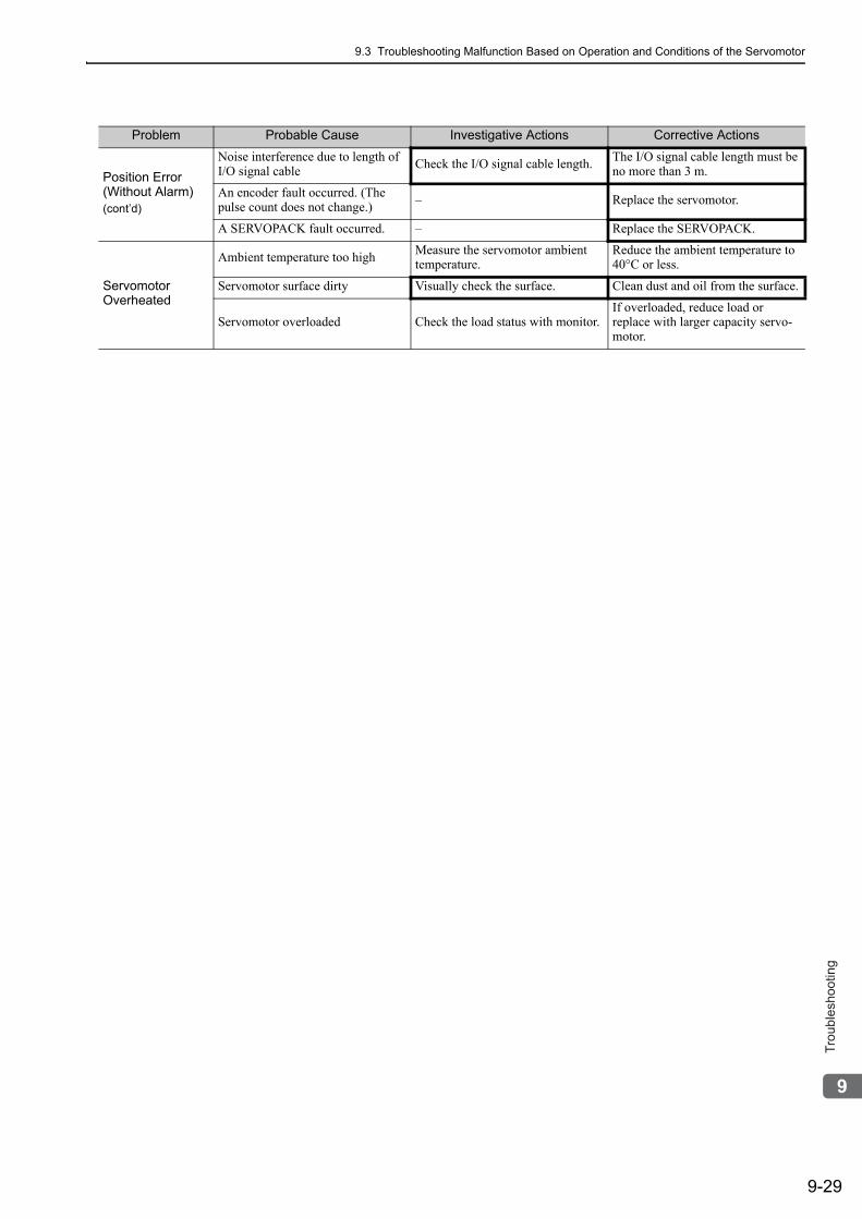
9.3 Troubleshooting Malfunction Based on Operation and Conditions of the Servomotor
9-29
9
Tro
ub
lesh
oo
tin
g
Position Error (Without Alarm)(cont’d)
Noise interference due to length of I/O signal cable Check the I/O signal cable length. The I/O signal cable length must be
no more than 3 m.
An encoder fault occurred. (The pulse count does not change.) – Replace the servomotor.
A SERVOPACK fault occurred. – Replace the SERVOPACK.
Servomotor Overheated
Ambient temperature too high Measure the servomotor ambient temperature.
Reduce the ambient temperature to 40°C or less.
Servomotor surface dirty Visually check the surface. Clean dust and oil from the surface.
Servomotor overloaded Check the load status with monitor.If overloaded, reduce load or replace with larger capacity servo-motor.
Problem Probable Cause Investigative Actions Corrective Actions
10-1
10
Ap
pe
nd
ix
10Appendix
10.1 List of Parameters . . . . . . . . . . . . . . . . . . . . . . . . . . . . . . . . . . . . . . . . . 10-210.1.1 Utility Functions . . . . . . . . . . . . . . . . . . . . . . . . . . . . . . . . . . . . . . . . . . . . . . . . . . . . 10-210.1.2 Parameters . . . . . . . . . . . . . . . . . . . . . . . . . . . . . . . . . . . . . . . . . . . . . . . . . . . . . . . 10-3
10.2 Monitor Modes . . . . . . . . . . . . . . . . . . . . . . . . . . . . . . . . . . . . . . . . . .10-32
10.3 Parameter Recording Table . . . . . . . . . . . . . . . . . . . . . . . . . . . . . . . .10-33
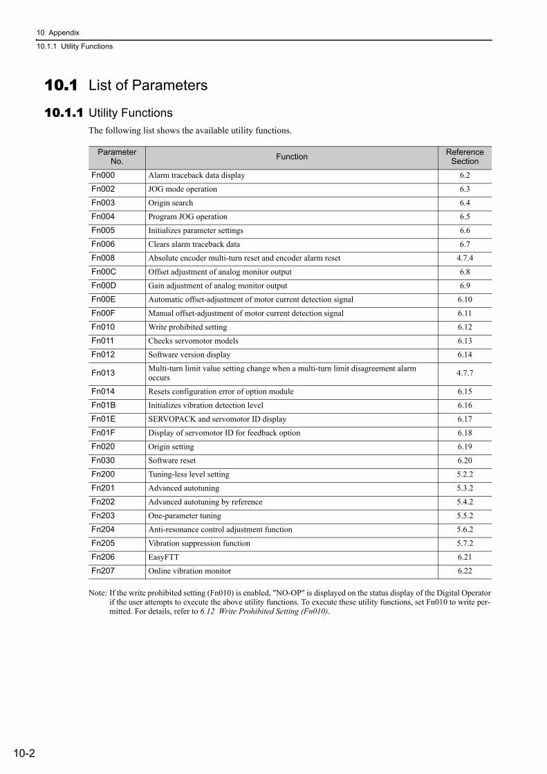
10 Appendix
10.1.1 Utility Functions
10-2
10.1 List of Parameters
10.1.1 Utility FunctionsThe following list shows the available utility functions.
Note: If the write prohibited setting (Fn010) is enabled, "NO-OP" is displayed on the status display of the Digital Operator if the user attempts to execute the above utility functions. To execute these utility functions, set Fn010 to write per-mitted. For details, refer to 6.12 Write Prohibited Setting (Fn010).
Parameter No. Function Reference
Section
Fn000 Alarm traceback data display 6.2
Fn002 JOG mode operation 6.3
Fn003 Origin search 6.4
Fn004 Program JOG operation 6.5
Fn005 Initializes parameter settings 6.6
Fn006 Clears alarm traceback data 6.7
Fn008 Absolute encoder multi-turn reset and encoder alarm reset 4.7.4
Fn00C Offset adjustment of analog monitor output 6.8
Fn00D Gain adjustment of analog monitor output 6.9
Fn00E Automatic offset-adjustment of motor current detection signal 6.10
Fn00F Manual offset-adjustment of motor current detection signal 6.11
Fn010 Write prohibited setting 6.12
Fn011 Checks servomotor models 6.13
Fn012 Software version display 6.14
Fn013 Multi-turn limit value setting change when a multi-turn limit disagreement alarm occurs 4.7.7
Fn014 Resets configuration error of option module 6.15
Fn01B Initializes vibration detection level 6.16
Fn01E SERVOPACK and servomotor ID display 6.17
Fn01F Display of servomotor ID for feedback option 6.18
Fn020 Origin setting 6.19
Fn030 Software reset 6.20
Fn200 Tuning-less level setting 5.2.2
Fn201 Advanced autotuning 5.3.2
Fn202 Advanced autotuning by reference 5.4.2
Fn203 One-parameter tuning 5.5.2
Fn204 Anti-resonance control adjustment function 5.6.2
Fn205 Vibration suppression function 5.7.2
Fn206 EasyFTT 6.21
Fn207 Online vibration monitor 6.22
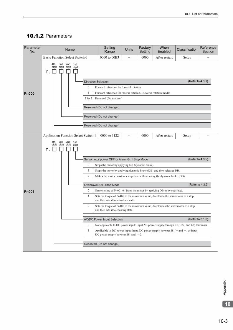
10.1 List of Parameters
10-3
10
Ap
pe
nd
ix
10.1.2 Parameters
Parameter No. Name Setting
Range Units Factory Setting
When Enabled Classification Reference
Section
Pn000
Basic Function Select Switch 0 0000 to 00B3 − 0000 After restart Setup −
Pn001
Application Function Select Switch 1 0000 to 1122 − 0000 After restart Setup −
0
1
2 to 3
Forward reference for forward rotation.
Forward reference for reverse rotation. (Reverse rotation mode)
Reserved (Do not use.)
Direction Selection
4thdigit
3rddigit
2nd digit
1stdigit
n.
Reserved (Do not change.)
Reserved (Do not change.)
Reserved (Do not change.)
(Refer to 4.3.1)
0
1
2
Stops the motor by applying DB (dynamic brake).
Stops the motor by applying dynamic brake (DB) and then releases DB.
Makes the motor coast to a stop state without using the dynamic brake (DB).
0
1
2
Same setting as Pn001.0 (Stops the motor by applying DB or by coasting).
Sets the torque of Pn406 to the maximum value, decelerate the servomotor to a stop, and then sets it to servolock state.
Sets the torque of Pn406 to the maximum value, decelerates the servomotor to a stop, and then sets it to coasting state.
Overtravel (OT) Stop Mode
4thdigit
3rddigit
2nd digit
1stdigit
n.
0
1
Not applicable to DC power input: Input AC power supply through L1, L2 (, and L3) terminals.
Applicable to DC power input: Input DC power supply between B1/ + and , or inputDC power supply between B1 and 2.
AC/DC Power Input Selection
Reserved (Do not change.)
Servomotor power OFF or Alarm Gr.1 Stop Mode (Refer to 4.3.5)
(Refer to 4.3.2)
(Refer to 3.1.5)
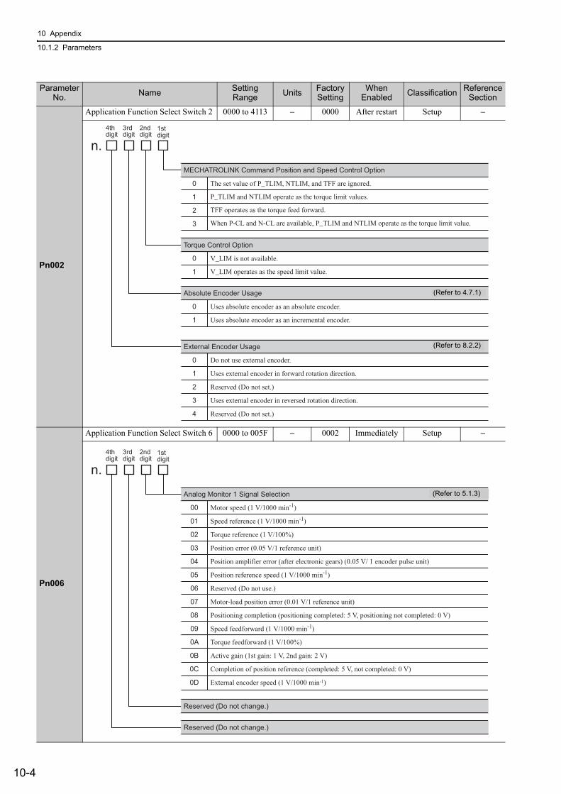
10 Appendix
10.1.2 Parameters
10-4
Pn002
Application Function Select Switch 2 0000 to 4113 − 0000 After restart Setup −
Pn006
Application Function Select Switch 6 0000 to 005F − 0002 Immediately Setup −
Parameter No. Name Setting
Range Units Factory Setting
When Enabled Classification Reference
Section
0
1
2
3
The set value of P_TLIM, NTLIM, and TFF are ignored.
P_TLIM and NTLIM operate as the torque limit values.
TFF operates as the torque feed forward.
When P-CL and N-CL are available, P_TLIM and NTLIM operate as the torque limit value.
MECHATROLINK Command Position and Speed Control Option
4th
digit
3rd
digit
2nd
digit1st
digit
n.
0
1
V_LIM is not available.
V_LIM operates as the speed limit value.
Torque Control Option
0
1
Uses absolute encoder as an absolute encoder.
Uses absolute encoder as an incremental encoder.
Absolute Encoder Usage
0
1
2
3
4
Do not use external encoder.
Uses external encoder in forward rotation direction.
Reserved (Do not set.)
Uses external encoder in reversed rotation direction.
Reserved (Do not set.)
External Encoder Usage
(Refer to 4.7.1)
(Refer to 8.2.2)
00
01
02
03
04
05
06
07
08
09
0A
0B
0C
0D
Motor speed (1 V/1000 min-1)
Speed reference (1 V/1000 min-1)
Torque reference (1 V/100%)
Position error (0.05 V/1 reference unit)
Position amplifier error (after electronic gears) (0.05 V/ 1 encoder pulse unit)
Position reference speed (1 V/1000 min-1)
Reserved (Do not use.)
Motor-load position error (0.01 V/1 reference unit)
Positioning completion (positioning completed: 5 V, positioning not completed: 0 V)
Speed feedforward (1 V/1000 min-1)
Torque feedforward (1 V/100%)
Active gain (1st gain: 1 V, 2nd gain: 2 V)
Completion of position reference (completed: 5 V, not completed: 0 V)
External encoder speed (1 V/1000 min-1)
Analog Monitor 1 Signal Selection
4thdigit
3rddigit
2nd digit
1stdigit
n.
Reserved (Do not change.)
Reserved (Do not change.)
(Refer to 5.1.3)
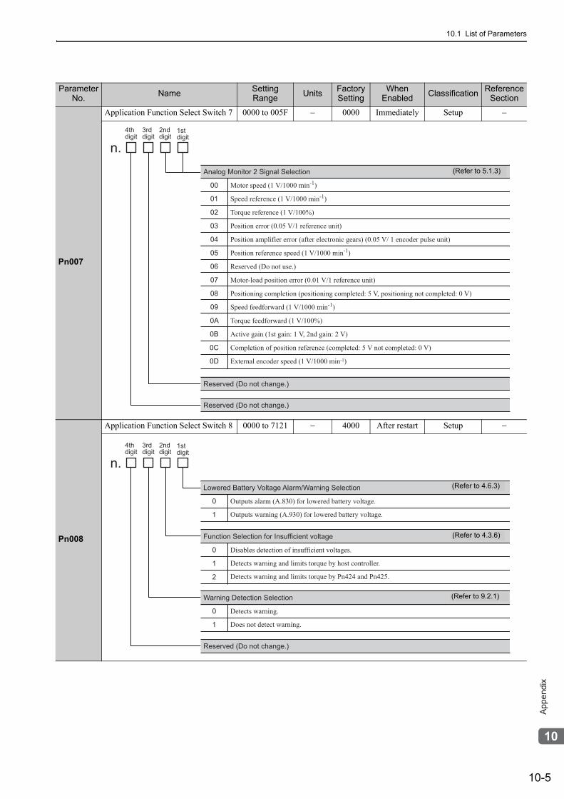
10.1 List of Parameters
10-5
10
Ap
pe
nd
ix
Pn007
Application Function Select Switch 7 0000 to 005F − 0000 Immediately Setup −
Pn008
Application Function Select Switch 8 0000 to 7121 − 4000 After restart Setup −
Parameter No. Name Setting
Range Units Factory Setting
When Enabled Classification Reference
Section
4thdigit
3rddigit
2nd digit
1stdigit
n.
Reserved (Do not change.)
Reserved (Do not change.)
00
01
02
03
04
05
06
07
08
09
0A
0B
0C
0D
Motor speed (1 V/1000 min-1)
Speed reference (1 V/1000 min-1)
Torque reference (1 V/100%)
Position error (0.05 V/1 reference unit)
Position amplifier error (after electronic gears) (0.05 V/ 1 encoder pulse unit)
Position reference speed (1 V/1000 min-1)
Reserved (Do not use.)
Motor-load position error (0.01 V/1 reference unit)
Positioning completion (positioning completed: 5 V, positioning not completed: 0 V)
Speed feedforward (1 V/1000 min-1)
Torque feedforward (1 V/100%)
Active gain (1st gain: 1 V, 2nd gain: 2 V)
Completion of position reference (completed: 5 V not completed: 0 V)
External encoder speed (1 V/1000 min-1)
Analog Monitor 2 Signal Selection (Refer to 5.1.3)
0
1
Outputs alarm (A.830) for lowered battery voltage.
Outputs warning (A.930) for lowered battery voltage.
Lowered Battery Voltage Alarm/Warning Selection
0
1
2
Disables detection of insufficient voltages.
Detects warning and limits torque by host controller.
Detects warning and limits torque by Pn424 and Pn425.
Function Selection for Insufficient voltage
4thdigit
3rddigit
2nd digit
1stdigit
n.
0
1
Detects warning.
Does not detect warning.
Warning Detection Selection
Reserved (Do not change.)
(Refer to 4.6.3)
(Refer to 4.3.6)
(Refer to 9.2.1)
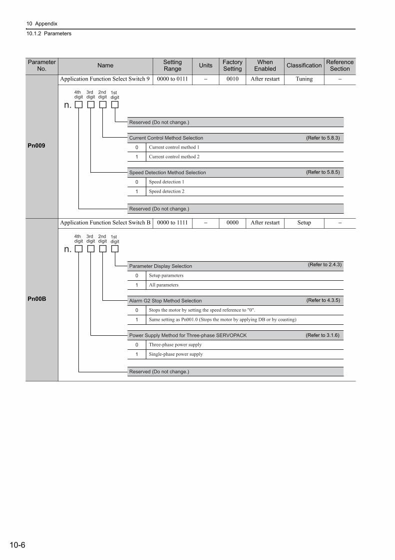
10 Appendix
10.1.2 Parameters
10-6
Pn009
Application Function Select Switch 9 0000 to 0111 − 0010 After restart Tuning −
Pn00B
Application Function Select Switch B 0000 to 1111 − 0000 After restart Setup −
Parameter No. Name Setting
Range Units Factory Setting
When Enabled Classification Reference
Section
0
1
Current Control Method Selection
Reserved (Do not change.)
Reserved (Do not change.)
4th
digit
3rd
digit
2nd
digit1st
digit
n.
Current control method 1
Current control method 2
0
1
Speed Detection Method Selection
Speed detection 1
Speed detection 2
(Refer to 5.8.3)
(Refer to 5.8.5)
0
1
Alarm G2 Stop Method Selection
Reserved (Do not change.)
4th
digit
3rd
digit
2nd
digit1st
digit
n.
Stops the motor by setting the speed reference to "0".
Same setting as Pn001.0 (Stops the motor by applying DB or by coasting)
0
1
Power Supply Method for Three-phase SERVOPACK
Three-phase power supply
Single-phase power supply
0
1
Parameter Display Selection
Setup parameters
All parameters
(Refer to 2.4.3)
(Refer to 4.3.5)
(Refer to 3.1.6)
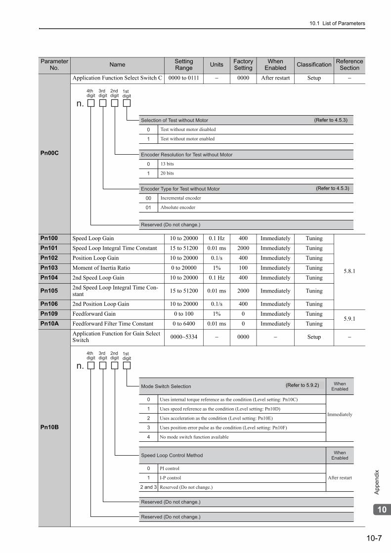
10.1 List of Parameters
10-7
10
Ap
pe
nd
ix
Pn00C
Application Function Select Switch C 0000 to 0111 − 0000 After restart Setup −
Pn100 Speed Loop Gain 10 to 20000 0.1 Hz 400 Immediately Tuning
5.8.1
Pn101 Speed Loop Integral Time Constant 15 to 51200 0.01 ms 2000 Immediately Tuning
Pn102 Position Loop Gain 10 to 20000 0.1/s 400 Immediately Tuning
Pn103 Moment of Inertia Ratio 0 to 20000 1% 100 Immediately Tuning
Pn104 2nd Speed Loop Gain 10 to 20000 0.1 Hz 400 Immediately Tuning
Pn105 2nd Speed Loop Integral Time Con-stant 15 to 51200 0.01 ms 2000 Immediately Tuning
Pn106 2nd Position Loop Gain 10 to 20000 0.1/s 400 Immediately Tuning
Pn109 Feedforward Gain 0 to 100 1% 0 Immediately Tuning5.9.1
Pn10A Feedforward Filter Time Constant 0 to 6400 0.01 ms 0 Immediately Tuning
Pn10B
Application Function for Gain Select Switch 0000∼5334 − 0000 − Setup −
Parameter No. Name Setting
Range Units Factory Setting
When Enabled Classification Reference
Section
0
1
Encoder Resolution for Test without Motor
Reserved (Do not change.)
4th
digit
3rd
digit
2nd
digit1st
digit
n.
13 bits
20 bits
0
1
Selection of Test without Motor
Test without motor disabled
Test without motor enabled
00
01
Encoder Type for Test without Motor
Incremental encoder
Absolute encoder
(Refer to 4.5.3)
(Refer to 4.5.3)
0
1
2
3
4
Uses internal torque reference as the condition (Level setting: Pn10C)
Uses speed reference as the condition (Level setting: Pn10D)
Uses acceleration as the condition (Level setting: Pn10E)
Uses position error pulse as the condition (Level setting: Pn10F)
No mode switch function available
Mode Switch Selection
Reserved (Do not change.)
4th
digit
3rd
digit
2nd
digit1st
digit
n.
Immediately
When
Enabled
0
1
2 and 3
PI control
I-P control
Reserved (Do not change.)
Speed Loop Control Method
After restart
When
Enabled
Reserved (Do not change.)
(Refer to 5.9.2)
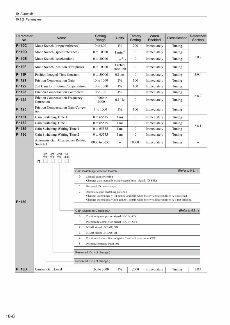
10 Appendix
10.1.2 Parameters
10-8
Pn10C Mode Switch (torque reference) 0 to 800 1% 200 Immediately Tuning
5.9.2Pn10D Mode Switch (speed reference) 0 to 10000 1 min-1 0 Immediately Tuning
Pn10E Mode Switch (acceleration) 0 to 30000 1 min-1/ s 0 Immediately Tuning
Pn10F Mode Switch (position error pulse) 0 to 10000 1 refer-ence unit 0 Immediately Tuning
Pn11F Position Integral Time Constant 0 to 50000 0.1 ms 0 Immediately Tuning 5.9.4
Pn121 Friction Compensation Gain 10 to 1000 1% 100 Immediately Tuning
5.8.2
Pn122 2nd Gain for Friction Compensation 10 to 1000 1% 100 Immediately Tuning
Pn123 Friction Compensation Coefficient 0 to 100 1% 0 Immediately Tuning
Pn124 Friction Compensation Frequency Correction
-10000 to 10000 0.1 Hz 0 Immediately Tuning
Pn125 Friction Compensation Gain Correc-tion 1 to 1000 1% 100 Immediately Tuning
Pn131 Gain Switching Time 1 0 to 65535 1 ms 0 Immediately Tuning
5.8.1Pn132 Gain Switching Time 2 0 to 65535 1 ms 0 Immediately Tuning
Pn135 Gain Switching Waiting Time 1 0 to 65535 1 ms 0 Immediately Tuning
Pn136 Gain Switching Waiting Time 2 0 to 65535 1 ms 0 Immediately Tuning
Pn139
Automatic Gain Changeover Related Switch 1 0000 to 0052 − 0000 Immediately Tuning −
Pn13D Current Gain Level 100 to 2000 1% 2000 Immediately Tuning 5.8.4
Parameter No. Name Setting
Range Units Factory Setting
When Enabled Classification Reference
Section
0
1
2
Manual gain switchingChanges gain manually using external input signals (G-SEL)
Reserved (Do not change.)
Automatic gain switching pattern 1Changes automatically 1st gain to 2nd gain when the switching condition A is satisfied.Changes automatically 2nd gain to 1st gain when the switching condition A is not satisfied.
Gain Switching Selection Switch
4thdigit
3rddigit
2nd digit
1stdigit
n.
0
1
2
3
4
5
Positioning completion signal (/COIN) ON
Positioning completion signal (/COIN) OFF
NEAR signal (/NEAR) ON
NEAR signal (/NEAR) OFF
Position reference filter output = 0 and reference input OFF
Position reference input ON
Gain Switching Condition A
Reserved (Do not change.)
Reserved (Do not change.)
(Refer to 5.8.1)
(Refer to 5.8.1)
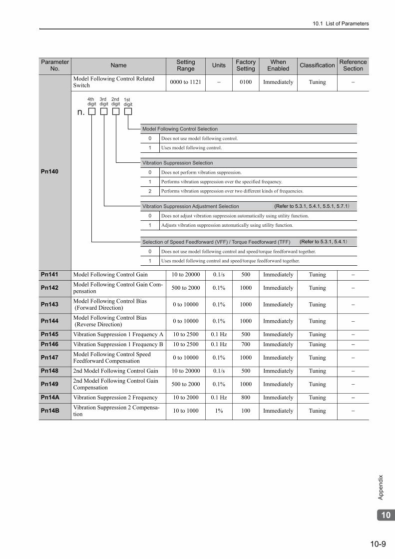
10.1 List of Parameters
10-9
10
Ap
pe
nd
ix
Pn140
Model Following Control Related Switch 0000 to 1121 − 0100 Immediately Tuning −
Pn141 Model Following Control Gain 10 to 20000 0.1/s 500 Immediately Tuning −
Pn142 Model Following Control Gain Com-pensation 500 to 2000 0.1% 1000 Immediately Tuning −
Pn143 Model Following Control Bias (Forward Direction) 0 to 10000 0.1% 1000 Immediately Tuning −
Pn144 Model Following Control Bias (Reverse Direction) 0 to 10000 0.1% 1000 Immediately Tuning −
Pn145 Vibration Suppression 1 Frequency A 10 to 2500 0.1 Hz 500 Immediately Tuning −
Pn146 Vibration Suppression 1 Frequency B 10 to 2500 0.1 Hz 700 Immediately Tuning −
Pn147 Model Following Control Speed Feedforward Compensation 0 to 10000 0.1% 1000 Immediately Tuning −
Pn148 2nd Model Following Control Gain 10 to 20000 0.1/s 500 Immediately Tuning −
Pn149 2nd Model Following Control Gain Compensation 500 to 2000 0.1% 1000 Immediately Tuning −
Pn14A Vibration Suppression 2 Frequency 10 to 2000 0.1 Hz 800 Immediately Tuning −
Pn14B Vibration Suppression 2 Compensa-tion 10 to 1000 1% 100 Immediately Tuning −
Parameter No. Name Setting
Range Units Factory Setting
When Enabled Classification Reference
Section
0
1
Does not use model following control.
Uses model following control.
Model Following Control Selection
4thdigit
3rddigit
2nd digit
1stdigit
n.
0
1
2
Does not perform vibration suppression.
Performs vibration suppression over the specified frequency.
Performs vibration suppression over two different kinds of frequencies.
Vibration Suppression Selection
0
1
Does not use model following control and speed/torque feedforward together.
Uses model following control and speed/torque feedforward together.
Selection of Speed Feedforward (VFF) / Torque Feedforward (TFF)
0
1
Does not adjust vibration suppression automatically using utility function.
Adjusts vibration suppression automatically using utility function.
Vibration Suppression Adjustment Selection (Refer to 5.3.1, 5.4.1, 5.5.1, 5.7.1)
(Refer to 5.3.1, 5.4.1)
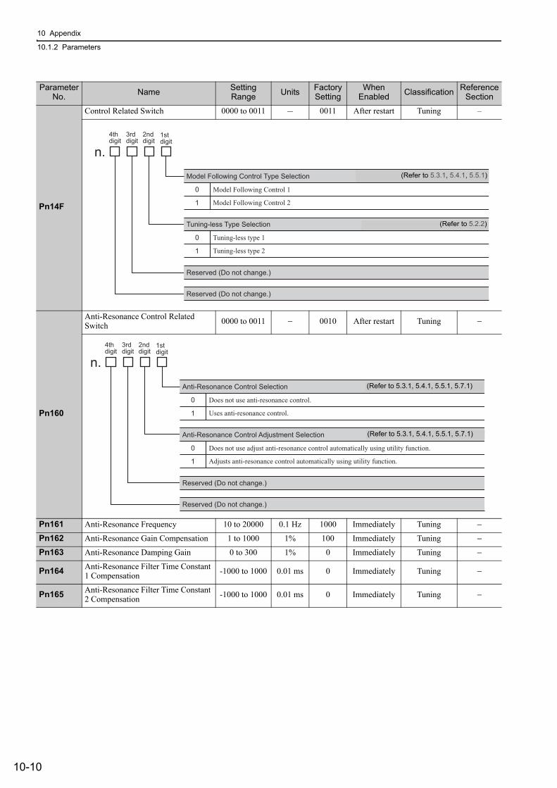
10 Appendix
10.1.2 Parameters
10-10
Pn14F
Control Related Switch 0000 to 0011 - 0011 After restart Tuning –
Pn160
Anti-Resonance Control Related Switch 0000 to 0011 − 0010 After restart Tuning −
Pn161 Anti-Resonance Frequency 10 to 20000 0.1 Hz 1000 Immediately Tuning −
Pn162 Anti-Resonance Gain Compensation 1 to 1000 1% 100 Immediately Tuning −
Pn163 Anti-Resonance Damping Gain 0 to 300 1% 0 Immediately Tuning −
Pn164 Anti-Resonance Filter Time Constant 1 Compensation -1000 to 1000 0.01 ms 0 Immediately Tuning −
Pn165 Anti-Resonance Filter Time Constant 2 Compensation -1000 to 1000 0.01 ms 0 Immediately Tuning −
Parameter No. Name Setting
Range Units Factory Setting
When Enabled Classification Reference
Section
0
1
Model Following Control 1
Model Following Control 2
Model Following Control Type Selection
4thdigit
3rddigit
2nd digit
1stdigit
n.
Reserved (Do not change.)
Reserved (Do not change.)
(Refer to 6.3.1, 6.4.1, 6.5.1)
0
1
Tuning-less type 1
Tuning-less type 2
Tuning-less Type Selection (Refer to 6.2.1)
(Refer to 5.3.1, 5.4.1, 5.5.1)
(Refer to 5.2.2)
0
1
Does not use anti-resonance control.
Uses anti-resonance control.
Anti-Resonance Control Selection
4th
digit
3rd
digit
2nd
digit1st
digit
n.
Reserved (Do not change.)
Reserved (Do not change.)
0
1
Does not use adjust anti-resonance control automatically using utility function.
Adjusts anti-resonance control automatically using utility function.
Anti-Resonance Control Adjustment Selection
(Refer to 5.3.1, 5.4.1, 5.5.1, 5.7.1)
(Refer to 5.3.1, 5.4.1, 5.5.1, 5.7.1)
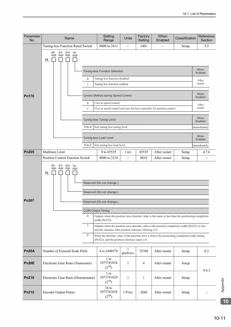
10.1 List of Parameters
10-11
10
Ap
pe
nd
ix
Pn170
Tuning-less Function Rated Switch 0000 to 2411 − 1401 − Setup 5.2
Pn205 Multiturn Limit 0 to 65535 1 rev 65535 After restart Setup 4.7.6
Pn207
Position Control Function Switch 0000 to 2210 − 0010 After restart Setup −
Pn20A Number of External Scale Pitch 4 to 1048576 1 pitch/rev 32768 After restart Setup 8.2
Pn20E Electronic Gear Ratio (Numerator)1 to
1073741824(230)
1 4 After restart Setup
4.4.3
Pn210 Electronic Gear Ratio (Denominator)1 to
1073741824(230)
1 1 After restart Setup
Pn212 Encoder Output Pulses16 to
1073741824(230)
1 P/rev 2048 After restart Setup −
Parameter No. Name Setting
Range Units Factory Setting
When Enabled Classification Reference
Section
0
1
Tuning-less function disabled
Tuning-less function enabled
Tuning-less Function Selection
4thdigit
3rddigit
2nd digit
1stdigit
n.
Afterrestart
WhenEnabled
0
1
Uses as speed control.
Uses as speed control and uses the host controller for position control.
Control Method during Speed Control
Afterrestart
WhenEnabled
0 to 4 Sets tuning-less tuning level.
Tuning-less Tuning Level
Immediaately
WhenEnabled
0 to 2 Sets tuning-less load level.
Tuning-less Load Level
Immediaately
WhenEnabled
4thdigit
3rddigit
2nd digit
1stdigit
n.
Reserved (Do not change.)
0
1
2
Outputs when the position error absolute value is the same or less than the positioning completion width (Pn522).
Outputs when the position error absolute value is the position completion width (Pn522) or less and the reference after position reference filtering is 0.
When the absolute value of the position error is below the positioning completed width setting (Pn522), and the position reference input is 0.
COIN Output Timing
Reserved (Do not change.)
Reserved (Do not change.)
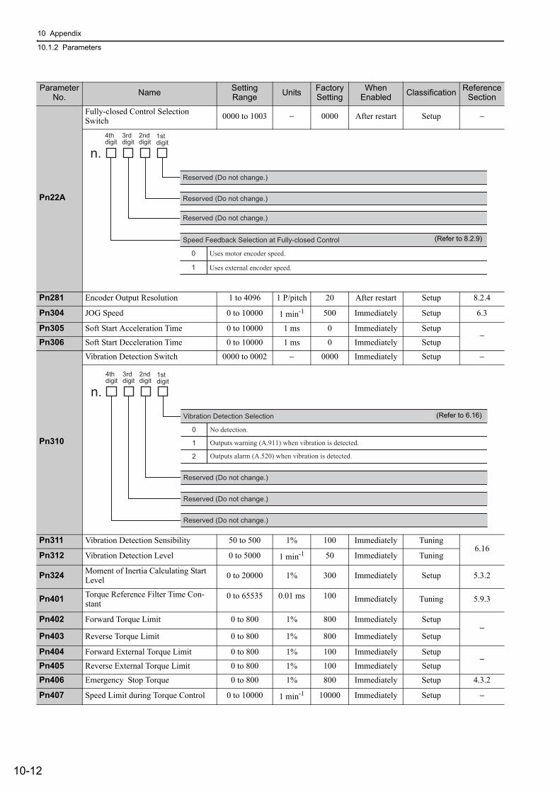
10 Appendix
10.1.2 Parameters
10-12
Pn22A
Fully-closed Control Selection Switch 0000 to 1003 − 0000 After restart Setup −
Pn281 Encoder Output Resolution 1 to 4096 1 P/pitch 20 After restart Setup 8.2.4
Pn304 JOG Speed 0 to 10000 1 min-1 500 Immediately Setup 6.3
Pn305 Soft Start Acceleration Time 0 to 10000 1 ms 0 Immediately Setup−
Pn306 Soft Start Deceleration Time 0 to 10000 1 ms 0 Immediately Setup
Pn310
Vibration Detection Switch 0000 to 0002 − 0000 Immediately Setup −
Pn311 Vibration Detection Sensibility 50 to 500 1% 100 Immediately Tuning6.16
Pn312 Vibration Detection Level 0 to 5000 1 min-1 50 Immediately Tuning
Pn324 Moment of Inertia Calculating Start Level 0 to 20000 1% 300 Immediately Setup 5.3.2
Pn401 Torque Reference Filter Time Con-stant
0 to 65535 0.01 ms 100 Immediately Tuning 5.9.3
Pn402 Forward Torque Limit 0 to 800 1% 800 Immediately Setup−
Pn403 Reverse Torque Limit 0 to 800 1% 800 Immediately Setup
Pn404 Forward External Torque Limit 0 to 800 1% 100 Immediately Setup−
Pn405 Reverse External Torque Limit 0 to 800 1% 100 Immediately Setup
Pn406 Emergency Stop Torque 0 to 800 1% 800 Immediately Setup 4.3.2
Pn407 Speed Limit during Torque Control 0 to 10000 1 min-1 10000 Immediately Setup −
Parameter No. Name Setting
Range Units Factory Setting
When Enabled Classification Reference
Section
4thdigit
3rddigit
2nd digit
1stdigit
n.
Reserved (Do not change.)
0
1
Uses motor encoder speed.
Uses external encoder speed.
Speed Feedback Selection at Fully-closed Control
Reserved (Do not change.)
Reserved (Do not change.)
(Refer to 8.2.9)
4th
digit
3rd
digit
2nd
digit1st
digit
n.
0
1
2
No detection.
Outputs warning (A.911) when vibration is detected.
Outputs alarm (A.520) when vibration is detected.
Vibration Detection Selection
Reserved (Do not change.)
Reserved (Do not change.)
Reserved (Do not change.)
(Refer to 6.16)
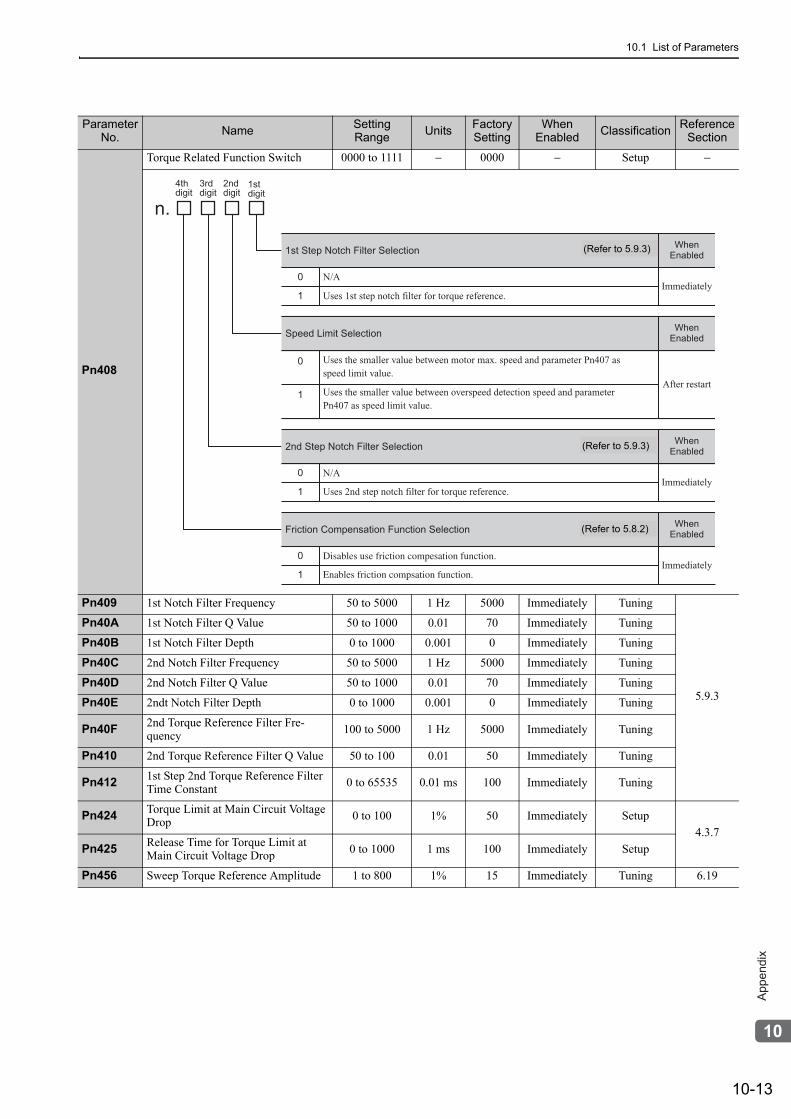
10.1 List of Parameters
10-13
10
Ap
pe
nd
ix
Pn408
Torque Related Function Switch 0000 to 1111 − 0000 − Setup −
Pn409 1st Notch Filter Frequency 50 to 5000 1 Hz 5000 Immediately Tuning
5.9.3
Pn40A 1st Notch Filter Q Value 50 to 1000 0.01 70 Immediately Tuning
Pn40B 1st Notch Filter Depth 0 to 1000 0.001 0 Immediately Tuning
Pn40C 2nd Notch Filter Frequency 50 to 5000 1 Hz 5000 Immediately Tuning
Pn40D 2nd Notch Filter Q Value 50 to 1000 0.01 70 Immediately Tuning
Pn40E 2ndt Notch Filter Depth 0 to 1000 0.001 0 Immediately Tuning
Pn40F 2nd Torque Reference Filter Fre-quency 100 to 5000 1 Hz 5000 Immediately Tuning
Pn410 2nd Torque Reference Filter Q Value 50 to 100 0.01 50 Immediately Tuning
Pn412 1st Step 2nd Torque Reference Filter Time Constant 0 to 65535 0.01 ms 100 Immediately Tuning
Pn424 Torque Limit at Main Circuit Voltage Drop 0 to 100 1% 50 Immediately Setup
4.3.7Pn425 Release Time for Torque Limit at
Main Circuit Voltage Drop 0 to 1000 1 ms 100 Immediately Setup
Pn456 Sweep Torque Reference Amplitude 1 to 800 1% 15 Immediately Tuning 6.19
Parameter No. Name Setting
Range Units Factory Setting
When Enabled Classification Reference
Section
4th
digit
3rd
digit
2nd
digit1st
digit
n.
When
Enabled
0
1
N/A
Uses 1st step notch filter for torque reference.
1st Step Notch Filter Selection
N/A
Uses 2nd step notch filter for torque reference.
2nd Step Notch Filter Selection
When
Enabled
When
Enabled
0
1
0
1
Uses the smaller value between motor max. speed and parameter Pn407 as speed limit value.
Uses the smaller value between overspeed detection speed and parameter Pn407 as speed limit value.
Speed Limit Selection
Disables use friction compesation function.
Enables friction compsation function.
Friction Compensation Function SelectionWhen
Enabled
0
1
Immediately
After restart
Immediately
Immediately
(Refer to 5.9.3)
(Refer to 5.9.3)
(Refer to 5.8.2)
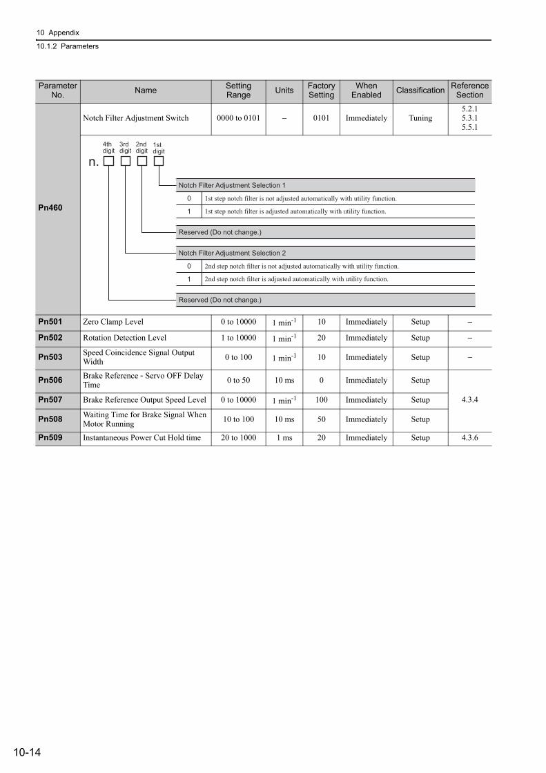
10 Appendix
10.1.2 Parameters
10-14
Pn460
Notch Filter Adjustment Switch 0000 to 0101 − 0101 Immediately Tuning5.2.15.3.15.5.1
Pn501 Zero Clamp Level 0 to 10000 1 min-1 10 Immediately Setup −
Pn502 Rotation Detection Level 1 to 10000 1 min-1 20 Immediately Setup −
Pn503 Speed Coincidence Signal Output Width 0 to 100 1 min-1 10 Immediately Setup −
Pn506 Brake Reference - Servo OFF Delay Time 0 to 50 10 ms 0 Immediately Setup
4.3.4Pn507 Brake Reference Output Speed Level 0 to 10000 1 min-1 100 Immediately Setup
Pn508 Waiting Time for Brake Signal When Motor Running 10 to 100 10 ms 50 Immediately Setup
Pn509 Instantaneous Power Cut Hold time 20 to 1000 1 ms 20 Immediately Setup 4.3.6
Parameter No. Name Setting
Range Units Factory Setting
When Enabled Classification Reference
Section
0
1
1st step notch filter is not adjusted automatically with utility function.
1st step notch filter is adjusted automatically with utility function.
Notch Filter Adjustment Selection 1
4th
digit
3rd
digit
2nd
digit1st
digit
n.
Reserved (Do not change.)
0
1
2nd step notch filter is not adjusted automatically with utility function.
2nd step notch filter is adjusted automatically with utility function.
Notch Filter Adjustment Selection 2
Reserved (Do not change.)

10.1 List of Parameters
10-15
10
Ap
pe
nd
ix
Pn50A
Input Signal Selection 1 0000 to FFF1 − 1881 After restart Setup −
Parameter No. Name Setting
Range Units Factory Setting
When Enabled Classification Reference
Section
4th
digit
3rd
digit
2nd
digit1st
digit
n.
0
1
2
3
4
5
6
7
8
9
A
B
C
D
E
F
Forward run allowed when CN1-13 input signal is ON (L-level)
Forward run allowed when CN1-7 input signal is ON (L-level)
Forward run allowed when CN1-8 input signal is ON (L-level)
Forward run allowed when CN1-9 input signal is ON (L-level)
Forward run allowed when CN1-10 input signal is ON (L-level)
Forward run allowed when CN1-11 input signal is ON (L-level)
Forward run allowed when CN1-12 input signal is ON (L-level)
Forward run prohibited
Forward run allowed
Forward run allowed when CN1-13 input signal is OFF (H-level)
Forward run allowed when CN1-7 input signal is OFF (H-level)
Forward run allowed when CN1-8 input signal is OFF (H-level)
Forward run allowed when CN1-9 input signal is OFF (H-level)
Forward run allowed when CN1-10 input signal is OFF (H-level)
Forward run allowed when CN1-11 input signal is OFF (H-level)
Forward run allowed when CN1-12 input signal is OFF (H-level)
P-OT Signal Mapping
Reserved (Do not change.)
Reserved (Do not change.)
Reserved (Do not change.)
(Refer to 4.3.2)
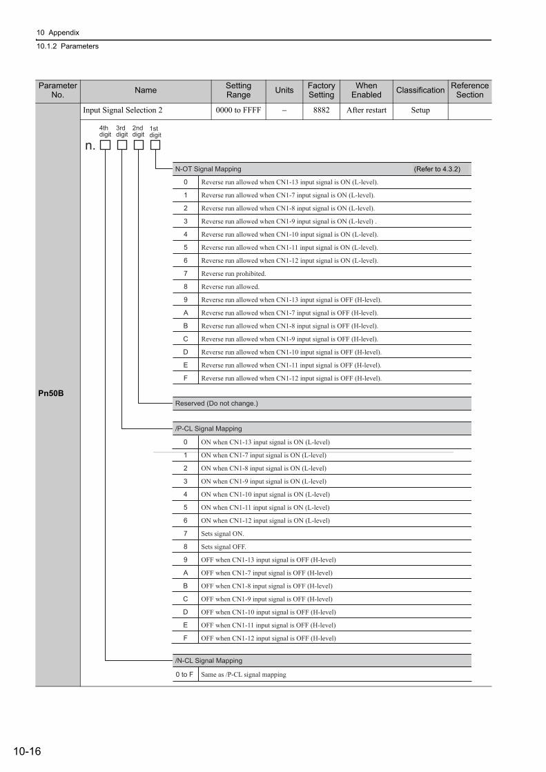
10 Appendix
10.1.2 Parameters
10-16
Pn50B
Input Signal Selection 2 0000 to FFFF − 8882 After restart Setup
Parameter No. Name Setting
Range Units Factory Setting
When Enabled Classification Reference
Section
4thdigit
3rddigit
2nd digit
1stdigit
n.
/P-CL Signal Mapping
N-OT Signal Mapping
0
1
2
3
4
5
6
7
8
9
A
B
C
D
E
F
Reverse run allowed when CN1-13 input signal is ON (L-level).
Reverse run allowed when CN1-7 input signal is ON (L-level).
Reverse run allowed when CN1-8 input signal is ON (L-level).
Reverse run allowed when CN1-9 input signal is ON (L-level) .
Reverse run allowed when CN1-10 input signal is ON (L-level).
Reverse run allowed when CN1-11 input signal is ON (L-level).
Reverse run allowed when CN1-12 input signal is ON (L-level).
Reverse run prohibited.
Reverse run allowed.
Reverse run allowed when CN1-13 input signal is OFF (H-level).
Reverse run allowed when CN1-7 input signal is OFF (H-level).
Reverse run allowed when CN1-8 input signal is OFF (H-level).
Reverse run allowed when CN1-9 input signal is OFF (H-level).
Reverse run allowed when CN1-10 input signal is OFF (H-level).
Reverse run allowed when CN1-11 input signal is OFF (H-level).
Reverse run allowed when CN1-12 input signal is OFF (H-level).
0 to F
/N-CL Signal Mapping
Reserved (Do not change.)
0
1
2
3
4
5
6
7
8
9
A
B
C
D
E
F
ON when CN1-13 input signal is ON (L-level)
ON when CN1-7 input signal is ON (L-level)
ON when CN1-8 input signal is ON (L-level)
ON when CN1-9 input signal is ON (L-level)
ON when CN1-10 input signal is ON (L-level)
ON when CN1-11 input signal is ON (L-level)
ON when CN1-12 input signal is ON (L-level)
Sets signal ON.
Sets signal OFF.
OFF when CN1-13 input signal is OFF (H-level)
OFF when CN1-7 input signal is OFF (H-level)
OFF when CN1-8 input signal is OFF (H-level)
OFF when CN1-9 input signal is OFF (H-level)
OFF when CN1-10 input signal is OFF (H-level)
OFF when CN1-11 input signal is OFF (H-level)
OFF when CN1-12 input signal is OFF (H-level)
Same as /P-CL signal mapping
(Refer to 4.3.2)
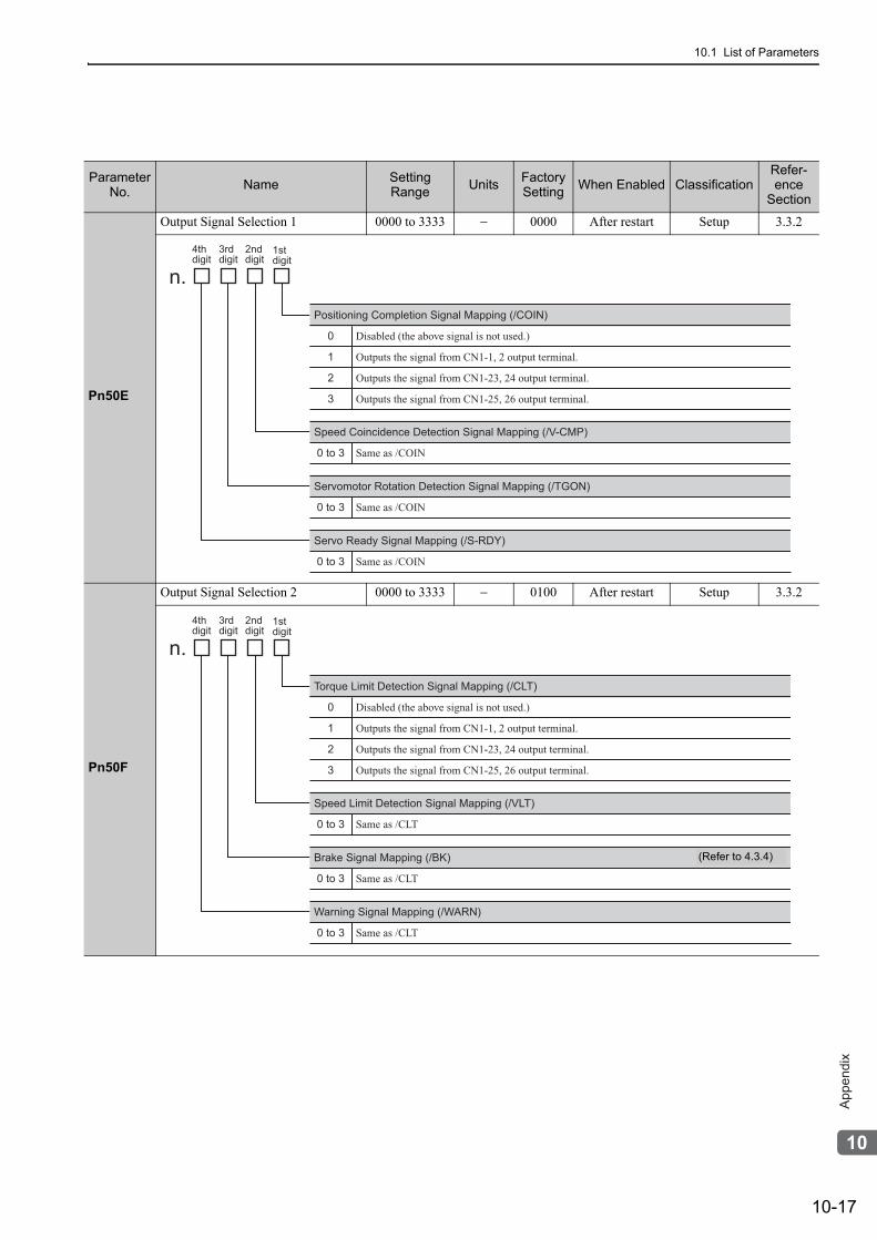
10.1 List of Parameters
10-17
10
Ap
pe
nd
ix
Parameter No. Name Setting
Range Units Factory Setting When Enabled Classification
Refer-ence
Section
Pn50E
Output Signal Selection 1 0000 to 3333 − 0000 After restart Setup 3.3.2
Pn50F
Output Signal Selection 2 0000 to 3333 − 0100 After restart Setup 3.3.2
4th
digit
3rd
digit
2nd
digit1st
digit
n.
0 to 3 Same as /COIN
Servomotor Rotation Detection Signal Mapping (/TGON)
Positioning Completion Signal Mapping (/COIN)
0
1
2
3
0 to 3 Same as /COIN
Speed Coincidence Detection Signal Mapping (/V-CMP)
0 to 3 Same as /COIN
Servo Ready Signal Mapping (/S-RDY)
Disabled (the above signal is not used.)
Outputs the signal from CN1-1, 2 output terminal.
Outputs the signal from CN1-23, 24 output terminal.
Outputs the signal from CN1-25, 26 output terminal.
4th
digit
3rd
digit
2nd
digit1st
digit
n.
0 to 3 Same as /CLT
Brake Signal Mapping (/BK)
Torque Limit Detection Signal Mapping (/CLT)
0
1
2
3
0 to 3 Same as /CLT
Speed Limit Detection Signal Mapping (/VLT)
0 to 3 Same as /CLT
Warning Signal Mapping (/WARN)
Disabled (the above signal is not used.)
Outputs the signal from CN1-1, 2 output terminal.
Outputs the signal from CN1-23, 24 output terminal.
Outputs the signal from CN1-25, 26 output terminal.
(Refer to 4.3.4)
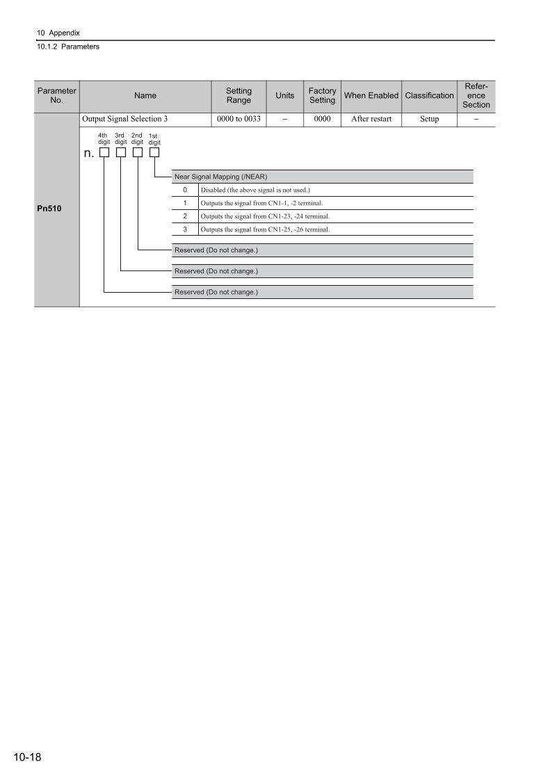
10 Appendix
10.1.2 Parameters
10-18
Pn510
Output Signal Selection 3 0000 to 0033 − 0000 After restart Setup −
Parameter No. Name Setting
Range Units Factory Setting When Enabled Classification
Refer-ence
Section
4thdigit
3rddigit
2nd digit
1stdigit
n.
Near Signal Mapping (/NEAR)
0
1
2
3
Reserved (Do not change.)
Disabled (the above signal is not used.)
Outputs the signal from CN1-1, -2 terminal.
Outputs the signal from CN1-23, -24 terminal.
Outputs the signal from CN1-25, -26 terminal.
Reserved (Do not change.)
Reserved (Do not change.)
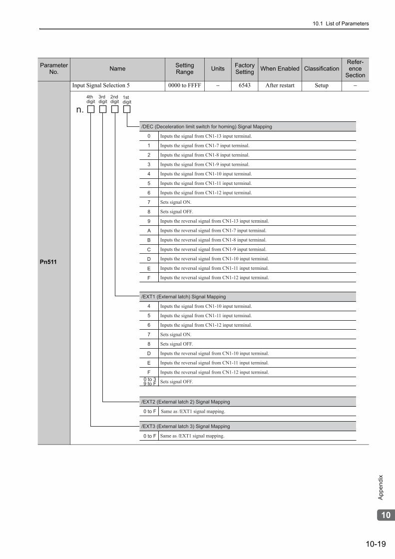
10.1 List of Parameters
10-19
10
Ap
pe
nd
ix
Pn511
Input Signal Selection 5 0000 to FFFF − 6543 After restart Setup −
Parameter No. Name Setting
Range Units Factory Setting When Enabled Classification
Refer-ence
Section
4thdigit
3rddigit
2nd digit
1stdigit
n.
Same as /EXT1 signal mapping.
/EXT2 (External latch 2) Signal Mapping
/DEC (Deceleration limit switch for homing) Signal Mapping
0
1
2
3
4
5
6
7
8
9
A
B
C
D
E
F
Inputs the signal from CN1-13 input terminal.
Inputs the signal from CN1-7 input terminal.
Inputs the signal from CN1-8 input terminal.
Inputs the signal from CN1-9 input terminal.
Inputs the signal from CN1-10 input terminal.
Inputs the signal from CN1-11 input terminal.
Inputs the signal from CN1-12 input terminal.
Sets signal ON.
Sets signal OFF.
Inputs the reversal signal from CN1-13 input terminal.
Inputs the reversal signal from CN1-7 input terminal.
Inputs the reversal signal from CN1-8 input terminal.
Inputs the reversal signal from CN1-9 input terminal.
Inputs the reversal signal from CN1-10 input terminal.
Inputs the reversal signal from CN1-11 input terminal.
Inputs the reversal signal from CN1-12 input terminal.
/EXT1 (External latch) Signal Mapping
4
5
6
7
8
D
E
F
Inputs the signal from CN1-10 input terminal.
Inputs the signal from CN1-11 input terminal.
Inputs the signal from CN1-12 input terminal.
Sets signal ON.
Sets signal OFF.
Inputs the reversal signal from CN1-10 input terminal.
Inputs the reversal signal from CN1-11 input terminal.
Inputs the reversal signal from CN1-12 input terminal.
Sets signal OFF.
Same as /EXT1 signal mapping.
/EXT3 (External latch 3) Signal Mapping
0 to 39 to F
0 to F
0 to F
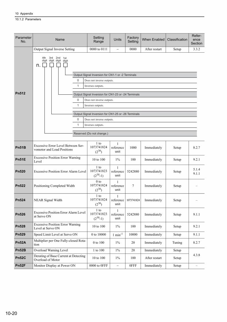
10 Appendix
10.1.2 Parameters
10-20
Pn512
Output Signal Inverse Setting 0000 to 0111 − 0000 After restart Setup 3.3.2
Pn51B Excessive Error Level Between Ser-vomotor and Load Positions
1 to 1073741824
(230)
1reference
unit1000 Immediately Setup 8.2.7
Pn51E Excessive Position Error Warning Level 10 to 100 1% 100 Immediately Setup 9.2.1
Pn520 Excessive Position Error Alarm Level1 to
1073741823(230-1)
1reference
unit5242880 Immediately Setup 5.1.4
9.1.1
Pn522 Positioning Completed Width0 to
1073741824(230)
1reference
unit7 Immediately Setup –
Pn524 NEAR Signal Width1 to
1073741824(230)
1reference
unit1073741824 Immediately Setup –
Pn526 Excessive Position Error Alarm Level at Servo ON
1 to 1073741823
(230-1)
1reference
unit5242880 Immediately Setup 9.1.1
Pn528 Excessive Position Error Warning Level at Servo ON 10 to 100 1% 100 Immediately Setup 9.2.1
Pn529 Speed Limit Level at Servo ON 0 to 10000 1 min-1 10000 Immediately Setup 9.1.1
Pn52A Multiplier per One Fully-closed Rota-tion 0 to 100 1% 20 Immediately Tuning 8.2.7
Pn52B Overload Warning Level 1 to 100 1% 20 Immediately Setup4.3.8
Pn52C Derating of Base Current at Detecting Overload of Motor 10 to 100 1% 100 After restart Setup
Pn52F Monitor Display at Power ON 0000 to 0FFF − 0FFF Immediately Setup –
Parameter No. Name Setting
Range Units Factory Setting When Enabled Classification
Refer-ence
Section
4th
digit
3rd
digit
2nd
digit1st
digit
n.
Output Signal Inversion for CN1-1 or -2 Terminals
0
1
Does not inverse outputs.
Inverses outputs.
Output Signal Inversion for CN1-23 or -24 Terminals
0
1
Does not inverse outputs.
Inverses outputs.
Output Signal Inversion for CN1-25 or -26 Terminals
0
1
Does not inverse outputs.
Inverses outputs.
Reserved (Do not change.)
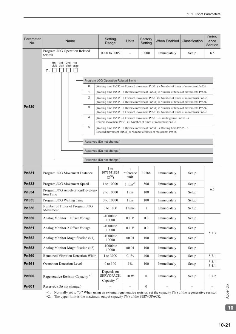
10.1 List of Parameters
10-21
10
Ap
pe
nd
ix
Pn530
Program JOG Operation Related Switch 0000 to 0005 − 0000 Immediately Setup 6.5
Pn531 Program JOG Movement Distance1 to
1073741824(230)
1reference
unit32768 Immediately Setup
6.5Pn533 Program JOG Movement Speed 1 to 10000 1 min-1 500 Immediately Setup
Pn534 Program JOG Acceleration/Decelera-tion Time 2 to 10000 1 ms 100 Immediately Setup
Pn535 Program JOG Waiting Time 0 to 10000 1 ms 100 Immediately Setup
Pn536 Number of Times of Program JOG Movement 0 to 1000 1 time 1 Immediately Setup
Pn550 Analog Monitor 1 Offset Voltage -10000 to 10000 0.1 V 0.0 Immediately Setup
5.1.3Pn551 Analog Monitor 2 Offset Voltage -10000 to
10000 0.1 V 0.0 Immediately Setup
Pn552 Analog Monitor Magnification (×1) -10000 to 10000 ×0.01 100 Immediately Setup
Pn553 Analog Monitor Magnification (×2) -10000 to 10000 ×0.01 100 Immediately Setup
Pn560 Remained Vibration Detection Width 1 to 3000 0.1% 400 Immediately Setup 5.7.1
Pn561 Overshoot Detection Level 0 to 100 1% 100 Immediately Setup 5.3.15.4.1
Pn600 Regenerative Resistor Capacity ∗1Depends on
SERVOPACKCapacity ∗2
10 W 0 Immediately Setup 3.7.2
Pn601 Reserved (Do not change.) – – 0 – – –
∗1. Normally set to "0." When using an external regenerative resistor, set the capacity (W) of the regenerative resistor.∗2. The upper limit is the maximum output capacity (W) of the SERVOPACK.
Parameter No. Name Setting
Range Units Factory Setting When Enabled Classification
Refer-ence
Section
4th
digit
3rd
digit
2nd
digit1st
digit
n.
Program JOG Operation Related Switch
0
1
2
3
4
5
Reserved (Do not change.)
(Waiting time Pn535 → Forward movement Pn531) × Number of times of movement Pn536
(Waiting time Pn535 → Reverse movement Pn531) × Number of times of movements Pn536
(Waiting time Pn535 → Forward movement Pn531) × Number of times of movements Pn536(Waiting time Pn535 → Reverse movement Pn531) × Number of times of movements Pn536
(Waiting time Pn535 → Reverse movement Pn531) × Number of times of movements Pn536(Waiting time Pn535 → Forward movement Pn531) × Number of times of movements Pn536
(Waiting time Pn535 → Forward movement Pn531 → Waiting time Pn535 → Reverse movement Pn531) × Number of times of movement Pn536
(Waiting time Pn535 → Reverse movement Pn531 → Waiting time Pn535 → Forward movement Pn531) × Number of times of movement Pn536
Reserved (Do not change.)
Reserved (Do not change.)
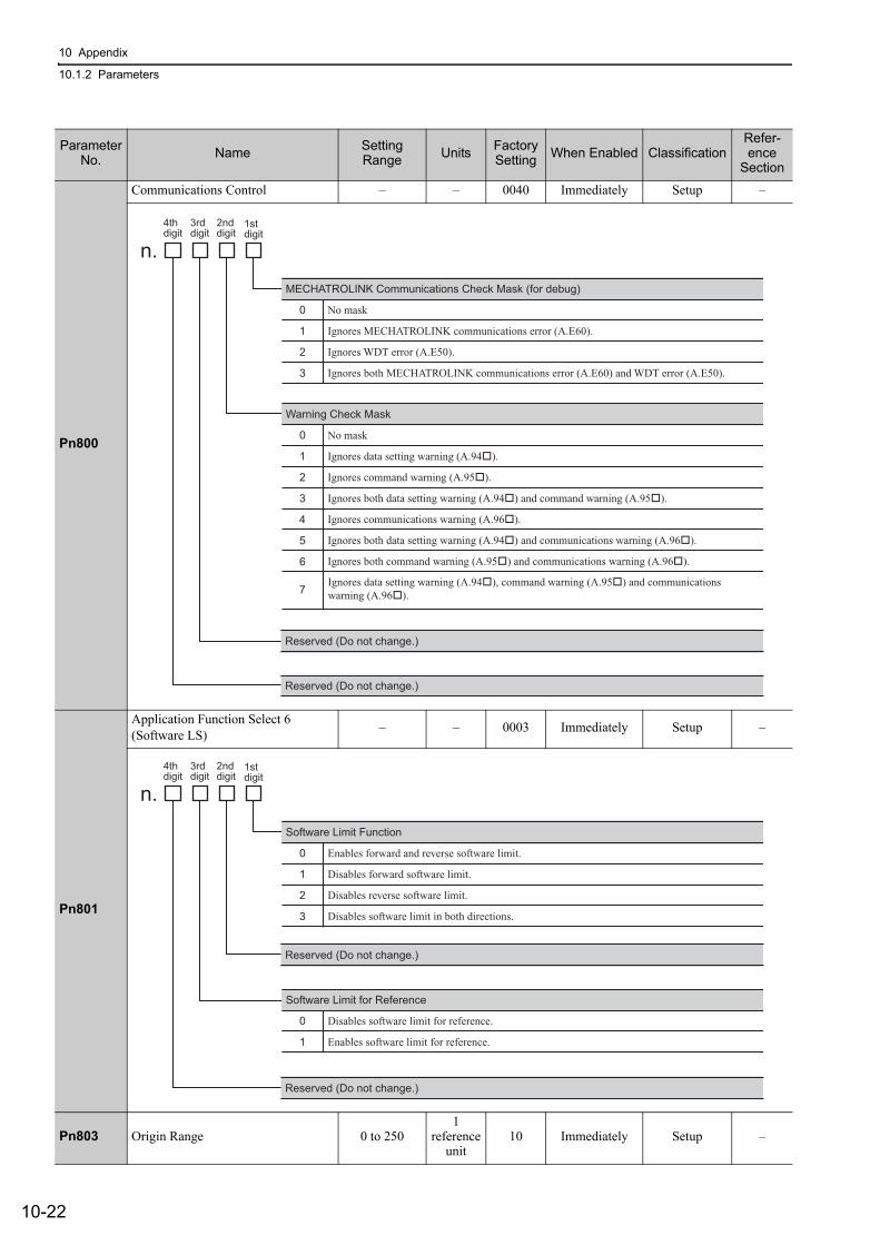
10 Appendix
10.1.2 Parameters
10-22
Pn800
Communications Control – – 0040 Immediately Setup –
Pn801
Application Function Select 6(Software LS) – – 0003 Immediately Setup –
Pn803 Origin Range 0 to 2501
reference unit
10 Immediately Setup –
Parameter No. Name Setting
Range Units Factory Setting When Enabled Classification
Refer-ence
Section
4th
digit
3rd
digit
2nd
digit1st
digit
n.
MECHATROLINK Communications Check Mask (for debug)
0
1
2
3
No mask
Ignores MECHATROLINK communications error (A.E60).
Ignores WDT error (A.E50).
Ignores both MECHATROLINK communications error (A.E60) and WDT error (A.E50).
Warning Check Mask
0
1
2
3
4
5
6
7
No mask
Ignores data setting warning (A.94�).
Ignores command warning (A.95�).
Ignores both data setting warning (A.94�) and command warning (A.95�).
Ignores communications warning (A.96�).
Ignores both data setting warning (A.94�) and communications warning (A.96�).
Ignores both command warning (A.95�) and communications warning (A.96�).
Reserved (Do not change.)
Reserved (Do not change.)
Ignores data setting warning (A.94�), command warning (A.95�) and communicationswarning (A.96�).
4th
digit
3rd
digit
2nd
digit1st
digit
n.
Software Limit Function
0
1
2
3
Enables forward and reverse software limit.
Disables forward software limit.
Disables reverse software limit.
Disables software limit in both directions.
Software Limit for Reference
0
1
Disables software limit for reference.
Enables software limit for reference.
Reserved (Do not change.)
Reserved (Do not change.)
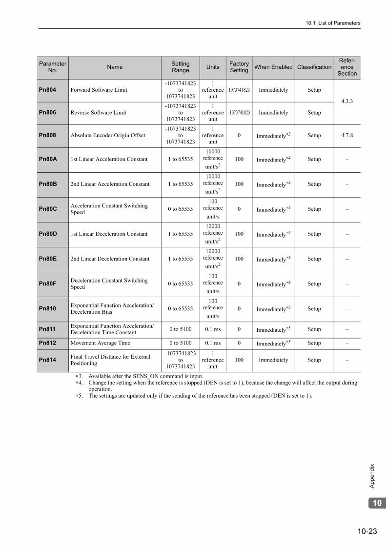
10.1 List of Parameters
10-23
10
Ap
pe
nd
ix
Pn804 Forward Software Limit-1073741823
to1073741823
1reference
unit1073741823 Immediately Setup
4.3.3
Pn806 Reverse Software Limit -1073741823
to 1073741823
1reference
unit-1073741823 Immediately Setup
Pn808 Absolute Encoder Origin Offset-1073741823
to 1073741823
1reference
unit0 Immediately∗3 Setup 4.7.8
Pn80A 1st Linear Acceleration Constant 1 to 6553510000
referenceunit/s2
100 Immediately∗4 Setup –
Pn80B 2nd Linear Acceleration Constant 1 to 6553510000
referenceunit/s2
100 Immediately∗4 Setup –
Pn80C Acceleration Constant Switching Speed 0 to 65535
100reference
unit/s0 Immediately∗4 Setup –
Pn80D 1st Linear Deceleration Constant 1 to 6553510000
referenceunit/s2
100 Immediately∗4 Setup –
Pn80E 2nd Linear Deceleration Constant 1 to 6553510000
referenceunit/s2
100 Immediately∗4 Setup –
Pn80F Deceleration Constant Switching Speed 0 to 65535
100reference
unit/s0 Immediately∗4 Setup –
Pn810 Exponential Function Acceleration/Deceleration Bias 0 to 65535
100reference
unit/s0 Immediately∗5 Setup –
Pn811 Exponential Function Acceleration/Deceleration Time Constant 0 to 5100 0.1 ms 0 Immediately∗5 Setup –
Pn812 Movement Average Time 0 to 5100 0.1 ms 0 Immediately∗5 Setup –
Pn814 Final Travel Distance for External Positioning
-1073741823 to
1073741823
1reference
unit100 Immediately Setup –
∗3. Available after the SENS_ON command is input.∗4. Change the setting when the reference is stopped (DEN is set to 1), because the change will affect the output during
operation.∗5. The settings are updated only if the sending of the reference has been stopped (DEN is set to 1).
Parameter No. Name Setting
Range Units Factory Setting When Enabled Classification
Refer-ence
Section
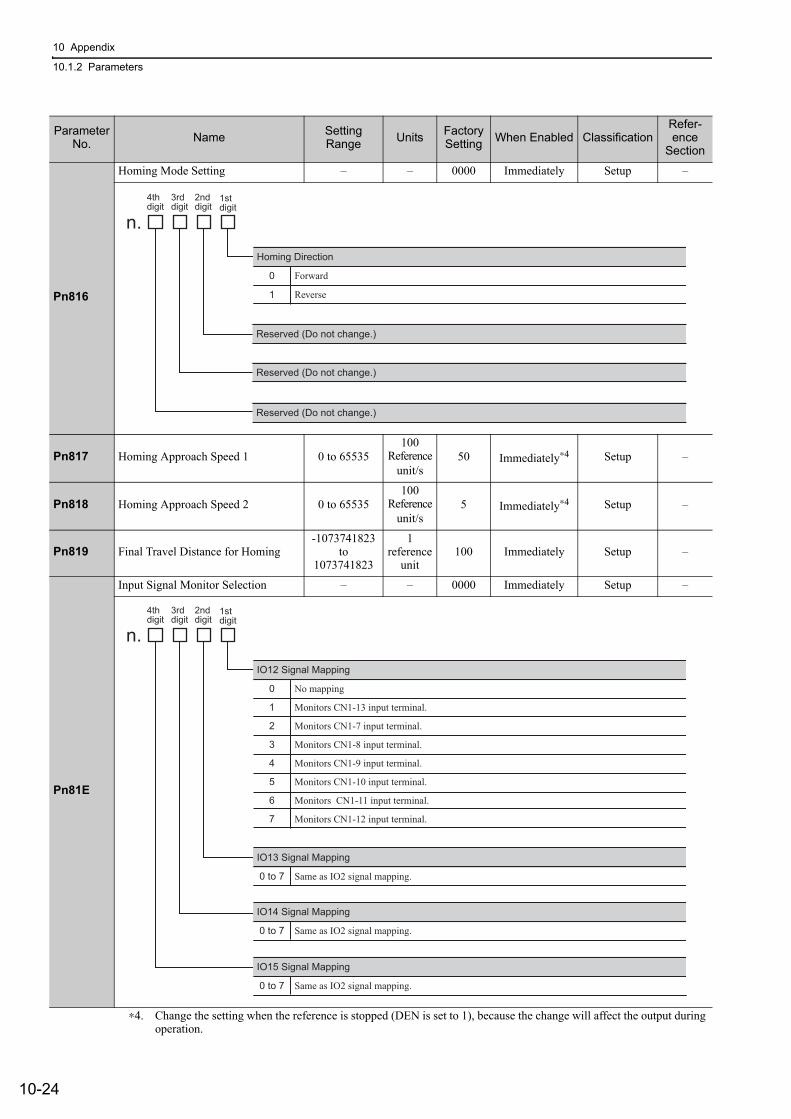
10 Appendix
10.1.2 Parameters
10-24
Pn816
Homing Mode Setting – – 0000 Immediately Setup –
Pn817 Homing Approach Speed 1 0 to 65535100
Referenceunit/s
50 Immediately∗4 Setup –
Pn818 Homing Approach Speed 2 0 to 65535100
Referenceunit/s
5 Immediately∗4 Setup –
Pn819 Final Travel Distance for Homing-1073741823
to 1073741823
1reference
unit100 Immediately Setup –
Pn81E
Input Signal Monitor Selection – – 0000 Immediately Setup –
∗4. Change the setting when the reference is stopped (DEN is set to 1), because the change will affect the output during operation.
Parameter No. Name Setting
Range Units Factory Setting When Enabled Classification
Refer-ence
Section
4th
digit
3rd
digit
2nd
digit1st
digit
n.
Homing Direction
0
1
Forward
Reverse
Reserved (Do not change.)
Reserved (Do not change.)
Reserved (Do not change.)
4thdigit
3rddigit
2nd digit
1stdigit
n.
IO12 Signal Mapping
0
1
2
3
4
5
6
7
No mapping
Monitors CN1-13 input terminal.
Monitors CN1-7 input terminal.
Monitors CN1-8 input terminal.
Monitors CN1-9 input terminal.
Monitors CN1-10 input terminal.
Monitors CN1-11 input terminal.
Monitors CN1-12 input terminal.
IO13 Signal Mapping
0 to 7 Same as IO2 signal mapping.
IO14 Signal Mapping
0 to 7 Same as IO2 signal mapping.
IO15 Signal Mapping
0 to 7 Same as IO2 signal mapping.
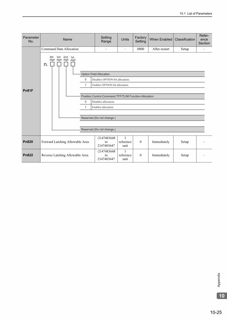
10.1 List of Parameters
10-25
10
Ap
pe
nd
ix
Pn81F
Command Data Allocation – – 0000 After restart Setup –
Pn820 Forward Latching Allowable Area-2147483648
to 2147483647
1reference
unit0 Immediately Setup –
Pn822 Reverse Latching Allowable Area-2147483648
to 2147483647
1reference
unit0 Immediately Setup –
Parameter No. Name Setting
Range Units Factory Setting When Enabled Classification
Refer-ence
Section
4th
digit
3rd
digit
2nd
digit1st
digit
n.
Option Field Allocation
0
1
Disables OPTION bit allocation.
Enables OPTION bit allocation.
Position Control Command TFF/TLIM Function Allocation
0
1
Disables allocation.
Enables allocation.
Reserved (Do not change.)
Reserved (Do not change.)
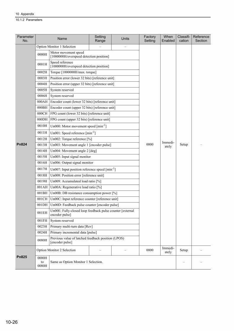
10 Appendix
10.1.2 Parameters
10-26
Parameter No. Name Setting
Range Units Factory Setting
When Enabled
Classifi-cation
Reference Section
Pn824
Option Monitor 1 Selection – –
0000 Immedi-ately Setup –
0000H Motor movement speed [1000000H/overspeed detection position]
0001H Speed reference [1000000H/overspeed detection position]
0002H Torque [1000000H/max. torque]
0003H Position error (lower 32 bits) [reference unit]
0004H Position error (upper 32 bits) [reference unit]
0005H System reserved
0006H System reserved
000AH Encoder count (lower 32 bits) [reference unit]
000BH Encoder count (upper 32 bits) [reference unit]
000CH FPG count (lower 32 bits) [reference unit]
000DH FPG count (upper 32 bits) [reference unit]
0010H Un000: Motor movement speed [min-1]
0011H Un001: Speed reference [min-1]
0012H Un002: Torque reference [%]
0013H Un003: Movement angle 1 [encoder pulse]
0014H Un004: Movement angle 2 [deg]
0015H Un005: Input signal monitor
0016H Un006: Output signal monitor
0017H Un007: Input position reference speed [min-1]
0018H Un008: Position error [reference unit]
0019H Un009: Accumulated load ratio [%]
001AH Un00A: Regenerative load ratio [%]
001BH Un00B: DB resistance consumption power [%]
001CH Un00C: Input reference counter [reference unit]
001DH Un00D: Feedback pulse counter [encoder pulse]
001EH Un00E: Fully-closed loop feedback pulse counter [external encoder pulse]
001FH System reserved
0023H Primary multi-turn data [Rev]
0024H Primary incremental data [pulse]
0080H Previous value of latched feedback position (LPOS) [encoder pulse]
Pn825
Option Monitor 2 Selection – – 0000 Immedi-ately Setup –
0000Hto
0080HSame as Option Monitor 1 Selection. – –
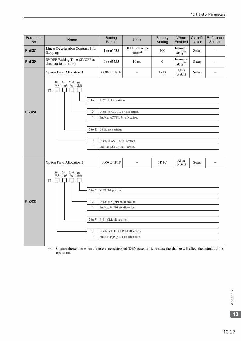
10.1 List of Parameters
10-27
10
Ap
pe
nd
ix
Pn827 Linear Deceleration Constant 1 for Stopping 1 to 65535
10000 reference unit/s2 100
Immedi-ately∗4 Setup –
Pn829 SVOFF Waiting Time (SVOFF at deceleration to stop) 0 to 65535 10 ms 0
Immedi-ately∗4 Setup –
Pn82A
Option Field Allocation 1 0000 to 1E1E – 1813 After restart Setup –
Pn82B
Option Field Allocation 2 0000 to 1F1F – 1D1C After restart Setup –
∗4. Change the setting when the reference is stopped (DEN is set to 1), because the change will affect the output during operation.
Parameter No. Name Setting
Range Units Factory Setting
When Enabled
Classifi-cation
Reference Section
4th
digit
3rd
digit
2nd
digit1st
digit
n.
0 to E ACCFIL bit position
0
1
Disables ACCFIL bit allocation.
Enables ACCFIL bit allocation.
0 to E GSEL bit position
0
1
Disables GSEL bit allocation.
Enables GSEL bit allocation.
4thdigit
3rddigit
2nd digit
1stdigit
n.0 to F V_PPI bit position
0
1
Disables V_PPI bit allocation.
Enables V_PPI bit allocation.
0 to F P_PI_CLR bit position
0
1
Disables P_PI_CLR bit allocation.
Enables P_PI_CLR bit allocation.
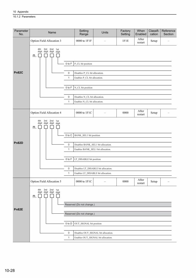
10 Appendix
10.1.2 Parameters
10-28
Pn82C
Option Field Allocation 3 0000 to 1F1F – 1F1E After restart Setup –
Pn82D
Option Field Allocation 4 0000 to 1F1C – 0000 After restart Setup –
Pn82E
Option Field Allocation 5 0000 to 1F1C – 0000 After restart Setup –
Parameter No. Name Setting
Range Units Factory Setting
When Enabled
Classifi-cation
Reference Section
4th
digit
3rd
digit
2nd
digit1st
digit
n.
0 to F P_CL bit position
0
1
Disables P_CL bit allocation.
Enables P_CL bit allocation.
0 to F N_CL bit position
0
1
Disables N_CL bit allocation.
Enables N_CL bit allocation.
4th
digit
3rd
digit
2nd
digit1st
digit
n.
0 to C BANK_SEL1 bit position
0
1
Disables BANK_SEL1 bit allocation.
Enables BANK_SEL1 bit allocation.
0 to F LT_DISABLE bit position
0
1
Disables LT_DISABLE bit allocation.
Enables LT_DISABLE bit allocation.
4th
digit
3rd
digit
2nd
digit1st
digit
n.
0 to D OUT_SIGNAL bit position
0
1
Disables OUT_SIGNAL bit allocation.
Enables OUT_SIGNAL bit allocation.
Reserved (Do not change.)
Reserved (Do not change.)
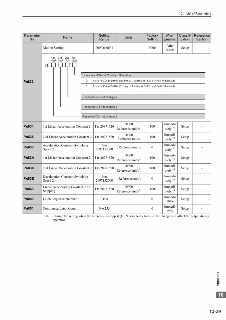
10.1 List of Parameters
10-29
10
Ap
pe
nd
ix
Pn833
Motion Setting 0000 to 0001 – 0000 After restart Setup –
Pn834 1st Linear Acceleration Constant 2 1 to 2097152010000
Reference unit/s2 100Immedi-ately ∗4 Setup –
Pn836 2nd Linear Acceleration Constant 2 1 to 20971520 10000Reference unit/s 100
Immedi-ately ∗4 Setup –
Pn838 Acceleration Constant Switching Speed 2
0 to 2097152000 1 Reference unit/s 0
Immedi-ately ∗4 Setup –
Pn83A 1st Linear Deceleration Constant 2 1 to 2097152010000
Reference unit/s2 100Immedi-ately ∗4 Setup –
Pn83C 2nd Linear Deceleration Constant 2 1 to 2097152010000
Reference unit/s2 100Immedi-ately ∗4 Setup –
Pn83E Deceleration Constant Switching Speed 2
0 to 2097152000 1 Reference unit/s 0
Immedi-ately ∗4 Setup –
Pn840 Linear Deceleration Constant 2 for Stopping 1 to 20971520
10000Reference unit/s2 100
Immedi-ately ∗4 Setup –
Pn850 Latch Sequence Number 0 to 8 – 0 Immedi-ately Setup –
Pn851 Continuous Latch Count 0 to 255 – 0 Immedi-ately Setup –
∗4. Change the setting when the reference is stopped (DEN is set to 1), because the change will affect the output during operation.
Parameter No. Name Setting
Range Units Factory Setting
When Enabled
Classifi-cation
Reference Section
4th
digit
3rd
digit
2nd
digit1st
digit
n.
Linear Accel/Decel Constant Selection
0
1
Uses Pn80A to Pn80F and Pn827. (Setting of Pn834 to Pn840 disabled)
Uses Pn834 to Pn840. (Setting of Pn80A to Pn80F and Pn827 disabled)
Reserved (Do not change.)
Reserved (Do not change.)
Reserved (Do not change.)
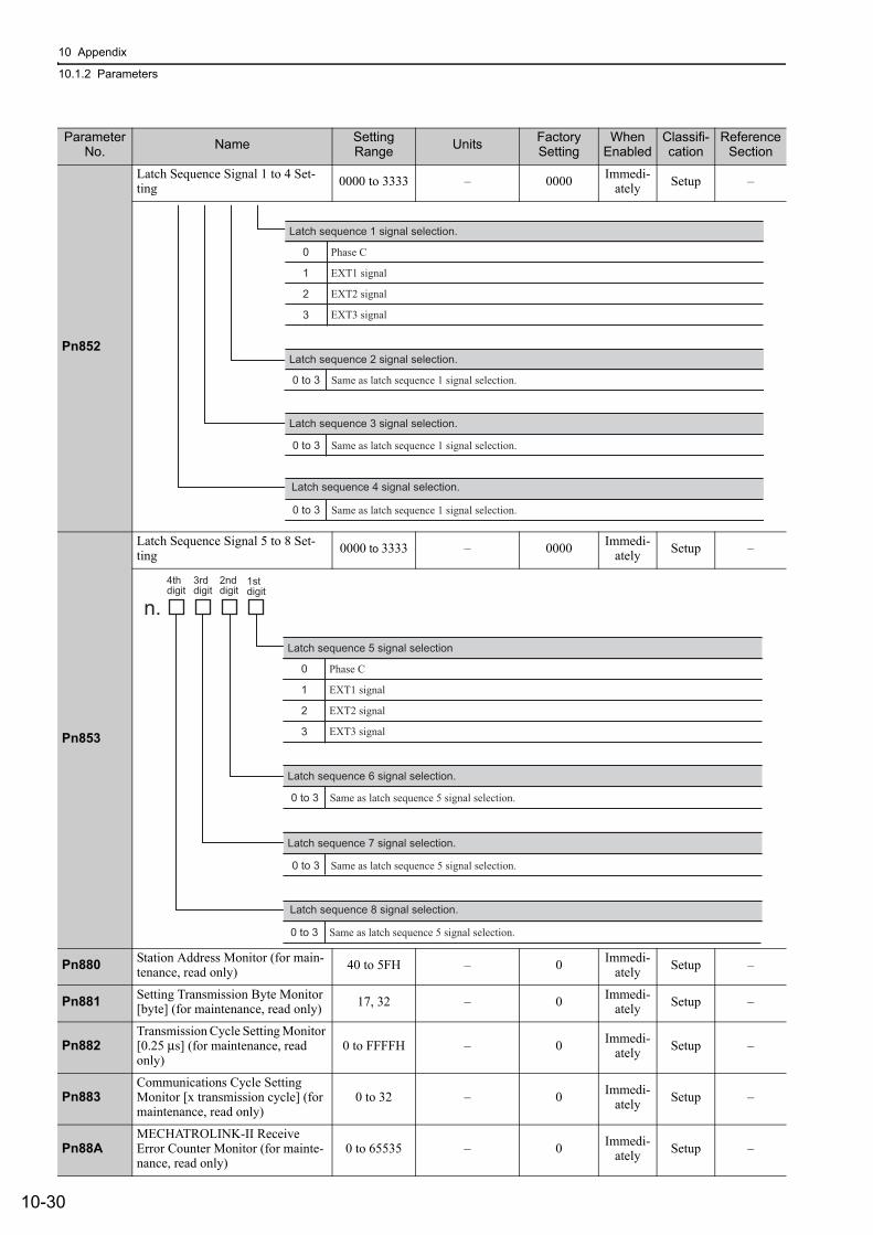
10 Appendix
10.1.2 Parameters
10-30
Pn852
Latch Sequence Signal 1 to 4 Set-ting 0000 to 3333 – 0000 Immedi-
ately Setup –
Pn853
Latch Sequence Signal 5 to 8 Set-ting 0000 to 3333 – 0000 Immedi-
ately Setup –
Pn880 Station Address Monitor (for main-tenance, read only) 40 to 5FH – 0 Immedi-
ately Setup –
Pn881 Setting Transmission Byte Monitor [byte] (for maintenance, read only) 17, 32 – 0 Immedi-
ately Setup –
Pn882Transmission Cycle Setting Monitor [0.25 μs] (for maintenance, read only)
0 to FFFFH – 0 Immedi-ately Setup –
Pn883Communications Cycle Setting Monitor [x transmission cycle] (for maintenance, read only)
0 to 32 – 0 Immedi-ately Setup –
Pn88AMECHATROLINK-II Receive Error Counter Monitor (for mainte-nance, read only)
0 to 65535 – 0 Immedi-ately Setup –
Parameter No. Name Setting
Range Units Factory Setting
When Enabled
Classifi-cation
Reference Section
Latch sequence 1 signal selection.
0
1
2
3
Phase C
EXT1 signal
EXT2 signal
EXT3 signal
Latch sequence 2 signal selection.
Latch sequence 3 signal selection.
Latch sequence 4 signal selection.
0 to 3 Same as latch sequence 1 signal selection.
0 to 3 Same as latch sequence 1 signal selection.
0 to 3 Same as latch sequence 1 signal selection.
4thdigit
3rddigit
2nd digit
1stdigit
n.
Latch sequence 5 signal selection
0
1
2
3
Phase C
EXT1 signal
EXT2 signal
EXT3 signal
Latch sequence 6 signal selection.
Latch sequence 7 signal selection.
Latch sequence 8 signal selection.
0 to 3 Same as latch sequence 5 signal selection.
0 to 3 Same as latch sequence 5 signal selection.
0 to 3 Same as latch sequence 5 signal selection.
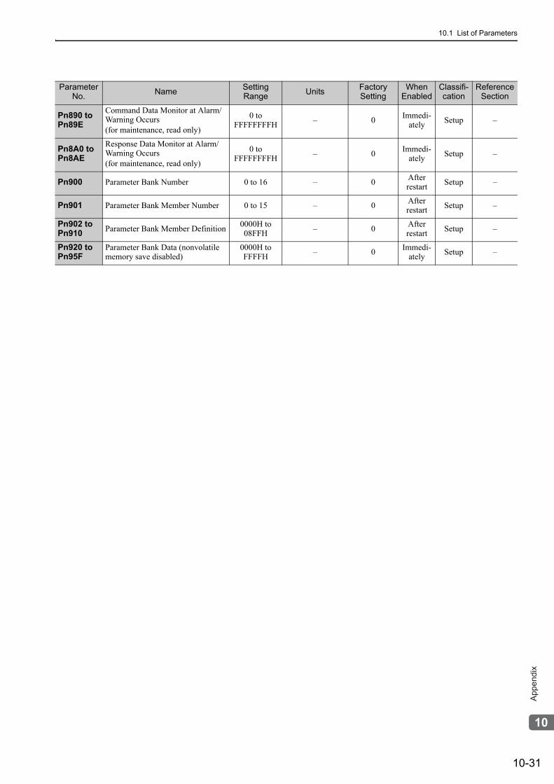
10.1 List of Parameters
10-31
10
Ap
pe
nd
ix
Pn890 to Pn89E
Command Data Monitor at Alarm/Warning Occurs(for maintenance, read only)
0 to FFFFFFFFH – 0 Immedi-
ately Setup –
Pn8A0 to Pn8AE
Response Data Monitor at Alarm/Warning Occurs(for maintenance, read only)
0 to FFFFFFFFH – 0 Immedi-
ately Setup –
Pn900 Parameter Bank Number 0 to 16 – 0 After restart Setup –
Pn901 Parameter Bank Member Number 0 to 15 – 0 After restart Setup –
Pn902 to Pn910 Parameter Bank Member Definition 0000H to
08FFH – 0 After restart Setup –
Pn920 to Pn95F
Parameter Bank Data (nonvolatile memory save disabled)
0000H to FFFFH – 0 Immedi-
ately Setup –
Parameter No. Name Setting
Range Units Factory Setting
When Enabled
Classifi-cation
Reference Section
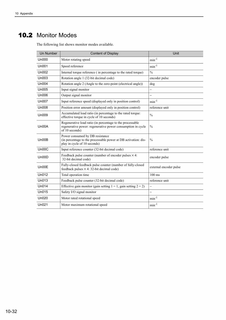
10 Appendix
10-32
10.2 Monitor ModesThe following list shows monitor modes available.
Un Number Content of Display Unit
Un000 Motor rotating speed min-1
Un001 Speed reference min-1
Un002 Internal torque reference ( in percentage to the rated torque) %
Un003 Rotation angle 1 (32-bit decimal code) encoder pulse
Un004 Rotation angle 2 (Angle to the zero-point (electrical angle)) deg
Un005 Input signal monitor −
Un006 Output signal monitor −
Un007 Input reference speed (displayed only in position control) min-1
Un008 Position error amount (displayed only in position control) reference unit
Un009 Accumulated load ratio (in percentage to the rated torque: effective torque in cycle of 10 seconds) %
Un00ARegenerative load ratio (in percentage to the processable regenerative power: regenerative power consumption in cycle of 10 seconds)
%
Un00BPower consumed by DB resistance(in percentage to the processable power at DB activation: dis-play in cycle of 10 seconds)
%
Un00C Input reference counter (32-bit decimal code) reference unit
Un00D Feedback pulse counter (number of encoder pulses × 4: 32-bit decimal code) encoder pulse
Un00E Fully-closed feedback pulse counter (number of fully-closed feedback pulses × 4: 32-bit decimal code) external encoder pulse
Un012 Total operation time 100 ms
Un013 Feedback pulse counter (32-bit decimal code) reference unit
Un014 Effective gain monitor (gain setting 1 = 1, gain setting 2 = 2) −
Un015 Safety I/O signal monitor −
Un020 Motor rated rotational speed min-1
Un021 Motor maximum rotational speed min-1
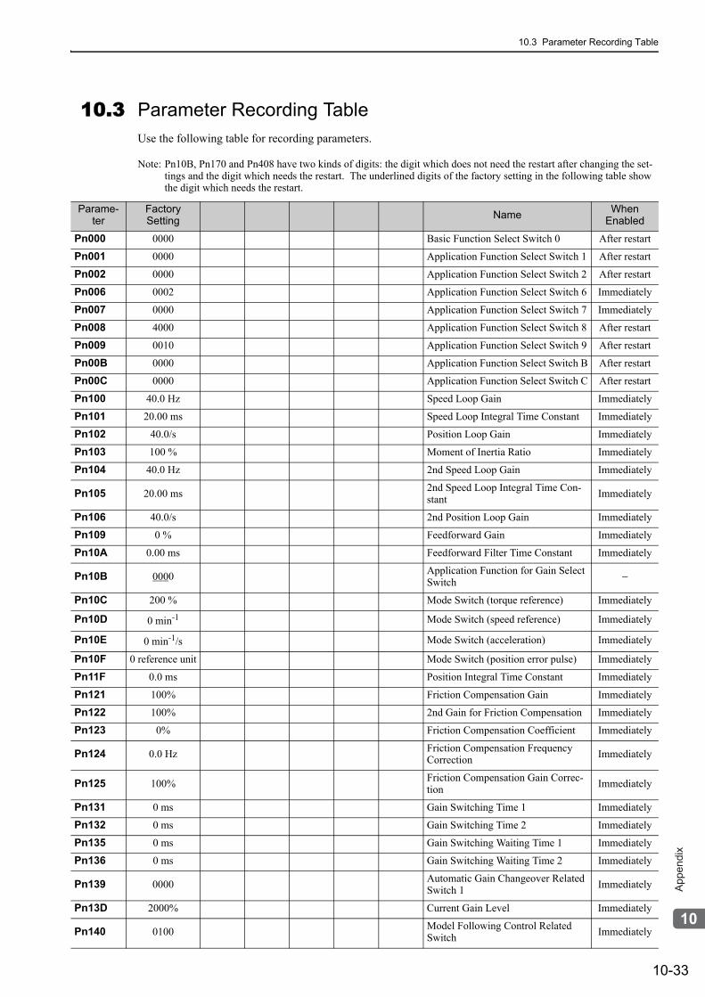
10.3 Parameter Recording Table
10-33
10
Ap
pe
nd
ix
10.3 Parameter Recording TableUse the following table for recording parameters.
Note: Pn10B, Pn170 and Pn408 have two kinds of digits: the digit which does not need the restart after changing the set-tings and the digit which needs the restart. The underlined digits of the factory setting in the following table show the digit which needs the restart.
Parame-ter
Factory Setting Name When
Enabled
Pn000 0000 Basic Function Select Switch 0 After restart
Pn001 0000 Application Function Select Switch 1 After restart
Pn002 0000 Application Function Select Switch 2 After restart
Pn006 0002 Application Function Select Switch 6 Immediately
Pn007 0000 Application Function Select Switch 7 Immediately
Pn008 4000 Application Function Select Switch 8 After restart
Pn009 0010 Application Function Select Switch 9 After restart
Pn00B 0000 Application Function Select Switch B After restart
Pn00C 0000 Application Function Select Switch C After restart
Pn100 40.0 Hz Speed Loop Gain Immediately
Pn101 20.00 ms Speed Loop Integral Time Constant Immediately
Pn102 40.0/s Position Loop Gain Immediately
Pn103 100 % Moment of Inertia Ratio Immediately
Pn104 40.0 Hz 2nd Speed Loop Gain Immediately
Pn105 20.00 ms 2nd Speed Loop Integral Time Con-stant Immediately
Pn106 40.0/s 2nd Position Loop Gain Immediately
Pn109 0 % Feedforward Gain Immediately
Pn10A 0.00 ms Feedforward Filter Time Constant Immediately
Pn10B 0000 Application Function for Gain Select Switch −
Pn10C 200 % Mode Switch (torque reference) Immediately
Pn10D 0 min-1 Mode Switch (speed reference) Immediately
Pn10E 0 min-1/s Mode Switch (acceleration) Immediately
Pn10F 0 reference unit Mode Switch (position error pulse) Immediately
Pn11F 0.0 ms Position Integral Time Constant Immediately
Pn121 100% Friction Compensation Gain Immediately
Pn122 100% 2nd Gain for Friction Compensation Immediately
Pn123 0% Friction Compensation Coefficient Immediately
Pn124 0.0 Hz Friction Compensation Frequency Correction Immediately
Pn125 100% Friction Compensation Gain Correc-tion Immediately
Pn131 0 ms Gain Switching Time 1 Immediately
Pn132 0 ms Gain Switching Time 2 Immediately
Pn135 0 ms Gain Switching Waiting Time 1 Immediately
Pn136 0 ms Gain Switching Waiting Time 2 Immediately
Pn139 0000 Automatic Gain Changeover Related Switch 1 Immediately
Pn13D 2000% Current Gain Level Immediately
Pn140 0100 Model Following Control Related Switch Immediately
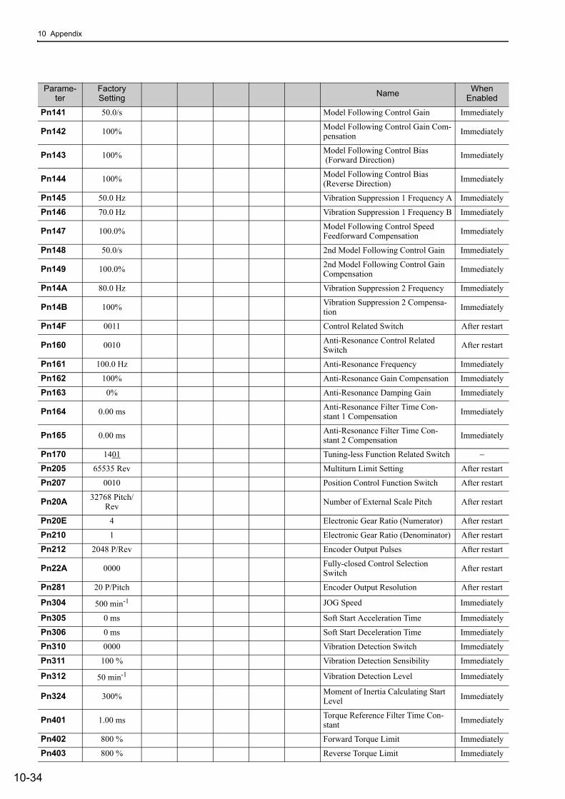
10 Appendix
10-34
Pn141 50.0/s Model Following Control Gain Immediately
Pn142 100% Model Following Control Gain Com-pensation Immediately
Pn143 100% Model Following Control Bias (Forward Direction) Immediately
Pn144 100% Model Following Control Bias(Reverse Direction) Immediately
Pn145 50.0 Hz Vibration Suppression 1 Frequency A Immediately
Pn146 70.0 Hz Vibration Suppression 1 Frequency B Immediately
Pn147 100.0% Model Following Control Speed Feedforward Compensation Immediately
Pn148 50.0/s 2nd Model Following Control Gain Immediately
Pn149 100.0% 2nd Model Following Control Gain Compensation Immediately
Pn14A 80.0 Hz Vibration Suppression 2 Frequency Immediately
Pn14B 100% Vibration Suppression 2 Compensa-tion Immediately
Pn14F 0011 Control Related Switch After restart
Pn160 0010 Anti-Resonance Control Related Switch After restart
Pn161 100.0 Hz Anti-Resonance Frequency Immediately
Pn162 100% Anti-Resonance Gain Compensation Immediately
Pn163 0% Anti-Resonance Damping Gain Immediately
Pn164 0.00 ms Anti-Resonance Filter Time Con-stant 1 Compensation Immediately
Pn165 0.00 ms Anti-Resonance Filter Time Con-stant 2 Compensation Immediately
Pn170 1401 Tuning-less Function Related Switch −
Pn205 65535 Rev Multiturn Limit Setting After restart
Pn207 0010 Position Control Function Switch After restart
Pn20A 32768 Pitch/Rev Number of External Scale Pitch After restart
Pn20E 4 Electronic Gear Ratio (Numerator) After restart
Pn210 1 Electronic Gear Ratio (Denominator) After restart
Pn212 2048 P/Rev Encoder Output Pulses After restart
Pn22A 0000 Fully-closed Control Selection Switch After restart
Pn281 20 P/Pitch Encoder Output Resolution After restart
Pn304 500 min-1 JOG Speed Immediately
Pn305 0 ms Soft Start Acceleration Time Immediately
Pn306 0 ms Soft Start Deceleration Time Immediately
Pn310 0000 Vibration Detection Switch Immediately
Pn311 100 % Vibration Detection Sensibility Immediately
Pn312 50 min-1 Vibration Detection Level Immediately
Pn324 300% Moment of Inertia Calculating Start Level Immediately
Pn401 1.00 ms Torque Reference Filter Time Con-stant Immediately
Pn402 800 % Forward Torque Limit Immediately
Pn403 800 % Reverse Torque Limit Immediately
Parame-ter
Factory Setting Name When
Enabled
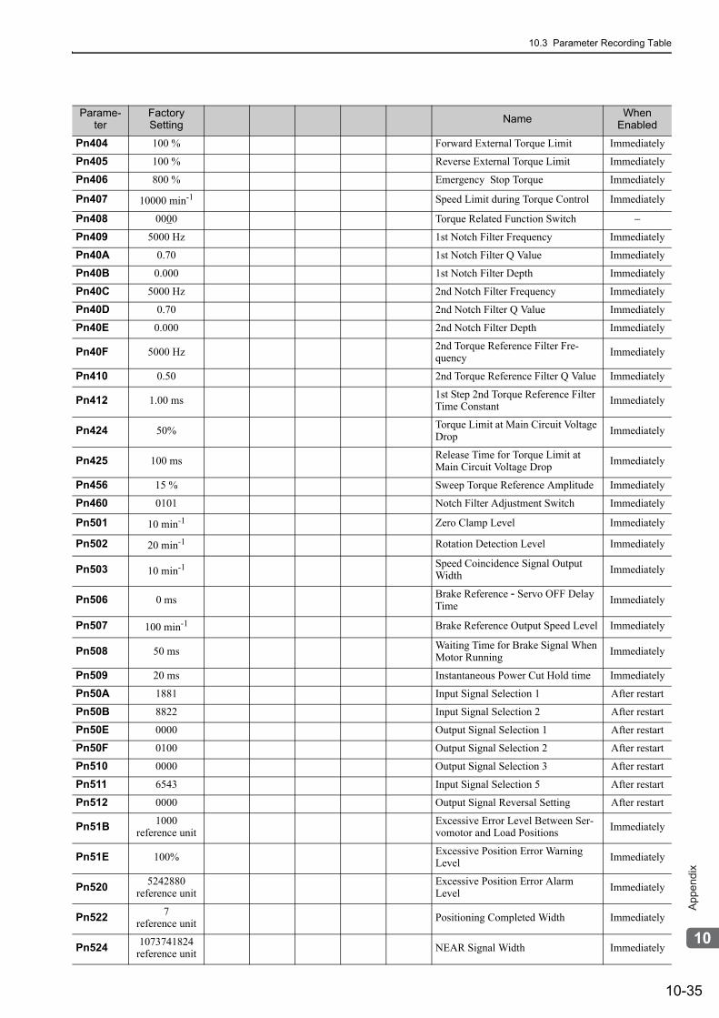
10.3 Parameter Recording Table
10-35
10
Ap
pe
nd
ix
Pn404 100 % Forward External Torque Limit Immediately
Pn405 100 % Reverse External Torque Limit Immediately
Pn406 800 % Emergency Stop Torque Immediately
Pn407 10000 min-1 Speed Limit during Torque Control Immediately
Pn408 0000 Torque Related Function Switch −
Pn409 5000 Hz 1st Notch Filter Frequency Immediately
Pn40A 0.70 1st Notch Filter Q Value Immediately
Pn40B 0.000 1st Notch Filter Depth Immediately
Pn40C 5000 Hz 2nd Notch Filter Frequency Immediately
Pn40D 0.70 2nd Notch Filter Q Value Immediately
Pn40E 0.000 2nd Notch Filter Depth Immediately
Pn40F 5000 Hz 2nd Torque Reference Filter Fre-quency Immediately
Pn410 0.50 2nd Torque Reference Filter Q Value Immediately
Pn412 1.00 ms 1st Step 2nd Torque Reference Filter Time Constant Immediately
Pn424 50% Torque Limit at Main Circuit Voltage Drop Immediately
Pn425 100 ms Release Time for Torque Limit at Main Circuit Voltage Drop Immediately
Pn456 15 % Sweep Torque Reference Amplitude Immediately
Pn460 0101 Notch Filter Adjustment Switch Immediately
Pn501 10 min-1 Zero Clamp Level Immediately
Pn502 20 min-1 Rotation Detection Level Immediately
Pn503 10 min-1 Speed Coincidence Signal Output Width Immediately
Pn506 0 ms Brake Reference - Servo OFF Delay Time Immediately
Pn507 100 min-1 Brake Reference Output Speed Level Immediately
Pn508 50 ms Waiting Time for Brake Signal When Motor Running Immediately
Pn509 20 ms Instantaneous Power Cut Hold time Immediately
Pn50A 1881 Input Signal Selection 1 After restart
Pn50B 8822 Input Signal Selection 2 After restart
Pn50E 0000 Output Signal Selection 1 After restart
Pn50F 0100 Output Signal Selection 2 After restart
Pn510 0000 Output Signal Selection 3 After restart
Pn511 6543 Input Signal Selection 5 After restart
Pn512 0000 Output Signal Reversal Setting After restart
Pn51B 1000 reference unit
Excessive Error Level Between Ser-vomotor and Load Positions Immediately
Pn51E 100% Excessive Position Error Warning Level Immediately
Pn520 5242880 reference unit
Excessive Position Error Alarm Level Immediately
Pn522 7 reference unit Positioning Completed Width Immediately
Pn524 1073741824 reference unit NEAR Signal Width Immediately
Parame-ter
Factory Setting Name When
Enabled
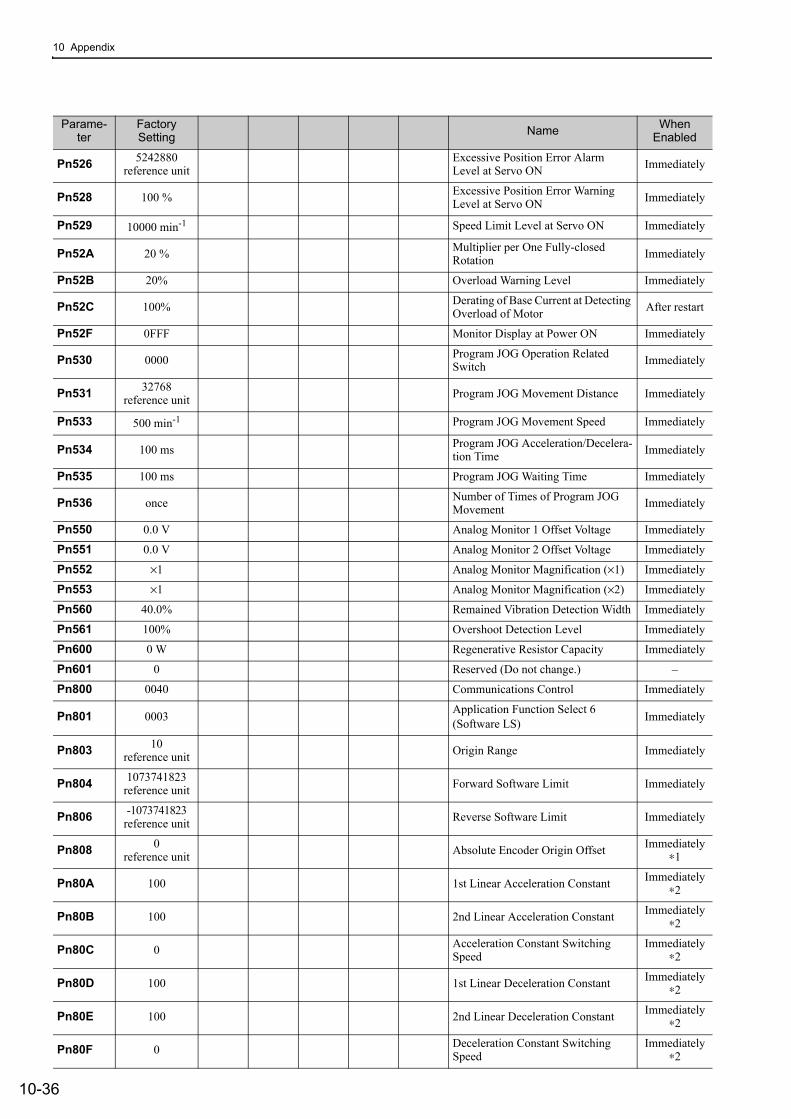
10 Appendix
10-36
Pn526 5242880 reference unit
Excessive Position Error Alarm Level at Servo ON Immediately
Pn528 100 % Excessive Position Error Warning Level at Servo ON Immediately
Pn529 10000 min-1 Speed Limit Level at Servo ON Immediately
Pn52A 20 % Multiplier per One Fully-closed Rotation Immediately
Pn52B 20% Overload Warning Level Immediately
Pn52C 100% Derating of Base Current at Detecting Overload of Motor After restart
Pn52F 0FFF Monitor Display at Power ON Immediately
Pn530 0000 Program JOG Operation Related Switch Immediately
Pn531 32768 reference unit Program JOG Movement Distance Immediately
Pn533 500 min-1 Program JOG Movement Speed Immediately
Pn534 100 ms Program JOG Acceleration/Decelera-tion Time Immediately
Pn535 100 ms Program JOG Waiting Time Immediately
Pn536 once Number of Times of Program JOG Movement Immediately
Pn550 0.0 V Analog Monitor 1 Offset Voltage Immediately
Pn551 0.0 V Analog Monitor 2 Offset Voltage Immediately
Pn552 ×1 Analog Monitor Magnification (×1) Immediately
Pn553 ×1 Analog Monitor Magnification (×2) Immediately
Pn560 40.0% Remained Vibration Detection Width Immediately
Pn561 100% Overshoot Detection Level Immediately
Pn600 0 W Regenerative Resistor Capacity Immediately
Pn601 0 Reserved (Do not change.) –
Pn800 0040 Communications Control Immediately
Pn801 0003 Application Function Select 6 (Software LS) Immediately
Pn803 10reference unit Origin Range Immediately
Pn804 1073741823reference unit Forward Software Limit Immediately
Pn806 -1073741823reference unit Reverse Software Limit Immediately
Pn808 0 reference unit Absolute Encoder Origin Offset Immediately
∗1
Pn80A 100 1st Linear Acceleration Constant Immediately∗2
Pn80B 100 2nd Linear Acceleration Constant Immediately∗2
Pn80C 0 Acceleration Constant Switching Speed
Immediately∗2
Pn80D 100 1st Linear Deceleration Constant Immediately∗2
Pn80E 100 2nd Linear Deceleration Constant Immediately∗2
Pn80F 0 Deceleration Constant Switching Speed
Immediately∗2
Parame-ter
Factory Setting Name When
Enabled
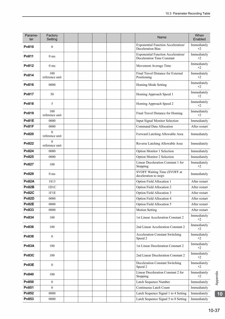
10.3 Parameter Recording Table
10-37
10
Ap
pe
nd
ix
Pn810 0 Exponential Function Acceleration/Deceleration Bias
Immediately∗2
Pn811 0 ms Exponential Function Acceleration/Deceleration Time Constant
Immediately∗2
Pn812 0 ms Movement Average Time Immediately∗2
Pn814 100reference unit
Final Travel Distance for External Positioning
Immediately∗2
Pn816 0000 Homing Mode Setting Immediately∗2
Pn817 50 Homing Approach Speed 1 Immediately∗2
Pn818 5 Homing Approach Speed 2 Immediately∗2
Pn819 100 reference unit Final Travel Distance for Homing Immediately
∗2
Pn81E 0000 Input Signal Monitor Selection Immediately
Pn81F 0000 Command Data Allocation After restart
Pn820 0reference unit Forward Latching Allowable Area Immediately
Pn822 0reference unit Reverse Latching Allowable Area Immediately
Pn824 0000 Option Monitor 1 Selection Immediately
Pn825 0000 Option Monitor 2 Selection Immediately
Pn827 100 Linear Deceleration Constant 1 for Stopping
Immediately∗2
Pn829 0 ms SVOFF Waiting Time (SVOFF at deceleration to stop) Immediately
Pn82A 1813 Option Field Allocation 1 After restart
Pn82B 1D1C Option Field Allocation 2 After restart
Pn82C 1F1E Option Field Allocation 3 After restart
Pn82D 0000 Option Field Allocation 4 After restart
Pn82E 0000 Option Field Allocation 5 After restart
Pn833 0000 Motion Setting After restart
Pn834 100 1st Linear Acceleration Constant 2 Immediately∗2
Pn836 100 2nd Linear Acceleration Constant 2 Immediately∗2
Pn838 0 Acceleration Constant Switching Speed 2
Immediately∗2
Pn83A 100 1st Linear Deceleration Constant 2 Immediately∗2
Pn83C 100 2nd Linear Deceleration Constant 2 Immediately∗2
Pn83E 0 Deceleration Constant Switching Speed 2
Immediately∗2
Pn840 100 Linear Deceleration Constant 2 for Stopping
Immediately∗2
Pn850 0 Latch Sequence Number Immediately
Pn851 0 Continuous Latch Count Immediately
Pn852 0000 Latch Sequence Signal 1 to 4 Setting Immediately
Pn853 0000 Latch Sequence Signal 5 to 8 Setting Immediately
Parame-ter
Factory Setting Name When
Enabled
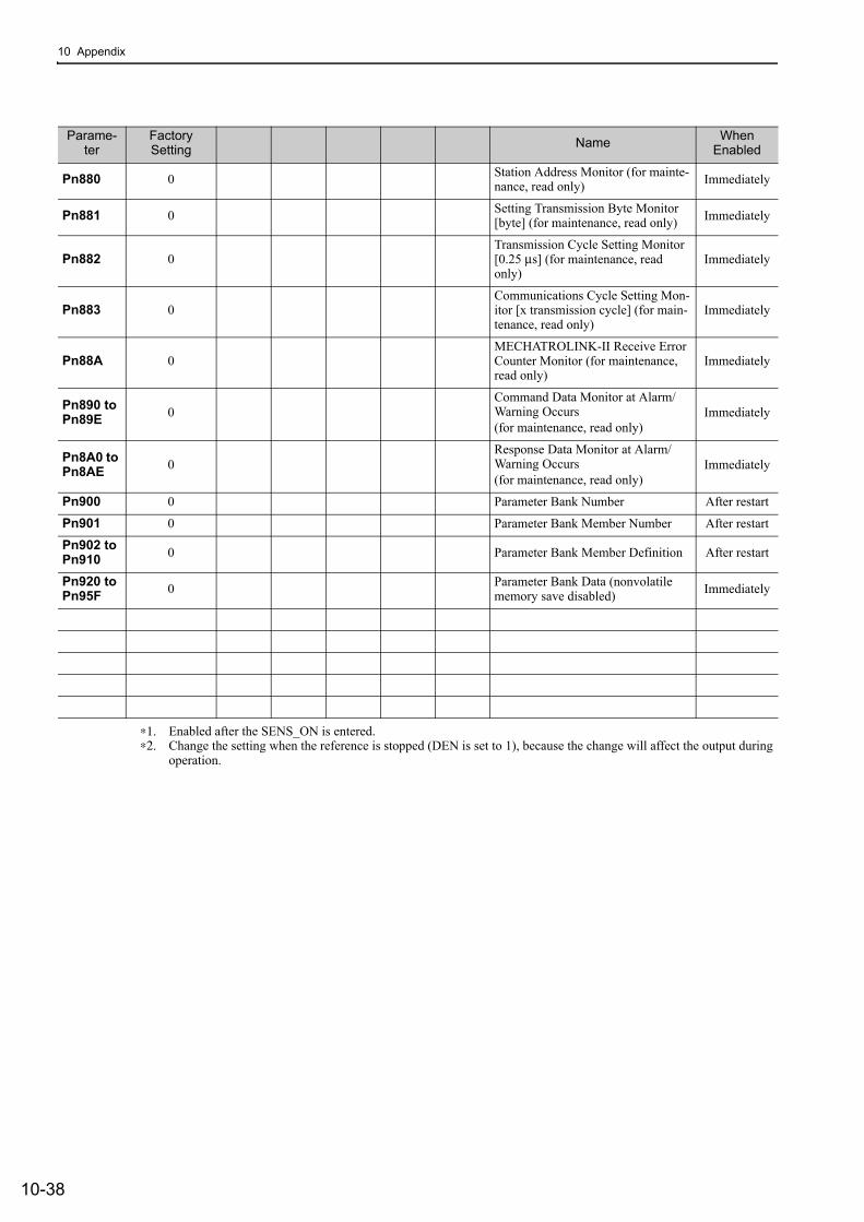
10 Appendix
10-38
∗1. Enabled after the SENS_ON is entered.∗2. Change the setting when the reference is stopped (DEN is set to 1), because the change will affect the output during
operation.
Pn880 0 Station Address Monitor (for mainte-nance, read only) Immediately
Pn881 0 Setting Transmission Byte Monitor [byte] (for maintenance, read only) Immediately
Pn882 0Transmission Cycle Setting Monitor [0.25 μs] (for maintenance, read only)
Immediately
Pn883 0Communications Cycle Setting Mon-itor [x transmission cycle] (for main-tenance, read only)
Immediately
Pn88A 0MECHATROLINK-II Receive Error Counter Monitor (for maintenance, read only)
Immediately
Pn890 to Pn89E 0
Command Data Monitor at Alarm/Warning Occurs(for maintenance, read only)
Immediately
Pn8A0 to Pn8AE 0
Response Data Monitor at Alarm/Warning Occurs(for maintenance, read only)
Immediately
Pn900 0 Parameter Bank Number After restart
Pn901 0 Parameter Bank Member Number After restart
Pn902 to Pn910 0 Parameter Bank Member Definition After restart
Pn920 to Pn95F 0 Parameter Bank Data (nonvolatile
memory save disabled) Immediately
Parame-ter
Factory Setting Name When
Enabled
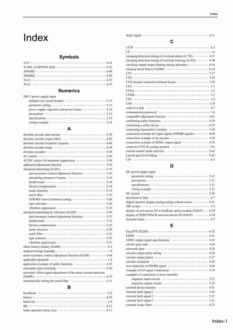
Index
Index-1
Index
Symbols/CLT - - - - - - - - - - - - - - - - - - - - - - - - - - - - - - - - - - - - - - - - - 4-34/G-SEL of OPTION field - - - - - - - - - - - - - - - - - - - - - - - - - - - 5-55/HWBB1 - - - - - - - - - - - - - - - - - - - - - - - - - - - - - - - - - - - - - - 4-49/HWBB2 - - - - - - - - - - - - - - - - - - - - - - - - - - - - - - - - - - - - - - 4-49/N-CL - - - - - - - - - - - - - - - - - - - - - - - - - - - - - - - - - - - - - - - - 4-33/P-CL - - - - - - - - - - - - - - - - - - - - - - - - - - - - - - - - - - - - - - - - 4-33
Numerics200 V power supply input
molded-case circuit breaker - - - - - - - - - - - - - - - - - - - - - - 3-15parameter setting - - - - - - - - - - - - - - - - - - - - - - - - - - - - - 3-13power supply capacities and power losses - - - - - - - - - - - - - 3-14precautions - - - - - - - - - - - - - - - - - - - - - - - - - - - - - - - - - 3-13specifications - - - - - - - - - - - - - - - - - - - - - - - - - - - - - - - - 3-13wiring example - - - - - - - - - - - - - - - - - - - - - - - - - - - - - - - 3-14
Aabsolute encoder data backup - - - - - - - - - - - - - - - - - - - - - - - - 4-36absolute encoder origin offset - - - - - - - - - - - - - - - - - - - - - - - - 4-45absolute encoder reception sequence - - - - - - - - - - - - - - - - - - - 4-40absolute encoder setup - - - - - - - - - - - - - - - - - - - - - - - - - - - - - 4-39absolute encoders - - - - - - - - - - - - - - - - - - - - - - - - - - - - - - - - 4-35AC reactor - - - - - - - - - - - - - - - - - - - - - - - - - - - - - - - - - - - - - 3-36AC/DC reactor for harmonic suppression - - - - - - - - - - - - - - - - 3-36additional adjustment function - - - - - - - - - - - - - - - - - - - - - - - 5-55advanced autotuning (Fn201) - - - - - - - - - - - - - - - - - - - - - - - - 5-16
anti-resonance control adjustment function - - - - - - - - - - - - 5-23calculating moment of inertia - - - - - - - - - - - - - - - - - - - - - 5-19feedforward - - - - - - - - - - - - - - - - - - - - - - - - - - - - - - - - - 5-24friction compensation - - - - - - - - - - - - - - - - - - - - - - - - - - 5-24mode selection - - - - - - - - - - - - - - - - - - - - - - - - - - - - - - - 5-19notch filter - - - - - - - - - - - - - - - - - - - - - - - - - - - - - - - - - - 5-23STROKE (travel distance) setting - - - - - - - - - - - - - - - - - - 5-20type selection - - - - - - - - - - - - - - - - - - - - - - - - - - - - - - - - 5-20vibration suppression - - - - - - - - - - - - - - - - - - - - - - - - - - - 5-23
advanced autotuning by reference (Fn202) - - - - - - - - - - - - - - - 5-26anti-resonance control adjustment function - - - - - - - - - - - - 5-31feedforward - - - - - - - - - - - - - - - - - - - - - - - - - - - - - - - - - 5-32friction compensation - - - - - - - - - - - - - - - - - - - - - - - - - - 5-32mode selection - - - - - - - - - - - - - - - - - - - - - - - - - - - - - - - 5-29notch filter - - - - - - - - - - - - - - - - - - - - - - - - - - - - - - - - - - 5-31type selection - - - - - - - - - - - - - - - - - - - - - - - - - - - - - - - - 5-29vibration suppression - - - - - - - - - - - - - - - - - - - - - - - - - - - 5-31
alarm history display (Fn000) - - - - - - - - - - - - - - - - - - - - - - - - - 6-3ambient/storage humidity - - - - - - - - - - - - - - - - - - - - - - - - - - - - 1-4annti-resonance control adjustment function (Fn204) - - - - - - - - 5-44applicable standards - - - - - - - - - - - - - - - - - - - - - - - - - - - - - - - 1-4application example of safety functions - - - - - - - - - - - - - - - - - 4-53atutomatic gain switching - - - - - - - - - - - - - - - - - - - - - - - - - - - 5-56automatic offset-signal adjustment of the motor current detection (Fn00E) - - - - - - - - - - - - - - - - - - - - - - - - - - - - - - - - - - - - - - - 6-19automatically setting the notch filter - - - - - - - - - - - - - - - - - - - 5-11
Bbaseblock - - - - - - - - - - - - - - - - - - - - - - - - - - - - - - - - - - - - - - 2-2battery - - - - - - - - - - - - - - - - - - - - - - - - - - - - - - - - - - - - - - - - 4-36baud rate - - - - - - - - - - - - - - - - - - - - - - - - - - - - - - - - - - - - - - - 1-6BK - - - - - - - - - - - - - - - - - - - - - - - - - - - - - - - - - - - - - - - - - - 4-12brake operation delay time - - - - - - - - - - - - - - - - - - - - - - - - - - 4-11
brake signal - - - - - - - - - - - - - - - - - - - - - - - - - - - - - - - - - - - - 4-11
CCCW - - - - - - - - - - - - - - - - - - - - - - - - - - - - - - - - - - - - - - - - - 4-5CE - - - - - - - - - - - - - - - - - - - - - - - - - - - - - - - - - - - - - - - - - - - - xichanging detection timing of overload alarm (A.720) - - - - - - - - 4-21changing detection timing of overload warning (A.910) - - - - - - 4-20checking output torque limiting during operation - - - - - - - - - - - 4-34clearing alarm history (Fn006) - - - - - - - - - - - - - - - - - - - - - - - 6-14CN1 - - - - - - - - - - - - - - - - - - - - - - - - - - - - - - - - - - - - - - - - - 3-17CN2 - - - - - - - - - - - - - - - - - - - - - - - - - - - - - - - - - - - - - - - - - 3-29CN2 encoder connector terminal layout - - - - - - - - - - - - - - - - - 3-29CN3 - - - - - - - - - - - - - - - - - - - - - - - - - - - - - - - - - - - - - - - - - - 1-2CN6A - - - - - - - - - - - - - - - - - - - - - - - - - - - - - - - - - - - - - - - - - 1-2CN6B - - - - - - - - - - - - - - - - - - - - - - - - - - - - - - - - - - - - - - - - - 1-2CN7 - - - - - - - - - - - - - - - - - - - - - - - - - - - - - - - - - - - - - - - - - - 1-2CN8 - - - - - - - - - - - - - - - - - - - - - - - - - - - - - - - - - - - - - - - - - 3-18coast to a stop - - - - - - - - - - - - - - - - - - - - - - - - - - - - - - - - - - - 4-7communication protocol - - - - - - - - - - - - - - - - - - - - - - - - - - - - 1-6compatible adjustment function - - - - - - - - - - - - - - - - - - - - - - 5-63confirming safety functions - - - - - - - - - - - - - - - - - - - - - - - - - 4-54connecting a safety device - - - - - - - - - - - - - - - - - - - - - - - - - - 4-55connecting regenerative resistors - - - - - - - - - - - - - - - - - - - - - 3-30connection example for input signals (HWBB signals) - - - - - - - 4-49connection example of an encoder - - - - - - - - - - - - - - - - - - - - - 3-28connection example of EDM1 output signal - - - - - - - - - - - - - - 4-52connector CN5 for analog monitor - - - - - - - - - - - - - - - - - - - - - 5-6current control mode selection - - - - - - - - - - - - - - - - - - - - - - - 5-62current gain level setting - - - - - - - - - - - - - - - - - - - - - - - - - - - 5-62CW - - - - - - - - - - - - - - - - - - - - - - - - - - - - - - - - - - - - - - - - - - 4-5
DDC power supply input
parameter setting - - - - - - - - - - - - - - - - - - - - - - - - - - - - - 3-13precautions - - - - - - - - - - - - - - - - - - - - - - - - - - - - - - - - - 3-11specifications - - - - - - - - - - - - - - - - - - - - - - - - - - - - - - - - 3-11wiring example - - - - - - - - - - - - - - - - - - - - - - - - - - - - - - 3-12
DC reactor - - - - - - - - - - - - - - - - - - - - - - - - - - - - - - - - - - - - 3-36decelerate to stop - - - - - - - - - - - - - - - - - - - - - - - - - - - - - - - - - 4-7digital operator display during testing without motor - - - - - - - - 4-31DIP switch - - - - - - - - - - - - - - - - - - - - - - - - - - - - - - - - - - - - - 1-2display of servomotor ID in feedback option module (Fn01F) - - 6-29display of SERVOPACK and servomotor ID (Fn01E) - - - - - - - 6-28dynamic brake - - - - - - - - - - - - - - - - - - - - - - - - - - - - - - - - - - - 4-7
EEasyFFT (Fn206) - - - - - - - - - - - - - - - - - - - - - - - - - - - - - - - - 6-32EDM1 - - - - - - - - - - - - - - - - - - - - - - - - - - - - - - - - - - - - - - - 4-51EDM1 output signal specifications - - - - - - - - - - - - - - - - - - - - 4-52electric gear ratio - - - - - - - - - - - - - - - - - - - - - - - - - - - - - - - - 4-24electronic gear - - - - - - - - - - - - - - - - - - - - - - - - - - - - - - - - - - 4-24encoder output pulse setting - - - - - - - - - - - - - - - - - - - - - - - - - 4-28encoder output pulses - - - - - - - - - - - - - - - - - - - - - - - - - - - - - 4-27encoder resolution - - - - - - - - - - - - - - - - - - - - - - - - - - - - - - - 4-28error detection in HWBB signal - - - - - - - - - - - - - - - - - - - - - - 4-48example of I/O signal connections - - - - - - - - - - - - - - - - - - - - - 3-19examples of connection to host controller
sequence input circuits - - - - - - - - - - - - - - - - - - - - - - - - - 3-23sequence output circuits - - - - - - - - - - - - - - - - - - - - - - - - 3-25
external device monitor - - - - - - - - - - - - - - - - - - - - - - - - - - - - 4-51external latch signal 1 - - - - - - - - - - - - - - - - - - - - - - - - - - - - - 3-20external latch signal 2 - - - - - - - - - - - - - - - - - - - - - - - - - - - - - 3-21external latch signal 3 - - - - - - - - - - - - - - - - - - - - - - - - - - - - - 3-21external torque limit - - - - - - - - - - - - - - - - - - - - - - - - - - - - - - 4-33
Index
Index-2
Ffeedforward control compensation - - - - - - - - - - - - - - - - - - - - - 5-63feedforward reference - - - - - - - - - - - - - - - - - - - - - - - - - - - - - 5-63FG - - - - - - - - - - - - - - - - - - - - - - - - - - - - - - - - - - - - - - - - - - 3-19forward external torque limit - - - - - - - - - - - - - - - - - - - - - - - - - 4-33friction compensation - - - - - - - - - - - - - - - - - - - - - - - - - - - - - - 5-60fully-closed loop control
absolute external encoder reception sequence - - - - - - - - - - 8-14alarm detection - - - - - - - - - - - - - - - - - - - - - - - - - - - - - - - 8-17analog monitor signal - - - - - - - - - - - - - - - - - - - - - - - - - - - 8-18analog signal input timing - - - - - - - - - - - - - - - - - - - - - - - - - 8-5connection example of external encoder by Heidenhain - - - - - 8-6connection example of external encoder by Mitutoyo - - - - - - 8-7connection example of external encoder by Renishaw - - - - - - 8-8electronic gear - - - - - - - - - - - - - - - - - - - - - - - - - - - - - - - 8-17encoder output pulses - - - - - - - - - - - - - - - - - - - - - - - - - - - 8-13internal configuration - - - - - - - - - - - - - - - - - - - - - - - - - - - - 8-3motor rotation direction - - - - - - - - - - - - - - - - - - - - - - - - - 8-11serial converter unit - - - - - - - - - - - - - - - - - - - - - - - - - - - - - 8-4sine wave pitch (frequency) for an external encoder - - - - - - 8-12speed feedback method - - - - - - - - - - - - - - - - - - - - - - - - - 8-18system configuration - - - - - - - - - - - - - - - - - - - - - - - - - - - - 8-2
Ggain adjustment of analog monitor output (Fn00D) - - - - - - - - - - 6-17Gr.1 alarm - - - - - - - - - - - - - - - - - - - - - - - - - - - - - - - - - - - - - 4-15Gr.2 alarm - - - - - - - - - - - - - - - - - - - - - - - - - - - - - - - - - - - - - 4-15grounding - - - - - - - - - - - - - - - - - - - - - - - - - - - - - - - - - - - - - - 3-33
Hhard wire base block (HWBB) function - - - - - - - - - - - - - - - - - 4-46hard wire base block (HWBB) state - - - - - - - - - - - - - - - - - - - - 4-47holding brake signal - - - - - - - - - - - - - - - - - - - - - - - - - - - - - - - 4-12holding brakes - - - - - - - - - - - - - - - - - - - - - - - - - - - - - - - - - - 4-10homing deceleration LS - - - - - - - - - - - - - - - - - - - - - - - - - - - - 3-20HWBB state - - - - - - - - - - - - - - - - - - - - - - - - - - - - - - - - - - - - 4-47
II/O signal (CN1)
connector terminal layout - - - - - - - - - - - - - - - - - - - - - - - - 3-18names and functions - - - - - - - - - - - - - - - - - - - - - - - - - - - 3-17
infinite time operation - - - - - - - - - - - - - - - - - - - - - - - - - - - - - - 6-9initial incremental pulses - - - - - - - - - - - - - - - - - - - - - - - - - - - 4-41initializing parameter settings (Fn005) - - - - - - - - - - - - - - - - - - 6-13input signal allocations - - - - - - - - - - - - - - - - - - - - - - - - - - - - - 3-20instantaneous power interruption settings - - - - - - - - - - - - - - - - 4-16internal torque limit - - - - - - - - - - - - - - - - - - - - - - - - - - - - - - - 4-32
JJOG operation (Fn002) - - - - - - - - - - - - - - - - - - - - - - - - - - - - - - 6-4
LLED(COM) - - - - - - - - - - - - - - - - - - - - - - - - - - - - - - - - - - - - - 1-2LED(POWER) - - - - - - - - - - - - - - - - - - - - - - - - - - - - - - - - - - - 1-2limit switches - - - - - - - - - - - - - - - - - - - - - - - - - - - - - - - - - - - - 4-6list of alarms - - - - - - - - - - - - - - - - - - - - - - - - - - - - - - - - - - - - - 9-2list of monitor modes - - - - - - - - - - - - - - - - - - - - - - - - - - 7-2, 10-32list of warnings - - - - - - - - - - - - - - - - - - - - - - - - - - - - - - - - - - 9-21
Mmain circuit
terminal names and functions - - - - - - - - - - - - - - - - - - - - - - 3-3main circuit wire size - - - - - - - - - - - - - - - - - - - - - - - - - - - - - - - 3-4main circuit wiring examples - - - - - - - - - - - - - - - - - - - - - - - - - - 3-6manual gain switching - - - - - - - - - - - - - - - - - - - - - - - - - - - - - 5-55
manual offset-signal adjustment of the motor current detection (Fn00F) - - - - - - - - - - - - - - - - - - - - - - - - - - - - - - - - - - - - - - - 6-20MECHATROLINK-II communication connectors - - - - - - - - - - - 1-2MECHATROLINK-II function specifications - - - - - - - - - - - - - - 1-6monitor mode (Un ) - - - - - - - - - - - - - - - - - - - - - - - - - - 2-10monitor mode display - - - - - - - - - - - - - - - - - - - - - - - - - - - - - - 7-3monitoring analog signals - - - - - - - - - - - - - - - - - - - - - - - - - - - 5-5motor overload detection level - - - - - - - - - - - - - - - - - - - - - - - 4-20multiturn limit disagreement alarm (A.CC0) - - - - - - - - - - - - - - 4-44multiturn limit setting - - - - - - - - - - - - - - - - - - - - - - - - - - - - - 4-43
Nnoise filter - - - - - - - - - - - - - - - - - - - - - - - - - - - - - - - - - - - - - 3-33North American safety standards - - - - - - - - - - - - - - - - - - - - - - - - xiN-OT - - - - - - - - - - - - - - - - - - - - - - - - - - - - - - - - - - - - - - - - - 4-6notch filters - - - - - - - - - - - - - - - - - - - - - - - - - - - - - - - - - - - - 5-68
Ooffset adjustment of analog monitor output (Fn00C) - - - - - - - - - 6-15one-parameter tuning (Fn203) - - - - - - - - - - - - - - - - - - - - - - - - 5-34
anti-resonance control adjustment function - - - - - - - - - - - - 5-40feedforward - - - - - - - - - - - - - - - - - - - - - - - - - - - - - - - - - 5-41friction compensation - - - - - - - - - - - - - - - - - - - - - - - - - - 5-40notch filter - - - - - - - - - - - - - - - - - - - - - - - - - - - - - - - - - - 5-40tuning mode - - - - - - - - - - - - - - - - - - - - - - - - - - - - - 5-36, 5-38type selection - - - - - - - - - - - - - - - - - - - - - - - - - - - - 5-36, 5-38
one-parameter tuning example - - - - - - - - - - - - - - - - - - - - - - - 5-42online vibration monitor (Fn207) - - - - - - - - - - - - - - - - - - - - - - 6-36origin search (Fn003) - - - - - - - - - - - - - - - - - - - - - - - - - - - - - - 6-6origin setting (Fn020) - - - - - - - - - - - - - - - - - - - - - - - - - - - - - 6-30output phase - - - - - - - - - - - - - - - - - - - - - - - - - - - - - - - - - - - - 4-27output signal allocation - - - - - - - - - - - - - - - - - - - - - - - - - - - - 3-22output signals - - - - - - - - - - - - - - - - - - - - - - - - - - - - - - - - - - - 3-17overtravel (OT) - - - - - - - - - - - - - - - - - - - - - - - - - - - - - - - - - - 4-6
PP control - - - - - - - - - - - - - - - - - - - - - - - - - - - - - - - - - - - - - - 5-63panel display - - - - - - - - - - - - - - - - - - - - - - - - - - - - - - - - - - - - 2-2PAO - - - - - - - - - - - - - - - - - - - - - - - - - - - - - - - - - - - - - - - - - 4-27paramete write prohibited setting (Fn010) - - - - - - - - - - - - - - - - 6-21parameter
explanation method for function selection type - - - - - - - - - - 2-5explanation method for parameter setting type - - - - - - - - - - - 2-5parameter setting mode for function selection type - - - - - - - - 2-9parameter setting mode for parameter setting type - - - - - - - - 2-7
parameter recording table - - - - - - - - - - - - - - - - - - - - - - - - - - 10-33parameter setting mode (Pn ) - - - - - - - - - - - - - - - - - - - - - 2-7parameters - - - - - - - - - - - - - - - - - - - - - - - - - - - - - - - - - - - - - 10-3PBO - - - - - - - - - - - - - - - - - - - - - - - - - - - - - - - - - - - - - - - - - 4-27PCO - - - - - - - - - - - - - - - - - - - - - - - - - - - - - - - - - - - - - - - - - 4-27PI control - - - - - - - - - - - - - - - - - - - - - - - - - - - - - - - - - - - - - 5-63P-OT - - - - - - - - - - - - - - - - - - - - - - - - - - - - - - - - - - - - - - - - - 4-6precautions for safety functions - - - - - - - - - - - - - - - - - - - - - - - 4-56precautions for wiring - - - - - - - - - - - - - - - - - - - - - - - - - - - - - 3-10precautions on connecting noise filter - - - - - - - - - - - - - - - - - - 3-34program JOG operation (Fn004) - - - - - - - - - - - - - - - - - - - - - - - 6-8protection class/pollution degree - - - - - - - - - - - - - - - - - - - - - - - 1-4
Rreference unit - - - - - - - - - - - - - - - - - - - - - - - - - - - - - - - - - - - 4-24resetting configuration error of option module (Fn014) - - - - - - - 6-25resetting the HWBB state - - - - - - - - - - - - - - - - - - - - - - - - - - - 4-48reverse external torque limit - - - - - - - - - - - - - - - - - - - - - - - - - 4-33risk assessment - - - - - - - - - - - - - - - - - - - - - - - - - - - - - - - - - - 4-46rotary switch - - - - - - - - - - - - - - - - - - - - - - - - - - - - - - - - - 1-2, 4-4rotational data specifications - - - - - - - - - - - - - - - - - - - - - - - - - 4-42
Index
Index-3
rotational serial data - - - - - - - - - - - - - - - - - - - - - - - - - - - - - - 4-41
Ssafety function - - - - - - - - - - - - - - - - - - - - - - - - - - - - - - - - - - 4-46safety function signal (CN8) names and functions - - - - - - - - - - 3-18safety precautions on adjustment of servo gains - - - - - - - - - - - - - 5-7SEMI-F47 function (torque limit function for low power supply voltage for main circuit) - - - - - - - - - - - - - - - - - - - - - - - - - - - - - - - - - 4-17servo gains - - - - - - - - - - - - - - - - - - - - - - - - - - - - - - - - - - - - - - 5-3servomotor model display (Fn011) - - - - - - - - - - - - - - - - - - - - 6-23servomotor rotation direction - - - - - - - - - - - - - - - - - - - - - - - - - 4-5SERVOPACKs
basic specifications - - - - - - - - - - - - - - - - - - - - - - - - - - - - - 1-4example of servo system configuration(SGDV- A11A) 1-16example of servo system configuration(SGDV- D11A) 1-17example of servo system configuration(SGDV- F11A) 1-15inspection and maintenance - - - - - - - - - - - - - - - - - - - - - - 1-19MECHATROLINK-II function specifications - - - - - - - - - - - 1-6model designation - - - - - - - - - - - - - - - - - - - - - - - - - - - - - 1-18part names - - - - - - - - - - - - - - - - - - - - - - - - - - - - - - - - - - - 1-2precautions when using more than one SERVOPACK - - - - 3-16ratings - - - - - - - - - - - - - - - - - - - - - - - - - - - - - - - - - - - - - - 1-3
setting monitor factor - - - - - - - - - - - - - - - - - - - - - - - - - - - - - - 5-6setting regenerative resistor capacity - - - - - - - - - - - - - - - - - - - 3-31settings for DIP switch - - - - - - - - - - - - - - - - - - - - - - - - - - - - - - 4-3settings for SW2 - - - - - - - - - - - - - - - - - - - - - - - - - - - - - - - - - - 4-3single-phase 200 V power supply input
molded-case circuit breaker - - - - - - - - - - - - - - - - - - - - - - 3-15parameter setting - - - - - - - - - - - - - - - - - - - - - - - - - - - - - 3-13power supply capacities and power losses - - - - - - - - - - - - - 3-14precautions - - - - - - - - - - - - - - - - - - - - - - - - - - - - - - - - - 3-13specifications - - - - - - - - - - - - - - - - - - - - - - - - - - - - - - - - 3-13wiring example - - - - - - - - - - - - - - - - - - - - - - - - - - - - - - - 3-14
soft start time setting - - - - - - - - - - - - - - - - - - - - - - - - - - - - - - - 1-4software limit settings - - - - - - - - - - - - - - - - - - - - - - - - - - - - - - 4-9software reset (Fn030) - - - - - - - - - - - - - - - - - - - - - - - - - - - - - 6-31software version display (Fn012) - - - - - - - - - - - - - - - - - - - - - - 6-24specifications of input signals (HWBB signals) - - - - - - - - - - - - 4-49speed control range - - - - - - - - - - - - - - - - - - - - - - - - - - - - - - - - 1-4speed detection method selection - - - - - - - - - - - - - - - - - - - - - - 5-62speed regulation - - - - - - - - - - - - - - - - - - - - - - - - - - - - - - - - - - 1-4station address - - - - - - - - - - - - - - - - - - - - - - - - - - - - - - - - - - - 1-6status display - - - - - - - - - - - - - - - - - - - - - - - - - - - - - - - - - - - - 2-2stopping method for servomotor after receiving SV_OFFcommand - - - - - - - - - - - - - - - - - - - - - - - - - - - - - - - - - - - - - - 4-14stopping method for servomotor when an alarm occurs - - - - - - - 4-15surrounding air/storage temperature - - - - - - - - - - - - - - - - - - - - - 1-4SW1 - - - - - - - - - - - - - - - - - - - - - - - - - - - - - - - - - - - - - - - 1-2, 4-4SW2 - - - - - - - - - - - - - - - - - - - - - - - - - - - - - - - - - - - - - - - - - - 1-2switching condition A - - - - - - - - - - - - - - - - - - - - - - - - - - - - - 5-56switching gain settings - - - - - - - - - - - - - - - - - - - - - - - - - - - - - 5-55
Tterminator - - - - - - - - - - - - - - - - - - - - - - - - - - - - - - - - - - - - - 3-27test without motor function - - - - - - - - - - - - - - - - - - - - - - - - - - 4-29time stamps - - - - - - - - - - - - - - - - - - - - - - - - - - - - - - - - - - - - - 6-3torque control tolerance - - - - - - - - - - - - - - - - - - - - - - - - - - - - - 1-4torque reference filter - - - - - - - - - - - - - - - - - - - - - - - - - - - - - 5-68transmission cycle - - - - - - - - - - - - - - - - - - - - - - - - - - - - - - - - - 1-6trial operation
inspection and checking before trial operation - - - - - - - - - - 4-22trial Operation via MECHATROLINK-II - - - - - - - - - - - - - 4-23
troubleshooting malfunction based on operation and conditions of the servomotor - - - - - - - - - - - - - - - - - - - - - - - - - - - - - - - - - - - - 9-25troubleshooting of alarms - - - - - - - - - - - - - - - - - - - - - - - - - - - - 9-6troubleshooting of warnings - - - - - - - - - - - - - - - - - - - - - - - - - 9-22
tuning parameters - - - - - - - - - - - - - - - - - - - - - - - - - - - - - - - - - 2-6tuning-less function - - - - - - - - - - - - - - - - - - - - - - - - - - - - - - 5-10tuning-less level settings - - - - - - - - - - - - - - - - - - - - - - - - - - - 5-11
UUL standards - - - - - - - - - - - - - - - - - - - - - - - - - - - - - - - - - - - - - xiusing the mode switch (P/PI switching) - - - - - - - - - - - - - - - - - 5-63utility function mode (Fn ) - - - - - - - - - - - - - - - - - - - - - - - 2-3utility functions - - - - - - - - - - - - - - - - - - - - - - - - - - - - - - - - - 10-2
Vvibration detection level initialization (Fn01B) - - - - - - - - - - - - 6-26vibration suppression function (Fn205) - - - - - - - - - - - - - - - - - 5-50vibration/shock resistance - - - - - - - - - - - - - - - - - - - - - - - - - - - 1-4
Wwiring for noise control - - - - - - - - - - - - - - - - - - - - - - - - - - - - 3-32wiring MECHATROLINK-II communications - - - - - - - - - - - - 3-27
Zzero clamp mode - - - - - - - - - - - - - - - - - - - - - - - - - - - - - - - - - 4-7
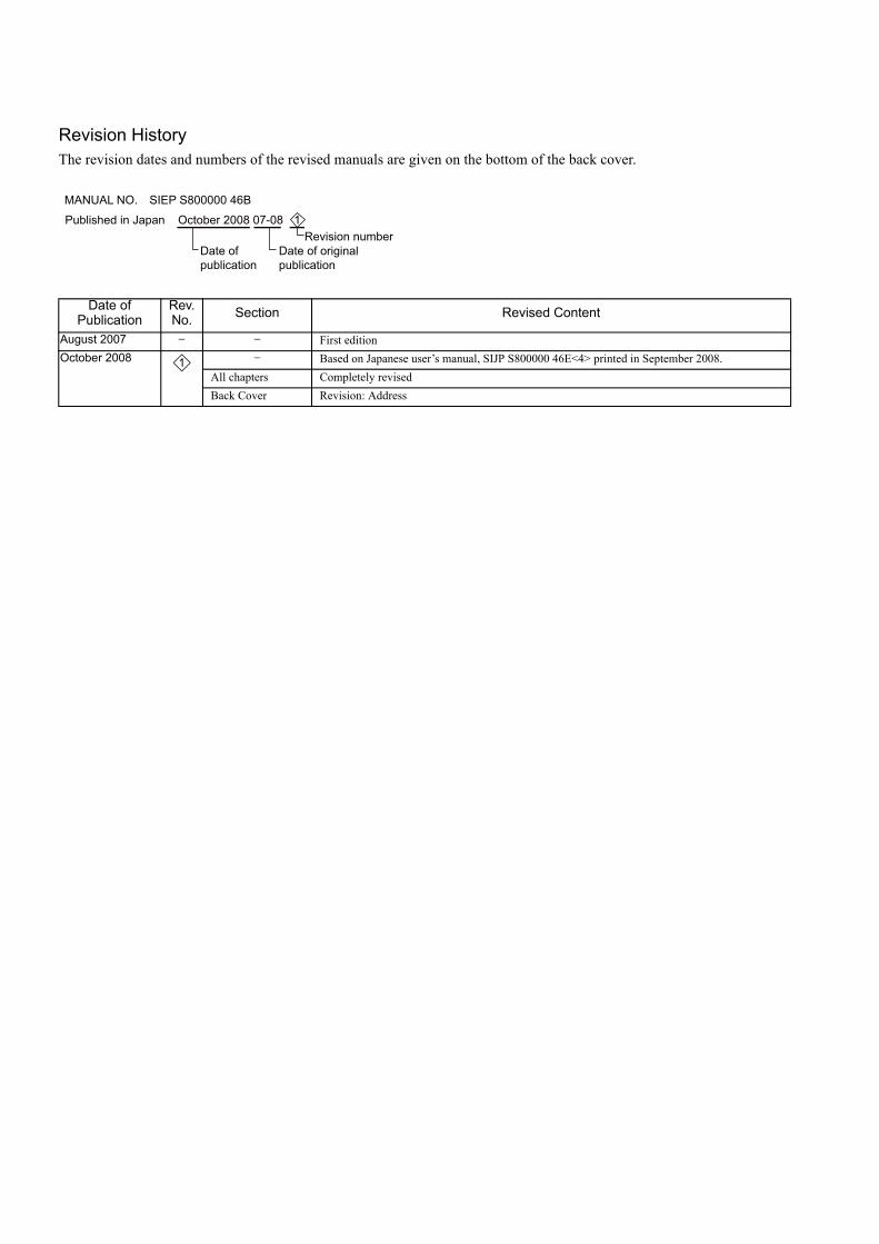
Revision HistoryThe revision dates and numbers of the revised manuals are given on the bottom of the back cover.
Date of Publication
Rev. No. Section Revised Content
August 2007 − − First editionOctober 2008 − Based on Japanese user’s manual, SIJP S800000 46E<4> printed in September 2008.
All chapters Completely revisedBack Cover Revision: Address
MANUAL NO. SIEP S800000 46B
Published in Japan October 2008 07-08
Date of publication
Date of original publication
Revision number 1
1
英文 No.4-5 (A4) メカトロ製品用
YASKAWA ELECTRIC CORPORATION
In the event that the end user of this product is to be the military and said product is to be employed in any weapons systems or the manufacture thereof, the export will fall under the relevant regulations as stipulated in the Foreign Exchange and Foreign Trade Regulations. Therefore, be sure to follow all procedures and submit all relevant documentation according to any and all rules, regulations and laws that may apply.
Specifications are subject to change without notice for ongoing product modifications and improvements.
© 2007-2008 YASKAWA ELECTRIC CORPORATION. All rights reserved.
YASKAWA
IRUMA BUSINESS CENTER (SOLUTION CENTER)480, Kamifujisawa, Iruma, Saitama 358-8555, JapanPhone 81-4-2962-5696 Fax 81-4-2962-6138
YASKAWA ELECTRIC AMERICA, INC.2121 Norman Drive South, Waukegan, IL 60085, U.S.A.Phone 1-847-887-7000 Fax 1-847-887-7370
YASKAWA ELETRICO DO BRASIL LTDA.Avenida Fagundes Filho, 620 Sao Paulo-SP CEP 04304-000, Brazil Phone 55-11-3585-1100 Fax 55-11-5581-8795
YASKAWA ELECTRIC EUROPE GmbHHauptstraβe 185, 65760 Eschborn, GermanyPhone 49-6196-569-300 Fax 49-6196-569-398
YASKAWA ELECTRIC UK LTD.1 Hunt Hill Orchardton Woods Cumbernauld, G68 9LF, United KingdomPhone 44-1236-735000 Fax 44-1236-458182
YASKAWA ELECTRIC KOREA CORPORATION7F, Doore Bldg. 24, Yeoido-dong, Youngdungpo-Ku, Seoul 150-877, KoreaPhone 82-2-784-7844 Fax 82-2-784-8495
YASKAWA ELECTRIC (SINGAPORE) PTE. LTD.151 Lorong Chuan, #04-01, New Tech Park 556741, SingaporePhone 65-6282-3003 Fax 65-6289-3003
YASKAWA ELECTRIC (SHANGHAI) CO., LTD.No.18 Xizang Zhong Road. Room 1702-1707, Harbour Ring Plaza Shanghai 200001, ChinaPhone 86-21-5385-2200 Fax 86-21-5385-3299
YASKAWA ELECTRIC (SHANGHAI) CO., LTD. BEIJING OFFICERoom 1011A, Tower W3 Oriental Plaza, No.1 East Chang An Ave.,Dong Cheng District, Beijing 100738, ChinaPhone 86-10-8518-4086 Fax 86-10-8518-4082
YASKAWA ELECTRIC TAIWAN CORPORATION9F, 16, Nanking E. Rd., Sec. 3, Taipei, TaiwanPhone 886-2-2502-5003 Fax 886-2-2505-1280
Published in Japan October 2008 07-8
MANUAL NO. SIEP S800000 46B
08-5-31 -0
Σ-V Series
Rotational MotorMECHATROLINK-II Communications Reference
USER'S MANUAL Design and Maintenance
AC Servo Drives