Shear Strength of Soil - cv.nctu.edu.t · zShear strength parameters ... zSimple shear, direct...
104
Shear Strength of Soil Hsin-yu Shan Dept. of Civil Engineering National Chiao Tung University
Transcript of Shear Strength of Soil - cv.nctu.edu.t · zShear strength parameters ... zSimple shear, direct...
Shear Strength of Soil
Hsin-yu ShanDept. of Civil Engineering
National Chiao Tung University
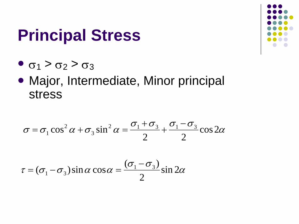
Principal Stressσ1 > σ2 > σ3
Major, Intermediate, Minor principal stress
ασσσσασασσ 2cos22
sincos 313123
21
−+
+=+=
ασσαασστ 2sin2
)(cossin)( 3131
−=−=
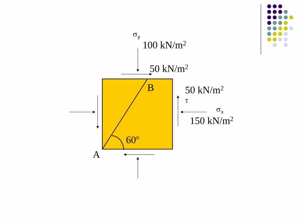
σy
100 kN/m2
50 kN/m2
60°
B
A
150 kN/m2
50 kN/m2
σx
τ

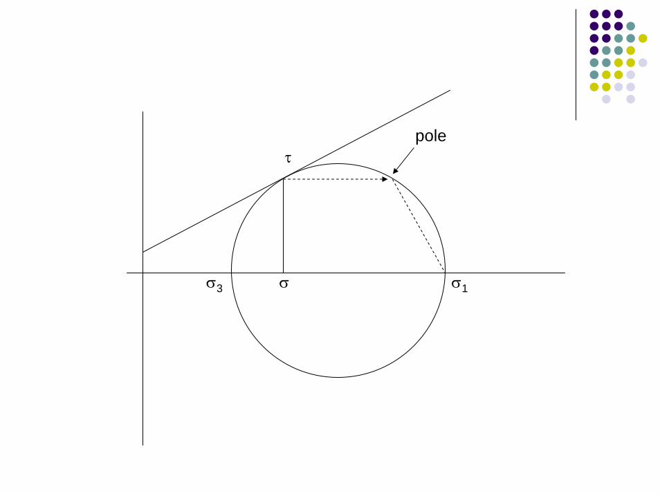
Pole Point
The point on the Mohr’s circle from which any extended straight line will intersect the circle at a point corresponding to stress on a plane parallel to the extended line
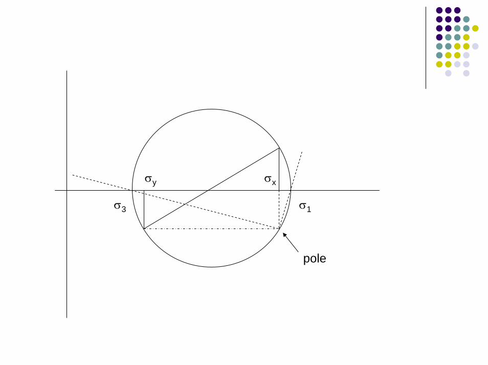
σxσy
σ1σ3
pole
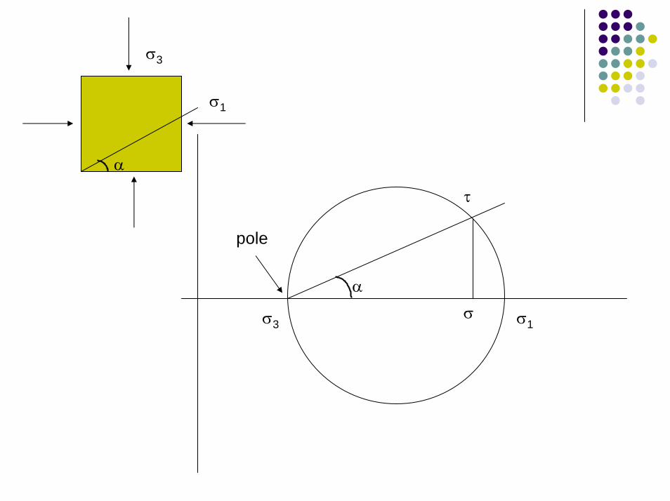
σ3
α
σ1
σ
τ
α
pole
σ1σ3
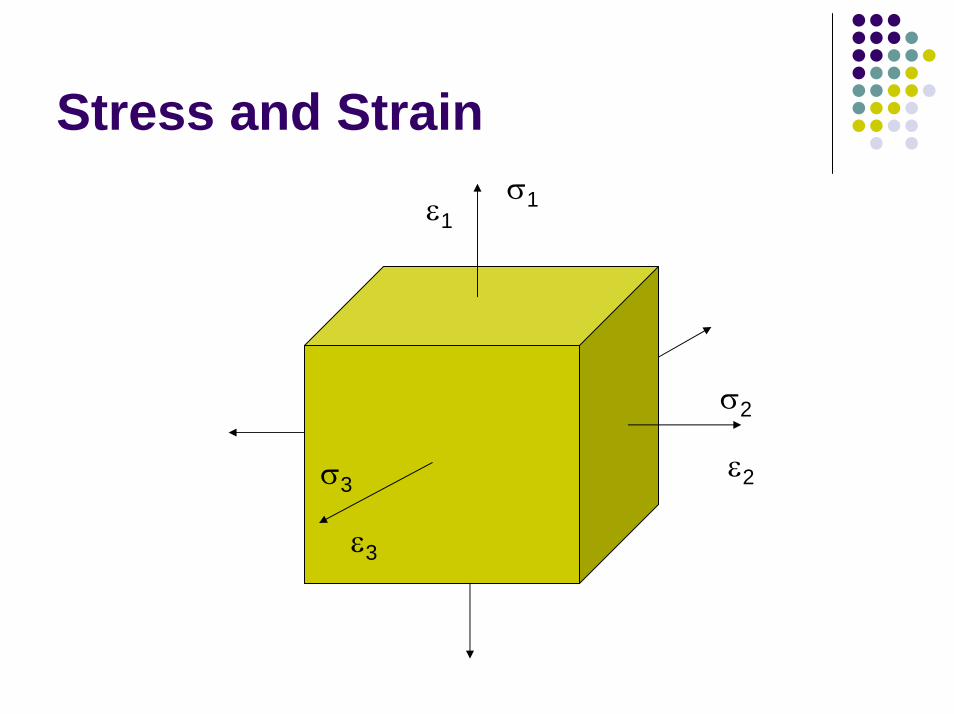
Stress and Strainσ1ε1
σ2
σ3ε2
ε3
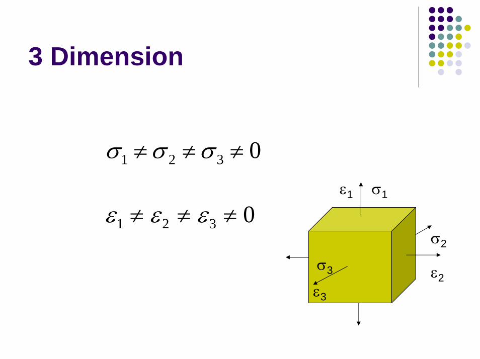
3 Dimension
0321 ≠≠≠ σσσσ1ε1
σ2
σ3 ε2ε3
ε ε ε1 2 3 0≠ ≠ ≠
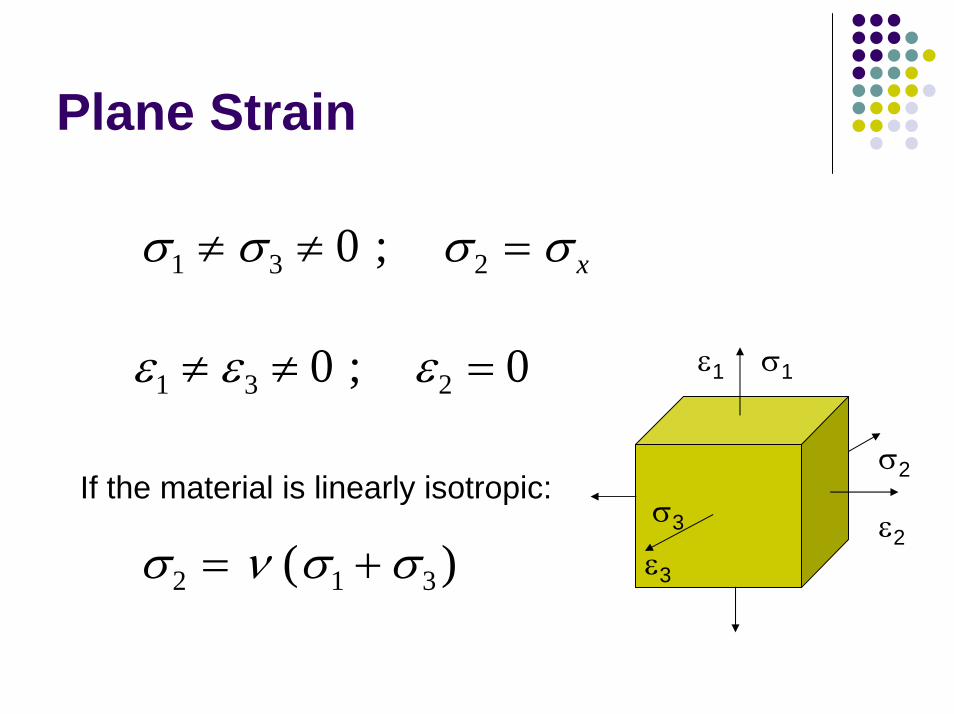
Plane Strain
σ σ σ σ1 3 20≠ ≠ =; x
ε ε ε1 3 20 0≠ ≠ =; σ1ε1
σ2
σ3 ε2ε3
If the material is linearly isotropic:
σ ν σ σ2 1 3= +( )
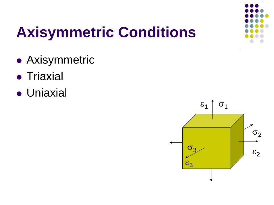
Axisymmetric Conditions
AxisymmetricTriaxialUniaxial
σ1ε1
σ2
σ3 ε2ε3
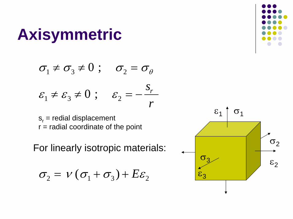
Axisymmetric
σ σ σ σθ1 3 20≠ ≠ =;
ε ε ε1 3 20≠ ≠ = − ; srr
sr = redial displacementr = radial coordinate of the point
σ ν σ σ ε2 1 3 2= + + ( ) E
σ1ε1
σ2
σ3 ε2ε3
For linearly isotropic materials:
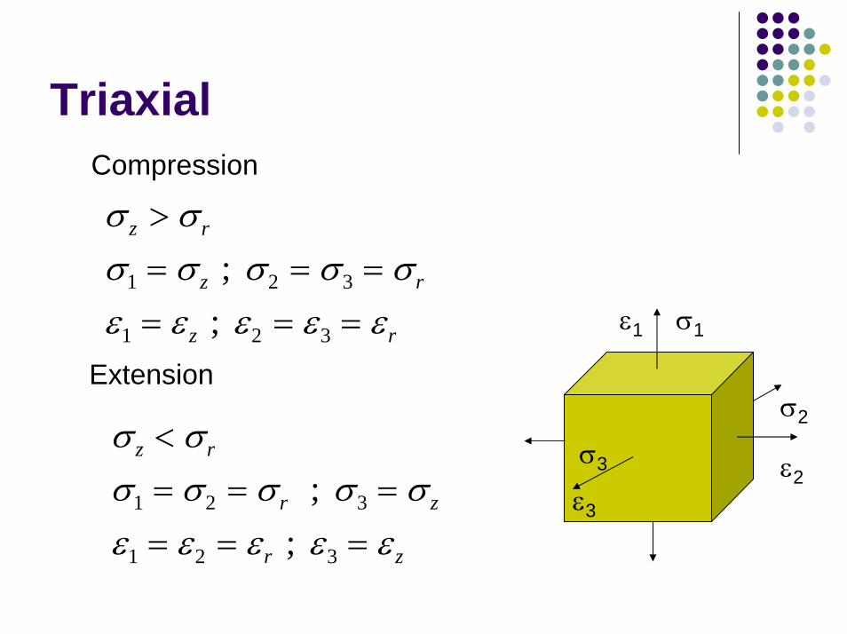
TriaxialCompression
σ σz r> σ σ σ σ σ1 2 3= = =z r ;ε ε ε ε ε1 2 3= = =z r ;
Extension
σ σz r<σ σ σ σ σ1 2 3= = =r z ;ε ε ε ε ε1 2 3= = =r z;
σ1ε1
σ2
σ3 ε2ε3
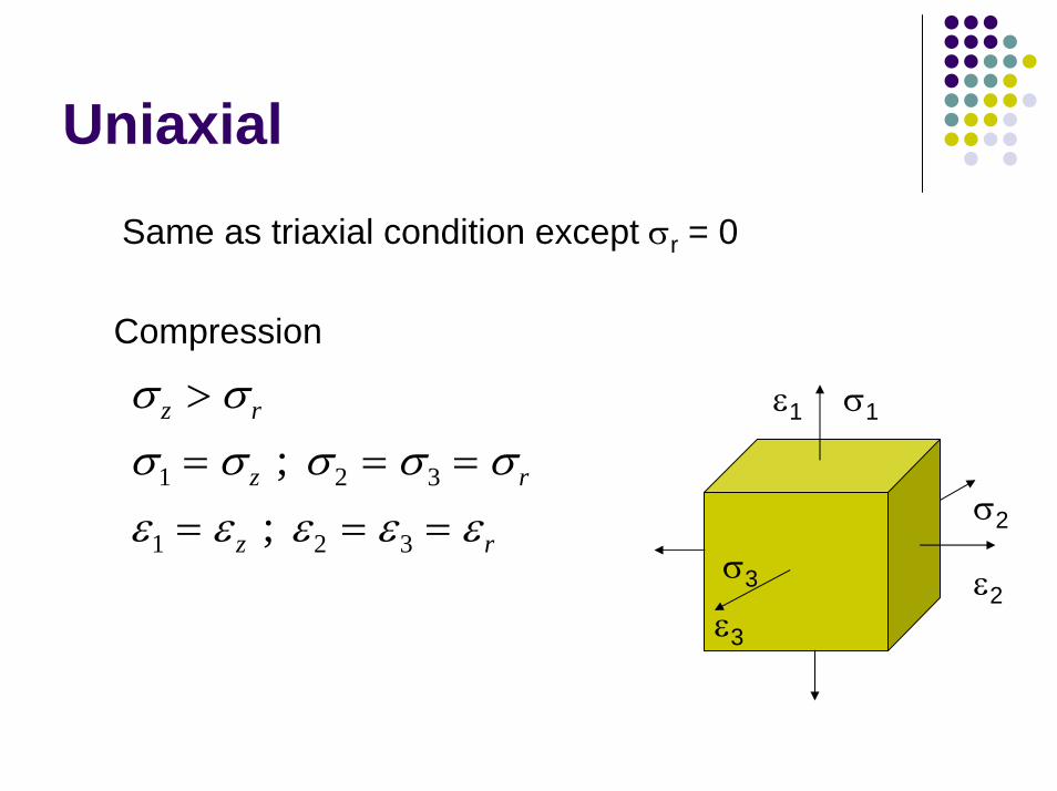
Uniaxial
Same as triaxial condition except σr = 0
Compression
σ σz r> σ σ σ σ σ1 2 3= = =z r ;ε ε ε ε ε1 2 3= = =z r ;
σ1ε1
σ2
σ3 ε2ε3
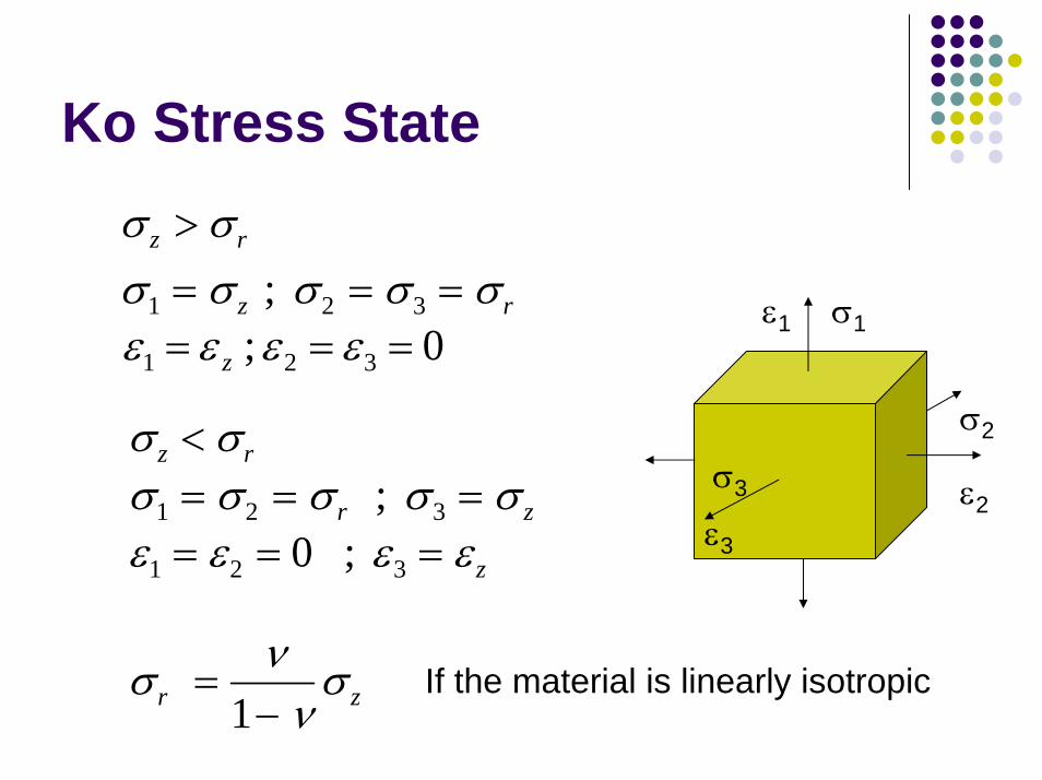
Ko Stress State σ σz r> σ σ σ σ σ1 2 3= = =z r ;
0 ; 321 === εεεε z
σ σz r< σ σ σ σ σ1 2 3= = =r z ;
σ1ε1
σ2
σ3 ε2ε3ε ε ε ε1 2 30= = =; z
σ ννσr z =
−1If the material is linearly isotropic
ε2 0=
ε2 0= − ≠ur
σ σ1 = z
σ σ σ2 3= = r ε ε ε2 3= = r
σ σ2 3 0= =σ σ1 = z ε ε ε2 3= = r
σ σ1 = z ε ε2 3 0= =
σ σ σ2 3= = r
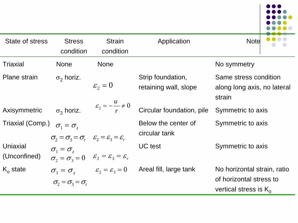
No horizontal strain, ratio of horizontal stress to vertical stress is K0
Areal fill, large tankKo state
Symmetric to axisUC testUniaxial(Unconfined)
Symmetric to axisBelow the center of circular tank
Triaxial (Comp.)
Symmetric to axisCircular foundation, pileσ2 horiz.Axisymmetric
Same stress condition along long axis, no lateral strain
Strip foundation, retaining wall, slope
σ2 horiz.Plane strain
No symmetryNoneNoneTriaxial
NoteApplicationStrain condition
Stress condition
State of stress
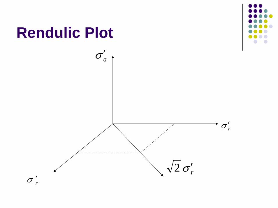
Rendulic Plotaσ ′
rσ ′
2 rσ ′ rσ ′
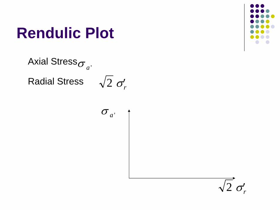
Rendulic PlotAxial Stress
'aσRadial Stress 2 ′σr
'aσ
2 ′σr
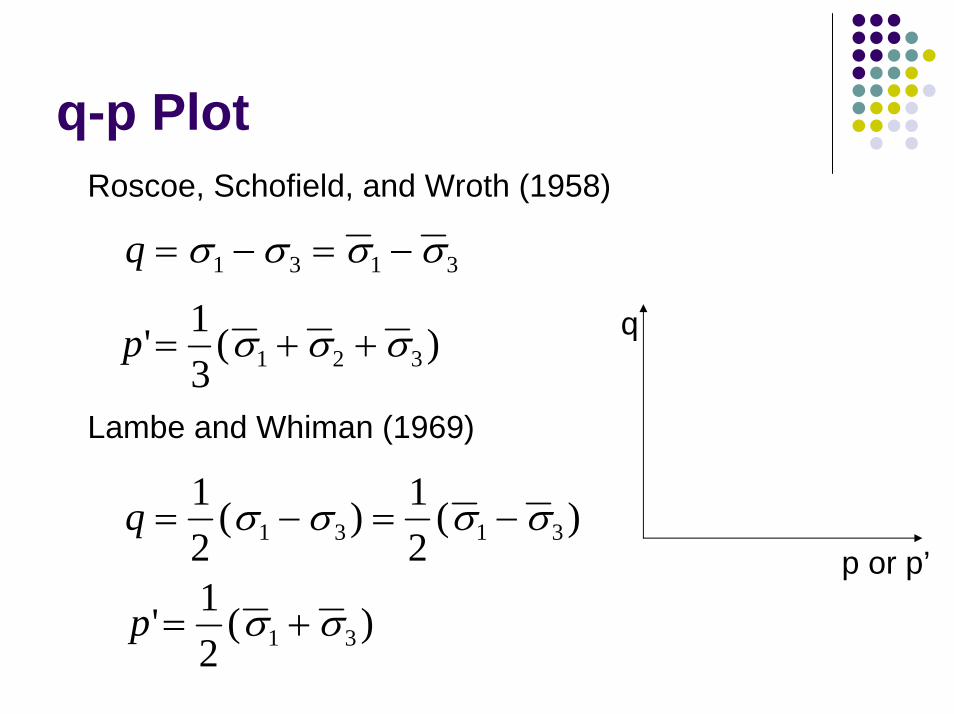
q-p Plot Roscoe, Schofield, and Wroth (1958)
q = − = −σ σ σ σ1 3 1 3
p' ( )= + +1 σ σ σ q3 1 2 3
Lambe and Whiman (1969)
q = − = −12
121 3 1 3( ) ( )σ σ σ σ
p or p’
p' ( )= +12 1 3σ σ
τ - σ Plot
τ
σ or σ’
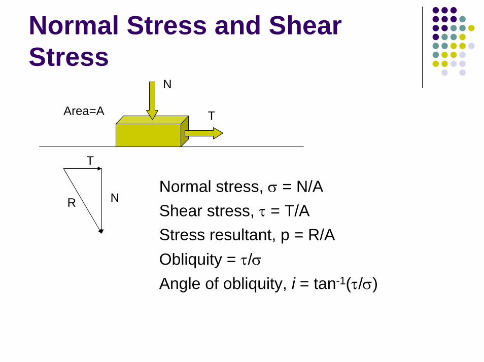
Normal Stress and Shear Stress
N
Area=A T
T
RNormal stress, σ = N/AShear stress, τ = T/AStress resultant, p = R/AObliquity = τ/σAngle of obliquity, i = tan-1(τ/σ)
N
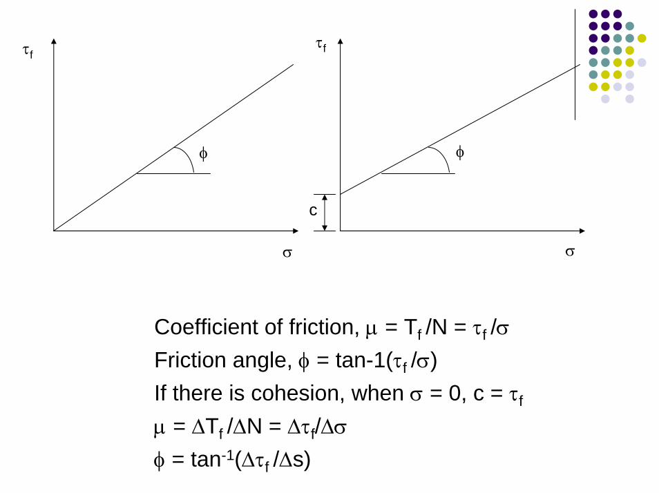
τfτf
Coefficient of friction, µ = Tf /N = τf /σFriction angle, φ = tan-1(τf /σ)If there is cohesion, when σ = 0, c = τf
µ = ∆Tf /∆N = ∆τf/∆σφ = tan-1(∆τf /∆s)
φ φ
c
σσ
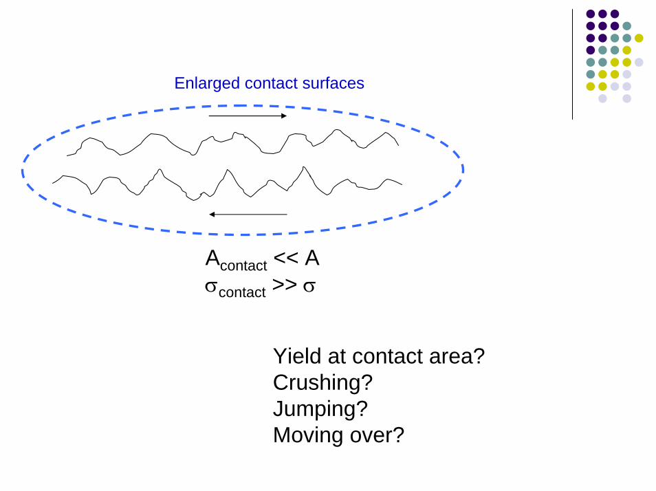
Enlarged contact surfaces
Acontact << Aσcontact >> σ
Yield at contact area?Crushing?Jumping?Moving over?

Ideal Shear Strength Test
Independent control of stress and strain in each directionDirection of principal stressRate of stress or strain applicationUniform distribution of applied stressControl over pore (air or water) pressure
Parameters Obtained
Shear strength parametersPore pressure parametersDeformation parameters
Laboratory Shear Strength Tests
Direct shear testRing shearSimple shear, direct simple shear
Unconfined compression testTriaxial test
CompressionExtension
Plane strain test seldomDynamic strength tests
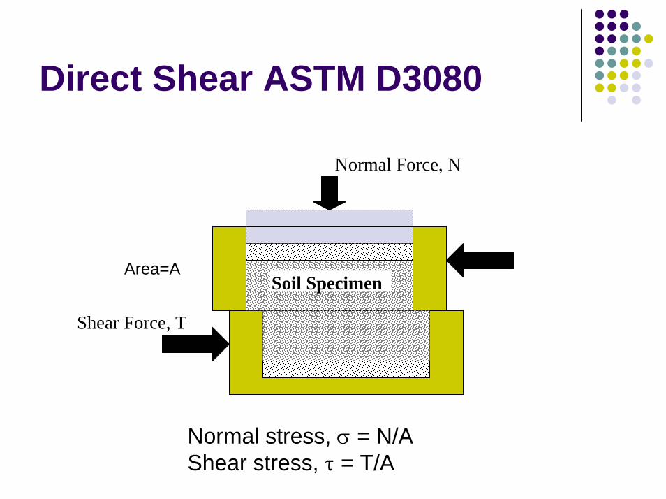
Direct Shear ASTM D3080
Normal Force, N
Shear Force, T
Soil SpecimenArea=A
Normal stress, σ = N/AShear stress, τ = T/A
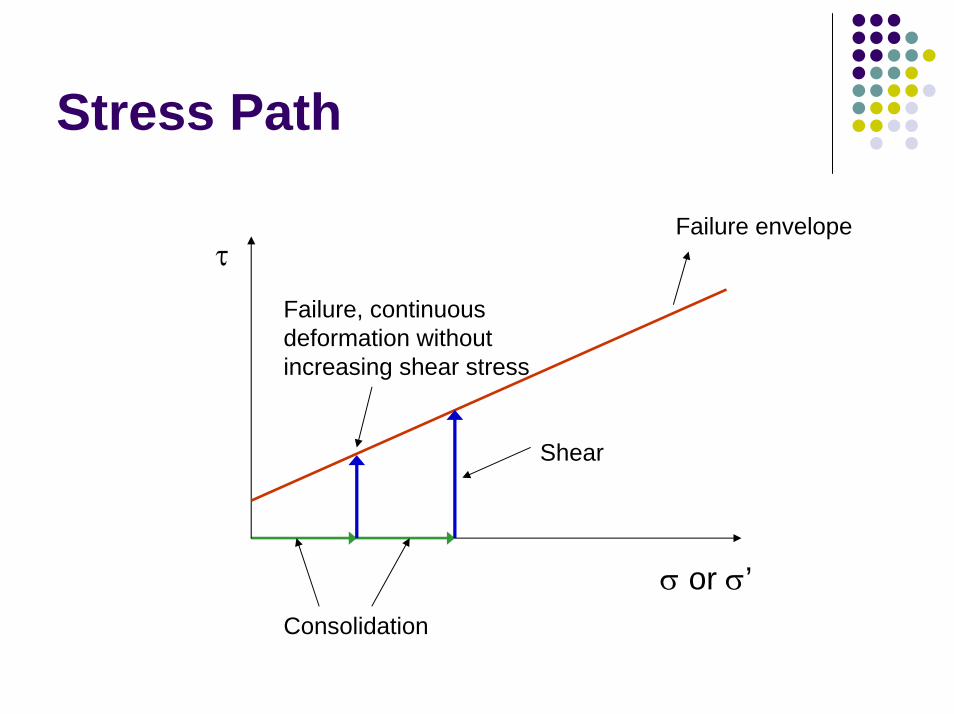
Stress Path
Failure envelopeτ
Shear
Failure, continuous deformation without increasing shear stress
σ or σ’Consolidation
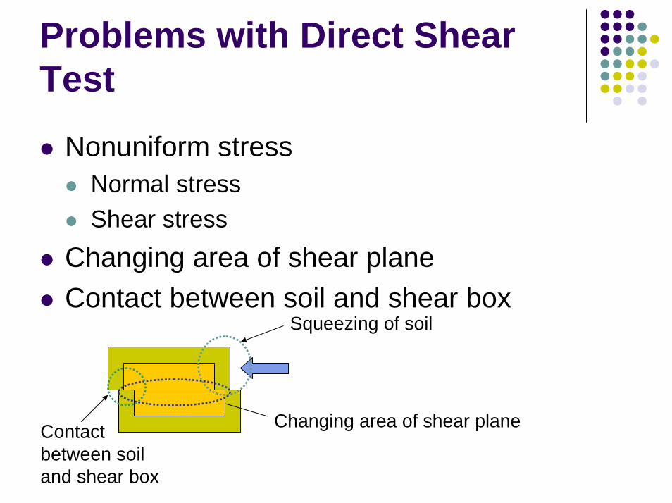
Problems with Direct Shear Test
Nonuniform stressNormal stressShear stress
Changing area of shear planeContact between soil and shear box
Squeezing of soil
Contact between soil and shear box
Changing area of shear plane
Direct Shear
AdvantagesEasy to performLow costA lot of experience
DrawbackSmall-size specimensLimited shear displacementForced failure plane
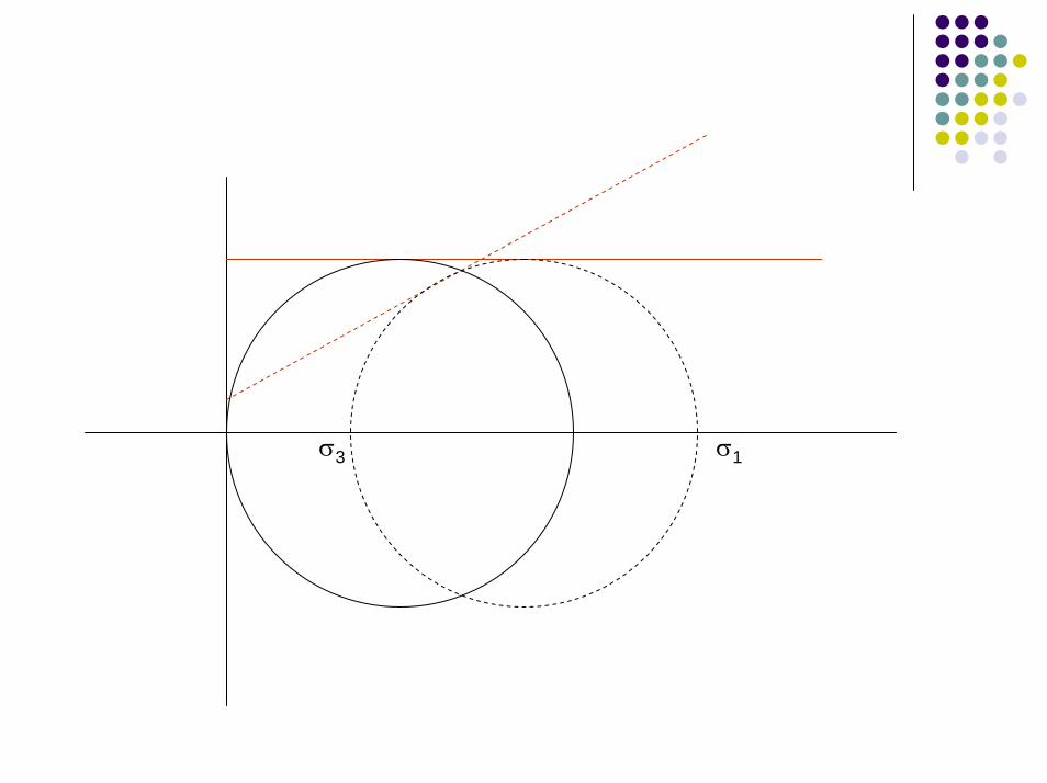
σ σ
poleτ
σ3 1
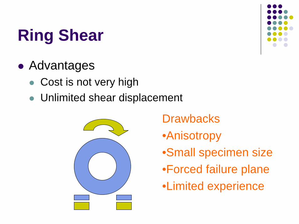
Ring Shear
AdvantagesCost is not very highUnlimited shear displacement
Drawbacks•Anisotropy•Small specimen size•Forced failure plane•Limited experience
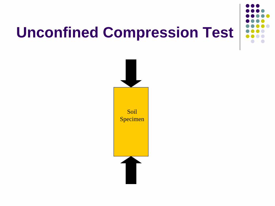
Unconfined Compression Test
Soil Specimen
σ3 σ1
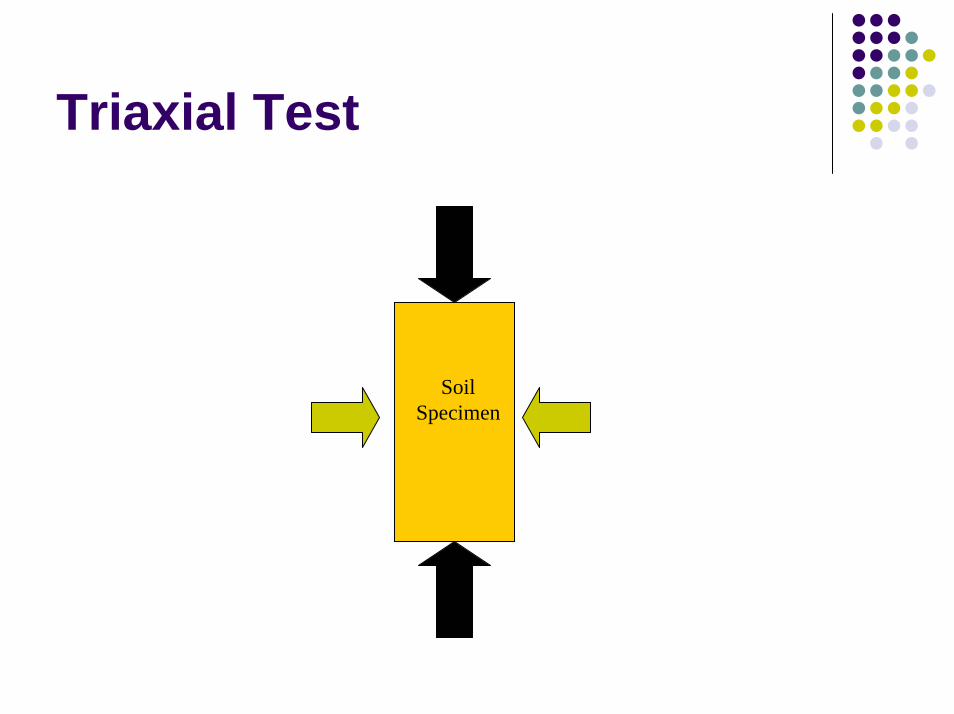
Triaxial Test
Soil Specimen
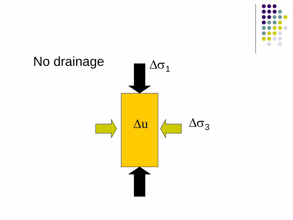
No drainage
∆u
∆σ1
∆σ3
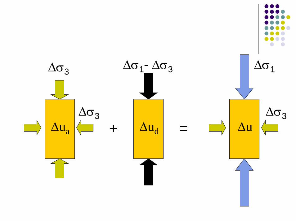
∆u
∆σ1∆σ1- ∆σ3∆σ3
∆ud∆ua
∆σ3 ∆σ3
+ =
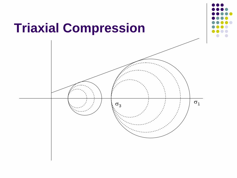
Triaxial Compression
σ3σ1
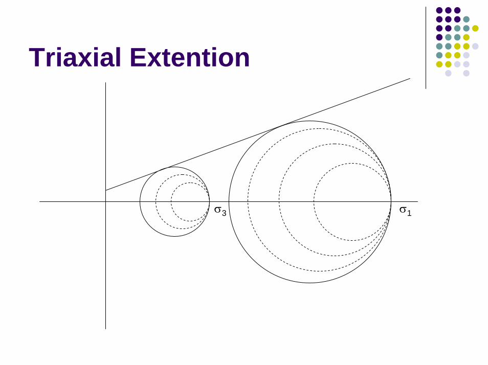
Triaxial Extention
σ3 σ1
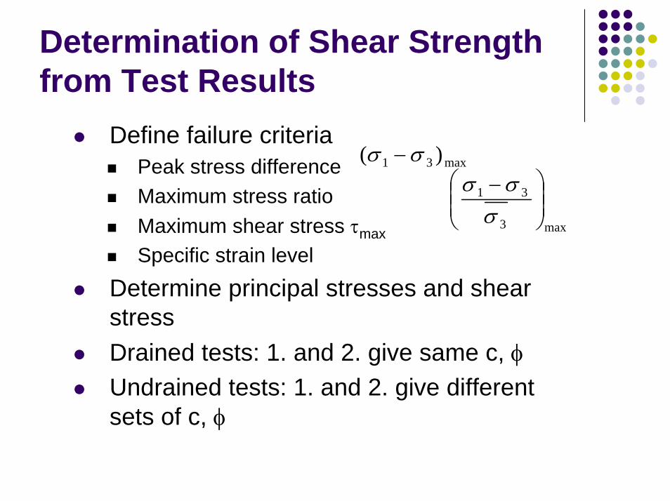
Determination of Shear Strength from Test Results
Define failure criteriaPeak stress differenceMaximum stress ratioMaximum shear stress τmax
Specific strain levelDetermine principal stresses and shear stressDrained tests: 1. and 2. give same c, φUndrained tests: 1. and 2. give different sets of c, φ
max31 )( σσ −
max3
31
−σσσ
Selection of failure criteria depends on:Testing conditionField condition (Drained vs. Undrained)Method of analysis (Total stress vs. Effective stress)
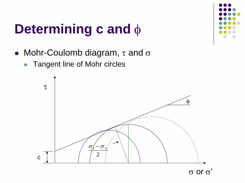
Determining c and φMohr-Coulomb diagram, τ and σ
Tangent line of Mohr circles
τ
231 σσ −
φ
c
σ or σ’

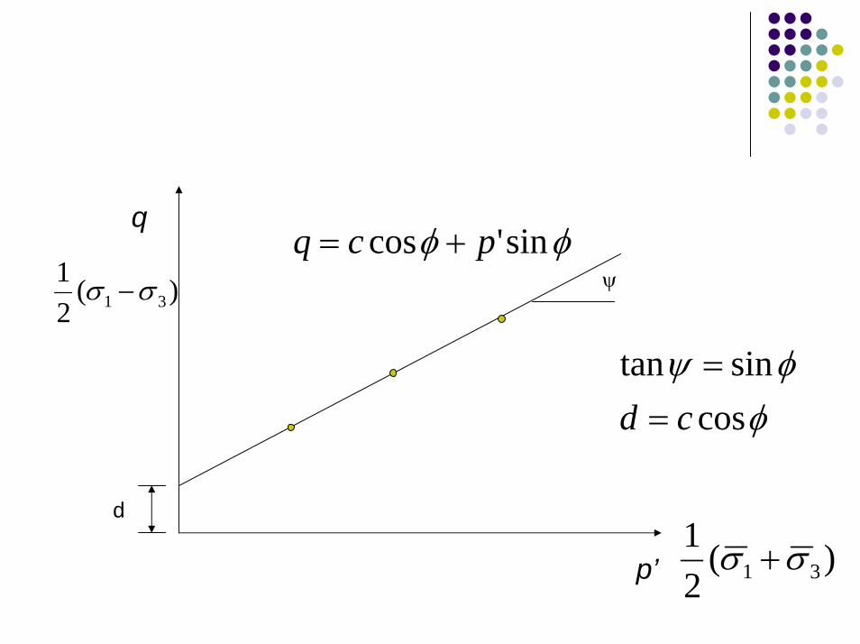
q-p’ plotLinear regression of (q’, p) sets
q = − = −12
121 3 1 3( ) ( )σ σ σ σ
p' ( )= +12 1 3σ σ
q
)(21
31 σσ −
φφ sin'cos pcq +=ψ
φφψ
cossintan
cd ==
d
)(21
31 σσ +p’
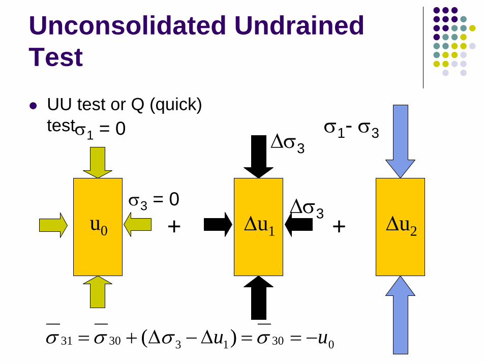
Unconsolidated UndrainedTest
UU test or Q (quick) testσ1 = 0
+ +∆u1u0
σ3 = 0 ∆σ3
∆σ3
030133031 )( uu −==∆−∆+= σσσσ
σ1- σ3
∆u2
Reason for the Confining Stress
More similar to actual field condition where all around pressure existsIncrease the degree of saturationCan make the fissures (formed during the extrusion of tube samples) in the specimens close up
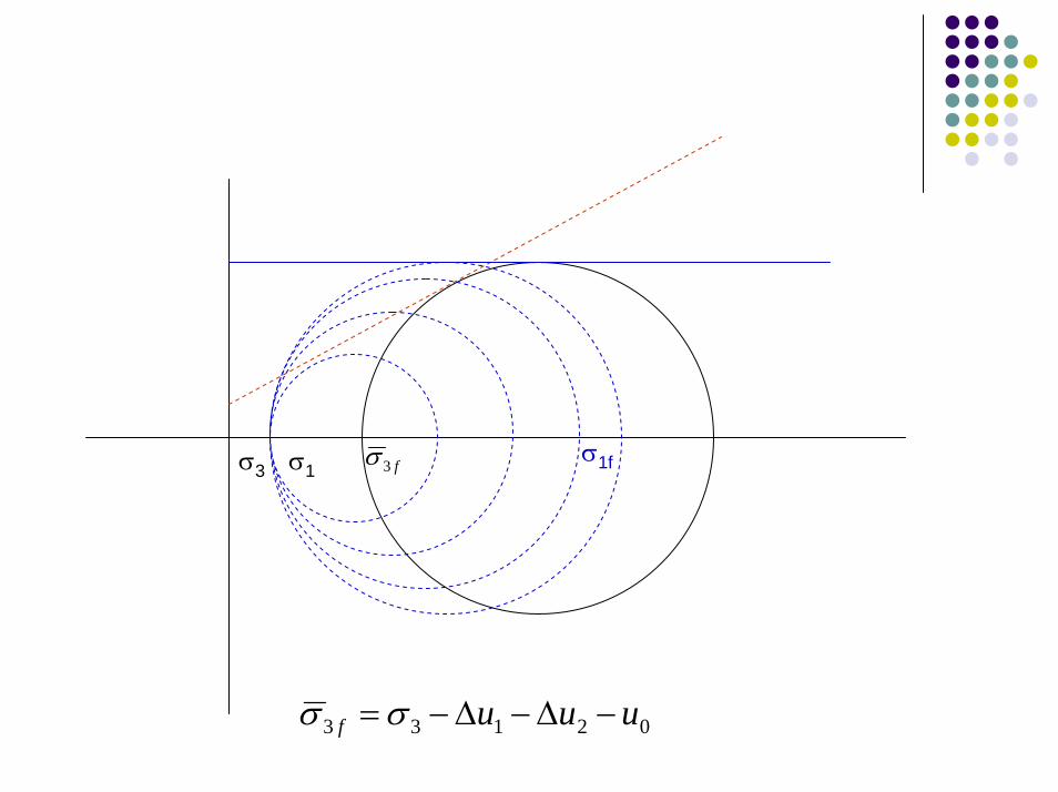
σ1σ1ff3σσ3
02133 uuuf −∆−∆−=σσ
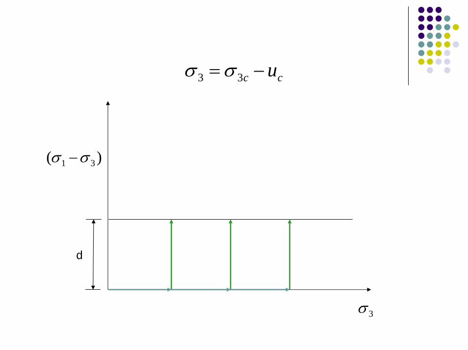
cc u−= 33 σσ
)( 31 σσ −
d
3σ
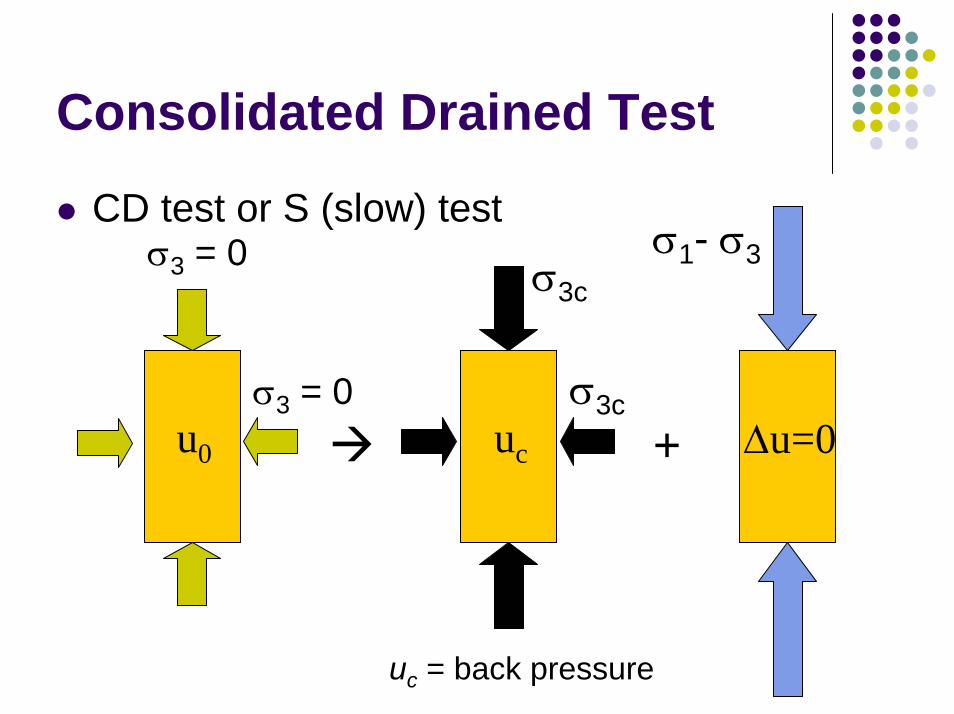
Consolidated Drained Test
CD test or S (slow) testσ1- σ3σ3 = 0
+ ∆u=0ucu0
σ3 = 0 σ3c
σ3c
uc = back pressure
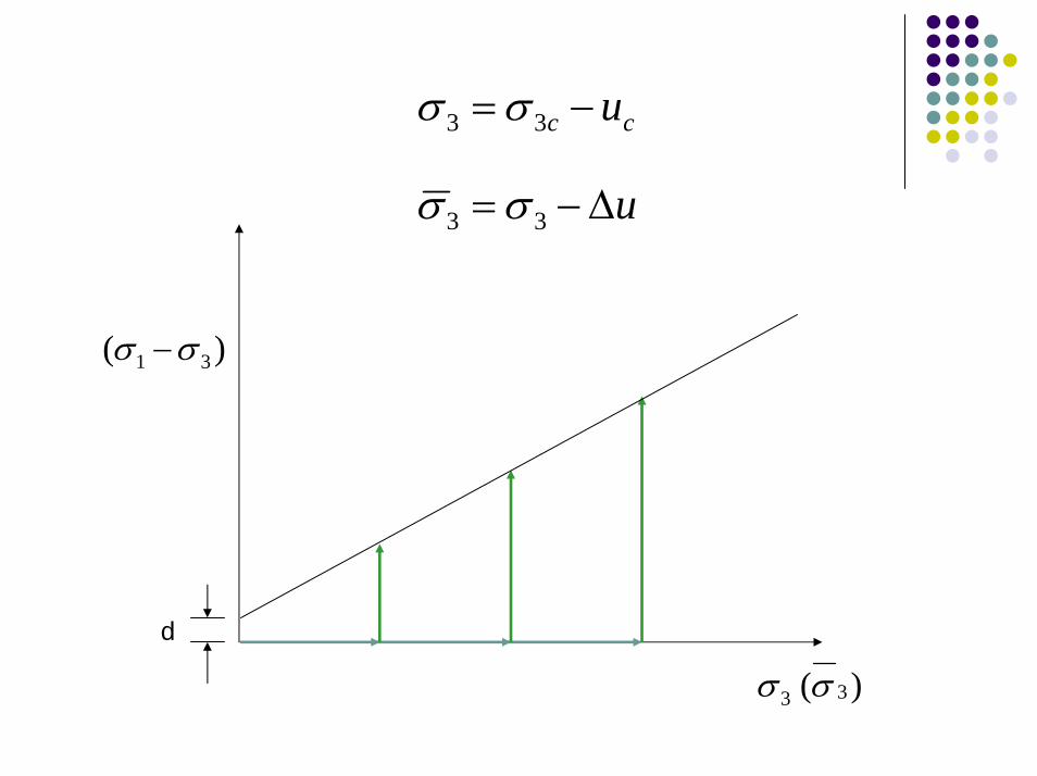
cc u−= 33 σσ
u∆−= 33 σσ
)( 31 σσ −
d
)( 33 σσ
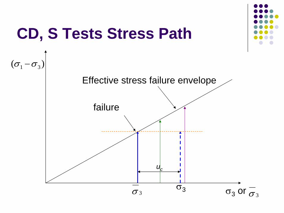
CD, S Tests Stress Path
)( 31 σσ −
Effective stress failure envelope
failure
σ33σ
uc
σ3 or σ 3
σ1
σ3
σ1f
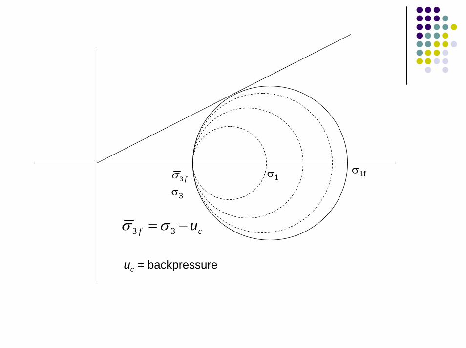
cf u−= 33 σσ
f3σ
uc = backpressure
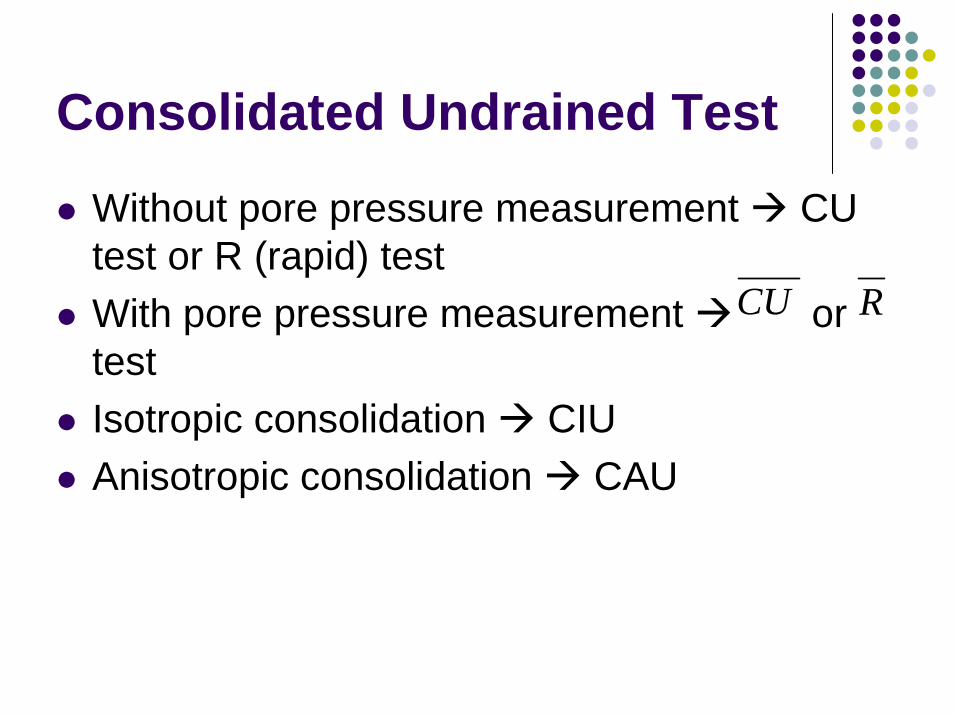
Consolidated Undrained Test
Without pore pressure measurement CU test or R (rapid) testWith pore pressure measurement or testIsotropic consolidation CIUAnisotropic consolidation CAU
CU R

∆u3
σ1- σ3
∆u2
∆σ3+
∆σ3σ3 = 0
uc
σ3c
u0 +σ3cσ3 = 0
uc = back pressure
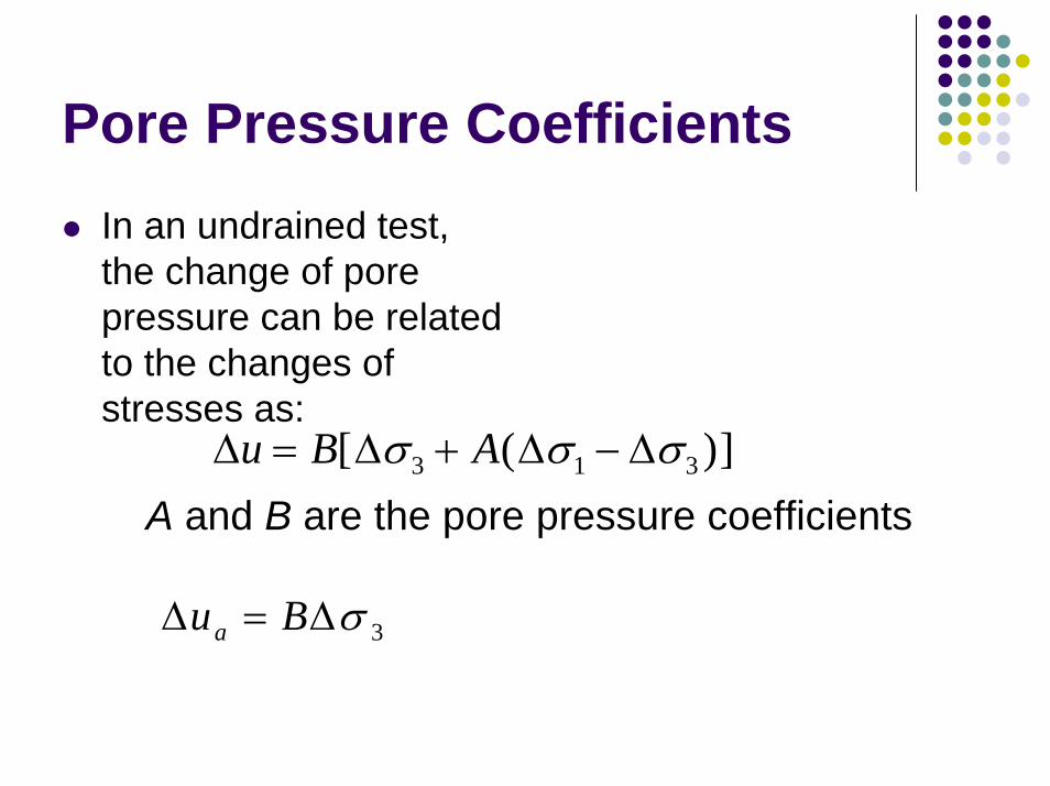
Pore Pressure CoefficientsIn an undrained test, the change of pore pressure can be related to the changes of stresses as:
∆ ∆ ∆ ∆u B A= + −[ ( )]σ σ σ3 1 3
A and B are the pore pressure coefficients
3σ∆=∆ Bua
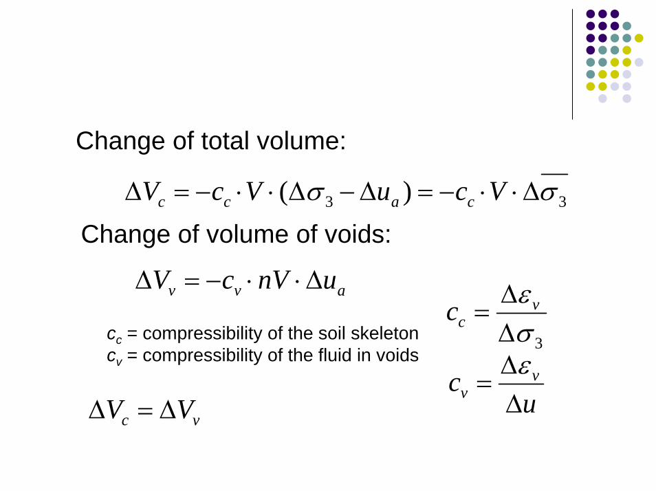
Change of total volume:
33 )( σσ ∆⋅⋅−=∆−∆⋅⋅−=∆ VcuVcV cacc
Change of volume of voids:
avv unVcV ∆⋅⋅−=∆
3σε
∆∆
= vcc
uc v
v ∆∆
=ε
cc = compressibility of the soil skeletoncv = compressibility of the fluid in voids
vc VV ∆=∆

c
v
ccnB⋅
+=
1
1
For saturated soils, if cc >> cv, B 1(soil skeleton is much more compressible than the fluid)
For very stiff clays whose cc is also very small, Bmay not be close to 1 even if the soil is almost saturated
→
⋅ 0c
v
ccn
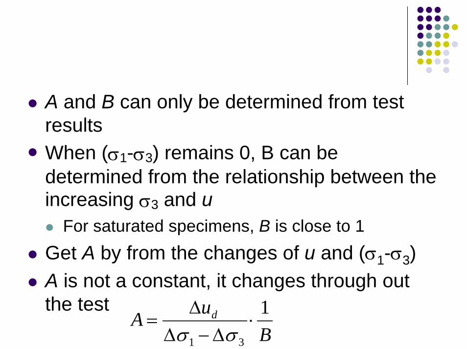
A and B can only be determined from test resultsWhen (σ1-σ3) remains 0, B can be determined from the relationship between the increasing σ3 and u
For saturated specimens, B is close to 1Get A by from the changes of u and (σ1-σ3)A is not a constant, it changes through out the test
BuA d 1
31
⋅∆−∆
∆=
σσ
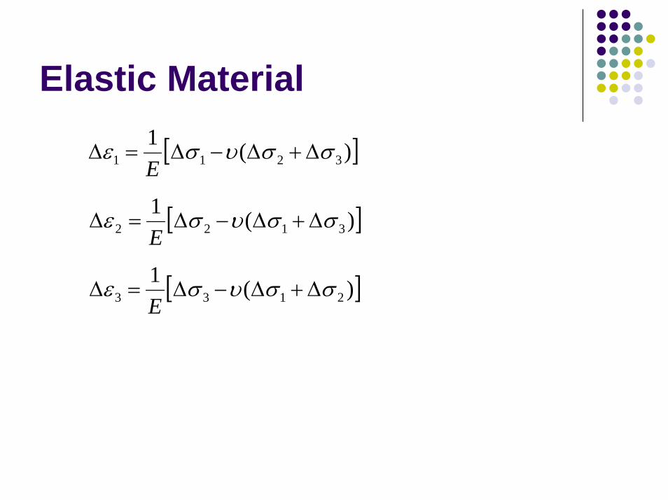
Elastic Material
[ ])(13211 σσυσε ∆+∆−∆=∆
E
[ ])(13122 σσυσε ∆+∆−∆=∆
E
[ ])(12133 σσυσε ∆+∆−∆=∆
E
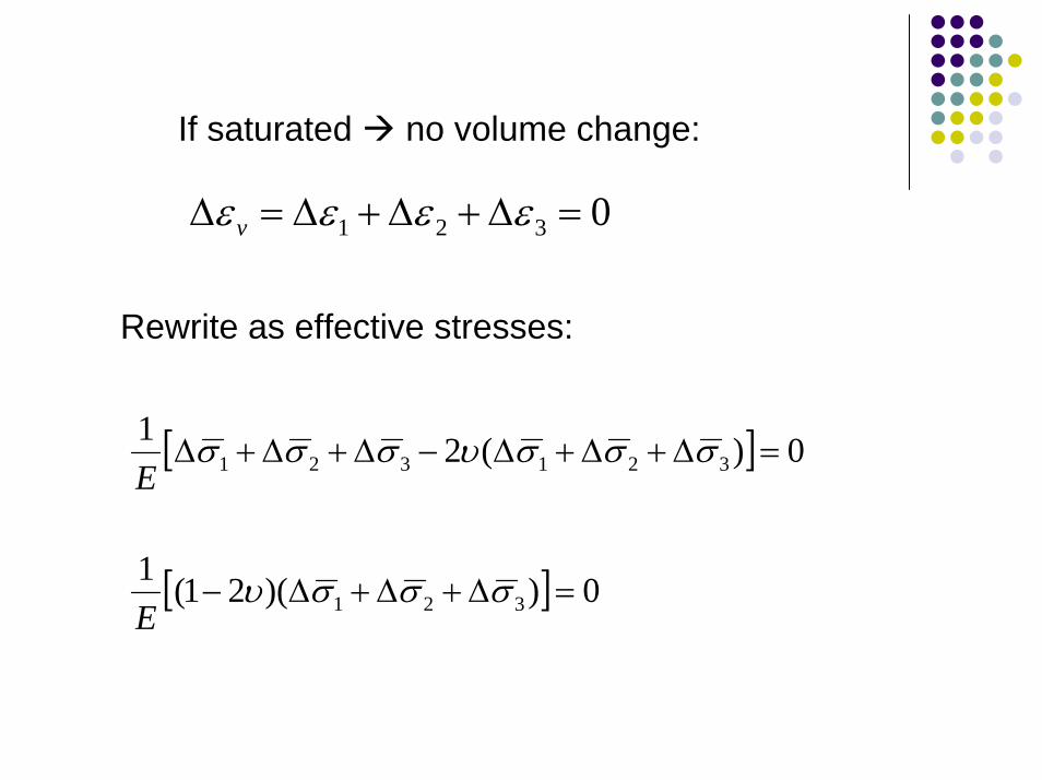
If saturated no volume change:
0321 =∆+∆+∆=∆ εεεε v
Rewrite as effective stresses:
[ ] 0)(21321321 =∆+∆+∆−∆+∆+∆ σσσυσσσ
E
[ ] 0))(21(1321 =∆+∆+∆− σσσυ
E
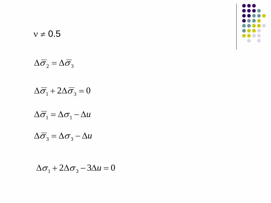
ν ≠ 0.5
32 σσ ∆=∆
02 31 =∆+∆ σσ
u∆−∆=∆ 11 σσ
u∆−∆=∆ 33 σσ
032 31 =∆−∆+∆ uσσ
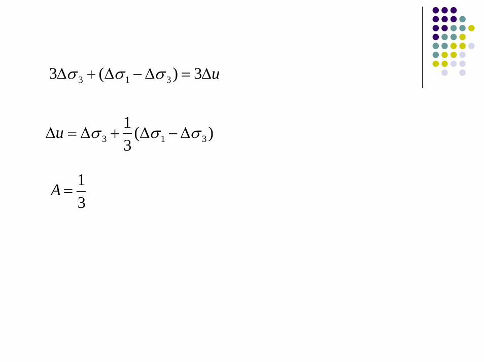
u∆=∆−∆+∆ 3)(3 313 σσσ
)(31
313 σσσ ∆−∆+∆=∆u
31
=A
Use B to check the saturation of soil specimens
Incremental increase of ∆σ3 check the increase of ∆u compute BIf B is close to 1, the specimen is near saturation
Although B is an indication of the degree of saturation, there is no way of knowing the degree of saturation from values of B
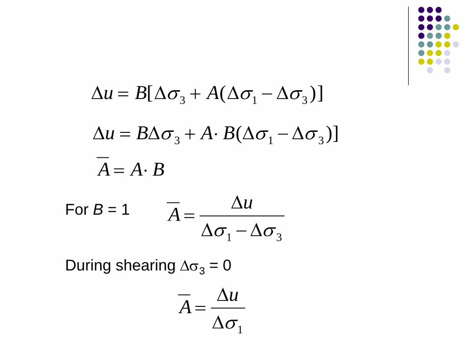
∆ ∆ ∆ ∆u B A= + −[ ( )]σ σ σ3 1 3
)]( 313 σσσ ∆−∆⋅+∆=∆ BABu
BAA ⋅=
31 σσ ∆−∆∆
=uAFor B = 1
During shearing ∆σ3 = 0
1σ∆∆
=uA
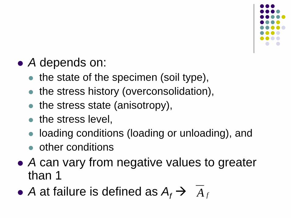
A depends on:the state of the specimen (soil type),the stress history (overconsolidation),the stress state (anisotropy),the stress level,loading conditions (loading or unloading), and other conditions
A can vary from negative values to greater than 1A at failure is defined as Af fA
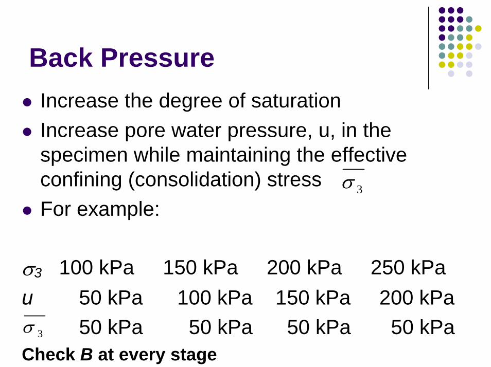
Back PressureIncrease the degree of saturationIncrease pore water pressure, u, in the specimen while maintaining the effective confining (consolidation) stressFor example:
σ3 100 kPa 150 kPa 200 kPa 250 kPau 50 kPa 100 kPa 150 kPa 200 kPa
50 kPa 50 kPa 50 kPa 50 kPaCheck B at every stage
3σ
3σ
How Does Backpressure Works?
Elevated pore water pressure can squeeze on the trapped air bubbles and make them decrease in sizeElevated pore water pressure would make the trapped air more likely to dissolve in water
Some would apply a small hydraulic gradient to help flush out the air during the saturation process
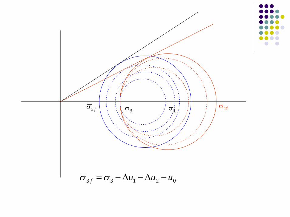
σ1σ3f3σ σ1f
02133 uuuf −∆−∆−=σσ
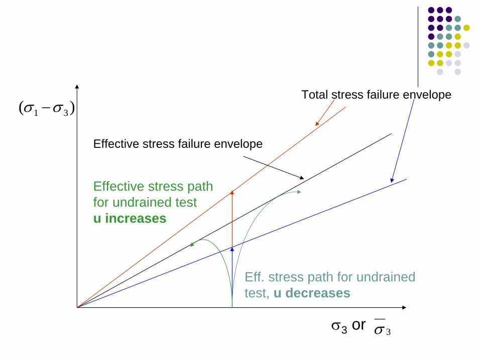
Eff. stress path for undrainedtest, u decreases
Effective stress path for undrained testu increases
Effective stress failure envelope
)( 31 σσ −Total stress failure envelope
σ3 or 3σ
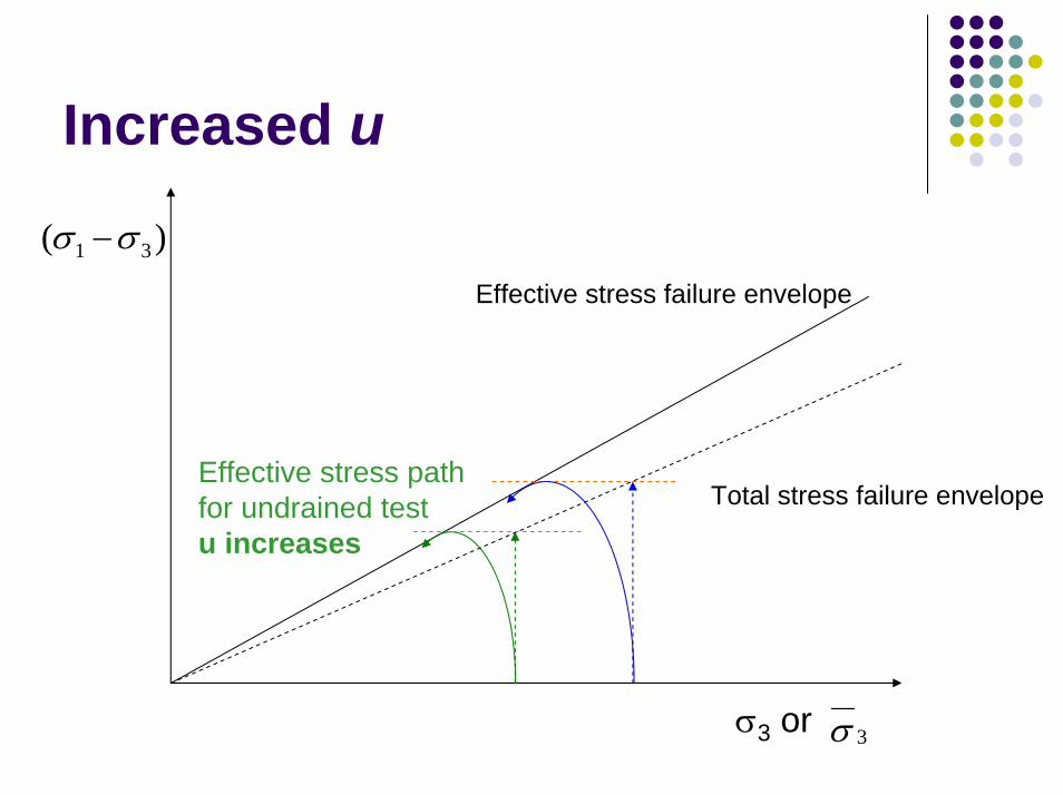
Increased u
)( 31 σσ −
Effective stress path for undrained testu increases
Effective stress failure envelope
Total stress failure envelope
σ3 or 3σ
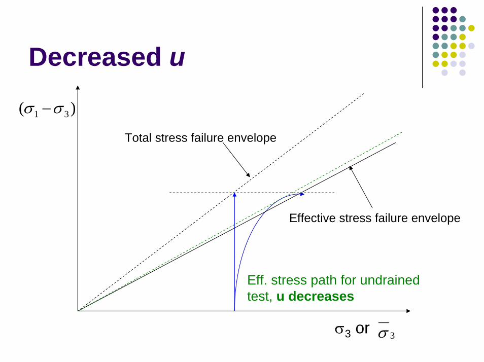
Decreased u
Eff. stress path for undrainedtest, u decreases
Effective stress failure envelope
)( 31 σσ −
Total stress failure envelope
σ3 or 3σ
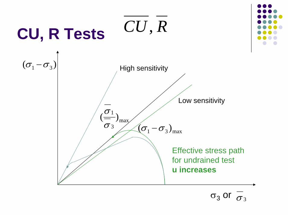
RCU ,CU, R Tests
Effective stress path for undrained testu increases
)( 31 σσ −
max31 )( σσ −max
3
1 )(σσ
Low sensitivity
High sensitivity
σ3 or 3σ
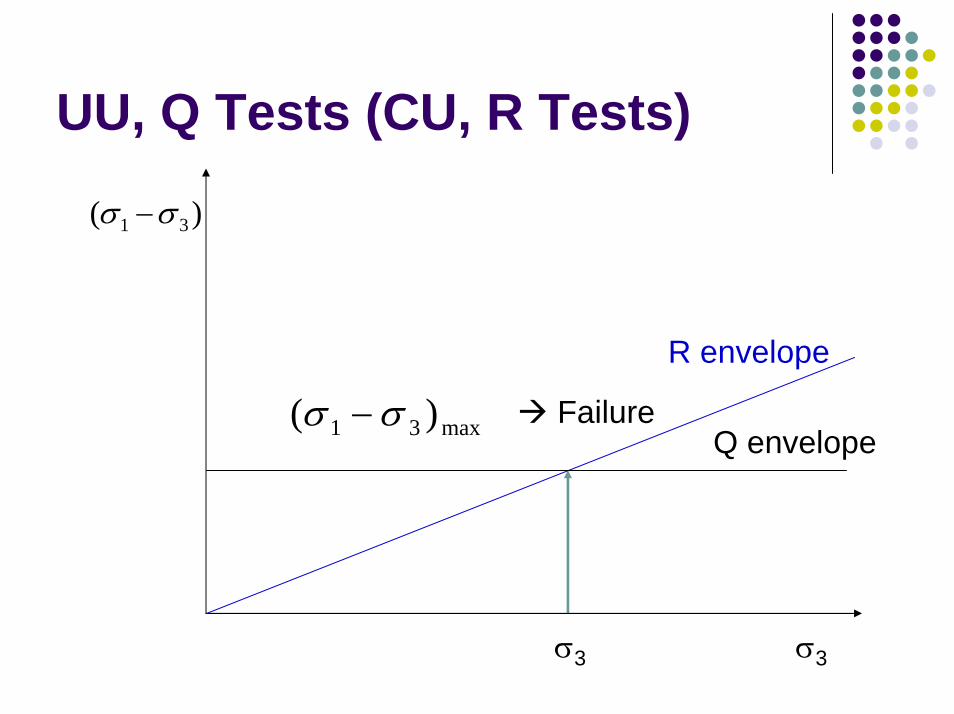
UU, Q Tests (CU, R Tests)
)( 31 σσ −
Q envelopemax31 )( σσ −
R envelope
Failure
σ3 σ3
Energy Corrections
Direct shear testsTriaxial tests
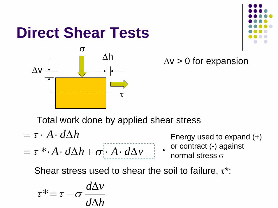
Direct Shear Testsσ
vdAhdAhdA
∆⋅⋅+∆⋅⋅=∆⋅⋅=
σττ
*
∆h ∆v > 0 for expansion
τ
∆v
Total work done by applied shear stress
Energy used to expand (+) or contract (-) against normal stress σ
Shear stress used to shear the soil to failure, τ*:
hdvd
∆∆
−= σττ*
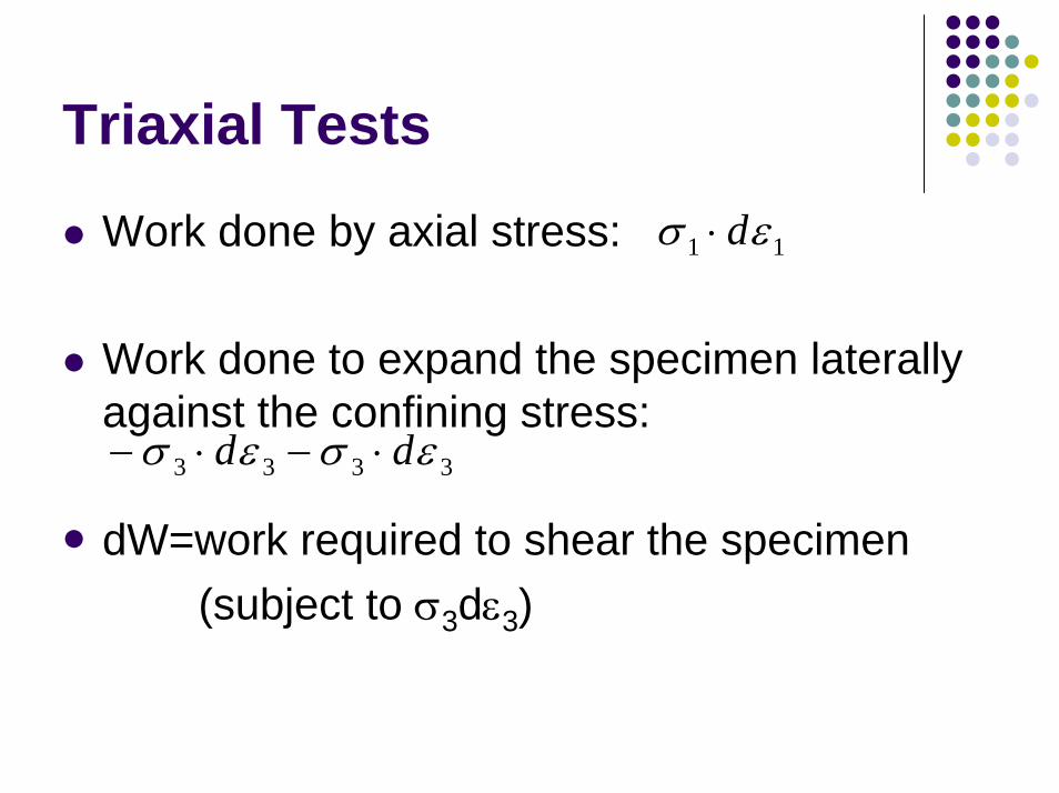
Triaxial Tests
Work done by axial stress:
Work done to expand the specimen laterally against the confining stress:
dW=work required to shear the specimen(subject to σ3dε3)
3333 εσεσ dd ⋅−⋅−
11 εσ d⋅
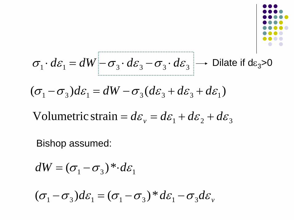
333311 εσεσεσ dddWd ⋅−⋅−=⋅ Dilate if dε3>0
)()( 1333131 εεεσεσσ ddddWd ++−=−
321strain Volumetric εεεε dddd v ++==
Bishop assumed:
131 *)( εσσ ddW ⋅−=
vddd εσεσσεσσ 3131131 *)()( −−=−
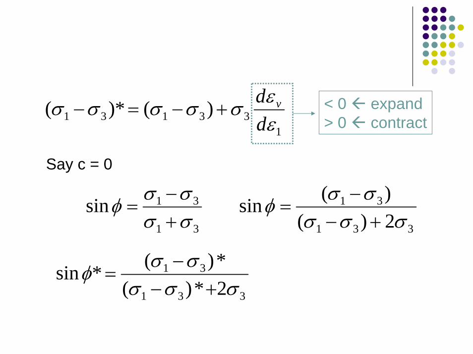
133131 )()*(
εεσσσσσ
dd v+−=− < 0 expand
> 0 contract
Say c = 0
331
31
2)()(sinσσσ
σσφ+−
−=
31
31sinσσσσφ
+−
=
331
31
2*)(*)(*sinσσσ
σσφ+−
−=
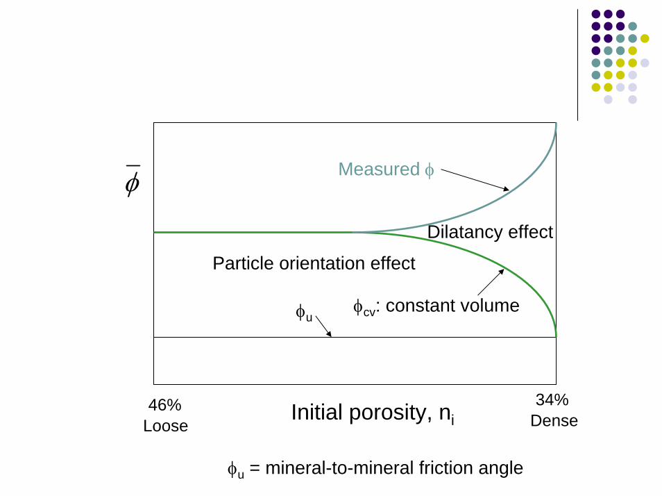
Measured φ
Particle orientation effect
Dilatancy effect
φuφcv: constant volume
φ
34%46% Initial porosity, ni DenseLoose
φu = mineral-to-mineral friction angle
1
)1(*sin
3
1
3
1
+
−−=
σσ
εε
σσ
φ a
v
ddBishop
)1(
)1(*sin
3
1
3
1
a
v
a
v
dddd
εε
σσ
εε
σσ
φ−+
−−=
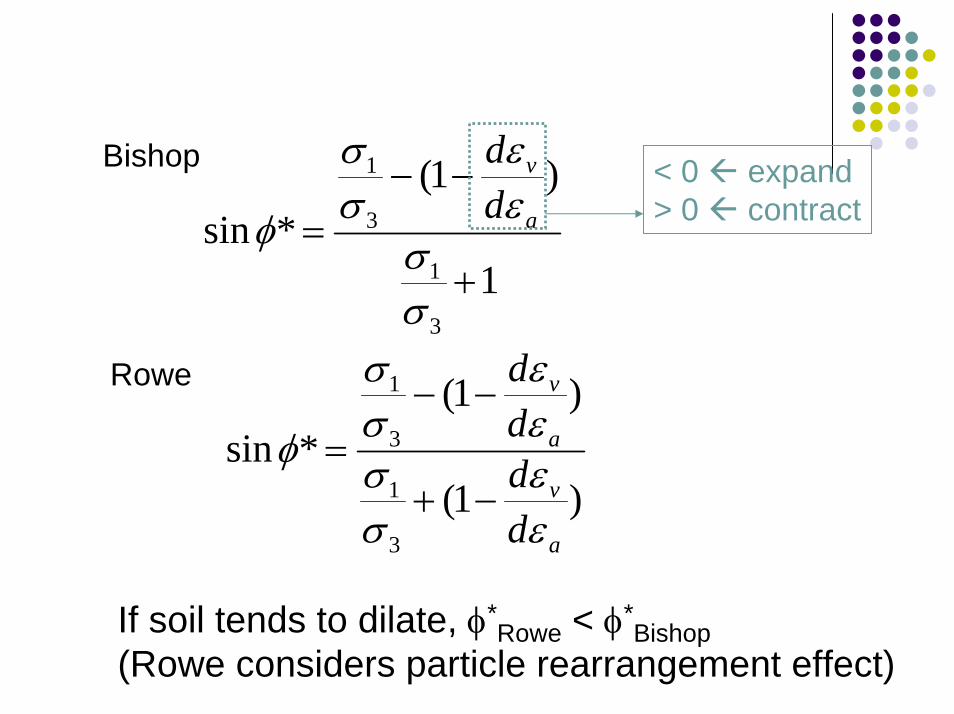
< 0 expand> 0 contract
Rowe
If soil tends to dilate, φ*Rowe < φ*
Bishop(Rowe considers particle rearrangement effect)
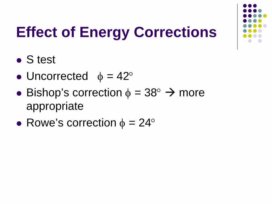
Effect of Energy Corrections
S testUncorrected φ = 42°Bishop’s correction φ = 38° more appropriateRowe’s correction φ = 24°

Effect of Confining Pressure
ffc )( 03
1σ
σφ ==
Pourse and Bell (1971) – sand, Dr=94%
3σ φ0.2 psi 52°10 psi 28.5°
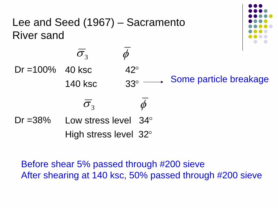
Lee and Seed (1967) – Sacramento River sand
3σ φ40 ksc 42°140 ksc 33°
Dr =100%Some particle breakage
3σ φLow stress level 34°High stress level 32°
Dr =38%
Before shear 5% passed through #200 sieveAfter shearing at 140 ksc, 50% passed through #200 sieve
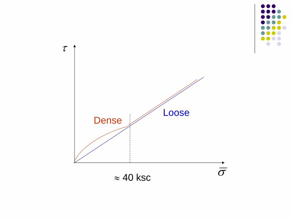
τ
DenseLoose
σ≈ 40 ksc
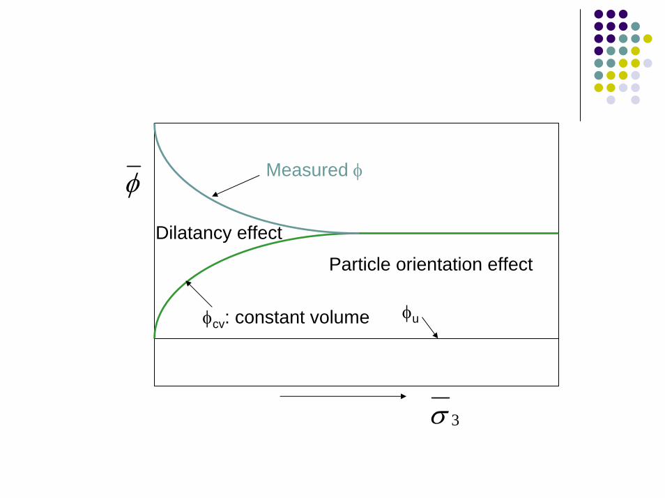
Measured φ
Particle orientation effect
Dilatancy effect
φuφcv: constant volume
φ
3σ
Some Other “Corrections” or “Considerations”
Measured stressMembrane correctionEffect of friction between soil specimen and filter paper/porous disk/cap and pedestal
B valueFlexibility of drainage tubingUse metal tubing
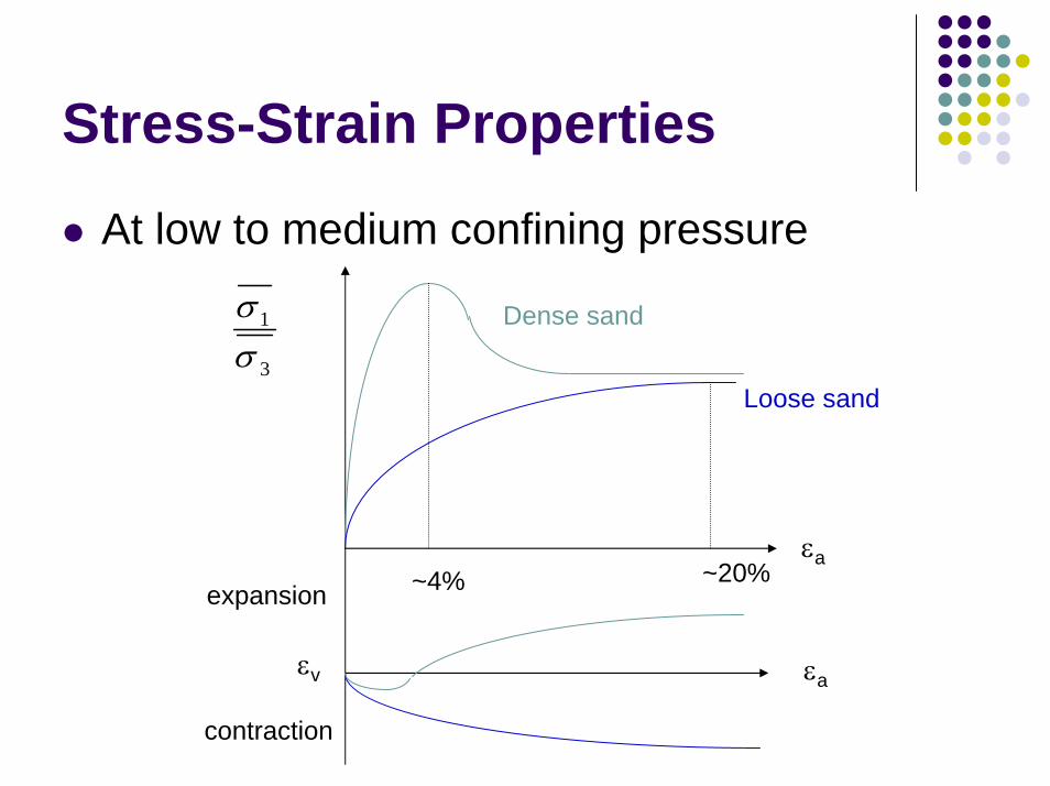
Stress-Strain Properties
At low to medium confining pressure
Dense sand
3
1
σσ
Loose sand
εa~20%~4%expansion
εv εa
contraction
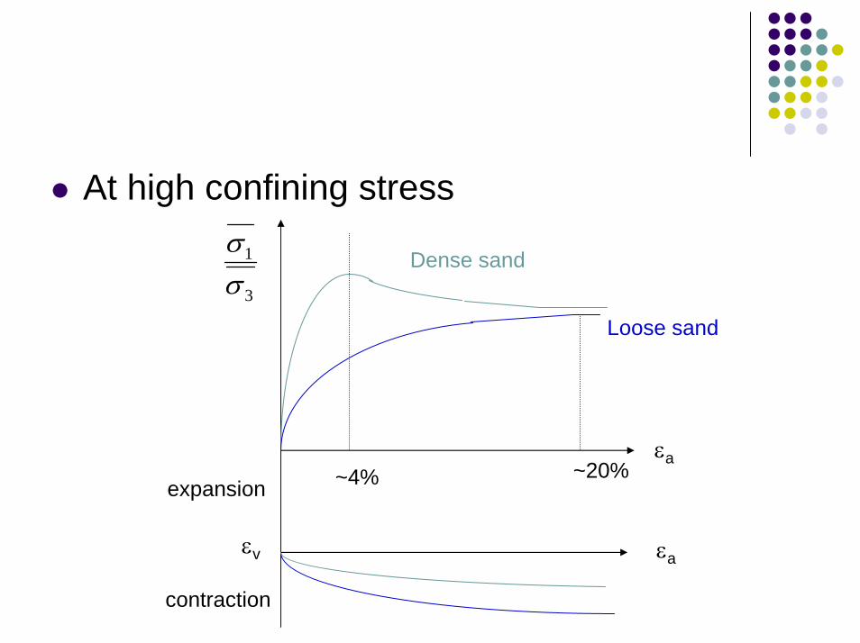
At high confining stress
3
1
σσ
Dense sand
Loose sand
εa~20%~4%expansion
εv εa
contraction
At larger strains dense sand and loose sand tend to have the same void ratio They tend to have the same strength
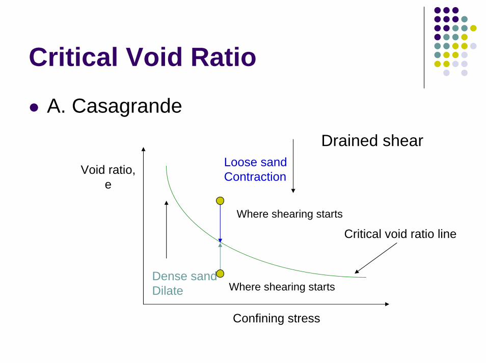
Critical Void Ratio
A. Casagrande
Loose sandContraction
Dense sandDilate
Critical void ratio line
Where shearing starts
Where shearing starts
Drained shear
Void ratio,e
Confining stress
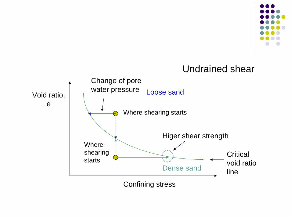
Undrained shear
Loose sand
Where shearing starts
Where shearing starts
Change of pore water pressure
Higer shear strength
Void ratio,e
Critical void ratio lineDense sand
Confining stress
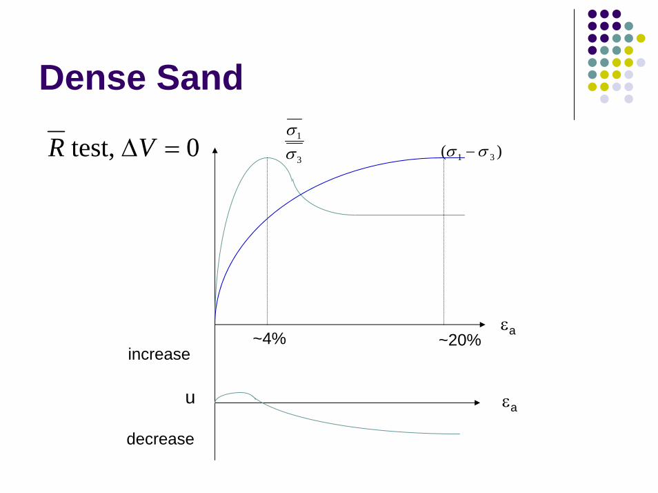
Dense Sand
εa
3
1
σσ
)( 31 σσ −0 test, =∆VR
~4% ~20%increase
u εa
decrease
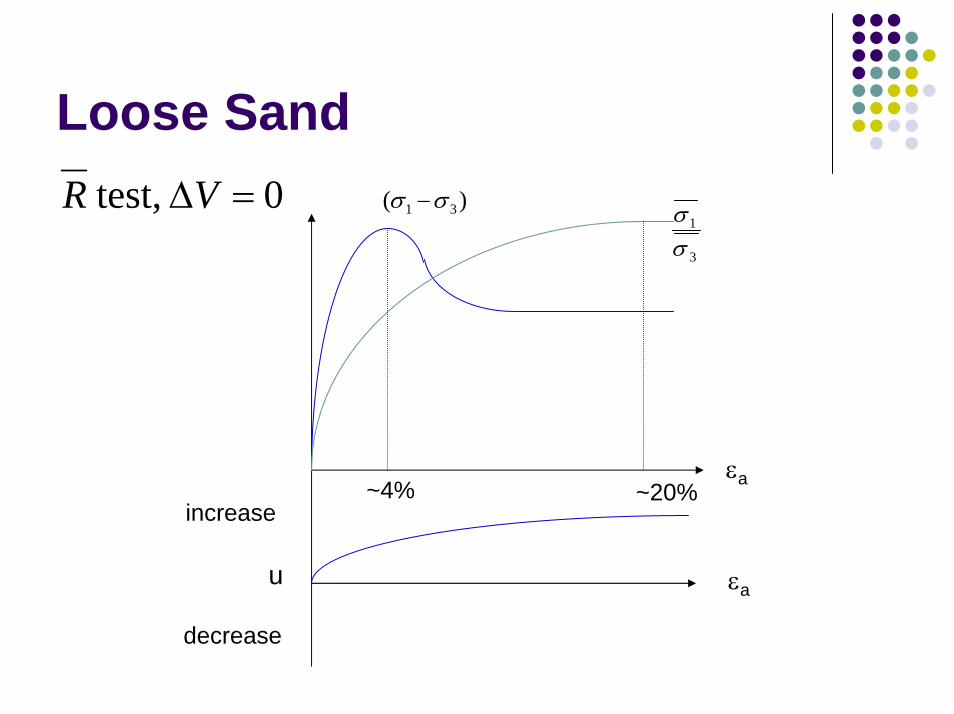
Loose Sand0 test, =∆VR )( 31 σσ −
3
1
σσ
εa~4% ~20%increase
u εa
decrease
For normally consolidated clay, when (σ1-σ3) reaches maximum, its shear strength has not been fully mobilized yet the shear strength is still increasingFor overconsolidated clay, although the shear strength has been fully mobilized, (σ1-σ3)keeps increasing due to the increase of effective confining stress the difference is not as significant as for N.C. clay
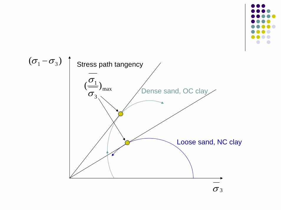
)( 31 σσ −
max3
1 )(σσ
Stress path tangency
Dense sand, OC clay
Loose sand, NC clay
3σ
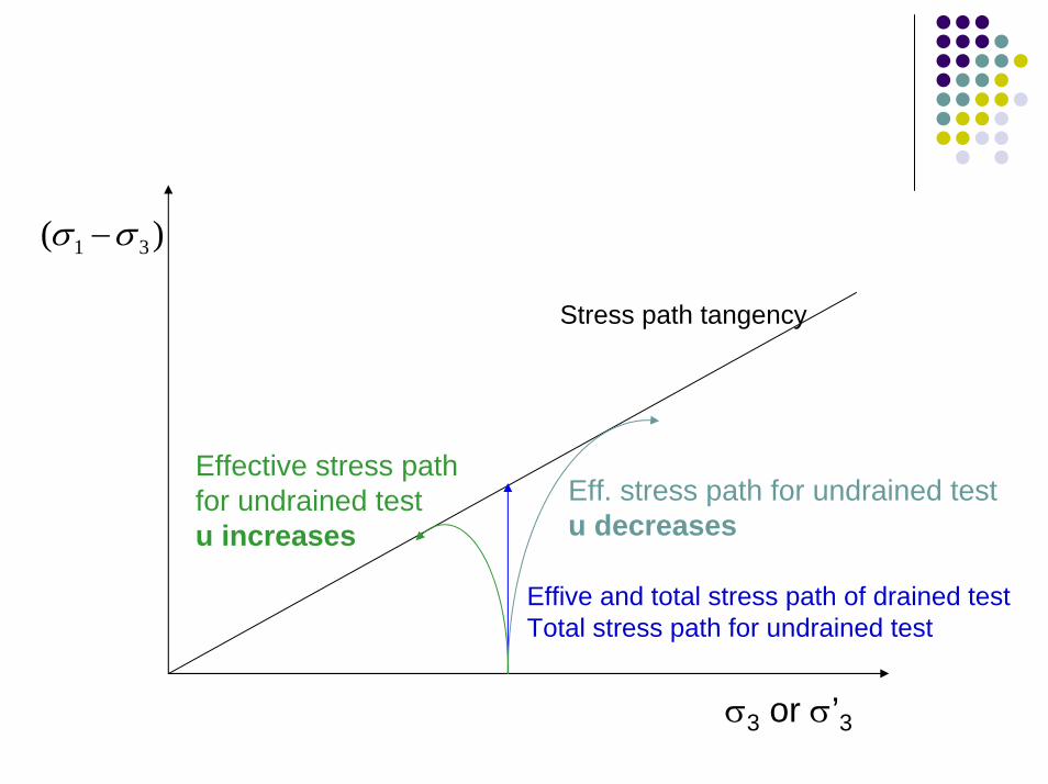
)( 31 σσ −
Effive and total stress path of drained testTotal stress path for undrained test
Eff. stress path for undrained testu decreases
Effective stress path for undrained testu increases
Stress path tangency
σ3 or σ’3
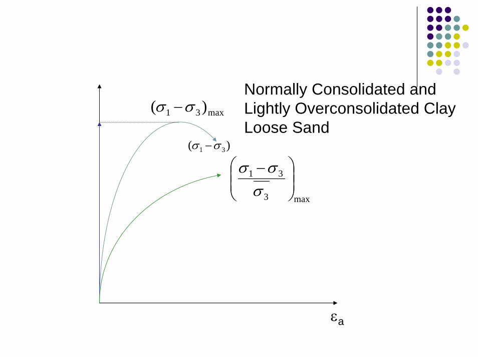
)( 31 σσ −
max3
31
−σσσ
Normally Consolidated and Lightly Overconsolidated ClayLoose Sand
max31 )( σσ −
εa
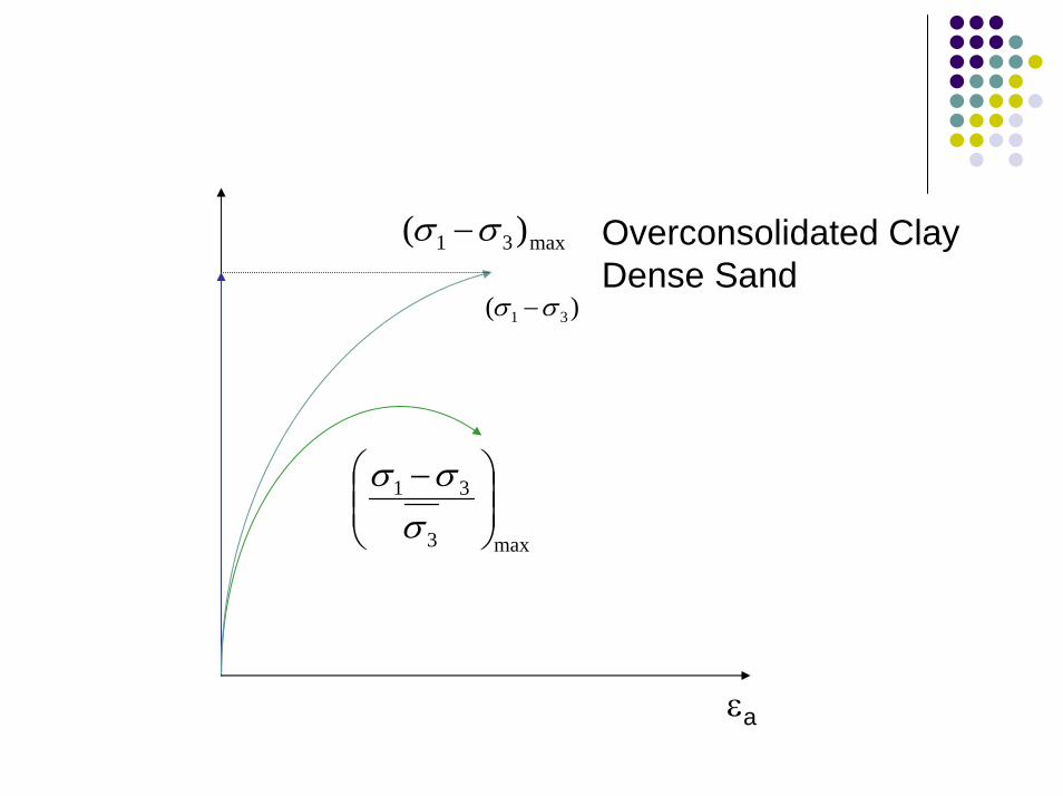
max31 )( σσ − Overconsolidated ClayDense Sand
)( 31 σσ −
max3
31
−σσσ
εa
Steady-State Strength
The steady-state deformation for any mass of particles is that the state in which the mass is continuously deforming at constant volume, constant normal effective stress, constant shear stress, and constant velocity
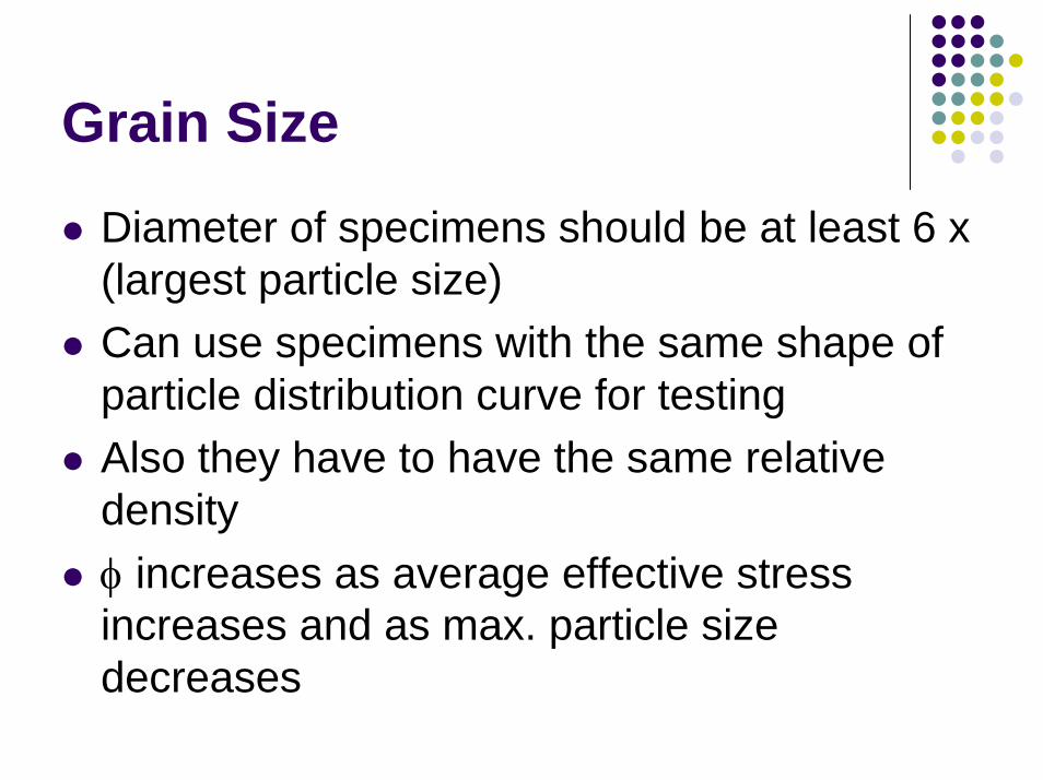
Grain Size
Diameter of specimens should be at least 6 x (largest particle size)Can use specimens with the same shape of particle distribution curve for testingAlso they have to have the same relative densityφ increases as average effective stress increases and as max. particle size decreases
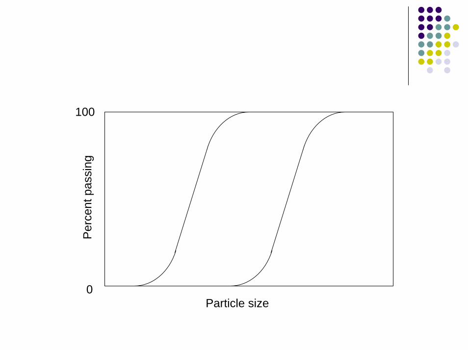
100
Per
cent
pas
sing
0Particle size
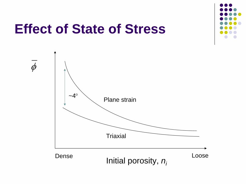
Effect of State of Stress
φ
~4° Plane strain
Triaxial
LooseDense Initial porosity, ni
Direct Shear Test
Direct shear is a “plane strain” test higher friction angleThe stress on the failure plane is not uniform, not all parts reached peak stress at “failure”
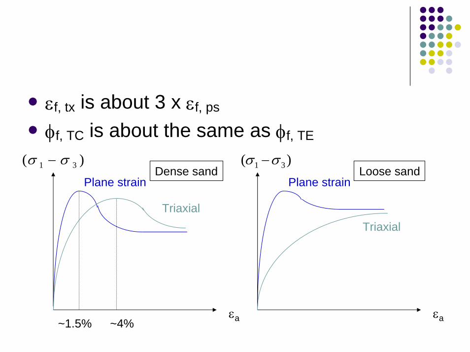
εf, tx is about 3 x εf, ps
φf, TC is about the same as φf, TE
)( 31 σσ −
εa
Triaxial
Plane strain
~1.5% ~4%
Dense sand)( 31 σσ −
Plane strain
Triaxial
Loose sand
εa