Selection, installation and assembly of surge protective ...
50
Selection, installation and assembly of surge protective devices (SPDs) 8
Transcript of Selection, installation and assembly of surge protective ...
Selection, installation and assembly of surge
protective devices (SPDs)
8
LIGHTNING PROTECTION GUIDE 217www.dehn-international.com
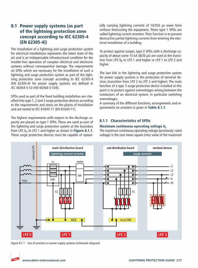
Figure 8.1.1 Use of arresters in power supply systems (schematic diagram)
edly carrying lightning currents of 10/350 μs wave form without destructing the equipment. These type 1 SPDs are called lightning current arresters. Their function is to prevent destructive partial lightning currents from entering the elec-trical installation of a building.
To protect against surges, type 2 SPDs with a discharge ca-pacity of about some 10 kA (8/20 μs) are used at the transi-tion from LPZ 0B to LPZ 1 and higher or LPZ 1 to LPZ 2 and higher.
The last link in the lightning and surge protection system for power supply systems is the protection of terminal de-vices (transition from LPZ 2 to LPZ 3 and higher). The main function of a type 3 surge protective device installed at this point is to protect against overvoltages arising between the conductors of an electrical system, in particular switching overvoltages. A summary of the different functions, arrangements and re-quirements on arresters is given in Table 8.1.1.
8.1.1 Characteristics of SPDsMaximum continuous operating voltage UcThe maximum continuous operating voltage (previously: rated voltage) is the root mean square (rms) value of the maximum
8.1 Power supply systems (as part of the lightning protection zone concept according to IEC 62305-4 (EN 62305-4))
The installation of a lightning and surge protection system for electrical installations represents the latest state of the art and is an indispensable infrastructural condition for the trouble-free operation of complex electrical and electronic systems without consequential damage. The requirements on SPDs which are necessary for the installation of such a lightning and surge protection system as part of the light-ning protection zone concept according to IEC 62305-4 (EN 62305-4) for power supply systems are defined in IEC 60364-5-53 (HD 60364-5-534).
SPDs used as part of the fixed building installation are clas-sified into type 1, 2 and 3 surge protective devices according to the requirements and stress on the places of installation and are tested to IEC 61643-11 (EN 61643-11).
The highest requirements with respect to the discharge ca-pacity are placed on type 1 SPDs. These are used as part of the lightning and surge protection system at the boundary from LPZ 0A to LPZ 1 and higher as shown in Figure 8.1.1. These surge protective devices must be capable of repeat-
terminal devices
L1L2L3N PE
sub-distribution board
F3
local EBB
main distribution board
F2
WhSEBPEN
meterF1
MEB
exte
rnal
LPS
surge arresterlightning current arrester
218 LIGHTNING PROTECTION GUIDE www.dehn-international.com
230/400 V three-phase system only applies to equipment of the fixed electrical installation. Equipment in the final cir-cuits supplied by this installation requires a voltage protec-tion level which is much lower than 2.5 kV.IEC 60364-5-53 (HD 60364-5-534) also requires a minimum voltage protection level of 1.5 kV for a 230/400 V low-voltage consumers‘ installation – for consumers according to overvoltage category I. This minimum voltage protection level can be achieved by means of a coordinated system of type 1 and type 2 SPDs or by using a type 1 combined arrester.
Short-circuit withstand capability ISCCRThis is the value of the prospective power-frequency short-circuit current which the surge protective device can safely handle in case it is provided with an upstream backup fuse (backup protection).
Follow current extinguishing capability Ifi (at Uc)The follow current extinguishing capability is the unaffected (prospective) rms value of the mains follow current which can be automatically extinguished by the surge protective device when Uc is applied.According to IEC 62305-3 (EN 62305-3) and IEC 60364-5-53 (HD 60364-5-534), the follow current extinguishing capabil-ity of the SPDs should be equal to the maximum prospective short-circuit current at the place of installation of the SPDs. In case of distribution boards in industrial plants with too high short-circuit currents, an adequate backup fuse which interrupts the mains follow current by means of the protec-tive device must be chosen for the protective device.According to IEC 60364-5-53 (HD 60364-5-534) and IEC 61643-11 (EN 61643-11), the SPDs which are connected between the neutral and PE conductor and where a power-frequency follow current may occur after they have oper-ated (e.g. spark gaps) have a follow current extinguishing capability Ifi ≥ 100 Arms .
Follow current limitation (in case of spark-gap-based type 1 SPDs)Follow current limitation is the capability of a spark-gap-based SPD to limit any mains follow currents which arise to
voltage which may be applied to the correspondingly labelled terminals of the surge protective device during operation. It is the maximum voltage applied to the arrester in the defined non-conductive state which ensures that this state is restored after the operation and discharge process.The value Uc depends on the nominal voltage of the sys-tem to be protected and the requirements of the installation standard (IEC 60364-5-53 (HD 60364-5-534)). Taking into account a 10 % voltage tolerance for TN and TT systems, the maximum continuous operating voltage Uc for 230/400 V systems is 253 V.
Lightning impulse current IimpThis is a standardised impulse current curve with a 10/350 μs wave form. Its parameters (peak value, charge, specific ener-gy) simulate the stress caused by natural lightning currents.Lightning impulse currents (10/350 μs) apply to type 1 SPDs. They must be able to discharge such lightning impulse cur-rents several times without destructing the equipment.
Nominal discharge current InThe nominal discharge current In is the peak value of the current flowing through the surge protective device (SPD). It has an 8/20 μs impulse current wave form and is rated for classifying the test of type 2 SPDs.
Voltage protection level UpThe voltage protection level of an SPD denotes the maxi-mum instantaneous value of the voltage on the terminals of an SPD while at the same time characterising their capacity to limit surges to a residual level.
Depending on the type of SPD, the voltage protection level is determined by means of the following individual tests:
¨ Impulse sparkover voltage 1.2/50 μs (100 %)
¨ Residual voltage Ures at nominal discharge current (in ac-cordance with IEC 61643-11 (EN 61643-11))
The surge protective device appropriate to the place of in-stallation is chosen in accordance with the overvoltage cat-egories described in IEC 60664-1 (EN 60664-1). It must be observed that the required minimum value of 2.5 kV for a
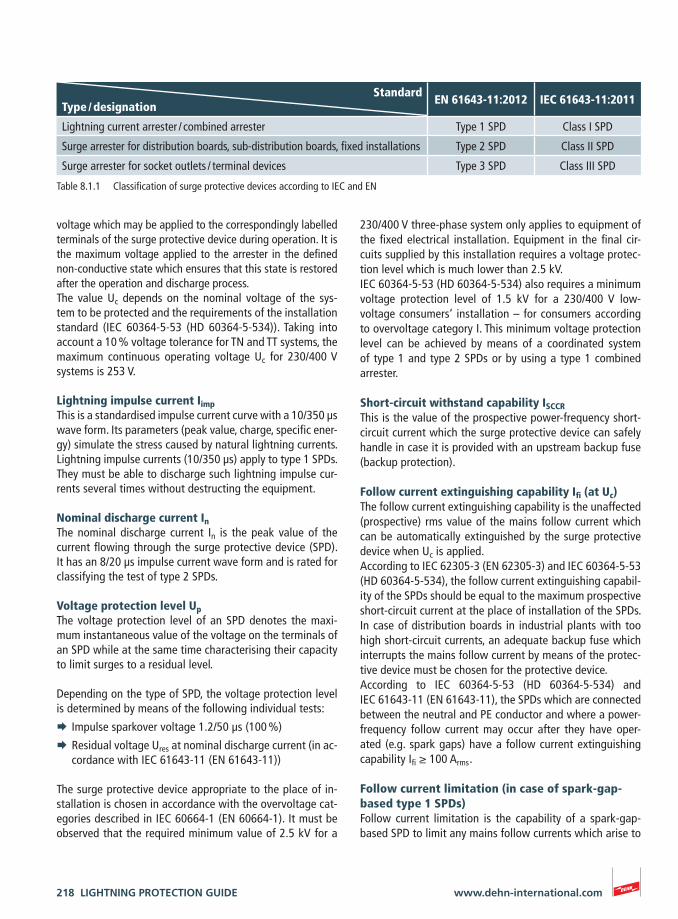
Table 8.1.1 Classification of surge protective devices according to IEC and EN
StandardType / designation
EN 61643-11:2012 IEC 61643-11:2011
Lightning current arrester / combined arrester Type 1 SPD Class I SPD
Surge arrester for distribution boards, sub-distribution boards, fixed installations Type 2 SPD Class II SPD
Surge arrester for socket outlets / terminal devices Type 3 SPD Class III SPD
LIGHTNING PROTECTION GUIDE 219www.dehn-international.com
tion for the SPDs between L and N for 5 s. The SPD needs to withstand this TOV.In addition to this also a TOV test with √3 x UREF = √3 x 255 V = 441,7 V for 120 min must be applied between L and N to simulate a loss of neutral. A safe failure mode is acceptable for this test.If TOVs arise as a result of earth faults in the high-voltage system, a rated time of 200 ms produces UTOV = 1200 V for the N-PE path in TT systems.IEC 60364-5-53 (HD 60364-5-534) requires that SPDs in-stalled in low-voltage consumer’s installations have a TOV withstand capability. The devices of the Red/Line family must be rated for TOVs according to IEC 61643-11 (EN 61643-11) and meet the requirements of IEC 60364-5-53 (HD 60364-5-534).
8.1.2 Use of SPDs in various systemsPersonal protection measures always take priority over surge protection measures. Since both measures are directly linked to the type of system and thus to the use of surge protective devices (SPDs), TN, TT and IT systems and the many ways in which SPDs can be used in these systems will be described in the following. Electric currents flowing through the hu-man body can have serious consequences. Therefore, protec-tion measures which prevent hazardous electric shock are required in every electrical installation. Parts which are en-ergised during normal operation must be insulated, covered, sheathed or arranged to prevent that they are touched if this could result in hazardous electric shock. This protection measure is termed “protection against electric shock under normal conditions”. Moreover, a hazard caused by electric shock must be prevented if the voltage is transferred to the metal enclosure (body of a piece of electrical equipment) due to a fault, e.g. a faulty insulation. This protection against hazards which, in the event of a fault, may result from touching bodies or extraneous conductive parts is termed “protection against electric shock under fault conditions”.
The limit for the permanently permissible touch voltage UL
typically is 50 V for a.c. voltages and 120 V for d.c. volt-ages.In circuits containing socket outlets and in circuits contain-ing class I mobile equipment, which is continuously handheld during operation, higher touch voltages, which can arise in the event of a fault, must be automatically disconnected within 0.4 s. In all other circuits, higher touch voltages must be automatically disconnected within 5 s. These times apply to TN systems. In case of other system configurations, the dis-connection times may differ.
such a degree that the current actually flowing is noticeably smaller than the possible short-circuit current at the place of installation.A high degree of follow current limitation prevents up-stream protection elements (e.g. fuses) from tripping due to a too high mains follow current. The follow current limitation is an important parameter for the availability of the electrical installation, particularly for spark-gap-based SPDs with a low voltage protection level. This is also described in the German VDN guideline 2004-08: “Überspannungs-Schutzeinrichtungen Typ 1. Richtlinie für den Einsatz von Überspannungs-Schutzeinrichtungen (ÜSE) Typ 1 (bisher Anforderungsklasse B) in Hauptstrom-versorgungssystemen.“ [Surge Protective Devices Type 1 – Guideline for the use of surge protective devices (SPDs) Type 1 in main power supply systems].Modern follow current limiting spark gaps even ensure se-lectivity with respect to low-rated fuses in the range from 20 to 35 AgK/gG.
CoordinationIn order to ensure that the various SPDs function selec-tively, energy coordination of the individual SPDs is abso-lutely essential. The basic principle of energy coordination is characterised by the fact that each protection stage must only discharge the amount of interference energy which the SPD is designed for. If higher interference ener-gies occur, the protection stage upstream of the SPD, e.g. type 1 SPD, must discharge the impulse current and re-lieve the downstream protective devices. Such coordina-tion must take into account all possible interference such as switching overvoltages, partial lightning currents, etc. Coordination must be proven by the manufacturer ac-cording to IEC 62305-4 (EN 62305-4), IEC 60364-5-53 (HD 60364-5-534) and the German VDN guideline.When using devices from different manufacturers, proper coordination cannot be assumed without making specific calculations or performing a laboratory test as outlined in the German bulletin 19 published by the ABB (Committee for Lightning Protection and Lightning Research of the VDE).The devices of the Red/Line family are harmonised and test-ed with reference to their energy coordination.
TOVTOV (Temporary OverVoltage) is the term used to describe temporary power-frequency surges which can arise as a re-sult of faults in medium and low-voltage systems. In case of TN systems as well as the L-N path in TT systems, a rated time of 5 seconds produces UTOV = 1.45 x U0 , where U0 rep-resents the nominal a.c. voltage of the phase conductors to earth. In case of 230/400 V systems, a TOV UTOV = 1.32 x UREF =1.32 x 255 V = 336.6 V must be taken into considera-
220 LIGHTNING PROTECTION GUIDE www.dehn-international.com
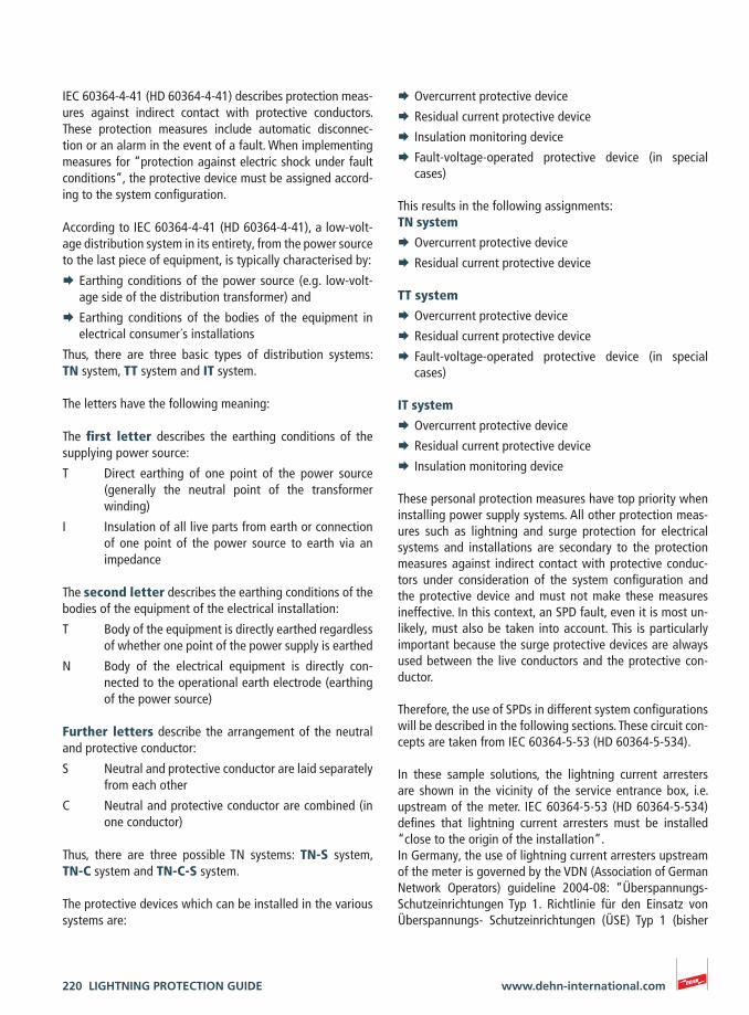
¨ Overcurrent protective device
¨ Residual current protective device
¨ Insulation monitoring device
¨ Fault-voltage-operated protective device (in special cases)
This results in the following assignments:TN system
¨ Overcurrent protective device
¨ Residual current protective device
TT system
¨ Overcurrent protective device
¨ Residual current protective device
¨ Fault-voltage-operated protective device (in special cases)
IT system
¨ Overcurrent protective device
¨ Residual current protective device
¨ Insulation monitoring device
These personal protection measures have top priority when installing power supply systems. All other protection meas-ures such as lightning and surge protection for electrical systems and installations are secondary to the protection measures against indirect contact with protective conduc-tors under consideration of the system configuration and the protective device and must not make these measures ineffective. In this context, an SPD fault, even it is most un-likely, must also be taken into account. This is particularly important because the surge protective devices are always used between the live conductors and the protective con-ductor.
Therefore, the use of SPDs in different system configurations will be described in the following sections. These circuit con-cepts are taken from IEC 60364-5-53 (HD 60364-5-534).
In these sample solutions, the lightning current arresters are shown in the vicinity of the service entrance box, i.e. upstream of the meter. IEC 60364-5-53 (HD 60364-5-534) defines that lightning current arresters must be installed “close to the origin of the installation”.In Germany, the use of lightning current arresters upstream of the meter is governed by the VDN (Association of German Network Operators) guideline 2004-08: “Überspannungs-Schutzeinrichtungen Typ 1. Richtlinie für den Einsatz von Überspannungs- Schutzeinrichtungen (ÜSE) Typ 1 (bisher
IEC 60364-4-41 (HD 60364-4-41) describes protection meas-ures against indirect contact with protective conductors. These protection measures include automatic disconnec-tion or an alarm in the event of a fault. When implementing measures for “protection against electric shock under fault conditions”, the protective device must be assigned accord-ing to the system configuration.
According to IEC 60364-4-41 (HD 60364-4-41), a low-volt-age distribution system in its entirety, from the power source to the last piece of equipment, is typically characterised by:
¨ Earthing conditions of the power source (e.g. low-volt-age side of the distribution transformer) and
¨ Earthing conditions of the bodies of the equipment in electrical consumer´s installations
Thus, there are three basic types of distribution systems: TN system, TT system and IT system.
The letters have the following meaning:
The first letter describes the earthing conditions of the supplying power source:
T Direct earthing of one point of the power source (generally the neutral point of the transformer winding)
I Insulation of all live parts from earth or connection of one point of the power source to earth via an impedance
The second letter describes the earthing conditions of the bodies of the equipment of the electrical installation:
T Body of the equipment is directly earthed regardless of whether one point of the power supply is earthed
N Body of the electrical equipment is directly con-nected to the operational earth electrode (earthing of the power source)
Further letters describe the arrangement of the neutral and protective conductor:
S Neutral and protective conductor are laid separately from each other
C Neutral and protective conductor are combined (in one conductor)
Thus, there are three possible TN systems: TN-S system, TN-C system and TN-C-S system.
The protective devices which can be installed in the various systems are:
LIGHTNING PROTECTION GUIDE 221www.dehn-international.com
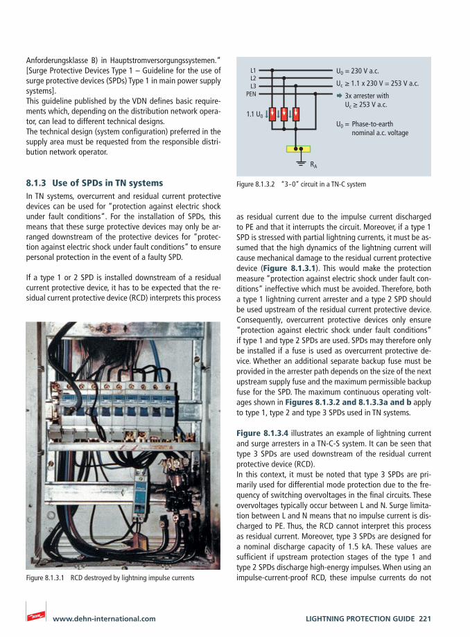
as residual current due to the impulse current discharged to PE and that it interrupts the circuit. Moreover, if a type 1 SPD is stressed with partial lightning currents, it must be as-sumed that the high dynamics of the lightning current will cause mechanical damage to the residual current protective device (Figure 8.1.3.1). This would make the protection measure “protection against electric shock under fault con-ditions” ineffective which must be avoided. Therefore, both a type 1 lightning current arrester and a type 2 SPD should be used upstream of the residual current protective device. Consequently, overcurrent protective devices only ensure “protection against electric shock under fault conditions” if type 1 and type 2 SPDs are used. SPDs may therefore only be installed if a fuse is used as overcurrent protective de-vice. Whether an additional separate backup fuse must be provided in the arrester path depends on the size of the next upstream supply fuse and the maximum permissible backup fuse for the SPD. The maximum continuous operating volt-ages shown in Figures 8.1.3.2 and 8.1.3.3a and b apply to type 1, type 2 and type 3 SPDs used in TN systems.
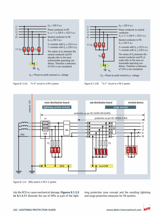
Figure 8.1.3.4 illustrates an example of lightning current and surge arresters in a TN-C-S system. It can be seen that type 3 SPDs are used downstream of the residual current protective device (RCD). In this context, it must be noted that type 3 SPDs are pri-marily used for differential mode protection due to the fre-quency of switching overvoltages in the final circuits. These overvoltages typically occur between L and N. Surge limita-tion between L and N means that no impulse current is dis-charged to PE. Thus, the RCD cannot interpret this process as residual current. Moreover, type 3 SPDs are designed for a nominal discharge capacity of 1.5 kA. These values are sufficient if upstream protection stages of the type 1 and type 2 SPDs discharge high-energy impulses. When using an impulse-current-proof RCD, these impulse currents do not
Anforderungsklasse B) in Hauptstromversorgungssystemen.“ [Surge Protective Devices Type 1 – Guideline for the use of surge protective devices (SPDs) Type 1 in main power supply systems].This guideline published by the VDN defines basic require-ments which, depending on the distribution network opera-tor, can lead to different technical designs.The technical design (system configuration) preferred in the supply area must be requested from the responsible distri-bution network operator.
8.1.3 Use of SPDs in TN systemsIn TN systems, overcurrent and residual current protective devices can be used for “protection against electric shock under fault conditions“. For the installation of SPDs, this means that these surge protective devices may only be ar-ranged downstream of the protective devices for “protec-tion against electric shock under fault conditions” to ensure personal protection in the event of a faulty SPD.
If a type 1 or 2 SPD is installed downstream of a residual current protective device, it has to be expected that the re-sidual current protective device (RCD) interprets this process
Figure 8.1.3.1 RCD destroyed by lightning impulse currents
L1L2L3
PEN
RA
1.1 U0
U0 = 230 V a.c.
Uc ≥ 1.1 x 230 V = 253 V a.c.
3x arrester with Uc ≥ 253 V a.c.
U0 = Phase-to-earth nominal a.c. voltage
Figure 8.1.3.2 “3 – 0” circuit in a TN-C system
222 LIGHTNING PROTECTION GUIDE www.dehn-international.com
ning protection zone concept and the resulting lightning and surge protection measures for TN systems.
trip the RCD or cause mechanical damage. Figures 8.1.3.5 to 8.1.3.11 illustrate the use of SPDs as part of the light-
L1L2L3N PE
F3F2
Wh
F1
PEN
RCD
terminal devicessub-distribution board
local EBB
main distribution board
SEB
exte
rnal
LPS
MEB
protection as per IEC 60364-4-443
protection as per IEC 62305 (EN 62305)
surge arresterlightning current arrester
Figure 8.1.3.4 SPDs used in a TN-C-S system
U0
L1L2L3N
PE
RA
U0 = 230 V a.c.
Phase conductor to PE:Uc ≥ 1.1 x 230 V = 253 V a.c.
Neutral conductor to PE:Uc ≥ 230 V a.c.
3 x arrester with Uc ≥ 253 V a.c.1 x arrester with Uc ≥ 230 V a.c.
The values of U0 between the neutral conductor and PE already refer to the most unfavourable operating con-ditions. Therefore a tolerance of 10 % is not considered.
U0 = Phase-to-earth nominal a.c. voltage
1.1 U0
Figure 8.1.3.3a “4 – 0” circuit in a TN-S system
U0
L1L2L3N
PE
RA
U0 = 230 V a.c.
Phase conductor to neutral conductor:Uc ≥ 1.1 x 230 V = 253 V a.c.
Neutral conductor to PE:Uc ≥ 230 V a.c.
3 x arrester with Uc ≥ 253 V a.c.1 x arrester with Uc ≥ 230 V a.c.
The values of U0 between the neutral conductor and PE al- ready refer to the most un- favourable operating con- ditions. Therefore a tolerance of 10 % is not considered.
1.1 U0
U0 = Phase-to-earth nominal a.c. voltage
Figure 8.1.3.3b “3+1” circuit in a TN-S system
LIGHTNING PROTECTION GUIDE 223www.dehn-international.com
surge arresterlightning current arrester
RCD
L1L2L3N PE
F3
Wh
F2
F1
terminal devicessub-distribution board
local EBB
main distribution boardex
tern
al L
PS
MEB
protection as per IEC 60364-4-443
protection as per IEC 62305 (EN 62305)
SEB
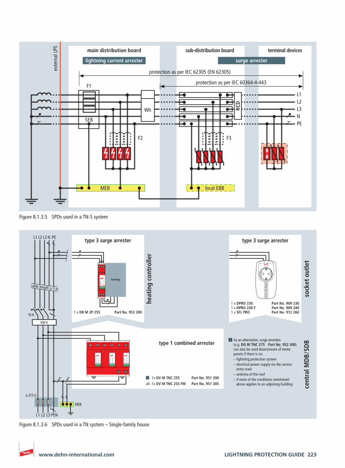
Figure 8.1.3.5 SPDs used in a TN-S system
PR
OT
EC
TO
R
DEH
Nra
il
DR M
2P
255
FM
21
L1 L2 L3 N PE
16 A
sock
et o
utle
t
MEB
heat
ing
cont
rolle
r
1x DV M TNC 255 Part No. 951 300
alt. 1x DV M TNC 255 FM Part No. 951 305
As an alternative, surge arresters(e.g. DG M TNC 275 Part No. 952 300)can also be used downstream of meter panels if there is no– lightning protection system– electrical power supply via the service entry mast– antenna of the roof– if none of the conditions mentioned above applies to an adjoining building ce
ntra
l MD
B / S
DB
1 x DPRO 230 Part No. 909 2301 x DPRO 230 F Part No. 909 2401 x SFL PRO Part No. 912 2601 x DR M 2P 255 Part No. 953 200
KW h
heating
L1 L2 L3 PEN
type 1 combined arrester
type 3 surge arrester type 3 surge arrester
cable length ≥ 5 m
DV
MO
D 2
55
DEH
Nve
nti
l
DV
MO
D 2
55
DEH
Nve
nti
l
DV
MO
D 2
55
DEH
Nve
nti
l
L1 L2 L3L1' L2' L3'
PEN
≤ 315 A
Figure 8.1.3.6 SPDs used in a TN system – Single-family house
224 LIGHTNING PROTECTION GUIDE www.dehn-international.com
DEH
Ngu
ard
DG M
OD
275
DEH
Ngu
ard
DG M
OD
275
L1 L2
PED
EHN
guar
d
DG M
OD
275
L3
DEH
Ngu
ard
DG M
OD
275
N
DEH
Ngu
ard
DG M
OD
275
DEH
Ngu
ard
DG M
OD
275
L1 L2
PE
DEH
Ngu
ard
DG M
OD
275
L3
DEH
Ngu
ard
DG M
OD
275
N
L1 L1’ L2 L2’ L3 L3’
N‘/PEN N/PEN
DEHNbloc DB 3 255 H
L1 L1‘ L2 L2‘
PEN
L3 L3‘
DEH
Nve
ntil
DV M
OD
255
DEH
Nve
ntil
DV M
OD
255
DEH
Nve
ntil
DV M
OD
255
DEH
Nbl
oc
DB M
1 2
55 F
M
N/PE(N)
L/N
DEH
Nbl
oc
DB M
1 2
55 F
M
N/PE(N)
L/N
DEH
Nbl
oc
DB M
1 2
55 F
M
N/PE(N)
L/N
S-Schutz
DEHNflex
L1 L2 L3 N PE
L1 L2 L3 PEN
16 A
sock
et o
utle
t
1 x DSA 230 LA Part No. 924 370for cable ducts
1 x STC 230 Part No. 924 350for existing socket outlets
with remote signalling contact:1 x DG M TNS 275 FM Part No. 952 405
1 x DV M TNC 255 Part No. 951 300alt. 1 x DV M TNC 255 FM Part No. 951 305also available as
1 x DV M TNS 255 Part No. 951 400alt. 1 x DV M TNS 255 FM Part No. 951 405
125 A 125 A
1 x DG M TNS 275 Part No. 952 400
cable length ≥ 15 m
1 x DB 3 255 H Part No. 900 120
alt. 3 x DB 1 255 H Part No. 900 2221 x MVS 1 6 Part No. 900 815
315 A
3 x DB M 1 255 FM Part No. 961 1251 x MVS 1 6 Part No. 900 815
alt. 3 x DB M 1 255 Part No. 961 1201 x MVS 1 6 Part No. 900 815
sub-
dist
ribu
tion
boa
rd315 A
1 x DFL M 255 Part No. 924 396for flush-mounted systems
315 A
cable length ≥ 5 m
type 3 surge arrester type 3 surge arrester type 3 surge arrester
type 2 surge arrester type 2 surge arrester
faul
t ind
icat
ion
faul
t ind
icat
ion
MEB
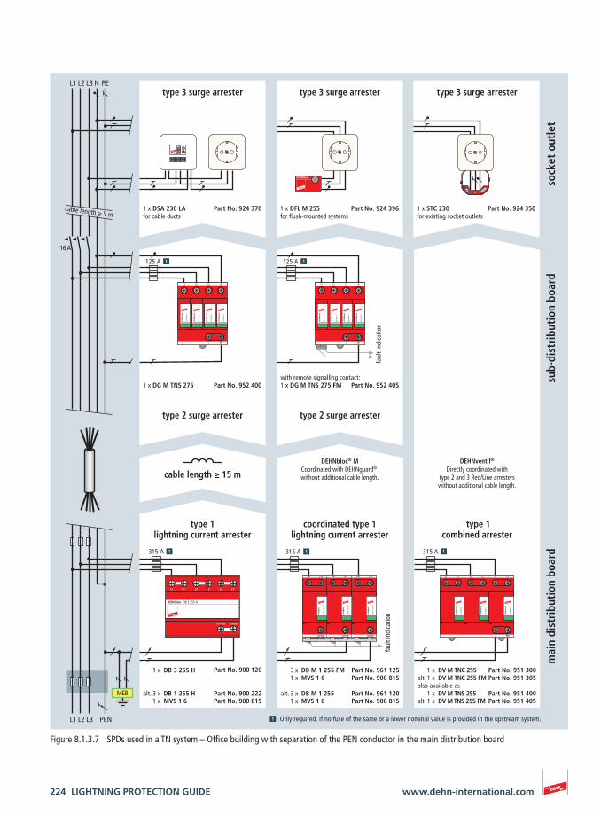
Only required, if no fuse of the same or a lower nominal value is provided in the upstream system.
type 1combined arrester
DEHNventil®
Directly coordinated withtype 2 and 3 Red/Line arresterswithout additional cable length.
coordinated type 1lightning current arrester
DEHNbloc® MCoordinated with DEHNguard® without additional cable length.
type 1lightning current arrester
mai
n di
stri
buti
on b
oard
Figure 8.1.3.7 SPDs used in a TN system – Office building with separation of the PEN conductor in the main distribution board
LIGHTNING PROTECTION GUIDE 225www.dehn-international.com
PR
OT
EC
TO
R
Überspannungsschutz
DEH
Ngu
ard
DG M
OD
275
DEH
Ngu
ard
DG M
OD
275
L1 L2
PEN
DEH
Ngu
ard
DG M
OD
275
L3
DEH
Ngu
ard
DG M
OD
275
DEH
Ngu
ard
DG M
OD
275
L1 L2
PEN
DEH
Ngu
ard
DG M
OD
275
L3
L1 L1‘ L2 L2‘
PEN
L3 L3‘
DEH
Nve
ntil
DV M
OD
255
DEH
Nve
ntil
DV M
OD
255
DEH
Nve
ntil
DV M
OD
255
DEH
Nbl
oc
DB M
1 2
55 F
M
N/PE(N)
L/N
DEH
Nbl
oc
DB M
1 2
55 F
M
N/PE(N)
L/N
DEH
Nbl
oc
DB M
1 2
55 F
M
N/PE(N)
L/N
DB H
MO
D 25
5
DEH
Nbl
oc
L/N L’/N’
N/PE(N)
DB H
MO
D 25
5
DEH
Nbl
oc
L/N L’/N’
N/PE(N)
DB H
MO
D 25
5
DEH
Nbl
oc
L/N L’/N’
N/PE(N)
0
1
ÜBERSPAN
NU
NG
SSCHUTZ
DEFECT FUN
CTION
SURG
E PROTECTOR
FREQU
ENZFILTER
FREQU
ENCY FILTER
NETZFILTER
LINE FILTER
L1 L2 L3 PEN
L1 L2 L3 N PE
16 A
sock
et o
utle
tm
ain
dist
ribu
tion
boa
rdsu
b-di
stri
buti
on b
oard
1 x NSM PRO EW Part No. 924 342 1 x DPRO 230 F Part No. 909 2401 x DPRO 230 Part No. 909 230
1 x DG M TNC 275 Part No. 952 300with remote signalling contact:1 x DG M TNC 275 FM Part No. 952 305
1 x DV M TNC 255 Part No. 951 300
alt. 1 x DV M TNC 255 FM Part No. 951 305
125 A 125 A
315 A 315 A
3 x DB M 1 255 FM Part No. 961 1251 x MVS 1 6 Part No. 900 815
alt. 3 x DB M 1 255 Part No. 961 1201 x MVS 1 6 Part No. 900 815
315 A
type 3 surge arrester type 3 surge arrester type 3 surge arrester
cable length ≥ 5 m
cable length ≥ 15 m
type 2 surge arrester type 2 surge arrester
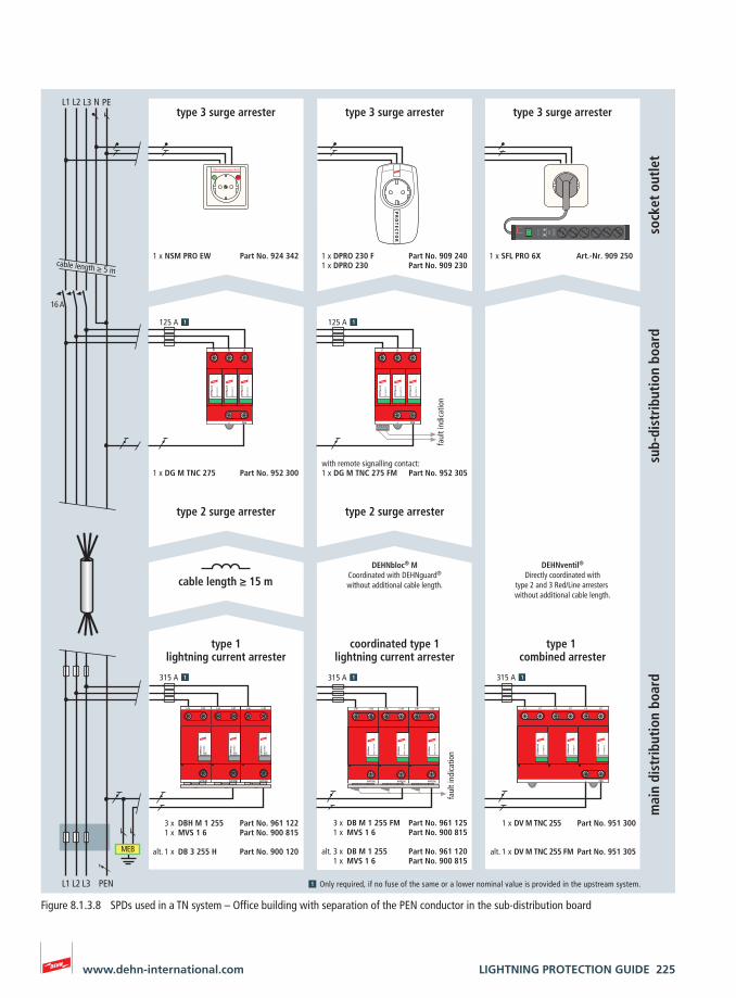
type 1 combined arrester
DEHNventil®
Directly coordinated withtype 2 and 3 Red/Line arresters without additional cable length.
coordinated type 1lightning current arrester
DEHNbloc® MCoordinated with DEHNguard®
without additional cable length.
type 1lightning current arrester
faul
t ind
icat
ion
faul
t ind
icat
ion
MEB
Only required, if no fuse of the same or a lower nominal value is provided in the upstream system.
1 x DB 3 255 H Part No. 900 120alt.
3 x DBH M 1 255 Part No. 961 1221 x MVS 1 6 Part No. 900 815
1 x SFL PRO 6X Art.-Nr. 909 250
Figure 8.1.3.8 SPDs used in a TN system – Office building with separation of the PEN conductor in the sub-distribution board
226 LIGHTNING PROTECTION GUIDE www.dehn-international.com
DEH
Ngu
ard
DG M
OD
275
DEH
Ngu
ard
DG M
OD
275
L1 L2
PEN
DEH
Ngu
ard
DG M
OD
275
L3
V NHV NH00 280
V NHV NH00 280
V NHV NH00 280
DEH
Nbl
oc
DB M
1 2
55 F
M
N/PE(N)
L/N
DEH
Nbl
oc
DB M
1 2
55 F
M
N/PE(N)
L/N
DEH
Nbl
oc
DB M
1 2
55 F
M
N/PE(N)
L/N
DEHN SPDSPS PRO
function
OUT / FM
/ IN
DEH
Nra
il
DR M
4P
255
FM
L1 L2 L3 N
L1 L2 L3 N
L1 L1‘ L2 L2‘
PEN
L3 L3‘
DEH
Nve
ntil
DV M
OD
255
DEH
Nve
ntil
DV M
OD
255
DEH
Nve
ntil
DV M
OD
255
DEH
Nrail
DR M 2P 255 FM
4 3
2 1
MAINS FILTER
L’ L’ N’ N’OUT
L L N NIN
DEHNbloc MaxiDBM NH00 255
DEHNbloc MaxiDBM NH00 255
DEHNbloc MaxiDBM NH00 255
L1 L2 L3 PEN
3 x V NH00 280 Part No. 900 261
3 x DBM NH00 255 Part No. 900 255
315 A
1 x DV M TNC 255 FM Part No. 951 305
alt. 1 x DV M TNC 255 Part No. 951 300
315 A
faul
t ind
icat
ion
1 x DG M TNC 275 Part No. 952 300or with remote signalling contact:1 x DG M TNC 275 FM Part No. 952 305
125 A
1 x SPS PRO Part No. 912 253 1 x DR M 4P 255 FM Part No. 953 405alt. 1 x DR M 4P 255 Part No. 953 400
1 x DR M 2P 255 FM Part No. 953 2051 x NF 10 Part No. 912 254
L1 L2 L3 N PE
cable length ≥ 5 m
32 A
swit
chge
ar c
abin
et / m
achi
ne
type 2 surge arrestertype 2 surge arrester
mai
n di
stri
buti
on b
oard
sub-
dist
ribu
tion
boa
rd
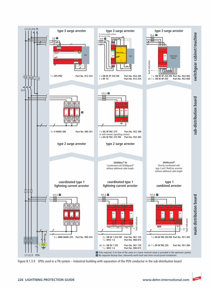
type 1combined arrester
type 3 surge arrester type 3 surge arrester type 3 surge arrester
DEHNventil®
Directly coordinated withtype 2 and 3 Red/Line arresterswithout additional cable length.
Only required, if no fuse of the same or a lower nominal value is provided in the upstream system.No separate backup fuse, inherently earth-fault and short-circuit-proof installation.
coordinated type 1lightning current arrester
DEHNbloc® MCoordinated with DEHNguard®
without additional cable length.
3 x DB M 1 255 FM Part No. 961 1251 x MVS 1 6 Part No. 900 815
alt. 3 x DB M 1 255 Part No. 961 1201 x MVS 1 6 Part No. 900 815
faul
t ind
icat
ion
faul
t ind
icat
ion
315 A
25 A also possible withoutNF 10 mains filter
coordinated type 1lightning current arrester
MEB
25 A3 A 10 A
electronicdevice
PLCPLC
Figure 8.1.3.9 SPDs used in a TN system – Industrial building with separation of the PEN conductor in the sub-distribution board
LIGHTNING PROTECTION GUIDE 227www.dehn-international.com
DEH
Ngu
ard
DG S
440
FM
DEH
Ngu
ard
DG S
440
FM
DEH
Ngu
ard
DG S
440
FM
N/PEN
L
DEH
Nbl
ocM
axi
DBM
1 4
40 F
M
N/PEN
L
DEH
Nbl
ocM
axi
DBM
1 4
40 F
M
N/PEN
L
DEH
Nbl
ocM
axi
DBM
1 4
40 F
M
L
DEH
Nbl
ocM
axi
DBM
1 7
60 F
M
L1 L2 L3 PEN
x DG S 440 FM Part No. 952 095x MVS 1 3 Part No. 900 615
125 A
MEB
250 A
L1 L2 L3 PEN
type 2 surge arrester
faul
t ind
icat
ion
coordinated type 1lightning current arrester
faul
t ind
icat
ion
3 x DBM 1 440 FM Part No. 961 145
alt. 3 x DBM 1 440 Part No. 961 1401 x EB DG 1000 1 3 Part No. 900 411
1 x EB DG 1000 1 3 Part No. 900 411
3 1
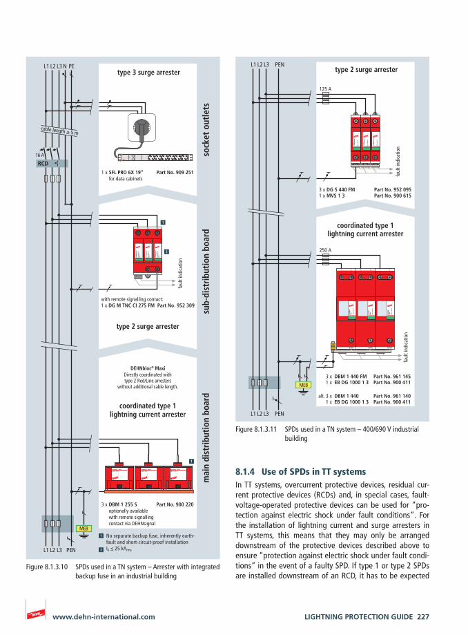
Figure 8.1.3.11 SPDs used in a TN system – 400/690 V industrial building
L1 L2
DG M
OD
Cl
275
DEH
Ngu
ard
DG M
OD
Cl
275
DEH
Ngu
ard
L3
DG M
OD
Cl
275
DEH
Ngu
ard
PEN
DEHNbloc® MaxiDBM 1 255 S
DEHNbloc® MaxiDBM 1 255 S
DEHNbloc® MaxiDBM 1 255 S
ÜBERSPANNUNGSSCHUTZ
SURGE PROTECTOR
DEFECT
FUNCTION
faul
t ind
icat
ion
cable length ≥ 5 m
MEB
L1 L2 L3 PEN
3 x DBM 1 255 Soptionally availablewith remote signallingcontact via DEHNsignal
Part No. 900 220
L1 L2 L3 N PE
16 A
sub-
dist
ribu
tion
boa
rdm
ain
dist
ribu
tion
boa
rd
RCD
DEHNbloc® MaxiDirectly coordinated withtype 2 Red/Line arresters
without additional cable length.
coordinated type 1lightning current arrester
type 2 surge arrester
No separate backup fuse, inherently earth-fault and short-circuit-proof installationIk ≤ 25 kArms
1 xwith remote signalling contact:
DG M TNC CI 275 FM
1 x SFL PRO 6X 19“for data cabinets
Part No. 909 251
type 3 surge arrester
sock
et o
utle
ts
Part No. 952 309
Figure 8.1.3.10 SPDs used in a TN system – Arrester with integrated backup fuse in an industrial building
8.1.4 Use of SPDs in TT systems In TT systems, overcurrent protective devices, residual cur-rent protective devices (RCDs) and, in special cases, fault-voltage-operated protective devices can be used for “pro-tection against electric shock under fault conditions“. For the installation of lightning current and surge arresters in TT systems, this means that they may only be arranged downstream of the protective devices described above to ensure “protection against electric shock under fault condi-tions” in the event of a faulty SPD. If type 1 or type 2 SPDs are installed downstream of an RCD, it has to be expected
228 LIGHTNING PROTECTION GUIDE www.dehn-international.com
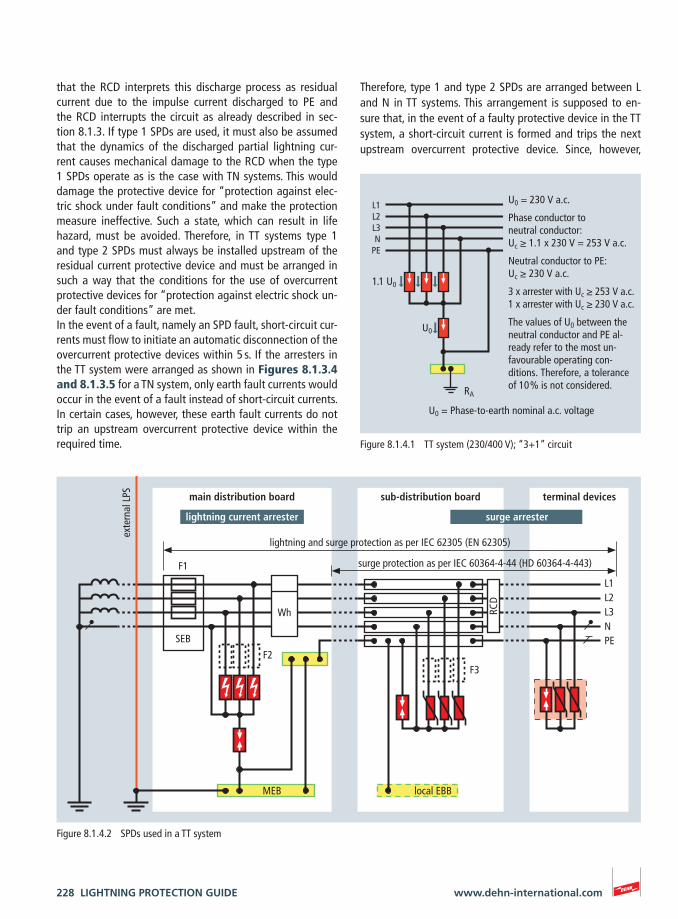
Therefore, type 1 and type 2 SPDs are arranged between L and N in TT systems. This arrangement is supposed to en-sure that, in the event of a faulty protective device in the TT system, a short-circuit current is formed and trips the next upstream overcurrent protective device. Since, however,
that the RCD interprets this discharge process as residual current due to the impulse current discharged to PE and the RCD interrupts the circuit as already described in sec-tion 8.1.3. If type 1 SPDs are used, it must also be assumed that the dynamics of the discharged partial lightning cur-rent causes mechanical damage to the RCD when the type 1 SPDs operate as is the case with TN systems. This would damage the protective device for “protection against elec-tric shock under fault conditions” and make the protection measure ineffective. Such a state, which can result in life hazard, must be avoided. Therefore, in TT systems type 1 and type 2 SPDs must always be installed upstream of the residual current protective device and must be arranged in such a way that the conditions for the use of overcurrent protective devices for “protection against electric shock un-der fault conditions” are met.In the event of a fault, namely an SPD fault, short-circuit cur-rents must flow to initiate an automatic disconnection of the overcurrent protective devices within 5 s. If the arresters in the TT system were arranged as shown in Figures 8.1.3.4 and 8.1.3.5 for a TN system, only earth fault currents would occur in the event of a fault instead of short-circuit currents. In certain cases, however, these earth fault currents do not trip an upstream overcurrent protective device within the required time.
U0
L1L2L3N
PE
RA
U0 = 230 V a.c.
Phase conductor to neutral conductor:Uc ≥ 1.1 x 230 V = 253 V a.c.
Neutral conductor to PE:Uc ≥ 230 V a.c.
3 x arrester with Uc ≥ 253 V a.c.1 x arrester with Uc ≥ 230 V a.c.
The values of U0 between the neutral conductor and PE al- ready refer to the most un-favourable operating con-ditions. Therefore, a tolerance of 10 % is not considered.
1.1 U0
U0 = Phase-to-earth nominal a.c. voltage
Figure 8.1.4.1 TT system (230/400 V); “3+1” circuit
L1L2L3N PE
F3F2
Wh
F1
RCD
terminal devicessub-distribution board
local EBB
main distribution board
SEB
exte
rnal
LPS
MEB
surge protection as per IEC 60364-4-44 (HD 60364-4-443)
lightning and surge protection as per IEC 62305 (EN 62305)
surge arresterlightning current arrester
Figure 8.1.4.2 SPDs used in a TT system
LIGHTNING PROTECTION GUIDE 229www.dehn-international.com
II Iimp ≥ 75 kA (10/350 μs)
III / IV Iimp ≥ 50 kA (10/350 μs)
The type 2 SPDs are also connected between L and N and be-tween N and PE. Type 2 SPDs between N and PE must have a discharge capacity of at least In ≥ 20 kA (8/20 μs) for three-phase systems and In ≥ 10 kA (8/20 μs) for a.c. systems.Since coordination is always based on the worst-case condi-tions (10/350 μs wave form), type 2 N-PE arresters of the Red/Line series have a value of 12 kA (10/350 μs).Figures 8.1.4.2 to 8.1.4.5 show examples of how to con-nect SPDs in TT systems. As is the case with TN systems, type 3 surge protective devices are installed downstream of the RCD. Generally, the impulse current discharged by this SPD is so low that the RCD does not identify this process as re-sidual current. Nevertheless, an impulse-current-proof RCD should also be used in this case.
8.1.5 Use of SPDs in IT systemsIn IT systems, overcurrent protective devices, residual cur-rent protective devices (RCDs) and insulation monitoring
lightning currents always flow to earth, namely PE, an ad-ditional discharge path must be provided between N and PE.These so-called “N-PE arresters” must meet special require-ments since in this case the sum of the partial discharge currents from L1, L2, L3 and N must be conducted and they must be capable of extinguishing follow currents of 100 Arms due to a possible shifting of the neutral point.Moreover, an N-PE arrester must fulfil increased TOV require-ments. According to IEC 60364-5-53 (HD 60364-5-534), a withstand capability of 1200 V for 200 ms must be proven.The maximum continuous operating voltages shown in Figure 8.1.4.1 must be observed when using SPDs in TT systems be-tween L and N.
The lightning current carrying capability of the type 1 SPDs is rated to conform to lightning protection levels I, II, III / IV as per IEC 62305-1 (EN 62305-1).The following values must be complied with to ensure the light-ning current carrying capability of SPDs between N and PE:
Lightning protection level:
I Iimp ≥ 100 kA (10/350 μs)
DEH
Nve
ntil
DV M
OD
255
DEH
Nve
ntil
DV M
OD
255
DEH
Nve
ntil
DV M
OD
255
DEH
Nve
ntil
DV M
OD
NPE
50
L1 L2
PE
L3 N
DEH
Nra
il
DR M
2P
255
FM
21
DEHNflex
RCD
L1 L2 L3 N PE
16 A
sock
et o
utle
ts
heat
ing
cont
rol
1 x DV M TT 255
cent
ral M
DB
/ SD
B1 x DR M 2P 255
MEB
125 A
1 x DFL M 255
heating
L1 L2 L3 N
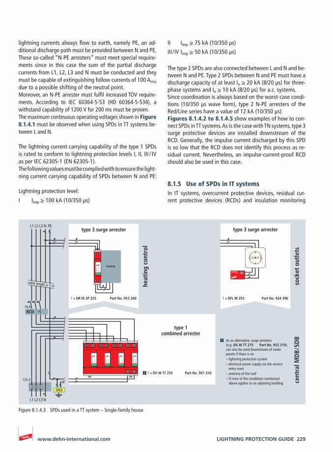
type 1combined arrester
As an alternative, surge arresters(e.g. DG M TT 275 Part No. 952 310),can also be used downstream of meter panels if there is no– lightning protection system– electrical power supply via the service entry mast– antenna of the roof– if none of the conditions mentioned above applies to an adjoining building
Part No. 951 310
Part No. 953 200 Part No. 924 396
type 3 surge arrester type 3 surge arrester
cable length ≥ 5 m
Figure 8.1.4.3 SPDs used in a TT system – Single-family house
230 LIGHTNING PROTECTION GUIDE www.dehn-international.com
DEH
Ngu
ard
DG M
OD
275
DEH
Ngu
ard
DG M
OD
275
L1 L2
PE
DEH
Ngu
ard
DG M
OD
275
L3 N
DEH
Ngu
ard
DG M
OD
NPE
DEH
Ngu
ard
DG M
OD
275
DEH
Ngu
ard
DG M
OD
275
L1 L2
PE
DEH
Ngu
ard
DG M
OD
275
L3 N
DEH
Ngu
ard
DG M
OD
NPE
DEHNflex
S-Schutz
DEH
Nve
ntil
DV M
OD
255
L1 L1‘ L2 L2‘
PE
L3 L3‘ N
DEH
Nve
ntil
DV M
OD
255
DEH
Nve
ntil
DV M
OD
255
DEH
Nve
ntil
DV M
OD
NPE
50
N
PE
DEH
Nga
p
DGP
M 2
55
DEH
Nbl
oc
DB M
1 2
55
N/PE(N)
L/N
DEH
Nbl
oc
DB M
1 2
55
N/PE(N)
L/N
DEH
Nbl
oc
DB M
1 2
55
N/PE(N)
L/N
DB H
MO
D 25
5
DEH
Nbl
oc
L/N L’/N’
N/PE(N)
DB H
MO
D 25
5
DEH
Nbl
oc
L/N L’/N’
N/PE(N)
DB H
MO
D 25
5
DEH
Nbl
oc
L/N L’/N’
N/PE(N)
DGPH
MO
D 25
5
DEH
Nga
p
PE
N
N‘
for cable ducts for existing socket outletsfor flush-mounted systems
cable length ≥ 5 m
type 3 surge arrester type 3 surge arrester type 3 surge arrester
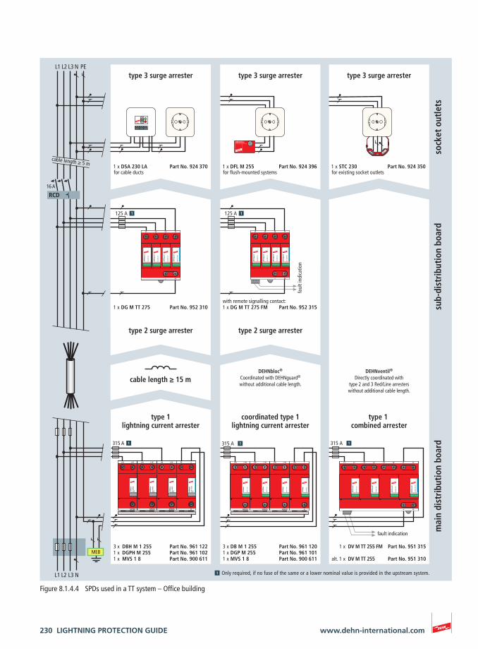
Only required, if no fuse of the same or a lower nominal value is provided in the upstream system.
MEB
L1 L2 L3 N
3 x DB M 1 255 Part No. 961 1201 x DGP M 255 Part No. 961 1011 x MVS 1 8 Part No. 900 611
1 x DV M TT 255 FM Part No. 951 315
alt. 1 x DV M TT 255 Part No. 951 310
315 A
L1 L2 L3 N PE
16 A
sock
et o
utle
ts
1 x DSA 230 LA Part No. 924 370 1 x STC 230 Part No. 924 350
with remote signalling contact:1 x DG M TT 275 FM Part No. 952 315
125 A 125 A
1 x DG M TT 275 Part No. 952 310
mai
n di
stri
buti
on b
oard
sub-
dist
ribu
tion
boa
rd
1 x DFL M 255 Part No. 924 396
RCD
315 A315 A
cable length ≥ 15 m
type 1lightning current arrester
DEHNbloc®
Coordinated with DEHNguard®
without additional cable length.
coordinated type 1lightning current arrester
DEHNventil®
Directly coordinated withtype 2 and 3 Red/Line arresterswithout additional cable length.
type 1 combined arrester
fault indication
type 2 surge arrester type 2 surge arrester
faul
t ind
icat
ion
3 x DBH M 1 255 Part No. 961 1221 x DGPH M 255 Part No. 961 1021 x MVS 1 8 Part No. 900 611
Figure 8.1.4.4 SPDs used in a TT system – Office building
LIGHTNING PROTECTION GUIDE 231www.dehn-international.com
DEH
Ngu
ard
DG M
OD
275
DEH
Ngu
ard
DG M
OD
275
L1 L2
PE
DEH
Ngu
ard
DG M
OD
275
L3 N
DEH
Ngu
ard
DG M
OD
NPE
DEH
Ngu
ard
DG M
OD
275
DEH
Ngu
ard
DG M
OD
275
L1 L2
PE
DEH
Ngu
ard
DG M
OD
275
L3 N
DEH
Ngu
ard
DG M
OD
NPE
DEH
Nve
ntil
DV M
OD
255
L1 L1‘ L2 L2‘
PE
L3 L3‘ N
DEH
Nve
ntil
DV M
OD
255
DEH
Nve
ntil
DV M
OD
255
DEH
Nve
ntil
DV M
OD
NPE
50
DEH
Nbl
oc
DB M
1 2
55 F
M
N/PE(N)
L/N
DEH
Nbl
oc
DB M
1 2
55 F
M
N/PE(N)
L/N
DEH
Nbl
oc
DB M
1 2
55 F
M
N/PE(N)
L/N
N
PE
DEH
Nga
p
DGP
M 2
55 F
M
DEH
Nrail
DR M 2P 255 FM
4 3
2 1
MAINS FILTER
L’ L’ N’ N’OUT
L L N NIN
DEHN SPDSPS PRO
function
OUT / FM
/ IN
DEH
Nra
il
DR M
4P
255
FM
L1 L2 L3 N
L1 L2 L3 N
N‘
DB H
MO
D 25
5
DEH
Nbl
oc
L/N L’/N’
N/PE(N)
DB H
MO
D 25
5
DEH
Nbl
oc
L/N L’/N’
N/PE(N)
DB H
MO
D 25
5
DEH
Nbl
oc
L/N L’/N’
N/PE(N)
DGPH
MO
D 25
5
DEH
Nga
p
PE
N
L1 L2 L3 N
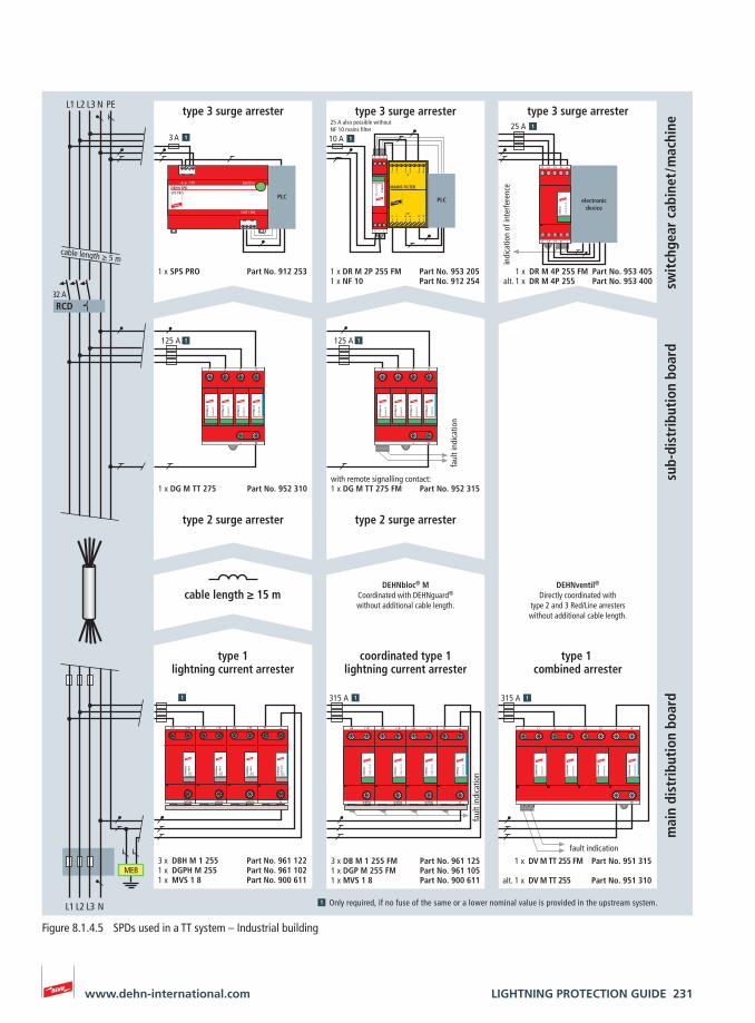
1 x DV M TT 255 FM Part No. 951 315
alt. 1 x DV M TT 255 Part No. 951 310
315 A
3 x DB M 1 255 FM Part No. 961 1251 x DGP M 255 FM Part No. 961 1051 x MVS 1 8 Part No. 900 611
315 A
L1 L2 L3 N PE
32 A
MEB
with remote signalling contact:1 x DG M TT 275 FM Part No. 952 315
125 A 125 A
1 x DG M TT 275 Part No. 952 310
mai
n di
stri
buti
on b
oard
sub-
dist
ribu
tion
boa
rd
1 x SPS PRO Part No. 912 253 1 x DR M 4P 255 FM Part No. 953 405alt. 1 x DR M 4P 255 Part No. 953 400
1 x DR M 2P 255 FM Part No. 953 2051 x NF 10 Part No. 912 254 sw
itch
gear
cab
inet
/ mac
hine
PLC PLC
RCD
cable length ≥ 5 m
type 2 surge arrestertype 2 surge arrester
type 3 surge arrester type 3 surge arrester type 3 surge arrester
DEHNventil®
Directly coordinated withtype 2 and 3 Red/Line arresterswithout additional cable length.
DEHNbloc® MCoordinated with DEHNguard®
without additional cable length.
indi
catio
n of
inte
rfere
nce
electronicdevice
faul
t ind
icat
ion
fault indication
Only required, if no fuse of the same or a lower nominal value is provided in the upstream system.
cable length ≥ 15 m
faul
t ind
icat
ion
25 A also possible without NF 10 mains filter
3 A25 A
10 A
type 1lightning current arrester
coordinated type 1lightning current arrester
type 1 combined arrester
3 x DBH M 1 255 Part No. 961 1221 x DGPH M 255 Part No. 961 1021 x MVS 1 8 Part No. 900 611
Figure 8.1.4.5 SPDs used in a TT system – Industrial building
232 LIGHTNING PROTECTION GUIDE www.dehn-international.com
choosing the SPDs with respect to their maximum continu-ous operating voltage.
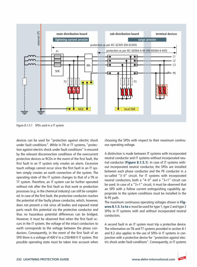
A distinction is made between IT systems with incorporated neutral conductor and IT systems without incorporated neu-tral conductor (Figure 8.1.5.1). In case of IT systems with-out incorporated neutral conductor, the SPDs are installed between each phase conductor and the PE conductor in a so-called “3 – 0” circuit. For IT systems with incorporated neutral conductors, both a “4 – 0” and a “3+1” circuit can be used. In case of a “3+1” circuit, it must be observed that an SPD with a follow current extinguishing capability ap-propriate to the system conditions must be installed in the N-PE path. The maximum continuous operating voltages shown in Fig-ures 8.1.5.1a to c must be used for type 1, type 2 and type 3 SPDs in IT systems with and without incorporated neutral conductors.
A second fault in an IT system must trip a protective device. The information on TN and TT systems provided in section 8.1 and 8.2 also applies to the use of SPDs in IT systems in con-junction with a protective device for "protection against elec-tric shock under fault conditions". Consequently, in IT systems
devices can be used for “protection against electric shock under fault conditions“. While in TN or TT systems, “protec-tion against electric shock under fault conditions” is ensured by the relevant disconnection conditions of the overcurrent protective devices or RCDs in the event of the first fault, the first fault in an IT system only creates an alarm. Excessive touch voltage cannot occur since the first fault in an IT sys-tem simply creates an earth connection of the system. The operating state of the IT system changes to that of a TN or TT system. Therefore, an IT system can be further operated without risk after the first fault so that work or production processes (e.g. in the chemical industry) can still be complet-ed. In case of the first fault, the protective conductor reaches the potential of the faulty phase conductor, which, however, does not present a risk since all bodies and exposed metal parts reach this potential via the protective conductor and thus no hazardous potential differences can be bridged. However, it must be observed that when the first fault oc-curs in the IT system, the voltage of the intact conductors to earth corresponds to the voltage between the phase con-ductors. Consequently, in the event of the first fault of an SPD there is a voltage of 400 V in a 230/400 V IT system. This possible operating state must be taken into account when
L1L2L3 PE
F3F2
Wh
F1
terminal devicessub-distribution board
local EBB
main distribution boardex
tern
al L
PS
MEB
protection as per IEC 60364-4-44 (HD 60364-4-443)
protection as per IEC 62305 (EN 62305)
SEB
surge arresterlightning current arrester
Figure 8.1.5.1 SPDs used in a IT system
LIGHTNING PROTECTION GUIDE 233www.dehn-international.com
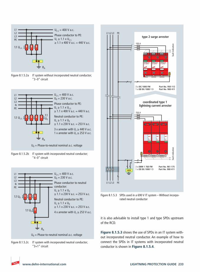
it is also advisable to install type 1 and type SPDs upstream of the RCD.
Figure 8.1.5.3 shows the use of SPDs in an IT system with-out incorporated neutral conductor. An example of how to connect the SPDs in IT systems with incorporated neutral conductor is shown in Figure 8.1.5.4.
L1L2L3PE
1.1 UL-L
RA
UL-L = 400 V a.c.
Phase conductor to PE:Uc ≥ 1.1 x UL-L≥ 1.1 x 400 V a.c. = 440 V a.c.
Figure 8.1.5.2a IT system without incorporated neutral conductor; “3 – 0” circuit
L1L2L3N
PE
RA
UL-L = 400 V a.c.U0 = 230 V a.c.
Phase conductor to PE:Uc ≥ 1.1 x UL-L≥ 1.1 x 400 V a.c. = 440 V a.c.
Neutral conductor to PE:Uc ≥ 1.1 x U0≥ 1.1 x 230 V a.c. = 253 V a.c.
3 x arrester with Uc ≥ 440 V a.c.1 x arrester with Uc ≥ 253 V a.c.
U0 = Phase-to-neutral nominal a.c. voltage
1.1U0
1.1 UL-L
Figure 8.1.5.2b IT system with incorporated neutral conductor; “4 – 0” circuit
L1L2L3N
PE
RA
UL-L = 400 V a.c.U0 = 230 V a.c.
Phase conductor to neutral conductor:Uc ≥ 1.1 x U0≥ 1.1 x 230 V a.c. = 253 V a.c.
Neutral conductor to PE:Uc ≥ 1.1 x U0≥ 1.1 x 230 V a.c. = 253 V a.c.
4 x arrester with Uc ≥ 253 V a.c.
1.1 U0
1.1 U0
U0 = Phase-to-neutral nominal a.c. voltage
Figure 8.1.5.2c IT system with incorporated neutral conductor; “3+1” circuit
N/PEN
L
DEH
Nbl
ocM
axi
DBM
1 7
60 F
M
N/PEN
L
DEH
Nbl
ocM
axi
DBM
1 7
60 F
M
N/PEN
L
DEH
Nbl
ocM
axi
DBM
1 7
60 F
M
DEHNguardDG 1000 FM
DEHNguardDG 1000 FM
DEHNguardDG 1000 FM
1
L1 L2 L3 PE
3 x DBM 1 760 FM Part No. 961 175x EB DG 1000 1 3 Part No. 900 411
3 x DG 1000 FM Part No. 950 1121 x EB DG 1000 1 3 Part No. 900 411
100 A
250 A
L1 L2 L3 PE
type 2 surge arrester
coordinated type 1 lightning current arrester
faul
t ind
icat
ion
faul
t ind
icat
ion
MEB
Figure 8.1.5.3 SPDs used in a 690 V IT system – Without incorpo-rated neutral conductor
234 LIGHTNING PROTECTION GUIDE www.dehn-international.com
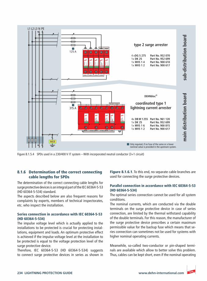
Figure 8.1.6.1. To this end, no separate cable branches are used for connecting the surge protective devices.
Parallel connection in accordance with IEC 60364-5-53 (HD 60364-5-534)The optimal series connection cannot be used for all system conditions. The nominal currents, which are conducted via the double terminals on the surge protective device in case of series connection, are limited by the thermal withstand capability of the double terminals. For this reason, the manufacturer of the surge protective device prescribes a certain maximum permissible value for the backup fuse which means that se-ries connection can sometimes not be used for systems with higher nominal operating currents.
Meanwhile, so-called two-conductor or pin-shaped termi-nals are available which allow to better solve this problem. Thus, cables can be kept short, even if the nominal operating
8.1.6 Determination of the correct connecting cable lengths for SPDs
The determination of the correct connecting cable lengths for surge protective devices is an integral part of the IEC 60364-5-53 (HD 60364-5-534) standard. The aspects described below are also frequent reasons for complaints by experts, members of technical inspectorates, etc. who inspect the installation.
Series connection in accordance with IEC 60364-5-53 (HD 60364-5-534)The impulse voltage level which is actually applied to the installations to be protected is crucial for protecting instal-lations, equipment and loads. An optimum protective effect is achieved if the impulse voltage level at the installation to be protected is equal to the voltage protection level of the surge protective device. Therefore, IEC 60364-5-53 (HD 60364-5-534) suggests to connect surge protective devices in series as shown in
DEH
Ngu
ard
DG M
OD
275
DEH
Ngu
ard
DG M
OD
275
DEH
Ngu
ard
DG M
OD
275
Feed
-Thr
ough
Term
inal
DK
25
DEH
Ngu
ard
DG M
OD
275
125 A
315 AD
B H
MO
D
255
DEH
Nbl
ocL/N L’/N’
N/PE(N)
DB
H M
OD
25
5
DEH
Nbl
oc
L/N L’/N’
N/PE(N)
DB
H M
OD
25
5
DEH
Nbl
oc
L/N L’/N’
N/PE(N)
DB
H M
OD
25
5
DEH
Nbl
oc
L/N L’/N’
N/PE(N)
Feed
-Thr
ough
Term
inal
DK
25
mai
n di
stri
buti
on b
oard
sub-
dist
ribu
tion
boa
rd
MEBOnly required, if no fuse of the same or a lower nominal value is provided in the upstream system.
type 2 surge arrester
coordinated type 1 lightning current arrester
DEHNbloc®
4 x DG S 275 Part No. 952 0701x DK 25 Part No. 952 6991x MVS 1 4 Part No. 900 6101x MVS 1 2 Part No. 900 617
4x DB M 1 255 Part No. 961 1201x DK 25 Part No. 952 6991x MVS 1 6 Part No. 900 8151x MVS 1 2 Part No. 900 617
L1 L2 L3 N PE
Figure 8.1.5.4 SPDs used in a 230/400 V IT system – With incorporated neutral conductor (3+1 circuit)
LIGHTNING PROTECTION GUIDE 235www.dehn-international.com
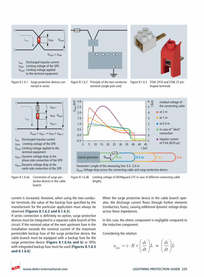
When the surge protective device in the cable branch oper-ates, the discharge current flows through further elements (conductors, fuses), causing additional dynamic voltage drops across these impedances.
In this case, the ohmic component is negligible compared to the inductive component.
Considering the relation
u i Rdidt
Ldidt
Ldyn
= ⋅ +
≈
current is increased. However, when using the two-conduc-tor terminals, the value of the backup fuse specified by the manufacturer for the particular application must always be observed (Figures 8.1.6.2 and 8.1.6.3). If series connection is definitely no option, surge protective devices must be integrated in a separate cable branch of the circuit. If the nominal value of the next upstream fuse in the installation exceeds the nominal current of the maximum permissible backup fuse of the surge protective device, the cable branch must be equipped with a backup fuse for the surge protective device (Figure 8.1.6.4a and b) or SPDs with integrated backup fuse must be used (Figures 8.1.6.5 and 8.1.6.6).
Utotal = uSPD
iimp Discharged impulse currentuSPD Limiting voltage of the SPDUtotal Limiting voltage applied
to the terminal equipment
UtotaluSPDiimp
Figure 8.1.6.1 Surge protective devices con-nected in series
Figure 8.1.6.2 Principle of the two-conductor terminal (single-pole unit)
Figure 8.1.6.3 STAK 2X16 and STAK 25 pin-shaped terminals
iimp Discharged impulse currentuSPD Limiting voltage of the SPDUtotal Limiting voltage applied to the
terminal equipmentudyn 1 Dynamic voltage drop at the
phase-side connection of the SPDudyn 2 Dynamic voltage drop at the
earth-side connection of the SPD
Utotal = udyn 1 + uSPD + udyn 2
UtotaluSPDiimp
udyn 1
udyn 2
Figure 8.1.6.4a Connection of surge pro-tective devices in the cable branch
Parameter: Length of the measuring line: 0.3 – 2.0 mUtotal: Voltage drop across the connecting cable and surge protective device
hybrid generator Utotal 0 m 0.3 m 1 m 2 m
3.0
2.5
2.0
1.5
1.0
0.5
0.0
-0.50 5 10 15 20 25 30 35 40 40 45
I [kA
]t [µs]
Uto
tal [
kV] 6
5
4
3
2
1
0
-1
residual voltage of the connecting cable:
at 2 m
at 1 m
at 0.3 m
in case of “ideal” connection
impulse current of 5 kA (8/20 µs)
Figure 8.1.6.4b Limiting voltage of DEHNguard 275 in case of different connecting cable lengths
236 LIGHTNING PROTECTION GUIDE www.dehn-international.com
c
L L
SPD
SPD
overcurrent protective device
overcurrent protective device
terminal device /installation
terminal device /installation
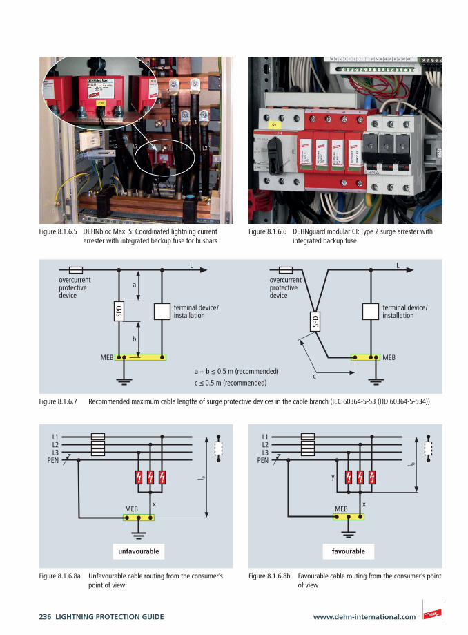
a + b ≤ 0.5 m (recommended)
c ≤ 0.5 m (recommended)
MEB MEB
a
b
Figure 8.1.6.7 Recommended maximum cable lengths of surge protective devices in the cable branch (IEC 60364-5-53 (HD 60364-5-534))
l a
L1L2L3
PEN
xMEB
unfavourable
Figure 8.1.6.8a Unfavourable cable routing from the consumer’s point of view
l b
L1L2L3
PEN
x
y
favourable
MEB
Figure 8.1.6.8b Favourable cable routing from the consumer’s point of view
Figure 8.1.6.5 DEHNbloc Maxi S: Coordinated lightning current arrester with integrated backup fuse for busbars
Figure 8.1.6.6 DEHNguard modular CI: Type 2 surge arrester with integrated backup fuse
LIGHTNING PROTECTION GUIDE 237www.dehn-international.com
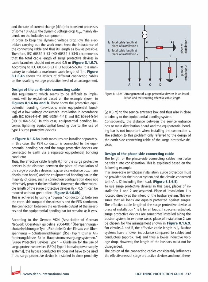
(≤ 0.5 m) to the service entrance box and thus also in close proximity to the equipotential bonding system. Consequently, the distance between the service entrance box or main distribution board and the equipotential bond-ing bar is not important when installing the connection y. The solution to this problem only referred to the design of the earth-side connecting cable of the surge protective de-vices.
Design of the phase-side connecting cableThe length of the phase-side connecting cables must also be taken into consideration. This is explained based on the following example:In a large-scale switchgear installation, surge protection must be provided for the busbar system and the circuits connected to it (A to D) including their loads (Figure 8.1.6.9). To use surge protective devices in this case, places of in-stallation 1 and 2 are assumed. Place of installation 1 is located directly at the infeed of the busbar system. This en-sures that all loads are equally protected against surges. The effective cable length of the surge protective device at place of installation 1 is l1 for all loads. If space is restricted, surge protective devices are sometimes installed along the busbar system. In extreme cases, place of installation 2 can be chosen for the arrangement shown in Figure 8.1.6.9. For circuits A and B, the effective cable length is l2. Busbar systems have a lower inductance compared to cables and conductors (approx. 1/4) and thus a lower inductive volt-age drop. However, the length of the busbars must not be disregarded. The design of the connecting cables considerably influences the effectiveness of surge protective devices and must there-
and the rate of current change (di/dt) for transient processes of some 10 kA/μs, the dynamic voltage drop Udyn mainly de-pends on the inductive component.In order to keep this dynamic voltage drop low, the elec-trician carrying out the work must keep the inductance of the connecting cable and thus its length as low as possible. Therefore, IEC 60364-5-53 (HD 60364-5-534) recommends that the total cable length of surge protective devices in cable branches should not exceed 0.5 m (Figure 8.1.6.7). According to IEC 60364-5-53 (HD 60364-5-534), it is man-datory to maintain a maximum cable length of 1 m. Figure 8.1.6.4b shows the effects of different connecting cables on the resulting voltage protection level of an arrangement.
Design of the earth-side connecting cable This requirement, which seems to be difficult to imple-ment, will be explained based on the example shown in Figures 8.1.6.8a and b. These show the protective equi-potential bonding (previously: main equipotential bond-ing) of a low-voltage consumer’s installation in accordance with IEC 60364-4-41 (HD 60364-4-41) and IEC 60364-5-54 (HD 60364-5-54). In this case, equipotential bonding be-comes lightning equipotential bonding due to the use of type 1 surge protective devices.
In Figure 8.1.6.8a, both measures are installed separately. In this case, the PEN conductor is connected to the equi-potential bonding bar and the surge protective devices are connected to earth via a separate equipotential bonding conductor. Thus, the effective cable length (la) for the surge protective devices is the distance between the place of installation of the surge protective devices (e.g. service entrance box, main distribution board) and the equipotential bonding bar. In the majority of cases, such a connection configuration does not effectively protect the installation. However, the effective ca-ble length of the surge protective devices (lb < 0.5 m) can be reduced without great effort (Figure 8.1.6.8b).This is achieved by using a “bypass” conductor (y) between the earth-side output of the arresters and the PEN conductor. The connection between the earth-side output of the arrest-ers and the equipotential bonding bar (x) remains as it was.
According to the German VDN (Association of German Network Operators) guideline 2004-08: “Überspannungss-chutzeinrichtungen Typ 1. Richtlinie für den Einsatz von Über-spannungs – Schutzeinrichtungen (ÜSE) Typ 1 (bisher An-forderungsklasse B) in Hauptstromversorgungssystemen.“ [Surge Protective Devices Type 1 – Guideline for the use of surge protective devices (SPDs) Type 1 in main power supply systems], the bypass conductor (y) does not have to be used if the surge protective device is installed in close proximity
A B C D
l1
l2
plac
e of
in
stal
latio
n 2
plac
e of
in
stal
latio
n 1
l1 Total cable length at place of installation 1l2 Total cable length at place of installation 2
Figure 8.1.6.9 Arrangement of surge protective devices in an instal-lation and the resulting effective cable length
238 LIGHTNING PROTECTION GUIDE www.dehn-international.com
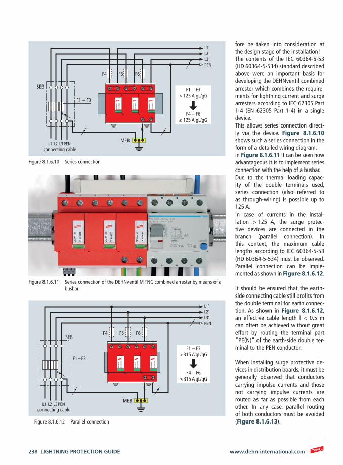
fore be taken into consideration at the design stage of the installation!The contents of the IEC 60364-5-53 (HD 60364-5-534) standard described above were an important basis for developing the DEHNventil combined arrester which combines the require-ments for lightning current and surge arresters according to IEC 62305 Part 1-4 (EN 62305 Part 1-4) in a single device. This allows series connection direct-ly via the device. Figure 8.1.6.10 shows such a series connection in the form of a detailed wiring diagram.In Figure 8.1.6.11 it can be seen how advantageous it is to implement series connection with the help of a busbar.Due to the thermal loading capac-ity of the double terminals used, series connection (also referred to as through-wiring) is possible up to 125 A.In case of currents in the instal-lation > 125 A, the surge protec-tive devices are connected in the branch (parallel connection). In this context, the maximum cable lengths according to IEC 60364-5-53 (HD 60364-5-534) must be observed. Parallel connection can be imple-mented as shown in Figure 8.1.6.12.
It should be ensured that the earth-side connecting cable still profits from the double terminal for earth connec-tion. As shown in Figure 8.1.6.12, an effective cable length l < 0.5 m can often be achieved without great effort by routing the terminal part “PE(N)” of the earth-side double ter-minal to the PEN conductor.
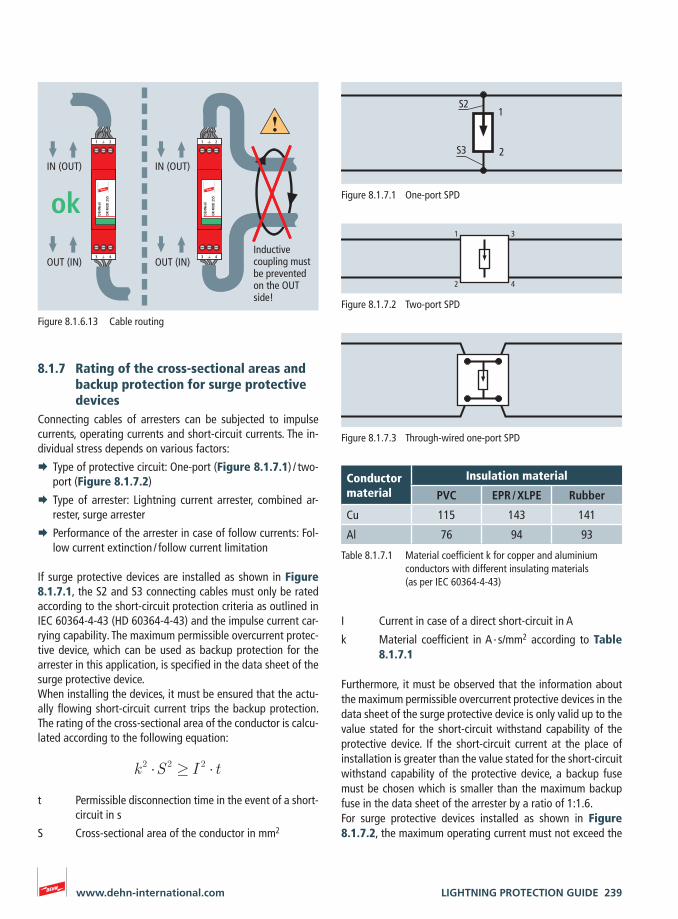
When installing surge protective de-vices in distribution boards, it must be generally observed that conductors carrying impulse currents and those not carrying impulse currents are routed as far as possible from each other. In any case, parallel routing of both conductors must be avoided (Figure 8.1.6.13).
DV
MO
D 2
55
DEH
Nve
ntil
DV
MO
D 2
55
DEH
Nve
ntil
DV
MO
D 2
55
DEH
Nve
ntil
L1 L2 L3L1' L2' L3'
PEN
L1'L2'L3'PEN
L1 L2 L3PEN
F4 F5 F6
F1 – F3
F1 – F3> 315 A gL/gG
F4 – F6≤ 315 A gL/gG
MEB
SEB
connecting cable
Figure 8.1.6.12 Parallel connection
DV
MO
D 2
55
DEH
Nve
ntil
DV
MO
D 2
55
DEH
Nve
ntil
DV
MO
D 2
55
DEH
Nve
ntil
L1 L2 L3L1' L2' L3'
PEN
L1'L2'L3'PEN
L1 L2 L3PEN
F4 F5 F6
F1 – F3
F1 – F3> 125 A gL/gG
F4 – F6≤ 125 A gL/gG
MEB
connecting cable
SEB
Figure 8.1.6.10 Series connection
Figure 8.1.6.11 Series connection of the DEHNventil M TNC combined arrester by means of a busbar
LIGHTNING PROTECTION GUIDE 239www.dehn-international.com
I Current in case of a direct short-circuit in A
k Material coefficient in A ∙ s/mm2 according to Table 8.1.7.1
Furthermore, it must be observed that the information about the maximum permissible overcurrent protective devices in the data sheet of the surge protective device is only valid up to the value stated for the short-circuit withstand capability of the protective device. If the short-circuit current at the place of installation is greater than the value stated for the short-circuit withstand capability of the protective device, a backup fuse must be chosen which is smaller than the maximum backup fuse in the data sheet of the arrester by a ratio of 1:1.6. For surge protective devices installed as shown in Figure 8.1.7.2, the maximum operating current must not exceed the
8.1.7 Rating of the cross-sectional areas and backup protection for surge protective devices
Connecting cables of arresters can be subjected to impulse currents, operating currents and short-circuit currents. The in-dividual stress depends on various factors:
¨ Type of protective circuit: One-port (Figure 8.1.7.1) / two-port (Figure 8.1.7.2)
¨ Type of arrester: Lightning current arrester, combined ar-rester, surge arrester
¨ Performance of the arrester in case of follow currents: Fol-low current extinction / follow current limitation
If surge protective devices are installed as shown in Figure 8.1.7.1, the S2 and S3 connecting cables must only be rated according to the short-circuit protection criteria as outlined in IEC 60364-4-43 (HD 60364-4-43) and the impulse current car-rying capability. The maximum permissible overcurrent protec-tive device, which can be used as backup protection for the arrester in this application, is specified in the data sheet of the surge protective device.When installing the devices, it must be ensured that the actu-ally flowing short-circuit current trips the backup protection. The rating of the cross-sectional area of the conductor is calcu-lated according to the following equation:
k 2 S 2 I 2 t
t Permissible disconnection time in the event of a short-circuit in s
S Cross-sectional area of the conductor in mm2
1
2
S2
S3
Figure 8.1.7.1 One-port SPD
3
4
1
2
Figure 8.1.7.2 Two-port SPD
Figure 8.1.7.3 Through-wired one-port SPD
Table 8.1.7.1 Material coefficient k for copper and aluminium conductors with different insulating materials (as per IEC 60364-4-43)
Conductor material
Insulation material
PVC EPR / XLPE Rubber
Cu 115 143 141
Al 76 94 93
1 2
DR
MO
D 2
55
DEH
Nra
il
3 4
1 2
DR
MO
D 2
55
DEH
Nra
il
3 4
IN (OUT)
OUT (IN)
IN (OUT)
OUT (IN)
okInductive coupling must be prevented on the OUT side!
Figure 8.1.6.13 Cable routing
240 LIGHTNING PROTECTION GUIDE www.dehn-international.com
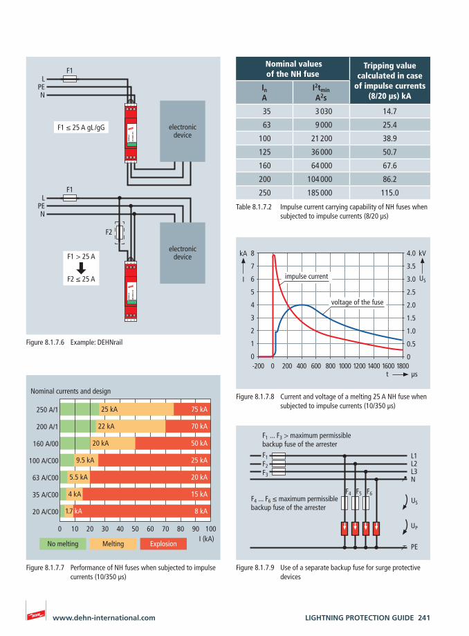
Field 1: No meltingThe energy injected into the fuse by the lightning impulse cur-rent is too low to melt the fuse.
Field 2: MeltingThe energy of the lightning impulse current is sufficient to melt the fuse and interrupt the current path by means of the fuse (Figure 8.1.7.8).It is characteristic of the performance of the fuse that the light-ning impulse current still flows unaffected by the performance of the fuse since it is injected. The fuse trips only after the light-ning impulse current has decayed. Thus, the fuses are not se-lective with respect to the disconnection of lightning impulse currents. Therefore, it must be ensured that the maximum permissible backup fuse according to the data sheet and / or installation instructions of the protective device is always used due to the impulse current behaviour.
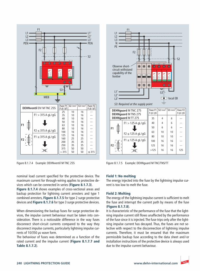
nominal load current specified for the protective device. The maximum current for through-wiring applies to protective de-vices which can be connected in series (Figure 8.1.7.3).Figure 8.1.7.4 shows examples of cross-sectional areas and backup protection for lightning current arresters and type 1 combined arresters, Figure 8.1.7.5 for type 2 surge protective devices and Figure 8.1.7.6 for type 3 surge protective devices.
When dimensioning the backup fuses for surge protective de-vices, the impulse current behaviour must be taken into con-sideration. There is a noticeable difference in the way fuses disconnect short-circuit currents compared to the way they disconnect impulse currents, particularly lightning impulse cur-rents of 10/350 μs wave form.The behaviour of fuses was determined as a function of the rated current and the impulse current (Figure 8.1.7.7 and Table 8.1.7.2).
L1 L2
DG
MO
D 2
75
DEH
Ngu
ard
DG
MO
D 2
75
DEH
Ngu
ard
L3
DG
MO
D 2
75
DEH
Ngu
ard
N
PE
DG
MO
D N
PE
DEH
Ngu
ard
DEHNguard M TNC 275DEHNguard M TNS 275DEHNguard M TT 275
F1
F1 > 125 A gL / gG
F2 ≤ 125 A gL / gG
Fuse F1 S2 / mm2 S3 / mm2 Fuse F2 A gL / gG A gL / gG
35 4 6 ---
40 4 6 ---
50 6 6 ---
63 10 10 ---
80 10 10 ---
100 16 16 ---
125 16 16 ---
>125 16 16 125
F2
F1 ≤ 125 A gL / gG
F2
F2
L1'L2'L3'
L1L2L3N
PE
F1
S2
S3
local EB
Observe short-circuit withstand capability of the busbar
S3: Required at the supply point
Figure 8.1.7.5 Example: DEHNguard M TNC/TNS/TT
DV
MO
D 2
55
DEH
Nve
ntil
DV
MO
D 2
55
DEH
Nve
ntil
DV
MO
D 2
55
DEH
Nve
ntil
L1 L2 L3L1' L2' L3'
PEN
F2
L1L2L3
PEN
L1'L2'L3'PEN
S3
F1
DEHNventil DV M TNC 255
F1
F2
F1 > 315 A gL / gG
F2 ≤ 315 A gL / gG
F1 ≤ 315 A gL / gG
F2
Fuse F1 S2 / mm2 S3 / mm2 Fuse F2 A gL / gG A gL / gG
25 10 16 --- 35 10 16 --- 40 10 16 --- 50 10 16 --- 63 10 16 --- 80 10 16 --- 100 16 16 --- 125 16 16 --- 160 25 25 --- 200 35 35 --- 250 35 35 --- 315 50 50 --- > 315 50 50 ≤ 315
S2
MEB
Figure 8.1.7.4 Example: DEHNventil M TNC 255
LIGHTNING PROTECTION GUIDE 241www.dehn-international.com
1 2
DR
MO
D 2
55
DEH
Nra
il
3 4
1 2
DR
MO
D 2
55
DEH
Nra
il
3 4
F1 > 25 A
F2 ≤ 25 A
F1
F1 ≤ 25 A gL /gG
F1
F2
LPEN
LPEN
electronic device
electronic device
Figure 8.1.7.6 Example: DEHNrail
0 10 20 30 40 50 60 70 80 90 100
250 A/1
200 A/1
160 A/00
100 A/C00
63 A/C00
35 A/C00
20 A/C00
I (kA)
25 kA 75 kA
22 kA 70 kA
20 kA 50 kA
25 kA
20 kA
4 kA 15 kA
8 kA
Nominal currents and design
9.5 kA
5.5 kA
1.7 kA
MeltingNo melting Explosion
Figure 8.1.7.7 Performance of NH fuses when subjected to impulse currents (10/350 µs)
8
7
6
5
4
3
2
1
0-200 0 200 400 600 800 1000 1200 1400 1600 1800
kA
I
t µs
kV
USimpulse current
voltage of the fuse
4.0
3.5
3.0
2.5
2.0
1.5
1.0
0.5
0
Figure 8.1.7.8 Current and voltage of a melting 25 A NH fuse when subjected to impulse currents (10/350 µs)
Table 8.1.7.2 Impulse current carrying capability of NH fuses when subjected to impulse currents (8/20 µs)
L1L2L3N
F1F2F3
PE
F4 F5 F6
US
UP
F1 ... F3 > maximum permissible backup fuse of the arrester
F4 ... F6 ≤ maximum permissible backup fuse of the arrester
Figure 8.1.7.9 Use of a separate backup fuse for surge protective devices
Nominal values of the NH fuse
Tripping value calculated in case
of impulse currents (8/20 µs) kA
InA
I2tminA2s
35 3 030 14.7
63 9 000 25.4
100 21 200 38.9
125 36 000 50.7
160 64 000 67.6
200 104 000 86.2
250 185 000 115.0
242 LIGHTNING PROTECTION GUIDE www.dehn-international.com
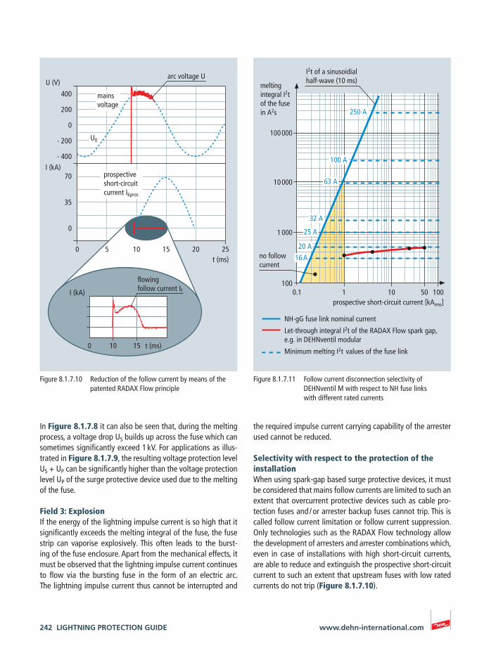
the required impulse current carrying capability of the arrester used cannot be reduced.
Selectivity with respect to the protection of the installationWhen using spark-gap based surge protective devices, it must be considered that mains follow currents are limited to such an extent that overcurrent protective devices such as cable pro-tection fuses and / or arrester backup fuses cannot trip. This is called follow current limitation or follow current suppression. Only technologies such as the RADAX Flow technology allow the development of arresters and arrester combinations which, even in case of installations with high short-circuit currents, are able to reduce and extinguish the prospective short-circuit current to such an extent that upstream fuses with low rated currents do not trip (Figure 8.1.7.10).
In Figure 8.1.7.8 it can also be seen that, during the melting process, a voltage drop US builds up across the fuse which can sometimes significantly exceed 1 kV. For applications as illus-trated in Figure 8.1.7.9, the resulting voltage protection level US + UP can be significantly higher than the voltage protection level UP of the surge protective device used due to the melting of the fuse.
Field 3: ExplosionIf the energy of the lightning impulse current is so high that it significantly exceeds the melting integral of the fuse, the fuse strip can vaporise explosively. This often leads to the burst-ing of the fuse enclosure. Apart from the mechanical effects, it must be observed that the lightning impulse current continues to flow via the bursting fuse in the form of an electric arc. The lightning impulse current thus cannot be interrupted and
100 000
10 000
1 000
1001 10 100
25 A
32 A
63 A
100 A
250 A
20 A
50
16 A
melting integral I2t of the fuse in A2s
0.1prospective short-circuit current [kArms]
no follow current
NH-gG fuse link nominal current
Let-through integral I2t of the RADAX Flow spark gap,e.g. in DEHNventil modular
Minimum melting I2t values of the fuse link
I2t of a sinusoidial half-wave (10 ms)
Figure 8.1.7.11 Follow current disconnection selectivity of DEHNventil M with respect to NH fuse links with different rated currents
400
200
0
- 200
- 400
U0
U (V)
70
35
0
0 5 10 15 20 25t (ms)
I (kA)
0 10 15 t (ms)
I (kA)
mainsvoltage
arc voltage U
prospectiveshort-circuitcurrent Ikpros
flowing follow current If
Figure 8.1.7.10 Reduction of the follow current by means of the patented RADAX Flow principle
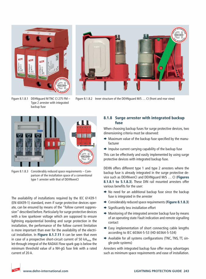
LIGHTNING PROTECTION GUIDE 243www.dehn-international.com
8.1.8 Surge arrester with integrated backup fuse
When choosing backup fuses for surge protective devices, two dimensioning criteria must be observed:
¨ Maximum value of the backup fuse specified by the manu-facturer
¨ Impulse current carrying capability of the backup fuse
This can be effectively and easily implemented by using surge protective devices with integrated backup fuse.
DEHN offers different type 1 and type 2 arresters where the backup fuse is already integrated in the surge protective de-vice such as DEHNvenCI and DEHNguard M/S … CI (Figures 8.1.8.1 to 5.1.8.3). These DIN rail mounted arresters offer various benefits for the user:
¨ No need for an additional backup fuse since the backup fuse is integrated in the arrester
¨ Considerably reduced space requirements (Figure 8.1.8.3)
¨ Significantly less installation effort
¨ Monitoring of the integrated arrester backup fuse by means of an operating state / fault indication and remote signalling contact
¨ Easy implementation of short connecting cable lengths according to IEC 60364-5-53 (HD 60364-5-534)
¨ Available for all systems configurations (TNC, TNS, TT, sin-gle-pole systems)
Arresters with integrated backup fuse offer many advantages such as minimum space requirements and ease of installation.
The availability of installations required by the IEC 61439-1 (EN 60439-1) standard, even if surge protective devices oper-ate, can be ensured by means of the “follow current suppres-sion” described before. Particularly for surge protective devices with a low sparkover voltage which are supposed to ensure lightning equipotential bonding and surge protection in the installation, the performance of the follow current limitation is more important than ever for the availability of the electri-cal installation. In Figure 8.1.7.11 it can be seen that even in case of a prospective short-circuit current of 50 kArms, the let-through integral of the RADAX Flow spark gap is below the minimum threshold value of a NH-gG fuse link with a rated current of 20 A.
Figure 8.1.8.1 DEHNguard M TNC CI 275 FM – Type 2 arrester with integrated backup fuse
Figure 8.1.8.2 Inner structure of the DEHNguard M/S … CI (front and rear view)
Figure 8.1.8.3 Considerably reduced space requirements – Com-parison of the installation space of a conventional type 1 arrester with that of DEHNvenCI
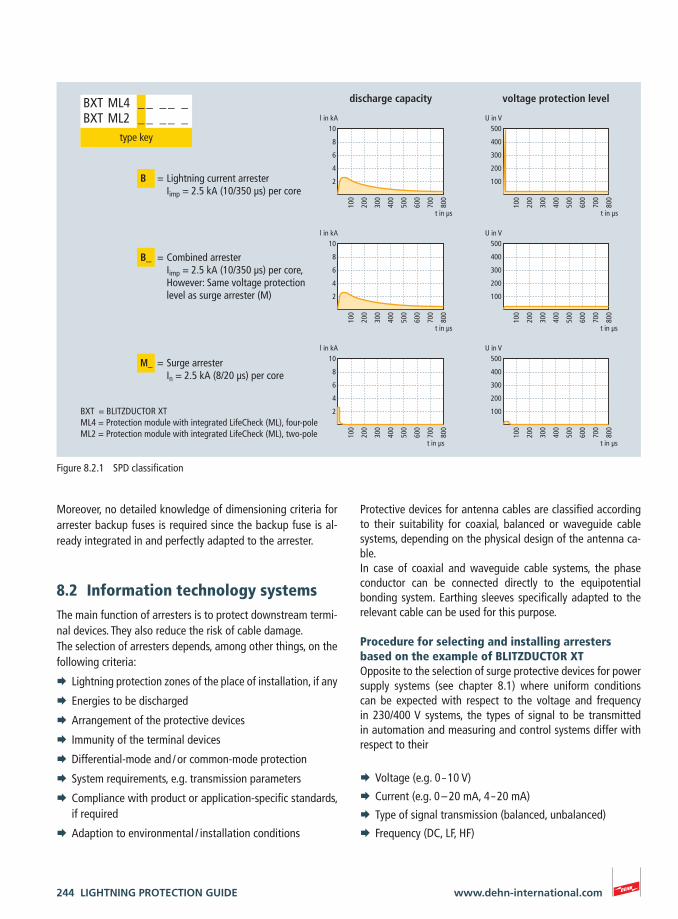
244 LIGHTNING PROTECTION GUIDE www.dehn-international.com
Protective devices for antenna cables are classified according to their suitability for coaxial, balanced or waveguide cable systems, depending on the physical design of the antenna ca-ble.In case of coaxial and waveguide cable systems, the phase conductor can be connected directly to the equipotential bonding system. Earthing sleeves specifically adapted to the relevant cable can be used for this purpose.
Procedure for selecting and installing arresters based on the example of BLITZDUCTOR XTOpposite to the selection of surge protective devices for power supply systems (see chapter 8.1) where uniform conditions can be expected with respect to the voltage and frequency in 230/400 V systems, the types of signal to be transmitted in automation and measuring and control systems differ with respect to their
¨ Voltage (e.g. 0 – 10 V)
¨ Current (e.g. 0 – 20 mA, 4 – 20 mA)
¨ Type of signal transmission (balanced, unbalanced)
¨ Frequency (DC, LF, HF)
Moreover, no detailed knowledge of dimensioning criteria for arrester backup fuses is required since the backup fuse is al-ready integrated in and perfectly adapted to the arrester.
8.2 Information technology systemsThe main function of arresters is to protect downstream termi-nal devices. They also reduce the risk of cable damage.The selection of arresters depends, among other things, on the following criteria:
¨ Lightning protection zones of the place of installation, if any
¨ Energies to be discharged
¨ Arrangement of the protective devices
¨ Immunity of the terminal devices
¨ Differential-mode and / or common-mode protection
¨ System requirements, e.g. transmission parameters
¨ Compliance with product or application-specific standards, if required
¨ Adaption to environmental / installation conditions
U in V500
400
300
200
100
100
200
300
400
500
600
700
800
t in µs
U in V500
400
300
200
100
100
200
300
400
500
600
700
800
t in µs
U in V500
400
300
200
100
100
200
300
400
500
600
700
800
t in µs
l in kA10
8
6
4
2
100
200
300
400
500
600
700
800
t in µs
l in kA10
8
6
4
2
100
200
300
400
500
600
700
800
t in µs
l in kA10
8
6
4
2
100
200
300
400
500
600
700
800
t in µs
BXT ML4 _ _ _ _ _BXT ML2 _ _ _ _ _
type key
B = Lightning current arrester Iimp = 2.5 kA (10/350 µs) per core
B_ = Combined arrester Iimp = 2.5 kA (10/350 µs) per core,
However: Same voltage protection level as surge arrester (M)
M_ = Surge arrester In = 2.5 kA (8/20 µs) per core
voltage protection leveldischarge capacity
BXT = BLITZDUCTOR XTML4 = Protection module with integrated LifeCheck (ML), four-poleML2 = Protection module with integrated LifeCheck (ML), two-pole
Figure 8.2.1 SPD classification
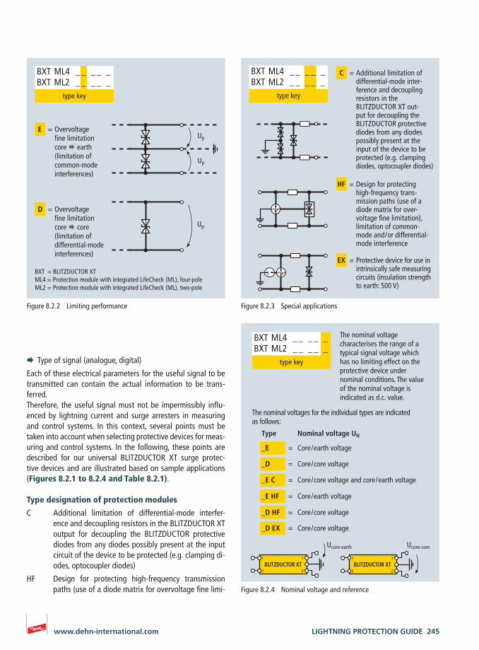
LIGHTNING PROTECTION GUIDE 245www.dehn-international.com
¨ Type of signal (analogue, digital)
Each of these electrical parameters for the useful signal to be transmitted can contain the actual information to be trans-ferred. Therefore, the useful signal must not be impermissibly influ-enced by lightning current and surge arresters in measuring and control systems. In this context, several points must be taken into account when selecting protective devices for meas-uring and control systems. In the following, these points are described for our universal BLITZDUCTOR XT surge protec-tive devices and are illustrated based on sample applications (Figures 8.2.1 to 8.2.4 and Table 8.2.1).
Type designation of protection modules
C Additional limitation of differential-mode interfer-ence and decoupling resistors in the BLITZDUCTOR XT output for decoupling the BLITZDUCTOR protective diodes from any diodes possibly present at the input circuit of the device to be protected (e.g. clamping di-odes, optocoupler diodes)
HF Design for protecting high-frequency transmission paths (use of a diode matrix for overvoltage fine limi-
Up
Up
Up
E = Overvoltage fine limitation core earth(limitation of common-mode interferences)
D = Overvoltage fine limitation core core(limitation of differential-mode interferences)
BXT ML4 _ _ _ _ _BXT ML2 _ _ _ _ _
type key
BXT = BLITZDUCTOR XTML4 = Protection module with integrated LifeCheck (ML), four-poleML2 = Protection module with integrated LifeCheck (ML), two-pole
Figure 8.2.2 Limiting performance
HF = Design for protecting high-frequency trans-mission paths (use of a diode matrix for over-voltage fine limitation), limitation of common-mode and / or differential-mode interference
EX = Protective device for use in intrinsically safe measuring circuits (insulation strength to earth: 500 V)
BXT ML4 _ _ _ _ _BXT ML2 _ _ _ _ _
type key
C = Additional limitation of differential-mode inter-ference and decoupling resistors in the BLITZDUCTOR XT out-put for decoupling the BLITZDUCTOR protective diodes from any diodes possibly present at the
input of the device to be protected (e.g. clamping diodes, optocoupler diodes)
Figure 8.2.3 Special applications
BLITZDUCTOR XT BLITZDUCTOR XT1
2
1‘
2‘
1
2
1‘
2‘
_E = Core / earth voltage
The nominal voltage characterises the range of a typical signal voltage which has no limiting effect on the protective device under nominal conditions. The value of the nominal voltage is indicated as d.c. value.
_D = Core / core voltage
_E C = Core / core voltage and core / earth voltage
_E HF = Core / earth voltage
_D HF = Core / core voltage
_D EX = Core / core voltage
Ucore-earth Ucore-core
Type Nominal voltage UN
BXT ML4 _ _ _ _ _BXT ML2 _ _ _ _ _
type key
The nominal voltages for the individual types are indicated as follows:
Figure 8.2.4 Nominal voltage and reference
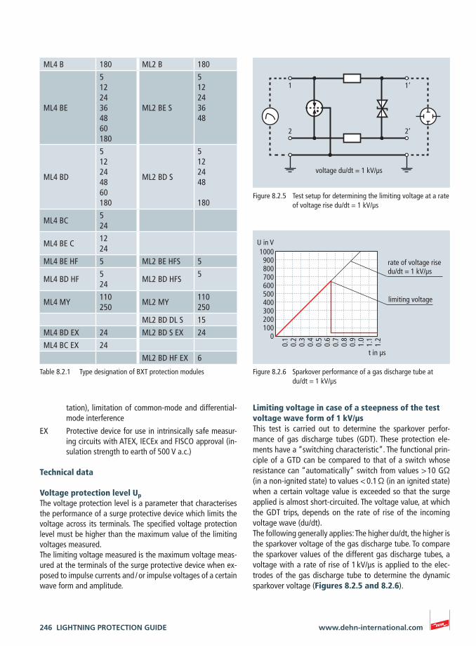
246 LIGHTNING PROTECTION GUIDE www.dehn-international.com
Limiting voltage in case of a steepness of the test voltage wave form of 1 kV/μsThis test is carried out to determine the sparkover perfor-mance of gas discharge tubes (GDT). These protection ele-ments have a “switching characteristic”. The functional prin-ciple of a GTD can be compared to that of a switch whose resistance can “automatically“ switch from values > 10 GΩ (in a non-ignited state) to values < 0.1 Ω (in an ignited state) when a certain voltage value is exceeded so that the surge applied is almost short-circuited. The voltage value, at which the GDT trips, depends on the rate of rise of the incoming voltage wave (du/dt).The following generally applies: The higher du/dt, the higher is the sparkover voltage of the gas discharge tube. To compare the sparkover values of the different gas discharge tubes, a voltage with a rate of rise of 1 kV/μs is applied to the elec-trodes of the gas discharge tube to determine the dynamic sparkover voltage (Figures 8.2.5 and 8.2.6).
tation), limitation of common-mode and differential-mode interference
EX Protective device for use in intrinsically safe measur-ing circuits with ATEX, IECEx and FISCO approval (in-sulation strength to earth of 500 V a.c.)
Technical data
Voltage protection level UpThe voltage protection level is a parameter that characterises the performance of a surge protective device which limits the voltage across its terminals. The specified voltage protection level must be higher than the maximum value of the limiting voltages measured.The limiting voltage measured is the maximum voltage meas-ured at the terminals of the surge protective device when ex-posed to impulse currents and / or impulse voltages of a certain wave form and amplitude.
1
2
1‘
2‘
voltage du/dt = 1 kV/µs
Figure 8.2.5 Test setup for determining the limiting voltage at a rate of voltage rise du/dt = 1 kV/µs
U in V1000900800700600500400300200100
0
t in µs
rate of voltage rise du/dt = 1 kV/µs
limiting voltage
0.1
0.2
0.3
0.4
0.5
0.6
0.7
0.8
0.9
1.0
1.1
1.2
Figure 8.2.6 Sparkover performance of a gas discharge tube at du/dt = 1 kV/µs
Table 8.2.1 Type designation of BXT protection modules
ML4 B 180 ML2 B 180
ML4 BE
51224364860180
ML2 BE S
512243648
ML4 BD
512244860180
ML2 BD S
5122448 180
ML4 BC524
ML4 BE C1224
ML4 BE HF 5 ML2 BE HFS 5
ML4 BD HF524
ML2 BD HFS5
ML4 MY110250
ML2 MY110250
ML2 BD DL S 15
ML4 BD EX 24 ML2 BD S EX 24
ML4 BC EX 24
ML2 BD HF EX 6
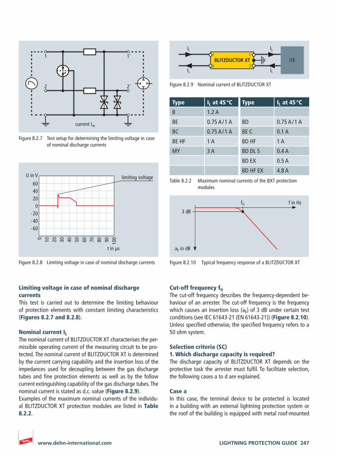
LIGHTNING PROTECTION GUIDE 247www.dehn-international.com
Cut-off frequency fGThe cut-off frequency describes the frequency-dependent be-haviour of an arrester. The cut-off frequency is the frequency which causes an insertion loss (aE) of 3 dB under certain test conditions (see IEC 61643-21 (EN 61643-21)) (Figure 8.2.10). Unless specified otherwise, the specified frequency refers to a 50 ohm system.
Selection criteria (SC)1. Which discharge capacity is required?The discharge capacity of BLITZDUCTOR XT depends on the protective task the arrester must fulfil. To facilitate selection, the following cases a to d are explained.
Case aIn this case, the terminal device to be protected is located in a building with an external lightning protection system or the roof of the building is equipped with metal roof-mounted
Limiting voltage in case of nominal discharge currentsThis test is carried out to determine the limiting behaviour of protection elements with constant limiting characteristics (Figures 8.2.7 and 8.2.8).
Nominal current ILThe nominal current of BLITZDUCTOR XT characterises the per-missible operating current of the measuring circuit to be pro-tected. The nominal current of BLITZDUCTOR XT is determined by the current carrying capability and the insertion loss of the impedances used for decoupling between the gas discharge tubes and fine protection elements as well as by the follow current extinguishing capability of the gas discharge tubes. The nominal current is stated as d.c. value (Figure 8.2.9).Examples of the maximum nominal currents of the individu-al BLITZDUCTOR XT protection modules are listed in Table 8.2.2.
1
2
1‘
2‘
current Isn
Figure 8.2.7 Test setup for determining the limiting voltage in case of nominal discharge currents
U in V
604020
0- 20- 40- 60
0 10 20 30 40 50 60 70 80 90 100
t in µs
limiting voltage
Figure 8.2.8 Limiting voltage in case of nominal discharge currents
BLITZDUCTOR XT
IL
IL
IL
ITE
IL
1
2
1‘
2‘
Figure 8.2.9 Nominal current of BLITZDUCTOR XT
Table 8.2.2 Maximum nominal currents of the BXT protection modules
f in Hz
3 dB
fG
aE in dB
Figure 8.2.10 Typical frequency response of a BLITZDUCTOR XT
Type IL at 45 °C Type IL at 45 °C
B 1.2 A
BE 0.75 A / 1 A BD 0.75 A / 1 A
BC 0.75 A / 1 A BE C 0.1 A
BE HF 1 A BD HF 1 A
MY 3 A BD DL S 0.4 A
BD EX 0.5 A
BD HF EX 4.8 A
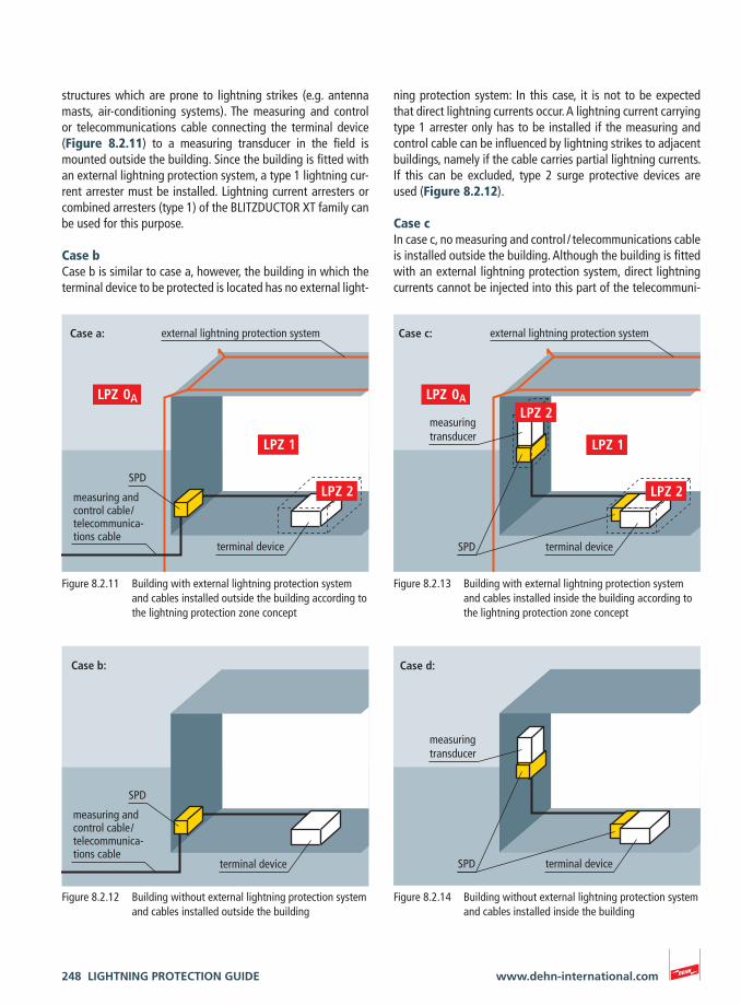
248 LIGHTNING PROTECTION GUIDE www.dehn-international.com
ning protection system: In this case, it is not to be expected that direct lightning currents occur. A lightning current carrying type 1 arrester only has to be installed if the measuring and control cable can be influenced by lightning strikes to adjacent buildings, namely if the cable carries partial lightning currents. If this can be excluded, type 2 surge protective devices are used (Figure 8.2.12).
Case cIn case c, no measuring and control / telecommunications cable is installed outside the building. Although the building is fitted with an external lightning protection system, direct lightning currents cannot be injected into this part of the telecommuni-
structures which are prone to lightning strikes (e.g. antenna masts, air-conditioning systems). The measuring and control or telecommunications cable connecting the terminal device (Figure 8.2.11) to a measuring transducer in the field is mounted outside the building. Since the building is fitted with an external lightning protection system, a type 1 lightning cur-rent arrester must be installed. Lightning current arresters or combined arresters (type 1) of the BLITZDUCTOR XT family can be used for this purpose.
Case bCase b is similar to case a, however, the building in which the terminal device to be protected is located has no external light-
terminal device
Case b:
measuring andcontrol cable / telecommunica-tions cable
SPD
Figure 8.2.12 Building without external lightning protection system and cables installed outside the building
measuring transducer
terminal deviceSPD
external lightning protection systemCase c:
Figure 8.2.13 Building with external lightning protection system and cables installed inside the building according to the lightning protection zone concept
terminal deviceSPD
Case d:
measuring transducer
Figure 8.2.14 Building without external lightning protection system and cables installed inside the building
measuring andcontrol cable / telecommunica-tions cable
terminal device
SPD
external lightning protection systemCase a:
Figure 8.2.11 Building with external lightning protection system and cables installed outside the building according to the lightning protection zone concept
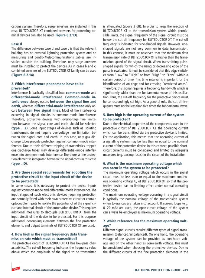
LIGHTNING PROTECTION GUIDE 249www.dehn-international.com
is attenuated (above 3 dB). In order to keep the reaction of BLITZDUCTOR XT to the transmission system within permis-sible limits, the signal frequency of the signal circuit must be below the cut-off frequency for BLITZDUCTOR XT. The cut-off frequency is indicated for sine-shaped signals. However, sine-shaped signals are not very common in data transmission. In this context, it must be observed that the maximum data transmission rate of BLITZDUCTOR XT is higher than the trans-mission speed of the signal circuit. When transmitting pulse-shaped signals for which the rising or decreasing edge of the pulse is evaluated, it must be considered that this edge switch-es from “Low” to “High” or from “High” to “Low” within a certain period of time. This time interval is important for the identification of an edge and for crossing “restricted areas“. Therefore, this signal requires a frequency bandwidth which is significantly wider than the fundamental wave of this oscilla-tion. Thus, the cut-off frequency for the protective device must be correspondingly set high. As a general rule, the cut-off fre-quency must not be less than five times the fundamental wave.
5. How high is the operating current of the system to be protected?Due to the electrical properties of the components used in the protective circuit of BLITZDUCTOR XT, the operating current which can be transmitted via the protective device is limited. For the application, this means that the operating current of a signalling system may be less than or equal to the nominal current of the protective device. In this context, possible short-circuit currents must be considered and limited by adequate measures (e.g. backup fuses) in the circuit of the installation.
6. What is the maximum operating voltage which can occur in the system to be protected?The maximum operating voltage which occurs in the signal circuit must be less than or equal to the maximum continu-ous operating voltage Uc of BLITZDUCTOR XT so that the pro-tective device has no limiting effect under normal operating conditions.The maximum operating voltage occurring in a signal circuit is typically the nominal voltage of the transmission system when tolerances are taken into account. If current loops (e.g. 0 – 20 mA) are used, the open-circuit voltage of the system can always be employed as maximum operating voltage.
7. Which reference has the maximum operating volt-age?Different signal circuits require different types of signal trans-mission (balanced / unbalanced). On one hand, the operating voltage of the system can be provided as core / core volt-age and on the other hand as core / earth voltage. This must be considered when choosing the protective devices. Due to the different circuits of the fine protection elements in the
cations system. Therefore, surge arresters are installed in this case. BLITZDUCTOR XT combined arresters for protecting ter-minal devices can also be used (Figure 8.2.13).
Case dThe difference between case d and case c is that the relevant building has no external lightning protection system and no measuring and control / telecommunications cables are in-stalled outside the building. Therefore, only surge arresters must be installed to protect the devices. As in cases b and c, combined arresters of the BLITZDUCTOR XT family can be used (Figure 8.2.14).
2. Which interference phenomena have to be prevented?Interference is basically classified into common-mode and differential-mode interference. Common-mode in-terference always occurs between the signal line and earth, whereas differential-mode interference only oc-curs between two signal lines. Most of the interference occurring in signal circuits is common-mode interference. Therefore, protective devices with overvoltage fine limita-tion between the signal core and earth should be selected (type …E). Some input stages of devices such as isolating transformers do not require overvoltage fine limitation be-tween the signal core and earth. In this case, only gas dis-charge tubes provide protection against common-mode inter-ference. Due to their different tripping characteristics, tripped gas discharge tubes may develop differential-mode interfer-ence into common-mode interference. Therefore, a fine protec-tion element is integrated between the signal cores in this case (type ...D).
3. Are there special requirements for adopting the protective circuit to the input circuit of the device to be protected?In some cases, it is necessary to protect the device inputs against common-mode and differential-mode interference. The input stages of such electronic devices requiring protection are normally fitted with their own protective circuit or contain optocoupler inputs to isolate the potential of of the signal cir-cuit and internal circuit of the automation device. This requires additional measures to decouple BLITZDUCTOR XT from the input circuit of the device to be protected. For this purpose, additional decoupling elements between the fine protection elements and output terminals of BLITZDUCTOR XT are used.
4. How high is the signal frequency / data trans- mission rate which must be transmitted?The protective circuit of BLITZDUCTOR XT has low-pass char-acteristics. The cut-off frequency indicates the frequency value above which the amplitude of the signal to be transmitted
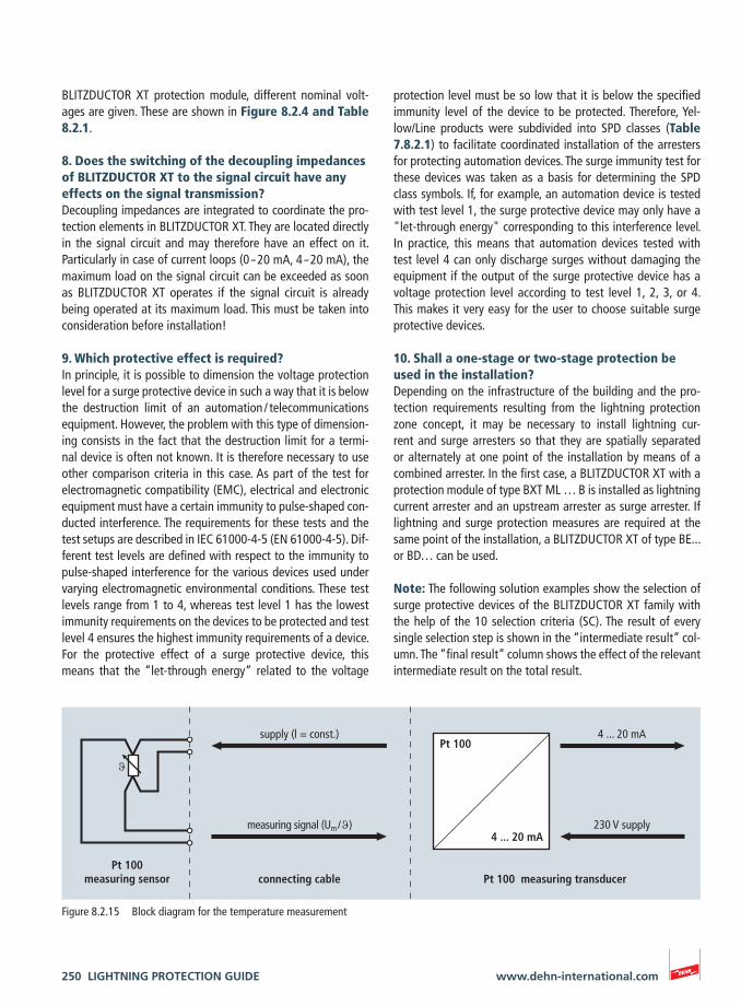
250 LIGHTNING PROTECTION GUIDE www.dehn-international.com
protection level must be so low that it is below the specified immunity level of the device to be protected. Therefore, Yel-low/Line products were subdivided into SPD classes (Table 7.8.2.1) to facilitate coordinated installation of the arresters for protecting automation devices. The surge immunity test for these devices was taken as a basis for determining the SPD class symbols. If, for example, an automation device is tested with test level 1, the surge protective device may only have a "let-through energy" corresponding to this interference level. In practice, this means that automation devices tested with test level 4 can only discharge surges without damaging the equipment if the output of the surge protective device has a voltage protection level according to test level 1, 2, 3, or 4. This makes it very easy for the user to choose suitable surge protective devices.
10. Shall a one-stage or two-stage protection be used in the installation?Depending on the infrastructure of the building and the pro-tection requirements resulting from the lightning protection zone concept, it may be necessary to install lightning cur-rent and surge arresters so that they are spatially separated or alternately at one point of the installation by means of a combined arrester. In the first case, a BLITZDUCTOR XT with a protection module of type BXT ML … B is installed as lightning current arrester and an upstream arrester as surge arrester. If lightning and surge protection measures are required at the same point of the installation, a BLITZDUCTOR XT of type BE... or BD… can be used.
Note: The following solution examples show the selection of surge protective devices of the BLITZDUCTOR XT family with the help of the 10 selection criteria (SC). The result of every single selection step is shown in the “intermediate result” col-umn. The “final result” column shows the effect of the relevant intermediate result on the total result.
BLITZDUCTOR XT protection module, different nominal volt-ages are given. These are shown in Figure 8.2.4 and Table 8.2.1.
8. Does the switching of the decoupling impedances of BLITZDUCTOR XT to the signal circuit have any effects on the signal transmission?Decoupling impedances are integrated to coordinate the pro-tection elements in BLITZDUCTOR XT. They are located directly in the signal circuit and may therefore have an effect on it. Particularly in case of current loops (0 – 20 mA, 4 – 20 mA), the maximum load on the signal circuit can be exceeded as soon as BLITZDUCTOR XT operates if the signal circuit is already being operated at its maximum load. This must be taken into consideration before installation!
9. Which protective effect is required?In principle, it is possible to dimension the voltage protection level for a surge protective device in such a way that it is below the destruction limit of an automation / telecommunications equipment. However, the problem with this type of dimension-ing consists in the fact that the destruction limit for a termi-nal device is often not known. It is therefore necessary to use other comparison criteria in this case. As part of the test for electromagnetic compatibility (EMC), electrical and electronic equipment must have a certain immunity to pulse-shaped con-ducted interference. The requirements for these tests and the test setups are described in IEC 61000-4-5 (EN 61000-4-5). Dif-ferent test levels are defined with respect to the immunity to pulse-shaped interference for the various devices used under varying electromagnetic environmental conditions. These test levels range from 1 to 4, whereas test level 1 has the lowest immunity requirements on the devices to be protected and test level 4 ensures the highest immunity requirements of a device.For the protective effect of a surge protective device, this means that the “let-through energy“ related to the voltage
supply (l = const.)
measuring signal (Um / ϑ)
Pt 100measuring sensor connecting cable Pt 100 measuring transducer
ϑ
Pt 100
4 ... 20 mA
4 ... 20 mA
230 V supply
Figure 8.2.15 Block diagram for the temperature measurement
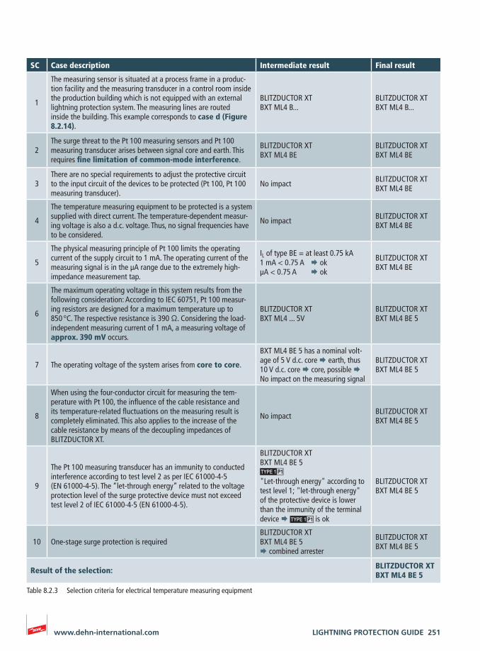
LIGHTNING PROTECTION GUIDE 251www.dehn-international.com
Table 8.2.3 Selection criteria for electrical temperature measuring equipment
SC Case description Intermediate result Final result
1
The measuring sensor is situated at a process frame in a produc-tion facility and the measuring transducer in a control room inside the production building which is not equipped with an external lightning protection system. The measuring lines are routed inside the building. This example corresponds to case d (Figure 8.2.14).
BLITZDUCTOR XTBXT ML4 B...
BLITZDUCTOR XTBXT ML4 B...
2The surge threat to the Pt 100 measuring sensors and Pt 100 measuring transducer arises between signal core and earth. This requires fine limitation of common-mode interference.
BLITZDUCTOR XTBXT ML4 BE
BLITZDUCTOR XTBXT ML4 BE
3There are no special requirements to adjust the protective circuit to the input circuit of the devices to be protected (Pt 100, Pt 100 measuring transducer).
No impact BLITZDUCTOR XTBXT ML4 BE
4
The temperature measuring equipment to be protected is a system supplied with direct current. The temperature-dependent measur-ing voltage is also a d.c. voltage. Thus, no signal frequencies have to be considered.
No impact BLITZDUCTOR XTBXT ML4 BE
5
The physical measuring principle of Pt 100 limits the operating current of the supply circuit to 1 mA. The operating current of the measuring signal is in the µA range due to the extremely high-impedance measurement tap.
IL of type BE = at least 0.75 kA1 mA < 0.75 A ¨ okµA < 0.75 A ¨ ok
BLITZDUCTOR XTBXT ML4 BE
6
The maximum operating voltage in this system results from the following consideration: According to IEC 60751, Pt 100 measur-ing resistors are designed for a maximum temperature up to 850 °C. The respective resistance is 390 Ω. Considering the load-independent measuring current of 1 mA, a measuring voltage of approx. 390 mV occurs.
BLITZDUCTOR XTBXT ML4 ... 5V
BLITZDUCTOR XTBXT ML4 BE 5
7 The operating voltage of the system arises from core to core.
BXT ML4 BE 5 has a nominal volt-age of 5 V d.c. core ¨ earth, thus 10 V d.c. core ¨ core, possible ¨ No impact on the measuring signal
BLITZDUCTOR XTBXT ML4 BE 5
8
When using the four-conductor circuit for measuring the tem-perature with Pt 100, the influence of the cable resistance and its temperature-related fluctuations on the measuring result is completely eliminated. This also applies to the increase of the cable resistance by means of the decoupling impedances of BLITZDUCTOR XT.
No impact BLITZDUCTOR XTBXT ML4 BE 5
9
The Pt 100 measuring transducer has an immunity to conducted interference according to test level 2 as per IEC 61000-4-5 (EN 61000-4-5). The “let-through energy” related to the voltage protection level of the surge protective device must not exceed test level 2 of IEC 61000-4-5 (EN 61000-4-5).
BLITZDUCTOR XTBXT ML4 BE 5
"Let-through energy" according to test level 1; "let-through energy" of the protective device is lower than the immunity of the terminal device ¨ is ok
BLITZDUCTOR XTBXT ML4 BE 5
10 One-stage surge protection is requiredBLITZDUCTOR XTBXT ML4 BE 5¨ combined arrester
BLITZDUCTOR XTBXT ML4 BE 5
Result of the selection: BLITZDUCTOR XTBXT ML4 BE 5
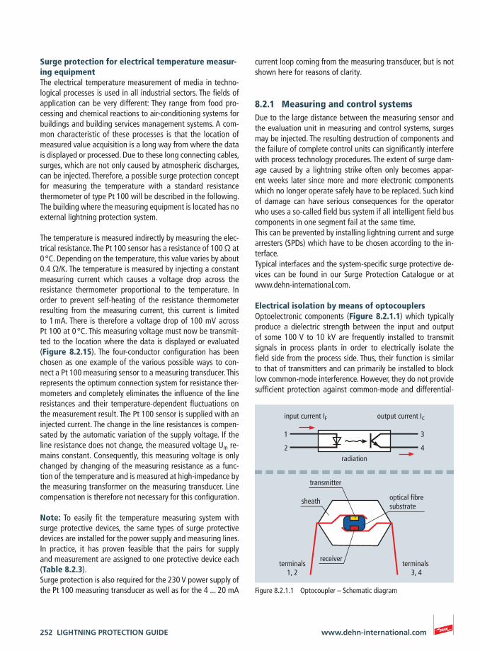
252 LIGHTNING PROTECTION GUIDE www.dehn-international.com
current loop coming from the measuring transducer, but is not shown here for reasons of clarity.
8.2.1 Measuring and control systemsDue to the large distance between the measuring sensor and the evaluation unit in measuring and control systems, surges may be injected. The resulting destruction of components and the failure of complete control units can significantly interfere with process technology procedures. The extent of surge dam-age caused by a lightning strike often only becomes appar-ent weeks later since more and more electronic components which no longer operate safely have to be replaced. Such kind of damage can have serious consequences for the operator who uses a so-called field bus system if all intelligent field bus components in one segment fail at the same time.This can be prevented by installing lightning current and surge arresters (SPDs) which have to be chosen according to the in-terface.Typical interfaces and the system-specific surge protective de-vices can be found in our Surge Protection Catalogue or at www.dehn-international.com.
Electrical isolation by means of optocouplersOptoelectronic components (Figure 8.2.1.1) which typically produce a dielectric strength between the input and output of some 100 V to 10 kV are frequently installed to transmit signals in process plants in order to electrically isolate the field side from the process side. Thus, their function is similar to that of transmitters and can primarily be installed to block low common-mode interference. However, they do not provide sufficient protection against common-mode and differential-
Surge protection for electrical temperature measur-ing equipmentThe electrical temperature measurement of media in techno-logical processes is used in all industrial sectors. The fields of application can be very different: They range from food pro-cessing and chemical reactions to air-conditioning systems for buildings and building services management systems. A com-mon characteristic of these processes is that the location of measured value acquisition is a long way from where the data is displayed or processed. Due to these long connecting cables, surges, which are not only caused by atmospheric discharges, can be injected. Therefore, a possible surge protection concept for measuring the temperature with a standard resistance thermometer of type Pt 100 will be described in the following. The building where the measuring equipment is located has no external lightning protection system.
The temperature is measured indirectly by measuring the elec-trical resistance. The Pt 100 sensor has a resistance of 100 Ω at 0 °C. Depending on the temperature, this value varies by about 0.4 Ω/K. The temperature is measured by injecting a constant measuring current which causes a voltage drop across the resistance thermometer proportional to the temperature. In order to prevent self-heating of the resistance thermometer resulting from the measuring current, this current is limited to 1 mA. There is therefore a voltage drop of 100 mV across Pt 100 at 0 °C. This measuring voltage must now be transmit-ted to the location where the data is displayed or evaluated (Figure 8.2.15). The four-conductor configuration has been chosen as one example of the various possible ways to con-nect a Pt 100 measuring sensor to a measuring transducer. This represents the optimum connection system for resistance ther-mometers and completely eliminates the influence of the line resistances and their temperature-dependent fluctuations on the measurement result. The Pt 100 sensor is supplied with an injected current. The change in the line resistances is compen-sated by the automatic variation of the supply voltage. If the line resistance does not change, the measured voltage Um re-mains constant. Consequently, this measuring voltage is only changed by changing of the measuring resistance as a func-tion of the temperature and is measured at high-impedance by the measuring transformer on the measuring transducer. Line compensation is therefore not necessary for this configuration.
Note: To easily fit the temperature measuring system with surge protective devices, the same types of surge protective devices are installed for the power supply and measuring lines. In practice, it has proven feasible that the pairs for supply and measurement are assigned to one protective device each (Table 8.2.3).Surge protection is also required for the 230 V power supply of the Pt 100 measuring transducer as well as for the 4 ... 20 mA
1
2
3
4
input current IF output current IC
radiation
transmitter
receiver
optical fibresubstrate
sheath
terminals1, 2
terminals 3, 4
Figure 8.2.1.1 Optocoupler – Schematic diagram
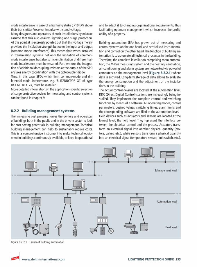
LIGHTNING PROTECTION GUIDE 253www.dehn-international.com
and to adapt it to changing organisational requirements, thus facilitating optimum management which increases the profit-ability of a property.
Building automation (BA) has grown out of measuring and control systems on the one hand, and centralised instrumenta-tion and control on the other hand. The function of building au-tomation is to automate all technical processes in the building. Therefore, the complete installation comprising room automa-tion, the M-bus measuring system and the heating, ventilation, air-conditioning and alarm system are networked via powerful computers on the management level (Figure 8.2.2.1) where data is archived. Long-term storage of data allows to evaluate the energy consumption and the adjustment of the installa-tions in the building.The actual control devices are located at the automation level. DDC (Direct Digital Control) stations are increasingly being in-stalled. They implement the complete control and switching functions by means of a software. All operating modes, control parameters, desired values, switching times, alarm limits and the corresponding software are filed at the automation level.Field devices such as actuators and sensors are located at the lowest level, the field level. They represent the interface be-tween the electrical control and the process. Actuators trans-form an electrical signal into another physical quantity (mo-tors, valves, etc.), while sensors transform a physical quantity into an electrical signal (temperature sensor, limit switch, etc.).
mode interference in case of a lightning strike (> 10 kV) above their transmitter / receiver impulse withstand voltage.Many designers and operators of such installations by mistake assume that this also ensures lightning and surge protection. At this point, it is expressly pointed out that this voltage merely provides the insulation strength between the input and output (common-mode interference). This means that, when installed in transmission systems, not only the limitation of common-mode interference, but also sufficient limitation of differential-mode interference must be ensured. Furthermore, the integra-tion of additional decoupling resistors at the output of the SPD ensures energy coordination with the optocoupler diode.Thus, in this case, SPDs which limit common-mode and dif-ferential-mode interference, e.g. BLITZDUCTOR XT of type BXT ML BE C 24, must be installed.More detailed information on the application-specific selection of surge protective devices for measuring and control systems can be found in chapter 9.
8.2.2 Building management systemsThe increasing cost pressure forces the owners and operators of buildings both in the public and in the private sector to look for cost saving potentials in building management. Technical building management can help to sustainably reduce costs. This is a comprehensive instrument to make technical equip-ment in buildings continuously available, to keep it operational
Management level
Automation level
Field level
Figure 8.2.2.1 Levels of building automation
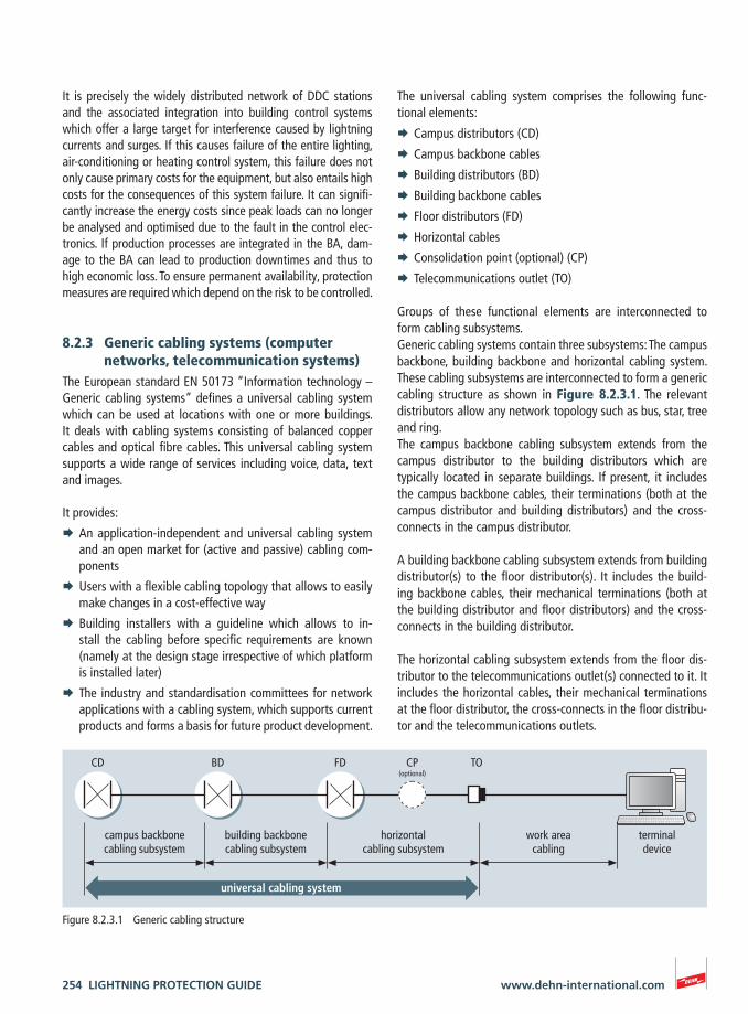
254 LIGHTNING PROTECTION GUIDE www.dehn-international.com
The universal cabling system comprises the following func-tional elements:
¨ Campus distributors (CD)
¨ Campus backbone cables
¨ Building distributors (BD)
¨ Building backbone cables
¨ Floor distributors (FD)
¨ Horizontal cables
¨ Consolidation point (optional) (CP)
¨ Telecommunications outlet (TO)
Groups of these functional elements are interconnected to form cabling subsystems.Generic cabling systems contain three subsystems: The campus backbone, building backbone and horizontal cabling system. These cabling subsystems are interconnected to form a generic cabling structure as shown in Figure 8.2.3.1. The relevant distributors allow any network topology such as bus, star, tree and ring.The campus backbone cabling subsystem extends from the campus distributor to the building distributors which are typically located in separate buildings. If present, it includes the campus backbone cables, their terminations (both at the campus distributor and building distributors) and the cross-connects in the campus distributor.
A building backbone cabling subsystem extends from building distributor(s) to the floor distributor(s). It includes the build-ing backbone cables, their mechanical terminations (both at the building distributor and floor distributors) and the cross-connects in the building distributor.
The horizontal cabling subsystem extends from the floor dis-tributor to the telecommunications outlet(s) connected to it. It includes the horizontal cables, their mechanical terminations at the floor distributor, the cross-connects in the floor distribu-tor and the telecommunications outlets.
It is precisely the widely distributed network of DDC stations and the associated integration into building control systems which offer a large target for interference caused by lightning currents and surges. If this causes failure of the entire lighting, air-conditioning or heating control system, this failure does not only cause primary costs for the equipment, but also entails high costs for the consequences of this system failure. It can signifi-cantly increase the energy costs since peak loads can no longer be analysed and optimised due to the fault in the control elec-tronics. If production processes are integrated in the BA, dam-age to the BA can lead to production downtimes and thus to high economic loss. To ensure permanent availability, protection measures are required which depend on the risk to be controlled.
8.2.3 Generic cabling systems (computer networks, telecommunication systems)
The European standard EN 50173 “Information technology – Generic cabling systems” defines a universal cabling system which can be used at locations with one or more buildings. It deals with cabling systems consisting of balanced copper cables and optical fibre cables. This universal cabling system supports a wide range of services including voice, data, text and images.
It provides:
¨ An application-independent and universal cabling system and an open market for (active and passive) cabling com-ponents
¨ Users with a flexible cabling topology that allows to easily make changes in a cost-effective way
¨ Building installers with a guideline which allows to in-stall the cabling before specific requirements are known (namely at the design stage irrespective of which platform is installed later)
¨ The industry and standardisation committees for network applications with a cabling system, which supports current products and forms a basis for future product development.
CD BD FD CP(optional)
TO
terminaldevice
universal cabling system
campus backbonecabling subsystem
building backbonecabling subsystem
horizontalcabling subsystem
work areacabling
Figure 8.2.3.1 Generic cabling structure
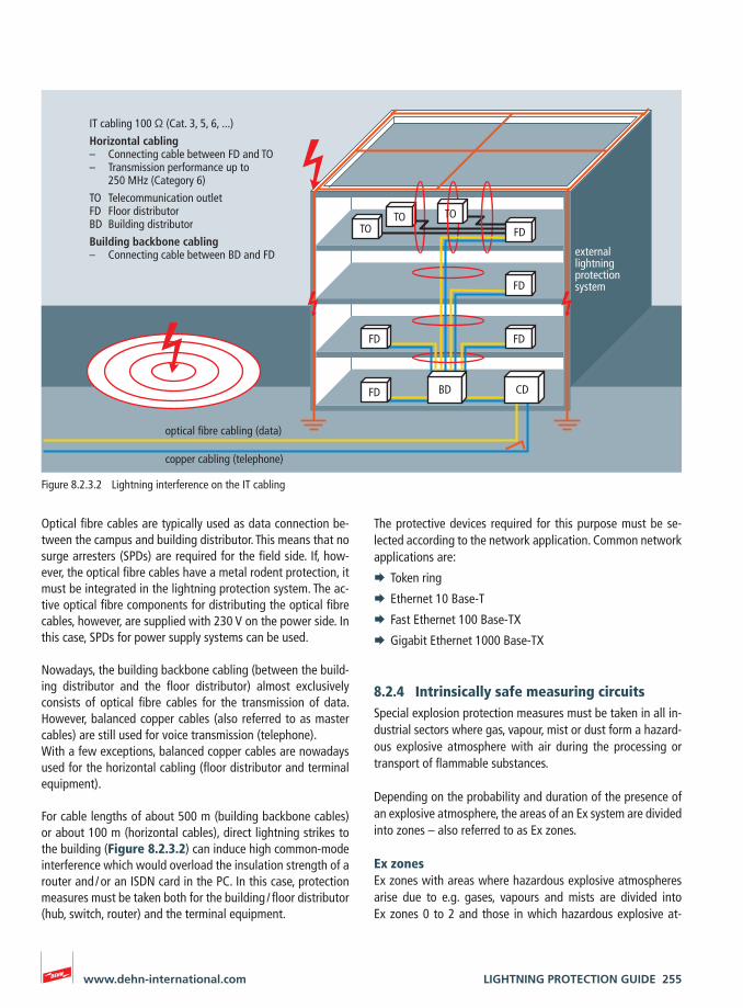
LIGHTNING PROTECTION GUIDE 255www.dehn-international.com
The protective devices required for this purpose must be se-lected according to the network application. Common network applications are:
¨ Token ring
¨ Ethernet 10 Base-T
¨ Fast Ethernet 100 Base-TX
¨ Gigabit Ethernet 1000 Base-TX
8.2.4 Intrinsically safe measuring circuitsSpecial explosion protection measures must be taken in all in-dustrial sectors where gas, vapour, mist or dust form a hazard-ous explosive atmosphere with air during the processing or transport of flammable substances.
Depending on the probability and duration of the presence of an explosive atmosphere, the areas of an Ex system are divided into zones – also referred to as Ex zones.
Ex zonesEx zones with areas where hazardous explosive atmospheres arise due to e.g. gases, vapours and mists are divided into Ex zones 0 to 2 and those in which hazardous explosive at-
Optical fibre cables are typically used as data connection be-tween the campus and building distributor. This means that no surge arresters (SPDs) are required for the field side. If, how-ever, the optical fibre cables have a metal rodent protection, it must be integrated in the lightning protection system. The ac-tive optical fibre components for distributing the optical fibre cables, however, are supplied with 230 V on the power side. In this case, SPDs for power supply systems can be used.
Nowadays, the building backbone cabling (between the build-ing distributor and the floor distributor) almost exclusively consists of optical fibre cables for the transmission of data. However, balanced copper cables (also referred to as master cables) are still used for voice transmission (telephone).With a few exceptions, balanced copper cables are nowadays used for the horizontal cabling (floor distributor and terminal equipment).
For cable lengths of about 500 m (building backbone cables) or about 100 m (horizontal cables), direct lightning strikes to the building (Figure 8.2.3.2) can induce high common-mode interference which would overload the insulation strength of a router and / or an ISDN card in the PC. In this case, protection measures must be taken both for the building / floor distributor (hub, switch, router) and the terminal equipment.
IT cabling 100 Ω (Cat. 3, 5, 6, ...)
Horizontal cabling– Connecting cable between FD and TO – Transmission performance up to 250 MHz (Category 6)
TO Telecommunication outletFD Floor distributorBD Building distributor
Building backbone cabling– Connecting cable between BD and FD
optical fibre cabling (data)
copper cabling (telephone)
TO
FD
FD
TOTO FD
FD
FD
BD CD
external lightning protection system
Figure 8.2.3.2 Lightning interference on the IT cabling
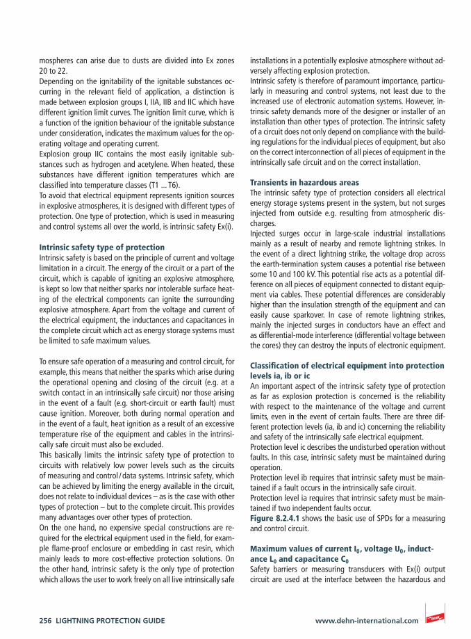
256 LIGHTNING PROTECTION GUIDE www.dehn-international.com
installations in a potentially explosive atmosphere without ad-versely affecting explosion protection.Intrinsic safety is therefore of paramount importance, particu-larly in measuring and control systems, not least due to the increased use of electronic automation systems. However, in-trinsic safety demands more of the designer or installer of an installation than other types of protection. The intrinsic safety of a circuit does not only depend on compliance with the build-ing regulations for the individual pieces of equipment, but also on the correct interconnection of all pieces of equipment in the intrinsically safe circuit and on the correct installation.
Transients in hazardous areasThe intrinsic safety type of protection considers all electrical energy storage systems present in the system, but not surges injected from outside e.g. resulting from atmospheric dis-charges.Injected surges occur in large-scale industrial installations mainly as a result of nearby and remote lightning strikes. In the event of a direct lightning strike, the voltage drop across the earth-termination system causes a potential rise between some 10 and 100 kV. This potential rise acts as a potential dif-ference on all pieces of equipment connected to distant equip-ment via cables. These potential differences are considerably higher than the insulation strength of the equipment and can easily cause sparkover. In case of remote lightning strikes, mainly the injected surges in conductors have an effect and as differential-mode interference (differential voltage between the cores) they can destroy the inputs of electronic equipment.
Classification of electrical equipment into protection levels ia, ib or icAn important aspect of the intrinsic safety type of protection as far as explosion protection is concerned is the reliability with respect to the maintenance of the voltage and current limits, even in the event of certain faults. There are three dif-ferent protection levels (ia, ib and ic) concerning the reliability and safety of the intrinsically safe electrical equipment.Protection level ic describes the undisturbed operation without faults. In this case, intrinsic safety must be maintained during operation.Protection level ib requires that intrinsic safety must be main-tained if a fault occurs in the intrinsically safe circuit.Protection level ia requires that intrinsic safety must be main-tained if two independent faults occur.Figure 8.2.4.1 shows the basic use of SPDs for a measuring and control circuit.
Maximum values of current I0 , voltage U0 , induct-ance L0 and capacitance C0Safety barriers or measuring transducers with Ex(i) output circuit are used at the interface between the hazardous and
mospheres can arise due to dusts are divided into Ex zones 20 to 22.Depending on the ignitability of the ignitable substances oc-curring in the relevant field of application, a distinction is made between explosion groups I, IIA, IIB and IIC which have different ignition limit curves. The ignition limit curve, which is a function of the ignition behaviour of the ignitable substance under consideration, indicates the maximum values for the op-erating voltage and operating current.Explosion group IIC contains the most easily ignitable sub-stances such as hydrogen and acetylene. When heated, these substances have different ignition temperatures which are classified into temperature classes (T1 ... T6).To avoid that electrical equipment represents ignition sources in explosive atmospheres, it is designed with different types of protection. One type of protection, which is used in measuring and control systems all over the world, is intrinsic safety Ex(i).
Intrinsic safety type of protectionIntrinsic safety is based on the principle of current and voltage limitation in a circuit. The energy of the circuit or a part of the circuit, which is capable of igniting an explosive atmosphere, is kept so low that neither sparks nor intolerable surface heat-ing of the electrical components can ignite the surrounding explosive atmosphere. Apart from the voltage and current of the electrical equipment, the inductances and capacitances in the complete circuit which act as energy storage systems must be limited to safe maximum values.
To ensure safe operation of a measuring and control circuit, for example, this means that neither the sparks which arise during the operational opening and closing of the circuit (e.g. at a switch contact in an intrinsically safe circuit) nor those arising in the event of a fault (e.g. short-circuit or earth fault) must cause ignition. Moreover, both during normal operation and in the event of a fault, heat ignition as a result of an excessive temperature rise of the equipment and cables in the intrinsi-cally safe circuit must also be excluded.This basically limits the intrinsic safety type of protection to circuits with relatively low power levels such as the circuits of measuring and control / data systems. Intrinsic safety, which can be achieved by limiting the energy available in the circuit, does not relate to individual devices – as is the case with other types of protection – but to the complete circuit. This provides many advantages over other types of protection. On the one hand, no expensive special constructions are re-quired for the electrical equipment used in the field, for exam-ple flame-proof enclosure or embedding in cast resin, which mainly leads to more cost-effective protection solutions. On the other hand, intrinsic safety is the only type of protection which allows the user to work freely on all live intrinsically safe
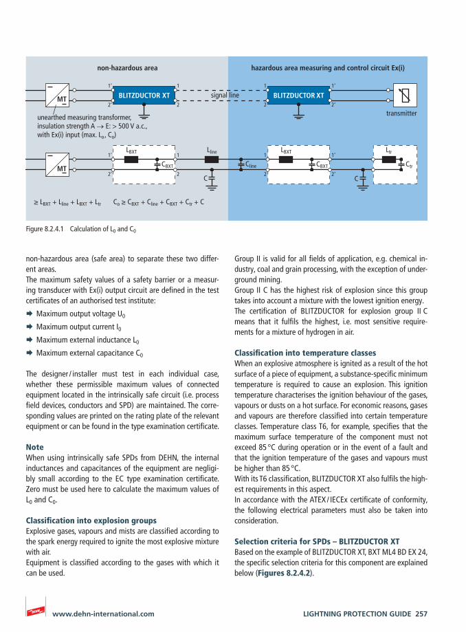
LIGHTNING PROTECTION GUIDE 257www.dehn-international.com
Group II is valid for all fields of application, e.g. chemical in-dustry, coal and grain processing, with the exception of under-ground mining.Group II C has the highest risk of explosion since this group takes into account a mixture with the lowest ignition energy.The certification of BLITZDUCTOR for explosion group II C means that it fulfils the highest, i.e. most sensitive require-ments for a mixture of hydrogen in air.
Classification into temperature classesWhen an explosive atmosphere is ignited as a result of the hot surface of a piece of equipment, a substance-specific minimum temperature is required to cause an explosion. This ignition temperature characterises the ignition behaviour of the gases, vapours or dusts on a hot surface. For economic reasons, gases and vapours are therefore classified into certain temperature classes. Temperature class T6, for example, specifies that the maximum surface temperature of the component must not exceed 85 °C during operation or in the event of a fault and that the ignition temperature of the gases and vapours must be higher than 85 °C.With its T6 classification, BLITZDUCTOR XT also fulfils the high-est requirements in this aspect.In accordance with the ATEX / IECEx certificate of conformity, the following electrical parameters must also be taken into consideration.
Selection criteria for SPDs – BLITZDUCTOR XTBased on the example of BLITZDUCTOR XT, BXT ML4 BD EX 24, the specific selection criteria for this component are explained below (Figures 8.2.4.2).
non-hazardous area (safe area) to separate these two differ-ent areas.The maximum safety values of a safety barrier or a measur-ing transducer with Ex(i) output circuit are defined in the test certificates of an authorised test institute:
¨ Maximum output voltage U0
¨ Maximum output current I0 ¨ Maximum external inductance L0
¨ Maximum external capacitance C0
The designer / installer must test in each individual case, whether these permissible maximum values of connected equipment located in the intrinsically safe circuit (i.e. process field devices, conductors and SPD) are maintained. The corre-sponding values are printed on the rating plate of the relevant equipment or can be found in the type examination certificate.
NoteWhen using intrinsically safe SPDs from DEHN, the internal inductances and capacitances of the equipment are negligi-bly small according to the EC type examination certificate. Zero must be used here to calculate the maximum values of L0 and C0.
Classification into explosion groupsExplosive gases, vapours and mists are classified according to the spark energy required to ignite the most explosive mixture with air.Equipment is classified according to the gases with which it can be used.
1’ 1
2’ 2
1 1‘
2 2‘
1’ 1
2’ 2
1 1‘
2 2‘
BLITZDUCTOR XT BLITZDUCTOR XT
LBXT
CBXT
C
LBXT
CBXT
C
unearthed measuring transformer, insulation strength A → E: > 500 V a.c., with Ex(i) input (max. Lo , Co)
MT
MT
transmitter
Lline
Cline
Ltr
Ctr
non-hazardous area hazardous area measuring and control circuit Ex(i)
≥ LBXT + Lline + LBXT + Ltr Co ≥ CBXT + Cline + CBXT + Ctr + C
signal line
Figure 8.2.4.1 Calculation of L0 and C0
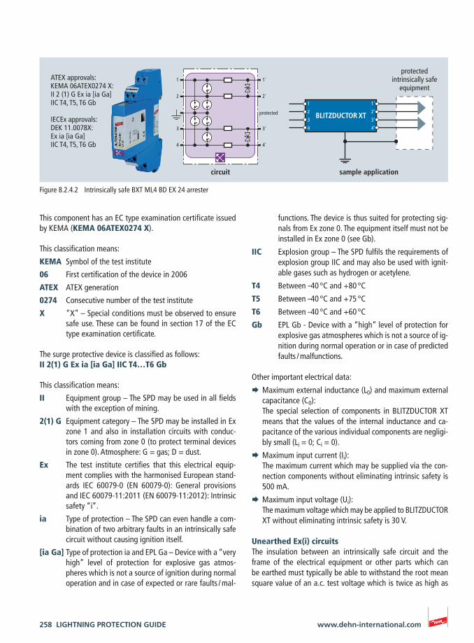
258 LIGHTNING PROTECTION GUIDE www.dehn-international.com
functions. The device is thus suited for protecting sig-nals from Ex zone 0. The equipment itself must not be installed in Ex zone 0 (see Gb).
IIC Explosion group – The SPD fulfils the requirements of explosion group IIC and may also be used with ignit-able gases such as hydrogen or acetylene.
T4 Between –40 °C and +80 °C
T5 Between –40 °C and +75 °C
T6 Between –40 °C and +60 °C
Gb EPL Gb - Device with a “high” level of protection for explosive gas atmospheres which is not a source of ig-nition during normal operation or in case of predicted faults / malfunctions.
Other important electrical data:
¨ Maximum external inductance (L0) and maximum external capacitance (C0):
The special selection of components in BLITZDUCTOR XT means that the values of the internal inductance and ca-pacitance of the various individual components are negligi-bly small (Li = 0; Ci = 0).
¨ Maximum input current (Ii): The maximum current which may be supplied via the con-
nection components without eliminating intrinsic safety is 500 mA.
¨ Maximum input voltage (Ui): The maximum voltage which may be applied to BLITZ DUCTOR
XT without eliminating intrinsic safety is 30 V.
Unearthed Ex(i) circuitsThe insulation between an intrinsically safe circuit and the frame of the electrical equipment or other parts which can be earthed must typically be able to withstand the root mean square value of an a.c. test voltage which is twice as high as
This component has an EC type examination certificate issued by KEMA (KEMA 06ATEX0274 X).
This classification means:
KEMA Symbol of the test institute
06 First certification of the device in 2006
ATEX ATEX generation
0274 Consecutive number of the test institute
X “X” – Special conditions must be observed to ensure safe use. These can be found in section 17 of the EC type examination certificate.
The surge protective device is classified as follows:II 2(1) G Ex ia [ia Ga] IIC T4…T6 Gb
This classification means:
II Equipment group – The SPD may be used in all fields with the exception of mining.
2(1) G Equipment category – The SPD may be installed in Ex zone 1 and also in installation circuits with conduc-tors coming from zone 0 (to protect terminal devices in zone 0). Atmosphere: G = gas; D = dust.
Ex The test institute certifies that this electrical equip-ment complies with the harmonised European stand-ards IEC 60079-0 (EN 60079-0): General provisions and IEC 60079-11:2011 (EN 60079-11:2012): Intrinsic safety “i”.
ia Type of protection – The SPD can even handle a com-bination of two arbitrary faults in an intrinsically safe circuit without causing ignition itself.
[ia Ga] Type of protection ia and EPL Ga – Device with a “very high” level of protection for explosive gas atmos-pheres which is not a source of ignition during normal operation and in case of expected or rare faults / mal-
1
2
3
4
1’
2’
3’
4’
BLITZDUCTOR XT
1
2
1´
2´
3 3´
4 4´
protected
ATEX approvals:KEMA 06ATEX0274 X:II 2 (1) G Ex ia [ia Ga] IIC T4, T5, T6 Gb
IECEx approvals:DEK 11.0078X:Ex ia [ia Ga]IIC T4, T5, T6 Gb
circuit sample application
protected intrinsically safe
equipment
Figure 8.2.4.2 Intrinsically safe BXT ML4 BD EX 24 arrester
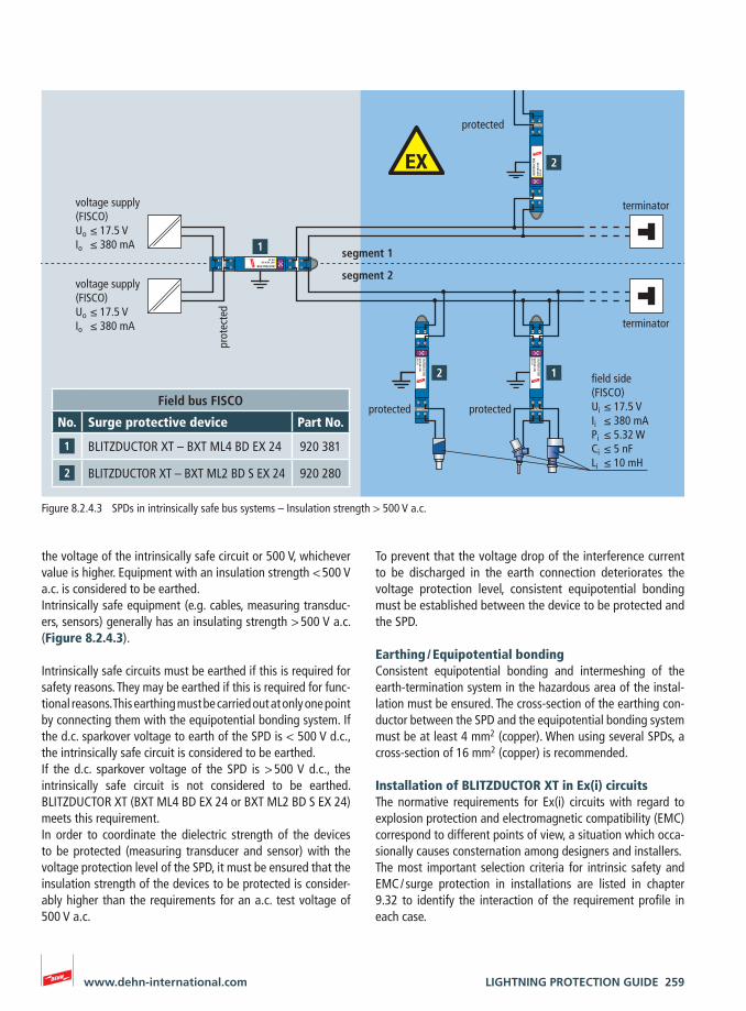
LIGHTNING PROTECTION GUIDE 259www.dehn-international.com
To prevent that the voltage drop of the interference current to be discharged in the earth connection deteriorates the voltage protection level, consistent equipotential bonding must be established between the device to be protected and the SPD.
Earthing / Equipotential bondingConsistent equipotential bonding and intermeshing of the earth-termination system in the hazardous area of the instal-lation must be ensured. The cross-section of the earthing con-ductor between the SPD and the equipotential bonding system must be at least 4 mm2 (copper). When using several SPDs, a cross-section of 16 mm2 (copper) is recommended.
Installation of BLITZDUCTOR XT in Ex(i) circuitsThe normative requirements for Ex(i) circuits with regard to explosion protection and electromagnetic compatibility (EMC) correspond to different points of view, a situation which occa-sionally causes consternation among designers and installers.The most important selection criteria for intrinsic safety and EMC / surge protection in installations are listed in chapter 9.32 to identify the interaction of the requirement profile in each case.
the voltage of the intrinsically safe circuit or 500 V, whichever value is higher. Equipment with an insulation strength < 500 V a.c. is considered to be earthed. Intrinsically safe equipment (e.g. cables, measuring transduc-ers, sensors) generally has an insulating strength > 500 V a.c. (Figure 8.2.4.3).
Intrinsically safe circuits must be earthed if this is required for safety reasons. They may be earthed if this is required for func-tional reasons. This earthing must be carried out at only one point by connecting them with the equipotential bonding system. If the d.c. sparkover voltage to earth of the SPD is < 500 V d.c., the intrinsically safe circuit is considered to be earthed.If the d.c. sparkover voltage of the SPD is > 500 V d.c., the intrinsically safe circuit is not considered to be earthed. BLITZDUCTOR XT (BXT ML4 BD EX 24 or BXT ML2 BD S EX 24) meets this requirement.In order to coordinate the dielectric strength of the devices to be protected (measuring transducer and sensor) with the voltage protection level of the SPD, it must be ensured that the insulation strength of the devices to be protected is consider-ably higher than the requirements for an a.c. test voltage of 500 V a.c.
BXT
ML4
BD
EX
24
BLIT
ZDU
CTO
R
2’ 4’
1’ 3’
2 4
1 3
protected
BXT ML4 BD EX 24
BLITZDUCTOR
2’4’
1’3’
24
13
prot
ecte
d
BXT ML4 BD
EX 24
BLITZDU
CTOR
2’4’
1’3’
24
13
protected
BXT ML4 BD
EX 24
BLITZDU
CTOR
2’4’
1’3’
24
13
protected
protected
protected protected
prot
ecte
d
field side (FISCO)Ui ≤ 17.5 VIi ≤ 380 mAPi ≤ 5.32 WCi ≤ 5 nFLi ≤ 10 mH
voltage supply (FISCO) Uo ≤ 17.5 VIo ≤ 380 mA
voltage supply (FISCO) Uo ≤ 17.5 VIo ≤ 380 mA
segment 1
segment 2
terminator
terminator
Figure 8.2.4.3 SPDs in intrinsically safe bus systems – Insulation strength > 500 V a.c.
Field bus FISCO
No. Surge protective device Part No.
BLITZDUCTOR XT – BXT ML4 BD EX 24 920 381
BLITZDUCTOR XT – BXT ML2 BD S EX 24 920 280
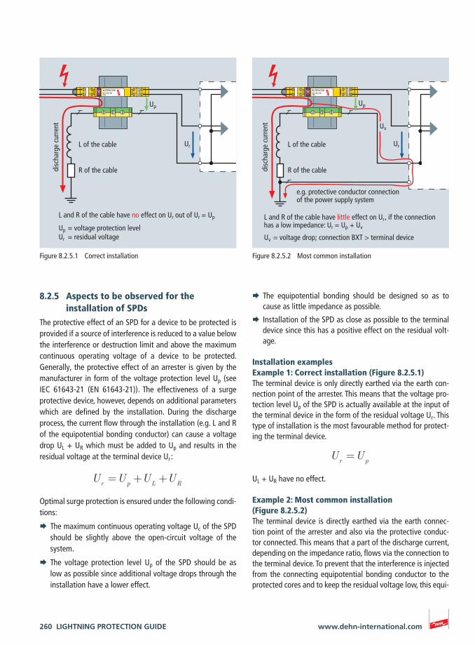
260 LIGHTNING PROTECTION GUIDE www.dehn-international.com
8.2.5 Aspects to be observed for the installation of SPDs
The protective effect of an SPD for a device to be protected is provided if a source of interference is reduced to a value below the interference or destruction limit and above the maximum continuous operating voltage of a device to be protected. Generally, the protective effect of an arrester is given by the manufacturer in form of the voltage protection level Up (see IEC 61643-21 (EN 61643-21)). The effectiveness of a surge protective device, however, depends on additional parameters which are defined by the installation. During the discharge process, the current flow through the installation (e.g. L and R of the equipotential bonding conductor) can cause a voltage drop UL + UR which must be added to Up and results in the residual voltage at the terminal device Ur :
Ur=U
p+U
L+U
R
Optimal surge protection is ensured under the following condi-tions:
¨ The maximum continuous operating voltage Uc of the SPD should be slightly above the open-circuit voltage of the system.
¨ The voltage protection level Up of the SPD should be as low as possible since additional voltage drops through the installation have a lower effect.
¨ The equipotential bonding should be designed so as to cause as little impedance as possible.
¨ Installation of the SPD as close as possible to the terminal device since this has a positive effect on the residual volt-age.
Installation examplesExample 1: Correct installation (Figure 8.2.5.1)The terminal device is only directly earthed via the earth con-nection point of the arrester. This means that the voltage pro-tection level Up of the SPD is actually available at the input of the terminal device in the form of the residual voltage Ur . This type of installation is the most favourable method for protect-ing the terminal device.
Ur=U
p
UL + UR have no effect.
Example 2: Most common installation (Figure 8.2.5.2)The terminal device is directly earthed via the earth connec-tion point of the arrester and also via the protective conduc-tor connected. This means that a part of the discharge current, depending on the impedance ratio, flows via the connection to the terminal device. To prevent that the interference is injected from the connecting equipotential bonding conductor to the protected cores and to keep the residual voltage low, this equi-
BXT ML2 BD 180
BLITZDUCTOR
2’4’
1’3’
24
13
protected
disc
harg
e cu
rren
t
L of the cable
R of the cable
L and R of the cable have no effect on Ur out of Ur = Up
Up = voltage protection levelUr = residual voltage
Up
Ur
Figure 8.2.5.1 Correct installation
BXT ML2 BD 180
BLITZDUCTOR
2’4’
1’3’
24
13
protected
L and R of the cable have little effect on Ur , if the connection has a low impedance: Ur = Up + Uv
e.g. protective conductor connection of the power supply system
Uv = voltage drop; connection BXT > terminal device
Up
Uv
Ur
disc
harg
e cu
rren
t
L of the cable
R of the cable
Figure 8.2.5.2 Most common installation
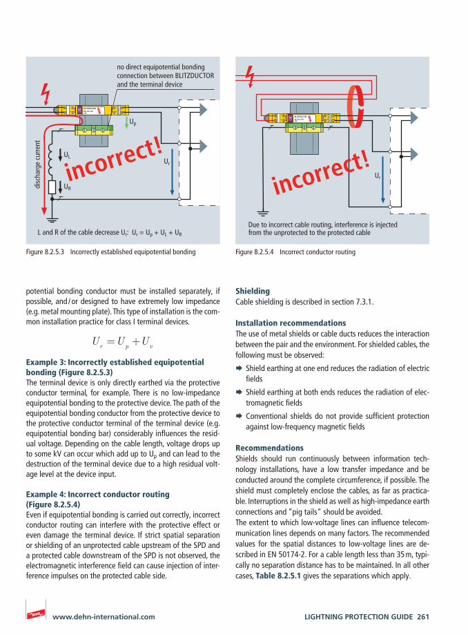
LIGHTNING PROTECTION GUIDE 261www.dehn-international.com
potential bonding conductor must be installed separately, if possible, and / or designed to have extremely low impedance (e.g. metal mounting plate). This type of installation is the com-mon installation practice for class I terminal devices.
Ur=U
p+U
v
Example 3: Incorrectly established equipotential bonding (Figure 8.2.5.3)The terminal device is only directly earthed via the protective conductor terminal, for example. There is no low-impedance equipotential bonding to the protective device. The path of the equipotential bonding conductor from the protective device to the protective conductor terminal of the terminal device (e.g. equipotential bonding bar) considerably influences the resid-ual voltage. Depending on the cable length, voltage drops up to some kV can occur which add up to Up and can lead to the destruction of the terminal device due to a high residual volt-age level at the device input.
Example 4: Incorrect conductor routing (Figure 8.2.5.4)Even if equipotential bonding is carried out correctly, incorrect conductor routing can interfere with the protective effect or even damage the terminal device. If strict spatial separation or shielding of an unprotected cable upstream of the SPD and a protected cable downstream of the SPD is not observed, the electromagnetic interference field can cause injection of inter-ference impulses on the protected cable side.
ShieldingCable shielding is described in section 7.3.1.
Installation recommendations The use of metal shields or cable ducts reduces the interaction between the pair and the environment. For shielded cables, the following must be observed:
¨ Shield earthing at one end reduces the radiation of electric fields
¨ Shield earthing at both ends reduces the radiation of elec-tromagnetic fields
¨ Conventional shields do not provide sufficient protection against low-frequency magnetic fields
RecommendationsShields should run continuously between information tech-nology installations, have a low transfer impedance and be conducted around the complete circumference, if possible. The shield must completely enclose the cables, as far as practica-ble. Interruptions in the shield as well as high-impedance earth connections and “pig tails“ should be avoided.The extent to which low-voltage lines can influence telecom-munication lines depends on many factors. The recommended values for the spatial distances to low-voltage lines are de-scribed in EN 50174-2. For a cable length less than 35 m, typi-cally no separation distance has to be maintained. In all other cases, Table 8.2.5.1 gives the separations which apply.
BXT ML2 BD 180
BLITZDUCTOR
2’4’
1’3’
24
13
protected
no direct equipotential bonding connection between BLITZDUCTOR and the terminal device
L and R of the cable decrease Ur: Ur = Up + UL + UR
Up
Ur
disc
harg
e cu
rren
t
UL
UR
incorrect!
Figure 8.2.5.3 Incorrectly established equipotential bonding
BXT ML2 BD 180
BLITZDUCTOR
2’4’
1’3’
24
13
protected
Due to incorrect cable routing, interference is injected from the unprotected to the protected cable
Ur
incorrect!
Figure 8.2.5.4 Incorrect conductor routing
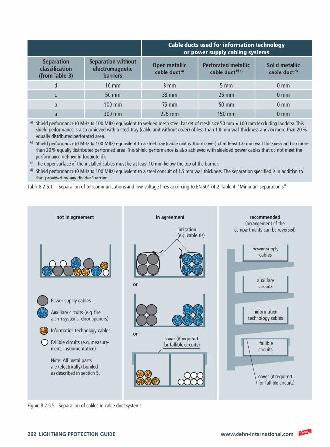
262 LIGHTNING PROTECTION GUIDE www.dehn-international.com
Table 8.2.5.1 Separation of telecommunications and low-voltage lines according to EN 50174-2, Table 4: “Minimum separation s”
not in agreement in agreement recommended (arrangement of the
compartments can be reversed)limitation (e.g. cable tie)
cover (if required for fallible circuits)
cover (if required for fallible circuits)
or
or
Power supply cables
Auxiliary circuits (e.g. fire alarm systems, door openers)
Information technology cables
Fallible circuits (e.g. measure-ment, instrumentation)
Note: All metal parts are (electrically) bonded as described in section 5.
fallible circuits
information technology cables
auxiliarycircuits
power supply cables
Figure 8.2.5.5 Separation of cables in cable duct systems
Cable ducts used for information technology or power supply cabling systems
Separation classification (from Table 3)
Separation without electromagnetic
barriers
Open metallic cable duct a)
Perforated metallic cable duct b) c)
Solid metallic cable duct d)
d 10 mm 8 mm 5 mm 0 mm
c 50 mm 38 mm 25 mm 0 mm
b 100 mm 75 mm 50 mm 0 mm
a 300 mm 225 mm 150 mm 0 mma) Shield performance (0 MHz to 100 MHz) equivalent to welded mesh steel basket of mesh size 50 mm × 100 mm (excluding ladders). This
shield performance is also achieved with a steel tray (cable unit without cover) of less than 1.0 mm wall thickness and / or more than 20 % equally distributed perforated area.
b) Shield performance (0 MHz to 100 MHz) equivalent to a steel tray (cable unit without cover) of at least 1.0 mm wall thickness and no more than 20 % equally distributed perforated area. This shield performance is also achieved with shielded power cables that do not meet the performance defined in footnote d).
c) The upper surface of the installed cables must be at least 10 mm below the top of the barrier.d) Shield performance (0 MHz to 100 MHz) equivalent to a steel conduit of 1.5 mm wall thickness. The separation specified is in addition to
that provided by any divider / barrier.
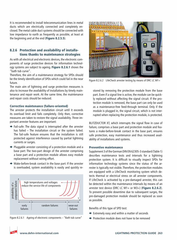
LIGHTNING PROTECTION GUIDE 263www.dehn-international.com
It is recommended to install telecommunication lines in metal ducts which are electrically connected and completely en-closed. The metal cable duct systems should be connected with low impedance to earth as frequently as possible, at least at the beginning and at the end (Figure 8.2.5.5).
8.2.6 Protection and availability of installa-tions thanks to maintenance strategies
As with all electrical and electronic devices, the electronic com-ponents of surge protective devices for information technol-ogy systems are subject to ageing. Figure 8.2.6.1 shows the “bath tub curve”.Therefore, the aim of a maintenance strategy for SPDs should be the timely identification of SPDs which could fail in the near future.The main aim of lightning and surge protection measures is also to increase the availability of installations by timely main-tenance and repair work. At the same time, the maintenance and repair costs should be reduced.
Corrective maintenance (failure-oriented)The arrester protects the installation circuit until it exceeds its overload limit and fails completely. Only then, corrective measures are taken to restore the signal availability. Three im-portant arrester features are important:
¨ Fail-safe: The data signal is interrupted after the arrester has failed – The installation circuit or the system failed. The fail-safe feature ensures that the installation is still protected against interference caused by partial lightning currents or surges.
¨ Pluggable arrester consisting of a protection module and a base part: The two-part design of the arrester comprising a base part and a protection module allows easy module replacement without wiring effort.
¨ Make-before-break contact in the base part: If the arrester is overloaded, system availability is easily and quickly re-
stored by removing the protection module from the base part. Even if a signal line is active, the module can be quick-ly replaced without affecting the signal circuit. If the pro-tection module is removed, the base part can only be used as a maintenance-free feed-through terminal. Only if the module is plugged in, the signal circuit, which is not inter-rupted when replacing the protection module, is protected.
BLITZDUCTOR XT, which interrupts the signal flow in case of failure, comprises a base part and protection module and fea-tures a make-before-break contact in the base part, ensures safe protection, easy maintenance and thus increased avail-ability of installations and systems.
Preventive maintenanceSupplement 3 of the German DIN EN 62305-3 standard (Table 1) describes maintenance tests and intervals for a lightning protection system. It is difficult to visually inspect SPDs for information technology systems since the status of the ar-rester is typically not visible. Therefore, the protection modules are equipped with a LifeCheck monitoring system which de-tects thermal or electrical stress on all arrester components. If LifeCheck is activated by a pre-damaged arrester, this can be detected within the maintenance intervals by means of an arrester test device (DRC LC M1+ or M3+) (Figure 8.2.6.2). To prevent possible downtime due to subsequent surges, the pre-damaged protection module should be replaced as soon as possible.
Benefits of this type of SPD test:
¨ Extremely easy and within a matter of seconds
¨ Protection module does not have to be removed
t
random failures
high temperatures and voltages reduce the service life of components
prob
abili
ty o
f a
com
pone
nt fa
ilure
earlyfailures
wear-out failures
Figure 8.2.6.1 Ageing of electronic components – “Bath tub curve”
Figure 8.2.6.2 LifeCheck arrester testing by means of DRC LC M1+
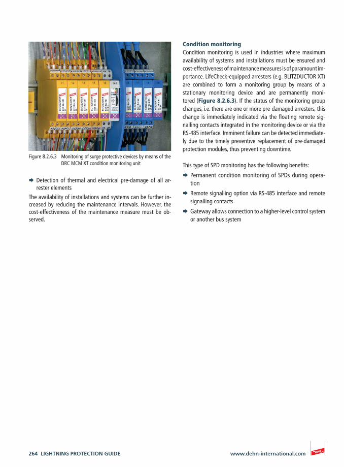
264 LIGHTNING PROTECTION GUIDE www.dehn-international.com
¨ Detection of thermal and electrical pre-damage of all ar-rester elements
The availability of installations and systems can be further in-creased by reducing the maintenance intervals. However, the cost-effectiveness of the maintenance measure must be ob-served.
Condition monitoringCondition monitoring is used in industries where maximum availability of systems and installations must be ensured and cost-effectiveness of maintenance measures is of paramount im-portance. LifeCheck-equipped arresters (e.g. BLITZDUCTOR XT) are combined to form a monitoring group by means of a stationary monitoring device and are permanently moni-tored (Figure 8.2.6.3). If the status of the monitoring group changes, i.e. there are one or more pre-damaged arresters, this change is immediately indicated via the floating remote sig-nalling contacts integrated in the monitoring device or via the RS-485 interface. Imminent failure can be detected immediate-ly due to the timely preventive replacement of pre-damaged protection modules, thus preventing downtime.
This type of SPD monitoring has the following benefits:
¨ Permanent condition monitoring of SPDs during opera-tion
¨ Remote signalling option via RS-485 interface and remote signalling contacts
¨ Gateway allows connection to a higher-level control system or another bus system
Figure 8.2.6.3 Monitoring of surge protective devices by means of the DRC MCM XT condition monitoring unit

LIGHTNING PROTECTION GUIDE 265www.dehn-international.com


![Assembly [Ελληνικο Μαθημα]](https://static.fdocument.org/doc/165x107/55cf96d2550346d0338e019c/assembly-.jpg)