
SDA Procedure for Membrane Tank LNG Ships - Class Direct · PDF fileSDA Procedure for Membrane...
71
ShipRight Design and Construction Structural Design Assessment Procedure for Membrane Tank LNG Ships September 2016 Working together for a safer world
Transcript of SDA Procedure for Membrane Tank LNG Ships - Class Direct · PDF fileSDA Procedure for Membrane...
ShipRight Design and Construction
Structural Design Assessment
Procedure for Membrane Tank LNG Ships
September 2016
Working together
for a safer world
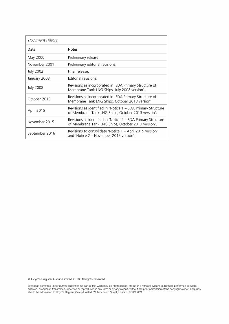
Document History
Date:
Notes:
May 2000 Preliminary release.
November 2001 Preliminary editorial revisions.
July 2002 Final release.
January 2003 Editorial revisions.
July 2008 Revisions as incorporated in ‘SDA Primary Structure of Membrane Tank LNG Ships, July 2008 version’.
October 2013 Revisions as incorporated in ‘SDA Primary Structure of Membrane Tank LNG Ships, October 2013 version’.
April 2015 Revisions as identified in ‘Notice 1 – SDA Primary Structure of Membrane Tank LNG Ships, October 2013 version’.
November 2015 Revisions as identified in ‘Notice 2 – SDA Primary Structure of Membrane Tank LNG Ships, October 2013 version’.
September 2016 Revisions to consolidate ‘Notice 1 – April 2015 version’ and ‘Notice 2 – November 2015 version’.
© Lloyd's Register Group Limited 2016. All rights reserved. Except as permitted under current legislation no part of this work may be photocopied, stored in a retrieval system, published, performed in public, adapted, broadcast, transmitted, recorded or reproduced in any form or by any means, without the prior permission of the copyright owner. Enquiries should be addressed to Lloyd's Register Group Limited, 71 Fenchurch Street, London, EC3M 4BS.
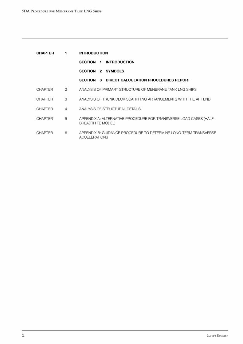
CHAPTER 1 INTRODUCTION
SECTION 1 INTRODUCTION
SECTION 2 SYMBOLS
SECTION 3 DIRECT CALCULATION PROCEDURES REPORT
CHAPTER 2 ANALYSIS OF PRIMARY STRUCTURE OF MENBRANE TANK LNG SHIPS
CHAPTER 3 ANALYSIS OF TRUNK DECK SCARPHING ARRANGEMENTS WITH THE AFT END
CHAPTER 4 ANALYSIS OF STRUCTURAL DETAILS
CHAPTER 5 APPENDIX A: ALTERNATIVE PROCEDURE FOR TRANSVERSE LOAD CASES (HALF-BREADTH FE MODEL)
CHAPTER 6 APPENDIX B: GUIDANCE PROCEDURE TO DETERMINE LONG-TERM TRANSVERSEACCELERATIONS
SDA Procedure for Membrane Tank LNG Ships
2 Lloyd's Register
Section1 Introduction
2 Symbols
3 Direct calculation procedures report
n Section 1 Introduction
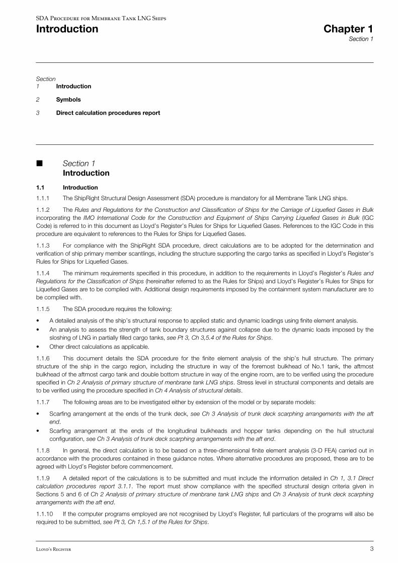
1.1 Introduction
1.1.1 The ShipRight Structural Design Assessment (SDA) procedure is mandatory for all Membrane Tank LNG ships.
1.1.2 The Rules and Regulations for the Construction and Classification of Ships for the Carriage of Liquefied Gases in Bulkincorporating the IMO International Code for the Construction and Equipment of Ships Carrying Liquefied Gases in Bulk (IGCCode) is referred to in this document as Lloyd’s Register’s Rules for Ships for Liquefied Gases. References to the IGC Code in thisprocedure are equivalent to references to the Rules for Ships for Liquefied Gases.
1.1.3 For compliance with the ShipRight SDA procedure, direct calculations are to be adopted for the determination andverification of ship primary member scantlings, including the structure supporting the cargo tanks as specified in Lloyd’s Register’sRules for Ships for Liquefied Gases.
1.1.4 The minimum requirements specified in this procedure, in addition to the requirements in Lloyd’s Register’s Rules andRegulations for the Classification of Ships (hereinafter referred to as the Rules for Ships) and Lloyd’s Register’s Rules for Ships forLiquefied Gases are to be complied with. Additional design requirements imposed by the containment system manufacturer are tobe complied with.
1.1.5 The SDA procedure requires the following:
• A detailed analysis of the ship’s structural response to applied static and dynamic loadings using finite element analysis.
• An analysis to assess the strength of tank boundary structures against collapse due to the dynamic loads imposed by thesloshing of LNG in partially filled cargo tanks, see Pt 3, Ch 3,5.4 of the Rules for Ships.
• Other direct calculations as applicable.
1.1.6 This document details the SDA procedure for the finite element analysis of the ship’s hull structure. The primarystructure of the ship in the cargo region, including the structure in way of the foremost bulkhead of No.1 tank, the aftmostbulkhead of the aftmost cargo tank and double bottom structure in way of the engine room, are to be verified using the procedurespecified in Ch 2 Analysis of primary structure of menbrane tank LNG ships. Stress level in structural components and details areto be verified using the procedure specified in Ch 4 Analysis of structural details.
1.1.7 The following areas are to be investigated either by extension of the model or by separate models:
• Scarfing arrangement at the ends of the trunk deck, see Ch 3 Analysis of trunk deck scarphing arrangements with the aftend.
• Scarfing arrangement at the ends of the longitudinal bulkheads and hopper tanks depending on the hull structuralconfiguration, see Ch 3 Analysis of trunk deck scarphing arrangements with the aft end.
1.1.8 In general, the direct calculation is to be based on a three-dimensional finite element analysis (3-D FEA) carried out inaccordance with the procedures contained in these guidance notes. Where alternative procedures are proposed, these are to beagreed with Lloyd’s Register before commencement.
1.1.9 A detailed report of the calculations is to be submitted and must include the information detailed in Ch 1, 3.1 Directcalculation procedures report 3.1.1. The report must show compliance with the specified structural design criteria given inSections 5 and 6 of Ch 2 Analysis of primary structure of menbrane tank LNG ships and Ch 3 Analysis of trunk deck scarphingarrangements with the aft end.
1.1.10 If the computer programs employed are not recognised by Lloyd’s Register, full particulars of the programs will also berequired to be submitted, see Pt 3, Ch 1,5.1 of the Rules for Ships.
SDA Procedure for Membrane Tank LNG Ships
Introduction Chapter 1Section 1
Lloyd's Register 3
1.1.11 Lloyd’s Register may require the submission of computer input and output to verify further the adequacy of thecalculations carried out.
1.1.12 Ships which have novel features or unusual hull structural or tank configurations may need special consideration.
1.1.13 It is recommended that the designer consult with Lloyd’s Register on the SDA analysis requirements early on in thedesign cycle.
IMPORTANT NOTE
The objective of this procedure is to assess the strength of the ship primary structure to withstand the design loads. The ability ofthe containment system to accommodate the global or local deformations of the ship structure is not considered in this procedure.Therefore, it is necessary for the designers to consider and demonstrate separately that the containment system design in terms ofstrength and fatigue capability can withstand the global and local deformations of the ship structure. Additional designrequirements with respect to the ship structure specified by the containment system supplier are to be complied with. It isrecommended that the designer consult the containment system supplier early on in the design cycle.
n Section 2 Symbols
2.1 Symbols
2.1.1 The symbols used in these guidance notes are defined as follows:
L = Rule length, as defined in Pt 3, Ch 1,6 of the Rules for Ships
B = moulded breadth, as defined in Pt 3, Ch 1,6 of the Rules for Ships
D = depth of ship, as defined in Pt 3, Ch 1,6 of the Rules for Ships
kL, k = higher tensile steel factor, see Pt 3, Ch 2,1.2 of the Rules for Ships
SWBM = still water bending moment
VWBM = design vertical bending moment
MW = design vertical bending moment, including hog and sag factor, f2, and ship service factor, f1 see Pt 3, Ch4,5 of the Rules for Ships
MWO = vertical wave bending moment, excluding hog and sag factor and ship service factor, see Pt 3, Ch 4,5 ofthe Rules for Ships
f1 = the ship service factor, see Pt 3, Ch 4,5 of the Rules for Ships
f2 = the hogging/sagging factor, see Pt 3, Ch 4,5 of the Rules for Ships�S = Rule permissible still water bending moment, see Pt 3, Ch 4,5 of the Rules for Ships
MS = design still water bending moment, see Pt 3, Ch 4,5 of the Rules for Ships
MSW = still water bending moment distribution envelope to be applied to the FE models for stress and bucklingassessments. The values of MSW are to be greater than MS but not to be less than 0,25 �S. These
values are to be incorporated into the ship’s Loading Manual and loading instrument as the assignedpermissible still water bending moment values. MSW hereinafter referred to as the permissible still waterbending moment. See also Ch 2, 4.1 Introduction 4.1.5
TSC = scantling draught
T = condition draught
θ = heel angle
V = service speed (knots)
g = acceleration due to gravity
SDA Procedure for Membrane Tank LNG Ships
Introduction Chapter 1Section 2
4 Lloyd's Register
ρ = density of sea-water (specific gravity to be taken as 1,025)
h = local head for pressure evaluation
ρc = maximum cargo density at the design temperature, S.G. is not to be taken as less than 0,5
Po = design vapour pressure, see Ch 4, Cargo Containment 4.1.2 of the Rules for Ships for Liquefied Gases
Ax, Ay, Az = maximum dimensionless acceleration factors (i.e., relative to the acceleration of gravity) in thelongitudinal, transverse and vertical directions respectively
hx, hy, hz = local head for pressure evaluation measured from the tank reference point in the longitudinal, transverseand vertical directions respectively
t = thickness of plating
tc = thickness deduction for corrosion
σc = elastic critical buckling stress
σo = specified minimum yield stress of material (special consideration will be given to steel where σo ≥ 355N/mm2, see Pt 3, Ch 2,1 of the Rules for Ships)
σL = 235�� N/mm2
KL = as defined in Pt 3, Ch 3, 2.4 of the Rules for Ships
λ = factor against buckling
τ = shear stress
σe = von Mises equivalent stress given by
σe = σx2+ σy2− σxσy + 3τxy2where
σx = direct stress in element x direction
σy = direct stress in element y direction
τxy = shear stress in element x-y plane.
2.1.2 Consistent units are to be used throughout all parts of the analysis. Results presentation in Newtons and mm preferred.
2.1.3 All Rule equations are to use units as defined in the Rules for Ships.
n Section 3 Direct calculation procedures report
3.1 Direct calculation procedures report
3.1.1 A report is to be submitted to Lloyd’s Register for approval of the primary structure of the ship and is to contain:
• list of plans used, including dates and versions;
• detailed description of structural model, including all modelling assumptions;
• plots to demonstrate correct structural modelling and assigned properties;
• details of material properties used;
• details of displacement boundary conditions;
• details of all still water and dynamic loading conditions reviewed with calculated shear force (SF) and bending moment (BM)distributions;
• details of the calculations for the waterlines used for the dynamic loading conditions;
• details of the acceleration factors for each loading condition;
SDA Procedure for Membrane Tank LNG Ships
Introduction Chapter 1Section 3
Lloyd's Register 5

• details of applied loadings and confirmation that individual and total applied loads are correct;
• details of boundary support forces and moments;
• plots and results that demonstrate the correct behaviour of the structural model to the applied loads;
• summaries and plots of global and local deflections;
• summaries and sufficient plots of von Mises, directional and shear stresses to demonstrate that the design criteria are notexceeded in any member;
• plate buckling analysis and results;
• tabulated results showing compliance, or otherwise, with the design criteria; and
• proposed amendments to structure where necessary, including revised assessment of stresses and buckling properties.
SDA Procedure for Membrane Tank LNG Ships
Introduction Chapter 1Section 3
6 Lloyd's Register
CHAPTER 1 INTRODUCTION
CHAPTER 2 ANALYSIS OF PRIMARY STRUCTURE OF MENBRANE TANK LNG SHIPS
SECTION 1 OBJECTIVES
SECTION 2 STRUCTURAL MODELLING
SECTION 3 BOUNDARY CONDITIONS
SECTION 4 LOADING CONDITION
SECTION 5 PERMISSIBLE STRESSES
SECTION 6 BUCKLING ACCEPTANCE CRITERIA
SECTION 7 PRIMARY MEMBER DEFLECTIONS
CHAPTER 3 ANALYSIS OF TRUNK DECK SCARPHING ARRANGEMENTS WITH THE AFT END
CHAPTER 4 ANALYSIS OF STRUCTURAL DETAILS
CHAPTER 5 APPENDIX A: ALTERNATIVE PROCEDURE FOR TRANSVERSE LOAD CASES (HALF-BREADTH FE MODEL)
CHAPTER 6 APPENDIX B: GUIDANCE PROCEDURE TO DETERMINE LONG-TERM TRANSVERSEACCELERATIONS
SDA Procedure for Membrane Tank LNG Ships
Contents Chapter 2
Lloyd's Register 7
Section1 Objectives
2 Structural modelling
3 Boundary conditions
4 Loading condition
5 Permissible stresses
6 Buckling acceptance criteria
7 Primary member deflections
n Section 1 Objectives
1.1 Objectives
1.1.1 The objective of the structural analysis is to verify that the stress level and buckling capability of primary structures underthe applied static and dynamic loads are within acceptable limits.
1.1.2 The analysis and applied loading is to be sufficient to evaluate the responses of the following primary structural itemwithin the cargo tank region, including structural members in way of the foremost bulkhead of No. 1 cargo tank, the aftmostbulkhead of the aftmost cargo tank and the double bottom structure in way of the engine room:
• Outer hull plating.
• Inner hull plating.
• Double hull transverse webs and stringers.
• Double bottom floors and girders.
• Hopper tanks transverses.
• Topside tank transverses.
• Upper and trunk deck transverses and girders.
• Transverse bulkhead plating.
• Transverse bulkhead diaphragms and stringers.
1.1.3 In addition to the stress and buckling criteria given in this procedure, design requirements imposed by the containmentsystem manufacturer are to be complied with, see Ch 1, 1.1 Introduction 1.1.4.
IMPORTANT NOTE
The objective of this procedure is to assess the strength of the ship primary structure to withstand the design loads. The ability ofthe containment system to accommodate the global or local deformations of the ship structure is not considered in this procedure.Therefore it is necessary for the designers to consider and demonstrate separately that, in terms of strength and fatigue capability,the containment system design can withstand the global and local deformations of the ship structure. Additional designrequirements with respect to the ship structure specified by the containment system supplier are to be complied with. It isrecommended that the designer consult the containment system supplier early on in the design cycle.
n Section 2 Structural modelling
2.1 Structural Modelling
2.1.1 A 3-D finite element model of the complete ship length is to be used to assess the primary structure of the ship.
SDA Procedure for Membrane Tank LNG Ships
Analysis of primary structure of menbrane tank LNGships
Chapter 2Section 1
8 Lloyd's Register

2.1.2 Unless there is asymmetry of the ship or cargo tank primary structure about the ship’s centreline, only one side of theship needs to be modelled with appropriate boundary conditions imposed at the centreline. However, it is recommended that bothsides of the ship be modelled as this will simplify the loading and analysis of the asymmetric transverse loading condition.
2.1.3 The FE model is to be represented using a righthanded Cartesian co-ordinate system with:
• X measured in the longitudinal direction, positive forward;
• Y measured in the transverse direction, positive to port from the centreline;
• Z measured in the vertical direction, positive upwards from the baseline.
2.1.4 Typical arrangements representing Membrane Tank LNG ships are shown in Figure 2.2.1 3-D FE model of a membranetank LNG ship to Figure 2.2.3 Typical FE model of a transverse watertight bulkhead. The proposed scantlings, excluding Owner’sextras and any additional thicknesses to comply with the optional ShipRight ES Procedure, are to be used throughout the model.The selected size and type of elements are to provide a satisfactory representation of the deflection and stress distributions withinthe structure.
2.1.5 In general, the plate element mesh is to follow the primary stiffening arrangement for both the structure of the ship andcargo tanks. The minimum mesh size requirements are:
• transversely, one element between every longitudinal stiffener;
• longitudinally, three or more elements between web frames;
• vertically, one element between every stiffener; and
• three or more elements over the depth of double bottom girders, floors, side transverses, the vertical webs and horizontalstringers of transverse cofferdam bulkheads and trunk deck.
2.1.6 In areas in way of transverse bulkhead to inner bottom, inner trunk deck and inner side structure connections asdescribed in Ch 4, 2.1 Structural modelling 2.1.2, the element size should not exceed longitudinal spacing transversely andvertically and 600 mm longitudinally.
2.1.7 The bow and the stern of the ship are to be modelled, but it is not necessary to include all the structure within the bowregion forward of the collision bulkhead and stern region aft of the aft peak bulkhead. It is sufficient to model most longitudinalplating, stringers and continuous stiffeners, together with sufficient transverse structure to support the modelled longitudinalmaterial.
2.1.8 Secondary stiffening members are to be modelled using line elements positioned in the plane of the plating having axialand bending properties (bars). The bar elements are to have:
• a cross-sectional area representing the stiffener area, excluding the area of attached plating; and
• bending properties representing the combined plating and stiffener inertia.
2.1.9 Face plates and plate panel stiffeners of primary members are to be represented by line elements (rods or bars) with thecross-sectional area modified where appropriate, in accordance with Table 2.2.1 Line element effective cross-section area and Figure 2.2.4 Effective area of face bars.
2.1.10 In general, the use of triangular plate elements is to be kept to a minimum. Where possible, they are to be avoided inareas where there are likely to be high stresses or a high stress gradient. These include areas:
• in way of lightening/access holes; and
• adjacent to brackets, knuckles or structural discontinuities.
2.1.11 Dome openings, access openings, lightening holes, etc., in primary structure are to be represented in areas of interest,e.g., in floor plates adjacent to the hopper knuckle, trunk decks, girders at their ends, etc. Additional mesh refinement may benecessary to model these openings, but it may be sufficient to represent the effects of the opening by deleting the appropriateelements.
2.1.12 Lightening holes, access openings, etc., away from the locations referred to in Ch 2, 2.1 Structural Modelling 2.1.11may be modelled by deleting the appropriate elements or by applying a correction factor to the resulting shear stresses, see Ch 2,5 Permissible stresses.
2.1.13 The cargo tank membrane and insulation need not be included in the model as their contribution to hull strength isnegligible.
2.1.14 The light mass of the ship is to be represented in the model. The weight and inertia forces of the ship’s engine and otherheavy items should be correctly transferred to the supporting structure.
SDA Procedure for Membrane Tank LNG Ships
Analysis of primary structure of menbrane tank LNGships
Chapter 2Section 2
Lloyd's Register 9
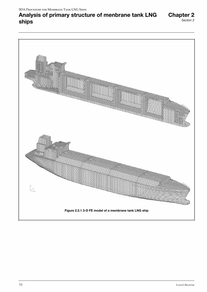
Figure 2.2.1 3-D FE model of a membrane tank LNG ship
SDA Procedure for Membrane Tank LNG Ships
Analysis of primary structure of menbrane tank LNGships
Chapter 2Section 2
10 Lloyd's Register
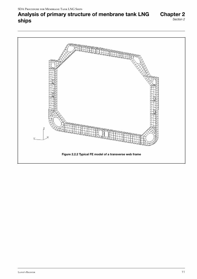
Figure 2.2.2 Typical FE model of a transverse web frame
SDA Procedure for Membrane Tank LNG Ships
Analysis of primary structure of menbrane tank LNGships
Chapter 2Section 2
Lloyd's Register 11
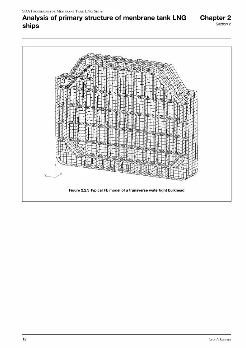
Figure 2.2.3 Typical FE model of a transverse watertight bulkhead
SDA Procedure for Membrane Tank LNG Ships
Analysis of primary structure of menbrane tank LNGships
Chapter 2Section 2
12 Lloyd's Register
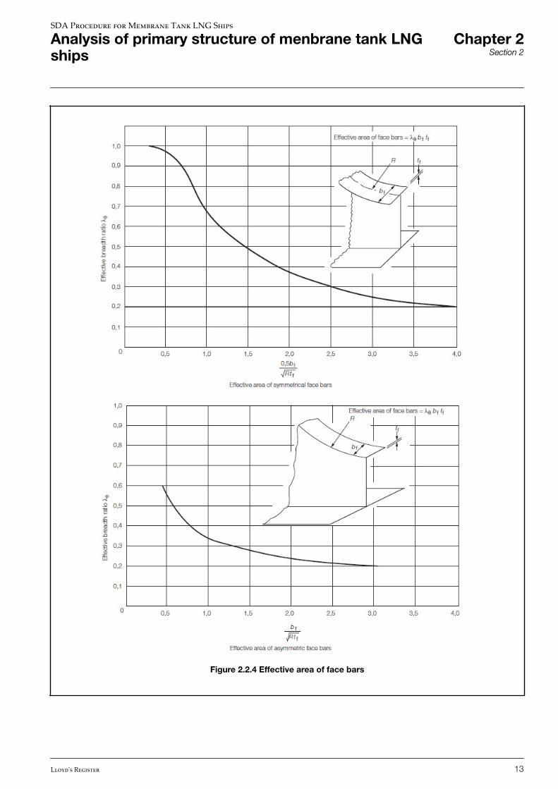
Figure 2.2.4 Effective area of face bars
SDA Procedure for Membrane Tank LNG Ships
Analysis of primary structure of menbrane tank LNGships
Chapter 2Section 2
Lloyd's Register 13
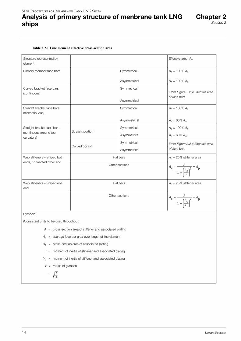
Table 2.2.1 Line element effective cross-section area
Structure represented by
element
Effective area, Ae
Primary member face bars Symmetrical Ae = 100% An
Asymmetrical Ae = 100% An
Curved bracket face bars
(continuous)
SymmetricalFrom Figure 2.2.4 Effective area
of face barsAsymmetrical
Straight bracket face bars
(discontinuous)
Symmetrical Ae = 100% An
Asymmetrical Ae = 60% An
Straight bracket face bars
(continuous around toe
curvature)
Straight portionSymmetrical Ae = 100% An
Asymmetrical Ae = 60% An
Curved portionSymmetrical From Figure 2.2.4 Effective area
of face barsAsymmetrical
Web stiffeners – Sniped both
ends, connected other end
Flat bars Ae = 25% stiffener area
Other sections �e = �1 + �o� 2 − �pWeb stiffeners – Sniped one
end,
Flat bars Ae = 75% stiffener area
Other sections �e = �1 + �o2� 2 − �pSymbols:
(Consistent units to be used throughout)
A = cross-section area of stiffener and associated plating
An = average face bar area over length of line element
Ap = cross-section area of associated plating
I = moment of inertia of stiffener and associated plating
Yo = moment of inertia of stiffener and associated plating
r = radius of gyration
= ��
SDA Procedure for Membrane Tank LNG Ships
Analysis of primary structure of menbrane tank LNGships
Chapter 2Section 2
14 Lloyd's Register
n Section 3 Boundary conditions
3.1 Introduction
3.1.1 The boundary conditions to be applied to the FE model are dependent on the load case to be analysed. Differentboundary conditions need to be applied for symmetric, asymmetric and anti-symmetric load cases.
3.1.2 The boundary conditions described in this Section include the different requirements for full-breadth and halfbreadth FEship models for the upright load cases and the requirements for a full-breadth model for the transverse load cases. It isrecommended that a full-breadth model is used for the transverse static and dynamic load cases as this simplifies the loading,boundary conditions and results post processing. However, if a half-breadth model is used for these transverse load cases,guidance on suitable boundary conditions is given in Ch 5 Appendix A: Alternative procedure for transverse load cases (half-breadth FE model).
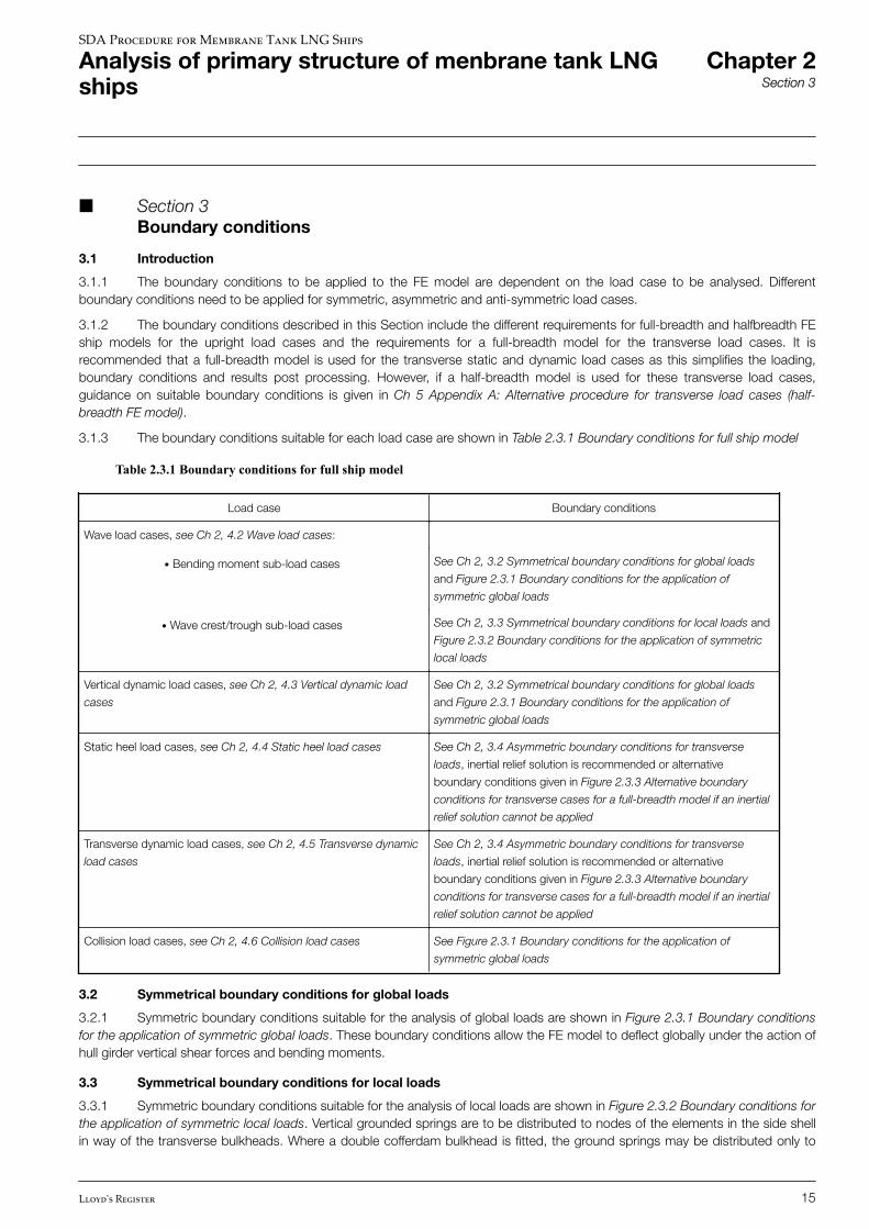
3.1.3 The boundary conditions suitable for each load case are shown in Table 2.3.1 Boundary conditions for full ship model
Table 2.3.1 Boundary conditions for full ship model
Load case Boundary conditions
Wave load cases, see Ch 2, 4.2 Wave load cases:• Bending moment sub-load cases See Ch 2, 3.2 Symmetrical boundary conditions for global loads
and Figure 2.3.1 Boundary conditions for the application of
symmetric global loads• Wave crest/trough sub-load cases See Ch 2, 3.3 Symmetrical boundary conditions for local loads and
Figure 2.3.2 Boundary conditions for the application of symmetric
local loads
Vertical dynamic load cases, see Ch 2, 4.3 Vertical dynamic load
cases
See Ch 2, 3.2 Symmetrical boundary conditions for global loads
and Figure 2.3.1 Boundary conditions for the application of
symmetric global loads
Static heel load cases, see Ch 2, 4.4 Static heel load cases See Ch 2, 3.4 Asymmetric boundary conditions for transverse
loads, inertial relief solution is recommended or alternative
boundary conditions given in Figure 2.3.3 Alternative boundary
conditions for transverse cases for a full-breadth model if an inertial
relief solution cannot be applied
Transverse dynamic load cases, see Ch 2, 4.5 Transverse dynamic
load cases
See Ch 2, 3.4 Asymmetric boundary conditions for transverse
loads, inertial relief solution is recommended or alternative
boundary conditions given in Figure 2.3.3 Alternative boundary
conditions for transverse cases for a full-breadth model if an inertial
relief solution cannot be applied
Collision load cases, see Ch 2, 4.6 Collision load cases See Figure 2.3.1 Boundary conditions for the application of
symmetric global loads
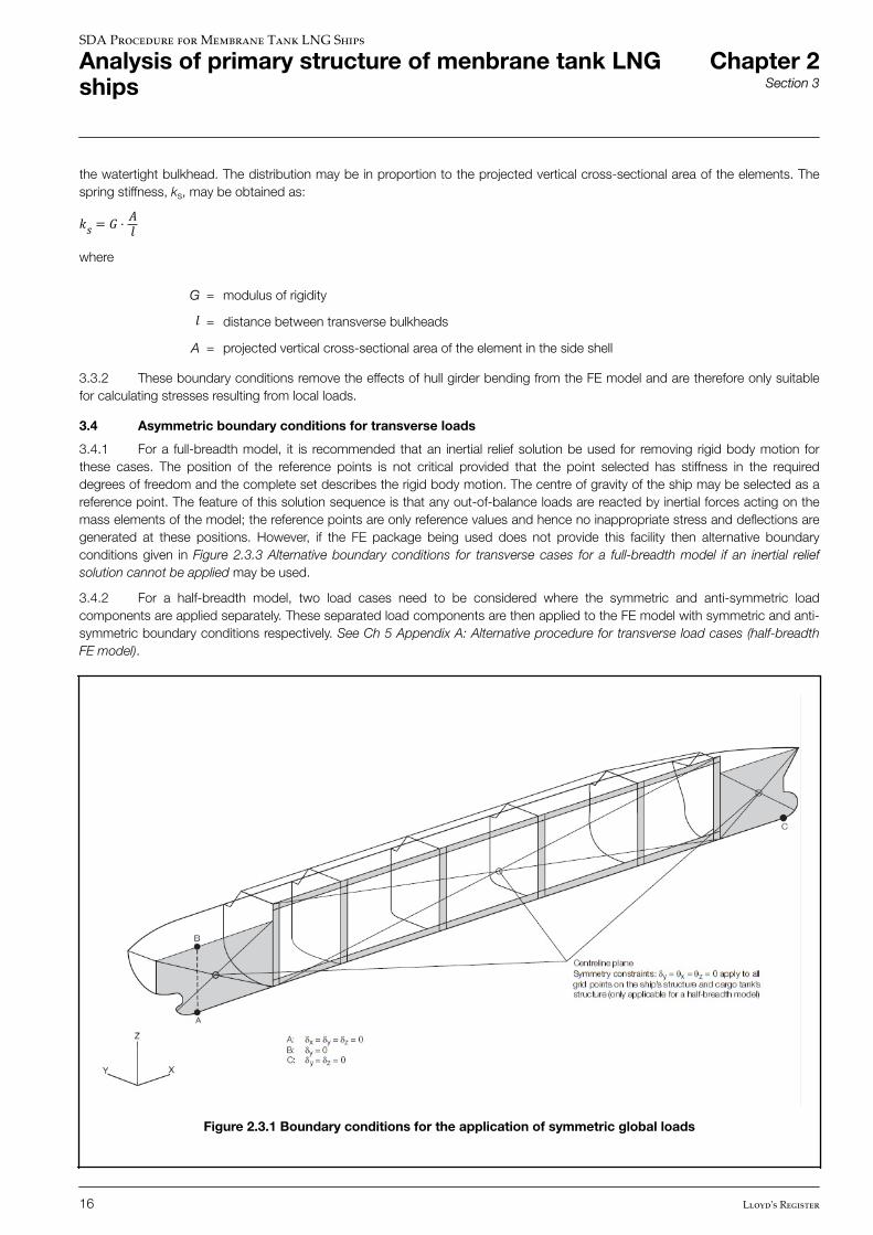
3.2 Symmetrical boundary conditions for global loads
3.2.1 Symmetric boundary conditions suitable for the analysis of global loads are shown in Figure 2.3.1 Boundary conditionsfor the application of symmetric global loads. These boundary conditions allow the FE model to deflect globally under the action ofhull girder vertical shear forces and bending moments.
3.3 Symmetrical boundary conditions for local loads
3.3.1 Symmetric boundary conditions suitable for the analysis of local loads are shown in Figure 2.3.2 Boundary conditions forthe application of symmetric local loads. Vertical grounded springs are to be distributed to nodes of the elements in the side shellin way of the transverse bulkheads. Where a double cofferdam bulkhead is fitted, the ground springs may be distributed only to
SDA Procedure for Membrane Tank LNG Ships
Analysis of primary structure of menbrane tank LNGships
Chapter 2Section 3
Lloyd's Register 15
the watertight bulkhead. The distribution may be in proportion to the projected vertical cross-sectional area of the elements. Thespring stiffness, ks, may be obtained as:�� = � ⋅ ��where
G = modulus of rigidity� = distance between transverse bulkheads
A = projected vertical cross-sectional area of the element in the side shell
3.3.2 These boundary conditions remove the effects of hull girder bending from the FE model and are therefore only suitablefor calculating stresses resulting from local loads.
3.4 Asymmetric boundary conditions for transverse loads
3.4.1 For a full-breadth model, it is recommended that an inertial relief solution be used for removing rigid body motion forthese cases. The position of the reference points is not critical provided that the point selected has stiffness in the requireddegrees of freedom and the complete set describes the rigid body motion. The centre of gravity of the ship may be selected as areference point. The feature of this solution sequence is that any out-of-balance loads are reacted by inertial forces acting on themass elements of the model; the reference points are only reference values and hence no inappropriate stress and deflections aregenerated at these positions. However, if the FE package being used does not provide this facility then alternative boundaryconditions given in Figure 2.3.3 Alternative boundary conditions for transverse cases for a full-breadth model if an inertial reliefsolution cannot be applied may be used.
3.4.2 For a half-breadth model, two load cases need to be considered where the symmetric and anti-symmetric loadcomponents are applied separately. These separated load components are then applied to the FE model with symmetric and anti-symmetric boundary conditions respectively. See Ch 5 Appendix A: Alternative procedure for transverse load cases (half-breadthFE model).
Figure 2.3.1 Boundary conditions for the application of symmetric global loads
SDA Procedure for Membrane Tank LNG Ships
Analysis of primary structure of menbrane tank LNGships
Chapter 2Section 3
16 Lloyd's Register
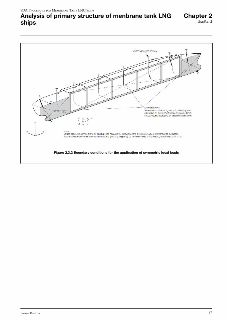
Figure 2.3.2 Boundary conditions for the application of symmetric local loads
SDA Procedure for Membrane Tank LNG Ships
Analysis of primary structure of menbrane tank LNGships
Chapter 2Section 3
Lloyd's Register 17
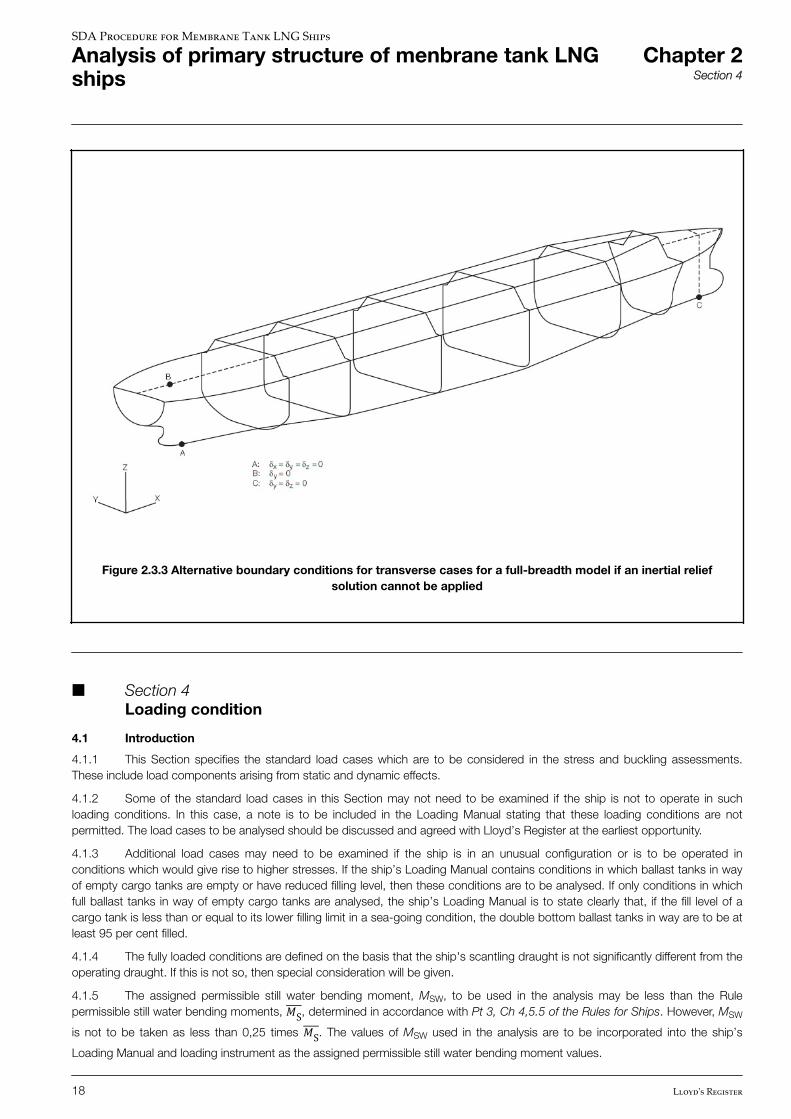
Figure 2.3.3 Alternative boundary conditions for transverse cases for a full-breadth model if an inertial reliefsolution cannot be applied
n Section 4 Loading condition
4.1 Introduction
4.1.1 This Section specifies the standard load cases which are to be considered in the stress and buckling assessments.These include load components arising from static and dynamic effects.
4.1.2 Some of the standard load cases in this Section may not need to be examined if the ship is not to operate in suchloading conditions. In this case, a note is to be included in the Loading Manual stating that these loading conditions are notpermitted. The load cases to be analysed should be discussed and agreed with Lloyd’s Register at the earliest opportunity.
4.1.3 Additional load cases may need to be examined if the ship is in an unusual configuration or is to be operated inconditions which would give rise to higher stresses. If the ship’s Loading Manual contains conditions in which ballast tanks in wayof empty cargo tanks are empty or have reduced filling level, then these conditions are to be analysed. If only conditions in whichfull ballast tanks in way of empty cargo tanks are analysed, the ship’s Loading Manual is to state clearly that, if the fill level of acargo tank is less than or equal to its lower filling limit in a sea-going condition, the double bottom ballast tanks in way are to be atleast 95 per cent filled.
4.1.4 The fully loaded conditions are defined on the basis that the ship's scantling draught is not significantly different from theoperating draught. If this is not so, then special consideration will be given.
4.1.5 The assigned permissible still water bending moment, MSW, to be used in the analysis may be less than the Rulepermissible still water bending moments, �S, determined in accordance with Pt 3, Ch 4,5.5 of the Rules for Ships. However, MSW
is not to be taken as less than 0,25 times �S. The values of MSW used in the analysis are to be incorporated into the ship’s
Loading Manual and loading instrument as the assigned permissible still water bending moment values.
SDA Procedure for Membrane Tank LNG Ships
Analysis of primary structure of menbrane tank LNGships
Chapter 2Section 4
18 Lloyd's Register
4.1.6 A ship’s loading conditions with a full load of consumables are to be considered for the analysis.
4.1.7 Unless required for contractual reasons, this SDA procedure does not require the ship’s Loading Manual to containloading conditions using the minimum cargo s.g. of 0,5. The relevant parameters for the determination of accelerationcomponents, i.e., condition draught, Cb and GM may be obtained from the review of the loading conditions presented in theLoading Manual. However, the FE analysis is to be carried out using a minimum value of cargo s.g. of 0,5.
4.2 Wave load cases
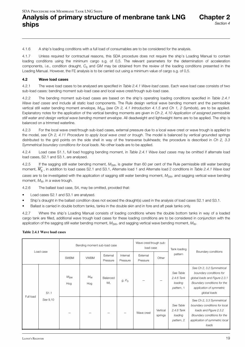
4.2.1 The wave load cases to be analysed are specified in Table 2.4.1 Wave load cases. Each wave load case consists of twosub-load cases: bending moment sub-load case and local wave crest/trough sub-load case.
4.2.2 The bending moment sub-load cases are based on the ship's operating loading conditions specified in Table 2.4.1Wave load cases and include all static load components. The Rule design vertical wave bending moment and the permissiblevertical still water bending moment envelope, MSW (see Ch 2, 4.1 Introduction 4.1.5 and Ch 1, 2 Symbols), are to be applied.Explanatory notes for the application of the vertical bending moments are given in Ch 2, 4.10 Application of assigned permissiblestill water and design vertical wave bending moment envelope. All deadweight and lightweight items are to be applied. The ship isbalanced on a trimmed waterline.
4.2.3 For the local wave crest/trough sub-load cases, external pressure due to a local wave crest or wave trough is applied tothe model, see Ch 2, 4.11 Procedure to apply local wave crest or trough. The model is balanced by vertical grounded springsdistributed to the grid points on the side shell in way of the transverse bulkheads; the procedure is described in Ch 2, 3.3Symmetrical boundary conditions for local loads. No other loads are to be applied.
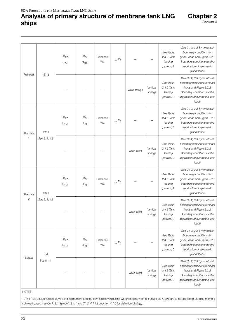
4.2.4 Load case S1.1, full load hogging bending moment, in Table 2.4.1 Wave load cases may be omitted if alternate loadload cases, S2.1 and S3.1, are analysed.
4.2.5 If the sagging still water bending moment, MSW, is greater than 60 per cent of the Rule permissible still water bendingmoment, �S , in addition to load cases S2.1 and S3.1, Alternate load 1 and Alternate load 2 conditions in Table 2.4.1 Wave load
cases are to be investigated with the application of sagging still water bending moment, MSW, and sagging vertical wave bendingmoment, MW, in a wave trough.
4.2.6 The ballast load case, S4, may be omitted, provided that:
• Load cases S2.1 and S3.1 are analysed.
• Ship’s draught in the ballast condition does not exceed the draught(s) used in the analysis of load cases S2.1 and S3.1.
• Ballast is carried in double bottom tanks, tanks in the double skin and in fore and aft peak tanks only.
4.2.7 Where the ship’s Loading Manual consists of loading conditions where the double bottom tanks in way of a loadedcargo tank are filled, additional wave trough load cases for these loading conditions are to be considered in conjunction with theapplication of the sagging still water bending moment, MSW, and sagging vertical wave bending moment, MW.
Table 2.4.1 Wave load cases
Load case
Bending moment sub-load caseWave crest/trough sub-
load case Tank loading
patternBoundary conditions
SWBM VWBMExternal
Pressure
Internal
Pressure
External
PressureOther
Full loadS1.1
See 9,10
Msw
Hog
Mw
Hog
Balanced
WLg, Po — —
See Table
2.4.6 Tank
loading
pattern, 1
See Ch 2, 3.2 Symmetrical
boundary conditions for
global loads and Figure 2.3.1
Boundary conditions for the
application of symmetric
global loads
— — — — Wave crestVertical
springs
See Table
2.4.6 Tank
loading
pattern, 2
See Ch 2, 3.3 Symmetrical
boundary conditions for local
loads and Figure 2.3.2
Boundary conditions for the
application of symmetric local
loads
SDA Procedure for Membrane Tank LNG Ships
Analysis of primary structure of menbrane tank LNGships
Chapter 2Section 4
Lloyd's Register 19
Full load S1.2
Msw
Sag
Mw
Sag
Balanced
WLg, Po — —
See Table
2.4.6 Tank
loading
pattern, 1
See Ch 2, 3.2 Symmetrical
boundary conditions for
global loads and Figure 2.3.1
Boundary conditions for the
application of symmetric
global loads
— — — — Wave troughVertical
springs
See Table
2.4.6 Tank
loading
pattern, 2
See Ch 2, 3.3 Symmetrical
boundary conditions for local
loads and Figure 2.3.2
Boundary conditions for the
application of symmetric local
loads
Alternate
1
S2.1
See 5, 7, 12
Msw
Hog
Mw
Hog
Balanced
WLg, Po — —
See Table
2.4.6 Tank
loading
pattern, 3
See Ch 2, 3.2 Symmetrical
boundary conditions for
global loads and Figure 2.3.1
Boundary conditions for the
application of symmetric
global loads
— — — — Wave crestVertical
springs
See Table
2.4.6 Tank
loading
pattern, 2
See Ch 2, 3.3 Symmetrical
boundary conditions for local
loads and Figure 2.3.2
Boundary conditions for the
application of symmetric local
loads
Alternate
2
S3.1
See 6, 7, 12
Msw
Hog
Mw
Hog
Balanced
WLg, Po — —
See Table
2.4.6 Tank
loading
pattern, 4
See Ch 2, 3.2 Symmetrical
boundary conditions for
global loads and Figure 2.3.1
Boundary conditions for the
application of symmetric
global loads
— — — — Wave crestVertical
springs
See Table
2.4.6 Tank
loading
pattern, 2
See Ch 2, 3.3 Symmetrical
boundary conditions for local
loads and Figure 2.3.2
Boundary conditions for the
application of symmetric local
loads
BallastS4
See 8, 11
Msw
Hog
Mw
Hog
Balanced
WLg, Po — —
See Table
2.4.6 Tank
loading
pattern, 5
See Ch 2, 3.2 Symmetrical
boundary conditions for
global loads and Figure 2.3.1
Boundary conditions for the
application of symmetric
global loads
— — — — Wave crestVertical
springs
See Table
2.4.6 Tank
loading
pattern, 2
See Ch 2, 3.3 Symmetrical
boundary conditions for local
loads and Figure 2.3.2
Boundary conditions for the
application of symmetric local
loads
NOTES
1. The Rule design vertical wave bending moment and the permissible vertical still water bending moment envelope, MSW, are to be applied to bending moment
sub-load cases, see Ch 1, 2.1 Symbols 2.1.1 and Ch 2, 4.1 Introduction 4.1.5 for definition of MSW.
SDA Procedure for Membrane Tank LNG Ships
Analysis of primary structure of menbrane tank LNGships
Chapter 2Section 4
20 Lloyd's Register
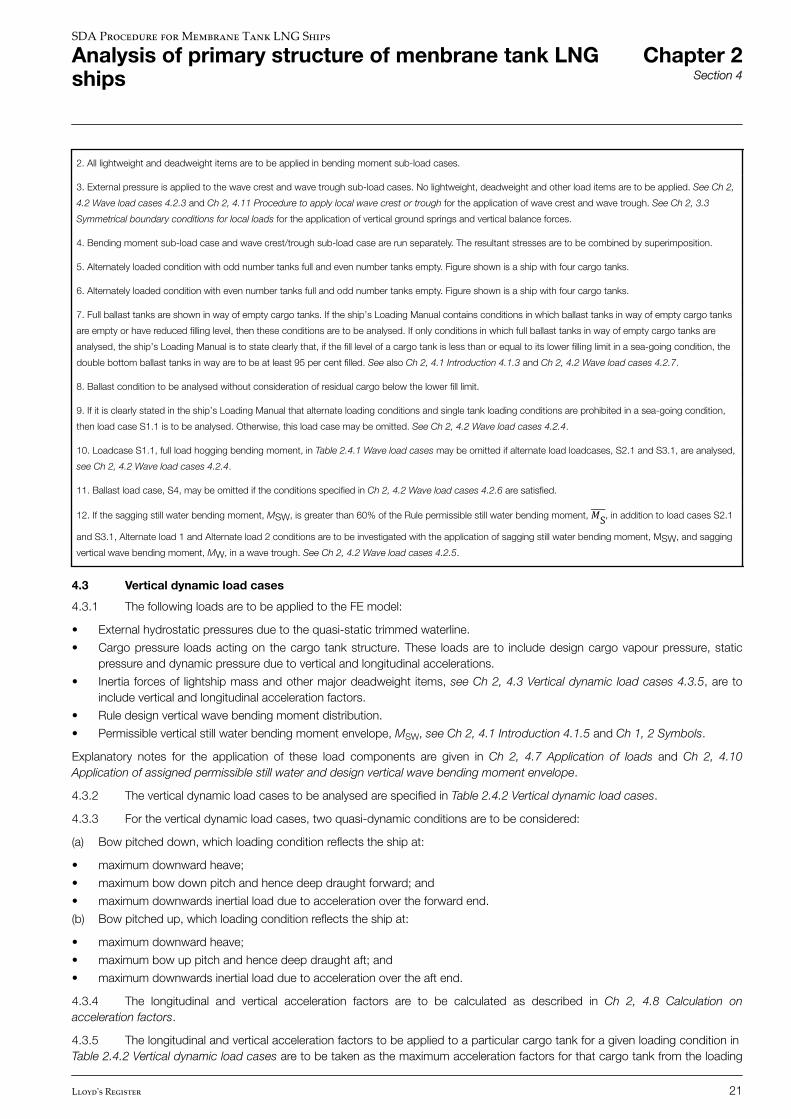
2. All lightweight and deadweight items are to be applied in bending moment sub-load cases.
3. External pressure is applied to the wave crest and wave trough sub-load cases. No lightweight, deadweight and other load items are to be applied. See Ch 2,
4.2 Wave load cases 4.2.3 and Ch 2, 4.11 Procedure to apply local wave crest or trough for the application of wave crest and wave trough. See Ch 2, 3.3
Symmetrical boundary conditions for local loads for the application of vertical ground springs and vertical balance forces.
4. Bending moment sub-load case and wave crest/trough sub-load case are run separately. The resultant stresses are to be combined by superimposition.
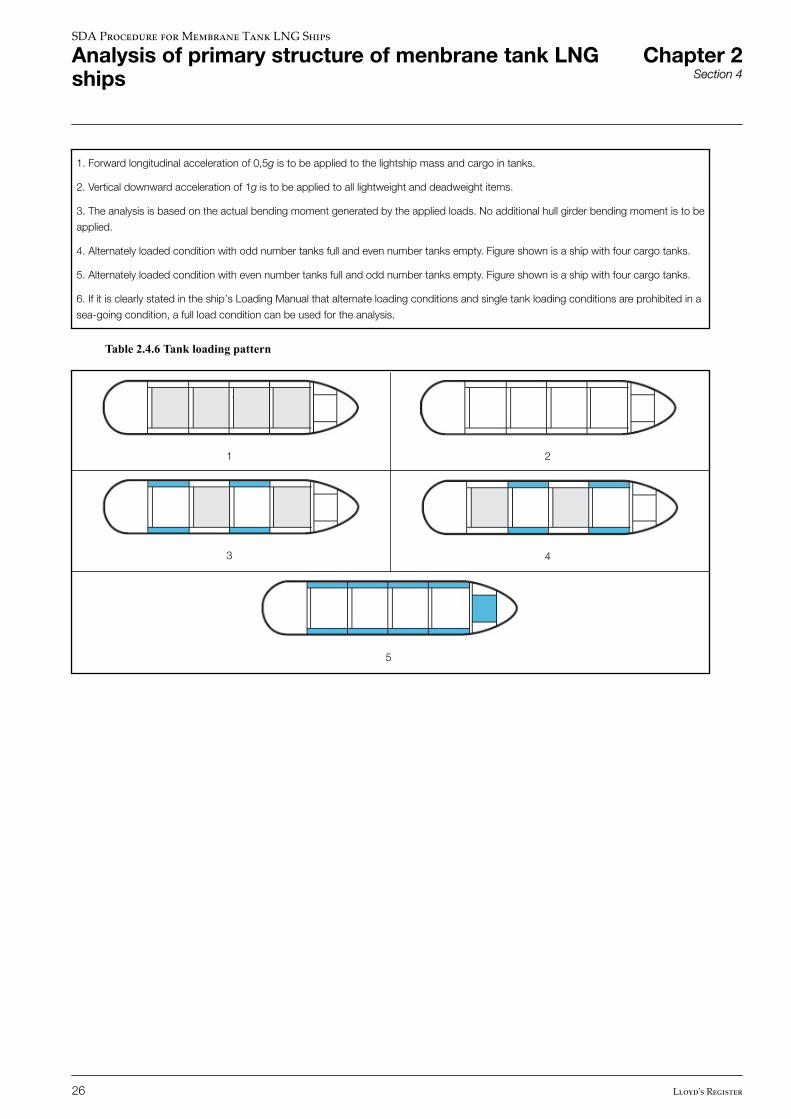
5. Alternately loaded condition with odd number tanks full and even number tanks empty. Figure shown is a ship with four cargo tanks.
6. Alternately loaded condition with even number tanks full and odd number tanks empty. Figure shown is a ship with four cargo tanks.
7. Full ballast tanks are shown in way of empty cargo tanks. If the ship’s Loading Manual contains conditions in which ballast tanks in way of empty cargo tanks
are empty or have reduced filling level, then these conditions are to be analysed. If only conditions in which full ballast tanks in way of empty cargo tanks are
analysed, the ship’s Loading Manual is to state clearly that, if the fill level of a cargo tank is less than or equal to its lower filling limit in a sea-going condition, the
double bottom ballast tanks in way are to be at least 95 per cent filled. See also Ch 2, 4.1 Introduction 4.1.3 and Ch 2, 4.2 Wave load cases 4.2.7.
8. Ballast condition to be analysed without consideration of residual cargo below the lower fill limit.
9. If it is clearly stated in the ship’s Loading Manual that alternate loading conditions and single tank loading conditions are prohibited in a sea-going condition,
then load case S1.1 is to be analysed. Otherwise, this load case may be omitted. See Ch 2, 4.2 Wave load cases 4.2.4.
10. Loadcase S1.1, full load hogging bending moment, in Table 2.4.1 Wave load cases may be omitted if alternate load loadcases, S2.1 and S3.1, are analysed,
see Ch 2, 4.2 Wave load cases 4.2.4.
11. Ballast load case, S4, may be omitted if the conditions specified in Ch 2, 4.2 Wave load cases 4.2.6 are satisfied.
12. If the sagging still water bending moment, MSW, is greater than 60% of the Rule permissible still water bending moment, �S, in addition to load cases S2.1
and S3.1, Alternate load 1 and Alternate load 2 conditions are to be investigated with the application of sagging still water bending moment, MSW, and sagging
vertical wave bending moment, MW, in a wave trough. See Ch 2, 4.2 Wave load cases 4.2.5.
4.3 Vertical dynamic load cases
4.3.1 The following loads are to be applied to the FE model:
• External hydrostatic pressures due to the quasi-static trimmed waterline.
• Cargo pressure loads acting on the cargo tank structure. These loads are to include design cargo vapour pressure, staticpressure and dynamic pressure due to vertical and longitudinal accelerations.
• Inertia forces of lightship mass and other major deadweight items, see Ch 2, 4.3 Vertical dynamic load cases 4.3.5, are toinclude vertical and longitudinal acceleration factors.
• Rule design vertical wave bending moment distribution.
• Permissible vertical still water bending moment envelope, MSW, see Ch 2, 4.1 Introduction 4.1.5 and Ch 1, 2 Symbols.
Explanatory notes for the application of these load components are given in Ch 2, 4.7 Application of loads and Ch 2, 4.10Application of assigned permissible still water and design vertical wave bending moment envelope.
4.3.2 The vertical dynamic load cases to be analysed are specified in Table 2.4.2 Vertical dynamic load cases.
4.3.3 For the vertical dynamic load cases, two quasi-dynamic conditions are to be considered:
(a) Bow pitched down, which loading condition reflects the ship at:
• maximum downward heave;
• maximum bow down pitch and hence deep draught forward; and
• maximum downwards inertial load due to acceleration over the forward end.
(b) Bow pitched up, which loading condition reflects the ship at:
• maximum downward heave;
• maximum bow up pitch and hence deep draught aft; and
• maximum downwards inertial load due to acceleration over the aft end.
4.3.4 The longitudinal and vertical acceleration factors are to be calculated as described in Ch 2, 4.8 Calculation onacceleration factors.
4.3.5 The longitudinal and vertical acceleration factors to be applied to a particular cargo tank for a given loading condition in Table 2.4.2 Vertical dynamic load cases are to be taken as the maximum acceleration factors for that cargo tank from the loading
SDA Procedure for Membrane Tank LNG Ships
Analysis of primary structure of menbrane tank LNGships
Chapter 2Section 4
Lloyd's Register 21
conditions in the ship’s Loading Manual with the same loading pattern. Attention is to be paid to ensuring that the correctmaximum vertical accelerations are used for bow pitched up and bow pitched down cases. See Ch 2, 4.8 Calculation onacceleration factors 4.8.3.
4.3.6 The acceleration factors to be applied to other large volume tanks, such as ballast tanks and fuel oil tanks, are to bedetermined in a similar manner as given in Ch 2, 4.3 Vertical dynamic load cases 4.3.4 and Ch 2, 4.3 Vertical dynamic load cases4.3.5. However, the loading conditions considered may be limited to those used to determine the cargo tank acceleration factors.When calculating the acceleration factors for particular tank, the centre of gravity of that tank is to be used. It is not necessary toapply acceleration factors to small tanks such as fresh-water tanks, daily-use tanks, lubrication oil tanks, etc.
4.3.7 Longitudinal and vertical acceleration factors are also to be applied to the ship light mass. To simplify the application ofthese acceleration factors, large equipment items should be represented as mass elements. If the FE package being used doesnot support the application of varying acceleration values, alternative methods should be discussed with the local Lloyd’s RegisterOffice.
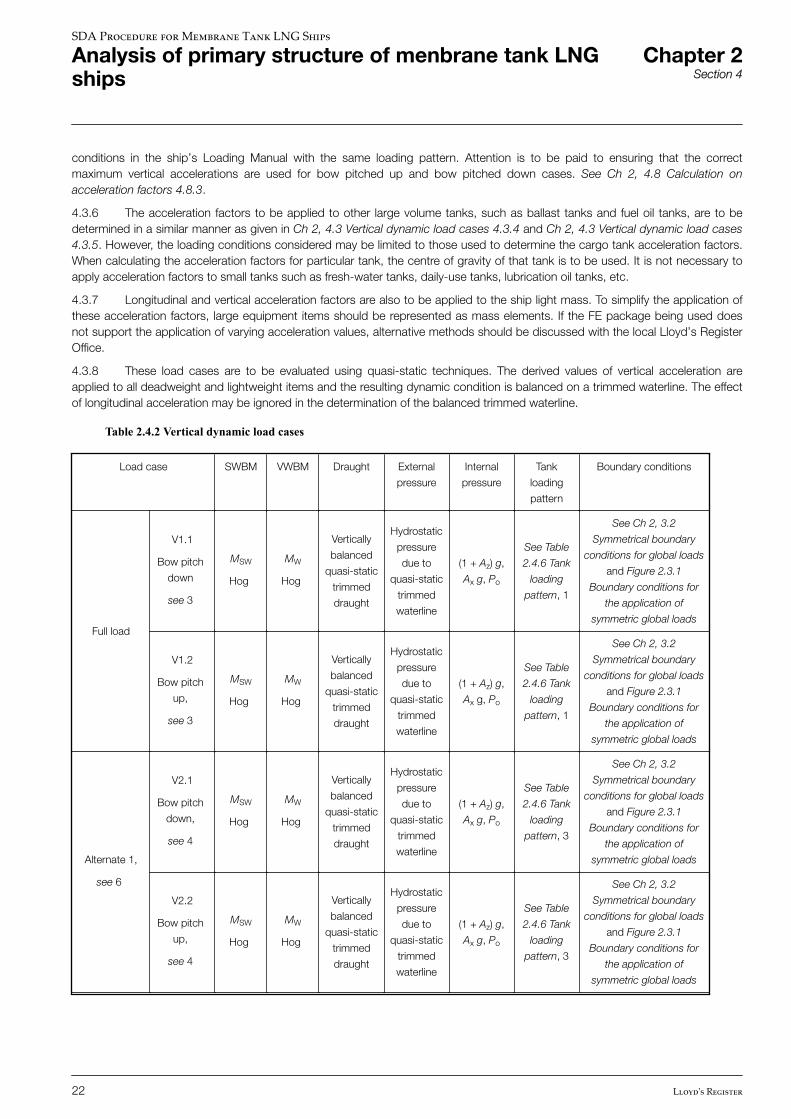
4.3.8 These load cases are to be evaluated using quasi-static techniques. The derived values of vertical acceleration areapplied to all deadweight and lightweight items and the resulting dynamic condition is balanced on a trimmed waterline. The effectof longitudinal acceleration may be ignored in the determination of the balanced trimmed waterline.
Table 2.4.2 Vertical dynamic load cases
Load case SWBM VWBM Draught External
pressure
Internal
pressure
Tank
loading
pattern
Boundary conditions
Full load
V1.1
Bow pitch
down
see 3
MSW
Hog
MW
Hog
Vertically
balanced
quasi-static
trimmed
draught
Hydrostatic
pressure
due to
quasi-static
trimmed
waterline
(1 + Az) g,
Ax g, Po
See Table
2.4.6 Tank
loading
pattern, 1
See Ch 2, 3.2
Symmetrical boundary
conditions for global loads
and Figure 2.3.1
Boundary conditions for
the application of
symmetric global loads
V1.2
Bow pitch
up,
see 3
MSW
Hog
MW
Hog
Vertically
balanced
quasi-static
trimmed
draught
Hydrostatic
pressure
due to
quasi-static
trimmed
waterline
(1 + Az) g,
Ax g, Po
See Table
2.4.6 Tank
loading
pattern, 1
See Ch 2, 3.2
Symmetrical boundary
conditions for global loads
and Figure 2.3.1
Boundary conditions for
the application of
symmetric global loads
Alternate 1,
see 6
V2.1
Bow pitch
down,
see 4
MSW
Hog
MW
Hog
Vertically
balanced
quasi-static
trimmed
draught
Hydrostatic
pressure
due to
quasi-static
trimmed
waterline
(1 + Az) g,
Ax g, Po
See Table
2.4.6 Tank
loading
pattern, 3
See Ch 2, 3.2
Symmetrical boundary
conditions for global loads
and Figure 2.3.1
Boundary conditions for
the application of
symmetric global loads
V2.2
Bow pitch
up,
see 4
MSW
Hog
MW
Hog
Vertically
balanced
quasi-static
trimmed
draught
Hydrostatic
pressure
due to
quasi-static
trimmed
waterline
(1 + Az) g,
Ax g, Po
See Table
2.4.6 Tank
loading
pattern, 3
See Ch 2, 3.2
Symmetrical boundary
conditions for global loads
and Figure 2.3.1
Boundary conditions for
the application of
symmetric global loads
SDA Procedure for Membrane Tank LNG Ships
Analysis of primary structure of menbrane tank LNGships
Chapter 2Section 4
22 Lloyd's Register
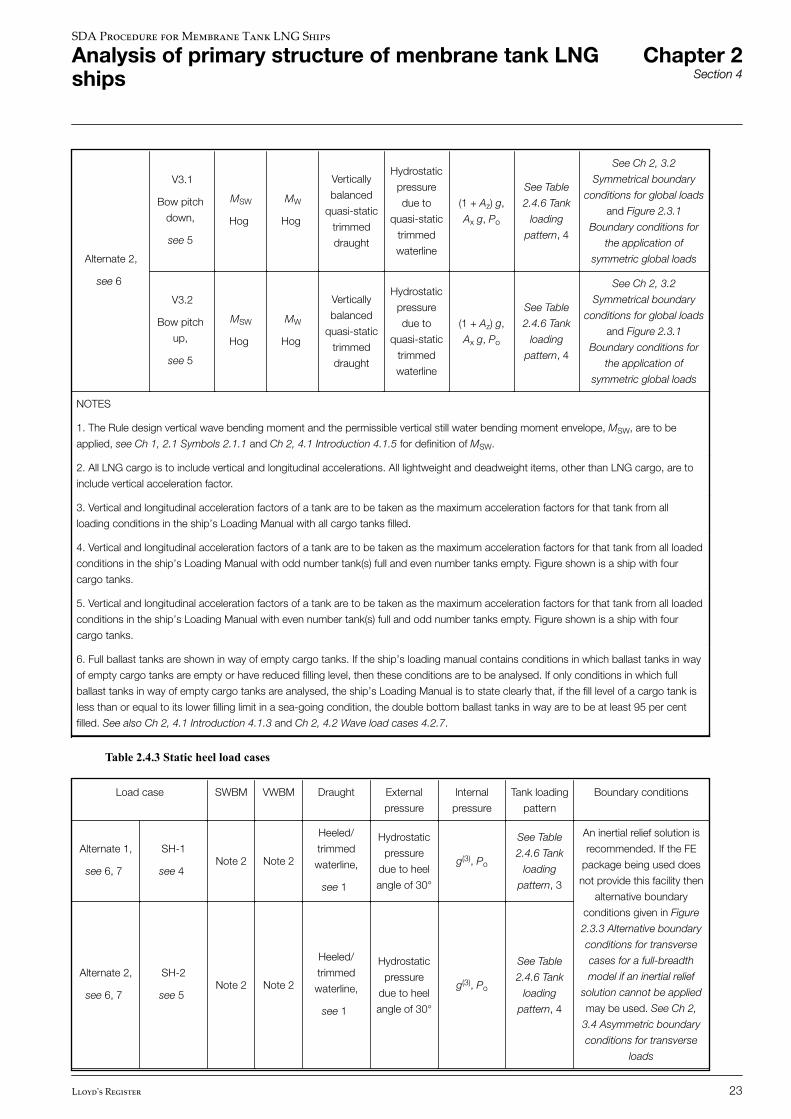
Alternate 2,
see 6
V3.1
Bow pitch
down,
see 5
MSW
Hog
MW
Hog
Vertically
balanced
quasi-static
trimmed
draught
Hydrostatic
pressure
due to
quasi-static
trimmed
waterline
(1 + Az) g,
Ax g, Po
See Table
2.4.6 Tank
loading
pattern, 4
See Ch 2, 3.2
Symmetrical boundary
conditions for global loads
and Figure 2.3.1
Boundary conditions for
the application of
symmetric global loads
V3.2
Bow pitch
up,
see 5
MSW
Hog
MW
Hog
Vertically
balanced
quasi-static
trimmed
draught
Hydrostatic
pressure
due to
quasi-static
trimmed
waterline
(1 + Az) g,
Ax g, Po
See Table
2.4.6 Tank
loading
pattern, 4
See Ch 2, 3.2
Symmetrical boundary
conditions for global loads
and Figure 2.3.1
Boundary conditions for
the application of
symmetric global loads
NOTES
1. The Rule design vertical wave bending moment and the permissible vertical still water bending moment envelope, MSW, are to be
applied, see Ch 1, 2.1 Symbols 2.1.1 and Ch 2, 4.1 Introduction 4.1.5 for definition of MSW.
2. All LNG cargo is to include vertical and longitudinal accelerations. All lightweight and deadweight items, other than LNG cargo, are to
include vertical acceleration factor.
3. Vertical and longitudinal acceleration factors of a tank are to be taken as the maximum acceleration factors for that tank from all
loading conditions in the ship’s Loading Manual with all cargo tanks filled.
4. Vertical and longitudinal acceleration factors of a tank are to be taken as the maximum acceleration factors for that tank from all loaded
conditions in the ship’s Loading Manual with odd number tank(s) full and even number tanks empty. Figure shown is a ship with four
cargo tanks.
5. Vertical and longitudinal acceleration factors of a tank are to be taken as the maximum acceleration factors for that tank from all loaded
conditions in the ship’s Loading Manual with even number tank(s) full and odd number tanks empty. Figure shown is a ship with four
cargo tanks.
6. Full ballast tanks are shown in way of empty cargo tanks. If the ship’s loading manual contains conditions in which ballast tanks in way
of empty cargo tanks are empty or have reduced filling level, then these conditions are to be analysed. If only conditions in which full
ballast tanks in way of empty cargo tanks are analysed, the ship’s Loading Manual is to state clearly that, if the fill level of a cargo tank is
less than or equal to its lower filling limit in a sea-going condition, the double bottom ballast tanks in way are to be at least 95 per cent
filled. See also Ch 2, 4.1 Introduction 4.1.3 and Ch 2, 4.2 Wave load cases 4.2.7.
Table 2.4.3 Static heel load cases
Load case SWBM VWBM Draught External
pressure
Internal
pressure
Tank loading
pattern
Boundary conditions
Alternate 1,
see 6, 7
SH-1
see 4Note 2 Note 2
Heeled/
trimmed
waterline,
see 1
Hydrostatic
pressure
due to heel
angle of 30°
g(3), Po
See Table
2.4.6 Tank
loading
pattern, 3
An inertial relief solution is
recommended. If the FE
package being used does
not provide this facility then
alternative boundary
conditions given in Figure
2.3.3 Alternative boundary
conditions for transverse
cases for a full-breadth
model if an inertial relief
solution cannot be applied
may be used. See Ch 2,
3.4 Asymmetric boundary
conditions for transverse
loads
Alternate 2,
see 6, 7
SH-2
see 5Note 2 Note 2
Heeled/
trimmed
waterline,
see 1
Hydrostatic
pressure
due to heel
angle of 30°
g(3), Po
See Table
2.4.6 Tank
loading
pattern, 4
SDA Procedure for Membrane Tank LNG Ships
Analysis of primary structure of menbrane tank LNGships
Chapter 2Section 4
Lloyd's Register 23
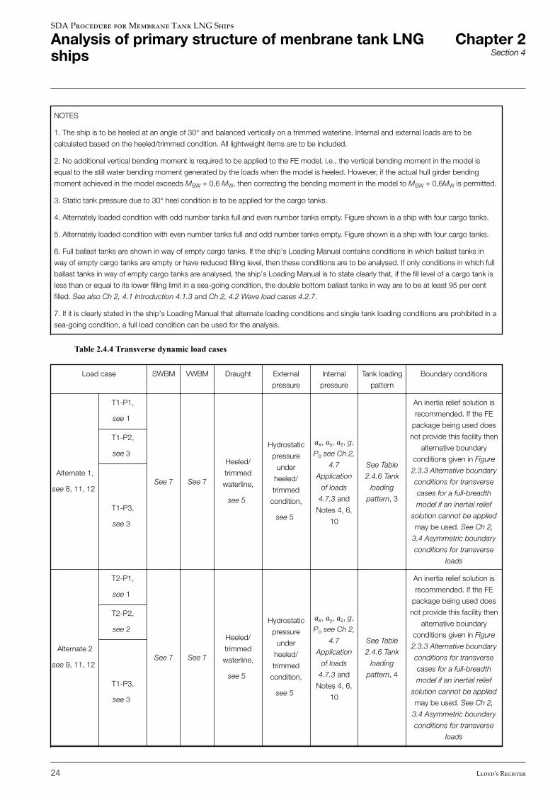
NOTES
1. The ship is to be heeled at an angle of 30° and balanced vertically on a trimmed waterline. Internal and external loads are to be
calculated based on the heeled/trimmed condition. All lightweight items are to be included.
2. No additional vertical bending moment is required to be applied to the FE model, i.e., the vertical bending moment in the model is
equal to the still water bending moment generated by the loads when the model is heeled. However, if the actual hull girder bending
moment achieved in the model exceeds MSW + 0,6 MW, then correcting the bending moment in the model to MSW + 0,6MW is permitted.
3. Static tank pressure due to 30° heel condition is to be applied for the cargo tanks.
4. Alternately loaded condition with odd number tanks full and even number tanks empty. Figure shown is a ship with four cargo tanks.
5. Alternately loaded condition with even number tanks full and odd number tanks empty. Figure shown is a ship with four cargo tanks.
6. Full ballast tanks are shown in way of empty cargo tanks. If the ship’s Loading Manual contains conditions in which ballast tanks in
way of empty cargo tanks are empty or have reduced filling level, then these conditions are to be analysed. If only conditions in which full
ballast tanks in way of empty cargo tanks are analysed, the ship’s Loading Manual is to state clearly that, if the fill level of a cargo tank is
less than or equal to its lower filling limit in a sea-going condition, the double bottom ballast tanks in way are to be at least 95 per cent
filled. See also Ch 2, 4.1 Introduction 4.1.3 and Ch 2, 4.2 Wave load cases 4.2.7.
7. If it is clearly stated in the ship’s Loading Manual that alternate loading conditions and single tank loading conditions are prohibited in a
sea-going condition, a full load condition can be used for the analysis.
Table 2.4.4 Transverse dynamic load cases
Load case SWBM VWBM Draught External
pressure
Internal
pressure
Tank loading
pattern
Boundary conditions
Alternate 1,
see 8, 11, 12
T1-P1,
see 1
See 7 See 7
Heeled/
trimmed
waterline,
see 5
Hydrostatic
pressure
under
heeled/
trimmed
condition,
see 5
�x, �y, �z, g,
Po see Ch 2,
4.7
Application
of loads
4.7.3 and
Notes 4, 6,
10
See Table
2.4.6 Tank
loading
pattern, 3
An inertia relief solution is
recommended. If the FE
package being used does
not provide this facility then
alternative boundary
conditions given in Figure
2.3.3 Alternative boundary
conditions for transverse
cases for a full-breadth
model if an inertial relief
solution cannot be applied
may be used. See Ch 2,
3.4 Asymmetric boundary
conditions for transverse
loads
T1-P2,
see 3
T1-P3,
see 3
Alternate 2
see 9, 11, 12
T2-P1,
see 1
See 7 See 7
Heeled/
trimmed
waterline,
see 5
Hydrostatic
pressure
under
heeled/
trimmed
condition,
see 5
�x, �y, �z, g,
Po see Ch 2,
4.7
Application
of loads
4.7.3 and
Notes 4, 6,
10
See Table
2.4.6 Tank
loading
pattern, 4
An inertia relief solution is
recommended. If the FE
package being used does
not provide this facility then
alternative boundary
conditions given in Figure
2.3.3 Alternative boundary
conditions for transverse
cases for a full-breadth
model if an inertial relief
solution cannot be applied
may be used. See Ch 2,
3.4 Asymmetric boundary
conditions for transverse
loads
T2-P2,
see 2
T1-P3,
see 3
SDA Procedure for Membrane Tank LNG Ships
Analysis of primary structure of menbrane tank LNGships
Chapter 2Section 4
24 Lloyd's Register
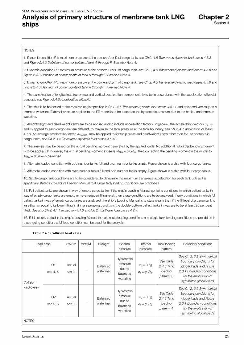
NOTES
1. Dynamic condition P1: maximum pressure at the corners A or D of cargo tank, see Ch 2, 4.5 Transverse dynamic load cases 4.5.8
and Figure 2.4.3 Definition of corner points of tank A through F. See also Note 4.
2. Dynamic condition P2: maximum pressure at the corners B or E of cargo tank, see Ch 2, 4.5 Transverse dynamic load cases 4.5.8 and
Figure 2.4.3 Definition of corner points of tank A through F. See also Note 4.
3. Dynamic condition P3: maximum pressure at the corners C or F of cargo tank, see Ch 2, 4.5 Transverse dynamic load cases 4.5.8 and
Figure 2.4.3 Definition of corner points of tank A through F. See also Note 4.
4. The combination of longitudinal, transverse and vertical acceleration components is to be in accordance with the acceleration ellipsoid
concept, see Figure 2.4.2 Acceleration ellipsoid.
5. The ship is to be heeled at the required angle specified in Ch 2, 4.5 Transverse dynamic load cases 4.5.11 and balanced vertically on a
trimmed waterline. External pressure applied to the FE model is to be based on the hydrostatic pressure due to the heeled and trimmed
waterline.
6. All lightweight and deadweight items are to be applied and to include acceleration factors. In general, the acceleration vectors �x, �y
and �z applied to each cargo tank are different, to maximise the tank pressure at the tank boundary, see Ch 2, 4.7 Application of loads
4.7.3. An average acceleration factor, �average, may be applied to lightship mass and deadweight items other than for the contents in
cargo tanks, see Ch 2, 4.5 Transverse dynamic load cases 4.5.12.
7. The analysis may be based on the actual bending moment generated by the applied loads. No additional hull girder bending moment
is to be applied. If, however, the actual bending moment exceeds MSW + 0,6MW, then correcting the bending moment in the model to
MSW + 0,6MW is permitted.
8. Alternate loaded condition with odd number tanks full and even number tanks empty. Figure shown is a ship with four cargo tanks.
9. Alternate loaded condition with even number tanks full and odd number tanks empty. Figure shown is a ship with four cargo tanks.
10. Single cargo tank conditions are to be considered to determine the maximum transverse acceleration for each tank unless it is
specifically stated in the ship's Loading Manual that single tank loading conditions are prohibited.
11. Full ballast tanks are shown in way of empty cargo tanks. If the ship’s Loading Manual contains conditions in which ballast tanks in
way of empty cargo tanks are empty or have reduced filling level, then these conditions are to be analysed. If only conditions in which full
ballast tanks in way of empty cargo tanks are analysed, the ship’s Loading Manual is to state clearly that, if the fill level of a cargo tank is
less than or equal to its lower filling limit in a sea-going condition, the double bottom ballast tanks in way are to be at least 95 per cent
filled. See also Ch 2, 4.1 Introduction 4.1.3 and Ch 2, 4.2 Wave load cases 4.2.7.
12. If it is clearly stated in the ship’s Loading Manual that alternate loading conditions and single tank loading conditions are prohibited in
a sea-going condition, a full load condition can be used for the analysis.
Table 2.4.5 Collision load cases
Load case SWBM VWBM Draught External
pressure
Internal
pressure
Tank loading
pattern
Boundary conditions
Collision
load cases
O1
see 4, 6
Actual
see 3—
Balanced
waterline,
Hydrostatic
pressure
due to
balanced
waterline
�x = 0,5g�z = g, Po
See Table
2.4.6 Tank
loading
pattern, 3
See Ch 2, 3.2 Symmetrical
boundary conditions for
global loads and Figure
2.3.1 Boundary conditions
for the application of
symmetric global loads
O2
see 5, 6
Actual
see 3—
Balanced
waterline,
Hydrostatic
pressure
due to
balanced
waterline
�x = 0,5g�z = g, Po
See Table
2.4.6 Tank
loading
pattern, 4
See Ch 2, 3.2 Symmetrical
boundary conditions for
global loads and Figure
2.3.1 Boundary conditions
for the application of
symmetric global loads
NOTES
SDA Procedure for Membrane Tank LNG Ships
Analysis of primary structure of menbrane tank LNGships
Chapter 2Section 4
Lloyd's Register 25
1. Forward longitudinal acceleration of 0,5g is to be applied to the lightship mass and cargo in tanks.
2. Vertical downward acceleration of 1g is to be applied to all lightweight and deadweight items.
3. The analysis is based on the actual bending moment generated by the applied loads. No additional hull girder bending moment is to be
applied.
4. Alternately loaded condition with odd number tanks full and even number tanks empty. Figure shown is a ship with four cargo tanks.
5. Alternately loaded condition with even number tanks full and odd number tanks empty. Figure shown is a ship with four cargo tanks.
6. If it is clearly stated in the ship’s Loading Manual that alternate loading conditions and single tank loading conditions are prohibited in a
sea-going condition, a full load condition can be used for the analysis.
Table 2.4.6 Tank loading pattern
1 2
3 4
5
SDA Procedure for Membrane Tank LNG Ships
Analysis of primary structure of menbrane tank LNGships
Chapter 2Section 4
26 Lloyd's Register
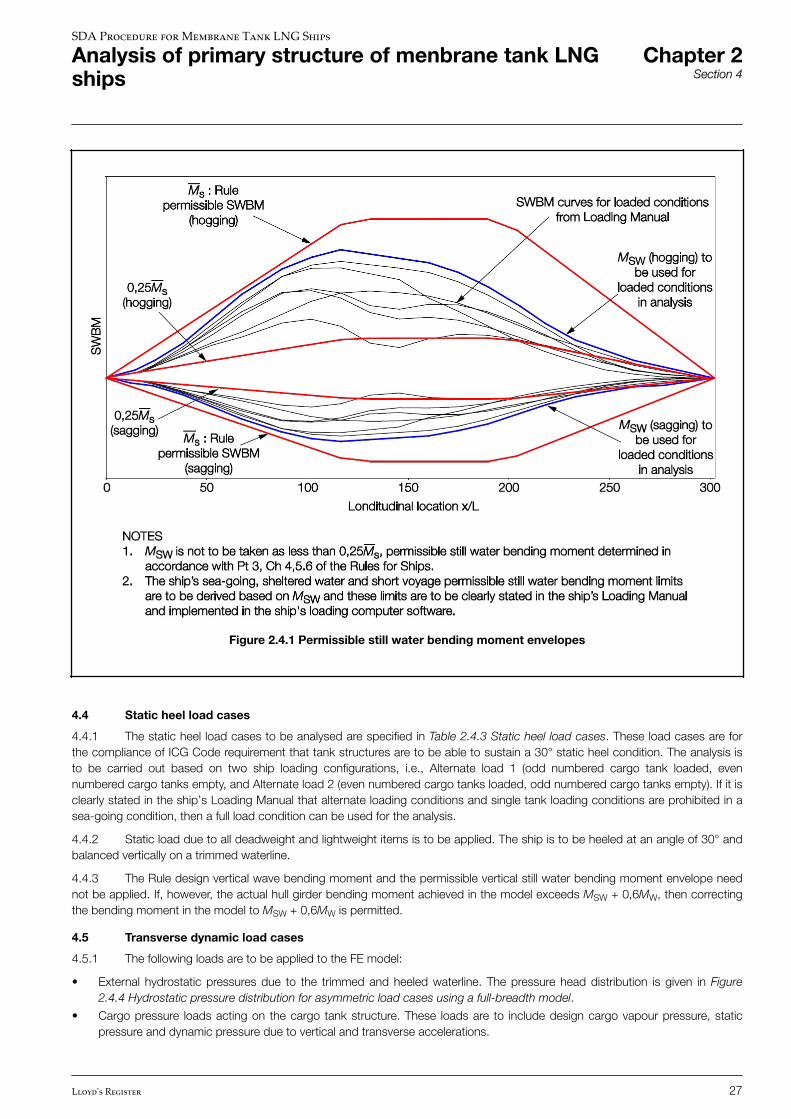
Figure 2.4.1 Permissible still water bending moment envelopes
4.4 Static heel load cases
4.4.1 The static heel load cases to be analysed are specified in Table 2.4.3 Static heel load cases. These load cases are forthe compliance of ICG Code requirement that tank structures are to be able to sustain a 30° static heel condition. The analysis isto be carried out based on two ship loading configurations, i.e., Alternate load 1 (odd numbered cargo tank loaded, evennumbered cargo tanks empty, and Alternate load 2 (even numbered cargo tanks loaded, odd numbered cargo tanks empty). If it isclearly stated in the ship’s Loading Manual that alternate loading conditions and single tank loading conditions are prohibited in asea-going condition, then a full load condition can be used for the analysis.
4.4.2 Static load due to all deadweight and lightweight items is to be applied. The ship is to be heeled at an angle of 30° andbalanced vertically on a trimmed waterline.
4.4.3 The Rule design vertical wave bending moment and the permissible vertical still water bending moment envelope neednot be applied. If, however, the actual hull girder bending moment achieved in the model exceeds MSW + 0,6MW, then correctingthe bending moment in the model to MSW + 0,6MW is permitted.
4.5 Transverse dynamic load cases
4.5.1 The following loads are to be applied to the FE model:
• External hydrostatic pressures due to the trimmed and heeled waterline. The pressure head distribution is given in Figure2.4.4 Hydrostatic pressure distribution for asymmetric load cases using a full-breadth model.
• Cargo pressure loads acting on the cargo tank structure. These loads are to include design cargo vapour pressure, staticpressure and dynamic pressure due to vertical and transverse accelerations.
SDA Procedure for Membrane Tank LNG Ships
Analysis of primary structure of menbrane tank LNGships
Chapter 2Section 4
Lloyd's Register 27
• Inertia forces of lightship mass and other deadweight items are to include transverse and vertical acceleration factors, see Ch2, 4.5 Transverse dynamic load cases 4.5.12.
Components shown are acceleration factors based on acceleration 1g
• Bending moment correction, if required, see Ch 2, 4.5 Transverse dynamic load cases 4.5.14. Explanatory notes regardingthe derivation and application of these load components are given in Ch 2, 4.10 Application of assigned permissible stillwater and design vertical wave bending moment envelope.
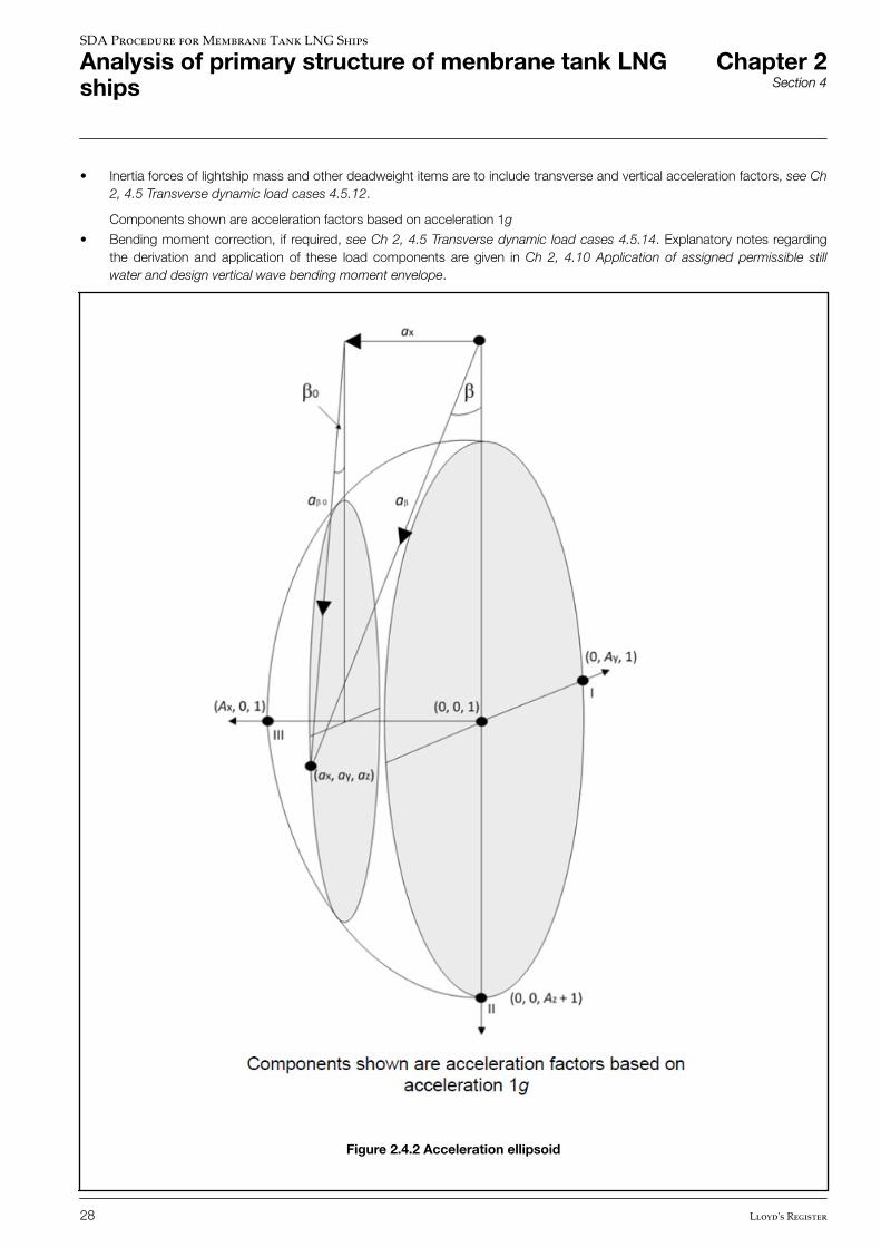
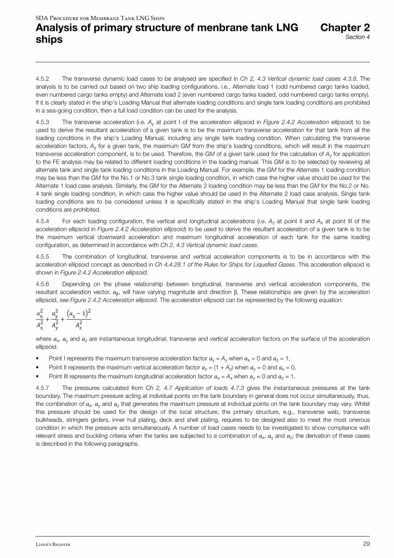
Figure 2.4.2 Acceleration ellipsoid
SDA Procedure for Membrane Tank LNG Ships
Analysis of primary structure of menbrane tank LNGships
Chapter 2Section 4
28 Lloyd's Register
4.5.2 The transverse dynamic load cases to be analysed are specified in Ch 2, 4.3 Vertical dynamic load cases 4.3.8. Theanalysis is to be carried out based on two ship loading configurations, i.e., Alternate load 1 (odd numbered cargo tanks loaded,even numbered cargo tanks empty) and Alternate load 2 (even numbered cargo tanks loaded, odd numbered cargo tanks empty).If it is clearly stated in the ship’s Loading Manual that alternate loading conditions and single tank loading conditions are prohibitedin a sea-going condition, then a full load condition can be used for the analysis.
4.5.3 The transverse acceleration (i.e. Ay at point I of the acceleration ellipsoid in Figure 2.4.2 Acceleration ellipsoid) to beused to derive the resultant acceleration of a given tank is to be the maximum transverse acceleration for that tank from all theloading conditions in the ship’s Loading Manual, including any single tank loading condition. When calculating the transverseacceleration factors, Ay for a given tank, the maximum GM from the ship’s loading conditions, which will result in the maximumtransverse acceleration component, is to be used. Therefore, the GM of a given tank used for the calculation of Ay for applicationto the FE analysis may be related to different loading conditions in the loading manual. This GM is to be selected by reviewing allalternate tank and single tank loading conditions in the Loading Manual. For example, the GM for the Alternate 1 loading conditionmay be less than the GM for the No.1 or No.3 tank single loading condition, in which case the higher value should be used for theAlternate 1 load case analysis. Similarly, the GM for the Alternate 2 loading condition may be less than the GM for the No.2 or No.4 tank single loading condition, in which case the higher value should be used in the Alternate 2 load case analysis. Single tankloading conditions are to be considered unless it is specifically stated in the ship's Loading Manual that single tank loadingconditions are prohibited.
4.5.4 For each loading configuration, the vertical and longitudinal accelerations (i.e. Az at point II and Ax at point III of theacceleration ellipsoid in Figure 2.4.2 Acceleration ellipsoid) to be used to derive the resultant acceleration of a given tank is to bethe maximum vertical downward acceleration and maximum longitudinal acceleration of each tank for the same loadingconfiguration, as determined in accordance with Ch 2, 4.3 Vertical dynamic load cases.
4.5.5 The combination of longitudinal, transverse and vertical acceleration components is to be in accordance with theacceleration ellipsoid concept as described in Ch 4,4.28.1 of the Rules for Ships for Liquefied Gases. This acceleration ellipsoid isshown in Figure 2.4.2 Acceleration ellipsoid.
4.5.6 Depending on the phase relationship between longitudinal, transverse and vertical acceleration components, theresultant acceleration vector, �β, will have varying magnitude and direction β. These relationships are given by the accelerationellipsoid, see Figure 2.4.2 Acceleration ellipsoid. The acceleration ellipsoid can be represented by the following equation:�x2�x2 + �y2�y2 + �z− 1 2�z2where �x, �y and �z are instantaneous longitudinal, transverse and vertical acceleration factors on the surface of the accelerationellipsoid.
• Point I represents the maximum transverse acceleration factor �y = Ay when �x = 0 and �z = 1,
• Point II represents the maximum vertical acceleration factor �z = (1 + Az) when �y = 0 and �x = 0,
• Point III represents the maximum longitudinal acceleration factor �x = Ax when �y = 0 and �z = 1.
4.5.7 The pressures calculated from Ch 2, 4.7 Application of loads 4.7.3 gives the instantaneous pressures at the tankboundary. The maximum pressure acting at individual points on the tank boundary in general does not occur simultaneously, thus,the combination of �x, �y and �z that generates the maximum pressure at individual points on the tank boundary may vary. Whilstthis pressure should be used for the design of the local structure, the primary structure, e.g., transverse web, transversebulkheads, stringers girders, inner hull plating, deck and shell plating, requires to be designed also to meet the most onerouscondition in which the pressure acts simultaneously. A number of load cases needs to be investigated to show compliance withrelevant stress and buckling criteria when the tanks are subjected to a combination of �x, �y and �z; the derivation of these casesis described in the following paragraphs.
SDA Procedure for Membrane Tank LNG Ships
Analysis of primary structure of menbrane tank LNGships
Chapter 2Section 4
Lloyd's Register 29
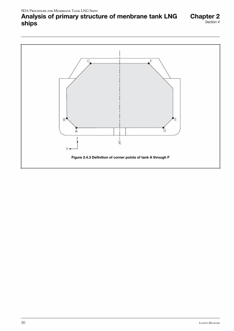
Figure 2.4.3 Definition of corner points of tank A through F
SDA Procedure for Membrane Tank LNG Ships
Analysis of primary structure of menbrane tank LNGships
Chapter 2Section 4
30 Lloyd's Register
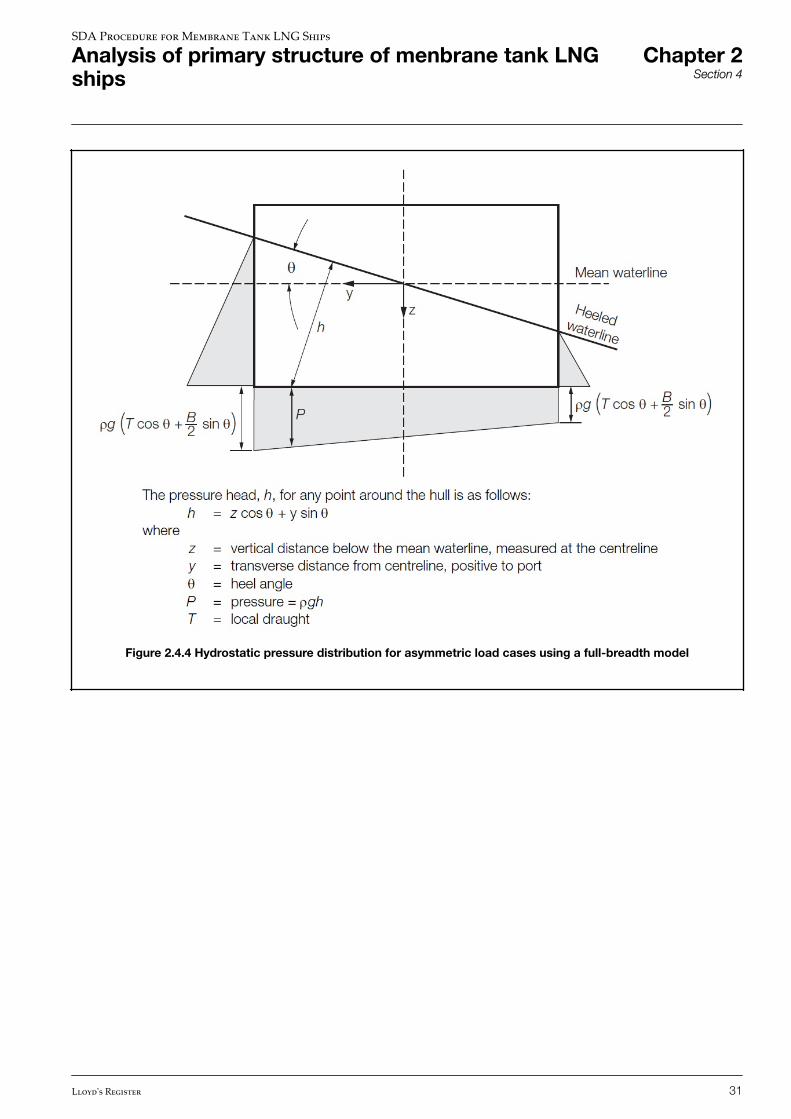
Figure 2.4.4 Hydrostatic pressure distribution for asymmetric load cases using a full-breadth model
SDA Procedure for Membrane Tank LNG Ships
Analysis of primary structure of menbrane tank LNGships
Chapter 2Section 4
Lloyd's Register 31
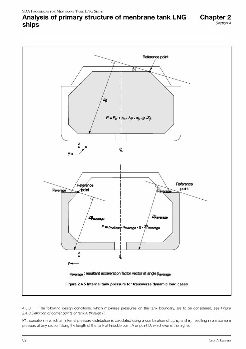
Figure 2.4.5 Internal tank pressure for transverse dynamic load cases
4.5.8 The following design conditions, which maximise pressures on the tank boundary, are to be considered, see Figure2.4.3 Definition of corner points of tank A through F:
P1: condition in which an internal pressure distribution is calculated using a combination of �x, �y and �z; resulting in a maximumpressure at any section along the length of the tank at knuckle point A or point D, whichever is the higher.
SDA Procedure for Membrane Tank LNG Ships
Analysis of primary structure of menbrane tank LNGships
Chapter 2Section 4
32 Lloyd's Register
P2: condition in which an internal pressure distribution is calculated using a combination of �x, �y and �z; resulting in a maximumpressure at any section along the length of the tank at knuckle point B or point E, whichever is the higher.
P3: condition in which an internal pressure distribution is calculated using a combination of �x, �y and �z; resulting in a maximumpressure at any section along the length of the tank at knuckle point C or point F, whichever is the higher.
4.5.9 For a tank with uniform cross section, where the maximum pressure at forward and aft sections of the tank is equal, thepoints at the forward section are to be considered. For each of these conditions, there is a specific set of values of �β and angle βto be applied to generate the maximum pressure at the point considered on the boundary of each tank, where
• �β is the resultant acceleration vector of �x, �y and �z, and
• β is the angle of the resultant acceleration vector
as shown in Figure 2.4.2 Acceleration ellipsoid.
4.5.10 The design conditions described in Ch 2, 4.5 Transverse dynamic load cases 4.5.8 are to be considered for eachloading configuration specified in Ch 2, 4.5 Transverse dynamic load cases 4.5.2.
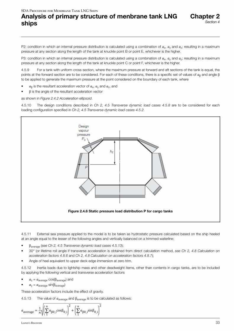
Figure 2.4.6 Static pressure load distribution P for cargo tanks
4.5.11 External sea pressure applied to the model is to be taken as hydrostatic pressure calculated based on the ship heeledat an angle equal to the lesser of the following angles and vertically balanced on a trimmed waterline:
• βaverage (see Ch 2, 4.5 Transverse dynamic load cases 4.5.13);
• 30° (or lifetime roll angle if transverse acceleration is obtained from direct calculation method, see Ch 2, 4.8 Calculation onacceleration factors 4.8.6 and Ch 2, 4.8 Calculation on acceleration factors 4.8.7);
• Angle of heel equivalent to upper deck edge immersion at zero trim.
4.5.12 Inertia loads due to lightship mass and other deadweight items, other than contents in cargo tanks, are to be includedby applying the following vertical and transverse acceleration factors
• �z = �average cos(βaverage) and
• �y = �average sin(βaverage)
These acceleration factors include the effect of gravity.
4.5.13 The value of �average and βaverage is to be calculated as follows:
�average = 1� ∑1� �β0_icosβ0_i 2+ ∑1� �β0_isinβ0_i 2
SDA Procedure for Membrane Tank LNG Ships
Analysis of primary structure of menbrane tank LNGships
Chapter 2Section 4
Lloyd's Register 33
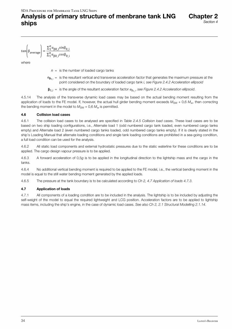
��� βaverage = ∑1��β0_i���β0_i∑1��β0_i���β0_iwhere
n = is the number of loaded cargo tanks�β0_i = is the resultant vertical and transverse acceleration factor that generates the maximum pressure at thepoint considered on the boundary of loaded cargo tank i, see Figure 2.4.2 Acceleration ellipsoid
β0_i = is the angle of the resultant acceleration factor �β0_i, see Figure 2.4.2 Acceleration ellipsoid.
4.5.14 The analysis of the transverse dynamic load cases may be based on the actual bending moment resulting from theapplication of loads to the FE model. If, however, the actual hull girder bending moment exceeds MSW + 0,6 Mw, then correctingthe bending moment in the model to MSW + 0,6 Mw is permitted.
4.6 Collision load cases
4.6.1 The collision load cases to be analysed are specified in Table 2.4.5 Collision load cases. These load cases are to bebased on two ship loading configurations, i.e., Alternate load 1 (odd numbered cargo tank loaded, even numbered cargo tanksempty) and Alternate load 2 (even numbered cargo tanks loaded, odd numbered cargo tanks empty). If it is clearly stated in theship’s Loading Manual that alternate loading conditions and single tank loading conditions are prohibited in a sea-going condition,a full load condition can be used for the analysis.
4.6.2 All static load components and external hydrostatic pressures due to the static waterline for these conditions are to beapplied. The cargo design vapour pressure is to be applied.
4.6.3 A forward acceleration of 0,5g is to be applied in the longitudinal direction to the lightship mass and the cargo in thetanks.
4.6.4 No additional vertical bending moment is required to be applied to the FE model, i.e., the vertical bending moment in themodel is equal to the still water bending moment generated by the applied loads.
4.6.5 The pressure at the tank boundary is to be calculated according to Ch 2, 4.7 Application of loads 4.7.3.
4.7 Application of loads
4.7.1 All components of a loading condition are to be included in the analysis. The lightship is to be included by adjusting theself-weight of the model to equal the required lightweight and LCG position. Acceleration factors are to be applied to lightshipmass items, including the ship’s engine, in the case of dynamic load cases. See also Ch 2, 2.1 Structural Modelling 2.1.14.
SDA Procedure for Membrane Tank LNG Ships
Analysis of primary structure of menbrane tank LNGships
Chapter 2Section 4
34 Lloyd's Register
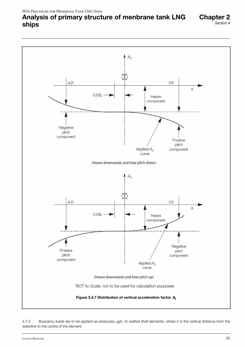
Figure 2.4.7 Distribution of vertical acceleration factor Az
4.7.2 Buoyancy loads are to be applied as pressures, ρgh, to wetted shell elements, where h is the vertical distance from thewaterline to the centre of the element.
SDA Procedure for Membrane Tank LNG Ships
Analysis of primary structure of menbrane tank LNGships
Chapter 2Section 4
Lloyd's Register 35
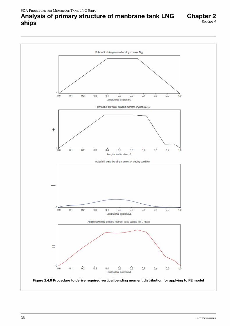
Figure 2.4.8 Procedure to derive required vertical bending moment distribution for applying to FE model
SDA Procedure for Membrane Tank LNG Ships
Analysis of primary structure of menbrane tank LNGships
Chapter 2Section 4
36 Lloyd's Register
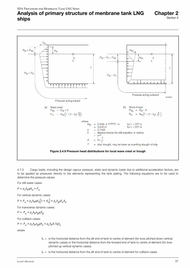
Figure 2.4.9 Pressure head distributions for local wave crest or trough
4.7.3 Cargo loads, including the design vapour pressure, static and dynamic loads due to additional acceleration factors, areto be applied as pressures directly to the elements representing the tank plating. The following equations are to be used todetermine the pressure values:
For still water cases:� = ρcΛP�ℎz+ �oFor vertical dynamic cases:� = �o+ ρcΛP�ℎz 1 + �z + ρcΛp��x�xFor transverse dynamic cases:� = �o+ ρcΛP�β��βFor collision cases:� = �o+ ρcΛP�β�ℎz+ ρcΛP0, 5��xwhere �x = is the horizontal distance from the aft end of tank to centre of element (for bow pitched down vertical
dynamic cases) or the horizontal distance from the forward end of tank to centre of element (for bowpitched up vertical dynamic cases)�x = is the horizontal distance from the aft end of tank to centre of element for collision cases
SDA Procedure for Membrane Tank LNG Ships
Analysis of primary structure of menbrane tank LNGships
Chapter 2Section 4
Lloyd's Register 37
hz = is the vertical distance from the highest point of a tank to centre of element, see Figure 2.4.6 Staticpressure load distribution P for cargo tanks�β = is the resultant acceleration factor vector (at angle β0) that generate the maximum pressure at a requiredpoint on the tank boundary, see Ch 2, 4.5 Transverse dynamic load cases 4.5.7 and Ch 2, 4.5Transverse dynamic load cases 4.5.8. The acceleration vectors required to maximise the pressure at agiven point on the tank boundary depend on tank geometry, hence they are in general different for eachcargo tank. These maximum pressures may be determined using LR’s RulesCalc software.
Zβ = is the largest liquid height above the point where the pressure is to be determined measured from thetank shell in the β direction, see Figure 2.4.5 Internal tank pressure for transverse dynamic load cases.
ΛP = ≤1,0, a factor to account for the difference in cargo tank volume measured from the primary barrier andthat measured to the ship structure.
4.7.4 Tank domes considered to be part of the accepted total tank volume shall be taken into account when determining Zβ,unless the total volume of tank domes Vd does not exceed the following value:�d = �t 100− ����where
Vt = tank volume without any domes; and
FL = filling limit in accordance with Ch 15, 15.1 of LR's Rules for Liquefied Gases.
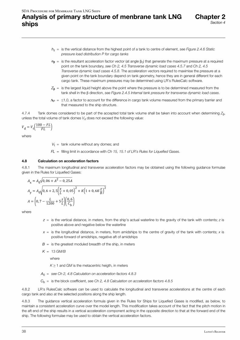
4.8 Calculation on acceleration factors
4.8.1 The maximum longitudinal and transverse acceleration factors may be obtained using the following guidance formulaegiven in the Rules for Liquefied Gases:�x = �0 0, 06 + �2− 0, 25��y = �0 0, 6 + 2, 5 �� + 0, 05 2+ � 1 + 0, 6� �� 2
� = 0, 7− �1200 + 5�� 0, 6�bwhere
z = is the vertical distance, in meters, from the ship's actual waterline to the gravity of the tank with contents; z ispositive above and negative below the waterline
x = is the longitudinal distance, in meters, from amidships to the centre of gravity of the tank with contents; x ispositive forward of amidships, negative aft of amidships
B = is the greatest moduled breadth of the ship, in meters
K = 13 GM/B
where
K ≥ 1 and GM is the metacentric heigth, in meters
A0 = see Ch 2, 4.8 Calculation on acceleration factors 4.8.3
Cb = is the block coefficient, see Ch 2, 4.8 Calculation on acceleration factors 4.8.5
4.8.2 LR's RulesCalc software can be used to calculate the longitudinal and transverse accelerations at the centre of eachcargo tank and also at the selected positions along the ship length.
4.8.3 The guidance vertical acceleration formula given in the Rules for Ships for Liquefied Gases is modified, as below, tomaintain a consistent acceleration curve over the model length. This modification takes account of the fact that the pitch motion inthe aft end of the ship results in a vertical acceleration component acting in the opposite direction to that at the forward end of theship. The following formulae may be used to obtain the vertical acceleration factors.
SDA Procedure for Membrane Tank LNG Ships
Analysis of primary structure of menbrane tank LNGships
Chapter 2Section 4
38 Lloyd's Register
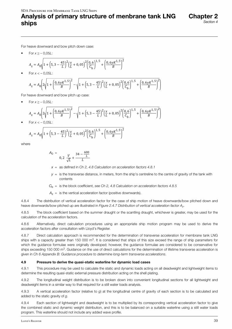
For heave downward and bow pitch down case:
• For x ≥ – 0,05L:
�z = �0 1 + 5, 3− 45� 2 �� + 0, 05 2 0, 6�b 1, 5+ 0, 6��1, 5� 2• For x < – 0,05L:
�z = �0 2 1 + 0, 6��1, 5� 2− 1 + 5, 3− 45� 2 �� + 0, 05 2 0, 6�b 1, 5+ 0, 6��1, 5� 2For heave downward and bow pitch up case:
• For x ≥ – 0,05L:
�z = �0 2 1 + 0, 6��1, 5� 2− 1 + 5, 3− 45� 2 �� + 0, 05 2 0, 6�b 1, 5+ 0, 6��1, 5� 2• For x < – 0,05L:
�z = �0 1 + 5, 3− 45� 2 �� + 0, 05 2 0, 6�b 1, 5+ 0, 6��1, 5� 2where
A0 = 0, 2 �� + 34− 600��x = as defined in Ch 2, 4.8 Calculation on acceleration factors 4.8.1
y = is the transverse distance, in meters, from the ship's centreline to the centre of gravity of the tank withcontents
Cb = is the block coefficient, see Ch 2, 4.8 Calculation on acceleration factors 4.8.5
Az = is the vertical acceleration factor (positive downwards).
4.8.4 The distribution of vertical acceleration factor for the case of ship motion of heave downwards/bow pitched down andheave downwards/bow pitched up are illustrated in Figure 2.4.7 Distribution of vertical acceleration factor Az.
4.8.5 The block coefficient based on the summer draught or the scantling draught, whichever is greater, may be used for thecalculation of the acceleration factors.
4.8.6 Alternatively, direct calculation procedures using an appropriate ship motion program may be used to derive theacceleration factors after consultation with Lloyd’s Register.
4.8.7 Direct calculation approach is recommended for the determination of transverse acceleration for membrane tank LNGships with a capacity greater than 150 000 m3. It is considered that ships of this size exceed the range of ship parameters forwhich the guidance formulae were originally developed; however, the guidance formulae are considered to be conservative forships exceeding 150 000 m3. Guidance on the use of direct calculations for the determination of lifetime transverse acceleration isgiven in Ch 6 Appendix B: Guidance procedure to determine long-term transverse accelerations.
4.9 Pressure to derive the quasi-static waterline for dynamic load cases
4.9.1 This procedure may be used to calculate the static and dynamic loads acting on all deadweight and lightweight items todetermine the resulting quasi-static external pressure distribution acting on the shell plating.
4.9.2 The longitudinal weight distribution is to be broken down into convenient longitudinal sections for all lightweight anddeadweight items in a similar way to that required for a still water loads analysis.
4.9.3 A vertical acceleration factor (relative to g) at the longitudinal centre of gravity of each section is to be calculated andadded to the static gravity of g.
4.9.4 Each section of lightweight and deadweight is to be multiplied by its corresponding vertical acceleration factor to givethe combined static and dynamic weight distribution, and this is to be balanced on a suitable waterline using a still water loadsprogram. This waterline should not include any added wave profile.
SDA Procedure for Membrane Tank LNG Ships
Analysis of primary structure of menbrane tank LNGships
Chapter 2Section 4
Lloyd's Register 39
4.9.5 The resulting quasi-static trimmed waterline is to be used to apply the external hydrostatic pressures to shell platingelements.
4.9.6 For static heel and dynamic transverse cases, the external hydrostatic pressure is to be based on the ship heeled at therequired angle and balanced vertically on a trimmed waterline. This position may be obtained by first achieving the vertical balanceof the upright ship and then the ship is heeled at the required heel angle.
4.10 Application of assigned permissible still water and design vertical wave bending moment envelope
4.10.1 Where requiredm the vertical wave bending moment and permissible vertical still water bending moment envelope are tobe applied to the FE model.
4.10.2 The additional bending moment distribution that is required to be applied to the FE model to generate the permissiblestill water and Rule design vertical wave bending moments is illustrated in Figure 2.4.8 Procedure to derive required verticalbending moment distribution for applying to FE model. This bending moment distribution takes account of the bending momentgenerated by the loading condition of the FE load case. The total bending moment, i.e. the sum of the applied additional bendingmoment and the still water bending moment from the FE load case, need not exceed the required value. Care is to be taken in thesign convention of sagging and hogging in deriving the required bending moment distribution.
4.10.3 The vertical load distribution that is required to produce the bending moment distribution can be obtained by numericaldifferentiation method. The load distribution calculated is to be approximated by a series of vertical forces acting along the lengthof the FE model. These vertical forces are to be applied as a series of nodal forces at the side shell and inner skin in proportion tothe projected vertical cross-sectional area. The distribution of the vertical forces is to be such that the required bending momentdistribution can be closely reproduced. It is recommended that the nodal forces be applied to every frame position.
4.10.4 Other proposed methods of applying the Rule vertical wave bending moment distribution and permissible vertical stillwater bending moment envelope will be specially considered.
4.11 Procedure to apply local wave crest or trough
4.11.1 For the wave load cases, an additional wave head is to be applied over the full length of the FE model using thepressure distribution shown in Ch 2, 4.7 Application of loads 4.7.2.
4.11.2 The ship’s scantling draught may be used for deriving the pressure head distribution.
n Section 5 Permissible stresses
5.1 Permissible stresses
5.1.1 The stresses resulting from the application of all load cases, with the exception of load cases O1 and O2, are not toexceed the maximum permissible values given in Table 2.5.1 Maximum permissible membrane stresses. The structural itemsindicated in Table 2.5.1 Maximum permissible membrane stresses are provided for guidance as to the most likely critical areas. Allstresses for all parts of the model are to be examined.
5.1.2 The maximum permissible stresses applicable for load cases O1 and O2, the collision cases, are given in Table 2.5.2Maximum permissible membrane stresses (collision load cases).
5.1.3 In addition, it should be noted that the longitudinal hull girder elements should comply, as a minimum, with therequirements in Pt 3, Ch 4 of the Rules for Ships, see Ch 1, 1.1 Introduction 1.1.4.
5.1.4 The permissible stress criteria in Table 2.5.1 Maximum permissible membrane stresses and Table 2.5.2 Maximumpermissible membrane stresses (collision load cases) are based on the recommended mesh size indicated in Ch 2, 2 Structuralmodelling.
5.1.5 In addition to the criteria given in Table 2.5.1 Maximum permissible membrane stresses, design requirements imposedby the containment system manufacturer are to be complied with, see Ch 1, 1.1 Introduction 1.1.4.
SDA Procedure for Membrane Tank LNG Ships
Analysis of primary structure of menbrane tank LNGships
Chapter 2Section 5
40 Lloyd's Register
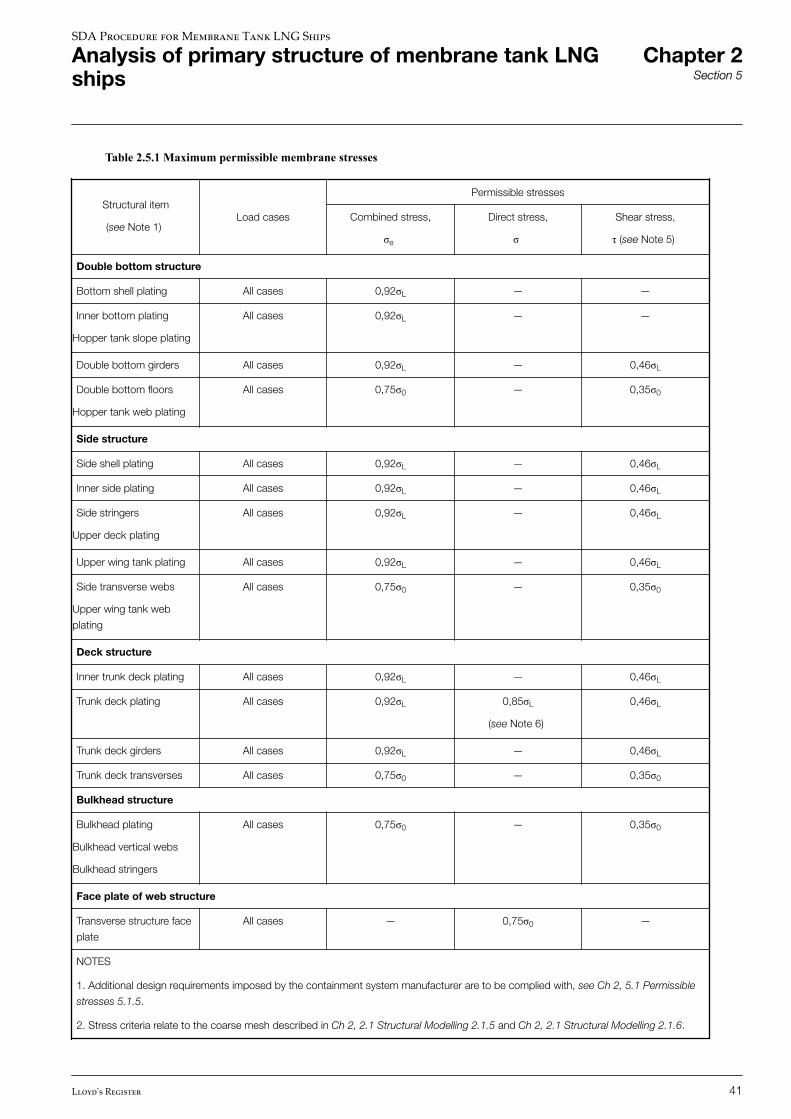
Table 2.5.1 Maximum permissible membrane stresses
Structural item
(see Note 1)Load cases
Permissible stresses
Combined stress,
σe
Direct stress,
σ
Shear stress,
τ (see Note 5)
Double bottom structure
Bottom shell plating All cases 0,92σL — —
Inner bottom plating
Hopper tank slope plating
All cases 0,92σL — —
Double bottom girders All cases 0,92σL — 0,46σL
Double bottom floors
Hopper tank web plating
All cases 0,75σ0 — 0,35σ0
Side structure
Side shell plating All cases 0,92σL — 0,46σL
Inner side plating All cases 0,92σL — 0,46σL
Side stringers
Upper deck plating
All cases 0,92σL — 0,46σL
Upper wing tank plating All cases 0,92σL — 0,46σL
Side transverse webs
Upper wing tank web
plating
All cases 0,75σ0 — 0,35σ0
Deck structure
Inner trunk deck plating All cases 0,92σL — 0,46σL
Trunk deck plating All cases 0,92σL 0,85σL
(see Note 6)
0,46σL
Trunk deck girders All cases 0,92σL — 0,46σL
Trunk deck transverses All cases 0,75σ0 — 0,35σ0
Bulkhead structure
Bulkhead plating
Bulkhead vertical webs
Bulkhead stringers
All cases 0,75σ0 — 0,35σ0
Face plate of web structure
Transverse structure face
plate
All cases — 0,75σ0 —
NOTES
1. Additional design requirements imposed by the containment system manufacturer are to be complied with, see Ch 2, 5.1 Permissible
stresses 5.1.5.
2. Stress criteria relate to the coarse mesh described in Ch 2, 2.1 Structural Modelling 2.1.5 and Ch 2, 2.1 Structural Modelling 2.1.6.
SDA Procedure for Membrane Tank LNG Ships
Analysis of primary structure of menbrane tank LNGships
Chapter 2Section 5
Lloyd's Register 41
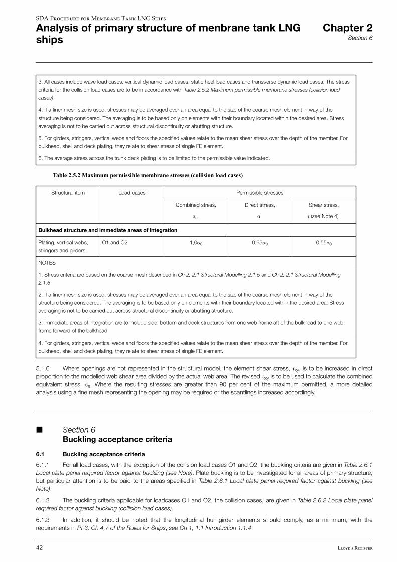
3. All cases include wave load cases, vertical dynamic load cases, static heel load cases and transverse dynamic load cases. The stress
criteria for the collision load cases are to be in accordance with Table 2.5.2 Maximum permissible membrane stresses (collision load
cases).
4. If a finer mesh size is used, stresses may be averaged over an area equal to the size of the coarse mesh element in way of the
structure being considered. The averaging is to be based only on elements with their boundary located within the desired area. Stress
averaging is not to be carried out across structural discontinuity or abutting structure.
5. For girders, stringers, vertical webs and floors the specified values relate to the mean shear stress over the depth of the member. For
bulkhead, shell and deck plating, they relate to shear stress of single FE element.
6. The average stress across the trunk deck plating is to be limited to the permissible value indicated.
Table 2.5.2 Maximum permissible membrane stresses (collision load cases)
Structural item Load cases Permissible stresses
Combined stress,
σe
Direct stress,
σ
Shear stress,
τ (see Note 4)
Bulkhead structure and immediate areas of integration
Plating, vertical webs,
stringers and girders
O1 and O2 1,0σ0 0,95σ0 0,55σ0
NOTES
1. Stress criteria are based on the coarse mesh described in Ch 2, 2.1 Structural Modelling 2.1.5 and Ch 2, 2.1 Structural Modelling
2.1.6.
2. If a finer mesh size is used, stresses may be averaged over an area equal to the size of the coarse mesh element in way of the
structure being considered. The averaging is to be based only on elements with their boundary located within the desired area. Stress
averaging is not to be carried out across structural discontinuity or abutting structure.
3. Immediate areas of integration are to include side, bottom and deck structures from one web frame aft of the bulkhead to one web
frame forward of the bulkhead.
4. For girders, stringers, vertical webs and floors the specified values relate to the mean shear stress over the depth of the member. For
bulkhead, shell and deck plating, they relate to shear stress of single FE element.
5.1.6 Where openings are not represented in the structural model, the element shear stress, τxy, is to be increased in directproportion to the modelled web shear area divided by the actual web area. The revised τxy is to be used to calculate the combinedequivalent stress, σe. Where the resulting stresses are greater than 90 per cent of the maximum permitted, a more detailedanalysis using a fine mesh representing the opening may be required or the scantlings increased accordingly.
n Section 6 Buckling acceptance criteria
6.1 Buckling acceptance criteria
6.1.1 For all load cases, with the exception of the collision load cases O1 and O2, the buckling criteria are given in Table 2.6.1Local plate panel required factor against buckling (see Note). Plate buckling is to be investigated for all areas of primary structure,but particular attention is to be paid to the areas specified in Table 2.6.1 Local plate panel required factor against buckling (seeNote).
6.1.2 The buckling criteria applicable for loadcases O1 and O2, the collision cases, are given in Table 2.6.2 Local plate panelrequired factor against buckling (collision load cases).
6.1.3 In addition, it should be noted that the longitudinal hull girder elements should comply, as a minimum, with therequirements in Pt 3, Ch 4,7 of the Rules for Ships, see Ch 1, 1.1 Introduction 1.1.4.
SDA Procedure for Membrane Tank LNG Ships
Analysis of primary structure of menbrane tank LNGships
Chapter 2Section 6
42 Lloyd's Register
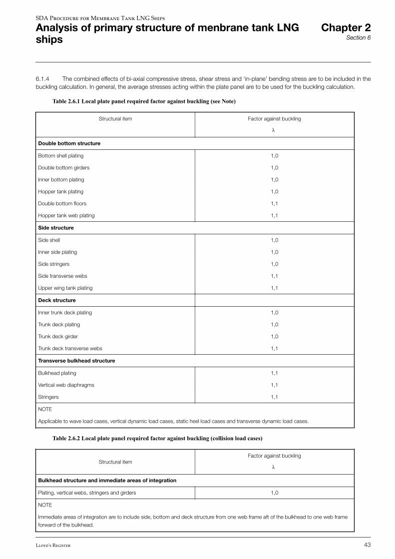
6.1.4 The combined effects of bi-axial compressive stress, shear stress and ‘in-plane’ bending stress are to be included in thebuckling calculation. In general, the average stresses acting within the plate panel are to be used for the buckling calculation.
Table 2.6.1 Local plate panel required factor against buckling (see Note)
Structural item Factor against buckling
λ
Double bottom structure
Bottom shell plating 1,0
Double bottom girders 1,0
Inner bottom plating 1,0
Hopper tank plating 1,0
Double bottom floors 1,1
Hopper tank web plating 1,1
Side structure
Side shell 1,0
Inner side plating 1,0
Side stringers 1,0
Side transverse webs 1,1
Upper wing tank plating 1,1
Deck structure
Inner trunk deck plating 1,0
Trunk deck plating 1,0
Trunk deck girder 1,0
Trunk deck transverse webs 1,1
Transverse bulkhead structure
Bulkhead plating 1,1
Vertical web diaphragms 1,1
Stringers 1,1
NOTE
Applicable to wave load cases, vertical dynamic load cases, static heel load cases and transverse dynamic load cases.
Table 2.6.2 Local plate panel required factor against buckling (collision load cases)
Structural itemFactor against buckling
λ
Bulkhead structure and immediate areas of integration
Plating, vertical webs, stringers and girders 1,0
NOTE
Immediate areas of integration are to include side, bottom and deck structure from one web frame aft of the bulkhead to one web frame
forward of the bulkhead.
SDA Procedure for Membrane Tank LNG Ships
Analysis of primary structure of menbrane tank LNGships
Chapter 2Section 6
Lloyd's Register 43
6.1.5 Panel buckling calculations are to be based on the proposed thickness of the plating reduced by a thickness deductionfor corrosion. A corrosion deduction of 1 mm is to be made for all structural items for each surface in contact with ballast water.No deduction is to be made for other surfaces.
6.1.6 In general, the applied stresses for buckling assessment are to be increased by a factor equal to the original thicknessdivided by the thickness after corrosion.
6.1.7 For the direct stress component which includes hull girder bending stress, it is permissible to adjust only the local stresscomponent by the corrosion deduction. All other stress components are to be applied in accordance with Ch 2, 6.1 Bucklingacceptance criteria 6.1.6.
6.1.8 In calculating the factors against buckling, the edge restraint factor ‘c’ defined in Pt 3, Ch 4,7 of the Rules for Ships maybe taken into account in calculating the critical buckling stress of wide panels subjected to compressive loading on the long edgeof the panel. The edge restraint factor ‘c’ is not to be used in the calculation of the critical buckling stress for compression appliedon the short edges.
6.1.9 When the calculated elastic critical buckling stress, σc, exceeds 50 per cent of the specified minimum yield stress, thenthe buckling stress is to be adjusted for the effects of plasticity using the Johnson-Ostenfeld correction formula, given below:
• when σc ≤ 0,5 σoσcr = σc• when σc > 0,5 σoσcr = σc 1− σo4σcwhere
σcr = critical buckling stress corrected for plasticity effects σc, σo, see Ch 1, 2 Symbols.
n Section 7 Primary member deflections
7.1 Primary memeber deflections
7.1.1 It should be ascertained that the deflections of primary members including angular deflections (i.e., relative deflectionbetween joining primary members and deflections of secondary structural members relative to primary structure) are compatiblewith the containment system. The requirements or guidance of the containment system designer should be followed in this matter.
SDA Procedure for Membrane Tank LNG Ships
Analysis of primary structure of menbrane tank LNGships
Chapter 2Section 7
44 Lloyd's Register
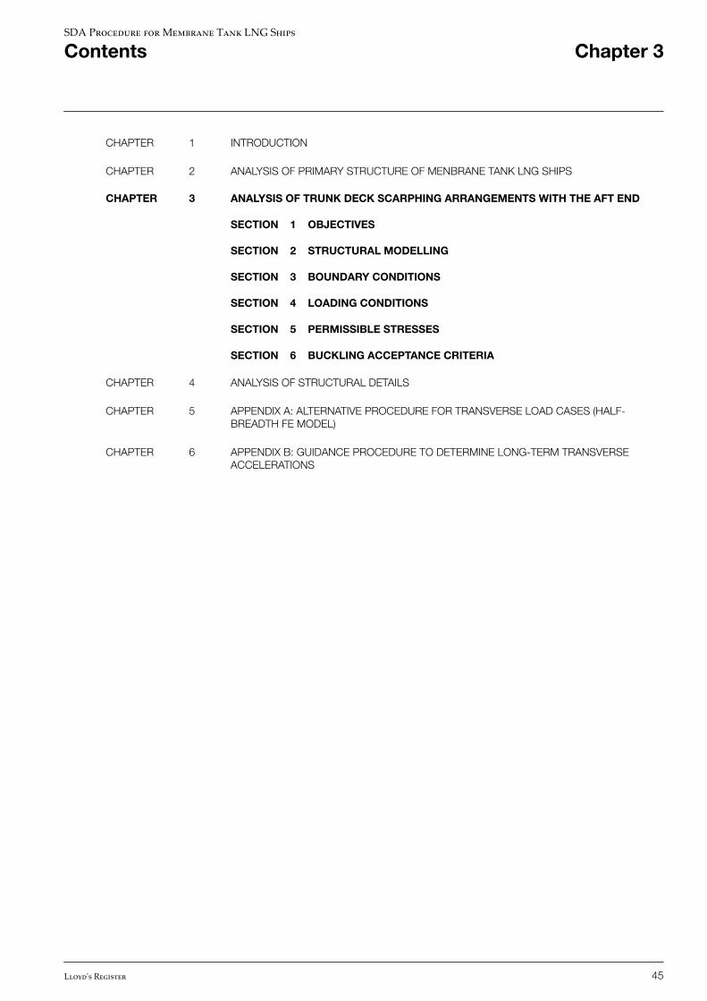
CHAPTER 1 INTRODUCTION
CHAPTER 2 ANALYSIS OF PRIMARY STRUCTURE OF MENBRANE TANK LNG SHIPS
CHAPTER 3 ANALYSIS OF TRUNK DECK SCARPHING ARRANGEMENTS WITH THE AFT END
SECTION 1 OBJECTIVES
SECTION 2 STRUCTURAL MODELLING
SECTION 3 BOUNDARY CONDITIONS
SECTION 4 LOADING CONDITIONS
SECTION 5 PERMISSIBLE STRESSES
SECTION 6 BUCKLING ACCEPTANCE CRITERIA
CHAPTER 4 ANALYSIS OF STRUCTURAL DETAILS
CHAPTER 5 APPENDIX A: ALTERNATIVE PROCEDURE FOR TRANSVERSE LOAD CASES (HALF-BREADTH FE MODEL)
CHAPTER 6 APPENDIX B: GUIDANCE PROCEDURE TO DETERMINE LONG-TERM TRANSVERSEACCELERATIONS
SDA Procedure for Membrane Tank LNG Ships
Contents Chapter 3
Lloyd's Register 45
Section1 Objectives
2 Structural modelling
3 Boundary conditions
4 Loading conditions
5 Permissible stresses
6 Buckling acceptance criteria
n Section 1 Objectives
1.1 Objectives
1.1.1 The objective of this Chapter of this SDA procedure is to ensure that the structural arrangement of the transition fromthe cargo tank region to the aft end structure is satisfactory.
1.1.2 In particular, this analysis is to enable the distribution of loads from the trunk deck structure into the deckhouse andmain deck structure at the aft end to be accurately modelled.
1.1.3 The analysis is to be sufficient to enable the effect of all critical openings and structural discontinuities (i.e., doors,windows, access openings, end of trunk deck and scarphing brackets, etc.) to be determined.
1.1.4 The structural analysis described in this Chapter is not to be used to verify the minimum required scantlings of the aftpart of aftmost cargo tank including its aftmost bulkhead. These areas are to be verified using the analysis specified in Ch 2Analysis of primary structure of menbrane tank LNG ships.
IMPORTANT NOTE
The objective of this procedure is to assess the strength of the ship primary structure to withstand the design loads. The ability ofthe containment system to accommodate the global or local deformations of the ship structure is not considered in this procedure.Therefore it is necessary for the designers to consider and demonstrate separately that the containment system design in terms ofstrength and fatigue capability can withstand the global and local deformations of the ship structure. Additional designrequirements with respect to the ship structure specified by the containment system supplier are to be complied with. It isrecommended that the designer consult the containment system supplier early on in the design cycle.
n Section 2 Structural modelling
2.1 Structural modelling
2.1.1 The 3-D finite element model of the aft end is to extend from the transom to the middle of the aft cargo hold. The modelis to include all primary structure.
2.1.2 The model is to include the deckhouses and all internal structure, especially where the internal structure will form part ofthe load path from the trunk decks to the main deck. Similarly, in cases where the longitudinal bulkheads of the cargo region arenot continuous through the engine room, the scarphing arrangements of the longitudinal bulkheads are to be adequatelyrepresented in the model.
2.1.3 If structural symmetry about the ship's centreline exists then a half-breadth model may be used.
2.1.4 The model of this area developed for the Ch 2 Analysis of primary structure of menbrane tank LNG ships analysis maybe used for this investigation, provided that it complies with the meshing arrangements described in this Chapter.
SDA Procedure for Membrane Tank LNG Ships
Analysis of trunk deck scarphing arrangements withthe aft end
Chapter 3Section 1
46 Lloyd's Register
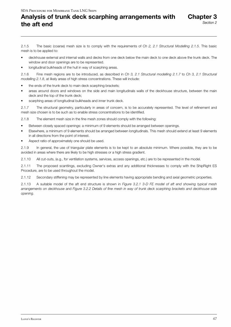
2.1.5 The basic (coarse) mesh size is to comply with the requirements of Ch 2, 2.1 Structural Modelling 2.1.5. This basicmesh is to be applied to:
• deckhouse external and internal walls and decks from one deck below the main deck to one deck above the trunk deck. Thewindow and door openings are to be represented.
• longitudinal bulkheads of the hull in way of scarphing areas.
2.1.6 Fine mesh regions are to be introduced, as described in Ch 3, 2.1 Structural modelling 2.1.7 to Ch 3, 2.1 Structuralmodelling 2.1.8, at likely areas of high stress concentrations. These will include:
• the ends of the trunk deck to main deck scarphing brackets;
• areas around doors and windows on the side and main longitudinals walls of the deckhouse structure, between the maindeck and the top of the trunk deck;
• scarphing areas of longitudinal bulkheads and inner trunk deck.
2.1.7 The structural geometry, particularly in areas of concern, is to be accurately represented. The level of refinement andmesh size chosen is to be such as to enable stress concentrations to be identified.
2.1.8 The element mesh size in the fine mesh zones should comply with the following:
• Between closely spaced openings: a minimum of 9 elements should be arranged between openings.
• Elsewhere, a minimum of 9 elements should be arranged between longitudinals. This mesh should extend at least 9 elementsin all directions from the point of interest.
• Aspect ratio of approximately one should be used.
2.1.9 In general, the use of triangular plate elements is to be kept to an absolute minimum. Where possible, they are to beavoided in areas where there are likely to be high stresses or a high stress gradient.
2.1.10 All cut-outs, (e.g., for ventilation systems, services, access openings, etc.) are to be represented in the model.
2.1.11 The proposed scantlings, excluding Owner's extras and any additional thicknesses to comply with the ShipRight ESProcedure, are to be used throughout the model.
2.1.12 Secondary stiffening may be represented by line elements having appropriate bending and axial geometric properties.
2.1.13 A suitable model of the aft end structure is shown in Figure 3.2.1 3-D FE model of aft end showing typical mesharrangements on deckhouse and Figure 3.2.2 Details of fine mesh in way of trunk deck scarphing brackets and deckhouse sideopening.
SDA Procedure for Membrane Tank LNG Ships
Analysis of trunk deck scarphing arrangements withthe aft end
Chapter 3Section 2
Lloyd's Register 47
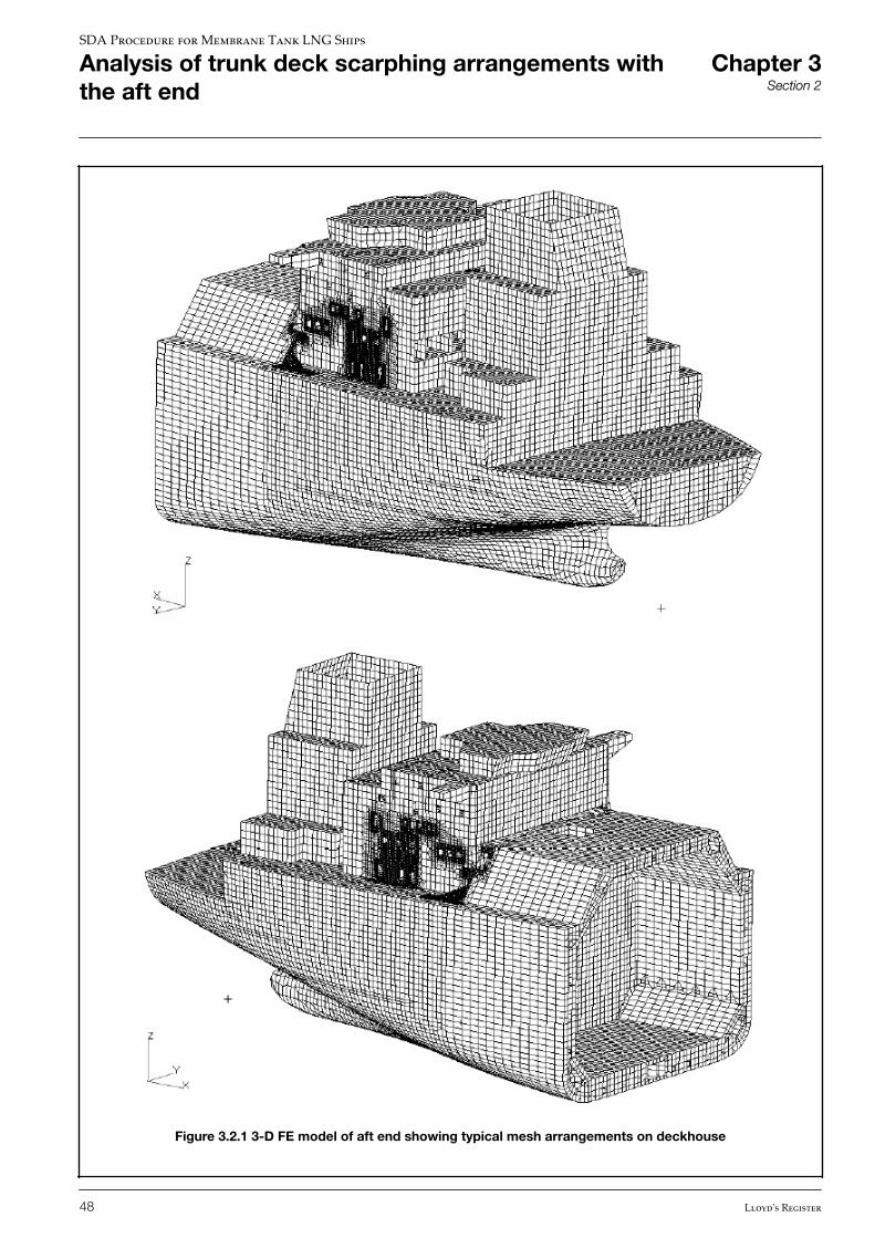
Figure 3.2.1 3-D FE model of aft end showing typical mesh arrangements on deckhouse
SDA Procedure for Membrane Tank LNG Ships
Analysis of trunk deck scarphing arrangements withthe aft end
Chapter 3Section 2
48 Lloyd's Register
Figure 3.2.2 Details of fine mesh in way of trunk deck scarphing brackets and deckhouse side opening
n Section 3 Boundary conditions
3.1 Boundary conditions
3.1.1 The grid points of all longitudinal elements at the model end section in way of the middle of the aft cargo hold are to beto be constrained in δx, δy, δz, θx, θy and θz degrees of freedom.
When using a half-breadth model, symmetry constraint, i.e., δy = 0, θx = 0 and θz= 0, is to be applied to all nodes on thecentreline.
SDA Procedure for Membrane Tank LNG Ships
Analysis of trunk deck scarphing arrangements withthe aft end
Chapter 3Section 3
Lloyd's Register 49
n Section 4 Loading conditions
4.1 Loading conditions
4.1.1 Two load cases are required to be considered for the aft end model. These load cases relate to the application of thefollowing bending moments and shear forces to the aft end model:
Case 1
Combined permissible hogging still water plus design hogging wave bending moment and combined Rule positive permissible stillwater plus design positive wave shear force, see Pt 3, Ch 4,5 and Ch 4,6 of the Rules for Ships.
Case 2
Combined permissible sagging still water plus design wave sagging bending moment and combined Rule negative permissible stillwater plus design negative wave shear force, see Pt 3, Ch 4,5 and Ch 4,6 of the Rules for Ships.
4.1.2 The permissible hogging and permissible sagging still water bending moments are to be taken as the maximum hoggingand sagging MSW of all loaded and ballast conditions, see Ch 2, 4.1 Introduction 4.1.5.
4.1.3 The values of the combined still water plus wave bending moment and the combined still water plus wave shear forceare to be derived for the longitudinal location where the trunk deck terminates.
4.1.4 A vertical force equal to the shear force is to be applied at the aft end of the model so that the required bending momentis generated at the longitudinal location where the trunk deck terminates, see Figure 3.4.1 Shear force applied to aft end FEmodel.
4.1.5 The vertical force is to be applied as a series of nodal forces at the side shell in proportion to the projected verticalcross-sectional plate area.
4.1.6 The model may be considered weightless and no other load components are to be applied to the model.
SDA Procedure for Membrane Tank LNG Ships
Analysis of trunk deck scarphing arrangements withthe aft end
Chapter 3Section 4
50 Lloyd's Register
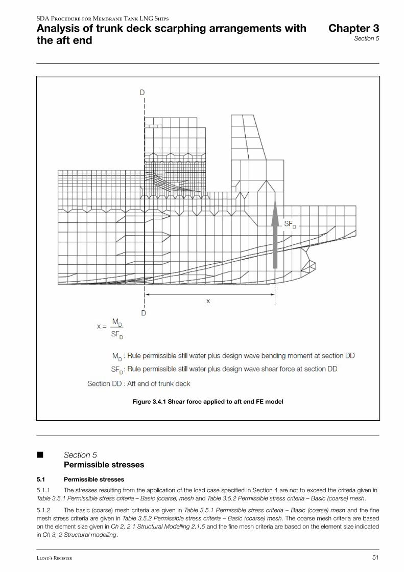
Figure 3.4.1 Shear force applied to aft end FE model
n Section 5 Permissible stresses
5.1 Permissible stresses
5.1.1 The stresses resulting from the application of the load case specified in Section 4 are not to exceed the criteria given in Table 3.5.1 Permissible stress criteria – Basic (coarse) mesh and Table 3.5.2 Permissible stress criteria – Basic (coarse) mesh.
5.1.2 The basic (coarse) mesh criteria are given in Table 3.5.1 Permissible stress criteria – Basic (coarse) mesh and the finemesh stress criteria are given in Table 3.5.2 Permissible stress criteria – Basic (coarse) mesh. The coarse mesh criteria are basedon the element size given in Ch 2, 2.1 Structural Modelling 2.1.5 and the fine mesh criteria are based on the element size indicatedin Ch 3, 2 Structural modelling.
SDA Procedure for Membrane Tank LNG Ships
Analysis of trunk deck scarphing arrangements withthe aft end
Chapter 3Section 5
Lloyd's Register 51
5.1.3 The shear stress at any longitudinal position may be corrected by the ratio of the required shear force at that position,based on the Rule combined permissible still water plus design wave shear force distribution, to the applied shear force. Thecombined stress may be recalculated using the corrected shear stress prior to comparison with the permissible stress values.
Table 3.5.1 Permissible stress criteria – Basic (coarse) mesh
Structural item Permissible stresses
von Mises stress
Single element criteria for elements clear of
the fine mesh regions
Longitudinal material 0,80σL
See Note Transverse material 0,80σo
NOTE
Criteria for the fine mesh regions are given in Table 3.5.2 Permissible stress criteria – Basic (coarse) mesh.
Table 3.5.2 Permissible stress criteria – Basic (coarse) mesh
Load case Location Stress criterion Allowable stress
Combined still water and wave,
see Ch 3, 4.1 Loading
conditions 4.1.1
Between openings Average Von Mises stress
between openings
0,94σo (see Note 2)
Average shear stress between
openings
0,47σo (see Note 2)
Scarphing brackets, corners of
openings and other structural
details
Average Von Mises stress 1,0σo (see Note 1)
Average shear stress 0,47σo (see Note 1)
Individual element Von Mises
stress
1,2σo
NOTES:
1. The average stress from the element being assessed and the elements directly connected to its boundary nodes. Averaging is not to
be taken across or include abutting structural boundaries, discontinuities or members.
2. Average stress is to be calculated independently of the sign of the individual stress levels.
n Section 6 Buckling acceptance criteria
6.1 Buckling acceptance criteria
6.1.1 A buckling assessment is to be carried out for aft end analysis in accordance with Ch 2, 6 Buckling acceptance criteria.
A factor against buckling, λ, of 1,0 is to be achieved for all areas of the structure.
SDA Procedure for Membrane Tank LNG Ships
Analysis of trunk deck scarphing arrangements withthe aft end
Chapter 3Section 6
52 Lloyd's Register
CHAPTER 1 INTRODUCTION
CHAPTER 2 ANALYSIS OF PRIMARY STRUCTURE OF MENBRANE TANK LNG SHIPS
CHAPTER 3 ANALYSIS OF TRUNK DECK SCARPHING ARRANGEMENTS WITH THE AFT END
CHAPTER 4 ANALYSIS OF STRUCTURAL DETAILS
SECTION 1 OBJECTIVES
SECTION 2 STRUCTURAL MODELLING
SECTION 3 LOADING AND BOUNDARY CONDITIONS
SECTION 4 PERMISSIBLE STRESSES
CHAPTER 5 APPENDIX A: ALTERNATIVE PROCEDURE FOR TRANSVERSE LOAD CASES (HALF-BREADTH FE MODEL)
CHAPTER 6 APPENDIX B: GUIDANCE PROCEDURE TO DETERMINE LONG-TERM TRANSVERSEACCELERATIONS
SDA Procedure for Membrane Tank LNG Ships
Contents Chapter 4
Lloyd's Register 53
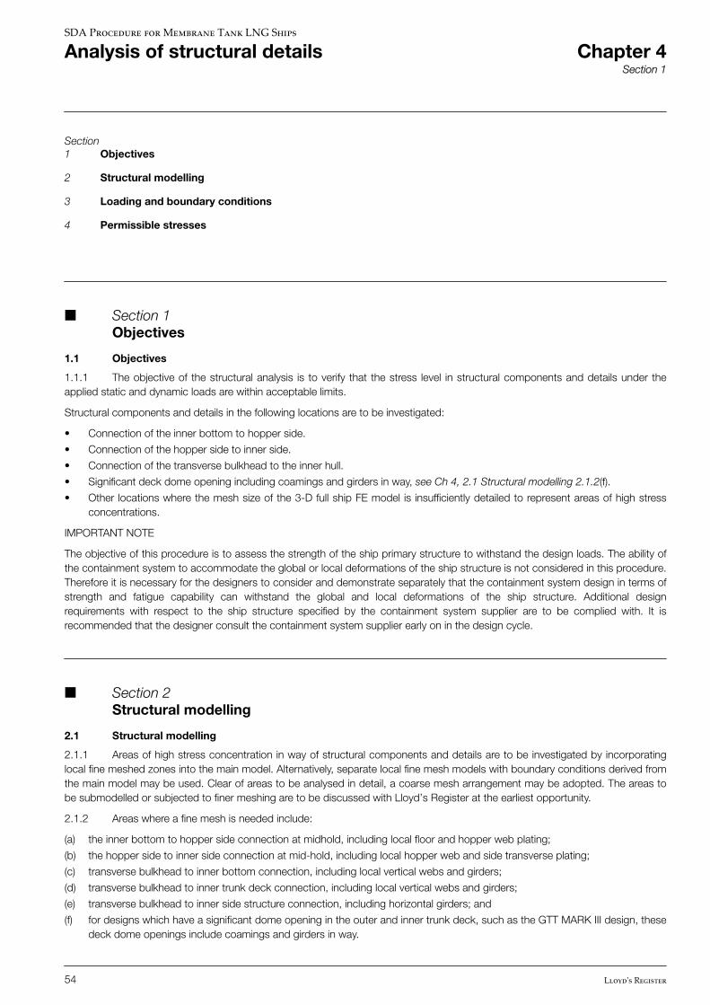
Section1 Objectives
2 Structural modelling
3 Loading and boundary conditions
4 Permissible stresses
n Section 1 Objectives
1.1 Objectives
1.1.1 The objective of the structural analysis is to verify that the stress level in structural components and details under theapplied static and dynamic loads are within acceptable limits.
Structural components and details in the following locations are to be investigated:
• Connection of the inner bottom to hopper side.
• Connection of the hopper side to inner side.
• Connection of the transverse bulkhead to the inner hull.
• Significant deck dome opening including coamings and girders in way, see Ch 4, 2.1 Structural modelling 2.1.2(f).
• Other locations where the mesh size of the 3-D full ship FE model is insufficiently detailed to represent areas of high stressconcentrations.
IMPORTANT NOTE
The objective of this procedure is to assess the strength of the ship primary structure to withstand the design loads. The ability ofthe containment system to accommodate the global or local deformations of the ship structure is not considered in this procedure.Therefore it is necessary for the designers to consider and demonstrate separately that the containment system design in terms ofstrength and fatigue capability can withstand the global and local deformations of the ship structure. Additional designrequirements with respect to the ship structure specified by the containment system supplier are to be complied with. It isrecommended that the designer consult the containment system supplier early on in the design cycle.
n Section 2 Structural modelling
2.1 Structural modelling
2.1.1 Areas of high stress concentration in way of structural components and details are to be investigated by incorporatinglocal fine meshed zones into the main model. Alternatively, separate local fine mesh models with boundary conditions derived fromthe main model may be used. Clear of areas to be analysed in detail, a coarse mesh arrangement may be adopted. The areas tobe submodelled or subjected to finer meshing are to be discussed with Lloyd’s Register at the earliest opportunity.
2.1.2 Areas where a fine mesh is needed include:
(a) the inner bottom to hopper side connection at midhold, including local floor and hopper web plating;
(b) the hopper side to inner side connection at mid-hold, including local hopper web and side transverse plating;
(c) transverse bulkhead to inner bottom connection, including local vertical webs and girders;
(d) transverse bulkhead to inner trunk deck connection, including local vertical webs and girders;
(e) transverse bulkhead to inner side structure connection, including horizontal girders; and
(f) for designs which have a significant dome opening in the outer and inner trunk deck, such as the GTT MARK III design, thesedeck dome openings include coamings and girders in way.
SDA Procedure for Membrane Tank LNG Ships
Analysis of structural details Chapter 4Section 1
54 Lloyd's Register
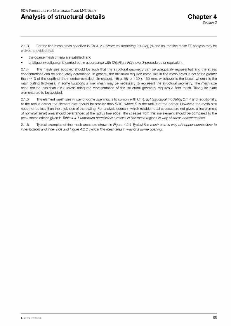
2.1.3 For the fine mesh areas specified in Ch 4, 2.1 Structural modelling 2.1.2(c), (d) and (e), the fine mesh FE analysis may bewaived, provided that:
• the coarse mesh criteria are satisfied; and
• a fatigue investigation is carried out in accordance with ShipRight FDA level 3 procedures or equivalent.
2.1.4 The mesh size adopted should be such that the structural geometry can be adequately represented and the stressconcentrations can be adequately determined. In general, the minimum required mesh size in fine mesh areas is not to be greaterthan 1/10 of the depth of the member (smallest dimension), 15t x 15t or 150 x 150 mm, whichever is the lesser, where t is themain plating thickness. In some locations a finer mesh may be necessary to represent the structural geometry. The mesh sizeneed not be less than t x t unless adequate representation of the structural geometry requires a finer mesh. Triangular plateelements are to be avoided.
2.1.5 The element mesh size in way of dome openings is to comply with Ch 4, 2.1 Structural modelling 2.1.4 and, additionally,at the radius corner the element size should be smaller than R/10, where R is the radius of the corner. However, the mesh sizeneed not be less than the thickness of the plating. For analysis codes in which reliable nodal stresses are not given, a line elementof nominal (small) area should be arranged at the radius free edge. The stresses from this line element should be compared to thepeak stress criteria given in Table 4.4.1 Maximum permissible stresses in fine mesh regions in way of stress concentrations.
2.1.6 Typical examples of fine mesh areas are shown in Figure 4.2.1 Typical fine mesh area in way of hopper connections toinner bottom and inner side and Figure 4.2.2 Typical fine mesh area in way of a dome opening.
SDA Procedure for Membrane Tank LNG Ships
Analysis of structural details Chapter 4Section 2
Lloyd's Register 55
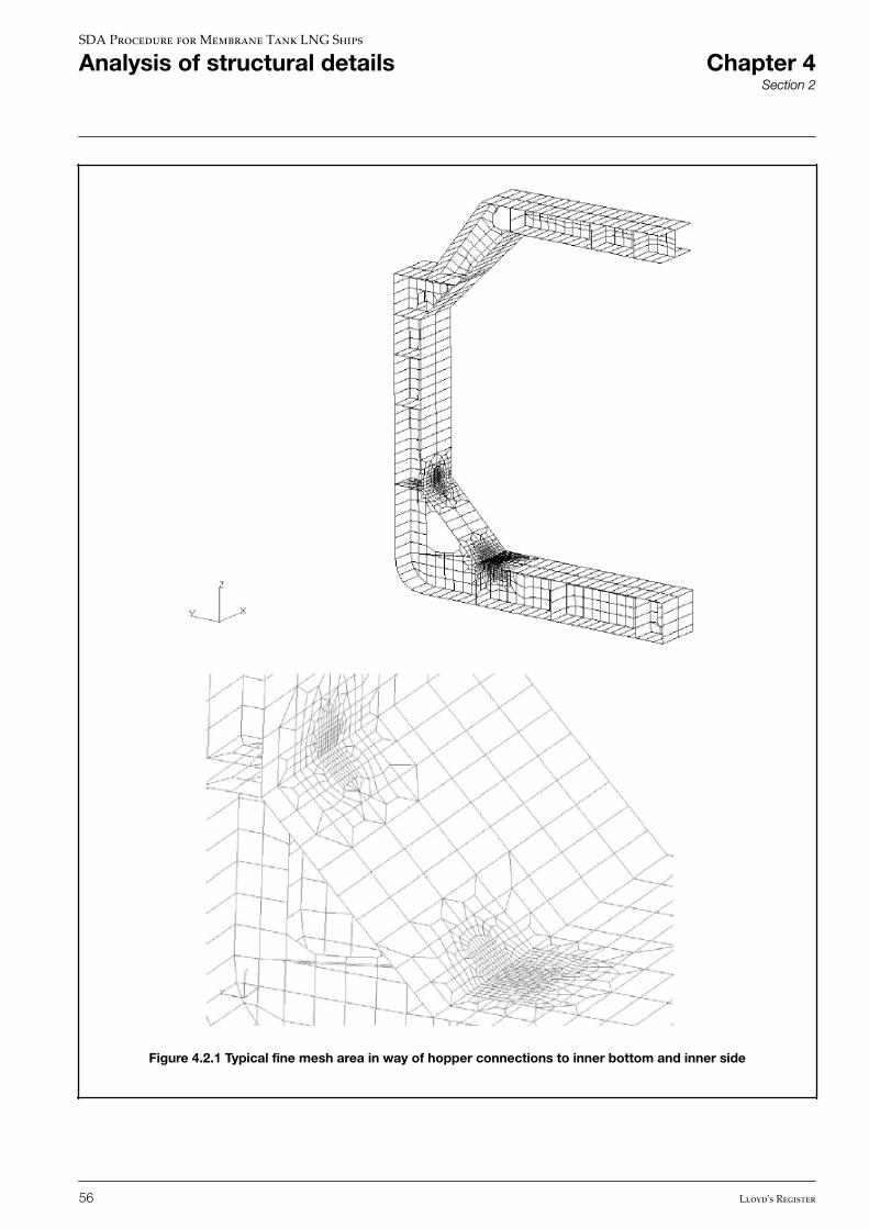
Figure 4.2.1 Typical fine mesh area in way of hopper connections to inner bottom and inner side
SDA Procedure for Membrane Tank LNG Ships
Analysis of structural details Chapter 4Section 2
56 Lloyd's Register
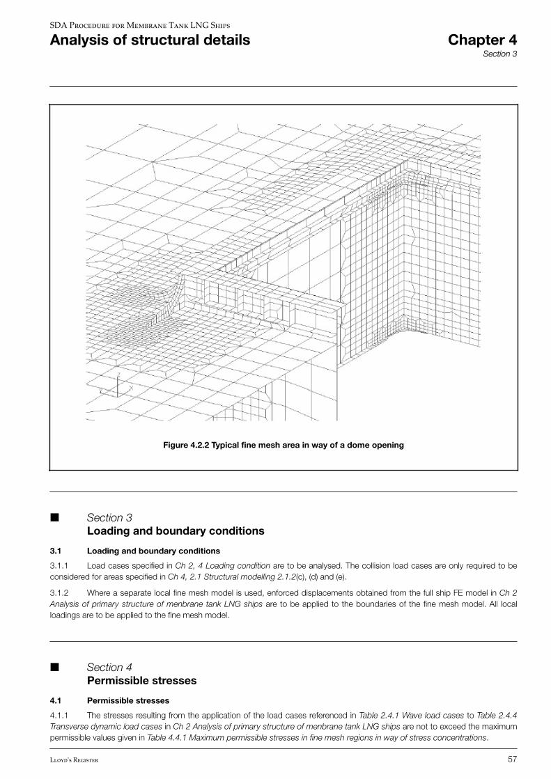
Figure 4.2.2 Typical fine mesh area in way of a dome opening
n Section 3 Loading and boundary conditions
3.1 Loading and boundary conditions
3.1.1 Load cases specified in Ch 2, 4 Loading condition are to be analysed. The collision load cases are only required to beconsidered for areas specified in Ch 4, 2.1 Structural modelling 2.1.2(c), (d) and (e).
3.1.2 Where a separate local fine mesh model is used, enforced displacements obtained from the full ship FE model in Ch 2Analysis of primary structure of menbrane tank LNG ships are to be applied to the boundaries of the fine mesh model. All localloadings are to be applied to the fine mesh model.
n Section 4 Permissible stresses
4.1 Permissible stresses
4.1.1 The stresses resulting from the application of the load cases referenced in Table 2.4.1 Wave load cases to Table 2.4.4Transverse dynamic load cases in Ch 2 Analysis of primary structure of menbrane tank LNG ships are not to exceed the maximumpermissible values given in Table 4.4.1 Maximum permissible stresses in fine mesh regions in way of stress concentrations.
SDA Procedure for Membrane Tank LNG Ships
Analysis of structural details Chapter 4Section 3
Lloyd's Register 57
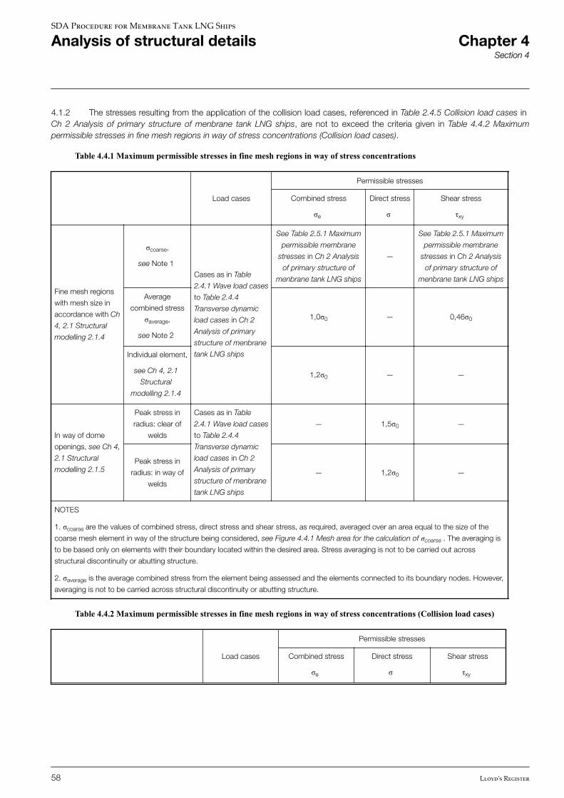
4.1.2 The stresses resulting from the application of the collision load cases, referenced in Table 2.4.5 Collision load cases in Ch 2 Analysis of primary structure of menbrane tank LNG ships, are not to exceed the criteria given in Table 4.4.2 Maximumpermissible stresses in fine mesh regions in way of stress concentrations (Collision load cases).
Table 4.4.1 Maximum permissible stresses in fine mesh regions in way of stress concentrations
Load cases
Permissible stresses
Combined stress
σe
Direct stress
σ
Shear stress
τxy
Fine mesh regions
with mesh size in
accordance with Ch
4, 2.1 Structural
modelling 2.1.4
σcoarse,
see Note 1Cases as in Table
2.4.1 Wave load cases
to Table 2.4.4
Transverse dynamic
load cases in Ch 2
Analysis of primary
structure of menbrane
tank LNG ships
See Table 2.5.1 Maximum
permissible membrane
stresses in Ch 2 Analysis
of primary structure of
menbrane tank LNG ships
—
See Table 2.5.1 Maximum
permissible membrane
stresses in Ch 2 Analysis
of primary structure of
menbrane tank LNG ships
Average
combined stress
σaverage,
see Note 2
1,0σ0 — 0,46σ0
Individual element,
see Ch 4, 2.1
Structural
modelling 2.1.4
1,2σ0 — —
In way of dome
openings, see Ch 4,
2.1 Structural
modelling 2.1.5
Peak stress in
radius: clear of
welds
Cases as in Table
2.4.1 Wave load cases
to Table 2.4.4
Transverse dynamic
load cases in Ch 2
Analysis of primary
structure of menbrane
tank LNG ships
— 1,5σ0 —
Peak stress in
radius: in way of
welds
— 1,2σ0 —
NOTES
1. σcoarse are the values of combined stress, direct stress and shear stress, as required, averaged over an area equal to the size of the
coarse mesh element in way of the structure being considered, see Figure 4.4.1 Mesh area for the calculation of σcoarse . The averaging is
to be based only on elements with their boundary located within the desired area. Stress averaging is not to be carried out across
structural discontinuity or abutting structure.
2. σaverage is the average combined stress from the element being assessed and the elements connected to its boundary nodes. However,
averaging is not to be carried across structural discontinuity or abutting structure.
Table 4.4.2 Maximum permissible stresses in fine mesh regions in way of stress concentrations (Collision load cases)
Load cases
Permissible stresses
Combined stress
σe
Direct stress
σ
Shear stress
τxy
SDA Procedure for Membrane Tank LNG Ships
Analysis of structural details Chapter 4Section 4
58 Lloyd's Register
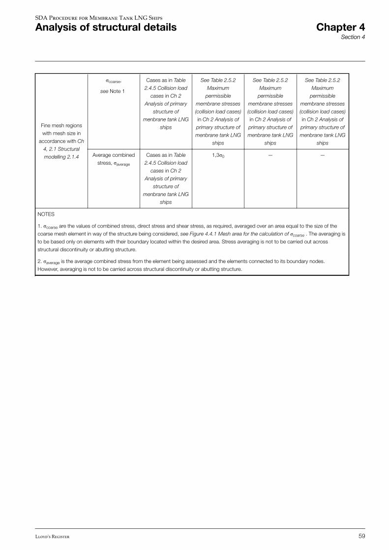
Fine mesh regions
with mesh size in
accordance with Ch
4, 2.1 Structural
modelling 2.1.4
σcoarse,
see Note 1
Cases as in Table
2.4.5 Collision load
cases in Ch 2
Analysis of primary
structure of
menbrane tank LNG
ships
See Table 2.5.2
Maximum
permissible
membrane stresses
(collision load cases)
in Ch 2 Analysis of
primary structure of
menbrane tank LNG
ships
See Table 2.5.2
Maximum
permissible
membrane stresses
(collision load cases)
in Ch 2 Analysis of
primary structure of
menbrane tank LNG
ships
See Table 2.5.2
Maximum
permissible
membrane stresses
(collision load cases)
in Ch 2 Analysis of
primary structure of
menbrane tank LNG
ships
Average combined
stress, σaverage
Cases as in Table
2.4.5 Collision load
cases in Ch 2
Analysis of primary
structure of
menbrane tank LNG
ships
1,3σ0 — —
NOTES
1. σcoarse are the values of combined stress, direct stress and shear stress, as required, averaged over an area equal to the size of the
coarse mesh element in way of the structure being considered, see Figure 4.4.1 Mesh area for the calculation of σcoarse . The averaging is
to be based only on elements with their boundary located within the desired area. Stress averaging is not to be carried out across
structural discontinuity or abutting structure.
2. σaverage is the average combined stress from the element being assessed and the elements connected to its boundary nodes.
However, averaging is not to be carried across structural discontinuity or abutting structure.
SDA Procedure for Membrane Tank LNG Ships
Analysis of structural details Chapter 4Section 4
Lloyd's Register 59
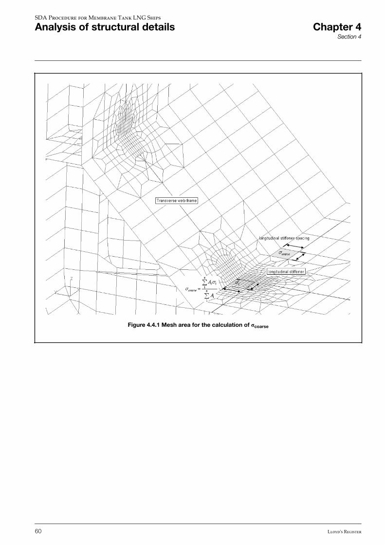
Figure 4.4.1 Mesh area for the calculation of σcoarse
SDA Procedure for Membrane Tank LNG Ships
Analysis of structural details Chapter 4Section 4
60 Lloyd's Register
CHAPTER 1 INTRODUCTION
CHAPTER 2 ANALYSIS OF PRIMARY STRUCTURE OF MENBRANE TANK LNG SHIPS
CHAPTER 3 ANALYSIS OF TRUNK DECK SCARPHING ARRANGEMENTS WITH THE AFT END
CHAPTER 4 ANALYSIS OF STRUCTURAL DETAILS
CHAPTER 5 APPENDIX A: ALTERNATIVE PROCEDURE FOR TRANSVERSE LOAD CASES (HALF-BREADTH FE MODEL)
SECTION 1 PROCEDURE TO APPLY TRANSVERSE ASYMMETRIC LOADS TOHALF-BREADTH FE MODEL
CHAPTER 6 APPENDIX B: GUIDANCE PROCEDURE TO DETERMINE LONG-TERM TRANSVERSEACCELERATIONS
SDA Procedure for Membrane Tank LNG Ships
Contents Chapter 5
Lloyd's Register 61
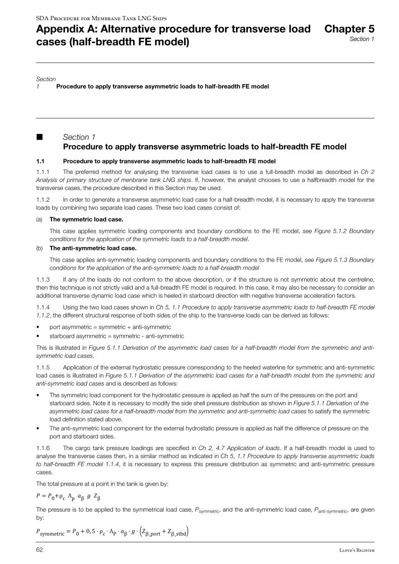
Section1 Procedure to apply transverse asymmetric loads to half-breadth FE model
n Section 1 Procedure to apply transverse asymmetric loads to half-breadth FE model
1.1 Procedure to apply transverse asymmetric loads to half-breadth FE model
1.1.1 The preferred method for analysing the transverse load cases is to use a full-breadth model as described in Ch 2Analysis of primary structure of menbrane tank LNG ships. If, however, the analyst chooses to use a halfbreadth model for thetransverse cases, the procedure described in this Section may be used.
1.1.2 In order to generate a transverse asymmetric load case for a half-breadth model, it is necessary to apply the transverseloads by combining two separate load cases. These two load cases consist of:
(a) The symmetric load case.
This case applies symmetric loading components and boundary conditions to the FE model, see Figure 5.1.2 Boundaryconditions for the application of the symmetric loads to a half-breadth model.
(b) The anti-symmetric load case.
This case applies anti-symmetric loading components and boundary conditions to the FE model, see Figure 5.1.3 Boundaryconditions for the application of the anti-symmetric loads to a half-breadth model
1.1.3 If any of the loads do not conform to the above description, or if the structure is not symmetric about the centreline,then this technique is not strictly valid and a full-breadth FE model is required. In this case, it may also be necessary to consider anadditional transverse dynamic load case which is heeled in starboard direction with negative transverse acceleration factors.
1.1.4 Using the two load cases shown in Ch 5, 1.1 Procedure to apply transverse asymmetric loads to half-breadth FE model1.1.2, the different structural response of both sides of the ship to the transverse loads can be derived as follows:
• port asymmetric = symmetric + anti-symmetric
• starboard asymmetric = symmetric - anti-symmetric
This is illustrated in Figure 5.1.1 Derivation of the asymmetric load cases for a half-breadth model from the symmetric and anti-symmetric load cases.
1.1.5 Application of the external hydrostatic pressure corresponding to the heeled waterline for symmetric and anti-symmetricload cases is illustrated in Figure 5.1.1 Derivation of the asymmetric load cases for a half-breadth model from the symmetric andanti-symmetric load cases and is described as follows:
• The symmetric load component for the hydrostatic pressure is applied as half the sum of the pressures on the port andstarboard sides. Note it is necessary to modify the side shell pressure distribution as shown in Figure 5.1.1 Derivation of theasymmetric load cases for a half-breadth model from the symmetric and anti-symmetric load cases to satisfy the symmetricload definition stated above.
• The anti-symmetric load component for the external hydrostatic pressure is applied as half the difference of pressure on theport and starboard sides.
1.1.6 The cargo tank pressure loadings are specified in Ch 2, 4.7 Application of loads. If a half-breadth model is used toanalyse the transverse cases then, in a similar method as indicated in Ch 5, 1.1 Procedure to apply transverse asymmetric loadsto half-breadth FE model 1.1.4, it is necessary to express this pressure distribution as symmetric and anti-symmetric pressurecases.
The total pressure at a point in the tank is given by:� = �0+ρc Λp �β � �βThe pressure is to be applied to the symmetrical load case, Psymmetric, and the anti-symmetric load case, Panti-symmetric, are givenby:�symmetric = �0+ 0, 5 ⋅ ρc ⋅ ΛP ⋅ �β ⋅ � ⋅ �β_port + �β_stbd
SDA Procedure for Membrane Tank LNG Ships
Appendix A: Alternative procedure for transverse loadcases (half-breadth FE model)
Chapter 5Section 1
62 Lloyd's Register
�anti− symmetric = 0, 5 ⋅ ρc ⋅ ΛP ⋅ � ⋅ �β_port − �β_stbdwhere �β = is resultant acceleration vector at angle β, see Ch 2, 4.7 Application of loads 4.7.3 and Figure 2.4.5
Internal tank pressure for transverse dynamic load cases.
Zβ = is the largest liquid height above the point where the pressure is to be determined.
Zβ_port = is the height, Zβ measured to a point on the tank boundary at the port side of the ship.
Zβ_stbd = is the height, Zβ measured to the point on the tank boundary at the starboard side of the shipcorresponding to the point used for Zβ_port
See Ch 2, 4.7 Application of loads 4.7.3 for definition of other symbols.
1.1.7 The boundary conditions for the symmetric load case and the anti-symmetric load case are as follows:
• Symmetric load case: See Figure 5.1.2 Boundary conditions for the application of the symmetric loads to a half-breadthmodel.
• Anti-symmetric load case: See Figure 5.1.3 Boundary conditions for the application of the anti-symmetric loads to a half-breadth model.
1.1.8 The FE model is to be analysed as follows:
• Sub-load case 1: Symmetric condition comprising symmetric loads and symmetric boundary conditions.
• Sub-load case 2: Anti-symmetric condition comprising antisymmetric loads and anti-symmetric boundary conditions.
1.1.9 The load cases to be compared with the stress and buckling criteria given in Ch 2 Analysis of primary structure ofmenbrane tank LNG ships are obtained as follows:
• For the port side of the ship: Sub-load case 1 + sub-load case 2.
• For the starboard side of the ship: Sub-load case 1 – sub-load case 2.
In carrying out these combinations, direct and shear stresses should be combined as indicated above and von Mises stress is tobe recalculated from the values of direct and shear stress resulting from the required combination. Buckling factor of safety is to becalculated based on the combined stresses.
SDA Procedure for Membrane Tank LNG Ships
Appendix A: Alternative procedure for transverse loadcases (half-breadth FE model)
Chapter 5Section 1
Lloyd's Register 63
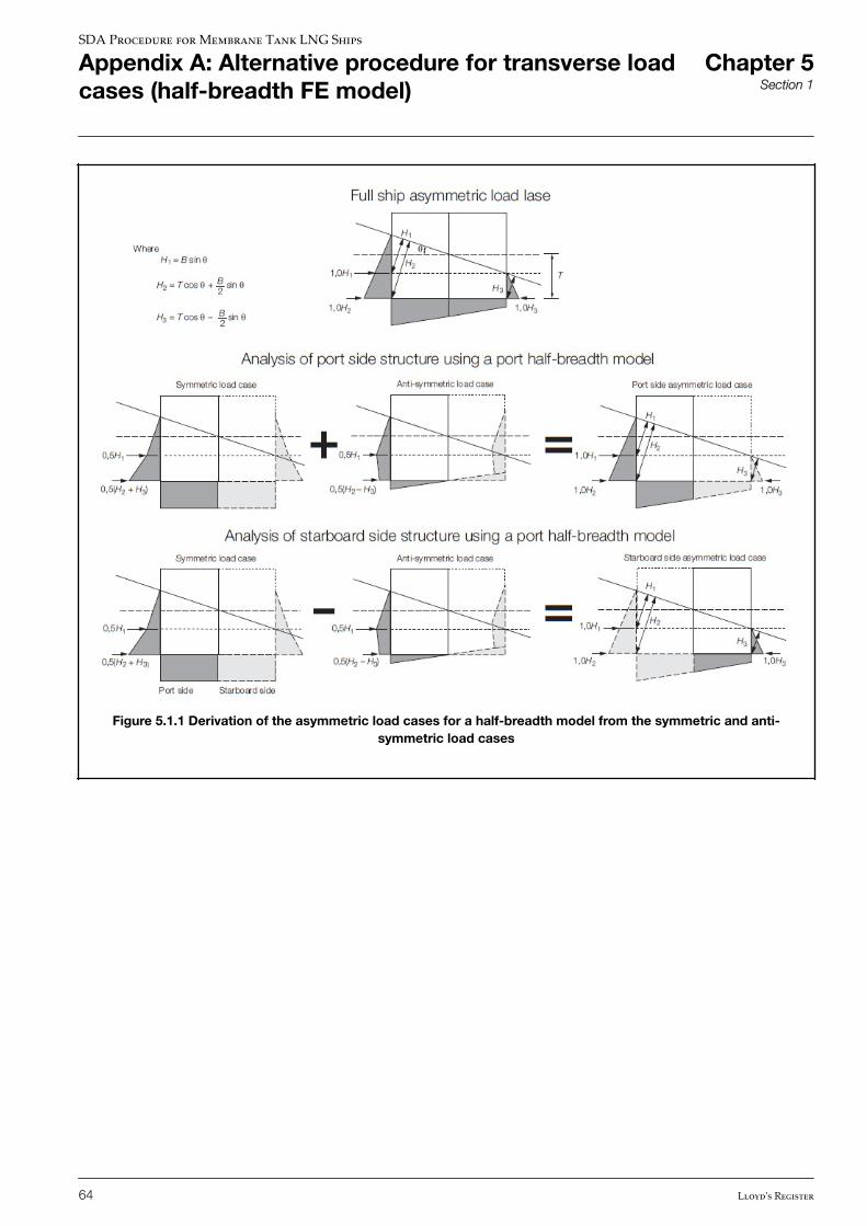
Figure 5.1.1 Derivation of the asymmetric load cases for a half-breadth model from the symmetric and anti-symmetric load cases
SDA Procedure for Membrane Tank LNG Ships
Appendix A: Alternative procedure for transverse loadcases (half-breadth FE model)
Chapter 5Section 1
64 Lloyd's Register

Figure 5.1.2 Boundary conditions for the application of the symmetric loads to a half-breadth model
Figure 5.1.3 Boundary conditions for the application of the anti-symmetric loads to a half-breadth model
SDA Procedure for Membrane Tank LNG Ships
Appendix A: Alternative procedure for transverse loadcases (half-breadth FE model)
Chapter 5Section 1
Lloyd's Register 65
CHAPTER 1 INTRODUCTION
CHAPTER 2 ANALYSIS OF PRIMARY STRUCTURE OF MENBRANE TANK LNG SHIPS
CHAPTER 3 ANALYSIS OF TRUNK DECK SCARPHING ARRANGEMENTS WITH THE AFT END
CHAPTER 4 ANALYSIS OF STRUCTURAL DETAILS
CHAPTER 5 APPENDIX A: ALTERNATIVE PROCEDURE FOR TRANSVERSE LOAD CASES (HALF-BREADTH FE MODEL)
CHAPTER 6 APPENDIX B: GUIDANCE PROCEDURE TO DETERMINE LONG-TERM TRANSVERSEACCELERATIONS
SECTION 1 WAVE SCATTER DIAGRAM AND WAVE SPECTRUM
SECTION 2 MAXIMUM LIFETIME ROLL ANGLES
SECTION 3 MAXIMUM LIFETIME TRANSVERSE ACCELERATIONS
SDA Procedure for Membrane Tank LNG Ships
Contents Chapter 6
66 Lloyd's Register
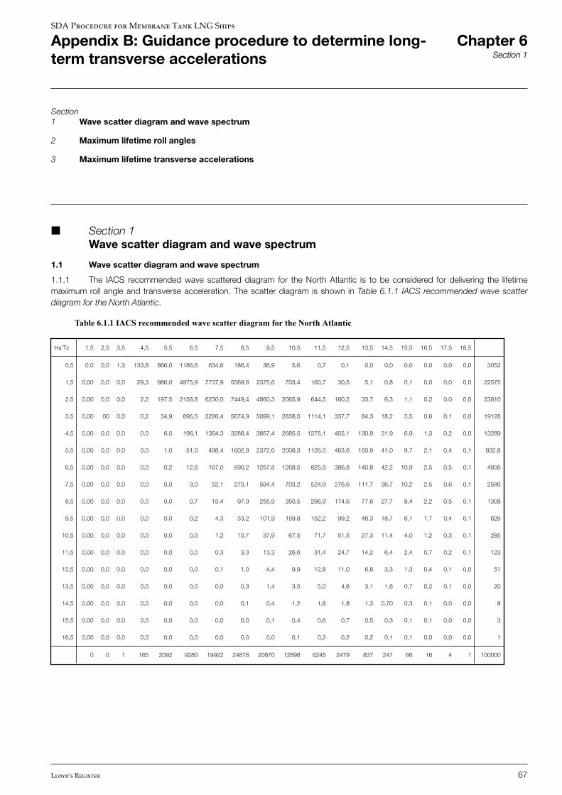
Section1 Wave scatter diagram and wave spectrum
2 Maximum lifetime roll angles
3 Maximum lifetime transverse accelerations
n Section 1 Wave scatter diagram and wave spectrum
1.1 Wave scatter diagram and wave spectrum
1.1.1 The IACS recommended wave scattered diagram for the North Atlantic is to be considered for delivering the lifetimemaximum roll angle and transverse acceleration. The scatter diagram is shown in Table 6.1.1 IACS recommended wave scatterdiagram for the North Atlantic.
Table 6.1.1 IACS recommended wave scatter diagram for the North Atlantic
Hs'Tz 1,5 2,5 3,5 4,5 5.5 6.5 7,5 8,5 9,5 10,5 11,5 12,5 13,5 14,5 15,5 16,5 17,5 18,5
0,5 0,0 0,0 1,3 133,8 866,0 1186,6 634,6 186,4 36,9 5,6 0,7 0,1 0,0 0,0 0,0 0,0 0,0 0,0 3052
1,5 0,00 0,0 0,0 29,3 986,0 4975,9 7737,9 5569,6 2375,6 703,4 160,7 30,5 5,1 0,8 0,1 0,0 0,0 0,0 22575
2,5 0,00 0,0 0,0 2,2 197,5 2158,8 6230,0 7449,4 4860,3 2065,9 644,5 160,2 33,7 6,3 1,1 0,2 0,0 0,0 23810
3,5 0,00 00 0,0 0,2 34,9 695,5 3226,4 5674,9 5099,1 2838,0 1114,1 337,7 84,3 18,2 3,5 0,6 0,1 0,0 19128
4,5 0,00 0,0 0,0 0,0 6,0 196,1 1354,3 3288,4 3857,4 2685,5 1275,1 455,1 130,9 31,9 6,9 1,3 0,2 0,0 13289
5,5 0,00 0,0 0,0 0,0 1,0 51,0 498,4 1602,9 2372,6 2008,3 1126,0 463,6 150,9 41,0 9,7 2,1 0,4 0,1 832.8
6,5 0,00 0,0 0,0 0,0 0,2 12,6 167,0 690,2 1257,8 1268,5 825,9 386,8 140,8 42,2 10,9 2,5 0,5 0,1 4806
7,5 0,00 0,0 0,0 0,0 0,0 3,0 52,1 270,1 594,4 703,2 524,9 276,6 111,7 36,7 10,2 2,5 0,6 0,1 2586
8,5 0,00 0,0 0,0 0,0 0,0 0,7 15,4 97,9 255,9 350,5 296,9 174,6 77,6 27,7 8,4 2,2 0,5 0,1 1308
9,5 0,00 0,0 0,0 0,0 0,0 0,2 4,3 33,2 101,9 159,8 152,2 99,2 48,3 18,7 6,1 1,7 0,4 0,1 626
10,5 0,00 0,0 0,0 0,0 0,0 0,0 1,2 10,7 37,9 67,5 71,7 51,5 27,3 11,4 4,0 1,2 0,3 0,1 285
11,5 0,00 0,0 0,0 0,0 0,0 0,0 0,3 3,3 13,3 26,6 31,4 24,7 14,2 6,4 2,4 0,7 0,2 0,1 123
12,5 0,00 0,0 0,0 0,0 0,0 0,0 0,1 1,0 4,4 9,9 12,8 11,0 6,8 3,3 1,3 0,4 0,1 0,0 51
13,5 0,00 0,0 0,0 0,0 0,0 0,0 0,0 0,3 1,4 3,5 5,0 4,6 3,1 1,6 0,7 0,2 0,1 0,0 20
14,5 0,00 0,0 0,0 0,0 0,0 0,0 0,0 0,1 0,4 1,2 1,8 1,8 1,3 0,70 0,3 0,1 0,0 0,0 8
15,5 0,00 0,0 0,0 0,0 0,0 0,0 0,0 0,0 0,1 0,4 0,6 0,7 0,5 0,3 0,1 0,1 0,0 0,0 3
16,5 0,00 0,0 0,0 0,0 0,0 0,0 0,0 0,0 0,0 0,1 0,2 0,2 0,2 0,1 0,1 0,0 0,0 0,0 1
0 0 1 165 2092 9280 19922 24878 20870 12898 6245 2479 837 247 66 16 4 1 100000
SDA Procedure for Membrane Tank LNG Ships
Appendix B: Guidance procedure to determine long-term transverse accelerations
Chapter 6Section 1
Lloyd's Register 67
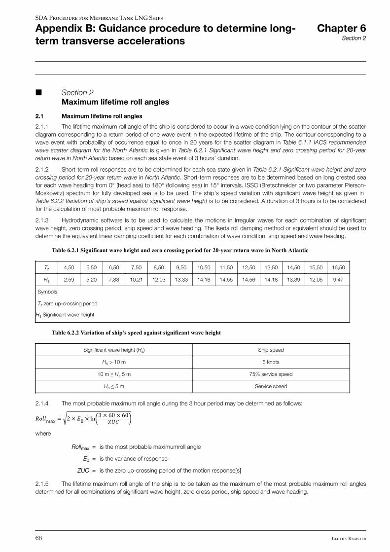
n Section 2 Maximum lifetime roll angles
2.1 Maximum lifetime roll angles
2.1.1 The lifetime maximum roll angle of the ship is considered to occur in a wave condition lying on the contour of the scatterdiagram corresponding to a return period of one wave event in the expected lifetime of the ship. The contour corresponding to awave event with probability of occurrence equal to once in 20 years for the scatter diagram in Table 6.1.1 IACS recommendedwave scatter diagram for the North Atlantic is given in Table 6.2.1 Significant wave height and zero crossing period for 20-yearreturn wave in North Atlantic based on each sea state event of 3 hours’ duration.
2.1.2 Short-term roll responses are to be determined for each sea state given in Table 6.2.1 Significant wave height and zerocrossing period for 20-year return wave in North Atlantic. Short-term responses are to be determined based on long crested seafor each wave heading from 0° (head sea) to 180° (following sea) in 15° intervals. ISSC (Bretschneider or two parameter Pierson-Moskowitz) spectrum for fully developed sea is to be used. The ship's speed variation with significant wave height as given in Table 6.2.2 Variation of ship’s speed against significant wave height is to be considered. A duration of 3 hours is to be consideredfor the calculation of most probable maximum roll response.
2.1.3 Hydrodynamic software is to be used to calculate the motions in irregular waves for each combination of significantwave height, zero crossing period, ship speed and wave heading. The Ikeda roll damping method or equivalent should be used todetermine the equivalent linear damping coefficient for each combination of wave condition, ship speed and wave heading.
Table 6.2.1 Significant wave height and zero crossing period for 20-year return wave in North Atlantic
Tz 4,50 5,50 6,50 7,50 8,50 9,50 10,50 11,50 12,50 13,50 14,50 15,50 16,50
Hs 2,59 5,20 7,88 10,21 12,03 13,33 14,16 14,55 14,56 14,18 13,39 12,05 9,47
Symbols:
Tz zero up-crossing period
Hs Significant wave height
Table 6.2.2 Variation of ship’s speed against significant wave height
Significant wave height (Hs) Ship speed
Hs > 10 m 5 knots
10 m ≥ Hs 5 m 75% service speed
Hs ≤ 5 m Service speed
2.1.4 The most probable maximum roll angle during the 3 hour period may be determined as follows:����max = 2 × �0 × ln 3 × 60 × 60���where
Rollmax = is the most probable maximumroll angle
E0 = is the variance of response
ZUC = is the zero up-crossing period of the motion response[s]
2.1.5 The lifetime maximum roll angle of the ship is to be taken as the maximum of the most probable maximum roll anglesdetermined for all combinations of significant wave height, zero cross period, ship speed and wave heading.
SDA Procedure for Membrane Tank LNG Ships
Appendix B: Guidance procedure to determine long-term transverse accelerations
Chapter 6Section 2
68 Lloyd's Register
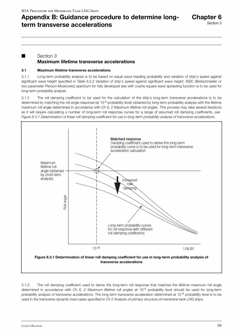
n Section 3 Maximum lifetime transverse accelerations
3.1 Maximum lifetime transverse accelerations
3.1.1 Long-term probability analysis is to be based on equal wave heading probability and variation of ship's speed againstsignificant wave height specified in Table 6.2.2 Variation of ship’s speed against significant wave height. ISSC (Bretschneider ortwo parameter Pierson-Moskowitz) spectrum for fully developed sea with cosine square wave spreading function is to be used forlong-term probability analysis
3.1.2 The roll damping coefficient to be used for the calculation of the ship's long-term transverse accelerations is to bedetermined by matching the roll angle response (at 10-8 probability level) obtained by long-term probability analysis with the lifetimemaximum roll angle determined in accordance with Ch 6, 2 Maximum lifetime roll angles. This process may take several iterationsas it will require calculating a number of long-term roll response curves for a range of assumed roll damping coefficients, see Figure 6.3.1 Determination of linear roll damping coefficient for use in long-term probability analysis of transverse accelerations.
Figure 6.3.1 Determination of linear roll damping coefficient for use in long-term probability analysis oftransverse accelerations
3.1.3 The roll damping coefficient used to derive the long-term roll response that matches the lifetime maximum roll angledetermined in accordance with Ch 6, 2 Maximum lifetime roll angles at 10–8 probability level should be used for long-termprobability analysis of transverse accelerations. The long term transverse acceleration determined at 10–8 probability level is to beused in the transverse dynamic load cases specified in Ch 2 Analysis of primary structure of menbrane tank LNG ships.
SDA Procedure for Membrane Tank LNG Ships
Appendix B: Guidance procedure to determine long-term transverse accelerations
Chapter 6Section 3
Lloyd's Register 69

© Lloyd’s Register Group Limited 2016 Published by Lloyd’s Register Group Limited
Registered office (Reg. no. 08126909) 71 Fenchurch Street, London, EC3M 4BS
United Kingdom
Lloyd’s Register is a trading name of Lloyd’s Register Group Limited and its subsidiaries. For further details please see
http://www.lr.org/entities
Lloyd's Register Group Limited, its affiliates and subsidiaries and their respective officers, employees or agents are, individually and collectively, referred to in this clause as ‘Lloyd's Register’. Lloyd's Register assumes no responsibility and shall not be liable to any person for any loss, damage or expense caused by reliance on the information or advice in this document or howsoever provided, unless that person has signed a contract with the relevant Lloyd's Register entity for the provision of this information or advice and in that case any responsibility or liability is exclusively on the terms and conditions set out in that contract.
© Lloyd’s Register, 2016