Safety, Site Planning and Shielding Contents Common PET
16
1 Safety, Site Planning and Safety, Site Planning and Shielding Shielding Richard E. Wendt III, Nancy Swanston and William D. Erwin Department of Imaging Physics UT M. D. Anderson Cancer Center Contents • Safety – Patients – Personnel – Public • Site Planning – Source flows – Work flow – Adjacencies – Equipment • Shielding – Localized – Structural Common PET Radionuclides Nuclide Δ(β + + γ±)/ Δ(total) Δ(total)/Abun- dance(γ±) ×10 -13 Mean Life (min) Avg. Life/ Scan time Dose Rate Constant C-11 1.003 1.123 29.42 0.98 0.148 N-13 0.999 1.212 14.38 0.48 0.148 O-15 0.996 1.049 2.94 0.10 0.148 F-18 1.000 1.049 158.40 5.28 0.143 Cu 62 0 993 1 886 14 05 0 47 Cu-62 0.993 1.886 14.05 0.47 Cu-64 0.742 1.404 1099.65 36.66 0.029 Ga-68 0.983 1.511 98.21 3.27 0.134 Rb-82 0.952 2.097 1.88 0.06 0.159 I-124 0.332 4.416 8685.71 289.52 0.185 Δ(β++ γ±)/Δ(total) : Energy released by “useful” positrons and annihilation photons over total energy released. Data from MIRD Decay Schemes (Δ in Gy-kg/Bq-s). Abundance of annihilation photons from Lund NuDat database: http://nucleardata.nuclear.lu.se/Database/Nudat/. External effective dose equivalent dose rate constants from TG108 (μSv-m 2 /MBq-hr). A scanning time of 30 minutes is assumed. F-18 K.F. Eckerman & A. Endo, MIRD Radionuclide Data and Decay Schemes, 2 nd Ed., Reston: Society of Nuclear Medicine, 2008.
Transcript of Safety, Site Planning and Shielding Contents Common PET

1
Safety, Site Planning and Safety, Site Planning and ShieldingShieldinggg
Richard E. Wendt III,Nancy Swanston and William D. Erwin
Department of Imaging PhysicsUT M. D. Anderson Cancer Center
Contents• Safety
– Patients– Personnel– Public
• Site Planning– Source flows– Work flow– Adjacencies
– Equipment • Shielding– Localized– Structural
Common PET RadionuclidesNuclide Δ(β++ γ±)/
Δ(total)Δ(total)/Abun-dance(γ±) ×10-13
Mean Life (min)
Avg. Life/ Scan time
Dose Rate Constant
C-11 1.003 1.123 29.42 0.98 0.148N-13 0.999 1.212 14.38 0.48 0.148O-15 0.996 1.049 2.94 0.10 0.148F-18 1.000 1.049 158.40 5.28 0.143Cu 62 0 993 1 886 14 05 0 47Cu-62 0.993 1.886 14.05 0.47Cu-64 0.742 1.404 1099.65 36.66 0.029Ga-68 0.983 1.511 98.21 3.27 0.134Rb-82 0.952 2.097 1.88 0.06 0.159I-124 0.332 4.416 8685.71 289.52 0.185
Δ(β++ γ±)/Δ(total) : Energy released by “useful” positrons and annihilation photons over total energy released. Data from MIRD Decay Schemes (Δ in Gy-kg/Bq-s).Abundance of annihilation photons from Lund NuDat database: http://nucleardata.nuclear.lu.se/Database/Nudat/.External effective dose equivalent dose rate constants from TG108 (μSv-m2/MBq-hr).A scanning time of 30 minutes is assumed.
F-18
K.F. Eckerman & A. Endo, MIRD Radionuclide Data and Decay Schemes, 2nd Ed., Reston: Society of Nuclear Medicine, 2008.

2
I-124
K.F. Eckerman & A. Endo, MIRD Radionuclide Data and Decay Schemes, 2nd Ed., Reston: Society of Nuclear Medicine, 2008.
Useful Energy/Total Energy
0.8
1.0
1.2
Tota
l Ene
rgy
0.0
0.2
0.4
0.6
C-11 N-13 O-15 F-18 Cu-62 Cu-64 Ga-68 Rb-82 I-124
Radionuclide
Use
ful E
nerg
y/T
Energy per Annihilation Photon
3.00
3.50
4.00
4.50
5.00
hoto
n (1
00 fJ
)
0.00
0.50
1.00
1.50
2.00
2.50
C-11 N-13 O-15 F-18 Cu-62 Cu-64 Ga-68 Rb-82 I-124
Radionuclide
Ener
gy/A
nnih
ilatio
n Ph
Dose Rate Constants
0.12
0.14
0.16
0.18
0.2
Sv-
m^2
/MBq
-hr)
0
0.02
0.04
0.06
0.08
0.1
C-11 N-13 O-15 F-18 Cu-64 Ga-68 Rb-82 I-124
Radionuclide
Dos
e Ra
te C
onst
ant (
uS
3
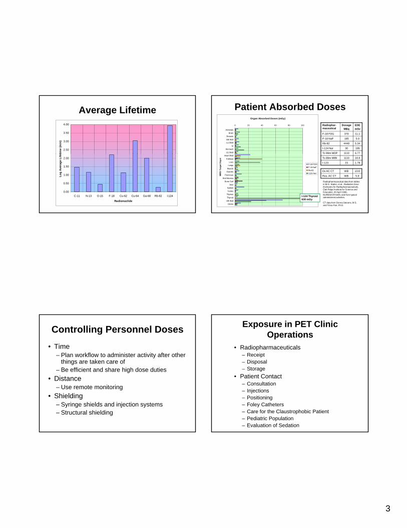
Average Lifetime
2.50
3.00
3.50
4.00
time
(min
)
0.00
0.50
1.00
1.50
2.00
C-11 N-13 O-15 F-18 Cu-62 Cu-64 Ga-68 Rb-82 I-124
Radionuclide
Log
Aver
age
Life
t
Patient Absorbed DosesRadiophar-maceutical
DosageMBq
EDEmSv
F-18 FDG 370 11.1
F-18 NaF 185 5.0
Rb-82 4440 5.34
I-124 NaI 30 195
Tc-99m MDP 1110 6.77
Organ Absorbed Doses (mGy)
0 20 40 60 80 100
AdrenalsBrain
BreastsGB WallLLI Wall
SIStomachULI Wall
Tc-99m MIBI 1110 16.6
I-123 15 1.78
Dx AC CT WB 13.6
Res. AC CT WB 5.9
Radiopharmaceutical data from tables in M.G. Stabin, et al., Radiation Dose Estimates for Radiopharmaceuticals, Oak Ridge Institute for Science and Education, 30 April 1996, NUREG/CR-6345, and from typical administered activities.
CT data from Donna Stevens, M.S. and Tinsu Pan, Ph.D.
Heart WallKidneys
LiverLungs
MuscleOvaries
PancreasRed Marrow
Bone SurfSkin
SpleenTestes
ThymusThyroid
UB WallUterus
MIR
D T
arge
t Org
an
F-18 FDGF-18 NaFRb-82I-124 NaI
I-124 Thyroid630 mGy
Controlling Personnel Doses• Time
– Plan workflow to administer activity after other things are taken care of
– Be efficient and share high dose duties• Distance
– Use remote monitoring• Shielding
– Syringe shields and injection systems– Structural shielding
• Radiopharmaceuticals– Receipt– Disposal– Storage
Exposure in PET Clinic Operations
• Patient Contact– Consultation– Injections– Positioning– Foley Catheters– Care for the Claustrophobic Patient– Pediatric Population– Evaluation of Sedation

4
Syringe ShieldsUT MDACC based on
Cardinal Health’s
97% atten97% atten
Z-PET
88% atten88% atten
Gaard Lock
→→100% atten100% atten
Angel Shield Injector(Pinestar)
Manual Injector (Biodex) Infusion System (MEDRAD)
Delivery of Unit Doses
2” Pb L-block
2” Pb4” Pb glass
PET Dose Assay Station
6 cm Pb rings
~ 1.25 cm~ 6 cm
Exposure Rate (20 mCi 18F)
~ 73 R/h ~ 3.2 R/h
~ 18 cm
~ 0.35 R/h
5
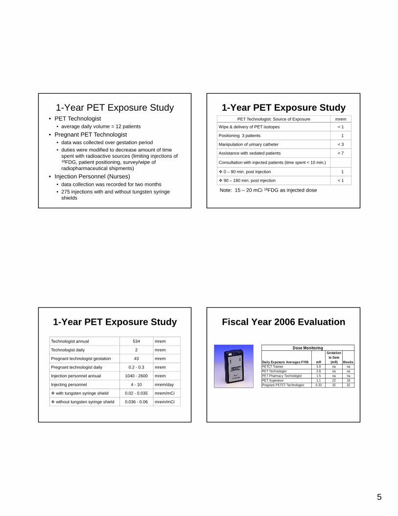
• PET Technologist• average daily volume = 12 patients
• Pregnant PET Technologist• data was collected over gestation period• duties were modified to decrease amount of time
1-Year PET Exposure Study
duties were modified to decrease amount of time spent with radioactive sources (limiting injections of 18FDG, patient positioning, survey/wipe of radiopharmaceutical shipments)
• Injection Personnel (Nurses)• data collection was recorded for two months• 275 injections with and without tungsten syringe
shields
PET Technologist: Source of Exposure mrem
Wipe & delivery of PET isotopes < 1
Positioning 3 patients 1
Manipulation of urinary catheter < 3
1-Year PET Exposure Study
Assistance with sedated patients < 7
Consultation with injected patients (time spent < 10 min.)
0 – 90 min. post injection 1
90 – 180 min. post injection < 1
Note: 15 – 20 mCi 18FDG as injected dose
Technologist annual 534 mrem
Technologist daily 2 mrem
Pregnant technologist gestation 43 mrem
1-Year PET Exposure Study
Pregnant technologist daily 0.2 - 0.3 mrem
Injection personnel annual 1040 - 2600 mrem
Injecting personnel 4 - 10 mrem/day
with tungsten syringe shield 0.02 - 0.035 mrem/mCi
without tungsten syringe shield 0.036 - 0.06 mrem/mCi
Daily Exposure Averages FY06 mR
Gestation to Date
(mR) Weeks
Dose Monitoring
Fiscal Year 2006 Evaluation
PETCT Trainee 3.9 na naPET Technologist 2.8 na naPET Pharmacy Technologist 1.5 na naPET Supervisor 1.1 22 16Pregnant PETCT Technologist 0.33 32 32
6
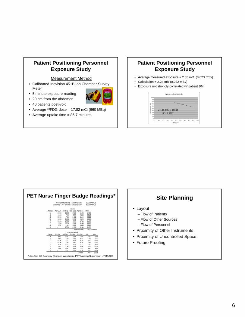
Measurement Method• Calibrated Inovision 451B Ion Chamber Survey
Meter5 i t di
Patient Positioning Personnel Exposure Study
• 5 minute exposure reading• 20 cm from the abdomen• 40 patients post-void• Average 18FDG dose = 17.82 mCi (660 MBq)• Average uptake time = 86.7 minutes
• Average measured exposure = 2.33 mR (0.023 mSv)• Calculation = 2.24 mR (0.022 mSv)• Exposure not strongly correlated w/ patient BMI
Patient Positioning Personnel Exposure Study
Exposure vs. Body Mass Index
y = -10.041x + 994.12R2 = 0.1697
0
100
200
300
400
500
600
700
800
900
1000
0.0 5.0 10.0 15.0 20.0 25.0 30.0 35.0 40.0 45.0 50.0
BMI (kg/m2)
Tota
l exp
osur
e (m
R)
PET Nurse Finger Badge Readings*Skin Limit (mrem): 12500/quarter 50000Annual
Extremity Limit (mrem): 12500/quarter 50000Annual
mremNurse Apr-Jun Jul-Sep Oct-Dec Apr-Dec Max.
A 2480 1920 1720 6120 2480B 1340 790 360 2490 1340C 3900 730 1480 6110 3900D 1630 1620 1370 4620 1630E 2490 1650 560 4700 2490F 1750 2620 1760 6130 2620
mrem per patientNurse Apr-Jun Jul-Sep Oct-Dec Apr-Dec Min. Max.
A 4.81 6.47 6.99 5.69 4.81 6.99B 7.05 3.24 2.78 4.33 2.78 7.05C 12.18 3.17 4.38 6.75 3.17 12.18D 10.76 7.45 4.80 6.74 4.80 10.76E 8.29 6.17 2.37 5.23 2.37 8.29F 7.92 12.38 6.73 8.56 6.73 12.38G 2.44 0.97 6.51 2.51 0.97 6.51H - 13.51 6.71 5.74 6.71 13.51
Overall: 0.97 13.51
* Apr-Dec ’05 Courtesy Shannon Worchesik, PET Nursing Supervisor, UTMDACC
G 210 94 1280 1584 1280H - 1000 2180 3180 2180
Overall Max.: 3900/quarter
Site Planning
• Layout– Flow of Patients– Flow of Other Sources
Flow of Personnel– Flow of Personnel• Proximity of Other Instruments• Proximity of Uncontrolled Space• Future Proofing

7
Uptake Rooms• For F-18 FDG imaging, two or three uptake
rooms are needed to support a single scanner.• As scanners become more efficient, this number
will increase since the uptake time for FDG will not change.g
• Uptake rooms should be quiet and dark.• Remote monitoring via CCTV, intercoms or
mirrors is desirable.• Uptake rooms should be shielded to protect
personnel working with a patient prior to injection.
Adjacencies• Nuclear medicine equipment including
gamma cameras and well counters should be protected from PET by shielding or distance.
• PET patients should have a dedicated toilet that does not require their walking near sensitive instruments.
• Assume the worst for adjacent areas not under the licensee’s control.
Future Proofing• We have seen a steady growth in FDG
PET/CT which justifies our having shielded to worst case workloads.
• Envisioning future growth as well as g gpossible changes in the use of adjacent space can avoid costly retrofitting.
• It is desirable to have a physics lab, shielded if necessary, where phantoms may be prepared and later stored for decay.
Unshielded Dose Rates• 20 μSv/hr (2 mrem/hr) is the dose rate from an
unshielded point source of F-18 at – 1 cm from 14 kBq (378 μCi)– 10 cm from 1.4 MBq (37.8 μCi)– 1 m from 140 Mbq (3.78 mCi)– 2 m from 559 Mbq (15.1 mCi)
• Since PET sources are relatively steady, the “2 mrem in any one hour” rule is usually covered by the weekly limits.
• CT could be an issue if PET protection is afforded mainly by distance, rather than shielding.

8
Weekly Limits
• We shield public areas to 2 mrem/wk (20 μSv/wk) and controlled areas to 10 mrem/wk (100 μSv/wk).
• The actual public exposure is practically• The actual public exposure is practically much lower because most public areas are well below 20 μSv/wk when the worst spots are at 20 μSv/wk.
Occupancy Factors• NCRP 147 gives modern occupancy factor
recommendations.• Fractional occupancy factors make sense
for public areas.p• NCRP 49 clearly states that unity
occupancy factors should be used in controlled areas.
• The example in TG108 has T=0.25 for a controlled corridor.
Shielding
• Structural shielding is typically necessary for clinical PET facilities.
• AAPM Task Group 108 Report and several talks from the AAPM Summerseveral talks from the AAPM Summer School 2007 address shielding in greater detail than we can here.
• A neglected area is the shielding offered by the PET/CT instrument itself.
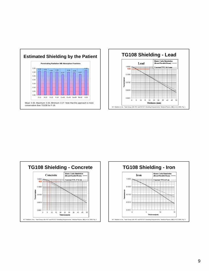
F-18 Shielding by the Patient• TG108 recommends assuming 36% absorption
by the patient based upon an analysis of published external measurements of patients.
• TG108 sanity checks this with the MIRD whole body absorbed fraction (MIRD Pamphlet 5body absorbed fraction (MIRD Pamphlet 5, revised – 34% for 500 keV photons).
• Using the penetrating and non-penetrating energies in the MIRD decay scheme and the 70 kg WB S-value from the Olinda software for F-18 gives 30% absorption of photons.
9
Estimated Shielding by the PatientPenetrating Radiation WB Absorption Fractions
0.32 0.31 0.30 0.30
0.270.30 0.30
0.27
0.33
0.25
0.30
0.35
0.00
0.05
0.10
0.15
0.20
C-11 N-13 O-15 F-18 Cu-62 Cu-64 Ga-68 Rb-82 I-124
Mean: 0.30, Maximum: 0.33, Minimum: 0.27. Note that this approach is more conservative than TG108 for F-18.
TG108 Shielding - Lead
0.50.5
M.T. Madsen, et al., “Task Group 108: PET and PET/CT Shielding Requirements,” Medical Physics, 33(1):4-15, 2006, Fig. 1
TG108 Shielding - Concrete
0.50.5
M.T. Madsen, et al., “Task Group 108: PET and PET/CT Shielding Requirements,” Medical Physics, 33(1):4-15, 2006, Fig. 2
TG108 Shielding - Iron
M.T. Madsen, et al., “Task Group 108: PET and PET/CT Shielding Requirements,” Medical Physics, 33(1):4-15, 2006, Fig. 3

10
TG 108 Shielding Approach
• Calculate a “reduction factor,” Rt, that converts the initial activity or dose rate at the start of a interval to the average quantity during that intervalquantity during that interval.
• Calculate the weekly dose using the patient-shielded initial activity, the duration of the event, the number of events a week, and the dose reduction factor.
TG 108 Shielding Approach
• Calculate the required transmission factor of a barrier by incorporating the occupancy factor and the weekly dose limit.
• Convert the transmission factor to a• Convert the transmission factor to a thickness of a particular material using the Monte Carlo simulation results in Table IV or the fits of the Archer equations to them.
What is a Source?• A “source” is activity at a particular location.• The source comprises numerous different
physical entities that occupy that location during the course of the week.
• An individual patient contributes to the source in the uptake room, the source in the toilet, the source in the scanner room, the source in the dressing room, and perhaps the source in the waiting room over the course of his or her study.
Source Locations

11
Uptake Room Calculation
]1[443.1
)0()(
21
693.021 T
t
t
et
T
tDtDR
−
−××=
×=
&
2
0
2
m
hr MBq hr-MBq
m-μSv 092.0)(
d
RtAtD
tUU
U
×××=
Note that D(t) is the cumulative dose from time zero to time t, not the dose rate at time t. The dose rate constant 0.092 for F-18 includes the self-shielding afforded by the patient (i.e., it is 64% of 0.1443).
Uptake Room Calculation
832.0hr 0.1 MBq 370hrMBq
m-μSv 092.02
×××
832.0]1[60
8.109443.1 8.10960693.0
=−××=×
−eRt
Sv 14.3m 9
m-Sv 3.28)m 3 min,60(
m m-Sv 3.28
m hr-MBq)uptakemin60(
2
2
2
2
2
μμ
μ
==
=
=
D
d
dD
Uptake Room Calculation
m 3at Sv/pt143pts/wk331 0
μSv/wk 20)(
××=
××=
μ
Uw tDNTPB
m 3at 0.193Sv/pt 14.3pts/wk 331.0
=×× μ
Look up B = 0.193 in Table IV of TG108 to determine that this degree of attenuation requires about 10 mm of lead, 15 cm of concrete or 4.5 cm of iron.
Multiple Sources
A point is irradiated by multiple sources at different distance through various amounts of shielding.
12
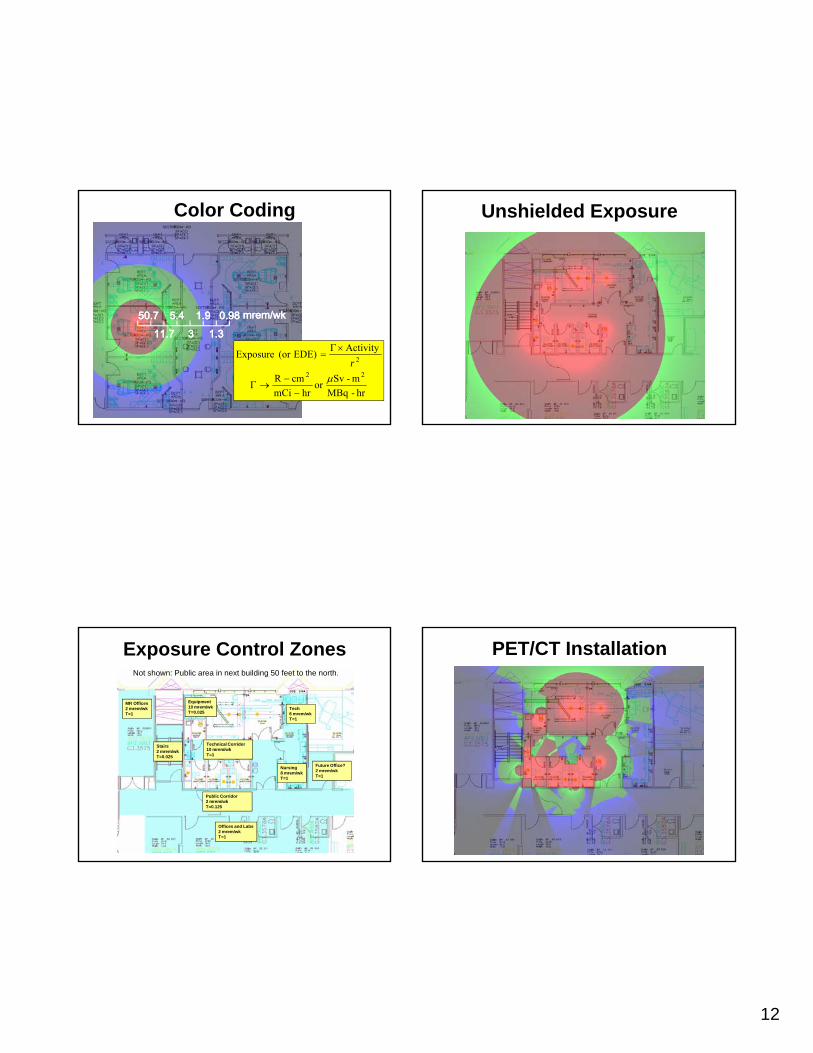
Color Coding
50.750.711.711.7
5.45.433
1.91.91.31.3
0.980.98 mrem/wkmrem/wk
hr-MBqm-Svor
hrmCicmR
ActivityEDE)(or Exposure
22
2
μ−
−→Γ
×Γ=
r
Unshielded Exposure
Exposure Control ZonesNot shown: Public area in next building 50 feet to the north.
MR Offices2 mrem/wkT=1
Tech6 mrem/wkT=1
Technical CorridorSt i
Equipment10 mrem/wkT=0.025
Nursing8 mrem/wkT=1
Future Office?2 mrem/wkT=1
Technical Corridor10 mrem/wkT=1
Public Corridor2 mrem/wkT=0.125
Stairs2 mrem/wkT=0.025
Offices and Labs2 mrem/wkT=1
PET/CT Installation
13
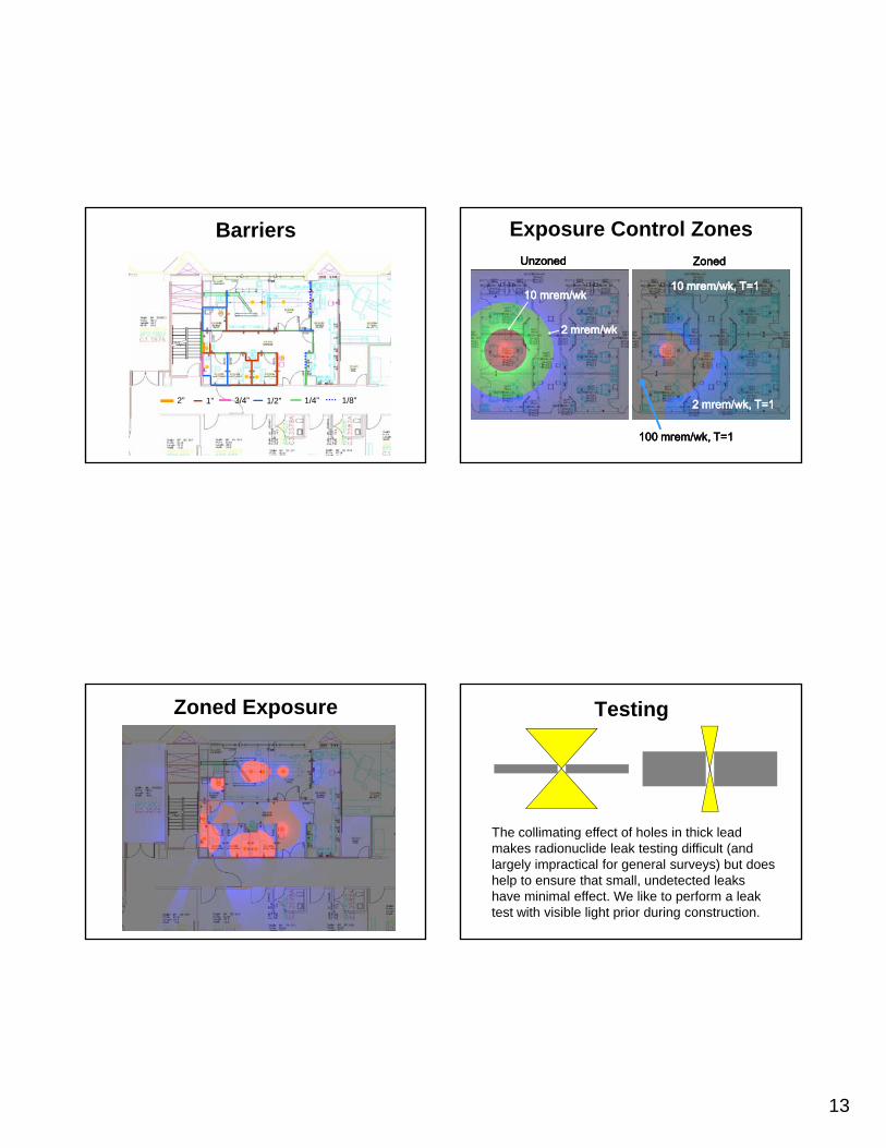
Barriers
1”2” 1/2”3/4” 1/4” 1/8”
Exposure Control ZonesUnzonedUnzoned
10 mrem/wk, T=110 mrem/wk, T=1
ZonedZoned
10 mrem/wk10 mrem/wk
2 mrem/wk2 mrem/wk
2 mrem/wk, T=12 mrem/wk, T=1
100 mrem/wk, T=1100 mrem/wk, T=1
Zoned Exposure Testing
The collimating effect of holes in thick lead makes radionuclide leak testing difficult (and largely impractical for general surveys) but does help to ensure that small, undetected leaks have minimal effect. We like to perform a leak test with visible light prior during construction.

14
Wall Systems Uptake Rooms Floor
Scan Room Floor Scan Room Ceiling

15
Scan Room Wall Scan Room Wall
Uptake Rooms Walls Penetrations

16
Penetrations Resources• M.T. Madsen, et al., “AAPM Task Group 108: PET and PET/CT
Shielding Requirements,” Medical Physics, 33(1):4-15, 2006, http://www.aapm.org/pubs/reports/RPT_108.pdf
• W.S. Snyder, et al., MIRD Pamplet 5, Revised, 1978, http://interactive.snm.org/docs/MIRD%20Pamphlet%205.pdf
• M.G. Stabin, et al., Radiation Dose Estimates for Radiopharmaceuticals, Oak Ridge Institute for Science and Education, 30 April 1996, NUREG/CR-6345, , p , ,http://www.nrc.gov/reading-rm/doc-collections/nuregs/contract/cr6345/
• AAPM Summer School 2007, various shielding talks, http://www.aapm.org/meetings/07SS/
• R.L Metzger, “Shielding Design for PET Clinics,” HPS Midyear Symposium, 2006, http://www.radsafe.com/documents/PETshieldHPS.ppt, accessed June 2008.
• K.F. Eckerman & A. Endo, MIRD Radionuclide Data and Decay Schemes, 2nd Ed., Reston: Society of Nuclear Medicine, 2008