SA DE/X - IKO International
8
SA…DE Ⅱ 265 Ⅱ 266 SA…DE/X SA…DE/S
Transcript of SA DE/X - IKO International
SA…DE
Ⅱ̶265 Ⅱ̶266
SA…
DE
/XS
A…D
E/S
1N=0.102kgf=0.2248lbs.1mm=0.03937inch
θ-table
Optical linear encoderscale head
Mechanical stopper
X-table
Linear Way
Crossed roller bearing
Moving magnet
Mechanical stopper
Stator coil
Stator coil
Moving magnet
Lost motion
Parallelism in table motion A
Parallelism in table motion B
Attitude accuracy
Straightness
Backlash
−
−
−
−
−
−
XY-axis: ±0.0005θ-axis: ±0.5 ~ 1.3 sec
Alignment Stage SA
Driving method
Material of table and bed
Sensor
Linear motor
XY-axis: Linear Way(ball type)
Lubrication part "C-Lube" is built-in
High carbon steel
Provided as standard
θ-axis: Crossed Roller Bearing
(except for θ-axis and SA65DE/X)
SA・・・DE
0.50.1 0.50.1
500270 800400
2.2
720deg/sec
Max. torque0.5N·m
Max. torque2.0N·m
Max. torque4.0N·m
Effective operating angle50degree
Effective operating angle60degree
Effective operating angle280degree
Rated torque0.06N·m
0.64sec5625pulse/deg
0.36sec10000pulse/deg
0.25sec14400pulse/deg
Rated torque0.4N·m
Rated torque1.2N·m
6.8
400deg/sec
12.3
270deg/sec
SA65DE/X SA120DE/X SA65DE/S SA120DE/S SA200DE/S
70
15
5.9
20
±0.5 ±1.3sec ±0.8sec ±0.5sec
15
65 120
25 22
65
30
200
25
120
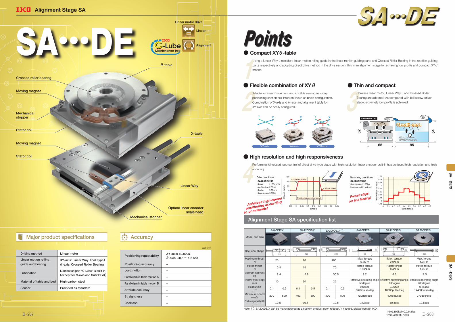
Alignment Stage SA specification list
Model and size
Sectional shape
Effective stroke lengthmm
Resolutionμm
Rated thrustN
Maximum load masskg
Maximum thrustN
Positioning repeatabilityμm
Maximum speedmm/s
1● Compact XYθ-table
Using a Linear Way L miniature linear motion rolling guide in the linear motion guiding parts and Crossed Roller Bearing in the rotation guiding
parts respectively and adopting direct drive method in the drive section, this is an alignment stage for achieving low profile and compact XYθ
motion.
2● Flexible combination of XYθ
X-table for linear movement and θ-table serving as rotary
positioning section are listed on lineup as basic configuration.
Combination of X-axis and θ-axis and alignment table for
XY-axis can be easily configured.
4● High resolution and high responsiveness
Performing full-closed loop control of direct drive-type stage with high resolution linear encoder built-in has achieved high resolution and high
accuracy.
3● Thin and compact
Coreless linear motor, Linear Way L and Crossed Roller
Bearing are adopted. As compared with ball screw-driven
stage, extremely low profile is achieved.
Points
Linear motion rolling
guide and bearing
Lubrication
Positioning repeatability
Positioning accuracy −
Major product specifications Accuracy
unit: mm
Linear motor drive
Alignment
Linear
Credit cardCredit card
XY-axis Xθ-axis XYθ-axis
3
Note(1)SA200DE/X can be manufactured as a custom product upon request. If needed, please contact IKO.
200
30
SA200DE/X(1)
0.1
400 800
0.5
400
70
30.0
25
±0.5
25
3.5
2.4
10
±0.5
Drive conditions
Achieves high-speed
positioning according
to commands!
Spe
ed m
m/s
Time s
Precise steps
for fine feeding!
Trav
el d
ista
nce
secs
Travel time s
SA120DE/1X3Speed : 100mm/sAcc./dec. time : 20msStroke : 20mmCarrying mass : 250g
SA120DE/1S3Carrying mass : 1000gFeed command : 1.44 sec
Command speed
Positioning complete signal
Actual speed
Measuring conditions
-1.44
0
1.44
2.88
4.32
5.76
7.2
8.64
10.08
11.52
0 0.1 0.2 0.3 0.4 0.5 0.6 0.7 0.8 0.9
Ⅱ̶267 Ⅱ̶268
SA…
DE
/XS
A…D
E/S
1N=0.102kgf=0.2248lbs.1mm=0.03937inch
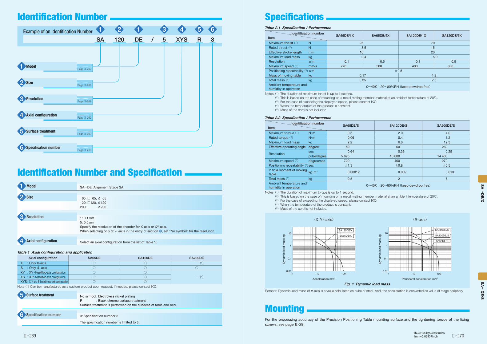
Example of an Identification Number 1 2 1 3 4 5 6
SA 120 DE / 5 XYS R 3
SA…DE: Alignment Stage SA
65: □ 65, φ 65120: □120, φ120200: φ200
1: 0.1μm5: 0.5μmSpecify the resolution of the encoder for X-axis or XY-axis.When selecting only S: θ-axis in the entry of section 4 , set "No symbol" for the resolution.
Select an axial configuration from the list of Table 1.
No symbol : Electroless nickel platingR : Black chrome surface treatmentSurface treatment is performed on the surfaces of table and bed.
3: Specification number 3
The specification number is limited to 3.
Table 1 Axial configuration and applicationAxial configuration SA65DE SA120DE SA200DE
X : Only X-axis ○ ○ -(1)S : Only θ-axis ○ ○ ○XY : XY -based two-axis configuration ○ ○
-(1)XS : Xθ -based two-axis configuration ○ ○XYS : X, Y, and θ-based three-axis configuration ○ ○
Note (1) Can be manufactured as a custom product upon request. If needed, please contact IKO.
Page Ⅱ-269
Page Ⅱ-269
Page Ⅱ-269
Page Ⅱ-269
Page Ⅱ-269
Page Ⅱ-269
Size2
Model1
Axial configuration4
Resolution3
Surface treatment5
Specification number 6
Model1
Size2
Resolution3
Axial configuration4
Surface treatment5
Specification number 6
Table 2.1 Specification / PerformanceIdentification number
ItemSA65DE/1X SA65DE/5X SA120DE/1X SA120DE/5X
Maximum thrust (1) N 25 70Rated thrust (2) N 3.5 15Effective stroke length mm 10 20Maximum load mass kg 2.4 5.9Resolution μm 0.1 0.5 0.1 0.5Maximum speed (3) mm/s 270 500 400 800Positioning repeatability (4)μm ±0.5Mass of moving table kg 0.17 1.2Total mass (5) kg 0.35 2.5Ambient temperature and humidity in operation
0~40℃・20~80%RH (keep dewdrop free)
Notes (1)The duration of maximum thrust is up to 1 second. (2)This is based on the case of mounting on a metal mating member material at an ambient temperature of 20℃. (3)For the case of exceeding the displayed speed, please contact IKO. (4)When the temperature of the product is constant. (5)Mass of the cord is not included.
Table 2.2 Specification / Performance Identification numberItem
SA65DE/S SA120DE/S SA200DE/S
Maximum torque (1) N・m 0.5 2.0 4.0Rated torque (2) N・m 0.06 0.4 1.2Maximum load mass kg 2.2 6.8 12.3Effective operating angle degree 50 60 280
Resolutionsec 0.64 0.36 0.25pulse/degree 5 625 10 000 14 400
Maximum speed (3) degree/sec 720 400 270Positioning repeatability (4)sec ±1.3 ±0.8 ±0.5Inertia moment of moving table
kg・m2 0.00012 0.002 0.013
Total mass (5) kg 0.5 2 6Ambient temperature and humidity in operation
0~40℃・20~80%RH (keep dewdrop free)
Notes (1)The duration of maximum torque is up to 1 second. (2)This is based on the case of mounting on a metal mating member material at an ambient temperature of 20℃. (3)For the case of exceeding the displayed speed, please contact IKO. (4)When the temperature of the product is constant. (5)Mass of the cord is not included.
Fig. 1 Dynamic load mass
Remark: Dynamic load mass of θ-axis is a value calculated as cube of steel. And, the acceleration is converted as value of stage periphery.
Dyn
amic
load
mas
s kg
0.1
0.011 10 100
Acceleration m/s2
〈X(Y)-axis〉
10
1
Dyn
amic
load
mas
s kg
0.1
0.011 10 100
Peripheral acceleration m/s2
〈θ-axis〉
10
1
SA120DE/X
SA65DE/X
SA200DE/S
SA120DE/S
SA65DE/S
Specifications
For the processing accuracy of the Precision Positioning Table mounting surface and the tightening torque of the fixing screws, see page Ⅲ-29.
Mounting
Ⅱ̶269 Ⅱ̶270
SA…
DE
/XS
A…D
E/S
Identification Number and Specification
Identification Number
1N=0.102kgf=0.2248lbs.1mm=0.03937inch
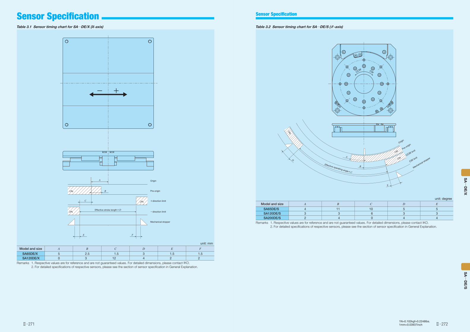
Table 3.1 Sensor timing chart for SA…DE/X (X-axis)
unit: mm
Model and size A B C D E F
SA65DE/X 5 2.5 1.5 3 1.5 1.5SA120DE/X 0 3 12 4 2 2
Remarks 1. Respective values are for reference and are not guaranteed values. For detailed dimensions, please contact IKO. 2. For detailed specifications of respective sensors, please see the section of sensor specification in General Explanation.
+-
Origin
Pre-origin
+direction limit
-direction limit
Mechanical stopper
ON
FE
Effective stroke length+DON
ON
C
B
A
Table 3.2 Sensor timing chart for SA…DE/S (θ-axis)
unit: degree
Model and size A B C D E
SA65DE/S 4 11 10 5 5SA120DE/S 3 3 6 3 3SA200DE/S 2 4 0 4 4
Remarks 1. Respective values are for reference and are not guaranteed values. For detailed dimensions, please contact IKO. 2. For detailed specifications of respective sensors, please see the section of sensor specification in General Explanation.
ON
ON
ON
E
B
AD
CWCCW
Origin
Pre-origin
CCW limit
CW limit
Mechanical stopper
Effective operating angle+C
Sensor Specification
Ⅱ̶271 Ⅱ̶272
SA…
DE
/XS
A…D
E/S
Sensor Specification
1N=0.102kgf=0.2248lbs.1mm=0.03937inchⅡ̶273 Ⅱ̶274
SA…
DE
/XS
A…D
E/S
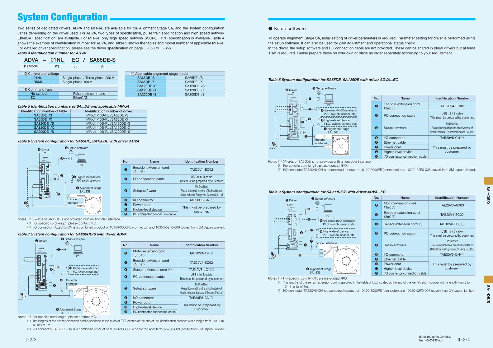
Two series of dedicated drivers, ADVA and MR-J4, are available for the Alignment Stage SA, and the system configuration varies depending on the driver used. For ADVA, two types of specification, pulse train specification and high speed network EtherCAT specification, are available. For MR-J4, only high speed network SSCNET Ⅲ/H specification is available. Table 4 shows the example of identification number for ADVA, and Table 5 shows the tables and model number of applicable MR-J4. For detailed driver specification, please see the driver specification on page Ⅱ-353 to Ⅱ-356.
Table 5 Identification numbers of SA...DE and applicable MR-J4Identification number of table Identification number of driver
SA65DE /S MR-J4-10B-RJ /SA65DE -SSA65DE /X MR-J4-10B-RJ /SA65DE -XSA120DE /S MR-J4-10B-RJ /SA120DE -SSA120DE /X MR-J4-10B-RJ /SA120DE -XSA200DE /S MR-J4-10B-RJ /SA200DE -S
(2) Current and voltage01NL Single-phase / Three-phase 200 VR5ML Single-phase 100 V
(4) Applicable alignment stage modelSA65DE -S SA65DE /SSA65DE -X SA65DE /XSA120DE -S SA120DE /SSA120DE -X SA120DE /XSA200DE -S SA200DE /S
(3) Command typeNo symbol Pulse train commandEC EtherCAT
Table 6 System configuration for SA65DE, SA120DE with driver ADVA
●
●
●
●
●●
❹
●●❺ Setup software
PC
❽ Higher-level device PLC, switch, sensor, etc.
●❼
●●❷ Driver
❻❾
❶ Alignment Stage SA…DE
ACSERVO
ADV Series
Encoderinterface( )1
●❸
No. Name Identification Number
●❸ Encoder extension cord(2m)(2) TAE20V4-EC02
●❹ PC connection cableUSB mini B cable
This must be prepared by customer.
●❺ Setup softwareProDriveNext
Please download from the official website of Hitachi Industrial Equipment Systems Co., Ltd.
●❻ I/O connector TAE20R5-CN(3)●❼ Power cord
This must be prepared by customer.
●❽ Higher-level device●❾ I/O connector connection cable
Notes (1) XY-axis of SA65DE is not provided with an encoder interface.(2) For specific cord length, please contact IKO.(3) I/O connector TAE20R5-CN is a combined product of 10150-3000PE (connector) and 10350-52F0-008 (cover) from 3M Japan Limited.
Table 4 Identification number for ADVA
ADVA – 01NL EC / SA65DE-S(1) Model (2) (3) (4)
Table 7 System configuration for SA200DE/S with driver ADVA
●
●
●●❼ Setup software
PC
PLC, switch, sensor, etc.
●●
●
❾
●❷ Driver
●
❻
❽
❶ Alignment Stage SA…DE
ACSERVO
ADV Series
Encoderinterface
Higher-level device●
●❺
●❹
●❸
No. Name Identification Number
●❸ Motor extension cord(3m)(1) TAE20V3-AM03
●❹ Encoder extension cord(2m)(1) TAE20V4-EC02
●❺ Sensor extension cord (2) TAE10V8-LC□□
●❻ PC connection cableUSB mini B cable
This must be prepared by customer.
●❼ Setup softwareProDriveNext
Please download from the official website of Hitachi Industrial Equipment Systems Co., Ltd.
●❽ I/O connector TAE20R5-CN(3)●❾ Power cord
This must be prepared by customer.
●●� Higher-level device●� I/O connector connection cable
Notes (1) For specific cord length, please contact IKO.(2) The lengths of the sensor extension cord is specified in the fields of □□ located at the end of the identification number with a length from 3 to 10m
in units of 1m.(3) I/O connector TAE20R5-CN is a combined product of 10150-3000PE (connector) and 10350-52F0-008 (cover) from 3M Japan Limited.
Table 8 System configuration for SA65DE, SA120DE with driver ADVA...EC
●
●
●
●
●
●●
❹
●●❺ Setup software
PC
❾ Higher-level device PLC, switch, sensor, etc.
●❽
●●❷ Driver
❻ ❶ Alignment Stage
SA...DE
Encoderinterface( )1
R
ET1
ET2
ACSERVO
ADV Series
❾ Higher-level device (EtherCAT supported device) PLC, switch, sensor, etc.
●❼
●❸
No. Name Identification Number
●❸ Encoder extension cord(2m)(2) TAE20V4-EC02
●❹ PC connection cableUSB mini B cable
This must be prepared by customer.
●❺ Setup softwareProDriveNext
Please download from the official website of Hitachi Industrial Equipment Systems Co., Ltd.
●❻ I/O connector TAE20V5-CN(3)●❼ Ethernet cable
This must be prepared by customer.
●❽ Power cord●❾ Higher-level device●●� I/O connector connection cable
Notes (1) XY-axis of SA65DE is not provided with an encoder interface.(2) For specific cord length, please contact IKO.(3) I/O connector TAE20V5-CN is a combined product of 10120-3000PE (connector) and 10320-52F0-008 (cover) from 3M Japan Limited.
Table 9 System configuration for SA200DE/S with driver ADVA...EC
●
●
●
●
●●❼ Setup software
PC
PLC, switch, sensor, etc.
●
●❷ Driver
●
❻
❽
❶ Alignment Stage SA...DE
Encoder interface
Higher-level device
❺
R
ET1
ET2
ACSERVO
ADV Series
Higher-level device (EtherCAT supported device) PLC, switch, sensor, etc.
●❾
●
●
●❹
●❸
No. Name Identification Number
●❸ Motor extension cord(3m)(1) TAE20V3-AM03
●❹ Encoder extension cord(2m)(1) TAE20V4-EC02
●❺ Sensor extension cord (2) TAE10V8-LC□□
●❻ PC connection cableUSB mini B cable
This must be prepared by customer.
●❼ Setup softwareProDriveNext
Please download from the official website of Hitachi Industrial Equipment Systems Co., Ltd.
●❽ I/O connector TAE20V5-CN(3)●❾ Ethernet cable
This must be prepared by customer.
●●� Power cord●� Higher-level device●� I/O connector connection cable
Notes (1) For specific cord length, please contact IKO.(2) The lengths of the sensor extension cord is specified in the fields of □□ located at the end of the identification number with a length from 3 to
10m in units of 1m.(3) I/O connector TAE20V5-CN is a combined product of 10120-3000PE (connector) and 10320-52F0-008 (cover) from 3M Japan Limited.
● Setup software
To operate Alignment Stage SA, initial setting of driver parameters is required. Parameter setting for driver is performed using the setup software. It can also be used for gain adjustment and operational status check. In the driver, the setup software and PC connection cable are not provided. These can be shared in plural drivers but at least 1 set is required. Please prepare these on your own or place an order separately according to your requirement.
System Configuration
1N=0.102kgf=0.2248lbs.1mm=0.03937inch
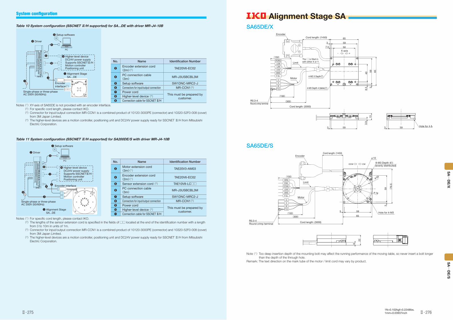
SA65DE/X
SA65DE/S
Note (1) Too deep insertion depth of the mounting bolt may affect the running performance of the moving table, so never insert a bolt longer than the depth of the through hole.
Remark: The text direction on the mark tube of the motor / limit cord may vary by product.
3 59
3.9
15
593 Hole for 4-M3
X-axis
Cord length: (1450)
Cord length: (3000)
(1)4-M3 Depth 4 (table)
(1)4-M2.5 Depth
Encoder
Limit
Motor
Round crimp terminal
- +
65
50
59
65
359
8.5
40
7.5
3
(300)
PORG
+LIM
-LIM
+24V
GND
F.G.
U
V
W
F.G.
(150)
(150)
R0.3-4
□
The □ is filled inwith either X or Y.
Table 11 System configuration (SSCNET Ⅲ/H supported) for SA200DE/S with driver MR-J4-10B
●
●
●
❷ Driver●
●
●
●
●●
❻
❾
❼ Setup software
PC
Single-phase or three-phaseAC 200V (50/60Hz)
Higher-level deviceDC24V power supplySupports SSCNETⅢ/HMotion controllerPositioning unit
❶ Alignment Stage SA...DE
Encoder interface
❽
●❺●❹
●❸
No. Name Identification Number
●❸ Motor extension cord(3m)(1) TAE20V3-AM03
●❹ Encoder extension cord(2m)(1) TAE20V6-EC02
●❺ Sensor extension cord (2) TAE10V8-LC□□
●❻ PC connection cable(3m) MR-J3USBCBL3M
●❼ Setup software SW1DNC-MRC2-J●❽ Connectors for input/output connection MR-CCN1(3)●❾ Power cord
This must be prepared by customer.
●●� Higher-level device (4)●� Connection cable for SSCNET Ⅲ/H
Notes (1) For specific cord length, please contact IKO. (2) The lengths of the sensor extension cord is specified in the fields of □□ located at the end of the identification number with a length
from 3 to 10m in units of 1m. (3) Connector for input/output connection MR-CCN1 is a combined product of 10120-3000PE (connector) and 10320-52F0-008 (cover)
from 3M Japan Limited. (4) The higher-level devices are a motion controller, positioning unit and DC24V power supply ready for SSCNET Ⅲ/H from Mitsubishi
Electric Corporation.
Table 10 System configuration (SSCNET Ⅲ/H supported) for SA...DE with driver MR-J4-10B
●
●
●
●●
❷ Driver●
●
●
❼
❻
●❾
❺ Setup software
PC
Single-phase or three-phaseAC 200V (50/60Hz)
❽ Higher-level deviceDC24V power supplySupports SSCNETⅢ/HMotion controllerPositioning unit
❹
❶ Alignment Stage SA…DE
Encoderinterface( )1
●❸
No. Name Identification Number
●●❸ Encoder extension cord(2m)(2) TAE20V6-EC02
●●❹ PC connection cable(3m) MR-J3USBCBL3M
●❺ Setup software SW1DNC-MRC2-J●❻ Connectors for input/output connection MR-CCN1(3)●●❼ Power cord
This must be prepared by customer.
●❽ Higher-level device (4)●❾ Connection cable for SSCNET Ⅲ/H
Notes (1) XY-axis of SA65DE is not provided with an encoder interface. (2) For specific cord length, please contact IKO. (3) Connector for input/output connection MR-CCN1 is a combined product of 10120-3000PE (connector) and 10320-52F0-008 (cover)
from 3M Japan Limited. (4) The higher-level devices are a motion controller, positioning unit and DC24V power supply ready for SSCNET Ⅲ/H from Mitsubishi
Electric Corporation.
System configuration
6
22
φ59
φ18
Cord length: (1450)
Cord length: (3000)
φ10
8-M3 Depth 4(1)(evenly distributed)
Encoder
Hole for 4-M3
Limit
Motor
R0.3-4Round crimp terminal
ccw cw
(76
.5)
359
3 59
65
U
V
W
F.G.
(300)(150)
(150)ORG
CWL
CCWL
+24V
GND
F.G.
S
Ⅱ̶275 Ⅱ̶276
SA…
DE
/XS
A…D
E/S
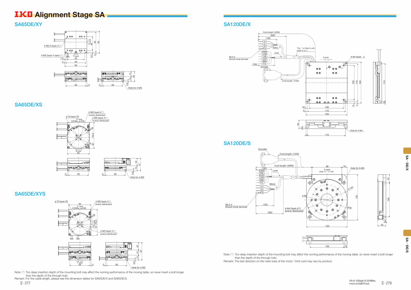
Alignment Stage SA
1N=0.102kgf=0.2248lbs.1mm=0.03937inch
SA65DE/XY
SA65DE/XS
SA65DE/XYS
Note (1) Too deep insertion depth of the mounting bolt may affect the running performance of the moving table, so never insert a bolt longer than the depth of the through hole.
Remark: For the cable length, please see the dimension tables for SA65DE/X and SA65DE/S.
X-a
xis
Y-axis
4-M2.5 Depth 4(1)
4-M3 Depth 4(table)(1)
6559
408.
5 3
50
593
7.5
65
5959 33
1515
30
3.9
Hole for 4-M3
X-axis
θ-axisCCW CW
4-M3 Depth 4(1)
4-M3 Depth 4(1)(evenly distributed)
φ10 Depth 20
φ59
φ18
Hole for 4-M3593
65
37
2215
3.9
(76
.5)
(evenly distributed)
593
CCW CW
4-M3 Depth 4(1)(evenly distributed)
φ59
φ18
φ10 Depth 2065
(76
.5)
θ-axis
X-a
xis
(evenly distributed)4-M3 Depth 4(1)
3.9
1515
22
52
59 593 3Hole for 4-M3
Y-axis
SA120DE/X
SA120DE/S
Note (1) Too deep insertion depth of the mounting bolt may affect the running performance of the moving table, so never insert a bolt longer than the depth of the through hole.
Remark: The text direction on the mark tube of the motor / limit cord may vary by product.
Cord length: (3000)
Cord length: (1450)
X-axis
Motor
Limit
R0.3-4Round crimp terminal
(1)8-M4 Depth
Hole for 4-M4
Encoder
(300)
UVW
F.G.
PORG+LIM-LIM+24VGNDF.G.
(150)
(150)
- +
5 110
25
120
1105
10 100
120
110
100
511
0
5
□
The □ is filled in witheither X or Y.
510
θ-axis
Cord length: (1450)
Cord length: (3000)
8-M4 Depth 8(evenly distributed)
Hole for 4-M4
Encoder
Limit
Motor
R0.3-4Round crimp terminal (1)
ccw cw
120
135φ36
φ120
φ90
2510
0
4
25
10100
88 16
(300)
(150)
(150)PORGCWL
CCWL+24VGNDF.G.
UVW
F.G.
S
Ⅱ̶277 Ⅱ̶278
SA…
DE
/XS
A…D
E/S
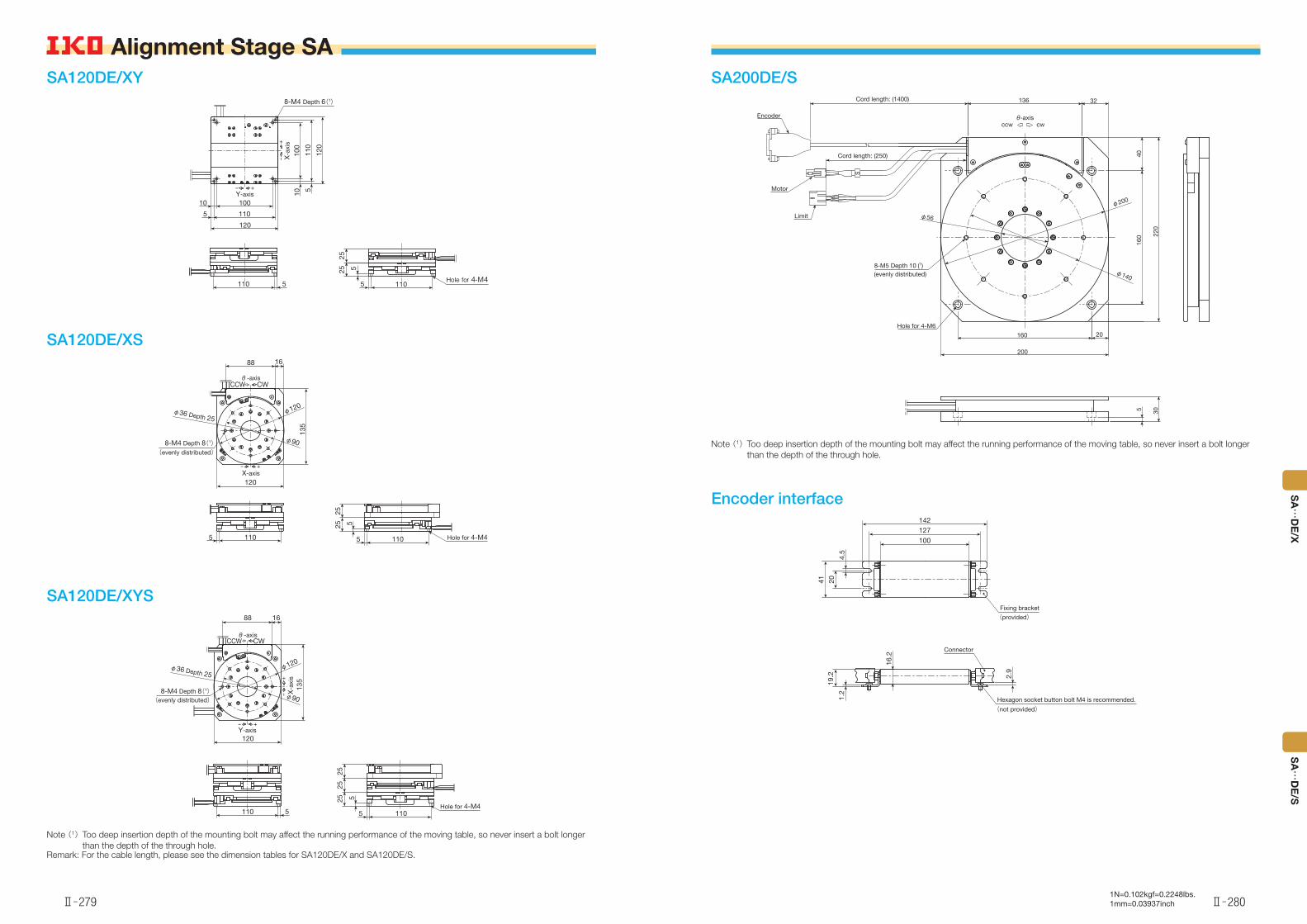
Alignment Stage SA
1N=0.102kgf=0.2248lbs.1mm=0.03937inch
SA120DE/XY
SA120DE/XS
SA120DE/XYS
Note (1) Too deep insertion depth of the mounting bolt may affect the running performance of the moving table, so never insert a bolt longer than the depth of the through hole.
Remark: For the cable length, please see the dimension tables for SA120DE/X and SA120DE/S.
Hole for 4-M45 110
2525
5
110
120
110
100
5
5
10
51010
0
110
120
8-M4 Depth 6(1)
X-a
xis
Y-axis
Hole for 4-M45 110
2525 5
8-M4 Depth 8(1)(evenly distributed)
φ36 Depth 25
θ-axis
X-axis
φ90
φ120
88
120
1105
CCW CW
16
135
8-M4 Depth 8(1)(evenly distributed)
φ36 Depth 25
φ90
φ120
θ-axis
Y-axis
Hole for 4-M4
88
120
110 5 5 110
CCW CW
16
135
2525
25 5
X-a
xis
SA200DE/S
Note (1) Too deep insertion depth of the mounting bolt may affect the running performance of the moving table, so never insert a bolt longer than the depth of the through hole.
ccw cwθ-axis
200
160
220
160
40
20
136
305
32
φ200
φ140
φ56
Cord length: (1400)
Cord length: (250)
8-M5 Depth 10(evenly distributed)
Hole for 4-M6
Limit
Motor
Encoder
(1)
S
Encoder interface
Hexagon socket button bolt M4 is recommended.
(not provided)
(provided)Fixing bracket
142127100
4.5
204119
.2
16.2
1.2
2.9
Connector
Ⅱ̶279 Ⅱ̶280
SA…
DE
/XS
A…D
E/S
Alignment Stage SA