S1 - matsolutions.com documents/Agilent... · connected to an electrical protective earth ... will...
94
S S1 Agilent 81101A 50 MHz Pulse Generator Quick Start Guide
Transcript of S1 - matsolutions.com documents/Agilent... · connected to an electrical protective earth ... will...

S
Agilent 81101A 50 MHz Pulse GeneratorQuick Start Guide
S1
Per 1.000 µµµµs Normal
OUTPUT TRG-LEVLIMITSMODE/TRG
OFF
Delay
1 0ps
WidthLeadETraiE
100.0ns 5.00ns =LeadE
OffsetAmplit
+0.0mV 1.00V
50ΩΩΩΩ into 50.0 ΩΩΩΩ
*OFF ON
MODIFY
MORE
GRAPH
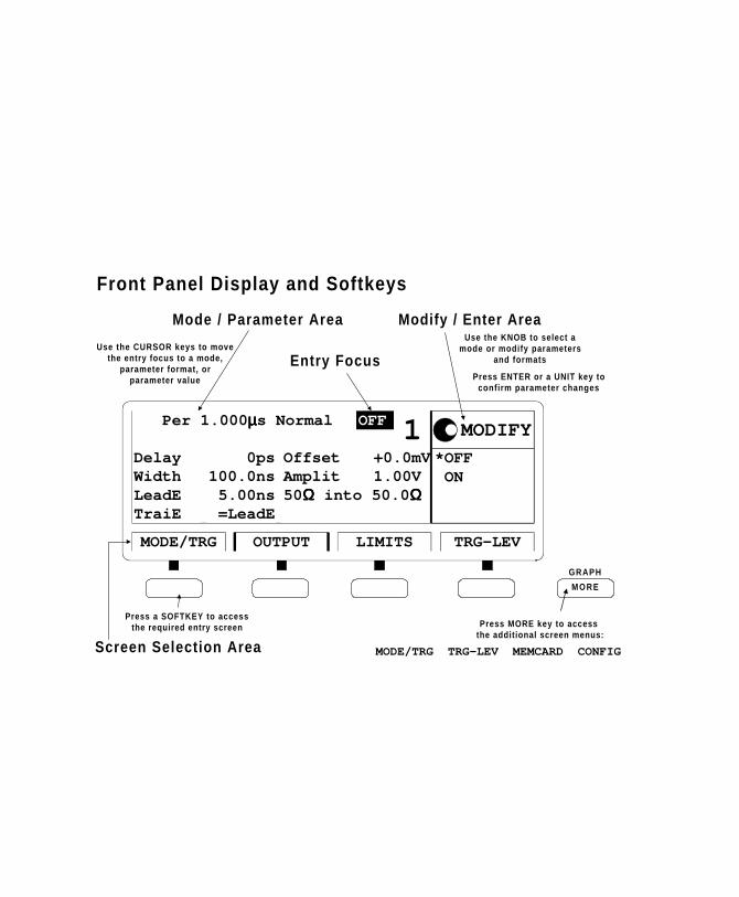
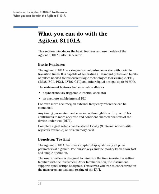
Use the KNOB to select amode or modify parameters
and formats
Press ENTER or a UNIT key toconfirm parameter changes
Use the CURSOR keys to movethe entry focus to a mode,
parameter format, orparameter value
Press a SOFTKEY to accessthe required entry screen Press MORE key to access
the addit ional screen menus:
MODE/TRG TRG-LEV MEMCARD CONFIGScreen Selection Area
Mode / Parameter Area Modify / Enter Area
Entry Focus
Front Panel Display and Softkeys

Quick Start Guide
Agilent 81101A 50 MHz
Pulse Generator
Part No. 81101-91020Printed in Germany March 2000
Edition 1.1, E0300
Notice
Notice
Copyright
1998 Agilent Technologies 1998, 2000. All rights reserved.
No part of this manual may be reproduced in any form or by any means
(including electronic storage and retrieval or translation into a foreign
language) without prior agreement and written consent from Agilent
Technologies Inc. as governed by United States and international
copyright laws.
Notice
The material contained in this document is subject to change without
notice. Agilent Technologies makes no warranty of any kind with regard
to this material, including, but not limited to, the implied warranties of
merchantability and fitness for a particular purpose. Agilent
Technologies shall not be liable for errors contained herein or for
incidental or consequential damages in connection with the furnishing,
performance, or use of this material.
Warranty
This Agilent Technologies product has a warranty against defects in
material and workmanship for a period of three years from date of
shipment. During the warranty period, Agilent Technologies will, at its
option, either repair or replace products that prove to be defective. For
warranty service or repair, this product must be returned to a service
facility designated by Agilent Technologies. The Buyer shall pay Agilent
Technologies round-trip travel expenses. For products returned to
Agilent Technologies for warranty service, the Buyer shall prepay
shipping charges to Agilent Technologies and Agilent Technologies shall
pay shipping charges to return the product to the Buyer. However, the
Buyer shall pay all shipping charges, duties and taxes for products
returned to Agilent Technologies from another country.
4
Notice
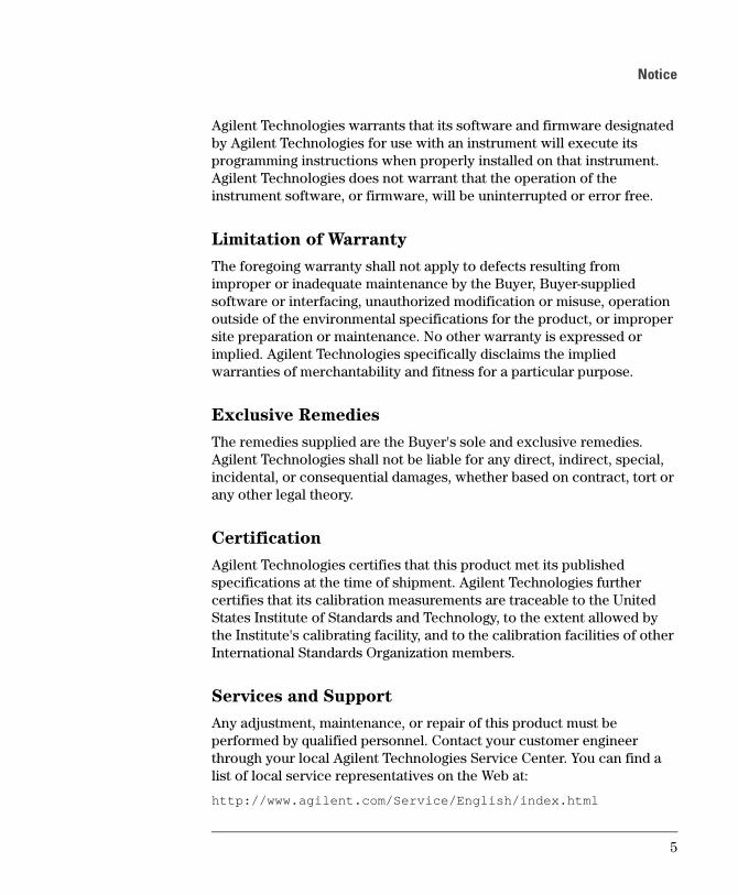
Agilent Technologies warrants that its software and firmware designated
by Agilent Technologies for use with an instrument will execute its
programming instructions when properly installed on that instrument.
Agilent Technologies does not warrant that the operation of the
instrument software, or firmware, will be uninterrupted or error free.
Limitation of Warranty
The foregoing warranty shall not apply to defects resulting from
improper or inadequate maintenance by the Buyer, Buyer-supplied
software or interfacing, unauthorized modification or misuse, operation
outside of the environmental specifications for the product, or improper
site preparation or maintenance. No other warranty is expressed or
implied. Agilent Technologies specifically disclaims the implied
warranties of merchantability and fitness for a particular purpose.
Exclusive Remedies
The remedies supplied are the Buyer's sole and exclusive remedies.
Agilent Technologies shall not be liable for any direct, indirect, special,
incidental, or consequential damages, whether based on contract, tort or
any other legal theory.
Certification
Agilent Technologies certifies that this product met its published
specifications at the time of shipment. Agilent Technologies further
certifies that its calibration measurements are traceable to the United
States Institute of Standards and Technology, to the extent allowed by
the Institute's calibrating facility, and to the calibration facilities of other
International Standards Organization members.
Services and Support
Any adjustment, maintenance, or repair of this product must be
performed by qualified personnel. Contact your customer engineer
through your local Agilent Technologies Service Center. You can find a
list of local service representatives on the Web at:
http://www.agilent.com/Service/English/index.html
5
Safety Summary
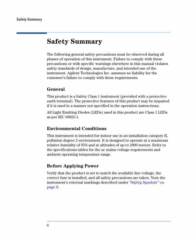
Safety Summary
The following general safety precautions must be observed during all
phases of operation of this instrument. Failure to comply with these
precautions or with specific warnings elsewhere in this manual violates
safety standards of design, manufacture, and intended use of the
instrument. Agilent Technologies Inc. assumes no liability for the
customer's failure to comply with these requirements.
General
This product is a Safety Class 1 instrument (provided with a protective
earth terminal). The protective features of this product may be impaired
if it is used in a manner not specified in the operation instructions.
All Light Emitting Diodes (LEDs) used in this product are Class 1 LEDs
as per IEC 60825-1.
Environmental Conditions
This instrument is intended for indoor use in an installation category II,
pollution degree 2 environment. It is designed to operate at a maximum
relative humidity of 95% and at altitudes of up to 2000 meters. Refer to
the specifications tables for the ac mains voltage requirements and
ambient operating temperature range.
Before Applying Power
Verify that the product is set to match the available line voltage, the
correct fuse is installed, and all safety precautions are taken. Note the
instrument's external markings described under Safety Symbols on
page 8.
6
Safety Summary
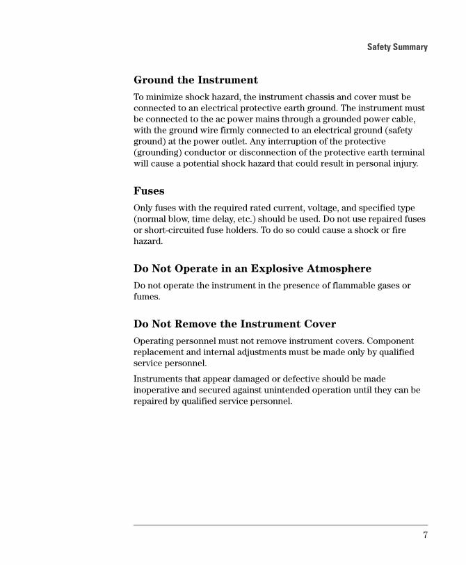
Ground the Instrument
To minimize shock hazard, the instrument chassis and cover must be
connected to an electrical protective earth ground. The instrument must
be connected to the ac power mains through a grounded power cable,
with the ground wire firmly connected to an electrical ground (safety
ground) at the power outlet. Any interruption of the protective
(grounding) conductor or disconnection of the protective earth terminal
will cause a potential shock hazard that could result in personal injury.
Fuses
Only fuses with the required rated current, voltage, and specified type
(normal blow, time delay, etc.) should be used. Do not use repaired fuses
or short-circuited fuse holders. To do so could cause a shock or fire
hazard.
Do Not Operate in an Explosive Atmosphere
Do not operate the instrument in the presence of flammable gases or
fumes.
Do Not Remove the Instrument Cover
Operating personnel must not remove instrument covers. Component
replacement and internal adjustments must be made only by qualified
service personnel.
Instruments that appear damaged or defective should be made
inoperative and secured against unintended operation until they can be
repaired by qualified service personnel.
7

Safety Summary
Safety Symbols
Caution (refer to accompanying documents)
Protective earth (ground) terminal
In the manuals:
WA RNING The WARNING sign denotes a hazard. It calls attention to a
procedure, practice, or the like, which, if not correctly performed
or adhered to, could result in personal injury. Do not proceed
beyond a WARNING sign until the indicated conditions are fully
understood and met.
CA UTIO N The CAUTION sign denotes a hazard. It calls attention to an operating
procedure, or the like, which, if not correctly performed or adhered to,
could result in damage to or destruction of part or all of the product. Do
not proceed beyond a CAUTION sign until the indicated conditions are
fully understood and met.
8
About this Book
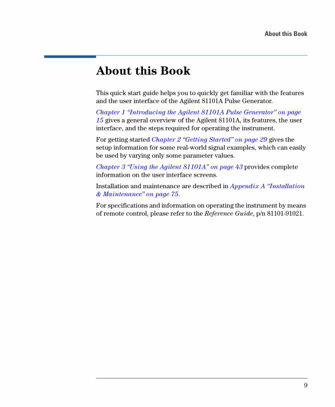
About this Book
This quick start guide helps you to quickly get familiar with the features
and the user interface of the Agilent 81101A Pulse Generator.
Chapter 1 Introducing the Agilent 81101A Pulse Generator on page
15 gives a general overview of the Agilent 81101A, its features, the user
interface, and the steps required for operating the instrument.
For getting started Chapter 2 Getting Started on page 29 gives the
setup information for some real-world signal examples, which can easily
be used by varying only some parameter values.
Chapter 3 Using the Agilent 81101A on page 43 provides complete
information on the user interface screens.
Installation and maintenance are described in Appendix A Installation
& Maintenance on page 75.
For specifications and information on operating the instrument by means
of remote control, please refer to the Reference Guide, p/n 81101-91021.
9
About this Book
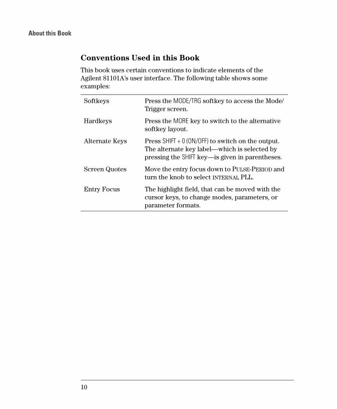
Conventions Used in this Book
This book uses certain conventions to indicate elements of the
Agilent 81101As user interface. The following table shows some
examples:
Softkeys Press the MODE/TRG softkey to access the Mode/
Trigger screen.
Hardkeys Press the MORE key to switch to the alternative
softkey layout.
Alternate Keys Press SHIFT + 0 (ON/OFF) to switch on the output.
The alternate key labelwhich is selected by
pressing the SHIFT keyis given in parentheses.
Screen Quotes Move the entry focus down to PULSE-PERIOD and
turn the knob to select INTERNAL PLL.
Entry Focus The highlight field, that can be moved with the
cursor keys, to change modes, parameters, or
parameter formats.
10
Contents
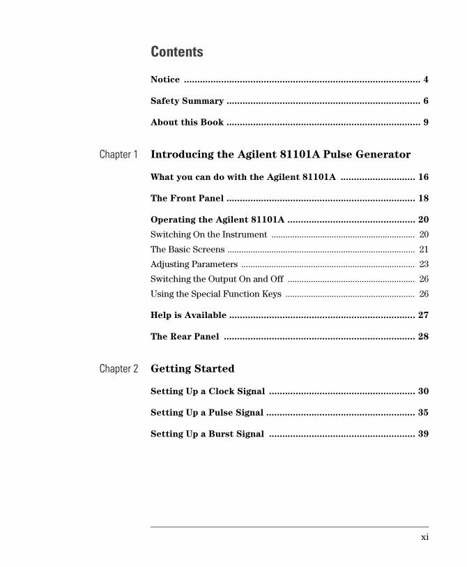
Notice ......................................................................................... 4
Safety Summary ......................................................................... 6
About this Book ......................................................................... 9
Chapter 1 Introducing the Agilent 81101A Pulse Generator
What you can do with the Agilent 81101A ............................ 16
The Front Panel ....................................................................... 18
Operating the Agilent 81101A ................................................ 20
Switching On the Instrument .............................................................. 20
The Basic Screens ................................................................................. 21
Adjusting Parameters ........................................................................... 23
Switching the Output On and Off ....................................................... 26
Using the Special Function Keys ........................................................ 26
Help is Available ...................................................................... 27
The Rear Panel ........................................................................ 28
Chapter 2 Getting Started
Setting Up a Clock Signal ....................................................... 30
Setting Up a Pulse Signal ........................................................ 35
Setting Up a Burst Signal ....................................................... 39
xi
Contents
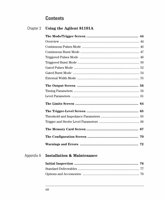
Chapter 3 Using the Agilent 81101A
The Mode/Trigger Screen ....................................................... 44
Overview ................................................................................................. 44
Continuous Pulses Mode ...................................................................... 46
Continuous Burst Mode ........................................................................ 47
Triggered Pulses Mode ......................................................................... 48
Triggered Burst Mode ........................................................................... 50
Gated Pulses Mode ................................................................................ 52
Gated Burst Mode ................................................................................. 54
External Width Mode ............................................................................ 55
The Output Screen ................................................................. 56
Timing Parameters ................................................................................ 56
Level Parameters ................................................................................... 61
The Limits Screen ................................................................... 64
The Trigger-Level Screen ....................................................... 65
Threshold and Impedance Parameters ............................................... 65
Trigger and Strobe Level Parameters ................................................. 66
The Memory Card Screen ....................................................... 67
The Configuration Screen ...................................................... 70
Warnings and Errors .............................................................. 72
Appendix A Installation & Maintenance
Initial Inspection .................................................................... 76
Standard Deliverables ........................................................................... 77
Options and Accessories: ..................................................................... 78
xii
Contents
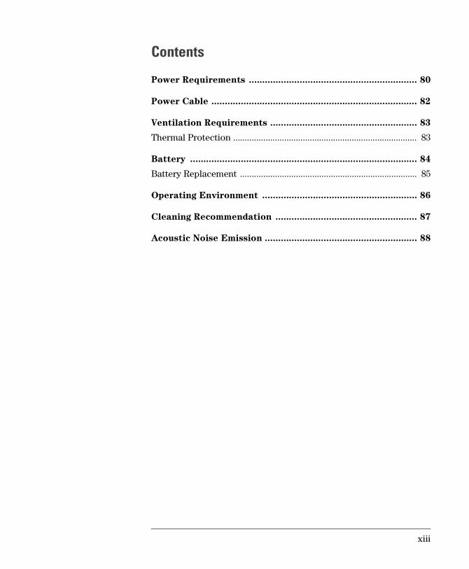
Power Requirements ............................................................... 80
Power Cable ............................................................................. 82
Ventilation Requirements ....................................................... 83
Thermal Protection ............................................................................... 83
Battery ..................................................................................... 84
Battery Replacement ............................................................................ 85
Operating Environment .......................................................... 86
Cleaning Recommendation ..................................................... 87
Acoustic Noise Emission ......................................................... 88
xiii

Contents
xiv

11Introducing the
Agilent 81101A Pulse
Generator
The purpose of the introduction chapter is to give a general overview of
the Agilent 81101A.
The main features and use models are described in What you can do
with the Agilent 81101A on page 16.
Operating the instrument via the front panel user interface is described in
The Front Panel on page 18 and Operating the Agilent 81101A on
page 20.
Help is Available on page 27 shortly introduces the Agilent 81101As
on-line help system.
Finally, The Rear Panel on page 28 takes a look at the back of the
Agilent 81101A.
15
Introducing the Agilent 81101A Pulse GeneratorWhat you can do with the Agilent 81101A
What you can do with the
Agilent 81101A
This section introduces the basic features and use models of the
Agilent 81101A Pulse Generator.
Basic Features
The Agilent 81101A is a single-channel pulse generator with variable
transition times. It is capable of generating all standard pulses and bursts
of pulses needed to test current logic technologies (for example, TTL,
CMOS, ECL, PECL, LVDS, GTL) and other digital designs up to 50 MHz.
The instrument features two internal oscillators:
a synchronously triggerable internal oscillator
an accurate, stable internal PLL
For even more accuracy, an external frequency reference can be
connected.
Any timing parameter can be varied without glitch or drop out. This
contributes to more accurate and confident characterizations of the
device under test (DUT).
Complete signal setups can be stored locally (9 internal non-volatile
registers available) or on a memory card.
Benchtop Testing
The Agilent 81101A features a graphic display showing all pulse
parameters at a glance. The cursor keys and the modify knob allow fast
and simple operation.
The user interface is designed to minimize the time invested in getting
familiar with the instrument. After familiarization, the instrument
supports quick setups of signals. This leaves you free to concentrate on
the measurement task and testing of the DUT.
16
Introducing the Agilent 81101A Pulse GeneratorWhat you can do with the Agilent 81101A
Automated Testing
The Agilent 81101A features an GP-IB/SCPI-conform command structure
for all features. Using this programming interface, the instrument can be
easily integrated into all phases of test system development such as
planning rack integration and test program generation.
Programs designed for the Agilent 81101A are compatible with all other
models of the Agilent 81100 family.
NOTE For a command reference list, please refer to the Reference Guide, part
number 81101-91021.
17
Introducing the Agilent 81101A Pulse GeneratorThe Front Panel
The Front Panel
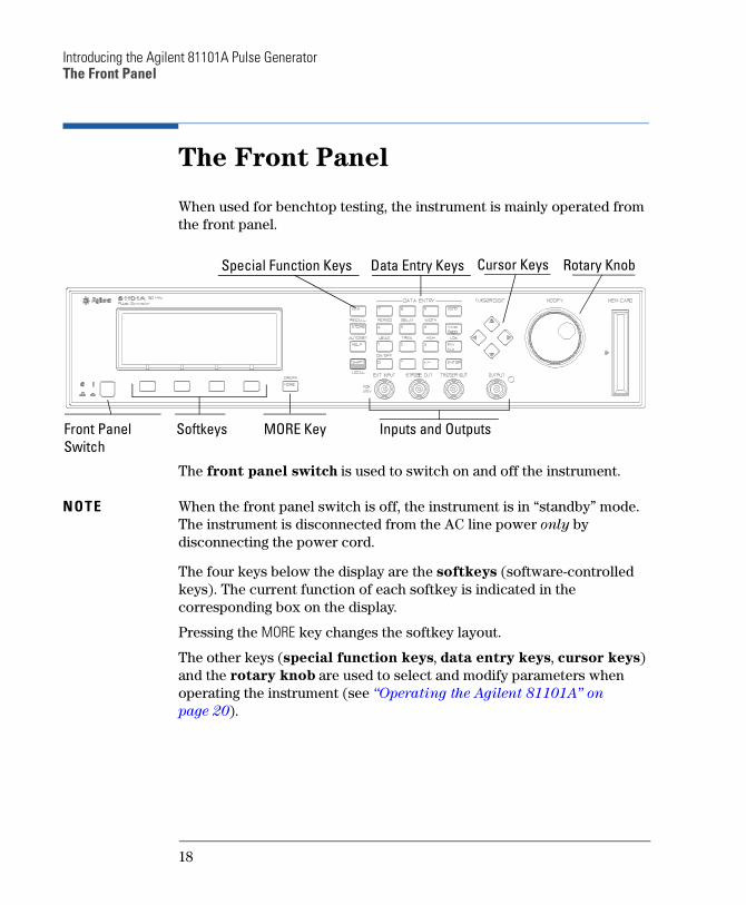
When used for benchtop testing, the instrument is mainly operated from
the front panel.
The front panel switch is used to switch on and off the instrument.
NOTE When the front panel switch is off, the instrument is in standby mode.
The instrument is disconnected from the AC line power only by
disconnecting the power cord.
The four keys below the display are the softkeys (software-controlled
keys). The current function of each softkey is indicated in the
corresponding box on the display.
Pressing the MORE key changes the softkey layout.
The other keys (special function keys, data entry keys, cursor keys)
and the rotary knob are used to select and modify parameters when
operating the instrument (see Operating the Agilent 81101A on
page 20).
Special Function Keys Data Entry Keys Cursor Keys Rotary Knob
Front PanelSwitch
Softkeys MORE Key Inputs and Outputs
18
Introducing the Agilent 81101A Pulse GeneratorThe Front Panel
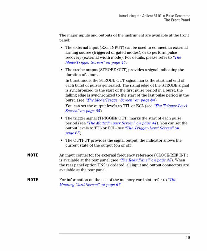
The major inputs and outputs of the instrument are available at the front
panel:
The external input (EXT INPUT) can be used to connect an external
arming source (triggered or gated modes), or to perform pulse
recovery (external width mode). For details, please refer to The
Mode/Trigger Screen on page 44.
The strobe output (STROBE OUT) provides a signal indicating the
duration of a burst.
In burst mode, the STROBE OUT signal marks the start and end of
each burst of pulses generated. The rising edge of the STROBE signal
is synchronized to the start of the first pulse period in a burst, the
falling edge is synchronized to the start of the last pulse period in the
burst. (see The Mode/Trigger Screen on page 44).
You can set the output levels to TTL or ECL (see The Trigger-Level
Screen on page 65)
The trigger signal (TRIGGER OUT) marks the start of each pulse
period (see The Mode/Trigger Screen on page 44). You can set the
output levels to TTL or ECL (see The Trigger-Level Screen on
page 65).
The OUTPUT provides the signal output, the indicator shows the
current state of the output (on or off).
NOTE An input connector for external frequency reference (CLOCK/REF INP.)
is available at the rear panel (see The Rear Panel on page 28). When
the rear panel option UN2 is ordered, all input and output connectors are
available at the rear panel.
NOTE For information on the use of the memory card slot, refer to The
Memory Card Screen on page 67.
19
Introducing the Agilent 81101A Pulse GeneratorOperating the Agilent 81101A
Operating the Agilent 81101A
This section guides you through the first steps when operating the
Agilent 81101A via the user interface.
NOTE For information on operating the Agilent 81101A via remote control,
please refer to the Reference Guide, part number 81101-91021.
Switching On the Instrument
After switching on the instrument the display indicates that the
instrument selftest is running. This can take several seconds to complete.
If the selftest fails, you see a flashing E at the bottom of the screen. Press
the HELP key to see a list of the selftest error messages. Use the knob or
the cursor keys to scroll through the list if necessary.
To return to normal operation press HELP again. Note that the selftest
error messages are removed from the error queue after this.
20
Introducing the Agilent 81101A Pulse GeneratorOperating the Agilent 81101A
The Basic Screens
The major parameters for pulse generation can be set up in only two
screens.
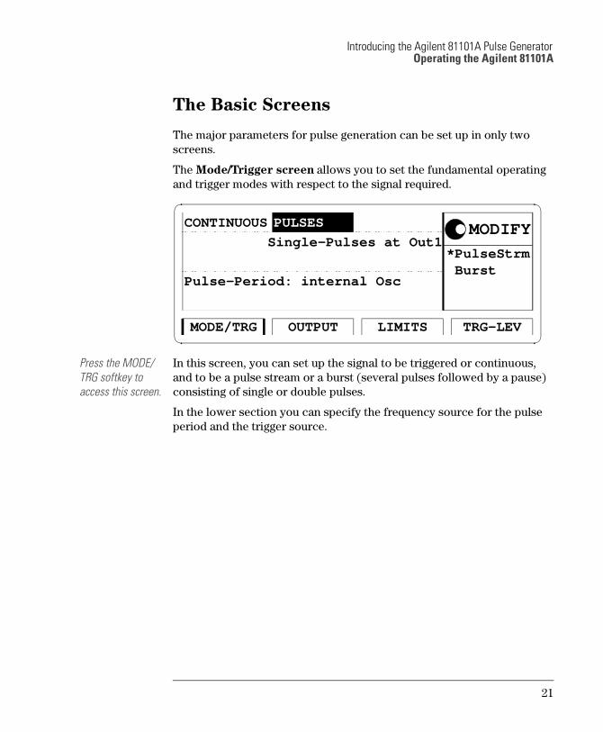
The Mode/Trigger screen allows you to set the fundamental operating
and trigger modes with respect to the signal required.
Press the MODE/TRG softkey to access this screen.
In this screen, you can set up the signal to be triggered or continuous,
and to be a pulse stream or a burst (several pulses followed by a pause)
consisting of single or double pulses.
In the lower section you can specify the frequency source for the pulse
period and the trigger source.
*PulseStrm Burst
OUTPUT TRG-LEVLIMITSMODE/TRG
CONTINUOUS
Single-Pulses at Out1
Pulse-Period: internal Osc
MODIFYPULSES
21
Introducing the Agilent 81101A Pulse GeneratorOperating the Agilent 81101A
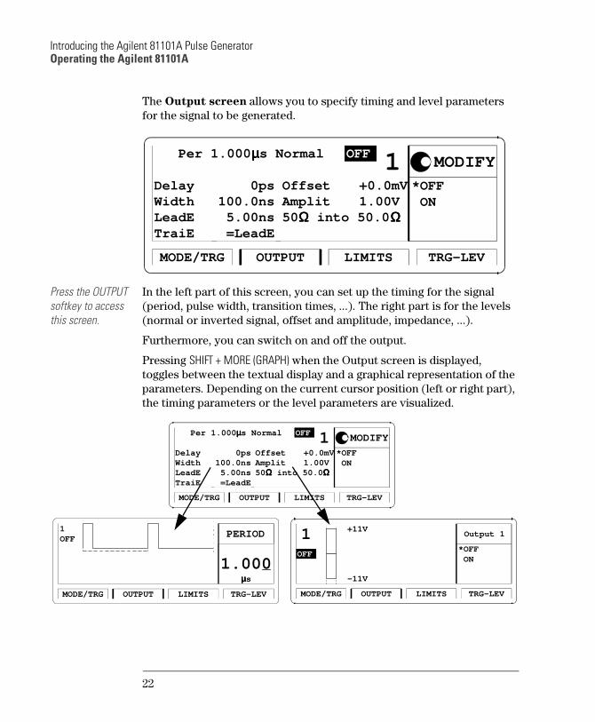
The Output screen allows you to specify timing and level parameters
for the signal to be generated.
Press the OUTPUT softkey to access this screen.
In the left part of this screen, you can set up the timing for the signal
(period, pulse width, transition times, ...). The right part is for the levels
(normal or inverted signal, offset and amplitude, impedance, ...).
Furthermore, you can switch on and off the output.
Pressing SHIFT + MORE (GRAPH) when the Output screen is displayed,
toggles between the textual display and a graphical representation of the
parameters. Depending on the current cursor position (left or right part),
the timing parameters or the level parameters are visualized.
Per 1.000 µµµµs Normal
OUTPUT TRG-LEVLIMITSMODE/TRG
OFF
Delay
1 0ps
WidthLeadETraiE
100.0ns 5.00ns =LeadE
OffsetAmplit
+0.0mV 1.00V
50ΩΩΩΩ into 50.0 ΩΩΩΩ
*OFF ON
MODIFY
*OFF ON
OUTPUT TRG-LEVLIMITSMODE/TRG
1 +11V
-11V
Output 1
OFF
µµµµs
1.000
OUTPUT TRG-LEVLIMITSMODE/TRG
1OFF PERIOD
Per 1.000 µµµµs Normal
OUTPUT TRG-LEVLIMITSMODE/TRG
OFF
Delay
1 0ps
WidthLeadETraiE
100.0ns 5.00ns =LeadE
OffsetAmplit
+0.0mV 1.00V
50ΩΩΩΩ into 50.0 ΩΩΩΩ
*OFF ON
MODIFY
22
Introducing the Agilent 81101A Pulse GeneratorOperating the Agilent 81101A
Adjusting Parameters
Adjusting parameters within a screen, requires two steps:
selecting the parameter
adjusting its value
Some parameters allow different formats of their values. For example,
the pulse width can be displayed and entered as an absolute value, as
duty cycle (percentage of the period), or as the delay of the trailing edge.
The following sections show the standard procedure for adjusting
parameters, and list some features useful for the advanced user.
Standard Procedure
To experience the standard procedure for adjusting parameters, consider
the following example where the duty cycle is set to 50%.
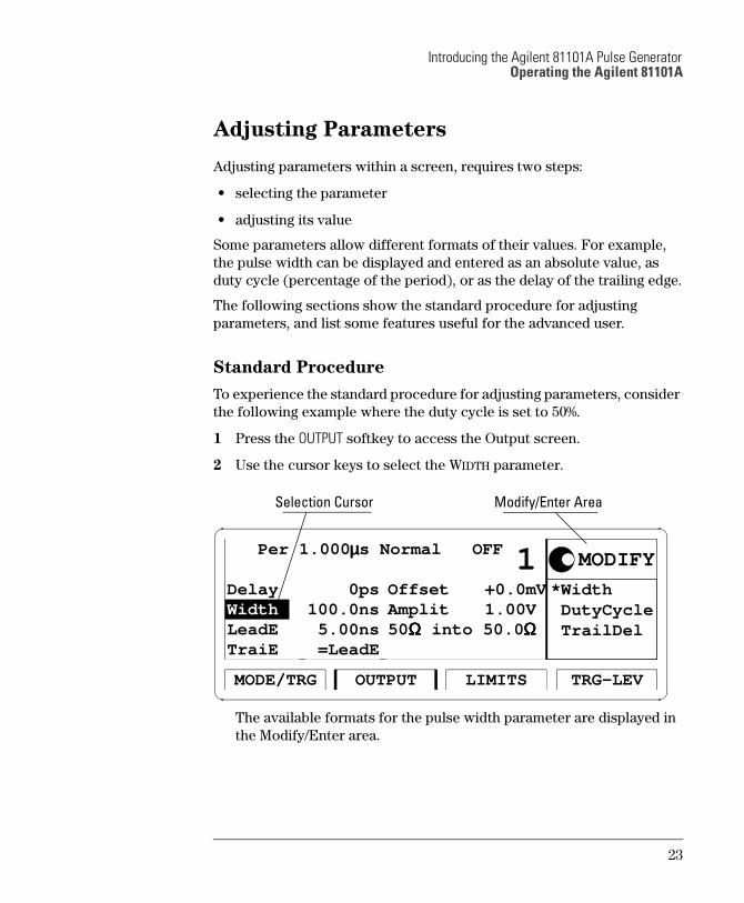
1 Press the OUTPUT softkey to access the Output screen.
2 Use the cursor keys to select the WIDTH parameter.
The available formats for the pulse width parameter are displayed in
the Modify/Enter area.
*Width DutyCycle TrailDel
Per 1.000 µµµµs Normal OFF
OUTPUT TRG-LEVLIMITSMODE/TRG
Delay
1 0ps
LeadETraiE
100.0ns 5.00ns =LeadE
OffsetAmplit
+0.0mV 1.00V
50ΩΩΩΩ into 50.0 ΩΩΩΩ
MODIFY
Width
Selection Cursor Modify/Enter Area
23
Introducing the Agilent 81101A Pulse GeneratorOperating the Agilent 81101A
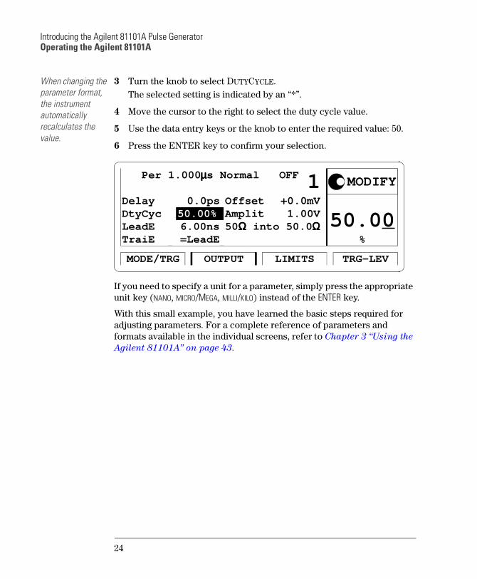
When changing the parameter format, the instrument automatically recalculates the value.
3 Turn the knob to select DUTYCYCLE.
The selected setting is indicated by an *.
4 Move the cursor to the right to select the duty cycle value.
5 Use the data entry keys or the knob to enter the required value: 50.
6 Press the ENTER key to confirm your selection.
If you need to specify a unit for a parameter, simply press the appropriate
unit key (NANO, MICRO/MEGA, MILLI/KILO) instead of the ENTER key.
With this small example, you have learned the basic steps required for
adjusting parameters. For a complete reference of parameters and
formats available in the individual screens, refer to Chapter 3 Using the
Agilent 81101A on page 43.
%
50.00
OUTPUT TRG-LEVLIMITSMODE/TRG
Delay
1 0.0ps
DtyCycLeadETraiE
50.00%
=LeadE
OffsetAmplit
+0.0mV 1.00V
50ΩΩΩΩ into 50.0 ΩΩΩΩ
MODIFY
6.00ns
Per 1.000 µµµµs Normal OFF
24
Introducing the Agilent 81101A Pulse GeneratorOperating the Agilent 81101A
Advanced Procedures
The following features can be used to make operation more comfortable.
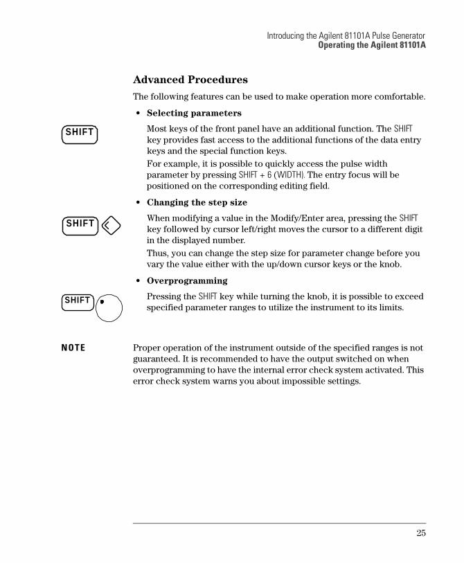
Selecting parameters
Most keys of the front panel have an additional function. The SHIFT
key provides fast access to the additional functions of the data entry
keys and the special function keys.
For example, it is possible to quickly access the pulse width
parameter by pressing SHIFT + 6 (WIDTH). The entry focus will be
positioned on the corresponding editing field.
Changing the step size
When modifying a value in the Modify/Enter area, pressing the SHIFT
key followed by cursor left/right moves the cursor to a different digit
in the displayed number.
Thus, you can change the step size for parameter change before you
vary the value either with the up/down cursor keys or the knob.
Overprogramming
Pressing the SHIFT key while turning the knob, it is possible to exceed
specified parameter ranges to utilize the instrument to its limits.
NOTE Proper operation of the instrument outside of the specified ranges is not
guaranteed. It is recommended to have the output switched on when
overprogramming to have the internal error check system activated. This
error check system warns you about impossible settings.
SHIFT
SHIFT
SHIFT
25
Introducing the Agilent 81101A Pulse GeneratorOperating the Agilent 81101A
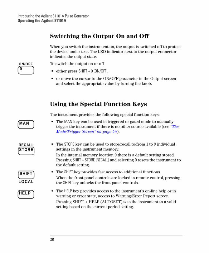
Switching the Output On and Off
When you switch the instrument on, the output is switched off to protect
the device under test. The LED indicator next to the output connector
indicates the output state.
To switch the output on or off
either press SHIFT + 0 (ON/OFF),
or move the cursor to the ON/OFF parameter in the Output screen
and select the appropriate value by turning the knob.
Using the Special Function Keys
The instrument provides the following special function keys:
The MAN key can be used in triggered or gated mode to manually
trigger the instrument if there is no other source available (see The
Mode/Trigger Screen on page 44).
The STORE key can be used to store/recall to/from 1 to 9 individual
settings in the instrument memory.
In the internal memory location 0 there is a default setting stored.
Pressing SHIFT + STORE (RECALL) and selecting 0 resets the instrument to
the default setting.
The SHIFT key provides fast access to additional functions.
When the front panel controls are locked in remote control, pressing
the SHIFT key unlocks the front panel controls.
The HELP key provides access to the instruments on-line help or in
warning or error state, access to Warning/Error Report screen.
Pressing SHIFT + HELP (AUTOSET) sets the instrument to a valid
setting based on the current period setting.
0ON/OFF
MAN
STORERECALL
SHIFT
LOCAL
HELP
26
Introducing the Agilent 81101A Pulse GeneratorHelp is Available
Help is Available
Whenever you are in doubt or the instrument signals warnings or errors,
press the HELP key.
Help If there are no warnings or errors pending, pressing the HELP key
displays information on the currently selected parameter, the parameter
help. More information is available within the help system:
Parameter Help
The help information gives a short description of the parameter or
setting options and the corresponding SCPI command(s) syntax for
programming the parameter or setting.
If there is more than one screen available (indicated by small arrows),
use the knob or the cursor keys to scroll through the help
information.
To access parameter help from other screens of the help system,
press the ON FIELD softkey.
Concept Help
Pressing the CONCEPT softkey within the help system displays a short
description of the instrument.
Serial Numbers and Software Revision
Pressing the SERIAL # softkey within the help system displays
information on serial numbers and software revision codes of the
instrument.
Warnings and Errors
If there are warnings or errors pending (indicated by a flushing W or E),
pressing the HELP key displays a list of the current messages. Using the
ERROR QU and WARNING softkeys, you can toggle between both lists. For
more information on warnings and errors, see Warnings and Errors on
page 72.
Exit Help To exit from the help system, press the HELP key again, or press the EXIT
HELP softkey.
27
Introducing the Agilent 81101A Pulse GeneratorThe Rear Panel
The Rear Panel
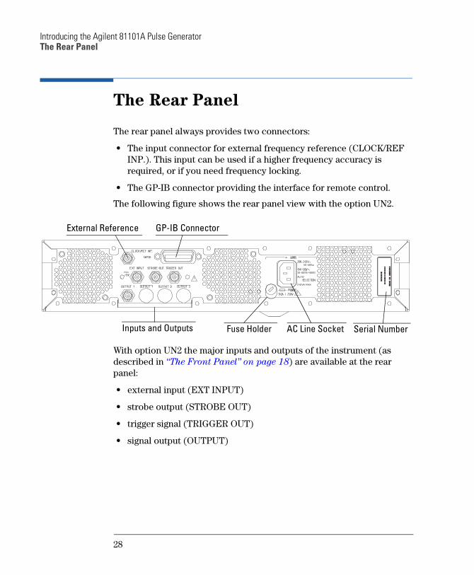
The rear panel always provides two connectors:
The input connector for external frequency reference (CLOCK/REF
INP.). This input can be used if a higher frequency accuracy is
required, or if you need frequency locking.
The GP-IB connector providing the interface for remote control.
The following figure shows the rear panel view with the option UN2.
With option UN2 the major inputs and outputs of the instrument (as
described in The Front Panel on page 18) are available at the rear
panel:
external input (EXT INPUT)
strobe output (STROBE OUT)
trigger signal (TRIGGER OUT)
signal output (OUTPUT)
Inputs and Outputs Fuse Holder AC Line Socket Serial Number
GP-IB ConnectorExternal Reference
28
2 2Getting Started
The intention of this chapter is to give the necessary steps to set up generic signals for first-time users of the Agilent 81101A.
This chapter provides examples for the following types of signals:
“Setting Up a Clock Signal” on page 30
“Setting Up a Pulse Signal” on page 35
“Setting Up a Burst Signal” on page 39
At the end of each example, the required set of device commands is listed to provide programming examples. For further information on the commands and a complete command reference please refer to the Reference Guide, p/n 81101-91021.
The examples are intended to be performed one after the other. Therefore, the first example provides the most detailed instructions, while the other examples are described on a higher level.
29
Getting StartedSetting Up a Clock Signal
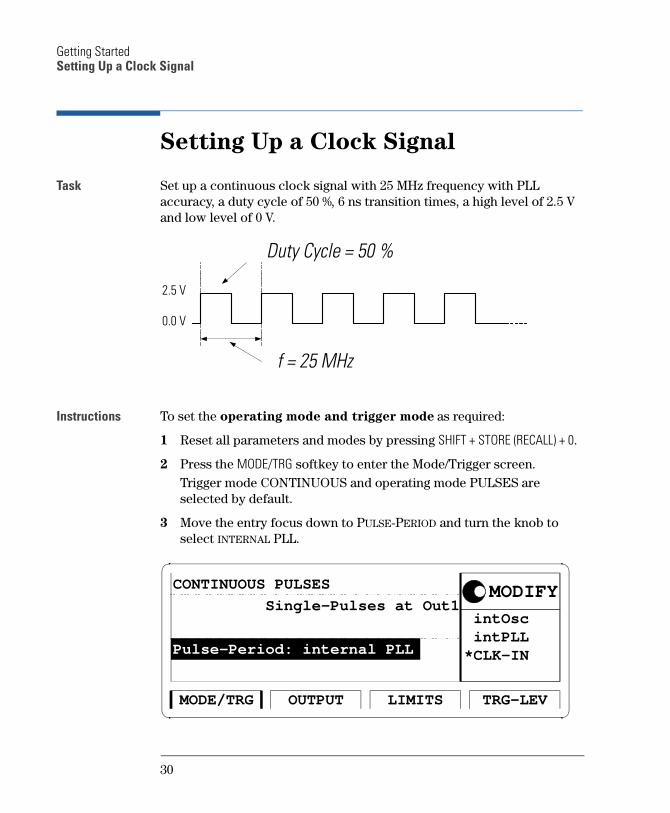
Setting Up a Clock Signal
Task Set up a continuous clock signal with 25 MHz frequency with PLL accuracy, a duty cycle of 50 %, 6 ns transition times, a high level of 2.5 V and low level of 0 V.
Instructions To set the operating mode and trigger mode as required:
1 Reset all parameters and modes by pressing SHIFT + STORE (RECALL) + 0.
2 Press the MODE/TRG softkey to enter the Mode/Trigger screen. Trigger mode CONTINUOUS and operating mode PULSES are selected by default.
3 Move the entry focus down to PULSE-PERIOD and turn the knob to select INTERNAL PLL.
Duty Cycle = 50 %
f = 25 MHz
2.5 V
0.0 V
intOsc intPLL*CLK-IN
OUTPUT TRG-LEVLIMITSMODE/TRG
CONTINUOUS PULSES
Single-Pulses at Out1MODIFY
Pulse-Period: internal PLL
30
Getting StartedSetting Up a Clock Signal
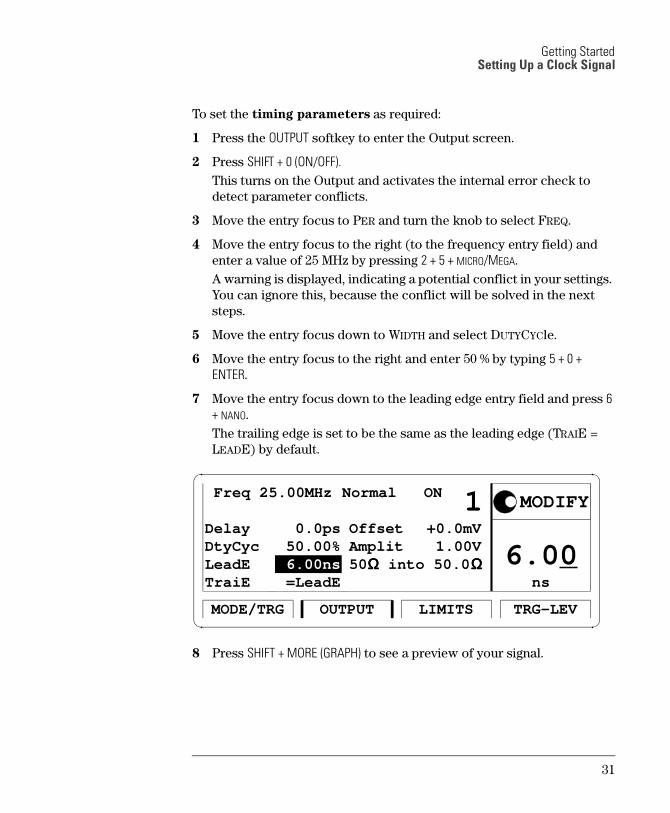
To set the timing parameters as required:
1 Press the OUTPUT softkey to enter the Output screen.
2 Press SHIFT + 0 (ON/OFF).
This turns on the Output and activates the internal error check to detect parameter conflicts.
3 Move the entry focus to PER and turn the knob to select FREQ.
4 Move the entry focus to the right (to the frequency entry field) and enter a value of 25 MHz by pressing 2 + 5 + MICRO/MEGA.A warning is displayed, indicating a potential conflict in your settings. You can ignore this, because the conflict will be solved in the next steps.
5 Move the entry focus down to WIDTH and select DUTYCYCle.
6 Move the entry focus to the right and enter 50 % by typing 5 + 0 +
ENTER.
7 Move the entry focus down to the leading edge entry field and press 6
+ NANO. The trailing edge is set to be the same as the leading edge (TRAIE = LEADE) by default.
8 Press SHIFT + MORE (GRAPH) to see a preview of your signal.
ns
6.00
Freq 25.00MHz Normal ON
OUTPUT TRG-LEVLIMITSMODE/TRG
Delay
1 0.0ps
DtyCycLeadETraiE
50.00% 6.00ns =LeadE
OffsetAmplit
+0.0mV 1.00V
50ΩΩΩΩ into 50.0 ΩΩΩΩ
MODIFY
31
Getting StartedSetting Up a Clock Signal
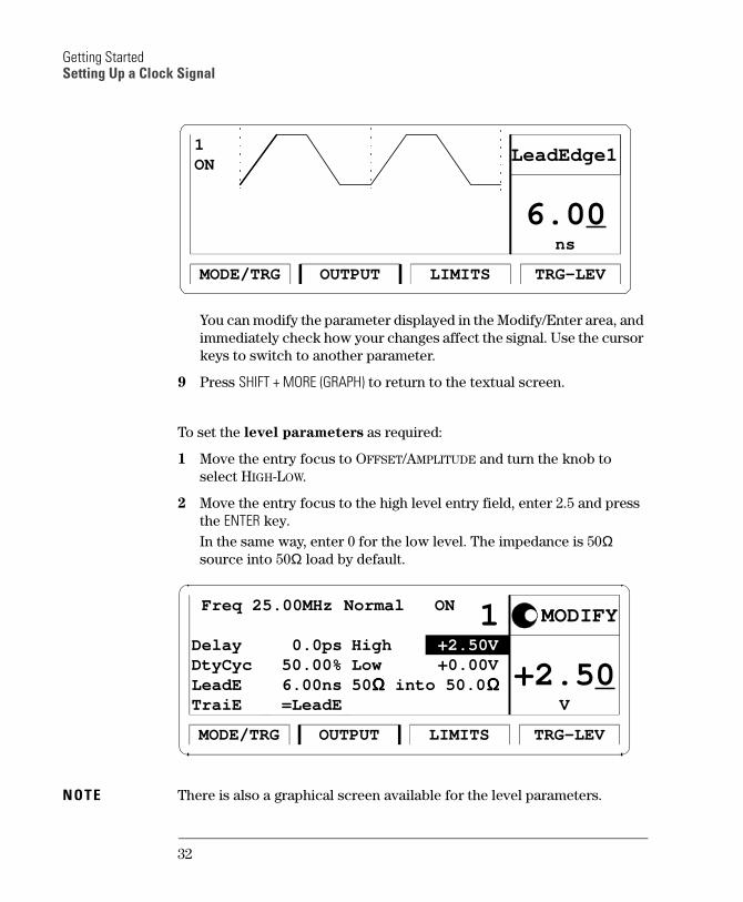
You can modify the parameter displayed in the Modify/Enter area, and immediately check how your changes affect the signal. Use the cursor keys to switch to another parameter.
9 Press SHIFT + MORE (GRAPH) to return to the textual screen.
To set the level parameters as required:
1 Move the entry focus to OFFSET/AMPLITUDE and turn the knob to select HIGH-LOW.
2 Move the entry focus to the high level entry field, enter 2.5 and press the ENTER key.In the same way, enter 0 for the low level. The impedance is 50Ω source into 50Ω load by default.
NOTE There is also a graphical screen available for the level parameters.
OUTPUT TRG-LEVLIMITSMODE/TRG
1ON
ns
6.00
LeadEdge1
V
+2.50
Freq 25.00MHz Normal ON
OUTPUT TRG-LEVLIMITSMODE/TRG
Delay
1 0.0ps
DtyCycLeadETraiE
50.00% 6.00ns =LeadE
HighLow
+2.50V +0.00V
50ΩΩΩΩ into 50.0 ΩΩΩΩ
MODIFY
32
Getting StartedSetting Up a Clock Signal
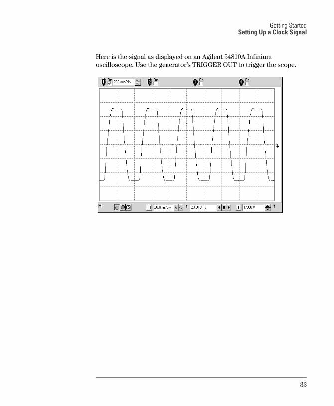
Here is the signal as displayed on an Agilent 54810A Infinium oscilloscope. Use the generator’s TRIGGER OUT to trigger the scope.
33
Getting StartedSetting Up a Clock Signal
Programming
Example
If you want to include this clock signal in your GP-IB program, use the following command lines. The comment lines starting with a # are not required.
# Reset the instrument to start from a defined, default status.*RST
# Switch off the automatic display update to increase programming# speed.:DISPlay OFF
# Internal PLL has to be set as period source.:ARM:SOURce INT2
# Set the frequency to 25 MHz, the duty cycle to 50 % and the# leading and trailing edge to 6 ns.:FREQuency 25 MHZ:PULSe:DCYCle 50:PULSe:TRANsition 6NS
# Set the high level to 2.5 Volts, the low level to 0.0 Volts.:VOLTage:HIGH 2.5V:VOLTage:LOW 0V
# Enable the output.:OUTPut ON
34
Getting StartedSetting Up a Pulse Signal
Setting Up a Pulse Signal
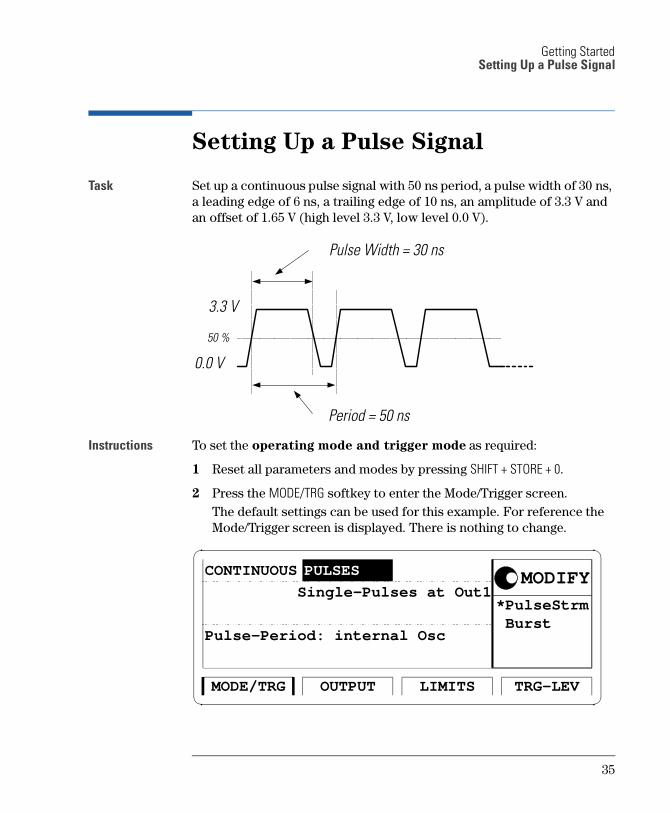
Task Set up a continuous pulse signal with 50 ns period, a pulse width of 30 ns, a leading edge of 6 ns, a trailing edge of 10 ns, an amplitude of 3.3 V and an offset of 1.65 V (high level 3.3 V, low level 0.0 V).
Instructions To set the operating mode and trigger mode as required:
1 Reset all parameters and modes by pressing SHIFT + STORE + 0.
2 Press the MODE/TRG softkey to enter the Mode/Trigger screen. The default settings can be used for this example. For reference the Mode/Trigger screen is displayed. There is nothing to change.
Pulse Width = 30 ns
Period = 50 ns
3.3 V
0.0 V
50 %
*PulseStrm Burst
OUTPUT TRG-LEVLIMITSMODE/TRG
CONTINUOUS
Single-Pulses at Out1
Pulse-Period: internal Osc
MODIFYPULSES
35
Getting StartedSetting Up a Pulse Signal
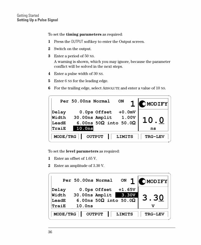
To set the timing parameters as required:
1 Press the OUTPUT softkey to enter the Output screen.
2 Switch on the output.
3 Enter a period of 50 NS. A warning is shown, which you may ignore, because the parameter conflict will be solved in the next steps.
4 Enter a pulse width of 30 NS.
5 Enter 6 NS for the leading edge.
6 For the trailing edge, select ABSOLUTE and enter a value of 10 NS.
To set the level parameters as required:
1 Enter an offset of 1.65 V.
2 Enter an amplitude of 3.30 V.
ns
10.0
Per 50.00ns Normal ON
OUTPUT TRG-LEVLIMITSMODE/TRG
Delay
1 0.0ps
WidthLeadETraiE
30.00ns 6.00ns 10.0ns
OffsetAmplit
+0.0mV 1.00V
50ΩΩΩΩ into 50.0 ΩΩΩΩ
MODIFY
V
3.30
Per 50.00ns Normal ON
OUTPUT TRG-LEVLIMITSMODE/TRG
Delay
1 0.0ps
WidthLeadETraiE
30.00ns 6.00ns 10.0ns
OffsetAmplit
+1.65V 3.30V
50ΩΩΩΩ into 50.0 ΩΩΩΩ
MODIFY
36
Getting StartedSetting Up a Pulse Signal
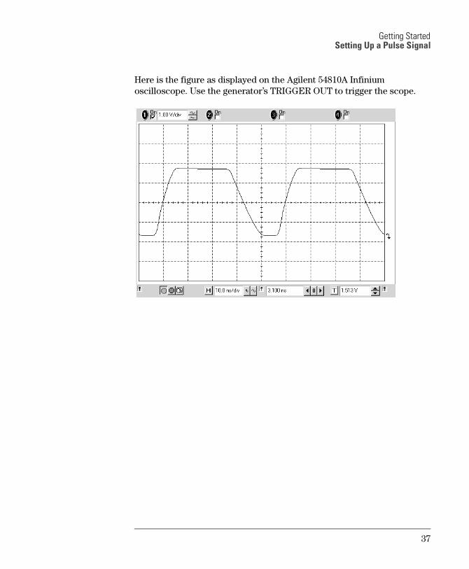
Here is the figure as displayed on the Agilent 54810A Infinium oscilloscope. Use the generator’s TRIGGER OUT to trigger the scope.
37
Getting StartedSetting Up a Pulse Signal
Programming
Example
If you want to include this pulse signal in your GP-IB program, use the following command lines. The comment lines starting with a # are not required.
# Reset the instrument to start from a defined, default status.*RST
# Switch off the automatic display update to increase programming# speed.:DISPlay OFF
# Pulse stream operating mode is required, but as we start # from a default status it is not necessary to send a command for # setting the instrument into pulse stream operating mode.# Set the period to 50 ns, the pulse width to 20 ns, the leading # edge to 6 ns and the trailing edge to 10 ns. :PULSe:PERiod 50NS:PULSe:WIDTh 30NS:PULSe:TRANsition 6NS:PULSe:TRANsition:TRAiling:AUTO OFF:PULSe:TRANsition:TRAiling 10NS
# Set the amplitude to 3.3 Volts, the offset to 1.65 Volts.:VOLTage 3.3V:VOLTage:OFFSet 1.65V
# Enable the output:OUTPut ON
38
Getting StartedSetting Up a Burst Signal
Setting Up a Burst Signal
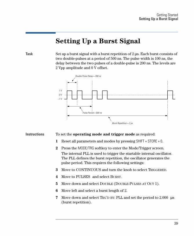
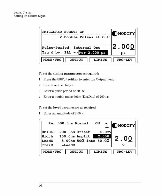
Task Set up a burst signal with a burst repetition of 2 µs. Each burst consists of two double-pulses at a period of 500 ns. The pulse width is 100 ns, the delay between the two pulses of a double-pulse is 200 ns. The levels are 2 Vpp amplitude and 0 V offset.
Instructions To set the operating mode and trigger mode as required:
1 Reset all parameters and modes by pressing SHIFT + STORE + 0.
2 Press the MODE/TRG softkey to enter the Mode/Trigger screen. The internal PLL is used to trigger the startable internal oscillator. The PLL defines the burst repetition, the oscillator generates the pulse period. This requires the following settings:
3 Move to CONTINUOUS and turn the knob to select TRIGGERED.
4 Move to PULSES and select BURST.
5 Move down and select DOUBLE (DOUBLE-PULSES AT OUT 1).
6 Move left and select a burst length of 2.
7 Move down and select TRG’D BY: PLL and set the period to 2.000 µs (burst repetition).
Double Pulse Delay = 200 ns
Burst Repetition = 2 µs
Pulse Period = 500 ns
1 V
0 V
1 V
39
Getting StartedSetting Up a Burst Signal
To set the timing parameters as required:
1 Press the OUTPUT softkey to enter the Output menu.
2 Switch on the Output.
3 Enter a pulse period of 500 NS.
4 Enter a double-pulse delay (DBLDEL) of 200 NS.
To set the level parameters as required:
1 Enter an amplitude of 2.00 V.
µµµµs
2.000
OUTPUT TRG-LEVLIMITSMODE/TRG
2-Double-Pulses at Out1
TRIGGERED BURSTS OF
Trg'd by: PLL ->
MODIFY
Per 2.000 µµµµs
Pulse-Period: internal Osc
V
2.00
Per 500.0ns Normal ON
OUTPUT TRG-LEVLIMITSMODE/TRG
DblDel
1 200.0ns
WidthLeadETraiE
100.0ns 5.00ns =LeadE
OffsetAmplit
+0.0mV 2.00V
50ΩΩΩΩ into 50.0 ΩΩΩΩ
MODIFY
40
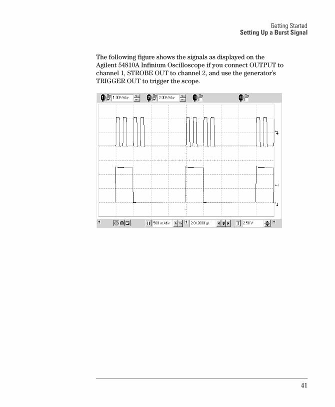
Getting StartedSetting Up a Burst Signal
The following figure shows the signals as displayed on the Agilent 54810A Infinium Oscilloscope if you connect OUTPUT to channel 1, STROBE OUT to channel 2, and use the generator’s TRIGGER OUT to trigger the scope.
41
Getting StartedSetting Up a Burst Signal
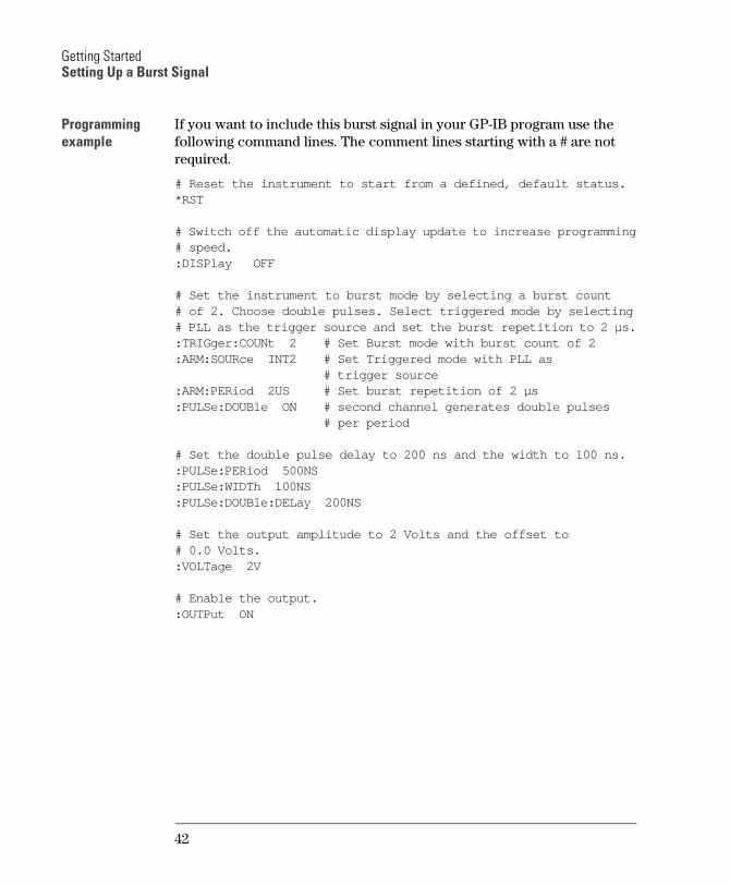
Programming
example
If you want to include this burst signal in your GP-IB program use the following command lines. The comment lines starting with a # are not required.
# Reset the instrument to start from a defined, default status.*RST
# Switch off the automatic display update to increase programming# speed.:DISPlay OFF
# Set the instrument to burst mode by selecting a burst count # of 2. Choose double pulses. Select triggered mode by selecting# PLL as the trigger source and set the burst repetition to 2 µs.:TRIGger:COUNt 2 # Set Burst mode with burst count of 2:ARM:SOURce INT2 # Set Triggered mode with PLL as
# trigger source:ARM:PERiod 2US # Set burst repetition of 2 µs:PULSe:DOUBle ON # second channel generates double pulses
# per period
# Set the double pulse delay to 200 ns and the width to 100 ns.:PULSe:PERiod 500NS:PULSe:WIDTh 100NS:PULSe:DOUBle:DELay 200NS
# Set the output amplitude to 2 Volts and the offset to # 0.0 Volts. :VOLTage 2V
# Enable the output.:OUTPut ON
42
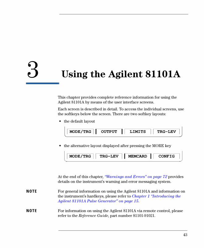
3 3Using the Agilent 81101A
This chapter provides complete reference information for using the
Agilent 81101A by means of the user interface screens.
Each screen is described in detail. To access the individual screens, use
the softkeys below the screen. There are two softkey layouts:
the default layout
the alternative layout displayed after pressing the MORE key
At the end of this chapter, Warnings and Errors on page 72 provides
details on the instruments warning and error messaging system.
NOTE For general information on using the Agilent 81101A and information on
the instruments hardkeys, please refer to Chapter 1 Introducing the
Agilent 81101A Pulse Generator on page 15.
NOTE For information on using the Agilent 81101A via remote control, please
refer to the Reference Guide, part number 81101-91021.
OUTPUT TRG-LEVLIMITSMODE/TRG
TRG-LEV CONFIGMEMCARDMODE/TRG
43
Using the Agilent 81101AThe Mode/Trigger Screen
The Mode/Trigger Screen
This section describes the Mode/Trigger screen, starting with an
overview of the available parameter combinations, followed by detailed
descriptions of each combination.
Overview
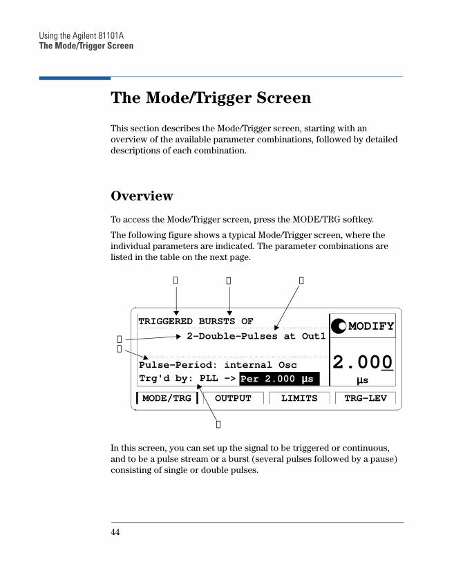
To access the Mode/Trigger screen, press the MODE/TRG softkey.
The following figure shows a typical Mode/Trigger screen, where the
individual parameters are indicated. The parameter combinations are
listed in the table on the next page.
In this screen, you can set up the signal to be triggered or continuous,
and to be a pulse stream or a burst (several pulses followed by a pause)
consisting of single or double pulses.
µµµµs
2.000
OUTPUT TRG-LEVLIMITSMODE/TRG
2-Double-Pulses at Out1
TRIGGERED BURSTS OF
Trg'd by: PLL ->
MODIFY
Per 2.000 µµµµs
Pulse-Period: internal Osc
➀ ➁ ➂
➃➄
➅
44
Using the Agilent 81101AThe Mode/Trigger Screen
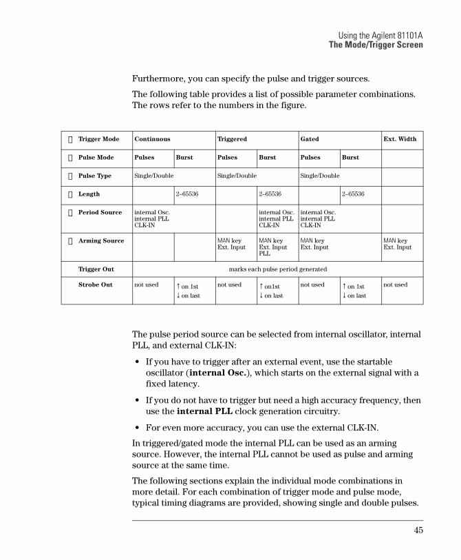
Furthermore, you can specify the pulse and trigger sources.
The following table provides a list of possible parameter combinations.
The rows refer to the numbers in the figure.
The pulse period source can be selected from internal oscillator, internal
PLL, and external CLK-IN:
If you have to trigger after an external event, use the startable
oscillator (internal Osc.), which starts on the external signal with a
fixed latency.
If you do not have to trigger but need a high accuracy frequency, then
use the internal PLL clock generation circuitry.
For even more accuracy, you can use the external CLK-IN.
In triggered/gated mode the internal PLL can be used as an arming
source. However, the internal PLL cannot be used as pulse and arming
source at the same time.
The following sections explain the individual mode combinations in
more detail. For each combination of trigger mode and pulse mode,
typical timing diagrams are provided, showing single and double pulses.
➀ Trigger Mode Continuous Triggered Gated Ext. Width
➁ Pulse Mode Pulses Burst Pulses Burst Pulses Burst
➂ Pulse Type Single/Double Single/Double Single/Double
➃ Length 265536 265536 265536
➄ Period Source internal Osc.internal PLLCLK-IN
internal Osc.internal PLLCLK-IN
internal Osc.internal PLLCLK-IN
➅ Arming Source MAN keyExt. Input
MAN keyExt. InputPLL
MAN keyExt. Input
MAN keyExt. Input
Trigger Out marks each pulse period generated
Strobe Out not used ↑on 1st
↓on last
not used ↑on1st
↓on last
not used ↑on 1st
↓on last
not used
45
Using the Agilent 81101AThe Mode/Trigger Screen
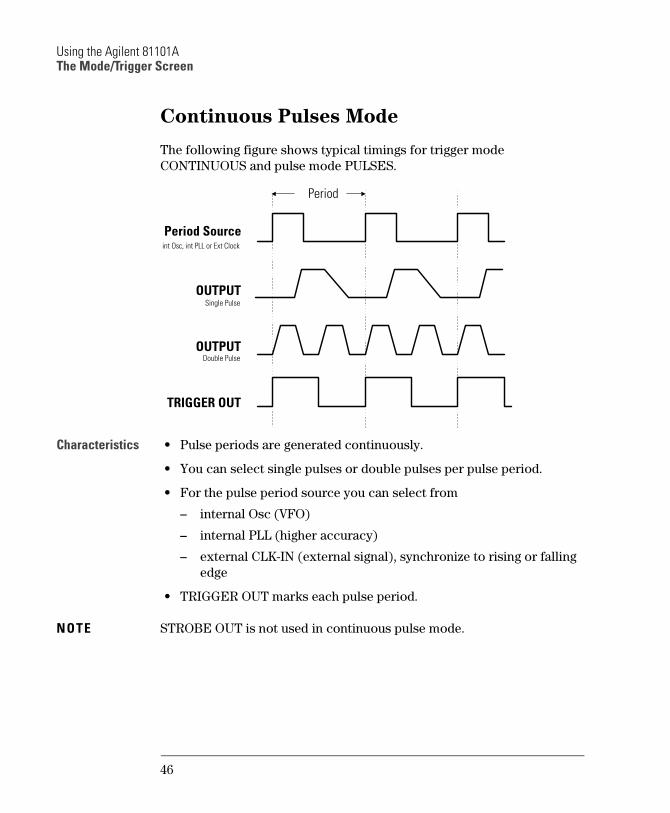
Continuous Pulses Mode
The following figure shows typical timings for trigger mode
CONTINUOUS and pulse mode PULSES.
Characteristics Pulse periods are generated continuously.
You can select single pulses or double pulses per pulse period.
For the pulse period source you can select from
internal Osc (VFO)
internal PLL (higher accuracy)
external CLK-IN (external signal), synchronize to rising or falling
edge
TRIGGER OUT marks each pulse period.
NOTE STROBE OUT is not used in continuous pulse mode.
Period
OUTPUT
OUTPUT
TRIGGER OUT
Period Source
int Osc, int PLL or Ext Clock
Single Pulse
Double Pulse
46
Using the Agilent 81101AThe Mode/Trigger Screen
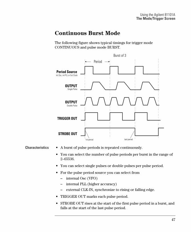
Continuous Burst Mode
The following figure shows typical timings for trigger mode
CONTINUOUS and pulse mode BURST.
Characteristics A burst of pulse periods is repeated continuously.
You can select the number of pulse periods per burst in the range of
265536.
You can select single pulses or double pulses per pulse period.
For the pulse period source you can select from
internal Osc (VFO)
internal PLL (higher accuracy)
external CLK-IN, synchronize to rising or falling edge.
TRIGGER OUT marks each pulse period.
STROBE OUT rises at the start of the first pulse period in a burst, and
falls at the start of the last pulse period.
Period
OUTPUT
OUTPUT
TRIGGER OUT
Period Source int Osc, int PLL or Ext Clock
Single Pulse
Double Pulse
STROBE OUT
Burst of 3
1st period last period
47
Using the Agilent 81101AThe Mode/Trigger Screen
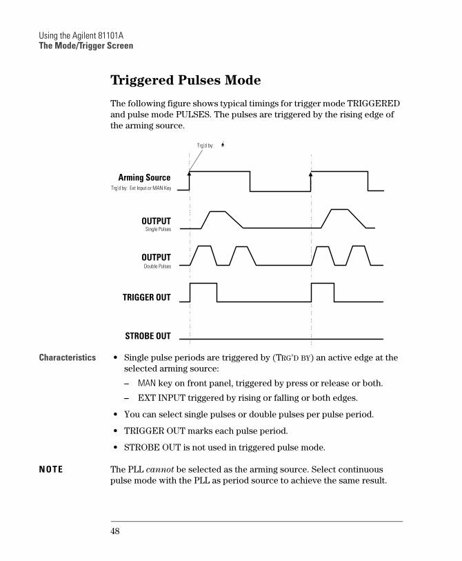
Triggered Pulses Mode
The following figure shows typical timings for trigger mode TRIGGERED
and pulse mode PULSES. The pulses are triggered by the rising edge of
the arming source.
Characteristics Single pulse periods are triggered by (TRG'D BY) an active edge at the
selected arming source:
MAN key on front panel, triggered by press or release or both.
EXT INPUT triggered by rising or falling or both edges.
You can select single pulses or double pulses per pulse period.
TRIGGER OUT marks each pulse period.
STROBE OUT is not used in triggered pulse mode.
NOTE The PLL cannot be selected as the arming source. Select continuous
pulse mode with the PLL as period source to achieve the same result.
OUTPUT
OUTPUT
TRIGGER OUT
Arming SourceTrg'd by: Ext Input or MAN Key
Single Pulses
Double Pulses
STROBE OUT
Trg'd by:
48
Using the Agilent 81101AThe Mode/Trigger Screen
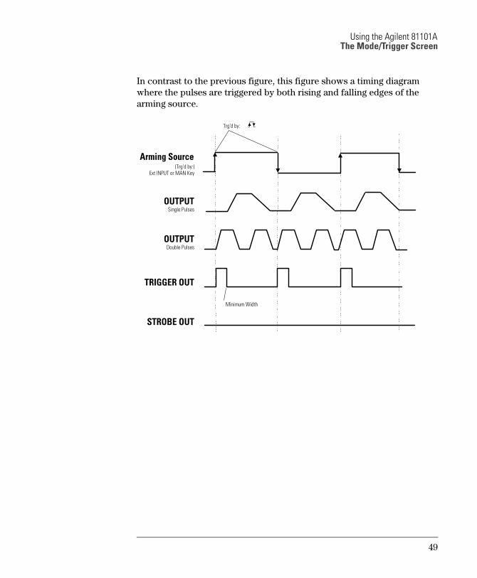
In contrast to the previous figure, this figure shows a timing diagram
where the pulses are triggered by both rising and falling edges of the
arming source.
OUTPUT
OUTPUT
TRIGGER OUT
Arming Source (Trg'd by:)
Ext INPUT or MAN Key
Single Pulses
Double Pulses
STROBE OUT
Trg'd by:
Minimum Width
49
Using the Agilent 81101AThe Mode/Trigger Screen
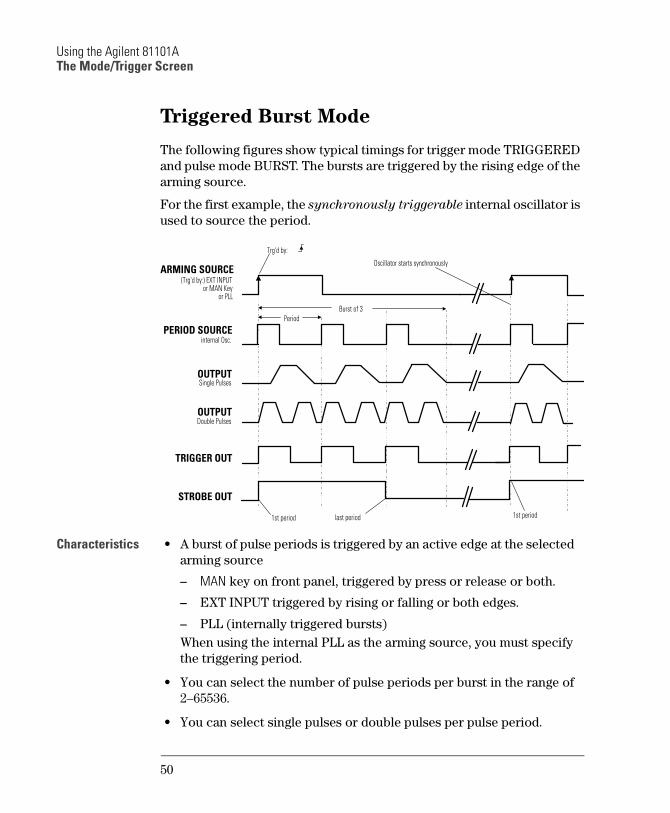
Triggered Burst Mode
The following figures show typical timings for trigger mode TRIGGERED
and pulse mode BURST. The bursts are triggered by the rising edge of the
arming source.
For the first example, the synchronously triggerable internal oscillator is
used to source the period.
Characteristics A burst of pulse periods is triggered by an active edge at the selected
arming source
MAN key on front panel, triggered by press or release or both.
EXT INPUT triggered by rising or falling or both edges.
PLL (internally triggered bursts)
When using the internal PLL as the arming source, you must specify
the triggering period.
You can select the number of pulse periods per burst in the range of
265536.
You can select single pulses or double pulses per pulse period.
PERIOD SOURCE
OUTPUT
OUTPUT
TRIGGER OUT
internal Osc.
Double Pulses
STROBE OUT
Single Pulses
1st period last period 1st period
Burst of 3
Period
ARMING SOURCEOscillator starts synchronously
(Trg'd by:) EXT INPUTor MAN Key
or PLL
Trg'd by:
50
Using the Agilent 81101AThe Mode/Trigger Screen
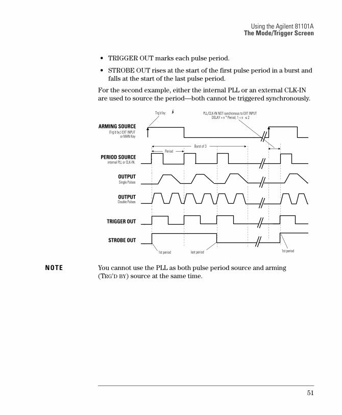
TRIGGER OUT marks each pulse period.
STROBE OUT rises at the start of the first pulse period in a burst and
falls at the start of the last pulse period.
For the second example, either the internal PLL or an external CLK-IN
are used to source the periodboth cannot be triggered synchronously.
NOTE You cannot use the PLL as both pulse period source and arming
(TRG'D BY) source at the same time.
PERIOD SOURCE
OUTPUT
OUTPUT
TRIGGER OUT
internal PLL or CLK-IN.
Double Pulses
STROBE OUT
Single Pulses
ARMING SOURCE
1st period last period 1st period
Trg'd by:
(Trg'd by:) EXT INPUTor MAN Key
PLL/CLK-IN NOT synchronous to EXT INPUTDELAY = n * Period, 1 < n ≤ 2
Period
Burst of 3
51
Using the Agilent 81101AThe Mode/Trigger Screen
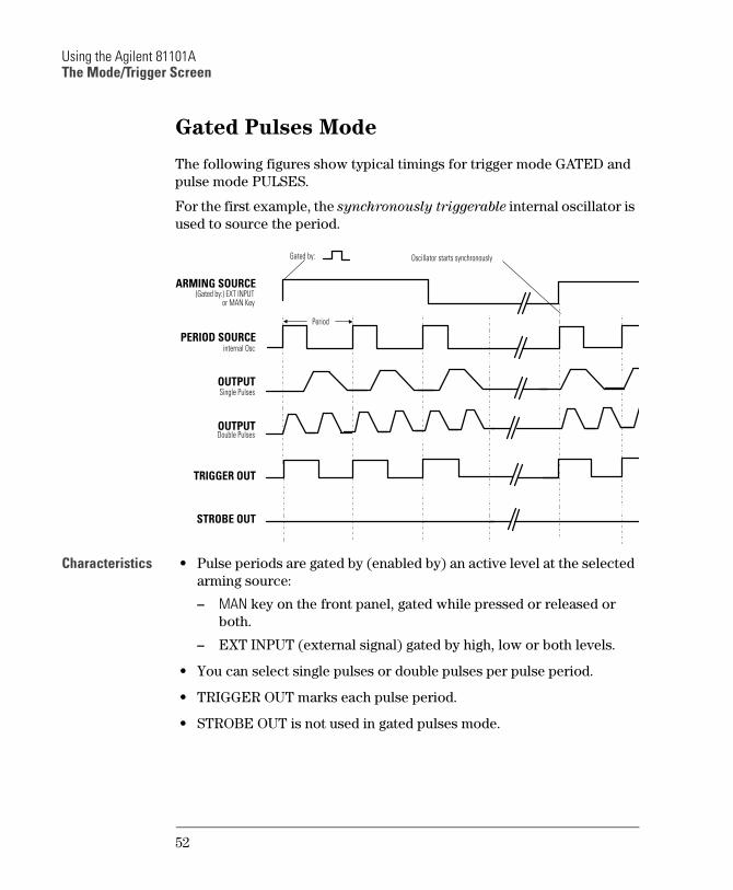
Gated Pulses Mode
The following figures show typical timings for trigger mode GATED and
pulse mode PULSES.
For the first example, the synchronously triggerable internal oscillator is
used to source the period.
Characteristics Pulse periods are gated by (enabled by) an active level at the selected
arming source:
MAN key on the front panel, gated while pressed or released or
both.
EXT INPUT (external signal) gated by high, low or both levels.
You can select single pulses or double pulses per pulse period.
TRIGGER OUT marks each pulse period.
STROBE OUT is not used in gated pulses mode.
PERIOD SOURCE
ARMING SOURCE
OUTPUT
OUTPUT
TRIGGER OUT
internal Osc
Double Pulses
STROBE OUT
Single Pulses
Gated by:
(Gated by:) EXT INPUTor MAN Key
Oscillator starts synchronously
Period
52
Using the Agilent 81101AThe Mode/Trigger Screen
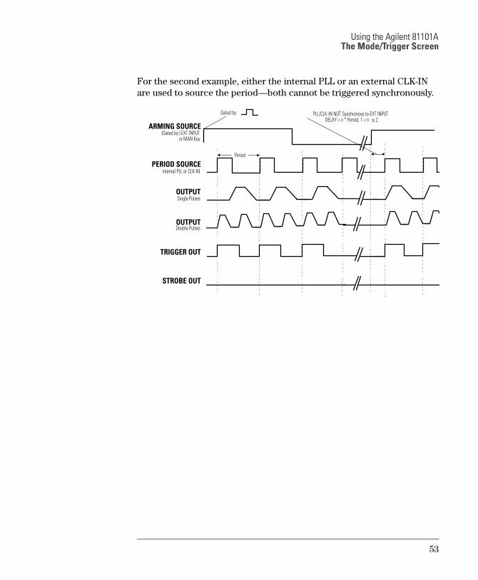
For the second example, either the internal PLL or an external CLK-IN
are used to source the periodboth cannot be triggered synchronously.
PERIOD SOURCE
ARMING SOURCE
OUTPUT
OUTPUT
TRIGGER OUT
internal PLL or CLK-IN
Double Pulses
STROBE OUT
Single Pulses
Gated by:
(Gated by:) EXT INPUTor MAN Key
Period
PLL/CLK-IN NOT Synchronous to EXT INPUTDELAY = n * Period, 1 < n ≤ 2
53
Using the Agilent 81101AThe Mode/Trigger Screen
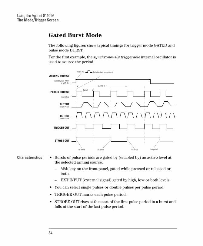
Gated Burst Mode
The following figures show typical timings for trigger mode GATED and
pulse mode BURST.
For the first example, the synchronously triggerable internal oscillator is
used to source the period.
Characteristics Bursts of pulse periods are gated by (enabled by) an active level at
the selected arming source:
MAN key on the front panel, gated while pressed or released or
both.
EXT INPUT (external signal) gated by high, low or both levels.
You can select single pulses or double pulses per pulse period.
TRIGGER OUT marks each pulse period.
STROBE OUT rises at the start of the first pulse period in a burst and
falls at the start of the last pulse period.
PERIOD SOURCE
ARMING SOURCE
OUTPUT
OUTPUT
TRIGGER OUT
internal Osc.
Double Pulses
STROBE OUT
Single Pulses
Gated by:
(Gated by:) EXT INPUTor MAN Key
Period
Oscillator starts synchronously
1st period last period 1st period last period
Burst of 3
54
Using the Agilent 81101AThe Mode/Trigger Screen
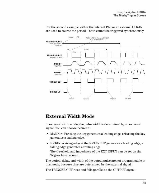
For the second example, either the internal PLL or an external CLK-IN
are used to source the periodboth cannot be triggered synchronously.
External Width Mode
In external width mode, the pulse width is determined by an external
signal. You can choose between:
MANKEY: Pressing the key generates a leading edge, releasing the key
generates a trailing edge.
EXT-IN: A rising edge at the EXT INPUT generates a leading edge, a
falling edge generates a trailing edge.
The threshold and impedance of the EXT INPUT can be set on the
Trigger Level screen.
The period, delay, and width of the output pulse are not programmable in
this mode, because they are determined by the external signal.
The TRIGGER OUT rises and falls parallel to the OUTPUT signal.
PERIOD SOURCE
ARMING SOURCE
OUTPUT
OUTPUT
TRIGGER OUT
internal PLL. or CLK-IN
Double Pulses
STROBE OUT
Single Pulses
Gated by:
(Gated by:) EXT INPUTor MAN Key
Period
1st period last period 1st period last period
Burst of 3
PLL/CLK-IN NOT Synchronous to EXT INPUTDELAY = n * Period, 1 < n ≤ 2
55
Using the Agilent 81101AThe Output Screen
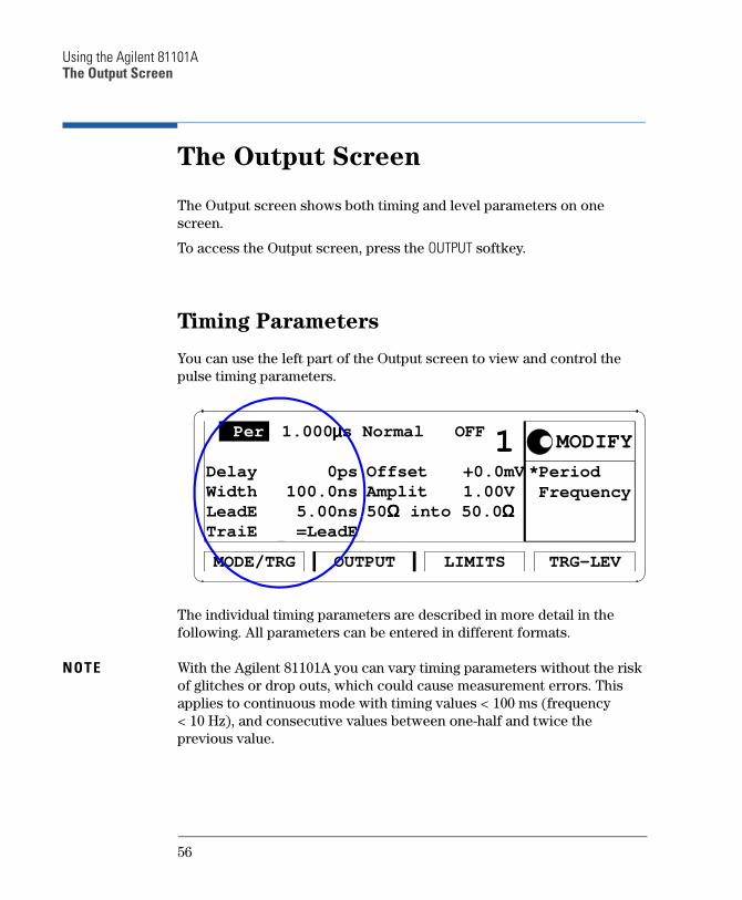
The Output Screen
The Output screen shows both timing and level parameters on one
screen.
To access the Output screen, press the OUTPUT softkey.
Timing Parameters
You can use the left part of the Output screen to view and control the
pulse timing parameters.
The individual timing parameters are described in more detail in the
following. All parameters can be entered in different formats.
NOTE With the Agilent 81101A you can vary timing parameters without the risk
of glitches or drop outs, which could cause measurement errors. This
applies to continuous mode with timing values < 100 ms (frequency
< 10 Hz), and consecutive values between one-half and twice the
previous value.
*Period Frequency
1.000 µµµµs Normal OFF
OUTPUT TRG-LEVLIMITSMODE/TRG
Delay
1 0ps
WidthLeadETraiE
100.0ns 5.00ns =LeadE
OffsetAmplit
+0.0mV 1.00V
50ΩΩΩΩ into 50.0 ΩΩΩΩ
MODIFY Per
56
Using the Agilent 81101AThe Output Screen
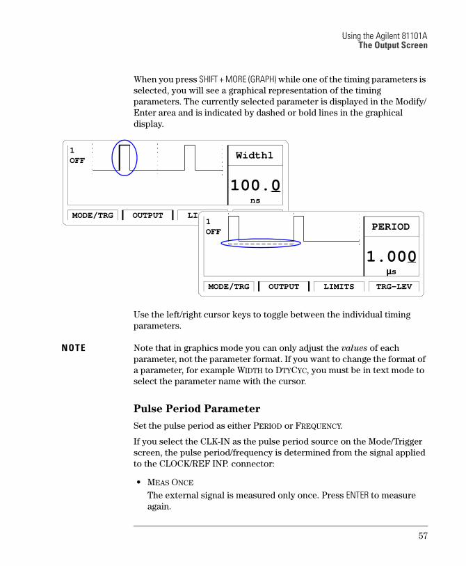
When you press SHIFT + MORE (GRAPH) while one of the timing parameters is
selected, you will see a graphical representation of the timing
parameters. The currently selected parameter is displayed in the Modify/
Enter area and is indicated by dashed or bold lines in the graphical
display.
Use the left/right cursor keys to toggle between the individual timing
parameters.
NOTE Note that in graphics mode you can only adjust the values of each
parameter, not the parameter format. If you want to change the format of
a parameter, for example WIDTH to DTYCYC, you must be in text mode to
select the parameter name with the cursor.
Pulse Period Parameter
Set the pulse period as either PERIOD or FREQUENCY.
If you select the CLK-IN as the pulse period source on the Mode/Trigger
screen, the pulse period/frequency is determined from the signal applied
to the CLOCK/REF INP. connector:
MEAS ONCE
The external signal is measured only once. Press ENTER to measure
again.
ns
100.0
OUTPUT TRG-LEVLIMITSMODE/TRG
1OFF
Width1
µµµµs
1.000
OUTPUT TRG-LEVLIMITSMODE/TRG
1OFF
PERIOD
57
Using the Agilent 81101AThe Output Screen
MEAS CONT
The external signal is continuously measured until the instrument
receives a command via GP-IB.
To invoke continuous measurements again, you have to bring the
instrument in local operating mode by pressing SHIFT (LOCAL) and start
continuous measurement again.
Pulse Delay Parameter
Delay the leading edge of the pulse within the pulse period. There are
three delay formats available:
DELAY or DBLDEL (select ABSOLUTE)
DELAY is the absolute delay from the start of a pulse period to the
start of the leading edge of the pulse.
If double pulses are selected on the Mode/Trigger screen, the DBLDEL
parameter specifies the delay between the first and second pulse in
each pulse period.
The absolute delay is independent of the pulse period. So the leading
edge does not move relative to the start of the period if you change
the period.
DELAY% (select % OF PERIOD)
The delay from the start of the pulse period to the start of the leading
edge expressed as a percentage of the pulse period. In this format, if
you change the period, the leading edge moves relative to the start of
the period in order to maintain the percentage delay.
PHASE (select PHASE)
The phase delay in degrees from the start of the pulse period to the
start of the leading edge (360° = 1 pulse period). In this format, if you
change the period, the leading edge moves relative to the start of the
period in order to maintain the phase delay.
58

Using the Agilent 81101AThe Output Screen
Pulse Width Parameter
Set the width of the output pulse. There are three width formats
available:
WIDTH (select WIDTH)
The absolute pulse width measured from the start of the leading edge
to the start of the trailing edge. In this format, the pulse width is
independent of changes in pulse period and delay.
DTYCYC (select DUTYCYCLE)
The duty cycle is the pulse width measured from the start of the
leading edge to the start of the trailing edge expressed as a
percentage of the period. In this format, if you adjust the period, the
absolute width is adjusted to maintain the duty cycle.
TRADEL (select TRAILDEL)
The trailing delay is the absolute delay from the start of the pulse-
period to the start of the trailing edge. In this format the trailing edge
remains fixed relative to the start of the pulse period if you adjust the
pulse delay (leading edge delay) or the pulse period.
NOTE You cannot have the width format set to DTYCYC and the leading/trailing-
edge format set to percentage of width (LEADED%/TRAILE%) at the same
time.
Leading Edge Parameter
Set the leading edge transition time of the pulse, measured from 10% to
90% of the pulse amplitude. There are two formats available:
LEADE (select ABSOLUTE)
The absolute transition time measured from 10% to 90% of the pulse
amplitude. In this format the leading edge is independent of the pulse
width.
LEADE% (select % OF WID)
The absolute transition time expressed as a percentage of the pulse
width. In this format, if you adjust the pulse width, the transition time
is adjusted to maintain the edge time as a percentage of the width.
59
Using the Agilent 81101AThe Output Screen
NOTE The leading and trailing edges are independently programmable within
certain ranges only, see Transition Times in the Reference Guide.
NOTE You cannot have the width format set to DTYCYC and the leading/trailing-
edge format set to percentage of width (LEADE%/TRAIE%) at the same
time.
Pulse Trailing Edge Parameter
Set the trailing edge transition-time of the pulse, measured from 10% to
90% of the pulse amplitude. There are three formats available:
=LEADE (select =LEADE)
The trailing edge transition time is coupled directly to the leading
edge to maintain a symmetrical pulse.
TRAIE (select ABSOLUTE)
The absolute transition time measured from 90% to 10% of the pulse
amplitude. In this format the trailing edge is independent of the
leading edge and the pulse width.
TRAIE% (select % OF WID)
The trailing edge transition time expressed as a percentage of the
pulse width. In this format, if you adjust the pulse width, the
transition time is adjusted to maintain the edge time as a percentage
of the width.
NOTE The leading and trailing edges are independently programmable within
certain ranges only, see Transition Times in the Reference Guide.
NOTE You cannot have the width format set to DTYCYC and the leading/trailing
edge format set to percentage of width (LEADE%/TRAIE%) at the same
time.
60
Using the Agilent 81101AThe Output Screen
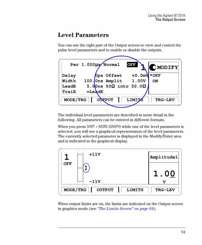
Level Parameters
You can use the right part of the Output screen to view and control the
pulse level parameters and to enable or disable the outputs.
The individual level parameters are described in more detail in the
following. All parameters can be entered in different formats.
When you press SHIFT + MORE (GRAPH) while one of the level parameters is
selected, you will see a graphical representation of the level parameters.
The currently selected parameter is displayed in the Modify/Enter area
and is indicated in the graphical display.
When output limits are on, the limits are indicated on the Output screen in graphics mode (see The Limits Screen on page 64).
Per 1.000 µµµµs Normal
OUTPUT TRG-LEVLIMITSMODE/TRG
OFF
Delay
1 0ps
WidthLeadETraiE
100.0ns 5.00ns =LeadE
OffsetAmplit
+0.0mV 1.00V
50ΩΩΩΩ into 50.0 ΩΩΩΩ
*OFF ON
MODIFY
1.00V
OUTPUT TRG-LEVLIMITSMODE/TRG
1 +11V
-11V
Amplitude1
OFF
61
Using the Agilent 81101AThe Output Screen
NOTE Note that in graphics mode you can only adjust the values of each
parameter, not the parameter format. If you want to change the format of
a parameter, for example OFFS-AMPL to HIGH-LOW, you must be in text
mode to select the parameter name with the cursor.
NOTE When the output is switched on, the instrument monitors the actual
voltage and current levels at the output. The output is automatically
switched off if voltage levels or power dissipation reach levels which
could damage the output circuits.
Normal/Complement Parameter
Switch the output between normal and complement mode:
NORMAL
Pulse leading edge rises from low to high level, trailing edge falls from
high to low level.
COMPLMNT
Pulse leading edge falls from high to low level, trailing edge rises from
low to high level.
NOTE This parameter is only available in text mode.
Offset/Amplitude, High/Low Level Parameters
Set and display the pulse levels in terms of either offset and amplitude, or
high and low level. You can quickly set TTL or ECL output levels using
the SET TTL and SET ECL formats.
SET TTL
Select high and low level formats and automatically set the levels to
the default TTL levels:
TTL-HI: +2.50 V
TTL-LOW: +0.0 mV
The default levels are set once and can be adjusted afterwards by
moving the entry focus to the values as normal.
HIGH-LOW
Select high and low level format for the pulse levels.
62
Using the Agilent 81101AThe Output Screen
OFFS-AMPL
Select offset and amplitude format for the pulse levels. Offset is
measured from 0V to the middle of the pulse amplitude. Pulse
amplitude is the difference between the high and low levels of the
pulse.
SET ECL
Select high and low level format and automatically set the levels to
the default ECL levels:
ECL-HI: 850 mV
ECL-LOW: 1.80 V
These default levels are set once and can be adjusted afterwards by
moving the entry focus to the value as normal.
Voltage/Current Mode (mV/V/mA/A)
Move the entry focus onto the level units to select between setting the
pulse levels IN VOLTS or IN AMPERES.
NOTE This parameter is only available in text mode.
Output Source Impedance Parameter (50Ω into)
Select an output source impedance of 50 Ω or 1 kΩ.
NOTE This parameter is only available in text mode
Load Impedance Parameter (50.0Ω)
Adjust the load impedance value expected at the output to compensate
for non-50Ω loads. The displayed level parameters are then calculated
using this value and therefore represent the levels at a non-50Ω static
load.
NOTE This parameter is only available in text mode.
63
Using the Agilent 81101AThe Limits Screen
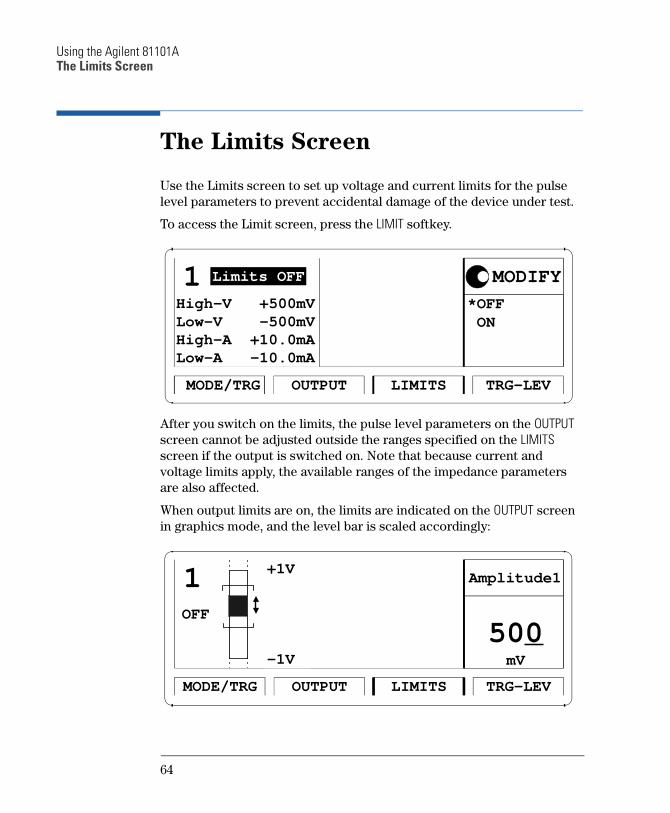
The Limits Screen
Use the Limits screen to set up voltage and current limits for the pulse
level parameters to prevent accidental damage of the device under test.
To access the Limit screen, press the LIMIT softkey.
After you switch on the limits, the pulse level parameters on the OUTPUT
screen cannot be adjusted outside the ranges specified on the LIMITS
screen if the output is switched on. Note that because current and
voltage limits apply, the available ranges of the impedance parameters
are also affected.
When output limits are on, the limits are indicated on the OUTPUT screen in graphics mode, and the level bar is scaled accordingly:
*OFF ON
OUTPUT TRG-LEVLIMITSMODE/TRG
1 Limits OFF
Low-A -10.0mAHigh-A +10.0mALow-V -500mVHigh-V +500mV
MODIFY
500mV
OUTPUT TRG-LEVLIMITSMODE/TRG
1 +1V
-1V
Amplitude1
OFF
64
Using the Agilent 81101AThe Trigger-Level Screen
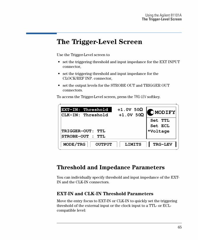
The Trigger-Level Screen
Use the Trigger-Level screen to
set the triggering threshold and input impedance for the EXT INPUT
connector,
set the triggering threshold and input impedance for the
CLOCK/REF INP. connector,
set the output levels for the STROBE OUT and TRIGGER OUT
connectors.
To access the Trigger-Level screen, press the TRG-LEV softkey.
Threshold and Impedance Parameters
You can individually specify threshold and input impedance of the EXT-
IN and the CLK-IN connectors.
EXT-IN and CLK-IN Threshold Parameters
Move the entry focus to EXT-IN or CLK-IN to quickly set the triggering
threshold of the external input or the clock input to a TTL- or ECL-
compatible level:
Set TTL Set ECL*Voltage
+1.0V 50 ΩΩΩΩ
OUTPUT TRG-LEVLIMITSMODE/TRG
EXT-IN: Threshold
STROBE-OUT : TTLTRIGGER-OUT: TTL
CLK-IN: Threshold +1.0V 50 ΩΩΩΩ MODIFY
65
Using the Agilent 81101AThe Trigger-Level Screen
SET TTL
Set the input threshold to +2.5 V.
You can adjust the threshold by moving the entry focus to the value.
SET ECL
Set the input threshold to 1.3 V.
You can adjust the threshold by moving the entry focus to the value.
VOLTAGE
Set any threshold level in the range of 10.0 V to +10.0 V. Move the
entry focus to the value to adjust it.
EXT-IN and CLK-IN Impedance Parameters
Toggle the input impedance of the external input connector or the clock
input connector between 50 Ω and 10 kΩ.
Trigger and Strobe Level Parameters
You can individually set the output levels of the TRIGGER OUT
connector and the STROBE OUT connector.
Set the output levels (into 50 Ω) to
TTL
High level: +2.50 V
Low level: 0 V
ECL
High level: 0.85 V
Low level: 1.80 V
66
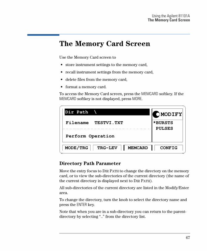
Using the Agilent 81101AThe Memory Card Screen
The Memory Card Screen
Use the Memory Card screen to
store instrument settings to the memory card,
recall instrument settings from the memory card,
delete files from the memory card,
format a memory card.
To access the Memory Card screen, press the MEMCARD softkey. If the
MEMCARD softkey is not displayed, press MORE.
Directory Path Parameter
Move the entry focus to DIR PATH to change the directory on the memory
card, or to view the sub-directories of the current directory (the name of
the current directory is displayed next to DIR PATH).
All sub-directories of the current directory are listed in the Modify/Enter
area.
To change the directory, turn the knob to select the directory name and
press the ENTER key.
Note that when you are in a sub-directory you can return to the parent-
directory by selecting .. from the directory list.
*BURSTS PULSES
TRG-LEV CONFIGMEMCARDMODE/TRG
Filename TESTVI.TXT
Perform Operation
MODIFYDir Path \
67
Using the Agilent 81101AThe Memory Card Screen
Filename Parameter
Move the entry focus to the FILENAME parameter to select a file from the
current directory. Use the knob to scroll through the filenames listed in
the Modify/Enter area.
Memory Card Operations
Move the entry focus to PERFORM OPERATION and use the knob to select
the required operation. Press the ENTER key to perform the operation.
READCARD
Read the DOS file system information from the memory card after
inserting a new card.
RECALL
Recall the selected file as the current instrument setting.
STORE
Store the current instrument setting to the memory card.
Press ENTER once to start editing the filename for the setting in the
Modify/Enter area. The currently selected filename is used as default.
CA UTIO N If you do not modify the filename, the existing file will be overwritten
when you press ENTER.
To modify the filename, move the character cursor with the cursor
keys. Modify a character using the knob. When you have finished,
press ENTER to store the setting.
The filename can be up to 8 characters long.
Press the cursor up or cursor down keys to cancel the store operation
at any time.
Note that the DOS filename suffix .ST0 is added automatically to the
filename when you store the current settings.
STORE ALL
Store the current instrument setting and the instrument setting
memories 1 to 9 to the memory card. Each setting is stored in a
separate file with the same name but different suffixes (.ST0 for the
current setting, ST1 to ST9 for setting memories 1 to 9).
68
Using the Agilent 81101AThe Memory Card Screen
Press ENTER once to start editing the filename for the setting in the
Modify/Enter area. The currently selected filename is used as default.
CA UTIO N If you do not modify the filename, the existing file will be overwritten
when you press ENTER.
To modify the filename, move the character cursor with the cursor
keys. Modify a character using the knob. When you have finished,
press ENTER to store the setting.
The filename can be up to 8 characters long.
Press the cursor up or cursor down keys to cancel the store operation
at any time.
DELETE
Delete the selected file from the memory card.
FORMAT
Format the memory card.
CA UTIO N Formatting a memory card destroys any existing files on the card.
69
Using the Agilent 81101AThe Configuration Screen
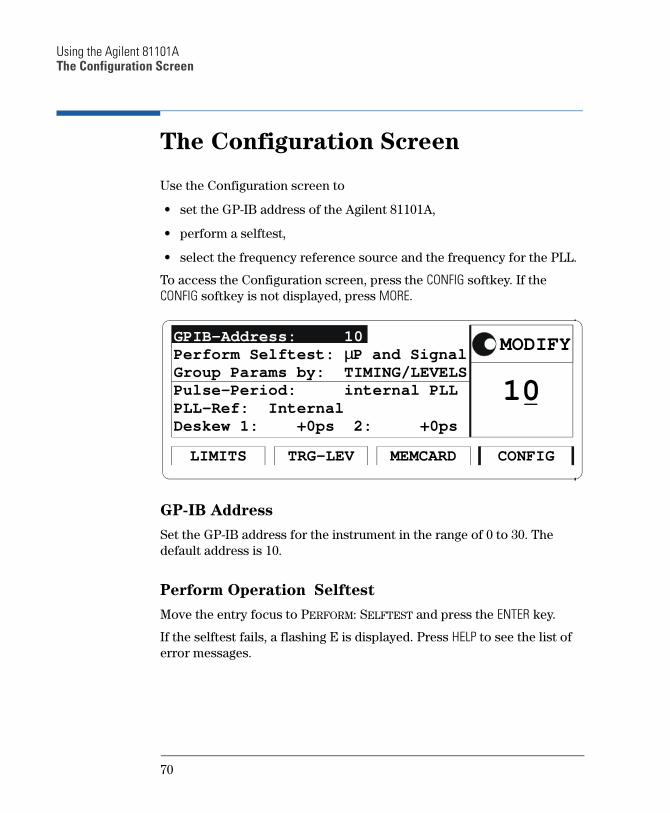
The Configuration Screen
Use the Configuration screen to
set the GP-IB address of the Agilent 81101A,
perform a selftest,
select the frequency reference source and the frequency for the PLL.
To access the Configuration screen, press the CONFIG softkey. If the
CONFIG softkey is not displayed, press MORE.
GP-IB Address
Set the GP-IB address for the instrument in the range of 0 to 30. The
default address is 10.
Perform Operation Selftest
Move the entry focus to PERFORM: SELFTEST and press the ENTER key.
If the selftest fails, a flashing E is displayed. Press HELP to see the list of
error messages.
10
TRG-LEV CONFIGMEMCARDLIMITS
Pulse-Period: internal PLL
GPIB-Address: 10
Group Params by: TIMING/LEVELS
PLL-Ref: Internal
MODIFY
Deskew 1: +0ps 2: +0ps
Perform Selftest: µP and Signal
70
Using the Agilent 81101AThe Configuration Screen
PLL Reference
Set the frequency reference source for the PLL:
INTERNAL
The internal 5 MHz reference.
CLK-IN
An external reference signal at the CLOCK/REF INP. connector. You
can set the expected frequency of the external reference to 5 MHz or
10 MHz.
71
Using the Agilent 81101AWarnings and Errors
Warnings and Errors
The Agilent 81101A has two levels of error reporting called warnings
and errors. Checking for errors and warnings is always enabled, unless
you switch it off via the GP-IB using the :SYSTem:CHECk command.
A warning is generated when the output signal could be invalid due
to a combination of worst case uncertainties at the current settings of
all relevant parameters.
For example, when adjusting the pulse width, all other timing
parameters (leading edge, trailing edge, and pulse period) and their
uncertainties have to be considered in order to check if the width
setting will fits within the pulse period.
Note that the warning limits are therefore not fixed for a particular
parameter, but vary with the settings of the related parameters. It is
also possible that the error and warning limits are the same, that is, a
warning does not occur before the error limit is reached.
If a warning occurs, the settings are still implemented in the hardware
because the worst-case conditions used to evaluate the warning limits
are very unlikely to occur in practice.
A blinking W indicates that one or more warnings have occurred.
Press HELP to view the warning list.
An error is generated when an invalid mode is chosen, or the
required parameter settings cannot be implemented in the output
hardware. Multiple errors can occur, but only the first error detected
is displayed.
An error is indicated by a blinking error message at the bottom of the
screen.
NOTE If you are using the knob to adjust parameters it is normally not possible
to generate warnings or errors. All parameters are automatically limited
to settings that guarantee specified operation.
However, if you press the SHIFT key while turning the knob, you can
adjust a parameter beyond its warning limits.
72
Using the Agilent 81101AWarnings and Errors
NOTE You can press SHIFT + HELP (AUTOSET) to carry out an autoset. The
instrument resets all parameters, based on the current period setting, to
remove all warning and error conditions.
An Example of Warning and Error Reporting
1 Switch on the instrument and recall the standard settings by pressing
SHIFT + STORE (RECALL) + 0.
The period is now set to 1 µs.
2 Switch on the output by pressing SHIFT + 0 (ON/OFF).
3 On the Output screen, move the parameter cursor to the value of the
WIDTH parameter (100NS).
4 Use the knob to make the pulse width as large as possible
(approximately 940NS).
This limit is intended to guarantee that the actual output pulse is
within specifications, for the actual period.
The limit is calculated taking into account a worst case combination
of minimum period from the period setting (1 µS) and maximum
width from the width setting (940 NS) together with minimum leading
and trailing edge settings (5.00 NS).
NOTE Note that if you now try to adjust the leading edge from its current
setting of 5.00 ns with the knob, it cannot be adjusted. This is because the
upper and lower warning limits are currently 5.00 ns. The width is at its
maximum value and width + leading edge + trailing edge < period.
5 Press SHIFT and adjust the pulse width above its warning limit. A
flashing W appears to indicate that a warning condition has occurred.
NOTE Note that as long as no errors occur, the output hardware is set up and
attempts to generate the required output.
6 Press HELP to see the warning message:
TRAILING EDGE 1 MAY CUT NEXT PULSE
7 Press HELP again to return to the WIDTH parameter.
73

Using the Agilent 81101AWarnings and Errors
8 Increase the pulse width further to approximately 980 ns and press
HELP to see the current warnings:
WIDTH 1 TOO CLOSE TO PERIOD
TRAILING EDGE 1 MAY CUT NEXT PULSE
9 Press HELP again to return to the WIDTH parameter.
10 Increase the pulse width further until a flashing error message
appears (approximately 1.10 µs):
OUTPUT 1: WIDTH > PERIOD
You have reached the current upper error-limit of the WIDTH
parameter.
The setting is not implemented in the output hardware.
11 Press SHIFT + HELP to perform an AUTOSET.
74

A AInstallation & Maintenance
75
Initial Inspection
Initial Inspection
Inspect the shipping container for damage. If the container or cushioning material is damaged, keep it until the contents of the shipment have been checked for completeness and the instrument has been verified both mechanically and electrically.
WA RNING To avoid hazardous electric shock, do not perform electrical tests
when there are signs of shipping damage to any part of the
instruments outer covers or panels.
If the contents are incomplete, or there is mechanical damage, or if the instrument does not work as expected within its specifications, notify the nearest Agilent office. (Please request the latest performance tests from Agilent.) Keep the shipping materials for inspection by the carrier. The Agilent office will arrange for repair or replacement without awaiting settlement.
76
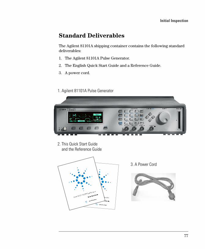
Initial Inspection
Standard Deliverables
The Agilent 81101A shipping container contains the following standard deliverables:
1. The Agilent 81101A Pulse Generator.
2. The English Quick Start Guide and a Reference Guide.
3. A power cord.
1. Agilent 81101A Pulse Generator
2. This Quick Start Guide
3. A Power Cord
and the Reference Guide
77
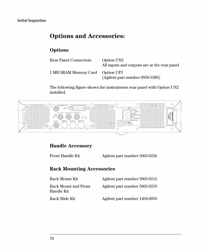
Initial Inspection
Options and Accessories:
Options
The following figure shows the instruments rear panel with Option UN2 installed.
Handle Accessory
Rack Mounting Accessories
Rear Panel Connectors Option UN2All inputs and outputs are at the rear panel
1 MB SRAM Memory Card Option UFJ(Agilent part number 0950-3380)
Front Handle Kit Agilent part number 5063-9226
Rack Mount Kit Agilent part number 5063-9212
Rack Mount and Front Handle Kit
Agilent part number 5063-9219
Rack Slide Kit Agilent part number 1494-0059
78
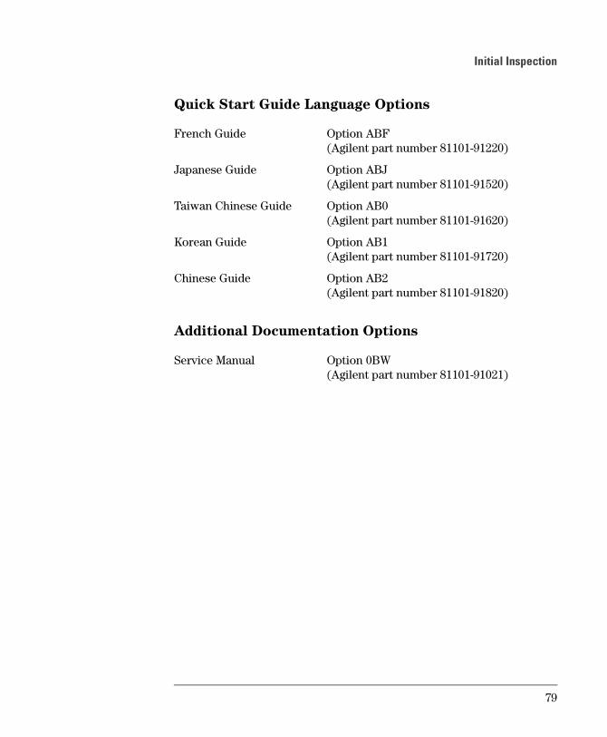
Initial Inspection
Quick Start Guide Language Options
Additional Documentation Options
French Guide Option ABF(Agilent part number 81101-91220)
Japanese Guide Option ABJ(Agilent part number 81101-91520)
Taiwan Chinese Guide Option AB0(Agilent part number 81101-91620)
Korean Guide Option AB1(Agilent part number 81101-91720)
Chinese Guide Option AB2(Agilent part number 81101-91820)
Service Manual Option 0BW(Agilent part number 81101-91021)
79
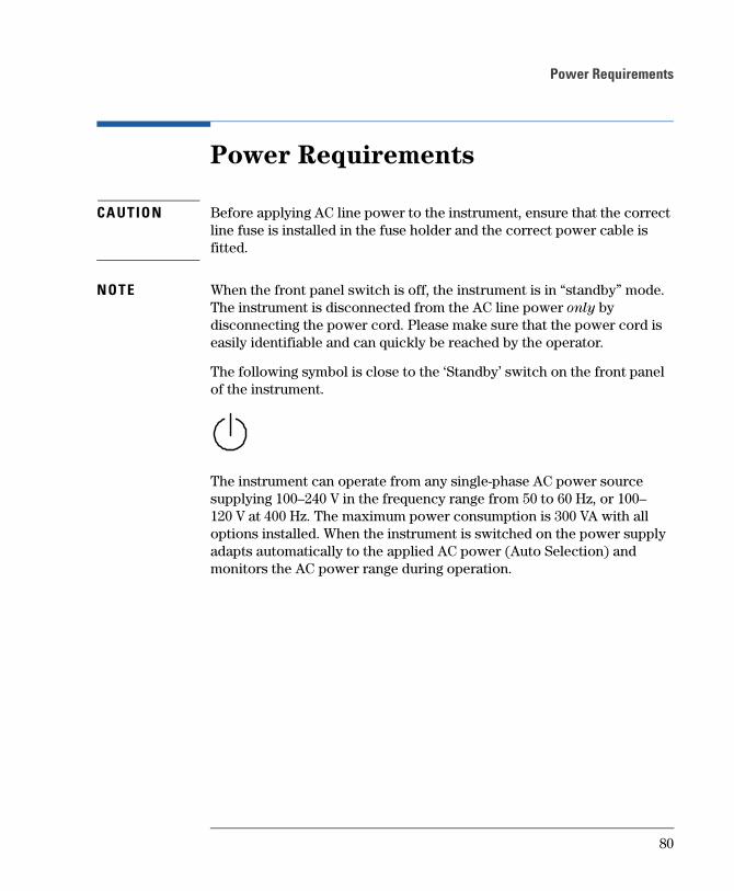
Power Requirements
Power Requirements
CA UTIO N Before applying AC line power to the instrument, ensure that the correct line fuse is installed in the fuse holder and the correct power cable is fitted.
NOTE When the front panel switch is off, the instrument is in “standby” mode. The instrument is disconnected from the AC line power only by disconnecting the power cord. Please make sure that the power cord is easily identifiable and can quickly be reached by the operator.
The following symbol is close to the ‘Standby’ switch on the front panel of the instrument.
The instrument can operate from any single-phase AC power source supplying 100–240 V in the frequency range from 50 to 60 Hz, or 100–120 V at 400 Hz. The maximum power consumption is 300 VA with all options installed. When the instrument is switched on the power supply adapts automatically to the applied AC power (Auto Selection) and monitors the AC power range during operation.
80
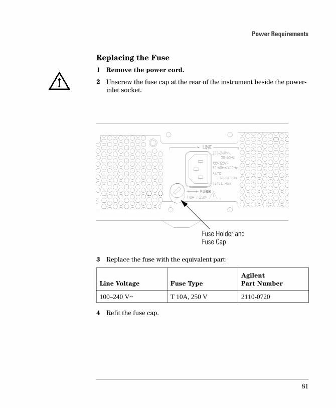
Power Requirements
Replacing the Fuse
1 Remove the power cord.
2 Unscrew the fuse cap at the rear of the instrument beside the power-inlet socket.
3 Replace the fuse with the equivalent part:
4 Refit the fuse cap.
Fuse Holder andFuse Cap
Line Voltage Fuse Type
Agilent
Part Number
100–240 V~ T 10A, 250 V 2110-0720
81
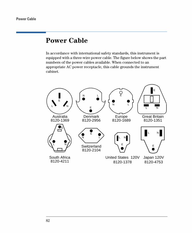
Power Cable
Power Cable
In accordance with international safety standards, this instrument is equipped with a three-wire power cable. The figure below shows the part numbers of the power cables available. When connected to an appropriate AC power receptacle, this cable grounds the instrument cabinet.
Denmark8120-2956
Europe8120-1689
Great Britain8120-1351
L
E
N
N LL N
E
E
Australia8120-1369
L
E
N
South Africa8120-4211
NL
E
Switzerland8120-2104
LNE
E
L N
United States 120V8120-1378
E
L N
Japan 120V8120-4753
82
Ventilation Requirements
Ventilation Requirements
The instrument is fitted with three cooling fans. Make sure that there is adequate clearance of 80 mm at the rear and 25 mm at the top and bottom to ensure adequate air flow. If the air flow is restricted, the internal operating temperature will be higher, reducing the instrument's reliability or causing the instrument's thermal-protection circuits to automatically switch off the instrument.
NOTE Do not cover the ventilation holes.
Thermal Protection
Overheating Detection
The instrument monitors its internal temperature. If the temperature exceeds approximately 80°C, the power supply is switched off. The instrument will switch on again if the temperature falls below approximately 77°C.
Fan Failure
If a fan is broken or prevented from operating by a blockage, the temperature will increase. When the temperature exceeds approximately 80°C the overheating detection switches off the instrument for safety reasons. For reliability it is recommended to send instruments with broken or defective fans immediately to Agilent Service for repair.
83
Battery
Battery
This instrument contains a lithium battery. Typical life time of the battery is about 5 years.
NOTE Recycle or dispose used batteries according to local regulations. Or contact your Agilent representative for information on battery recycling.
The battery is replaceable. Replacement should only be carried out by qualified service personnel.
NOTE There is a danger of explosion if the battery is incorrectly replaced.
The battery must be replaced with the same or equivalent battery type:
A Lithium CR2477-N type battery.
The Agilent replacement part number is: 1420-0557.
The battery is protected against charging.
CA UTIO N Do not crush, puncture, or incinerate the battery. Do not short the battery’s external contacts.
84

Battery
Battery Replacement
NOTE Disconnect the power cord from AC line voltage to avoid electrical shock.
1 Remove the bumper which is fitted to the front panel.
2 Remove the strips on the left and right side of the front panel.
3 Remove the front panel which is secured with two screws at each side.
4 Disconnect the flat cable which connects the front panel to the chassis.
5 On the right side of the chassis there is a cover secured with one screw. Remove this cover.
6 Now the battery can be removed from the battery holder. It is recommended to push the battery on the top, and to pull the battery on the bottom with one finger for easier removal.
7 Fit the new battery in the holder, take care to not short current the battery on the chassis.
8 Fit the cover again and secure it with the screw to the chassis.
9 Re-connect the flat cable of the front panel again to the chassis connector. Make sure that the pin one (red wire) is pointing to the mid of the chassis.
10 Re-assemble the front cover.
11 Fit the strips to the sides of the front panel, again.
12 Fit the bumper to the front panel.
85
Operating Environment
Operating Environment
WA RNING The instrument is not designed for outdoor use. Do not expose
the instrument to rain or other excessive moisture. Protect the
instrument from humidity and temperature changes which could
cause condensation within the instrument.
Do not operate the instrument in the presence of flammable
gases, fumes or powders. Operation of any electrical instrument
in such an environment constitutes a definite safety hazard.
Storage Temperature –40 °C to +70 °C
Operating Temperature 0 °C to 55 °C
Humidity 95% R.H. (at 40 °C)
Altitude Up to 2000m
Installation Category II
Pollution Degree 2
86
Cleaning Recommendation
Cleaning Recommendation
WA RNING To prevent electrical shock, disconnect the instrument from
mains before cleaning. Use a dry cloth or one slightly dampened
with water to clean external case parts. Do not attempt to clean
internally.
87

Acoustic Noise Emission
Acoustic Noise Emission
Acoustic Noise Emission
For ambient temperatures up to 30°C, under normal operation and at the typical operator position:
LpA = 52 dBA
Measured in accordance with ISO 7779 / EN 27779.
Geräuschemissionswerte
Bei einer Umgebungstemperatur bis 30°C
LpA = 52 dBA
am Arbeitsplatz, normaler Betrieb.
Angabe ist das Ergebnis einer Typprüfung nach ISO 7779 / EN 27779.
88
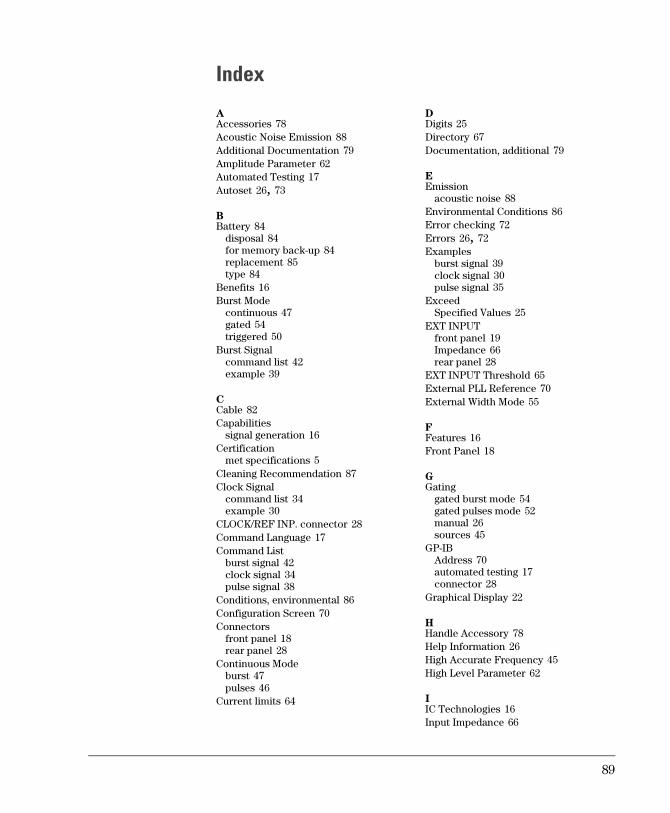
Index
AAccessories 78Acoustic Noise Emission 88Additional Documentation 79Amplitude Parameter 62Automated Testing 17Autoset 26, 73
BBattery 84
disposal 84for memory back-up 84replacement 85type 84
Benefits 16Burst Mode
continuous 47gated 54triggered 50
Burst Signalcommand list 42example 39
CCable 82Capabilities
signal generation 16Certification
met specifications 5Cleaning Recommendation 87Clock Signal
command list 34example 30
CLOCK/REF INP. connector 28Command Language 17Command List
burst signal 42clock signal 34pulse signal 38
Conditions, environmental 86Configuration Screen 70Connectors
front panel 18rear panel 28
Continuous Modeburst 47pulses 46
Current limits 64
DDigits 25Directory 67Documentation, additional 79
EEmission
acoustic noise 88Environmental Conditions 86Error checking 72Errors 26, 72Examples
burst signal 39clock signal 30pulse signal 35
ExceedSpecified Values 25
EXT INPUTfront panel 19Impedance 66rear panel 28
EXT INPUT Threshold 65External PLL Reference 70External Width Mode 55
FFeatures 16Front Panel 18
GGating
gated burst mode 54gated pulses mode 52manual 26sources 45
GP-IBAddress 70automated testing 17connector 28
Graphical Display 22
HHandle Accessory 78Help Information 26High Accurate Frequency 45High Level Parameter 62
IIC Technologies 16Input Impedance 66
89
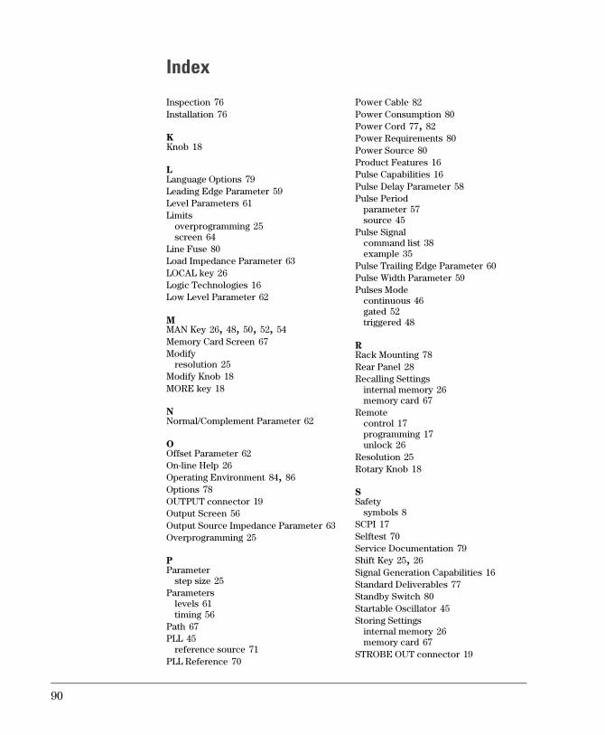
Index
Inspection 76Installation 76
KKnob 18
LLanguage Options 79Leading Edge Parameter 59Level Parameters 61Limits
overprogramming 25screen 64
Line Fuse 80Load Impedance Parameter 63LOCAL key 26Logic Technologies 16Low Level Parameter 62
MMAN Key 26, 48, 50, 52, 54Memory Card Screen 67Modify
resolution 25Modify Knob 18MORE key 18
NNormal/Complement Parameter 62
OOffset Parameter 62On-line Help 26Operating Environment 84, 86Options 78OUTPUT connector 19Output Screen 56Output Source Impedance Parameter 63Overprogramming 25
PParameter
step size 25Parameters
levels 61timing 56
Path 67PLL 45
reference source 71PLL Reference 70
Power Cable 82Power Consumption 80Power Cord 77, 82Power Requirements 80Power Source 80Product Features 16Pulse Capabilities 16Pulse Delay Parameter 58Pulse Period
parameter 57source 45
Pulse Signalcommand list 38example 35
Pulse Trailing Edge Parameter 60Pulse Width Parameter 59Pulses Mode
continuous 46gated 52triggered 48
RRack Mounting 78Rear Panel 28Recalling Settings
internal memory 26memory card 67
Remotecontrol 17programming 17unlock 26
Resolution 25Rotary Knob 18
SSafety
symbols 8SCPI 17Selftest 70Service Documentation 79Shift Key 25, 26Signal Generation Capabilities 16Standard Deliverables 77Standby Switch 80Startable Oscillator 45Storing Settings
internal memory 26memory card 67
STROBE OUT connector 19
90
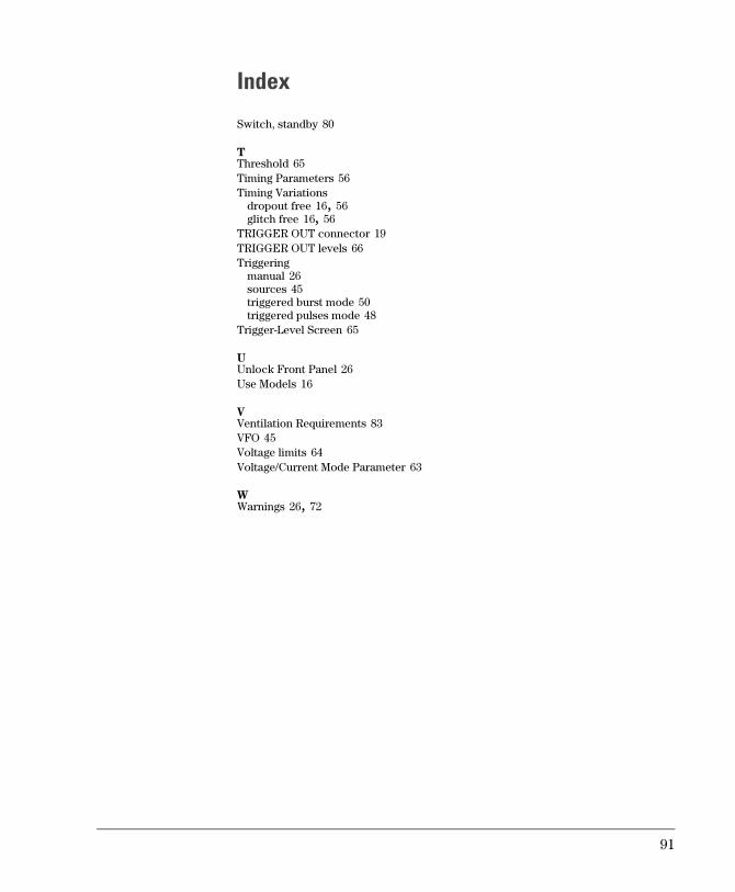
Index
Switch, standby 80
TThreshold 65Timing Parameters 56Timing Variations
dropout free 16, 56glitch free 16, 56
TRIGGER OUT connector 19TRIGGER OUT levels 66Triggering
manual 26sources 45triggered burst mode 50triggered pulses mode 48
Trigger-Level Screen 65
UUnlock Front Panel 26Use Models 16
VVentilation Requirements 83VFO 45Voltage limits 64Voltage/Current Mode Parameter 63
WWarnings 26, 72
91

Index
92
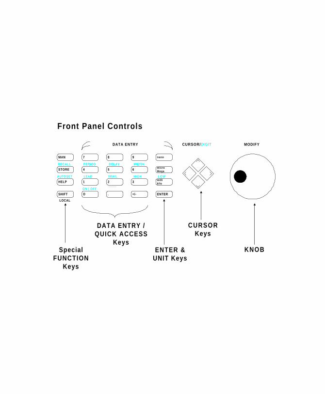
7
4
8 9
5 6
1 2 3
O . +/-
nano
microMega
millikilo
ENTER
MAN
STORE
HELP
SHIFT
DATA ENTRY CURSOR/DIGIT MODIFY
LOCAL
AUTOSET
RECALL PERIOD DELAY WIDTH
LEAD TRAIL HIGH LOW
ON | OFF
KNOB
CURSORKeys
ENTER &UNIT Keys
DATA ENTRY /QUICK ACCESS
KeysSpecial
FUNCTIONKeys
Front Panel Controls

Copyright Agilent Technologies 1998, 2000
Edition E0300
Printed in Germany
81101-91020