Regression Discontinuity Design 1. 2 Z Pr(X i =1 | z) 0 1 Z0Z0 Fuzzy Design Sharp Design.
Rock Slope Stability Analysis: Limit Equilibrium Method
•Plane failure analysis
•Wedge failure analysis
•Toppling failure analysis
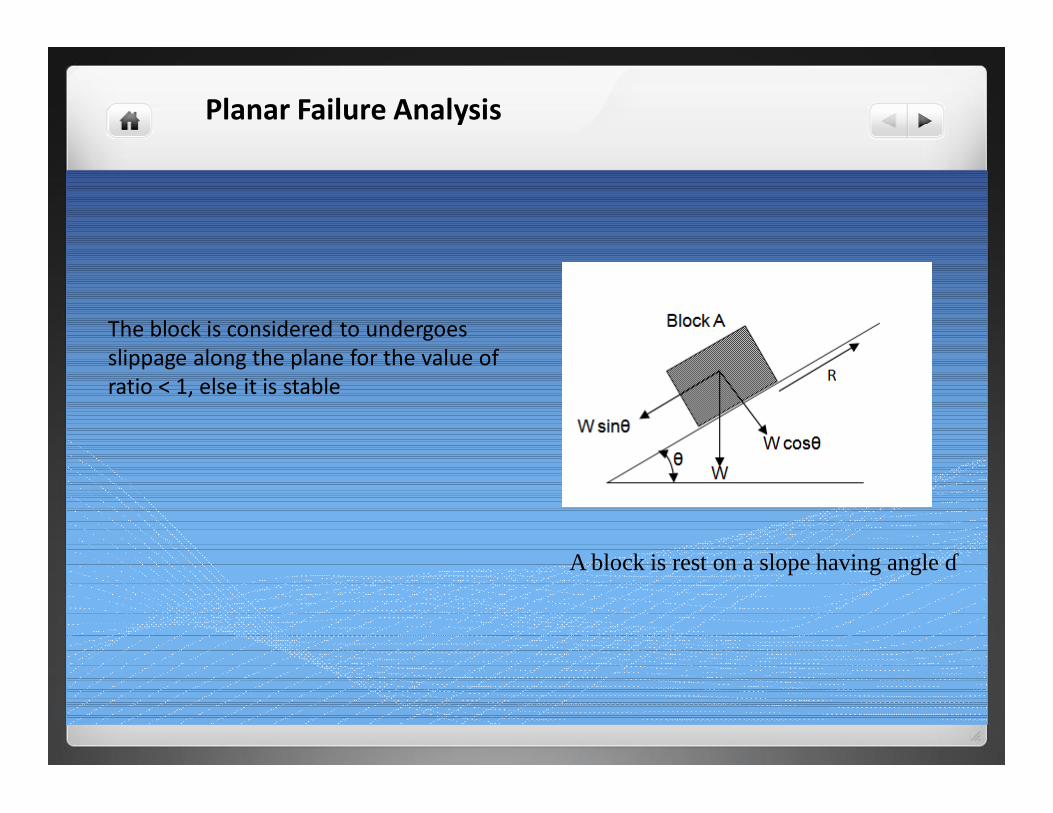
Planar Failure Analysis
A block is rest on a slope having angle θ
The block is considered to undergoes slippage along the plane for the value of ratio < 1, else it is stable
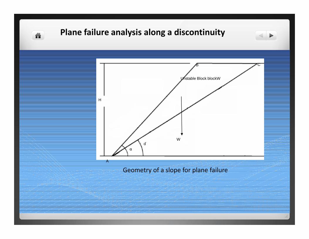
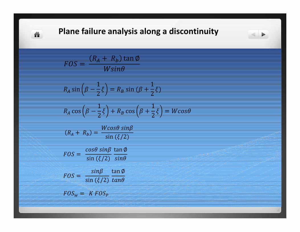
Plane failure analysis along a discontinuity
θ
A
B C
H
Unstable Block blockW
α
W
Geometry of a slope for plane failure
Plane failure analysis along a discontinuity
Planar Failure Analysis
• the plane on which sliding occurs must strike parallel or nearly parallel (within approximately + 200 ) to the slope face
• the failure must daylight in the slope face. This means that its dip must be smaller than the dip of the slope face
• the dip of the failure plane must be greater than the angle of internal friction angle of this plane
Plane failure analysis along a discontinuity
W cosθW
W sinθ
R
Block A
sShearStresgthShearStren
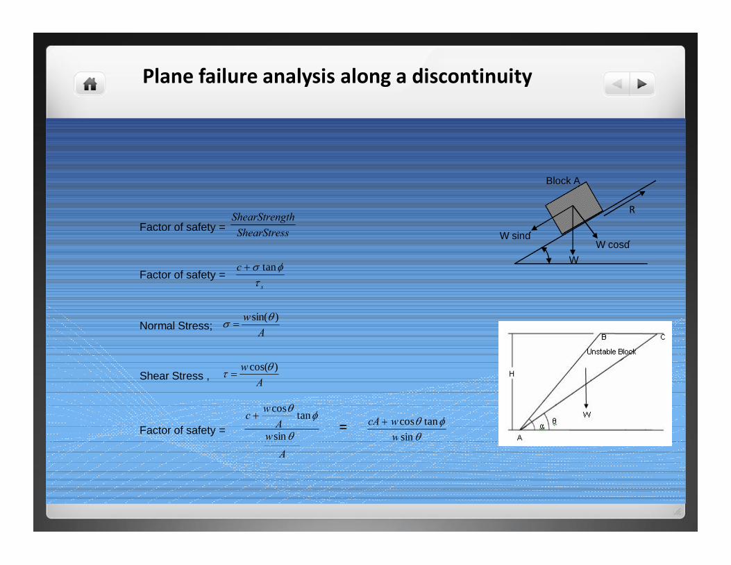
Factor of safety =
s
cτ
φσ tan+Factor of safety =
Aw
Awc
θ
φθ
sin
tancos+
θφθ
sintancos
wwcA +
Factor of safety = =
Aw )sin(θσ =Normal Stress;
Aw )cos(θτ =Shear Stress ,
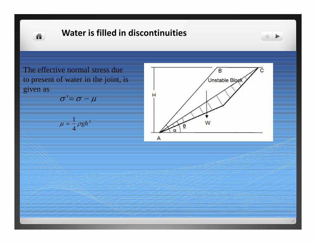
Water is filled in discontinuities
µσσ −='
2
41 ghρµ =
The effective normal stress due to present of water in the joint, is given as
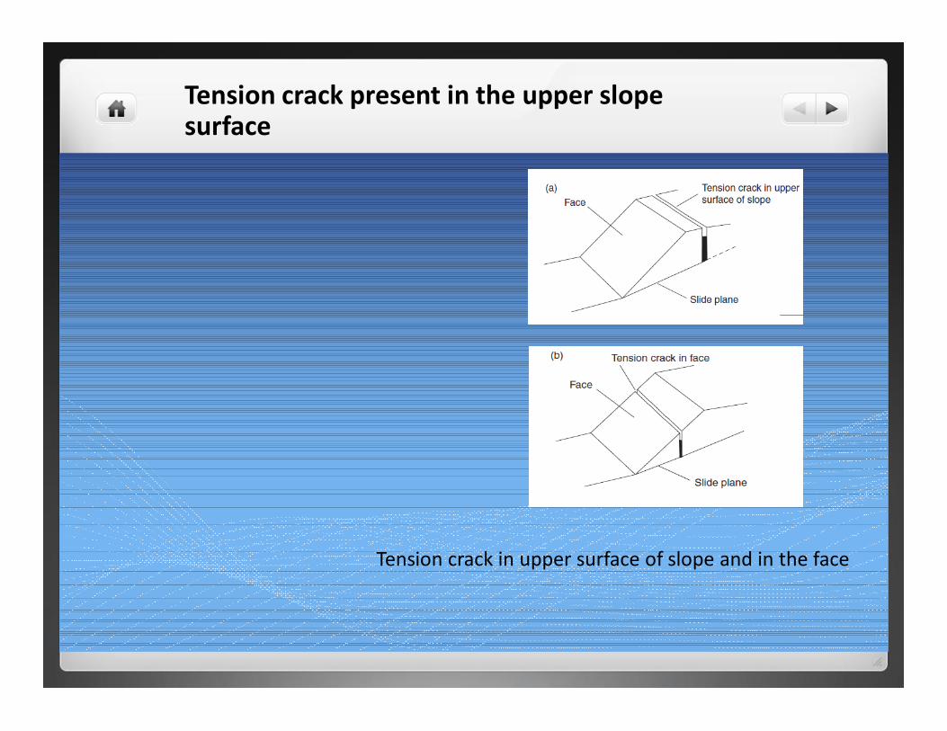
Tension crack present in the upper slope surface
Tension crack in upper surface of slope and in the face
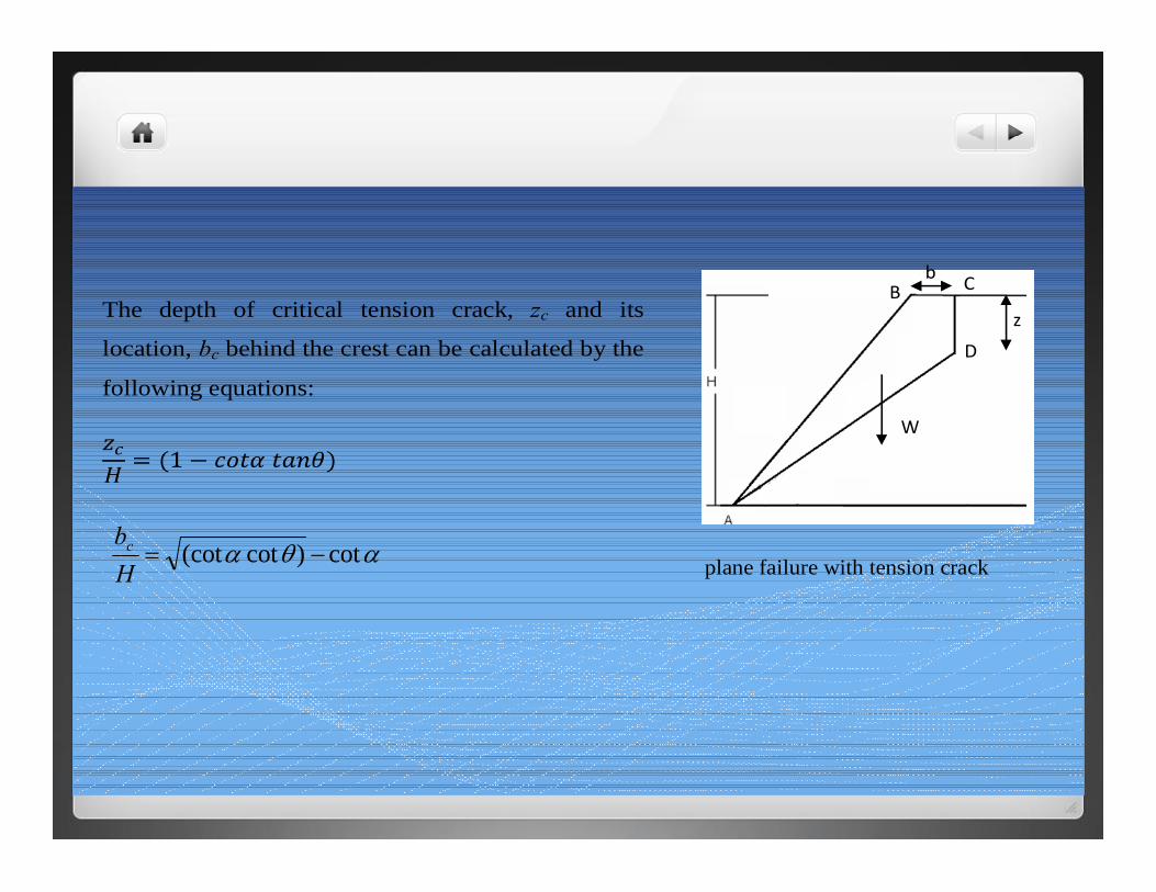
plane failure with tension crack
B
D
W
z
b C The depth of critical tension crack, zc and its
location, bc behind the crest can be calculated by the
following equations:
αθα cot)cot(cot −=Hbc
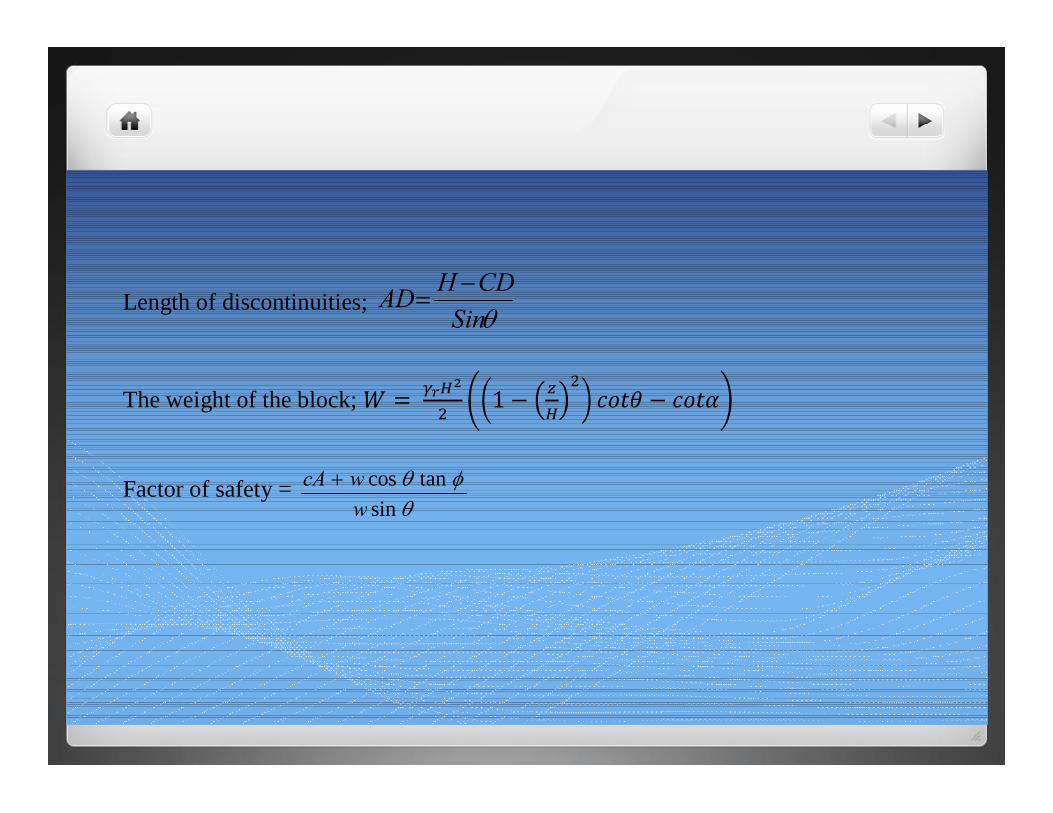
Length of discontinuities; θSinCDHAD −
=
The weight of the block;
Factor of safety = θ
φθsin
tancoswwcA +
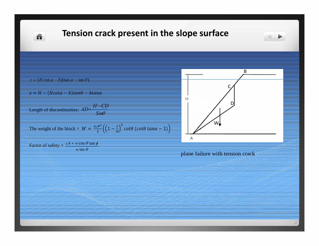
Tension crack present in the slope surface
plane failure with tension crack
B
C
D
W
)tan)(tancot( θαα −−= bHz
Length of discontinuities; θSinCDHAD −
=
The weight of the block =
Factor of safety = θ
φθsin
tancoswwcA +
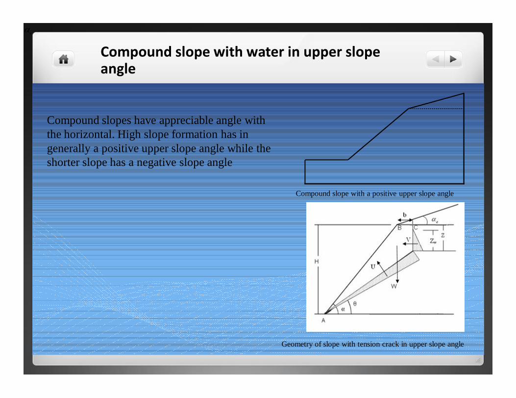
Compound slope with water in upper slope angle
Compound slope with a positive upper slope angle
Geometry of slope with tension crack in upper slope angle
cα
Compound slopes have appreciable angle with the horizontal. High slope formation has in generally a positive upper slope angle while the shorter slope has a negative slope angle
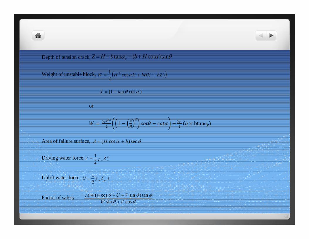
Depth of tension crack, θαα tan)cot(tan HbbHZ c +−+=
Weight of unstable block, ( ))cot21 2 bZbHXXHW ++= α
)cottan1( αθ−=X
or
Area of failure surface, θα sec)cot( bHA +=
Driving water force, 2
21
ww ZV γ=
Uplift water force, AZU wwγ21
=
Factor of safety = θθ
φθθcossin
tan)sincos(VW
VUwcA+
−−+

Effect of rock bolts
Geometry of slope with tension crack in upper slope and its interaction with rock bolt
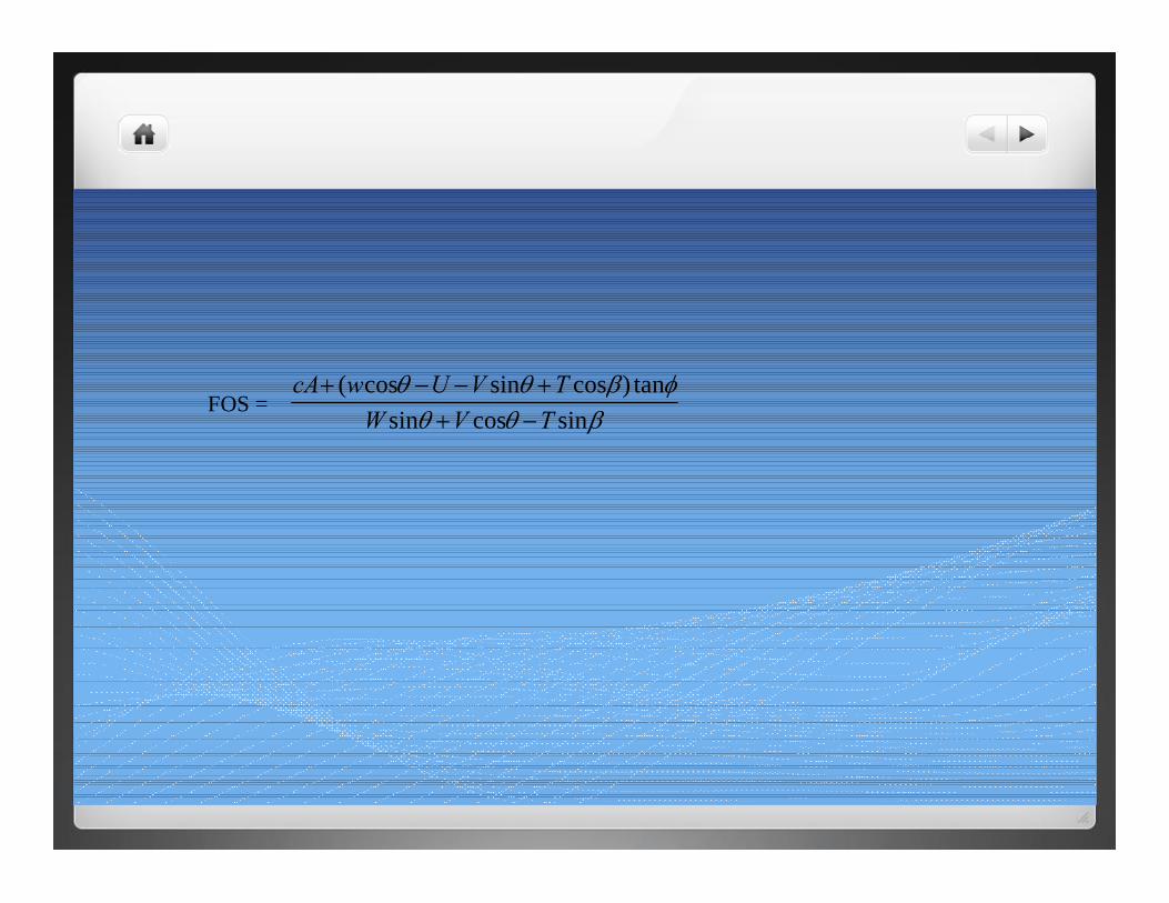
FOS = βθθ
φβθθsincossin
tan)cossincos(TVW
TVUwcA−+
+−−+
Wedge Failure Analysis
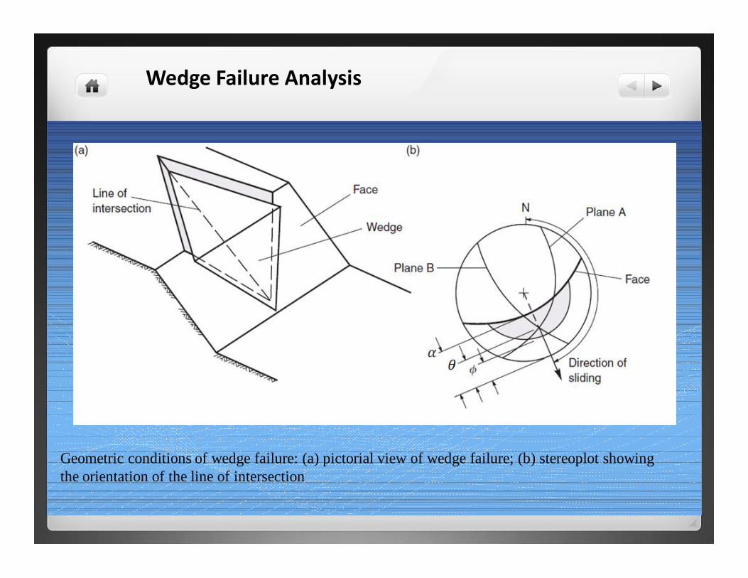
Geometric conditions of wedge failure: (a) pictorial view of wedge failure; (b) stereoplot showing the orientation of the line of intersection
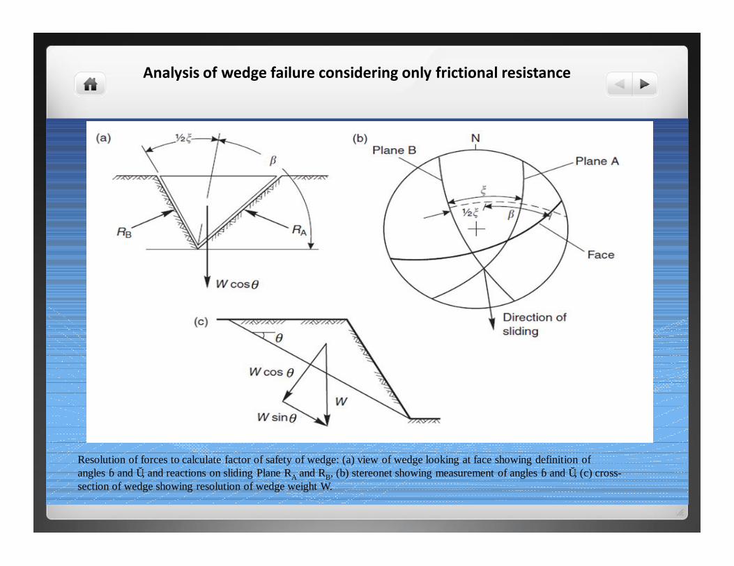
Analysis of wedge failure considering only frictional resistance
Resolution of forces to calculate factor of safety of wedge: (a) view of wedge looking at face showing definition of angles β and α, and reactions on sliding Plane RA and RB, (b) stereonet showing measurement of angles β and α, (c) cross-section of wedge showing resolution of wedge weight W.
Plane failure analysis along a discontinuity
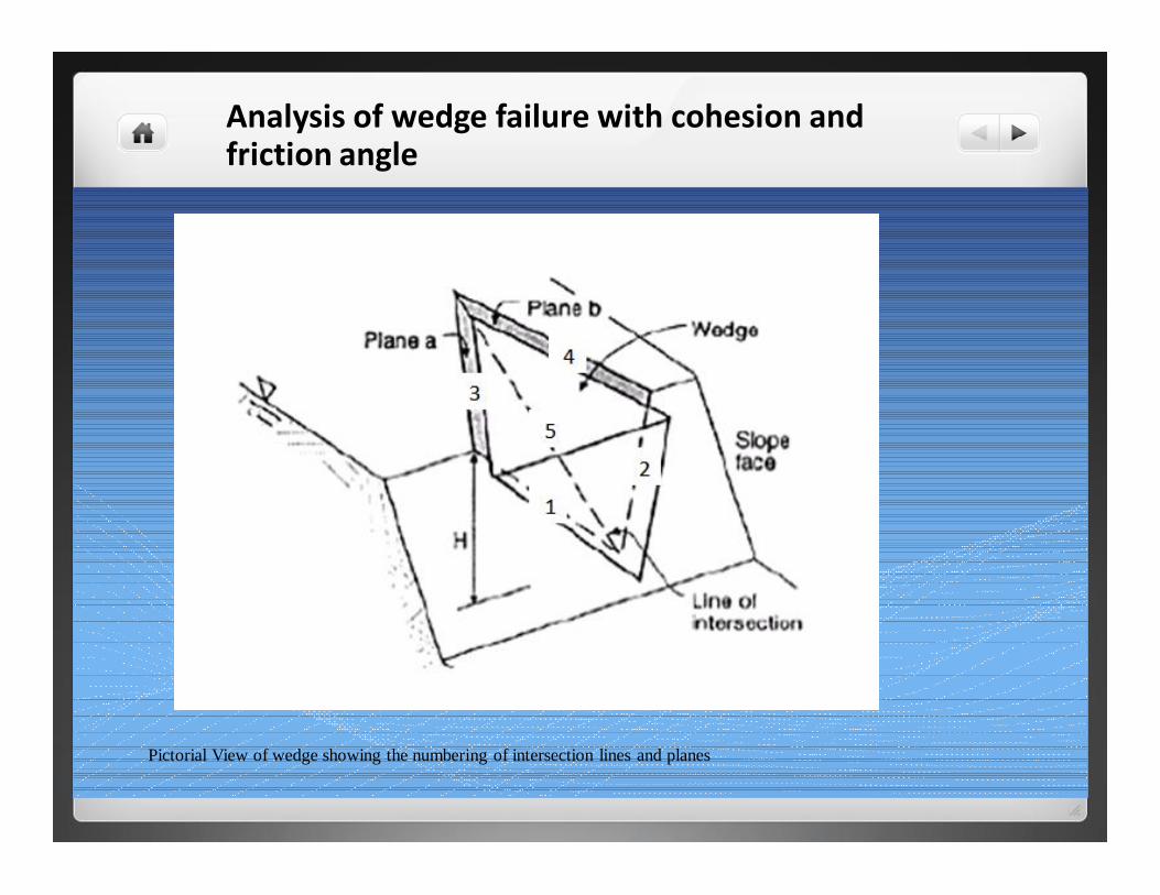
Analysis of wedge failure with cohesion and friction angle
Pictorial View of wedge showing the numbering of intersection lines and planes
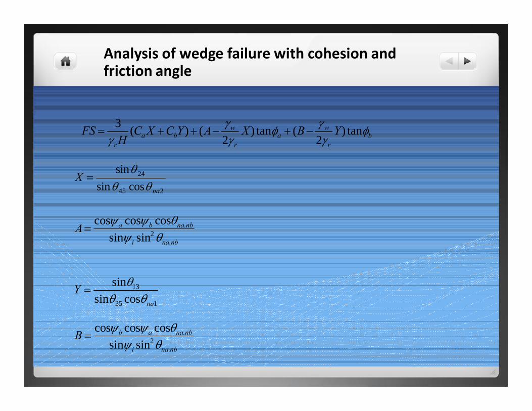
Analysis of wedge failure with cohesion and friction angle
br
wa
r
wba
r
YBXAYCXCH
FS φγ
γφγ
γγ
tan)2
(tan)2
()(3−+−++=
245
24
cossinsin
na
Xθθ
θ=
nbnai
nbnabaA.
2.
sinsincoscoscosθψ
θψψ=
135
13
cossinsin
na
Yθθ
θ=
nbnai
nbnaabB.
2.
sinsincoscoscosθψ
θψψ=
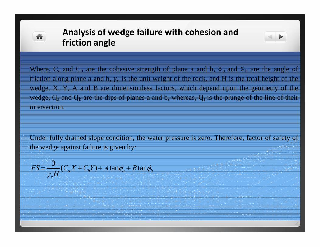
Analysis of wedge failure with cohesion and friction angle
Where, Ca and Cb are the cohesive strength of plane a and b, фa and фb are the angle of friction along plane a and b, is the unit weight of the rock, and H is the total height of the wedge. X, Y, A and B are dimensionless factors, which depend upon the geometry of the wedge, Ψa and Ψb are the dips of planes a and b, whereas, Ψi is the plunge of the line of their intersection.
Under fully drained slope condition, the water pressure is zero. Therefore, factor of safety of the wedge against failure is given by:
babar
BAYCXCH
FS φφγ
tantan)(3+++=
Toppling Failure Analysis
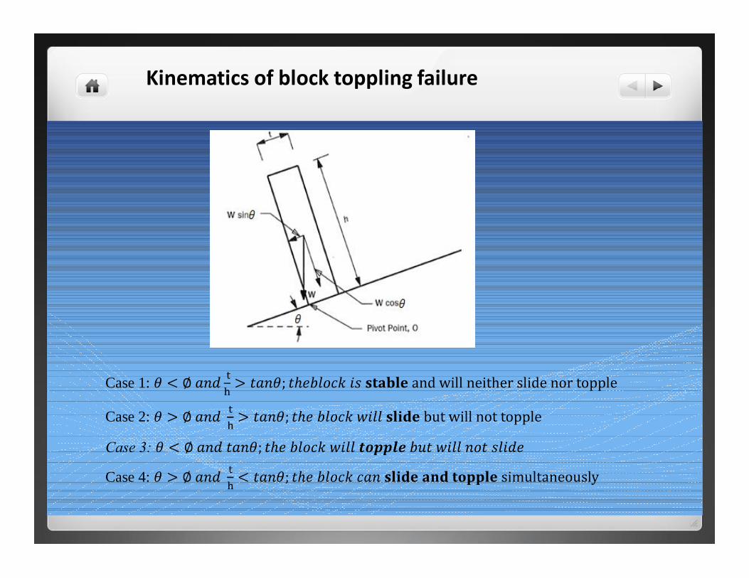
Kinematics of block toppling failure
Case 1:
Case 2:
Case 3:
Case 4:
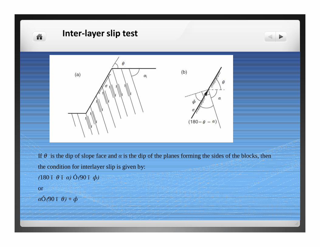
Inter-layer slip test
If is the dip of slope face and α is the dip of the planes forming the sides of the blocks, then
the condition for interlayer slip is given by:
(180 − − α) ≥ (90 − ф)
or
α≥ (90 − ) + ф
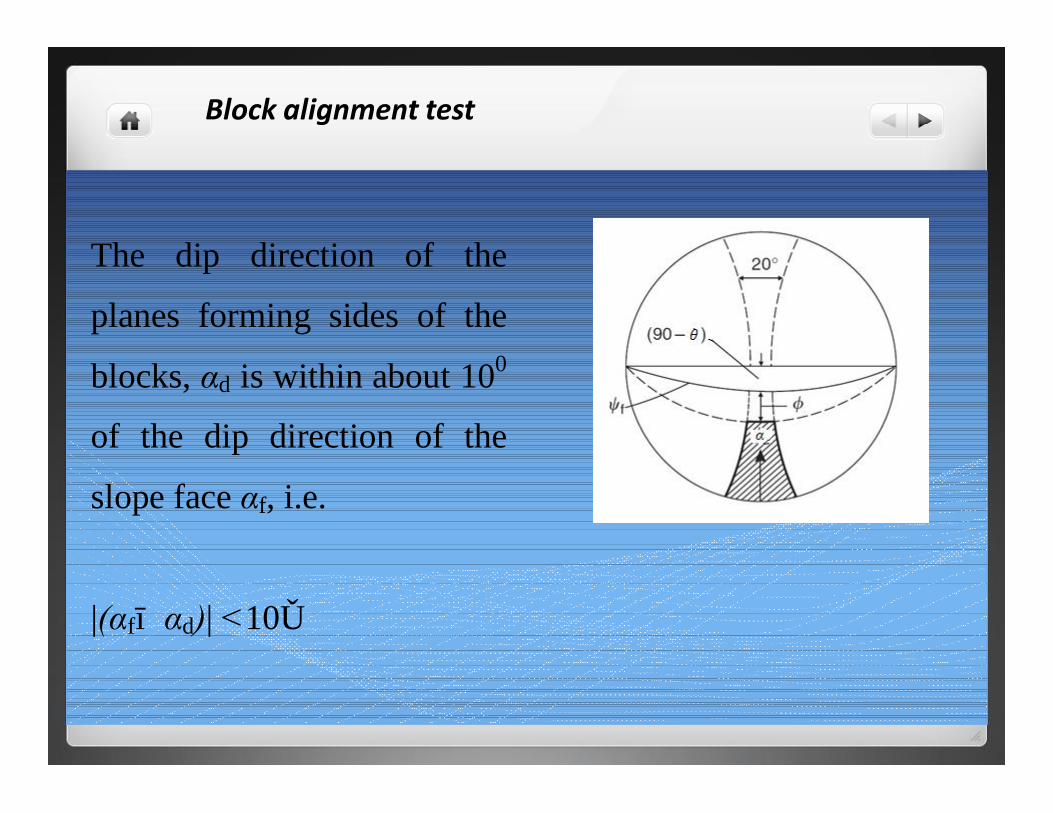
Block alignment test
The dip direction of the
planes forming sides of the
blocks, αd is within about 100
of the dip direction of the
slope face αf, i.e.
|(αf− αd)| <10◦
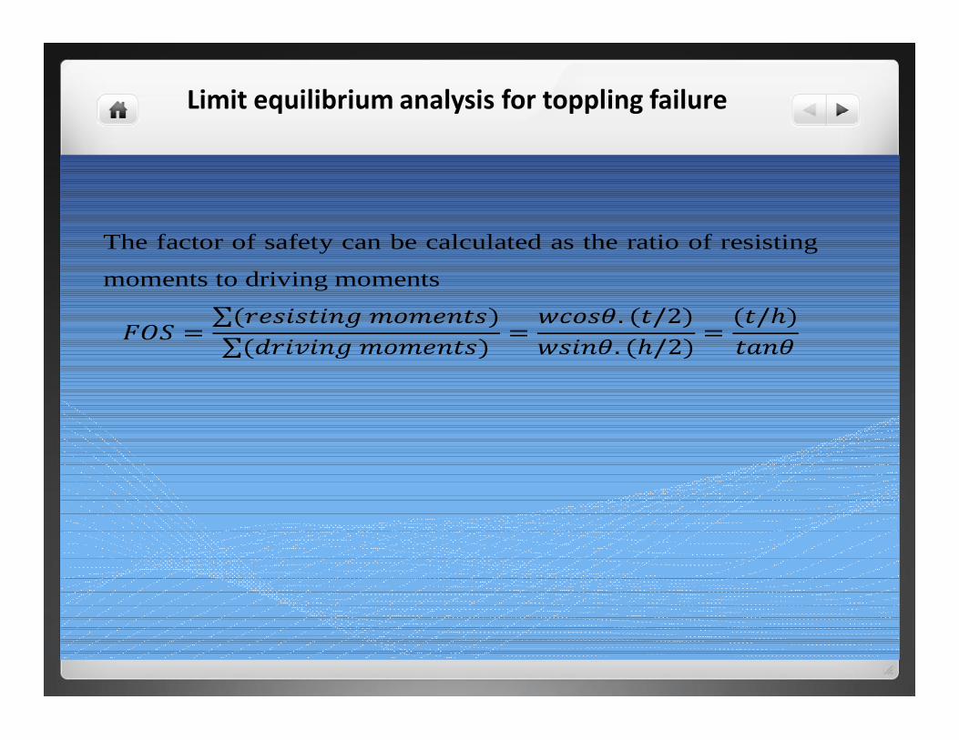
Limit equilibrium analysis for toppling failure
The factor of safety can be calculated as the ratio of resisting
moments to driving moments
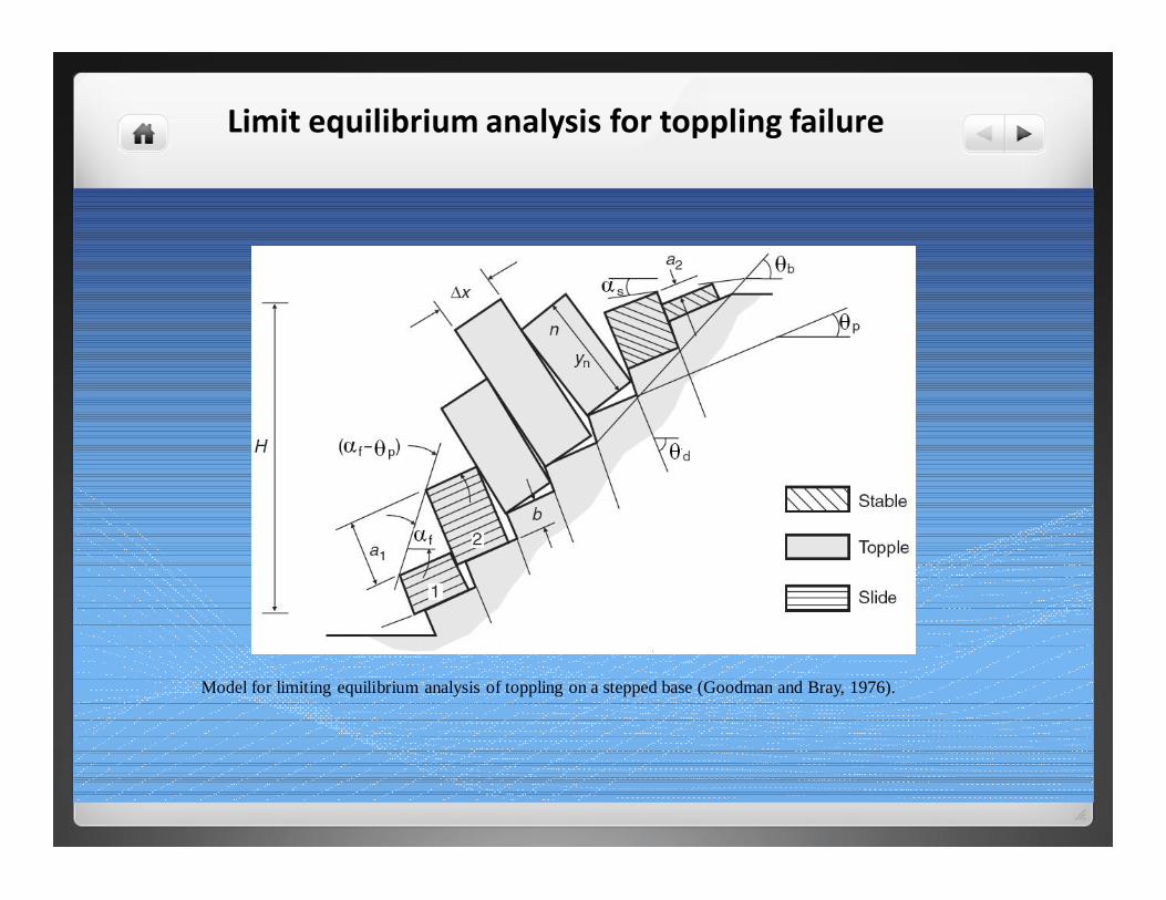
Limit equilibrium analysis for toppling failure
Model for limiting equilibrium analysis of toppling on a stepped base (Goodman and Bray, 1976).
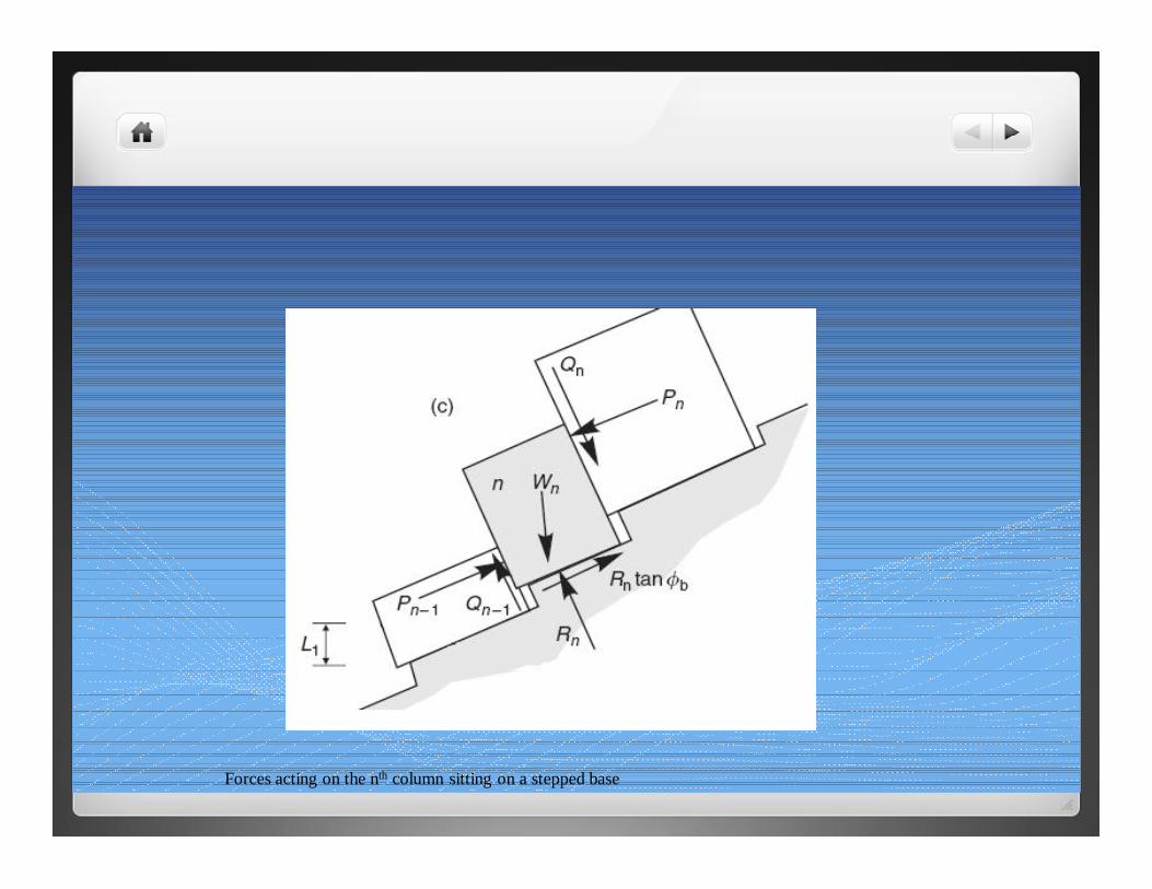
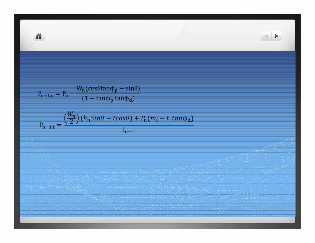
Forces acting on the nth column sitting on a stepped base
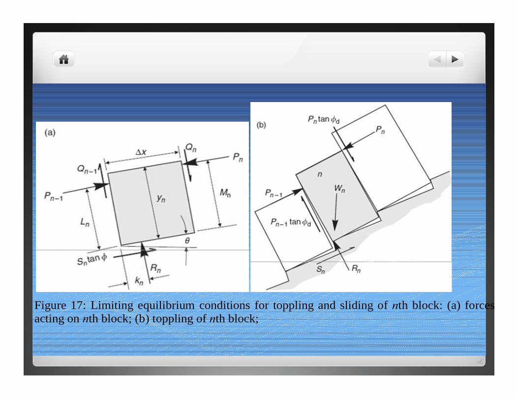
Figure 17: Limiting equilibrium conditions for toppling and sliding of nth block: (a) forces acting on nth block; (b) toppling of nth block;