REVIEW. Membrane Theory Calculation of R 1 and R 2 1.Cylindrate shell R 1 = ∞ R 2 = D / 2 δ D p.
44
REVIEW REVIEW
-
date post
21-Dec-2015 -
Category
Documents
-
view
222 -
download
0
Transcript of REVIEW. Membrane Theory Calculation of R 1 and R 2 1.Cylindrate shell R 1 = ∞ R 2 = D / 2 δ D p.

REVIEWREVIEW

Membrane TheoryMembrane Theory
Calculation of RCalculation of R11 and R and R22
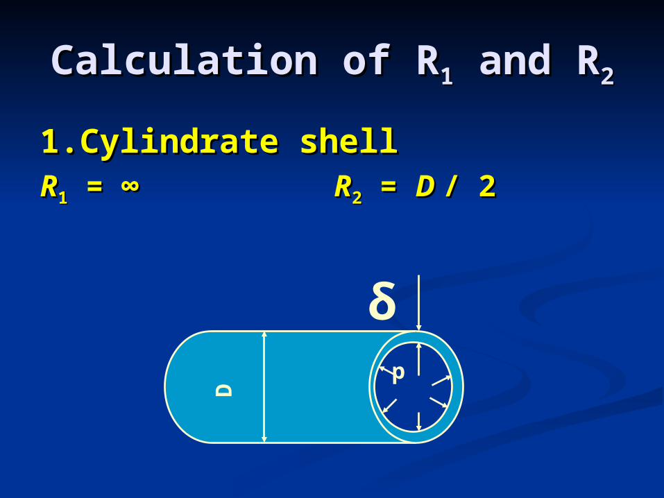
1.Cylindrate shell 1.Cylindrate shell RR11 = ∞ = ∞ RR22 = = D D / 2/ 2
δ
D
p
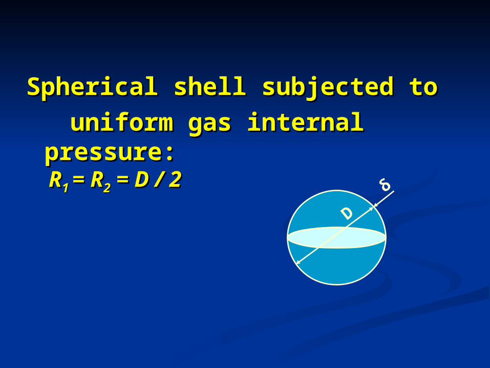
Spherical shell subjected to Spherical shell subjected to
uniform gas internal uniform gas internal pressure:pressure:
RR1 1 = R= R22 = D / 2 = D / 2
D
δ
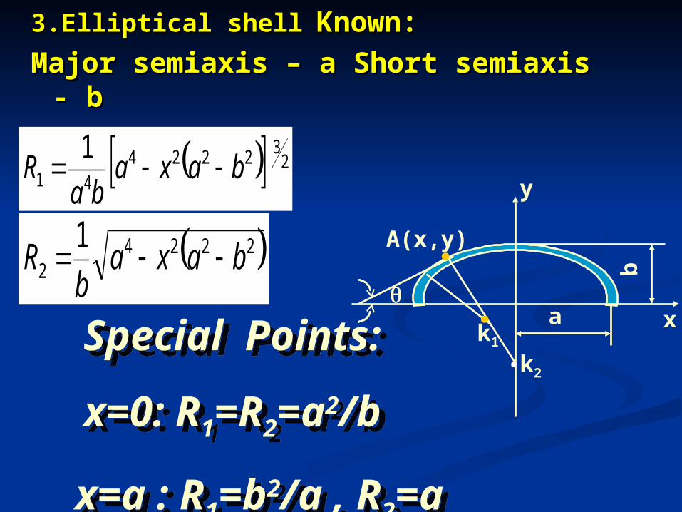
3.Elliptical shell3.Elliptical shell Known: Known: Major semiaxis – a Short semiaxis - bMajor semiaxis – a Short semiaxis - b
y
xa
b
A(x,y).
..
k2
k1
232224
41 1
baxaba
R
22242
1baxa
bR
Special Points:
x=0: R1=R2=a2/b
x=a : R1=b2/a , R2=a
Special Points:
x=0: R1=R2=a2/b
x=a : R1=b2/a , R2=a
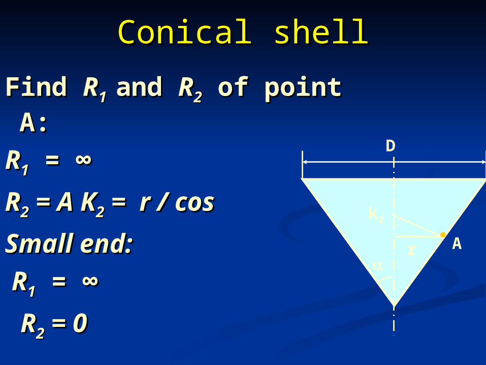
Conical shellConical shell
Find Find RR11 and and RR22 of point A: of point A: RR11 = = ∞∞ RR22 = A K = A K22 = r / cos = r / cosSmall end:Small end: RR11 = = ∞∞ RR22 = 0 = 0
D
r
.A
k2
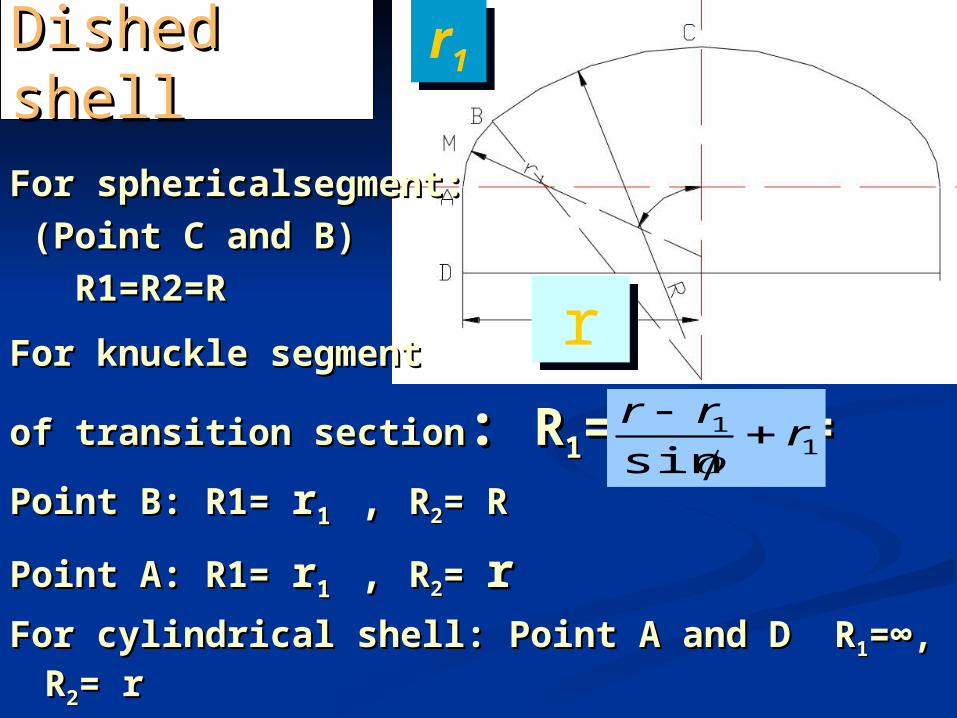
For sphericalsegment:For sphericalsegment: (Point C and B)(Point C and B) R1=R2=RR1=R2=R
For knuckle segmentFor knuckle segment of transition sectionof transition section: : RR11= r= r11, R, R22==Point B: R1= Point B: R1= rr1 1 , , RR22= R= R
Point A: R1= Point A: R1= rr1 1 , , RR22= = rrFor cylindrical shell: Point A and D RFor cylindrical shell: Point A and D R11=∞, R=∞, R22= r= r
Dished Dished shellshell
rr
r1r1
11
sinr
rr
2
2
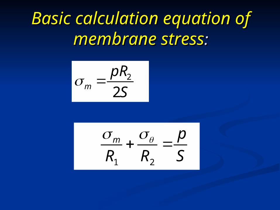
S
pRm
21 S
p
RRm
Basic calculation equation of Basic calculation equation of membrane stressmembrane stress::
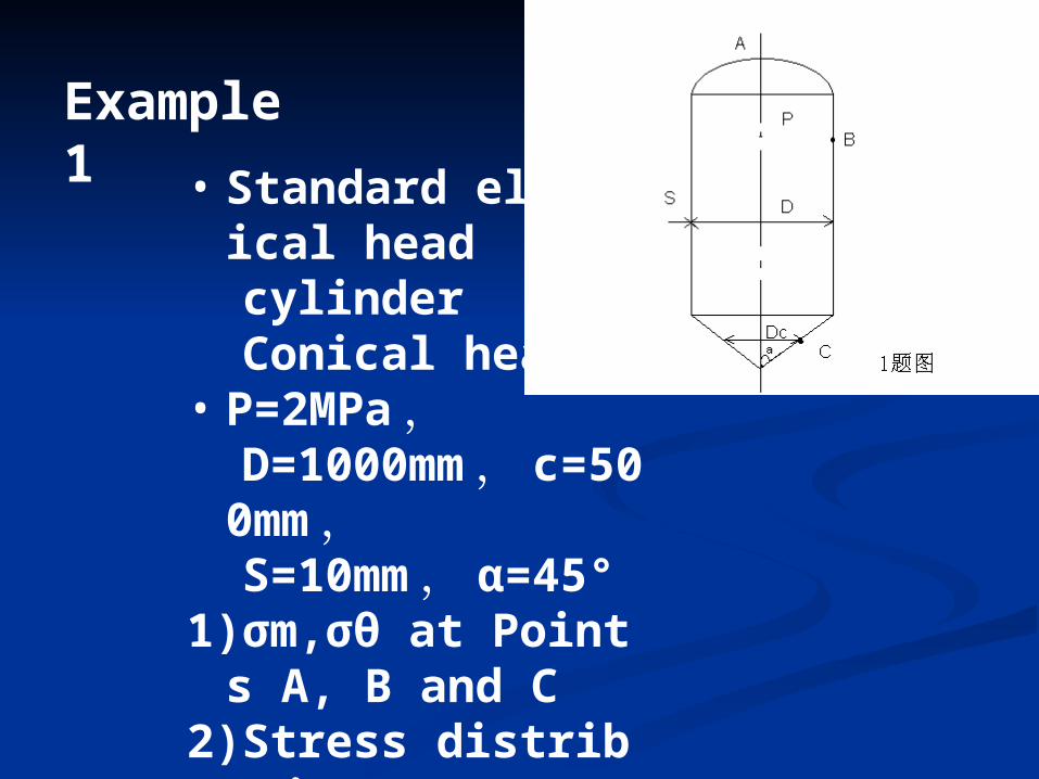
• Standard elliptical head
cylinder Conical head• P=2MPa , D=1000mm , c=5
00mm , S=10mm , α=45°1)σm,σθ at Points A,
B and C2)Stress distributio
n
Example 1
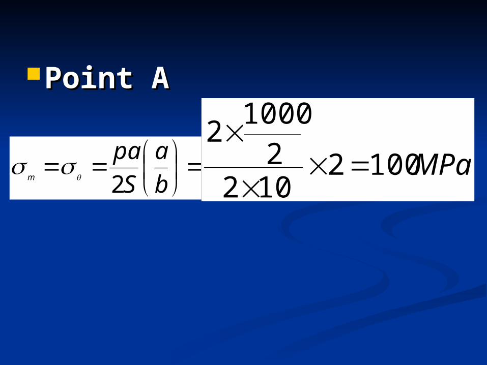
Point A Point A
b
a
S
pam 2
MPa10021022
10002
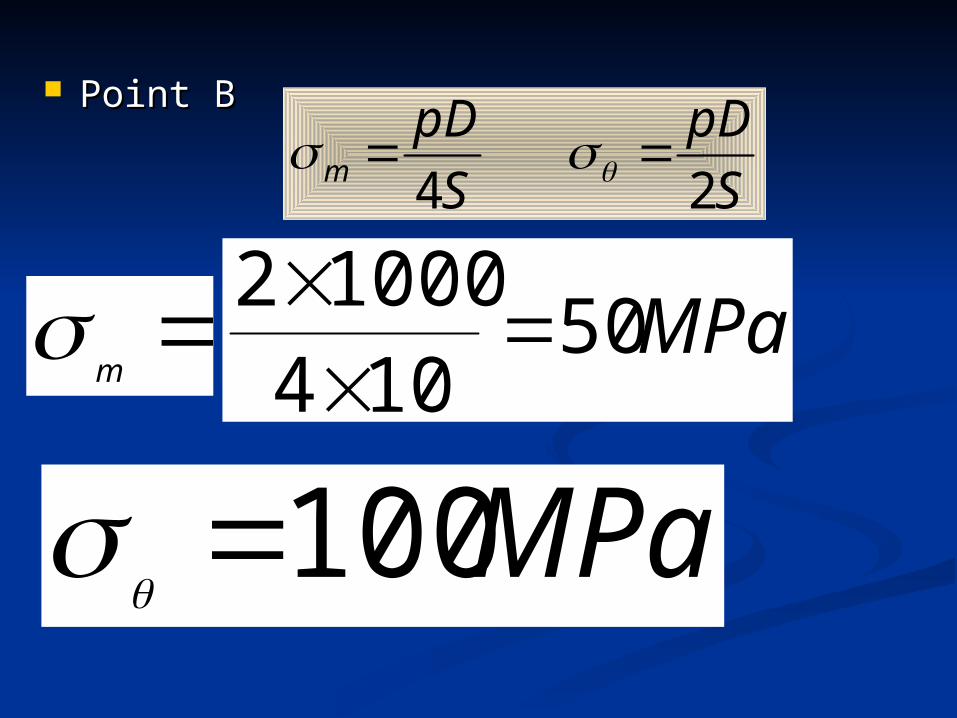
Point BPoint B
S
pD
S
pDm 2
4
m
MPa50104
10002
MPa100
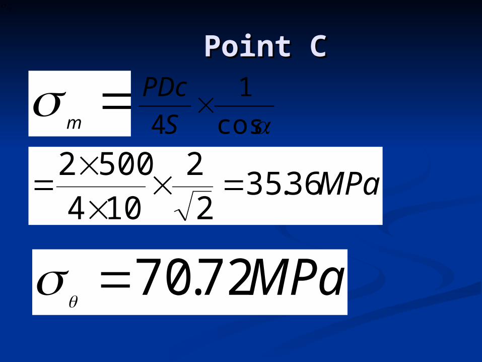
Point CPoint Cm
m
cos
1
4
S
PDc
MPa36.352
2
104
5002
MPa72.70
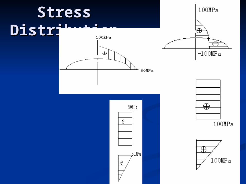
Stress Stress DistributionDistribution
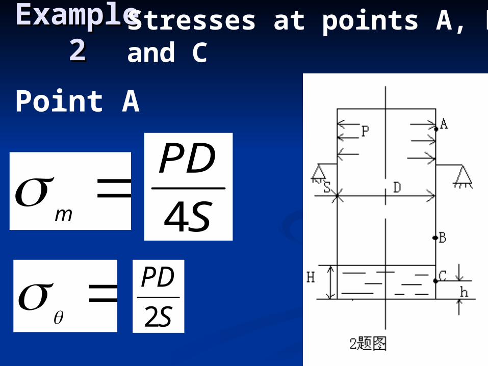
Example Example 22
Stresses at points A, B and C
m
S
PD
4
S
PD
2
Point A
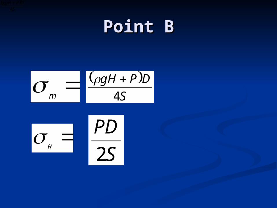
Point BPoint B
m
m
S
DPgH
4
S
DPgH
4
S
PD
2
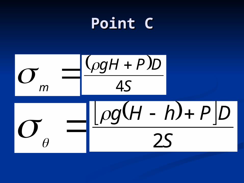
Point CPoint C
m
S
DPgH
4
S
DPhHg
2
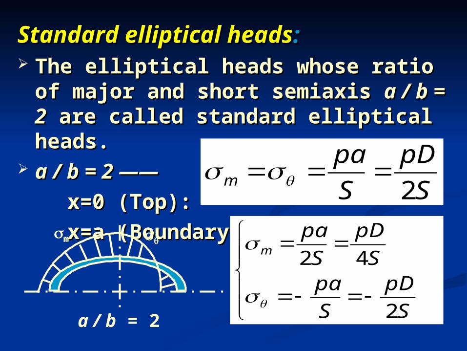
Standard elliptical headsStandard elliptical heads:: The elliptical heads whose ratio of majThe elliptical heads whose ratio of maj
or and short semiaxis or and short semiaxis a / b = 2a / b = 2 are calle are called standard elliptical heads.d standard elliptical heads.
a / b = 2 ——a / b = 2 —— x=0 (Top):x=0 (Top): x=a (Boundary):x=a (Boundary): S
pD
S
pam 2
2
42
S
pD
S
paS
pD
S
pam
m
a / b = 2
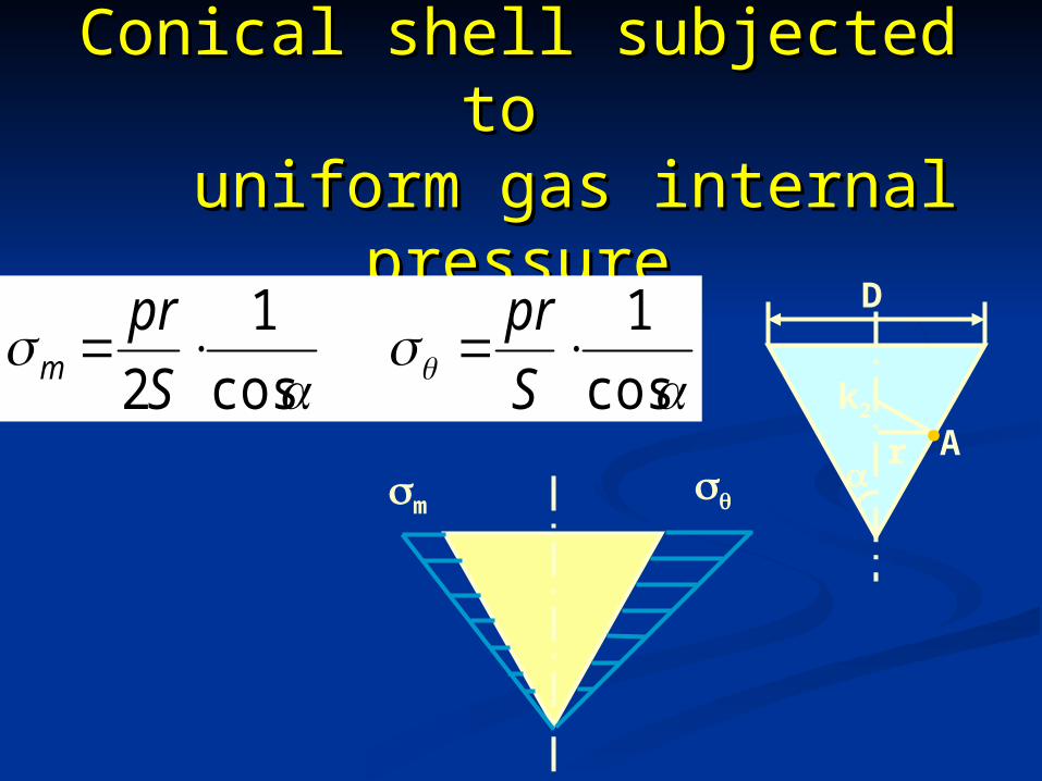
Conical shell subjected to Conical shell subjected to uniform gas internal uniform gas internal
pressurepressureD
r
.Ak2
cos
1
cos
1
2
S
pr
S
prm
m
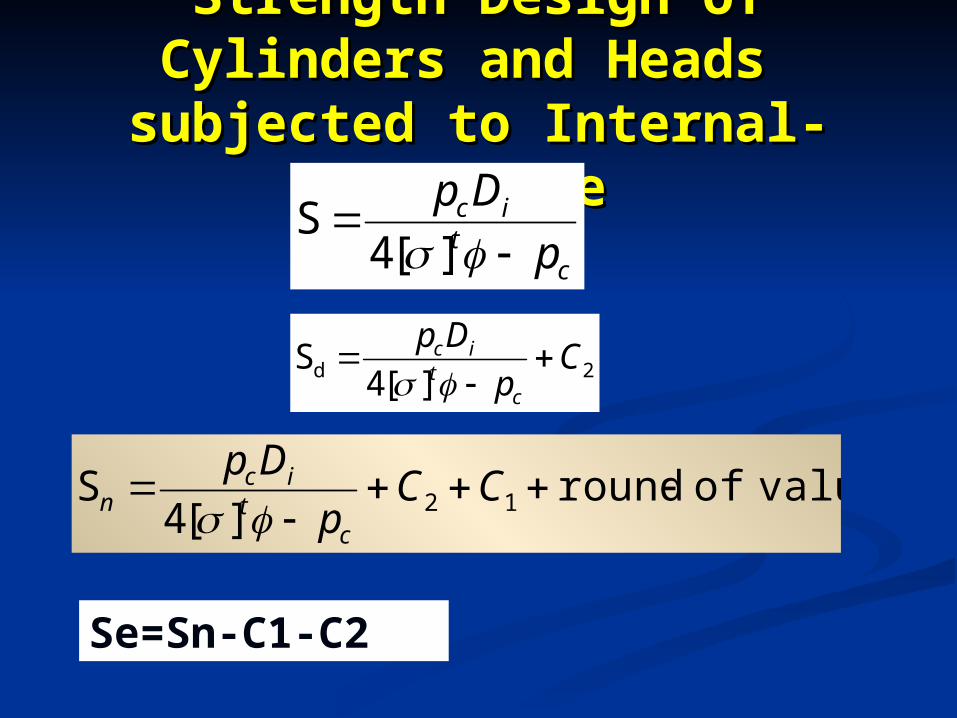
Strength Design of Strength Design of Cylinders and Heads Cylinders and Heads subjected to Internal-subjected to Internal-
PressurePressurec
tic
p
Dp
][4S
2d ][4S C
p
Dp
ct
ic
valueofround][4
S 12
CCp
Dp
ct
icn
Se=Sn-C1-C2
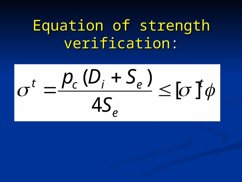
Equation of strength Equation of strength verificationverification::
t
e
eict
S
SDp][
4
)(
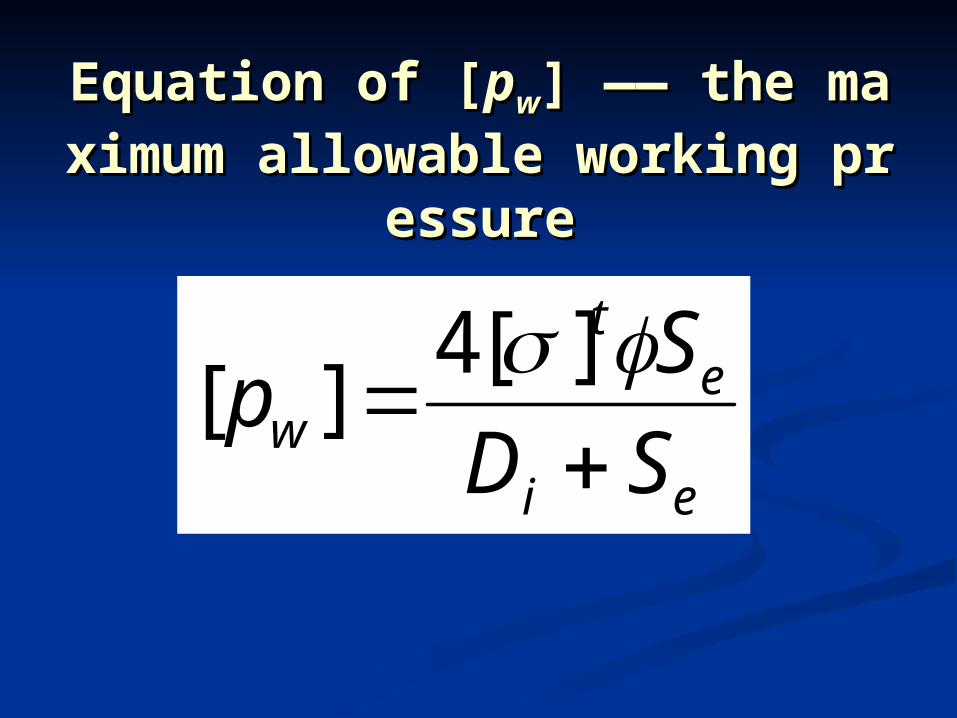
Equation of [Equation of [ppww] —— the maxi] —— the maximum allowable working pressmum allowable working press
ureure
ei
et
w SD
Sp
][4][
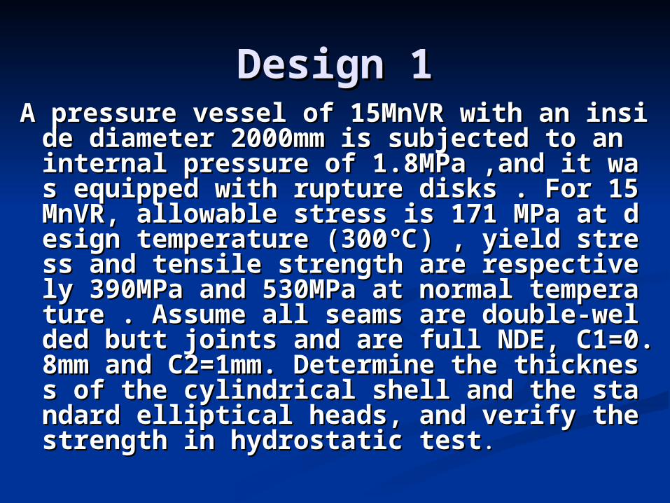
Design 1Design 1A pressure vessel of 15MnVR with an insidA pressure vessel of 15MnVR with an insid
e diameter 2000mm is subjected to an inte diameter 2000mm is subjected to an internal pressure of 1.8MPa ,and it was equiernal pressure of 1.8MPa ,and it was equipped with rupture disks . For 15MnVR, alpped with rupture disks . For 15MnVR, allowable stress is 171 MPa at design templowable stress is 171 MPa at design temperature (300℃) , yield stress and tensile serature (300℃) , yield stress and tensile strength are respectively 390MPa and 530trength are respectively 390MPa and 530MPa at normal temperature . Assume all MPa at normal temperature . Assume all seams are double-welded butt joints and seams are double-welded butt joints and are full NDE, C1=0.8mm and C2=1mm. Dare full NDE, C1=0.8mm and C2=1mm. Determine the thickness of the cylindrical etermine the thickness of the cylindrical shell and the standard elliptical heads, ashell and the standard elliptical heads, and verify the strength in hydrostatic testnd verify the strength in hydrostatic test . .
Design 2Design 2
Determine the maximum working prDetermine the maximum working pressure in a cylindrical shell subjecteessure in a cylindrical shell subjected to an internal working pressure. Led to an internal working pressure. Let DN = 1100mm, Sn =11mm, C=2mm , t DN = 1100mm, Sn =11mm, C=2mm , Φ=0.9 , [σ]t=147MPaΦ=0.9 , [σ]t=147MPa. .
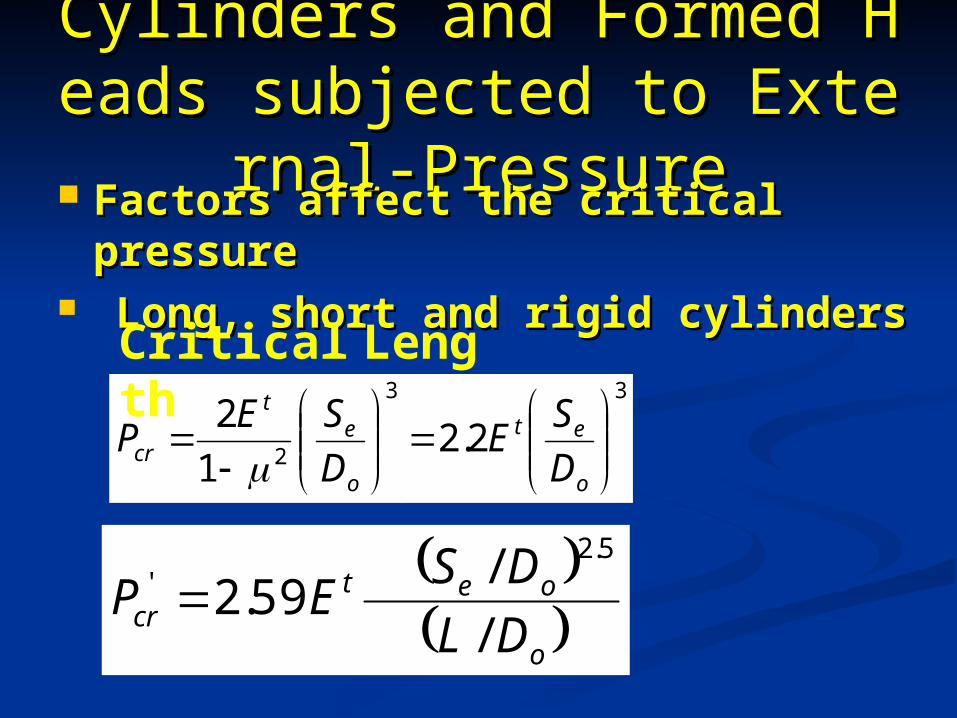
Cylinders and Formed HeadCylinders and Formed Heads subjected to External-Press subjected to External-Pres
suresure Factors affect the critical pressureFactors affect the critical pressure Long, short and rigid cylindersLong, short and rigid cylinders
3
21
2
o
et
cr D
SEP
3
2.2
o
et
D
SE
o
oetcr DL
DSEP
/
/ 59.2
5.2'
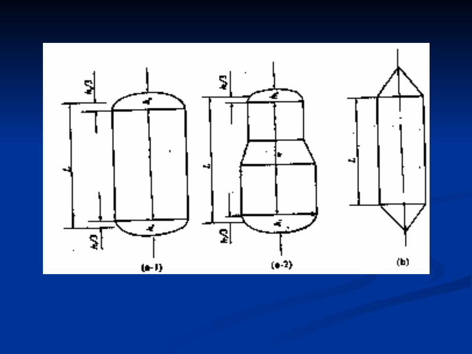
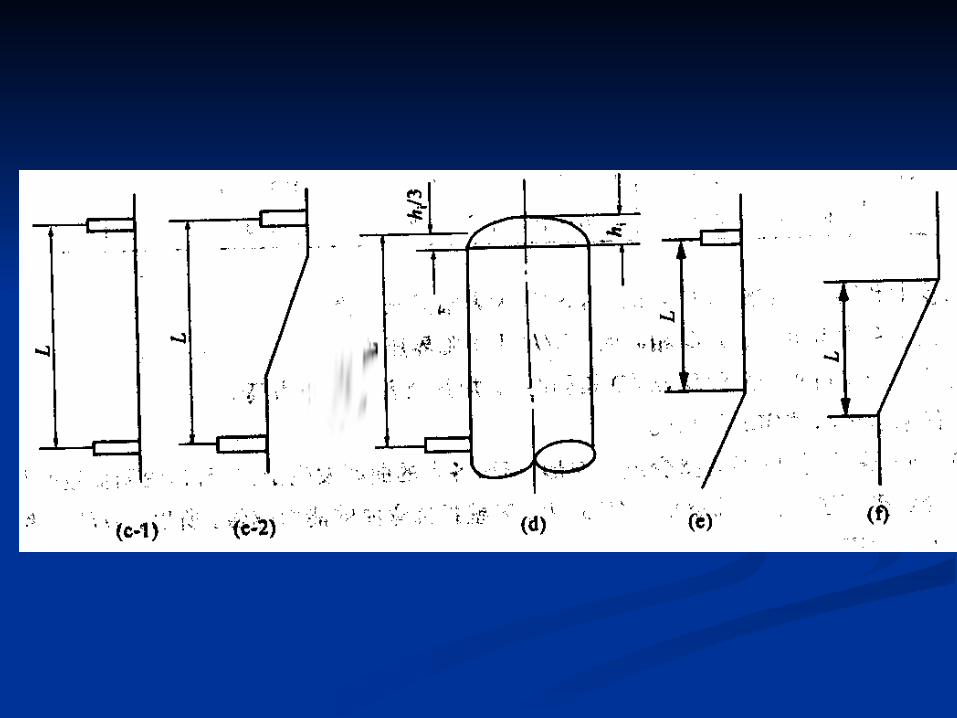
Critical Length
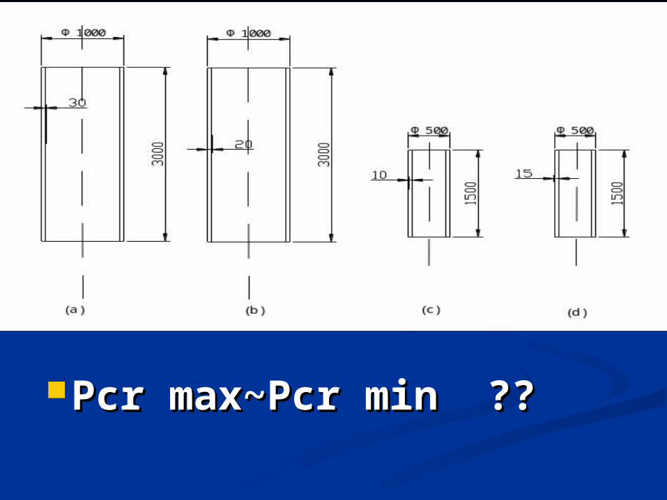
Pcr max~Pcr min Pcr max~Pcr min ????
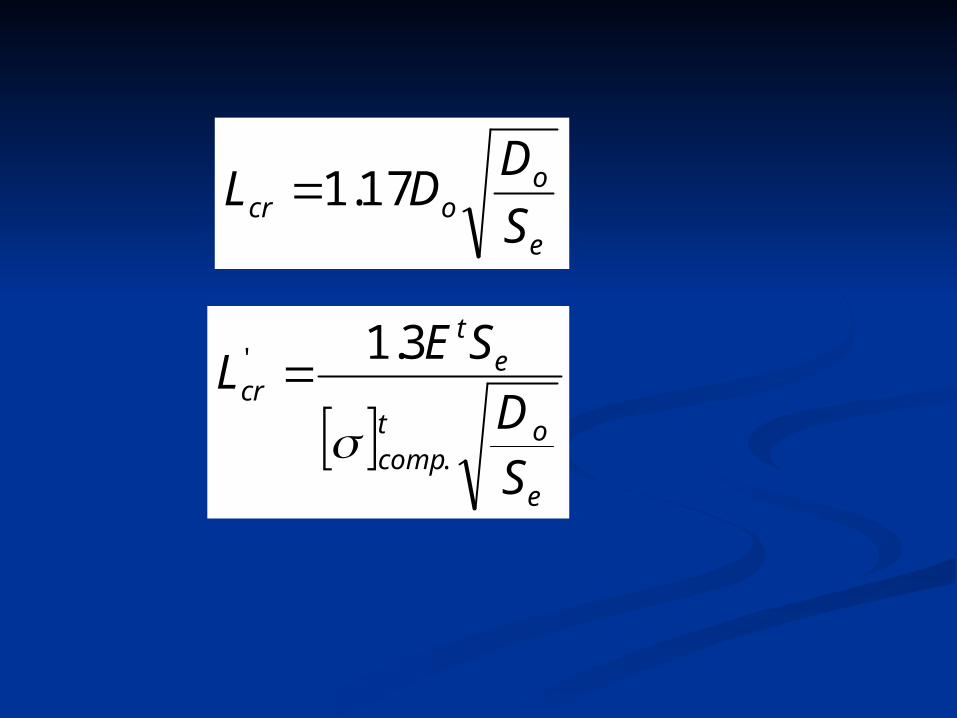
e
oocr S
DDL 17.1
e
otcomp
et
cr
SD
SEL
3.1
.
'
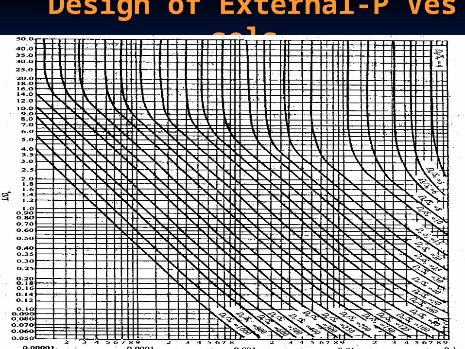
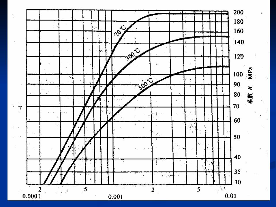
Design of External-P VesselsDesign of External-P Vessels
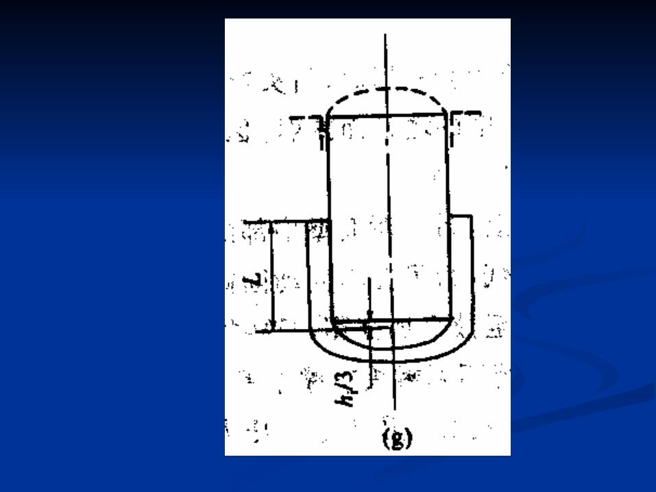
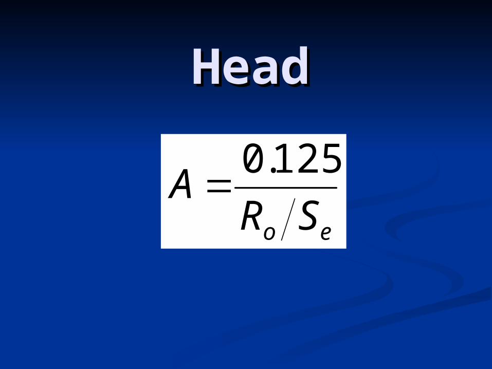
HeadHead
eo SRA
125.0
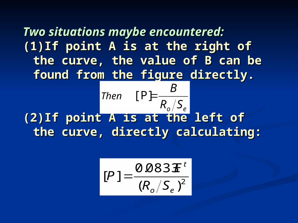
Two situations maybe Two situations maybe encountered:encountered:
(1)If point A is at the right of the (1)If point A is at the right of the curve, the value of B can be curve, the value of B can be found from the figure directly.found from the figure directly.
(2)If point A is at the left of the (2)If point A is at the left of the curve, directly calculating:curve, directly calculating:
eo SR
BThen [P]
2)(
0833.0][
eo
t
SR
EP
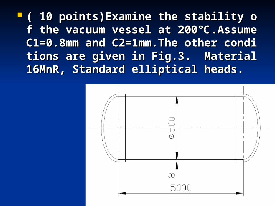
( 10 points)Examine the stability of t( 10 points)Examine the stability of the vacuum vessel at 200℃.Assume Che vacuum vessel at 200℃.Assume C1=0.8mm and C2=1mm.The other co1=0.8mm and C2=1mm.The other conditions are given in Fig.3. Material nditions are given in Fig.3. Material 16MnR, Standard elliptical heads.16MnR, Standard elliptical heads.
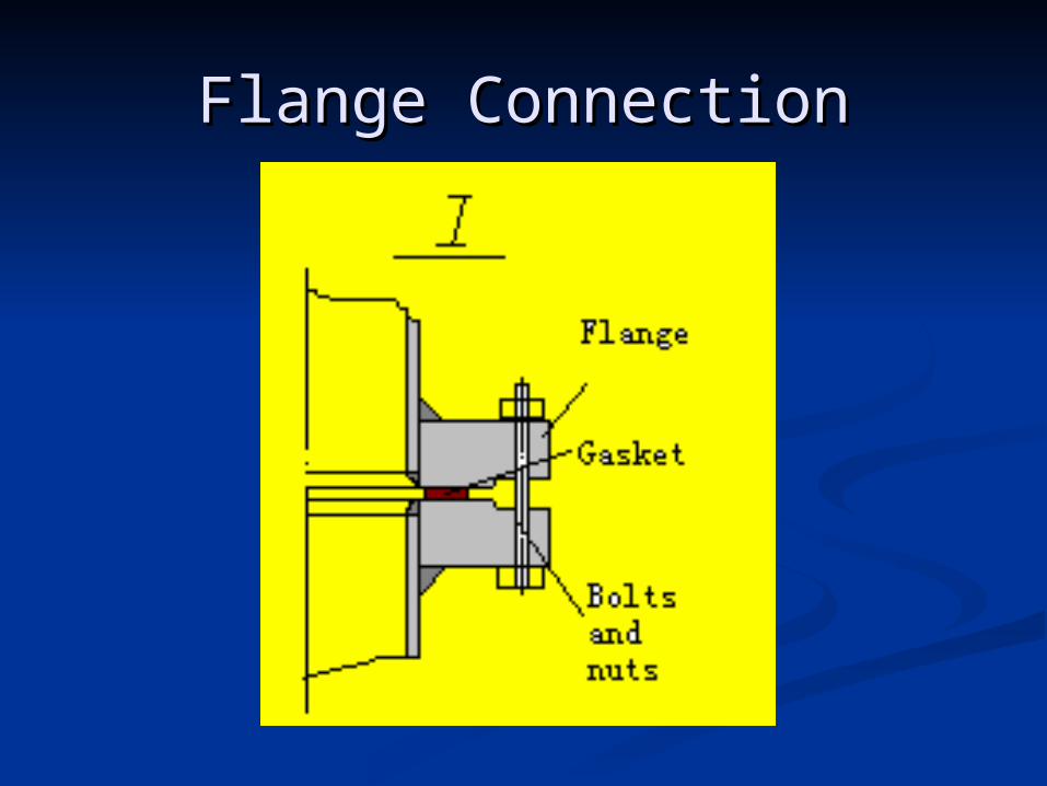
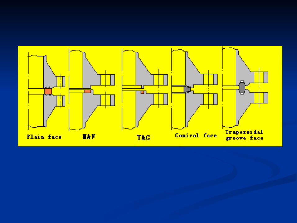
Flange ConnectionFlange Connection
Support for vesselsSupport for vessels PositonPositon Dangerous SectionDangerous Section
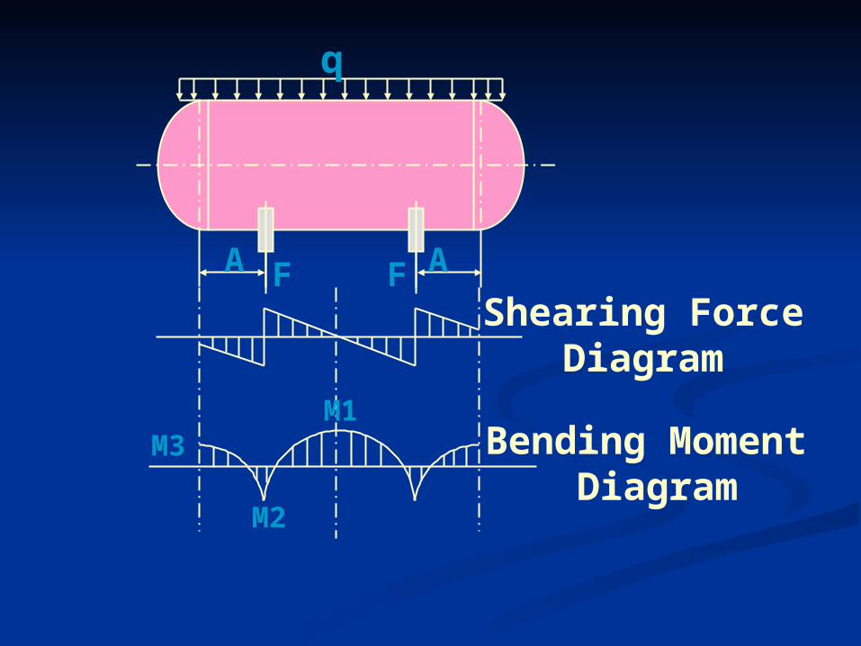
Shearing ForceDiagram
Bending Moment Diagram
M1
M2
M3
F FA A
q
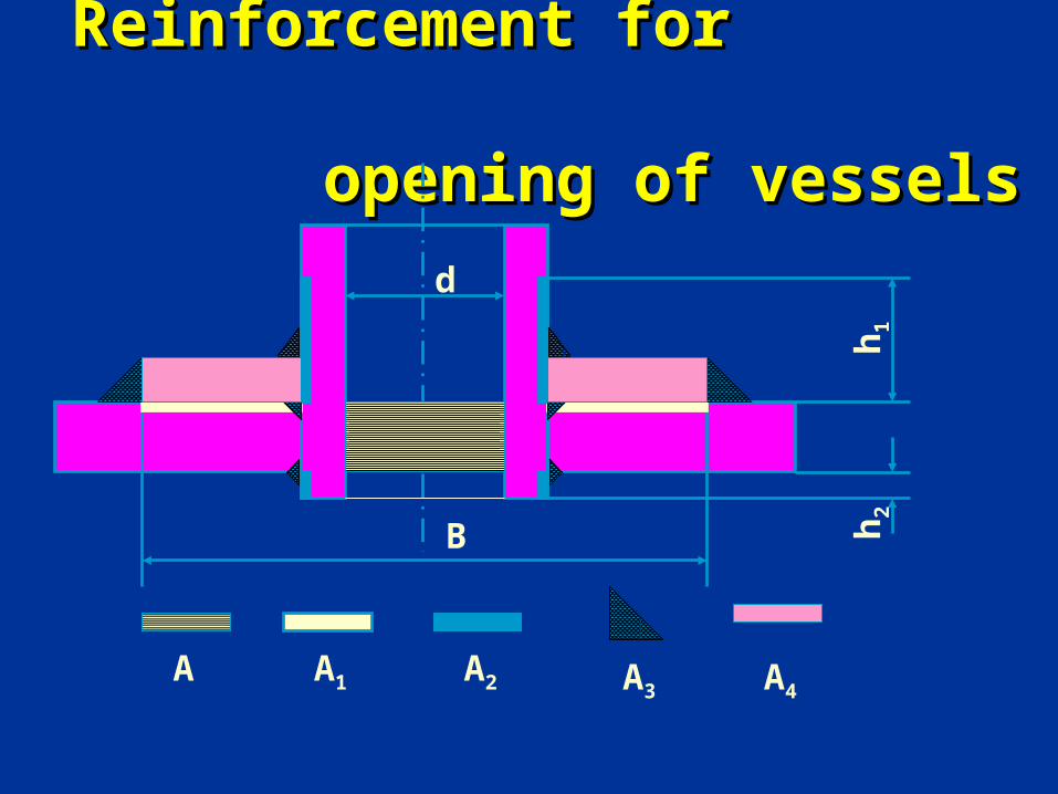
Reinforcement for Reinforcement for opening of vessels opening of vessels
A1 A3 A4A2A
B
h1
h2
d
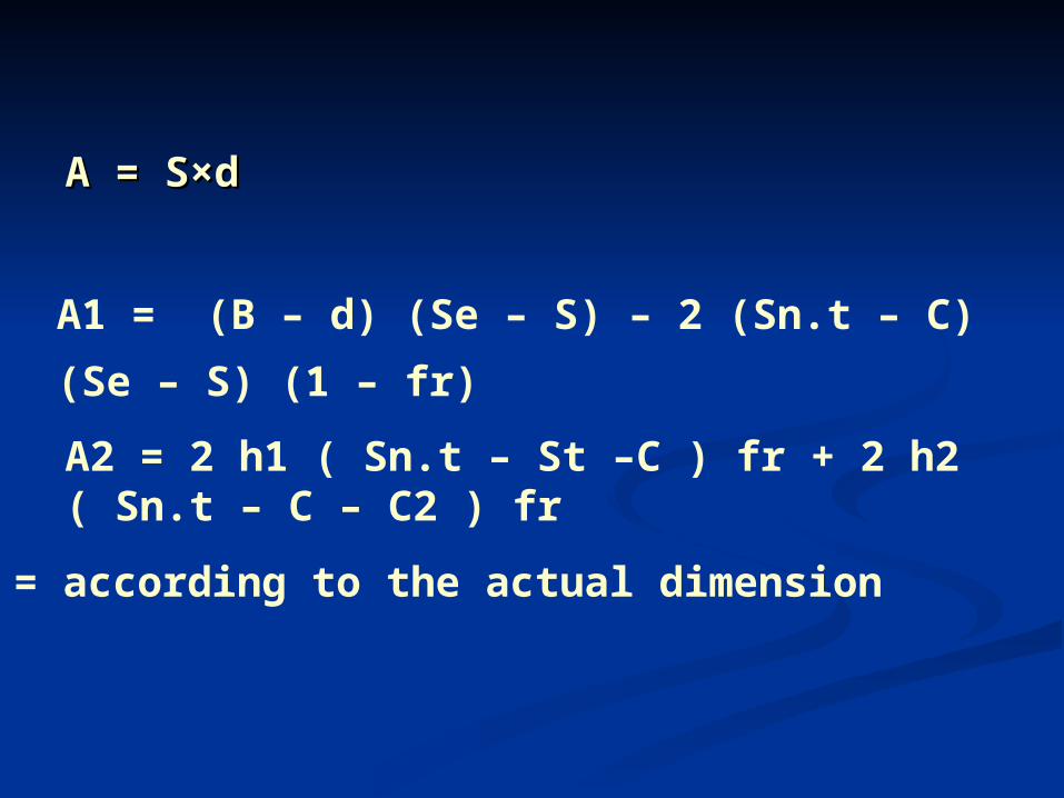
A = S×dA = S×d
A1 = (B – d) (Se – S) – 2 (Sn.t – C) (Se – S) (1 – fr)
A2 = 2 h1 ( Sn.t – St –C ) fr + 2 h2 ( Sn.t – C – C2 ) fr
A3 = according to the actual dimension
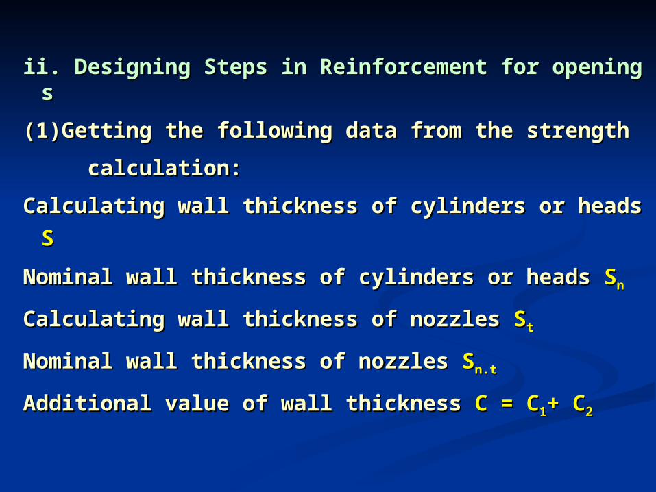
ii. Designing Steps in Reinforcement for openingsii. Designing Steps in Reinforcement for openings
(1)Getting the following data from the strength (1)Getting the following data from the strength
calculation:calculation:
Calculating wall thickness of cylinders or heads Calculating wall thickness of cylinders or heads SS
Nominal wall thickness of cylinders or heads Nominal wall thickness of cylinders or heads SSnn
Calculating wall thickness of nozzles Calculating wall thickness of nozzles SStt
Nominal wall thickness of nozzlesNominal wall thickness of nozzles SSn.tn.t
Additional value of wall thickness Additional value of wall thickness C = CC = C11+ C+ C22
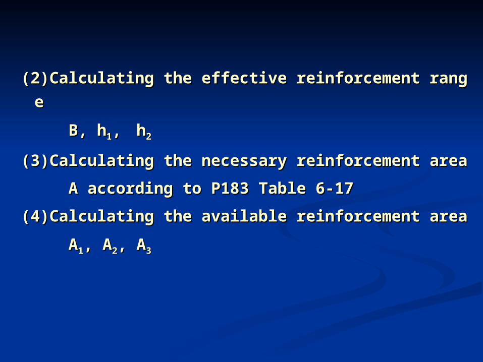
(2)Calculating the effective reinforcement range (2)Calculating the effective reinforcement range
B, hB, h11, , hh22
(3)Calculating the necessary reinforcement area (3)Calculating the necessary reinforcement area
A according to P183 Table 6-17A according to P183 Table 6-17
(4)Calculating the available reinforcement area (4)Calculating the available reinforcement area
AA11, A, A22, A, A33
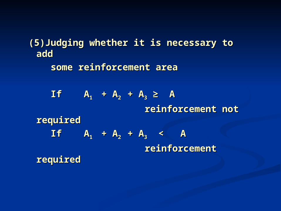
(5)Judging whether it is necessary to (5)Judging whether it is necessary to add add
some reinforcement areasome reinforcement area
If AIf A1 1 + A + A2 2 + A+ A33 ≥ A ≥ A
reinforcement not reinforcement not requiredrequired
If AIf A1 1 + A + A2 2 + A+ A33 < A < A
reinforcement requiredreinforcement required
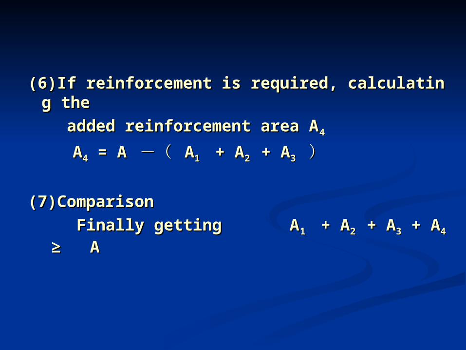
(6)If reinforcement is required, calculating t(6)If reinforcement is required, calculating the he
added reinforcement area Aadded reinforcement area A44
AA44 = A = A -( -( AA1 1 + A + A2 2 + A+ A33 ))
(7)Comparison(7)Comparison Finally getting AFinally getting A1 1 + A + A2 2 + A+ A33 + A + A44 ≥ A ≥ A