REV81-2E - Η εταιρία μας | Aνελκυστήρες Χατζηθεοχάρης · Web...
350
EUROPEAN STANDARD NORME EUROPÉENNE EUROPÄISCHE NORM EN 81-2 February 1998 ICS 91.140.90 Descriptors : lifts, goods lifts, definition, building codes, installation, safety requirements, lift cars, landing doors, lift wells, compensating ropes, shock absorbers, machine rooms, electrical installations, safety devices, stopping devices, locking devices, name plate, instructions, maintenance, conformity tests, certification English version Safety rules for the construction and installation of lifts – Part 2 : Hydraulic lifts Règles de sécurité pour la construction et l’installation des ascenseurs – Partie 2 : Ascenseurs hydrauliques Sicherheitsregeln für die Konstruktion und den Einbau von Aufzügen - Teil 2 : Hydraulische betriebene Personen-und Lastenaufzüge This European Standard was approved by CEN on (annéee-mois-jour). CEN members are bound to comply with the CEN/CENELEC internal Regulations which stipulate the conditions for giving this European Standard the status of a national standard without any alteration. Up-to-date lists and bibliograhical references concerning such national standards may be obtained on application to the Central Secretariat or to any CEN member. This European Standard exists in three official versions (English, French, German). A version in any other language made by translation under the responsibility of a CEN member into its own language and notified to the Central Secretariat has the same status as the official versions. CEN members are the national standard bodies of Austria, Belgium, Czech Republic, Denmark, Finland, France, Germany, Greece, Iceland, Ireland, Italy, Luxembourg, Netherlands, Norway, Portugal, Spain, Sweden, Switzerland and United Kingdom. Ref. No. EN 81-2:1998 E
Transcript of REV81-2E - Η εταιρία μας | Aνελκυστήρες Χατζηθεοχάρης · Web...

EUROPEAN STANDARD
NORME EUROPÉENNE
EUROPÄISCHE NORM
EN 81-2
February 1998
ICS 91.140.90
Descriptors : lifts, goods lifts, definition, building codes, installation, safety requirements, lift cars, landing doors, lift wells, compensating ropes, shock absorbers, machine rooms, electrical installations, safety devices, stopping devices, locking devices, name plate, instructions, maintenance, conformity tests, certification
English versionSafety rules for the construction and installation of lifts – Part 2 :
Hydraulic lifts
Règles de sécurité pour la construction et l’installation des ascenseurs – Partie 2 : Ascenseurs
hydrauliques
Sicherheitsregeln für die Konstruktion und den Einbau von Aufzügen - Teil 2 : Hydraulische
betriebene Personen-und Lastenaufzüge
This European Standard was approved by CEN on (annéee-mois-jour).
CEN members are bound to comply with the CEN/CENELEC internal Regulations which stipulate the conditions for giving this European Standard the status of a national standard without any alteration.
Up-to-date lists and bibliograhical references concerning such national standards may be obtained on application to the Central Secretariat or to any CEN member.
This European Standard exists in three official versions (English, French, German). A version in any other language made by translation under the responsibility of a CEN member into its own language and notified to the Central Secretariat has the same status as the official versions.
CEN members are the national standard bodies of Austria, Belgium, Czech Republic, Denmark, Finland, France, Germany, Greece, Iceland, Ireland, Italy, Luxembourg, Netherlands, Norway, Portugal, Spain, Sweden, Switzerland and United Kingdom.
CENEuropean Committee for Standardization
Comité Européen de NormalisationEuropäisches Komitee für Normung
Central Secretariat : rue de Stassart 36, B-1050 Brussels
© 1996 Copyright reserved to all CEN members.
Ref. No. EN 81-2:1998 E

Page 2EN 81-2:1998
Contents
Foreword...........................................................................................................................60 Introduction.........................................................................................................70.1 General.................................................................................................................70.2 Principles..............................................................................................................80.3 Assumptions.........................................................................................................9
1 Scope.................................................................................................................112 Normative references.......................................................................................123 Definitions.........................................................................................................144 Units and symbols............................................................................................184.1 Units...................................................................................................................184.2 Symbols..............................................................................................................18
5 Lift well..............................................................................................................185.1 General provisions..............................................................................................185.2 Well enclosure....................................................................................................195.3 Walls, floor and ceiling of the well......................................................................225.4 Construction of the walls of lift wells and landing doors facing a car entrance...245.5 Protection of any spaces located below the car or the balancing weight...........255.6 Protection in the well..........................................................................................255.7 Headroom and pit...............................................................................................265.8 Exclusive use of the lift well................................................................................285.9 Lighting of the well..............................................................................................285.10 Emergency release.............................................................................................29
6 Machine and pulley rooms..............................................................................296.1 General provisions..............................................................................................296.2 Access................................................................................................................306.3 Construction and equipment of machine rooms.................................................306.4 Construction and equipment of pulley rooms.....................................................33
7 Landing doors...................................................................................................347.1 General provisions..............................................................................................347.2 Strength of doors and their frames.....................................................................357.3 Height and width of entrances............................................................................367.4 Sills, guides, door suspension............................................................................367.5 Protection in relation to door operation..............................................................377.6 Local lighting and «car here» signal lights..........................................................397.7 Locking and closed landing door check.............................................................407.8 Closing of automatically operated doors............................................................43
8 Car and balancing weight................................................................................438.1 Height of car.......................................................................................................438.2 Available car area, rated load, number of passengers.......................................438.3 Walls, floor and roof of the car............................................................................468.4 Apron..................................................................................................................478.5 Car entrance.......................................................................................................478.6 Car doors............................................................................................................488.7 Protection during operation of doors..................................................................498.8 Reversal of closing movement...........................................................................518.9 Electrical device for proving the car doors closed..............................................51
Page 3EN 81-2:1998
8.10 Sliding doors with multiple, mechanically linked panels.....................................528.11 Opening the car door..........................................................................................528.12 Emergency trap doors and emergency doors....................................................538.13 Car roof...............................................................................................................548.14 Car header..........................................................................................................558.15 Equipment on top of the car...............................................................................558.16 Ventilation...........................................................................................................558.17 Lighting...............................................................................................................558.18 Balancing weight................................................................................................56
9 Suspension, precautions against free fall, descent with excessive speed and creeping of the car....................................................................................56
9.1 Suspension.........................................................................................................569.2 Pulley and rope diameter ratios, rope/chain terminations..................................579.3 Distribution of load between the ropes or the chains.........................................589.4 Protection for pulleys and sprockets...................................................................589.5 Precautions against free fall, descent with excessive speed and creeping of the
car.......................................................................................................................609.6 Precautions against free fall of the balancing weight.........................................629.8 Safety gear.........................................................................................................629.9 Clamping device.................................................................................................649.10 Tripping means for safety gears and clamping devices.....................................669.11 Pawl device........................................................................................................719.12 Electrical anti-creep system................................................................................72
10 Guide rails, buffers and final limit switch.......................................................7210.1 General provisions concerning guide rails..........................................................7210.2 Guiding of the car and balancing weight............................................................7410.3 Car buffers..........................................................................................................7510.4 Stroke of car buffers...........................................................................................7610.5 Final limit switch..................................................................................................78
11 Clearances between car and wall facing the car entrance, and between car, balancing weight or balancing weight............................................................79
11.1 General provision...............................................................................................7911.2 Clearances between car and wall facing the car entrance.................................7911.3 Clearances between car, balancing weight or balancing weight........................80
12 Lift machine......................................................................................................8012.1 General provisions..............................................................................................8012.2 Jack....................................................................................................................8112.3 Piping.................................................................................................................8512.4 Stopping the machine and checking its stopped condition.................................8612.5 Hydraulic control and safety devices..................................................................8612.6 Checking the pressure........................................................................................9012.7 Tank....................................................................................................................9012.8 Speed.................................................................................................................9112.9 Emergency operation.........................................................................................9112.10 Protection of the pulley(s) or sprocket(s) on the jack.........................................9212.11 Protection of machinery......................................................................................9212.12 Motor run time limiter..........................................................................................9212.13 Slack rope (or chain) safety device for indirect acting lifts..................................9312.14 Protection against overheating of the hydraulic fluid..........................................93
Page 4EN 81-2:1998
13 Electric installations and appliances..............................................................9313.1 General provisions..............................................................................................9313.2 Contactors, relay-contactors, components of safety circuits..............................9413.3 Protection of motors and other electrical equipment..........................................9513.4 Main switches.....................................................................................................9613.5 Electric wiring.....................................................................................................9713.6 Lighting and socket outlets.................................................................................99
14 Protection against electric faults ; controls ; priorities................................9914.1 Failure analysis and electric safety devices........................................................9914.2 Controls............................................................................................................105
15 Notices, markings and operating instructions.............................................11015.1 General provisions............................................................................................11015.2 Car....................................................................................................................11015.3 Car roof.............................................................................................................11215.4 Machine and pulley rooms................................................................................11215.5 Well...................................................................................................................11315.6 Overspeed governor.........................................................................................11315.7 Pit.....................................................................................................................11315.8 Buffers..............................................................................................................11315.9 Landing identification........................................................................................11315.10 Electrical identification......................................................................................11315.11 Unlocking key for landing doors.......................................................................11415.12 Alarm device.....................................................................................................11415.13 Locking devices................................................................................................11415.14 Safety gear.......................................................................................................11415.15 Emergency lowering valve................................................................................11415.16 Hand pump.......................................................................................................11415.17 Groups of lifts...................................................................................................11515.18 Tank..................................................................................................................11515.19 Rupture valve/one-way restrictor......................................................................115
16 Examinations - Tests - Register - Maintenance...........................................11516.1 Examinations and tests....................................................................................11516.2 Register............................................................................................................11616.3 Installer information..........................................................................................117
Annex A (normative) List of the electric safety devices........................................119Annex B (normative) Unlocking triangle..................................................................120Annex C (informative) Technical dossier.................................................................121C.1 Introduction.......................................................................................................121C.2 General.............................................................................................................121C.3 Technical details and plans..............................................................................121C.4 Electric schematic diagrams and hydraulic circuit diagram..............................123C.5 Verification of conformity..................................................................................123
Annex D (normative) Examinations and tests before putting into service...........124D.1 Examinations....................................................................................................124D.2 Tests and verifications......................................................................................124
Annex E (informative) Periodical examinations and tests, examinations and tests after an important modification or after an accident...................................130
E.1 Periodical examinations and tests....................................................................130E.2 Examinations and tests after an important modification or after an accident. . .130
Page 5EN 81-2:1998
Annex F (normative) Safety components - Tests procedures for verification of conformity.......................................................................................................132
F.0 Introduction.......................................................................................................132F.1 Landing door locking devices...........................................................................135F.2 Kept free...........................................................................................................140F.3 Safety gear.......................................................................................................140F.4 Overspeed governors.......................................................................................148F.5 Buffers..............................................................................................................151F.6 Safety circuits containing electronic components.............................................157F.7 Rupture valve/one-way restrictor......................................................................161
Annex G (informative) Proof of guide rails.............................Erreur! Signet non défini.G.1 General .......................................................................Erreur! Signet non défini.G.2 Loads and forces.........................................................Erreur! Signet non défini.G.4 Impact factors..............................................................Erreur! Signet non défini.G.5 Calculations.................................................................Erreur! Signet non défini.G.6 Permissible deflections................................................Erreur! Signet non défini.G.7 Examples of calculation method..................................Erreur! Signet non défini.Annex H (normative) Electronic components - Failure exclusionErreur! Signet non défini.
Annex J (normative) Pendulum shock tests..........................Erreur! Signet non défini.J.1 General........................................................................Erreur! Signet non défini.J.2 Test rig.........................................................................Erreur! Signet non défini.J.3 Panels..........................................................................Erreur! Signet non défini.J.4 Test procedure............................................................Erreur! Signet non défini.J.5 Interpretation of the results..........................................Erreur! Signet non défini.J.6 Test report...................................................................Erreur! Signet non défini.J.7 Exceptions from the tests............................................Erreur! Signet non défini.Annex K (normative) Calculations of rams, cylinders, rigid pipes and fittings....216K.1 Calculation against over pressure....................................................................216K.2 Calculations of the jacks against buckling........................................................218
Annex ZA (informative) Clauses of this standard addressing essential requirements or other provisions of EU Directives.....................................223
Page 6EN 81-2:1998
Foreword
This European Standard has been prepared by Technical Committee CEN/TC 10 ''Passenger, goods and service lifts'' the Secretariat of which is held by AFNOR.
This European Standard shall be given the status of a national standard, either by publication of an identical text or by endorsement, at the latest by (mois année), and conflicting national standards shall be withdrawn at the latest by (mois année).
This standard has been prepared under a mandate given to CEN by the European Commission (and the European Free Trade Association) and supports essential requirements of EU Directive(s).
For relationship with EU Directive(s), see informative annex ZA, which is an integral part of this standard.
This is the second edition of the standard. It is an amendment of the edition 1987 and shall be given the status of a harmonised standard. The amendment is mainly based on the following points :
- elimination of national deviations ;
- incorporation of essential health and safety requirements from the relevant EU Directives ;
- elimination of obvious errors ;
- incorporation of proposals resulting from interpretation requests dealing with the improvement relative to the progress in technology ;
- improvement of the references to other standards according to the progress in that field.
After the CEN Enquiry on prEN81-2:1994 the EU Directive on Lifts (95/16/EC) was adopted. The requirements resulting from the essential health and safety requirements of this Directive being not taken into consideration in the draft have been summarised in the Addendum prA1:1996 to prEN81-2:1994 and submitted to the members of CEN/TC 10 for approval. Having received the approval this Addendum has been incorporated into this standard taking into account the comments received from TC members.
This standard does not correspond in all points to the present internal rules of CEN regarding the format of safety standards. However, the format of this standard has been accepted by the interested parties and is therefore regarded as the better way of implementation of the essential health and safety requirements than a formalistic re-draft. This mainly because of the coming into force of the EU Directive 95/16/EC on 97-07-01.
With the next revision of the standard, being already intended, this shortcomings will be removed.
According to the CEN/CENELEC Internal Regulations, the national standards organizations of the following countries are bound to implement this European Standard : Austria, Belgium, Czech Republic, Denmark, Finland, France, Germany, Greece, Iceland, Ireland, Italy, Luxembourg, Netherlands, Norway, Portugal, Spain, Sweden, Switzerland and the United Kingdon .

Page 7EN 81-2:1998
0 Introduction
0.1 General
0.1.1 The object of this standard is to define safety rules related to passenger- and goods/passenger-lifts with a view to safeguarding persons and objects against the risk of accidents associated with the user-, maintenance- and emergency operation of lifts 1)
0.1.2 A study has been made of the various aspects of incidents possible with lifts in the following areas :
0.1.2.1Risks possible due to :
a) shearing ;
b) crushing ;
c) falling ;
d) impact ;
e) trapping ;
f) fire ;
g) electric shock ;
h) failure of material due to :
1) mechanical damage ;
2) wear ;
3) corrosion.
0.1.2.2 Persons to be safeguarded :
a) users ;
b) maintenance and inspection personnel ;
c) persons outside the lift well, the machine room and pulley room (if any).
1) Within CEN/TC 10 an interpretation committee has been established to answer questions about the spirit in which the experts have drafted the various clauses of this standard.The issued interpretations are available from National Standards Bodies.
Page 8EN 81-2:1998
0.1.2.3 Objects to be safeguarded :
a) loads in car ;
b) components of the lift installation ;
c) building in which the lift is installed.
0.2 Principles
In drawing up this standard the following have been used.
0.2.1 This standard does not repeat all the general technical rules applicable to every electrical, mechanical, or building construction including the protection of building elements against fire.
It has, however, seemed necessary to establish certain requirements of good construction, either because they are peculiar to lift manufacture or because in the case of lift utilization the requirements may be more stringent than elsewhere.
0.2.2 This standard does not only address the essential safety requirements of the Lift Directive, but additionally states minimum rules for the installation of lifts into buildings/constructions. There may be in some countries regulations for the construction of buildings etc. which cannot be ignored.
Typical clauses affected by this are those defining minimum values for the height of the machine and pulley rooms and for their access doors dimensions.
0.2.3 When the weight, size and/or shape of components prevent them from being moved by hand, they are :
a) either fitted with attachments for lifting gear, or
b) designed so that they can be fitted with such attachments (e.g. by means of threaded holes), or
c) shaped in such a way that standard lifting gear can easily be attached.
0.2.4 As far as possible the standard sets out only the requirements that materials and equipment have to meet in the interests of safe operation of lifts.

Page 9EN 81-2:1998
0.2.5 Negotiations have been made between the customer and the supplier about :
a) the intended use of the lift ;
b) environmental conditions ;
c) civil engineering problems ;
d) other aspects related to the place of installation.
0.3 Assumptions
Possible risks have been considered of each component that may be incorporated in a complete lift installation.
Rules have been drawn up accordingly.
0.3.1 Components are :
a) designed in accordance with usual engineering practice and calculation codes, taking into account all failure modes ;
b) of sound mechanical and electrical construction ;
c) made of materials with adequate strength and of suitable quality ;
d) be free of defects.
Harmful materials, such as asbestos are not used.
0.3.2 Components are kept in good repair and working order, so that the required dimensions remain fulfilled despite wear.
0.3.3 Components will be selected and installed so that foreseeable environmental influences and special working conditions do not affect the safe operation of the lift.
0.3.4 By design of the load bearing elements, a safe operation of the lift is assured for loads ranging from 0 % to 100 % of the rated load.
0.3.5 The requirements of this standard regarding electrical safety devices are such that the possibility of a failure of an electric safety device complying with all the requirements of the standard needs not to be taken into consideration.
0.3.6 Users have to be safeguarded against their own negligence and unwitting carelessness when using the lift in the intended way.

Page 10EN 81-2:1998
0.3.7 A user may, in certain cases, make one imprudent act. The possibility of two simultaneous acts of imprudence and/or the abuse of instructions for use is not considered.
0.3.8 If in the course of maintenance work a safety device, normally not accessible to the users, is deliberately neutralised, safe operation of the lift is no longer assured, but compensatory measures will be taken to ensure users safety in conformity with maintenance instructions.
It is assumed that maintenance personnel is instructed and works according to the instructions.
0.3.9 For horizontal forces, the following have been used :
a) static force : 300 N ;
b) force resulting from impact : 1000 N ;
reflecting the values that one person can exert.
0.3.10 With the exception of the items listed below, a mechanical device built according to good practice and the requirements of the standard will not deteriorate to a point of creating hazard without the possibility of detection.
The following mechanical failures are considered :
a) breakage of the suspension ;
b) breakage and slackening of all linkage by auxiliary ropes, chains and belts ;
c) rupture in the hydraulic system (jack excluded) ;
d) small leakage in the hydraulic system (jack included).
0.3.11 The possibility of the devices against free fall or descent with excessive speed not setting, should the car free fall from the lowest landing, before the car strikes the buffer(s) is considered acceptable.
0.3.12 Provided that none of the failure mentioned in 0.3.10 occurs the speed of the car in down direction with any load (up to the rated load) is assumed not to exceed the rated speed downwards by more than 8 %.
0.3.13 The organisation within the building, where the lift is installed, is such that it can respond effectively to emergency calls without undue delay (see 0.2.5).
0.3.14 Means of access are provided for the hoisting of heavy equipment (see 0.2.5).
Page 11EN 81-2:1998
0.3.15 To ensure the correct functioning of the equipment in the machine room, i.e. taking into account the heat dissipated by the equipment, the ambient temperature in the machine room is assumed to be maintained between + 5 °C and + 40 °C.
0.3.16 In the case of lifts provided with a restrictor/one-way restrictor as precaution against descent with excessive speed an impact speed of the car on the buffer (s) or the pawl device equal to rated speed downwards vd + 0,3 m/s shall be taken into account.
0.3.17 In the case of goods passenger lifts having a car whose available area in relationship to the rated load is greater than defined in table 1.1, a complete filling of the car with persons shall not create a dangerous situation.
1 Scope
1.1 This standard specifies the safety rules for the construction and installation of permanently installed new hydraulic lifts serving defined landing levels, having a car designed for the transportation of persons or persons and goods, suspended by jacks, ropes or chains and moving between guide rails inclined not more than 15° to the vertical.
1.2 In addition to the requirements of this standard supplementary requirements shall be considered in special cases (potentially explosive atmosphere, extreme climate conditions, seismic conditions, transporting dangerous goods, etc.).
1.3 This standard does not cover :
a) lifts with drives other than those stated in 1.1 ;
b) installation of hydraulic lifts in existing buildings 2) to the extent that space does not permit ;
c) important modifications (see annex E) to a lift installed before this standard is brought into application ;
d) lifting appliances, such as paternosters, mine lifts, theatrical lifts, appliances with automatic caging, skips, lifts and hoists for building and public works sites, ships' hoists, platforms for exploration or drilling at sea, construction and maintenance appliances ;
e) installations where the inclination of the guide rails to the vertical exceeds 15° ;
f) safety during transport, installation, repairs, and dismantling of lifts ;
g) hydraulic lifts with a rated speed exceeding 1 m/s.
However, this standard may usefully be taken as a basis.
Noise and vibrations are not dealt with in this standard because these are not relevant to the safe use of the lift.2) Existing building is a building which is used or was already used before the order for the lift was placed. A building whose internal structure is completely renewed is considered as a new building.

Page 12EN 81-2:1998
1.4 This standard does not specify the additional requirements necessary for the use of lifts in case of fire.
2 Normative references
This European standard incorporates by dated or undated reference, provisions from other publications. These normative references are cited at the appropriate places in the text and the publications are listed hereafter. For dated references, subsequent amendments to or revisions of any of these publications apply to this European standard only when incorporated in it by amendment or revision. For undated references the latest edition of the publication referred to applies.
CEN/CENELEC standards
EN 294 1992 Safety of machinery - Safety distances to prevent danger zones being reached by the upper limbs
EN 1050 Safety of machinery - Principles for risk assessment
EN 10025 Hot rolled products of non alloy structural steels - Technical delivery conditions
EN 50214 Flexible cables for lifts
EN 60068-2-6 Environmental testing - Part 2 : Tests - Test Fc : Vibration (sinusoidal)
EN 60068-2-27 Basic environmental testing procedures - Part 2 : Tests - Test Ea and guidance : Shock
EN 60068-2-29 Basic environmental testing procedures - Part 2 : Tests- Test Eb and guidance : Bump
EN 60249-2-2 Base materials for printed circuits - Part 2 : Specifications - Specification N° 2 : Phenolic cellulose paper copper-clad laminated sheet, economic quality
EN 60249-2-3 Base materials for printed circuits - Part 2 : Specifications - Specification N° 3 : Epoxyde cellule paper copper-clad laminated sheet of defined flammability (vertical burning test)
EN 60742 Isolating transformers and safety isolating transformers - Requirements
EN 60947-4-1 Low-voltage switchgear and controlgear - Part 4 : Contactors and motor-starters - Section 1 : Electromechanical contactors and motor-starters

Page 13EN 81-2:1998
EN 60947-5-1 Low-voltage switchgear and controlgear - Part 5 : Control circuit devices and switching elements - Section 1 : Electromechanical control circuit devices
EN 60950 Safety of information technology equipment, including electrical business equipment
EN 62326-1 Printed boards - Part 1 : Generic specification
EN 12015 1998 Electromagnetic compatibility - Product family standard for lifts, escalators and passenger conveyors - Emission
EN 12016 1998 Electromagnetic compatibility - Product family standard for lifts, escalators and passenger conveyors – Immunity
prEN 81-8 1997 Fire resistance tests of lift landing doors - Method of test and evaluation
IEC standards
IEC 60664-1 Insulation co-ordination for equipment within low-voltage systems - Part 1 : Principles, requirements and tests
IEC 60747-5 Semiconductor devices – Discrete devices and integrated circuits – Part 5 : Optoelectronic devices
CENELEC Harmonization Documents
HD 21.1 S3 Polyvinyl chloride insulated cables of rated voltages up to and including 450/750 V - Part 1 : General requirements
HD 21.3 S3 Polyvinyl chloride insulated cables of rated voltages up to and including 450/750 V - Part 3 : Non-sheathed cables for fixed wiring
HD 21.4 S2 Polyvinyl chloride insulated cables of rated voltages up to and including 450/750 V – Part 4 : Sheathed cables for fixed wiring
HD 21.5 S3 Polyvinyl chloride insulated cables of rated voltages up to and including 450/750 V - Part 5 : Flexible cables (cords)
HD 22.4 S3 Rubber insulated cables of rated voltages up to and including 450/750 V - Part 4 : Cords and flexible cables
HD 214 S2 Method for determining the comparative and the proof tracking indices of solid insulating materials under moist conditions
HD 323.2.14 S2 Basic environmental testing procedures - Part 2 : Tests - Test N : Change of temperature
HD 360 S2 Circular rubber insulated lift cables for normal use

Page 14EN 81-2:1998
HD 384.4.41 S2 Electrical installations of buildings - Part 4 : Protection for safety - Chapter 41 : Protection against electric shock
HD 384.5.54 S1 Electrical installations of buildings - Part 5 : Selection and erection of electrical equipment - Chapter 54 : Earthing arrangements and protective conductors
HD 384.6.61 S1 Electrical installations of buildings - Part 6 : Verification - Chapter 61 : Initial verification
ISO Standards
ISO 1219-1 1991 Fluid power systems and components – Graphic symbols and circuit diagram – Part 1 : Graphic symbols
ISO 6403 Hydraulic fluid power - Valves controlling flow and pressure - Test methods
ISO 7465 1997 Passager lifts and service lifts – Guide rails for lifts and counterweights – T type
3 Definitions
For the purposes of this standard, the following definitions apply :
apron (garde-pieds) (Schürze) : Smooth vertical part extending downwards from the sill of the landing or car entrance.
available car area (surface utile de la cabine) (Nutzfläche des Fahrkorbes) : Area of the car measured at a height of 1 m above floor level, disregarding handrails, which is available for passengers or goods during operation of the lift.
balancing weight (masse d’équilibrage) (Ausgleichgewicht) : Mass which saves energy by balancing all or part of the mass of the car.
buffer (amortisseur)(Puffer). A resilient stop at the end of travel, and comprising a means of braking using fluids or springs (or other similar means).
car (cabine) (Fahrkorb) : A part of the lift which carries the passengers and/or other loads.
clamping device (dispositif de blocage) (Klemmvorrichtung) : A mechanical device which when activated stops the car in downward motion and maintains it stationary at any point of the travel to limit the extent of creep.
Page 15EN 81-2:1998
direct acting lift (ascenseur à action directe) (direkt angetriebener Aufzug) : Hydraulic lift where the ram or cylinder is directly attached to the car or its sling.
down direction valve (soupape descente) (Abwärtsventil) : Electrically controlled valve in a hydraulic circuit for controlling the descent of the car.
electrical anti-creep system (système électrique anti-dérive) ( elektrisches Absinkkorrektursystem) : A combination of precautions against the danger of creeping.
electric safety chain (chaîne électrique des sécurités) (Elektrische Sicherheitskette) : The total of the electric safety devices connected in series.
full load pressure (pression à pleine charge) (Druck bei Vollast) : Static pressure exerted on the piping directly connected to the jack, the car with the rated load being at rest at the highest landing level.
goods passenger lift (ascenseur de charge) 1) (Lastenaufzug) : A lift mainly intended for the transport of goods, which are generally accompanied by persons.
guide rails (guides) (Führungsschienen) : The rigid components which provide guiding for the car or the balancing weight, if there is one.
headroom (partie supérieure de la gaine) (Schachtkopf) : Part of the well between the highest landing served by the car and the ceiling of the well.
hydraulic lift (ascenseur hydraulique) (hydraulischer Aufzug) : Lift in which the lifting power is derived from an electrically driven pump transmitting hydraulic fluid to a jack, acting directly or indirectly on the car (multiple motors, pumps and/or jacks may be used).
indirect acting lift (ascenseur à action indirecte) (indirekt angetriebener Aufzug) : A hydraulic lift where the ram or cylinder is connected to the car or the car sling by suspension means (ropes, chains).
instantaneous safety gear (parachute à prise instantanée) (Sperrfangvorrichtung) : A safety gear in which the full gripping action on the guide rails is almost immediate.
1) The French expression “ascenseur de charge” has been introduced into the French language document with the aim of harmonizing the texts in the three languages of CEN and of simplifying the wording. It does not in any way define a particular or supplementary category of lift.
Page 16EN 81-2:1998
instantaneous safety gear with buffered effect (parachute à prise instantanée avec effet amorti) (Sperrfangvorrichtung mit Dämpfung) : A safety gear in which the full gripping action on the guide rails is almost immediate, but the reaction on the car or balancing weight is limited by presence of an intermediate buffering system.
jack (vérin) (Heber) : A combination of a cylinder and a ram forming a hydraulic actuating the unit.
laminated glass (verre feuilleté) (Verbundsicherheitsglas VSG) : An assembly of 2 or more glass layers, each of which is bonded together using a plastic film.
levelling (nivelage) (Einfahren) : An operation which improves the accuracy of stopping at landings.
lift machine (machine) (Triebwerk) : The unit which drives and stops the lift, comprising the pump, pump motor and control valves.
machine room (local de machines) (Triebwerksraum) : A room in which machine or machines and/or the associated equipment are placed.
minimum breaking load of a rope (charge de rupture minimale d'un câble) (Mindestbruchkraft eines Seiles) : The product of the square of the nominal diameter of the rope (in square millimetres) and the nominal tensile strength of the wires (in newtons per square millimetre) and a coefficient appropriate to the type of rope construction.
non return valve (clapet de non retour) (Rückschlagventil) : A valve which allows flow in one direction only.
one-way restrictor (clapet freineur) (Drossel-Rückschlagventil) : A valve which allows free flow in one direction and restricted flow in the other direction.
overspeed governor (limiteur de vitesse) (Geschwindigkeitsbegrenzer) : A device which, when the lift attains a predetermined speed, causes the lift to stop, and if necessary causes the safety gear to be applied.
passenger (passager) (Fahrgast) : Any person transported by a lift in the car.
pawl device (dispositif à taquet) (Aufsetzvorrichtung) : A mechanical device for stopping involuntary descent of the car, and maintaining it stationary on fixed supports.
pit (cuvette) (Schachtgrube) : The part of the well situated below the lowest landing served by the car.
Page 17EN 81-2:1998
pressure relief valve (limiteur de pression) (Druckbegrenzungsventil) : A valve which limits the pressure to a pre-determined value by exhausting fluid.
progressive safety gear (parachute à prise amortie) (Bremsfangvorrichtung) : A safety gear in which retardation is effected by a braking action on the guide rails and for which special provisions are made so as to limit the forces on the car or balancing weight to a permissible value.
pulley room (local de poulies) (Rollenraum) : A room not containing the machine, in which pulleys are located, and in which the overspeed governor and the electrical equipment can also be housed.
rated load (charge nominale) (Nennlast) : The load for which the equipment has been built.
rated speed (vitesse nominale) (Nenngeschwindigkeit) : The speed v in metres per second of the car for which the equipment has been built :
vm = rated speed upwards in metres per second ;
vd = rated speed downwards in metres per second ;
vs = the higher value of both rated speeds vm and vd in metres per second .
re-levelling (isonivelage) (Nachstellen) : An operation, after the lift has stopped, to permit the stopping position to be corrected during loading or unloading, if necessary by successive movements (automatic or inching).
restrictor (réducteur de débit) (Drossel) : A valve in which the inlet and outlet are connected through a restricted passage way.
rupture valve (soupape de rupture) (Leitungsbruchventil) : A valve designed to close automatically when the pressure drop across the valve, caused by the increased flow in a pre-determined flow direction, exceeds a pre-set amount.
safety gear (parachute) (Fangvorrichtung) : A mechanical device for stopping, and maintaining stationary on the guide rails, the lift car or balancing weight in case of overspeeding in the downward direction or breaking of the suspension.
safety rope (câble de sécurité) (Sicherheitsseil) : An auxiliary rope attached to the car and the balancing weight for the purpose of tripping a safety gear in case of suspension failure.
“shut-off” valve (robinet d'isolement) (Absperrventil) : A manually operated two-way valve which can permit or prevent flow in either direction.

Page 18EN 81-2:1998
single acting jack (vérin à simple effet) (einfachwirkender Heber) : Jack in which displacement in one direction is by fluid action and in the other by influence of gravity.
sling (étrier) (Rahmen) : The metal framework carrying the car or balancing weight, connected to the means of suspension. This sling can be integral with the car enclosure.
travelling cable (câble pendentif)(Hängekabel) : Flexible cable between the car and a fixed point.
unlocking zone (zone de déverrouillage) (Entriegelungszone) : A zone, extending above and below the stopping level, in which the car floor must be to enable the corresponding landing door to be unlocked.
user (usager) (Benutzer) : Person making use of the services of a lift installation.
well (gaine) (Schacht) : The space in which the car and the balancing weight, if there is one, travels. This space is usually bounded by the bottom of the pit, the walls and the ceiling of the well.
4 Units and symbols
4.1 Units
The units used are chosen from the International System of units (SI).
4.2 Symbols
Symbols are explained relevant to the formulae used.
5 Lift well
5.1 General provisions
5.1.1 The requirements of this clause relate to wells containing one or more lift cars.
5.1.2 The balancing weight of a lift shall be in the same well as the car.
5.1.3 Jacks of a lift shall be in the same well as the car. They may extend into the ground or other spaces.
Page 19EN 81-2:1998
5.2 Well enclosure
5.2.1 A lift shall be separated from the surroundings by :
a) walls, floor and ceiling, or
b) sufficient space.
5.2.1.1 Totally enclosed well
In sections of the building where the well is required to contribute against the spread of fire, the well shall be totally enclosed by imperforate walls, floor and ceiling.
The only permissible openings are :
a) openings for landing doors ;
b) openings for inspection and emergency doors to the well and inspection traps ;
c) vent openings for escape of gases and smoke in the event of fire ;
d) ventilation openings ;
e) necessary openings for the functioning of the lift between the well and the machine or pulley rooms ;
f) openings in partition between lifts according to 5.6.
5.2.1.2 Partially enclosed well
Where the well is not required to contribute against the spread of fire, e.g. observation lifts in connection with galleries or atriums, tower buildings, etc., the well does not need to be totally enclosed, provided :
a) the height of the enclosure at places normally accessible to persons shall be sufficient to prevent such persons :
- being endangered by moving parts of the lift, and
- interfering with the safe operation of the lift by reaching lift equipment within the well either directly or with hand-held objects.
The height is assumed to be sufficient if it is in conformity with figure 1 and 2, that means :
1) minimum 3,50 m at a landing door side ;
2) minimum 2,50 m at other sides and with a minimum horizontal distance of 0,50 m to moving parts of the lift.
If the distance to moving parts exceeds 0,50 m, the value of 2,50 m can be reduced progressively to a minimum height of 1,10 m in a distance of 2,0 m ;

Page 20EN 81-2:1998
b) the enclosure shall be imperforate ;
c) the enclosure shall be located within 0,15 m maximum of the edges of floors, stairs or platforms (see figure 1) ;
d) provisions shall be taken to prevent the interference with the operation of the lift by other equipment (see 5.8 b) and 16.1.3 f)) ;
e) special precautions shall be taken for lifts exposed to weather (see 0.3.3), e.g. wall climbing lifts installed against the exterior walls of a building.
NOTE : Installation of lifts with partially enclosed well should only occur after full consideration of the environmental-/ location conditions.
C carH height of the enclosureD distance to moving parts of the lift (see figure 2)
Figure 1 : Partially enclosed well
Page 21EN 81-2:1998
Figure 2 : Partially enclosed well - Distances
5.2.2 Inspection and emergency doors - Inspection traps
5.2.2.1 Inspection and emergency doors, and inspection traps to the well, shall not be used except on grounds of safety to users or the requirements of maintenance.
5.2.2.1.1 Inspection doors shall have a minimum height of 1,40 m and a minimum width of 0,60 m.
Emergency doors shall have a minimum height of 1,80 m and a minimum width of 0,35 m.
Inspection traps shall have a maximum height of 0,50 m and a maximum width of 0,50 m.
Page 22EN 81-2:1998
5.2.2.1.2 When the distance between consecutive landing doorsills exceeds 11 m, intermediate emergency doors shall be provided, such that the distance between sills is not more than 11 m. This requirement is not called for in the case of adjacent cars, each fitted with an emergency door provision for which is made in 8.12.3.
5.2.2.2 Inspection and emergency doors and inspection traps shall not open towards the interior of the well.
5.2.2.2.1 The doors and traps shall be provided with a key-operated lock, capable of being reclosed and relocked without a key.
Inspection and emergency doors shall be capable of being opened from inside the well without a key even when locked.
5.2.2.2.2 Operation of the lift shall automatically depend on maintaining these doors and traps in the closed position. For this purpose electric safety devices in conformity with 14.1.2 shall be employed.
An electric safety device is not required in case of access door(s) to the pit (5.7.2.2) provided the door(s) does not give access to a hazardous zone. This is regarded to be the case if the free vertical distance between the lowest parts of car or balancing weight including guide shoes, apron, etc. during normal operation and the bottom of the pit is at least 2 m.
The presence of travelling cables, tensioning pulleys for the overspeed governor and similar installations is not regarded as being hazardous.
5.2.2.3 Inspection and emergency doors and inspection traps shall be imperforate, satisfy the same requirements for mechanical strength as the landing doors, and comply with the regulations relevant to the fire protection for the building concerned.
5.2.3 Ventilation of the well
The well shall be suitably ventilated. It shall not be used to provide ventilation of rooms other than those belonging to the lift.
NOTE : In the absence of relevant regulations or standards, it is recommended that ventilation openings at the top of the well, with a minimum area of 1 % of the horizontal section of the well, are provided.
5.3 Walls, floor and ceiling of the well
The structure of the well shall conform to National Building Regulations and be able to support at least the loads which may be applied by the machine, by the guide rails at the moment of safety gear operation, in the case of eccentric load in the car, by the action of the buffers, by loading and unloading the car, etc.
Page 23EN 81-2:1998
5.3.1 Strength of the walls
5.3.1.1 For the safe operation of the lift the walls shall have a mechanical strength such that when a force of 300 N, being evenly distributed over an area of 5 cm2 in round or square section, is applied at right angles to the wall at any point on either face they shall :
a) resist without permanent deformation ;
b) resist without elastic deformation greater than 15 mm.
5.3.1.2 Glass panels, plane or formed, placed at points normally accessible to persons shall be made of laminated glass up to a height as required in 5.2.1.2.
5.3.2 Strength of the pit floor
5.3.2.1 The floor of the pit shall be able to support beneath each guide rail except hanging guide rails :
force in newtons, due to the mass in kilogrammes of the guide rails plus the reaction in newtons at the moment of operation of the safety gear (see G.2.3 and G.2.4).
5.3.2.2 The floor of the pit shall be able to support beneath the car buffer supports 4 times the static load being imposed by the mass of the fully loaded car :
4 gn (P + Q)
where :
P = masses of the empty car and components supported by the car, i.e. part of the travelling cable, compensating ropes/chains (if any), etc. in kilogrammes ;
Q = rated load (mass) in kilogrammes ;
gn = standard acceleration of free fall, [9,81 (m/s2)].
5.3.2.3 The floor of the pit shall be able to support beneath the balancing weight travel area 4 times the static load being imposed by the mass of the balancing weight :
4 gn q P
where :
P = masses of the empty car and components supported by the car, i.e., part of the travelling cable, compensating ropes/chains (if any), etc. in kilogrammes ;
gn = standard acceleration of free fall, [9,81 (m/s2)] ;
q = balance factor (see G.2.4).

Page 24EN 81-2:1998
5.3.2.4 The floor of the pit shall be able to support beneath each jack the loads and forces (in newtons) imposed to it.
5.3.3 Strength of the ceiling
Not withstanding the requirements of 6.3.1 and/or 6.4.1, in the case of hanging guide rails the suspension points shall be able to take at least the loads and forces according to G.5.1.
5.3.4 Evaluation of the vertical forces during operation of pawl device
The total vertical force imposed on the fixed stops during operation of the pawl device can be evaluated approximately according to the following formulae :
a) pawl devices provided with energy accumulation type spring buffers, with or without buffered return movement :
b) pawl devices provided with energy dissipation type buffers :
where :
F = total vertical force in newtons on fixed stops imposed during operation of pawl device ;
P = the mass of the empty car and components supported by the car, i.e. part of the travelling cables, compensating ropes/chains (if any), etc. in kilogrammes ;
Q = rated load (mass) in kilogrammes ;
n = number of pawl devices.
5.4 Construction of the walls of lift wells and landing doors facing a car entrance
5.4.1 The following requirements relating to landing doors and walls, or parts of walls, facing a car entrance shall apply over the full height of the well.
For clearances between car and wall of the lift well facing the car entrance, see 11.
5.4.2 The assembly comprising the landing doors and any wall or part of a wall facing the car entrance shall form an imperforate surface over the full entrance width of the car, excluding the operational clearances of doors.

Page 25EN 81-2:1998
5.4.3 Below each landing door sill the wall of the lift well shall comply with the following requirements :
a) it shall form a vertical surface which is directly connected to the landing door sill, whose height is at least half the unlocking zone plus 50 mm and whose width is at least the clear opening of the car access plus 25 mm on both sides ;
b) this surface shall be continuous and be composed of smooth and hard elements, such as metal sheets, and shall be capable of withstanding a force of 300 N applied at a right angle to the wall at any point, being evenly distributed over an area of 5 cm2 in round or square section, it shall resist :
1) without permanent deformation ;
2) without elastic deformation greater than 10 mm ;
c) any projections shall not exceed 5 mm. Projections exceeding 2 mm shall be chamfered at least 75° to the horizontal ;
d) furthermore, it shall be either :
1) connected to the lintel of the next door, or
2) extended downwards using a hard smooth chamfer whose angle to the horizontal plane shall be at least 60°. The projection to this chamfer on the horizontal plane shall not be less than 20 mm.
5.5 Protection of any spaces located below the car or the balancing weight
If accessible spaces do exist below the car or balancing weight, the base of the pit shall be designed for an imposed load of at least 5000 N/m2, and :
a) either there shall be installed below the travelling area of the balancing weight a solid pier extending down to solid ground, or
b) the balancing weight shall be equipped with safety gear.
NOTE : Lift wells should preferably not be situated above a space accessible to persons.
5.6 Protection in the well
5.6.1 The travelling area of the balancing weight shall be guarded by means of a rigid screen extending from a position of not more than 0,30 m above the lift pit floor to a position at least 2,50 m.
The width shall be at least equal to that of the balancing weight plus 0,10 m on each side.
If this partition is perforate, EN 294, subclause 4.5.1 has to be respected.
Page 26EN 81-2:1998
5.6.2 Where the well contains several lifts there shall be a partition between the moving parts of different lifts.
If this partition is perforate, EN 294, subclause 4.5.1 has to be respected.
5.6.2.1 This partition shall extend at least from the lowest point of travel of the car or the balancing weight to a height of 2,50 m above the floor of the lowest landing. The width shall be as to prevent access from one pit to another, except where the conditions of 5.2.2.2.2 are met.
5.6.2.2 The partition shall extend through the full height of the well if the horizontal distance between the edge of the car roof and a moving part (car or balancing weight) of an adjacent lift is less than 0,50 m.
The width of the partition shall be at least equal to that of the moving part, or part of this, which is to be guarded, plus 0,10 m on each side.
5.7 Headroom and pit
5.7.1 Top clearances
5.7.1.1 When the ram is in its ultimate position, achieved through the means of ram stroke limitation according to 12.2.3, the following six conditions shall be satisfied at the same time :
a) the car guide rail lengths shall be such as would accommodate a further guided travel, expressed in metres, of at least 0,1 + 0,035 vm
2 2) ;
b) the free vertical distance between the level of the highest area on the car roof whose dimensions comply with 8.13.2 (areas on parts according to 5.7.1.1 c) excluded) and the level of the lowest part of the ceiling of the well (including beams and components located under the ceiling) situated in the projection of the car, expressed in metres, shall be at least 1,0 + 0,035 vm
2 ;
c) the free vertical distance, expressed in metres, between the lowest parts of the ceiling of the well and :
1) the highest pieces of equipment fixed on the roof of the car enclosure, except for those covered in 2) below, shall be at least 0,3 + 0,035 vm
2 ;
2) the highest part of the guide shoes or rollers, of the rope attachments and of the header or parts of vertically sliding doors, if any, shall be at least 0,1 + 0,035 vm
2 ;
2) 0,035 vm2 represents half the gravity stopping distance corresponding to 115 % of the rated speed :
1/2 = 0,0337 vm2 rounded to 0,035 vm
2.
Page 27EN 81-2:1998
d) there shall be above the car sufficient space to accommodate a rectangular block not less than 0,50 m x 0,60 m x 0,80 m resting on one of its faces. For lifts with direct roping, the suspension ropes and their attachments may be included in this space, provided that no rope centre-line shall be at a distance exceeding 0,15 m from at least one vertical surface of the block ;
e) the free vertical distance between the lowest parts of the ceiling of the well and the highest parts of an upward travelling ram-head assembly shall be at least 0,10 m ;
f) in the case of direct acting lifts, the value of 0,035 vm2 mentioned in a), b) and c) shall not be
taken into account.
5.7.1.2 When the car rests on its fully compressed buffers, the balancing weight guide rail lengths shall be such as would accommodate a further guided travel, expressed in metres, of at least 0,1 + 0,035 vd
2.
5.7.2 Pit
5.7.2.1 The lower part of the well shall consist of a pit, the bottom of which shall be smooth and approximately level, except for any buffer, jack and guide rail bases and water drainage devices.
After the building-in of guide rail fixings, buffers, any grids, etc., the pit shall be impervious to infiltration of water.
5.7.2.2 If there is an access door to the pit, other than the landing door, it shall comply with the requirements of 5.2.2.
Such a door shall be provided if the pit depth exceeds 2,50 m and if the layout of the building so permits.
If there is no other access a permanent means shall be provided inside the well, easily accessible from the landing door, to permit competent persons to descend safely to the floor of the pit. This shall not project into the clear running space of the lift equipment.
5.7.2.3 When the car rests on its fully compressed buffers, the following five conditions shall be satisfied at the same time :
a) there shall be in the pit sufficient space to accommodate a rectangular block not less than 0,50 m x 0,60 m x 1,0 m resting on one of its faces ;
b) the free vertical distance between the bottom of the pit and the lowest parts of the car, shall be at least 0,50 m. This distance may be reduced to a minimum of 0,10 m within a horizontal distance of 0,15 m between :
1) clamping device blocks, pawl devices, apron or parts of the vertical sliding door(s) and the adjacent wall(s) ;
2) the lowest parts of the car and the guide rails ;

Page 28EN 81-2:1998
c) the free vertical distance between the highest parts fixed in the pit, for instance jack supports, pipes and other fittings, and the lowest parts of the car, except for items detailed in b) 1) and b) 2) above, shall be at least 0,30 m ;
d) the free vertical distance between the bottom of the pit or the top of equipment installed there and the lowest parts of the downwards-travelling ram-head assembly of an inverted jack shall be at least 0,50 m.
However, if it is impossible to gain involuntary access under the ram head assembly (for example by providing screens in accordance with 5.6.1), this vertical distance may be reduced from 0,50 m to 0,10 m minimum ;
e) the free vertical distance between the bottom of the pit and the lowest guiding yoke of a telescopic jack below the car of a direct acting lift shall be at least 0,50 m.
5.7.2.4 With the car at its highest position determined by the fully compressed cushioned stop of the jack, the guide lengths of the balancing weight, if there is one, shall be such as would accommodate a further guided travel, expressed in metres, of at least 0,1 + 0,035 vm
2.
5.7.2.5 There shall be in the pit :
a) stopping device(s) accessible on opening the door(s) to the pit, and from the pit floor, in conformity with the requirements of 14.2.2 and 15.7 ;
b) a socket outlet (13.6.2) ;
c) means to switch the lift well lighting (5.9), accessible on opening the door(s) to the pit.
5.8 Exclusive use of the lift well
The well shall be exclusively used for the lift. It shall not contain cables or devices, etc., other than for the lift. The well may, however, contain heating equipment for the lift well excluding steam heating and high pressure water heating. However, any control and adjustment devices of the heating apparatus shall be located outside the well.
In the case of lifts according to 5.2.1.2, it is regarded as “well” in the case where enclosures :
a) are present : the area inside the enclosure ;
b) are missing : the area being inside a horizontal distance of 1,50 m from movable components of the lift (see 5.2.1.2).
5.9 Lighting of the well
The well shall be provided with permanently installed electric lighting, giving an intensity of illumination of at least 50 lux, 1 m above the car roof and the pit floor, even when all doors are closed.

Page 29EN 81-2:1998
This lighting shall comprise one lamp at most 0,50 m from the highest and lowest points in the well with intermediate lamps.
If use is made of the exception provided for in 5.2.1.2, this lighting may not be necessary if the electric lighting existing in the neighbourhood of the well is sufficient.
5.10 Emergency release
If there is a risk for persons working in the well being trapped and no means are provided to escape, either through the car, or through the well, alarm devices shall be installed at places where this risk exists.
The alarm devices shall fulfil the requirements of 14.2.3.2 and 14.2.3.3.
6 Machine and pulley rooms
6.1 General provisions
6.1.1 Lift machines, their associated equipment and pulleys, shall be in a special room, comprising solid walls, ceiling, floor, and door and/or trap, and shall be accessible only to authorized persons (maintenance, inspection and rescue).
Machine or pulley rooms shall not be used for purposes other than lifts. They shall not contain ducts, cables or devices other than for the lift.
These rooms may, however, contain :
a) machines for service lifts or escalators ;
b) equipment for air-conditioning or heating of these rooms, excluding steam heating and high pressure water heating ;
c) fire detectors or extinguishers, with a high operating temperature, appropriate for the electrical equipment, stable over a period of time, and suitably protected against accidental impact.
6.1.2 Diverter pulleys may be installed in the headroom of the well provided that they are located outside the projection of the car roof and that examinations and tests and maintenance operations can be carried out in complete safety from the car roof or from outside the well.
6.1.3 If the machine room is not adjacent to the well, the hydraulic piping and the electric wiring connecting the machine room with the lift well shall be installed in a duct or trough or in a section of a duct or trough, specially reserved for this purpose (see 12.3.1.2).

Page 30EN 81-2:1998
6.2 Access
6.2.1 Access to the interior of the machine and pulley rooms shall :
a) be capable of being properly lit by a permanent electric light fixture(s) ;
b) be easy to use in complete safety in all circumstances without necessitating entry into private premises.
6.2.2 A safe access for persons to machine and pulley rooms shall be provided. For preference this should be effected entirely by way of stairs. If it is not possible to install stairs, ladders satisfying the following requirements shall be used :
a) the access to the machine and pulley room shall not be situated more than 4 m above the level accessible by stairs ;
b) ladders shall be fastened to the access in such a way that they cannot be removed ;
c) ladders exceeding 1,50 m in height shall, when in position for access, form an angle between 65° and 75° to the horizontal and shall not be liable to slip or turn over ;
d) the clear width of the ladder shall be at least 0,35 m, the depth of the steps shall not be less than 25 mm and in the case of vertical ladders the distance between the steps and the wall behind the ladder shall not be less than 0,15 m ; the steps shall be designed for a load of 1500 N ;
e) adjacent to the top end of the ladder there shall be at least one hand hold within easy reach ;
f) around a ladder, within a horizontal distance of 1,50 m, the risk of falling by more than the height of the ladder shall be prevented.
6.3 Construction and equipment of machine rooms
6.3.1 Mechanical strength, floor surface
6.3.1.1 Machine rooms shall be so constructed to withstand the loads and forces to which they are intended to be subjected.
They shall be in durable material not favouring the creation of dust.
6.3.1.2 Room floors shall be of non-slip material, e.g. troweled concrete, corrugated iron.
6.3.2 Dimensions
6.3.2.1 The dimensions of machine rooms shall be sufficient to permit easy and safe working on equipments, especially the electrical equipment.
Page 31EN 81-2:1998
In particular there shall be provided at least a clear height of 2 m at working areas, and :
a) a clear horizontal area in front of the control panels and the cabinets. This area is defined as follows :
1) depth, measured from the external surface of the enclosures, at least 0,70 m ;
2) width, the greater of the following values : 0,50 m or the full width of the cabinet or panel ;
b) a clear horizontal area of at least 0,50 m x 0,60 m for maintenance and inspection of moving parts (if any) at points where this is necessary and, if need be, manual emergency operation (12.9).
6.3.2.2 The clear height for movement shall not be less than 1,80 m.
The access ways to the clear spaces mentioned in 6.3.2.1 shall have a width of at least 0,50 m. This value may be reduced to 0,40 m where there are no moving parts.
This full height for movement is taken to the underside of the structural roof beams and measured from both :
a) the floor of the access area ;
b) the floor of the working area.
6.3.2.3 There shall be a clear vertical distance of at least 0,30 m above the rotating parts of the machine.
6.3.2.4 When the machine room floor comprises a number of levels differing by more than 0,50 m, stairways or steps and guard rails shall be provided.
6.3.2.5 When the floor of the machine rooms has any recesses greater than 0,50 m deep and less than 0,50 m wide, or any ducts, they shall be covered.
6.3.3 Doors and trap doors
6.3.3.1 Access doors shall have a minimum width of 0,60 m and a minimum height of 1,80 m. They shall not open towards the inside of the room.
6.3.3.2 Access trap doors for persons shall give a clear passage of at least 0,80 m x 0,80 m, and shall be counterbalanced.
All trap doors, when they are closed, shall be able to support two persons, each counting for 1000 N on an area of 0,20 m x 0,20 m at any position, without permanent deformation.
Trap doors shall not open downwards, unless they are linked to retractable ladders. Hinges, if any, shall be of a type, which cannot be unhooked.

Page 32EN 81-2:1998
When a trap door is in the open position, precautions shall be taken to prevent the fall of persons (e.g. a guard rail).
6.3.3.3 The doors or trap doors shall be fitted with locks having keys, which can be opened without a key from inside the room.
Trap doors used only for access of material may be locked from the inside only.
6.3.4 Other openings
The dimension of holes in the slab and room floor shall be reduced to a minimum for their purpose.
With the aim of removing the danger of objects falling through openings situated above the well, including those for electric cables, ferrules shall be used, which project at least 50 mm above the slab or finished floor.
6.3.5 Ventilation
The machine rooms shall be suitably ventilated. Should the well be ventilated through the machine room, this has to be taken into account. Stale air from other parts of the building shall not be extracted directly into the machine room. It shall be such that the motors, and equipment, as well as electric cables, etc., are protected as far as it is reasonably practicable from dust, harmful fumes and humidity.
6.3.6 Lighting and socket outlets
The machine room shall be provided with permanently installed electric lighting on the basis of at least 200 lux at floor level. The supply for this lighting shall be in conformity with 13.6.1.
A switch placed inside close to the access point(s), at an appropriate height, shall control lighting of the room.
At least one socket outlet (13.6.2) shall be provided.
6.3.7 Handling of equipment
One or more metal supports or hooks with the indication of the safe working load (15.4.5), as appropriate, are provided in the machine room ceiling or on the beams, conveniently positioned to permit the hoisting of heavy equipment (see 0.2.5 and 0.3.14).
Page 33EN 81-2:1998
6.4 Construction and equipment of pulley rooms
6.4.1 Mechanical strength, floor surface
6.4.1.1 The pulley rooms shall be so constructed to withstand the loads and forces to which they will normally be subjected.
They shall be in durable material, not favouring the creation of dust.
6.4.1.2 The floors of the pulleys rooms shall be of non-slip material, e.g. troweled concrete, corrugated iron.
6.4.2 Dimensions
6.4.2.1 Pulley room dimensions shall be sufficient to provide easy and safe access for maintenance personnel to all the equipment.
The requirements of 6.3.2.1 b) and 6.3.2.2, sentence two and three, are applicable.
6.4.2.2 The height under the ceiling shall be at least 1,50 m.
6.4.2.2.1 There shall be a clear space of at least 0,30 m high above the pulleys.
6.4.2.2.2 If there are control panels and cabinets in the pulley room the provisions of 6.3.2.1 and 6.3.2.2 apply to this room.
6.4.3 Doors and trap doors
6.4.3.1 Access doors shall have a minimum width of 0,60 m and minimum height of 1,40 m. They shall not open towards the inside of the room.
6.4.3.2 Access trap doors for persons shall give a clear passage of at least 0,80 m x 0,80 m and shall be counterbalanced.
All trap doors, when they are closed, shall be able to support two persons, each counting for 1000 N on an area of 0,20 m x 0,20 m at any position, without permanent deformation.
Trap doors shall not open downwards, unless they are linked to retractable ladders. Hinges, if any, shall be of a type, which cannot be unhooked.
When a trap door is in the open position, precautions shall be taken to prevent the fall of persons (e.g. a guard rail).
6.4.3.3 Doors or trap doors shall be fitted with locks having a key, which can be opened without a key from inside the room.

Page 34EN 81-2:1998
6.4.4 Other openings
The dimensions of holes in the slab and pulley room floor shall be reduced to a minimum for their purpose.
With the aim of removing the danger of objects falling through openings situated over the well, including those for electric cables, ferrules shall be used which project at least 50 mm above the slab or finished floor.
6.4.5 Stopping device
A stopping device, in conformity with 14.2.2 and 15.4.4, shall be installed in the pulley room, close to the point(s) of access.
6.4.6 Temperature
If there is a risk of frost or condensation in the pulley rooms, precautions shall be taken to protect the equipment.
If the pulley rooms also contain electrical equipment, the ambient temperature shall be similar to that of the machine room.
6.4.7 Lighting and socket outlets
The pulley room shall be provided with permanently installed electric lighting, giving an intensity of an illumination of at least 100 lux at the pulley(s). The supply for this lighting shall be in conformity with 13.6.1.
A switch, placed inside, close to the access point, at an appropriate height, shall control the lighting of the room.
At least one socket outlet in conformity with 13.6.2 shall be provided. See also 6.4.2.2.2.
If there are control panels and cabinets in the pulley room, the provisions of 6.3.6 apply.
7 Landing doors
7.1 General provisions
The openings in the well giving access to the lift car shall be provided with imperforate landing doors.
When closed, the clearance between panels, or between panels and uprights, lintels or sills, shall be as small as possible.
Page 35EN 81-2:1998
This condition is considered to be fulfilled when the operational clearances do not exceed 6 mm. This value, due to wear, may reach 10 mm. These clearances are measured at the back of recesses, if present.
7.2 Strength of doors and their frames
7.2.1 Doors and their frames shall be constructed in such a way that they will not become deformed in the course of time. To this effect, it is recommended that they are made of metal.
7.2.2 Behaviour under fire conditions
Landing doors shall comply with the regulations relevant to the fire protection for the building concerned. PrEN 81-8 describes a method of the fire test.
7.2.3 Mechanical strength
7.2.3.1 Doors, with their locks, shall have a mechanical strength such that in the locked position and when a force of 300 N, being evenly distributed over an area of 5 cm2 in round or square section, is applied at right angles to the panel at any point on either face they shall :
a) resist without permanent deformation ;
b) resist without elastic deformation greater than 15 mm ;
c) during and after such a test the safety function of the door shall not be affected.
7.2.3.2 Under the application of a manual force (without a tool) of 150 N in the direction of the opening of the leading door panel(s) of horizontally sliding doors and folding doors, at the most unfavourable point, the clearances defined in 7.1 may exceed 6 mm, but they shall not exceed :
a) 30 mm for side opening doors ;
b) 45 mm in total for centre opening doors.
7.2.3.3 Door panels made of glass shall be fixed in such a way that forces demanded by this standard which may be applied are transferred without damaging the fixing of the glass.
Doors, with glass of dimensions greater than stated in 7.6.2, shall use laminated glass and, additionally withstand the pendulum shock tests, described in annex J.
After the tests the safety function of the door shall not be affected.
7.2.3.4 The fixing of the glass in doors shall ensure that the glass cannot slip out of the fixings, even when sinking.
Page 36EN 81-2:1998
7.2.3.5 The glass panels shall have markings giving the following information :
a) name of the supplier and trade mark ;
b) type of glass ;
c) thickness (e.g. 8/8/0,76 mm).
7.2.3.6 To avoid dragging of children hands, automatic power operated horizontally sliding doors made of glass of dimensions greater than stated in 7.6.2 shall be provided with means to minimise the risk, such as :
a) reducing the coefficient of friction between hands and glass ;
b) making the glass opaque up to a height of 1,10 m ;
c) sensing the presence of fingers, or
d) other equivalent methods.
7.3 Height and width of entrances
7.3.1 Height
Landing doors shall be such that a minimum clear height of the entrance is 2 m.
7.3.2 Width
The clear entrance of the landing doors shall not extend more than 50 mm in width beyond the clear car entrance on both sides.
7.4 Sills, guides, door suspension
7.4.1 Sills
Every landing entrance shall incorporate a sill of sufficient strength to withstand the passage of loads being introduced into the car.
NOTE : It is recommended that a slight counter slope be provided in front of each landing sill to avoid water from washing, sprinkling, etc., draining into the well.
7.4.2 Guides
7.4.2.1 Landing doors shall be designed to prevent, during normal operation, derailment, mechanical jamming, or displacement at the extremities of their travel.
Where the guides may become ineffective due to wear, corrosion or fire, emergency guidance shall be provided to maintain the landing doors in their position.
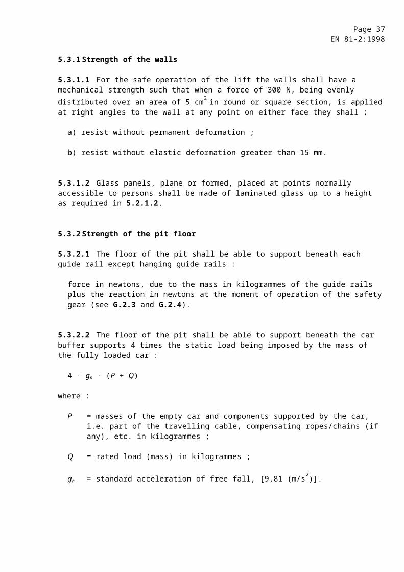
Page 37EN 81-2:1998
7.4.2.2 Horizontally sliding landing doors shall be guided top and bottom.
7.4.2.3 Vertically sliding landing doors shall be guided at both sides.
7.4.3 Suspension of vertically sliding doors
7.4.3.1 Panels of vertically sliding landing doors shall be fixed to two independent suspension elements.
7.4.3.2 Suspension ropes, chains, belts shall be designed with a safety factor of at least 8.
7.4.3.3 The diameter of suspension rope pulleys shall be at least 25 times the rope diameter.
7.4.3.4 Suspension ropes and chains shall be guarded against leaving the pulley grooves or sprockets.
7.5 Protection in relation to door operation
7.5.1 General
The doors and their surrounds shall be designed in such a way as to minimize risk of damage or injury due to jamming of a part of the person, clothing or other object.
To avoid the risk of shearing during operation, the exterior face of automatic power operated sliding doors shall not have recesses or projections exceeding 3 mm. Edges of these shall be chamfered in the opening direction of movement.
Exception to these requirements is made for the access to the unlocking triangle defined in annex B.
7.5.2 Power operated doors
Power operated doors shall be designed to reduce to a minimum the harmful consequences of a person being struck by a door panel.
To this effect, the following requirements shall be met :
7.5.2.1 Horizontally sliding doors
7.5.2.1.1 Automatic power operated doors
7.5.2.1.1.1 The effort needed to prevent the door closing shall not exceed 150 N. This measurement shall not be made in the first third of the travel of the door.
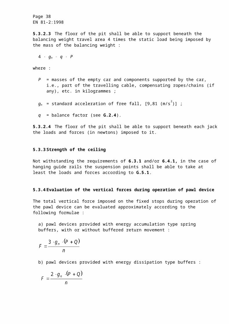
Page 38EN 81-2:1998
7.5.2.1.1.2 The kinetic energy of the landing door and the mechanical elements, which are rigidly connected to it, calculated or measured 5) at the average closing speed shall not exceed 10 J.
The average closing speed of a sliding door is calculated over its whole travel, less :
a) 25 mm at each end of the travel in the case of centrally closing doors ;
b) 50 mm at each end of the travel in the case of side closing doors.
7.5.2.1.1.3 A protective device shall automatically initiate re-opening of the door in the event of a person being struck, or about to be struck, by the door in crossing the entrance during the closing movement.
This protective device may be that for the car door (see 8.7.2.1.1.3).
The effect of the device may be neutralized during the last 50 mm of travel of each leading door panel.
In the case of a system, which makes the protective device inoperative after a predetermined time, to counteract persistent obstructions when closing the door, the kinetic energy defined in 7.5.2.1.1.2 shall not exceed 4 J during movement of the door with the protective device inoperative.
7.5.2.1.1.4 In the case of coupled car and landing doors operated simultaneously, the requirements of 7.5.2.1.1.1 and 7.5.2.1.1.2 are valid for the joined door mechanism.
7.5.2.1.1.5 The effort needed to prevent a folding door from opening shall not exceed 150 N. This measurement shall be made with the door collapsed such that the adjacent outer edges of the folded panels or equivalent, e.g. door frame, are at a distance of 100 mm.
7.5.2.1.2 Non-automatic power operated doors
When the closing of the door is carried out under the continuous control and supervision of the user, by continuous pressure on a button or similar (hold-to-run control), the average closing speed of the fastest panel shall be limited to 0,3 m/s, when the kinetic energy, calculated or measured as stated in 7.5.2.1.1.2, exceeds 10 J.
7.5.2.2 Vertically sliding doors
This type of sliding door shall only be used for goods passenger lifts.
5) Measured using, for example, a device consisting of a graduated piston acting on a spring with a spring constant of 25 N/mm, and fitted with an easy sliding ring allowing the extreme point of movement at the moment of impact to be measured. An easy calculation allows the graduation corresponding to the limits fixed to be determined.
Page 39EN 81-2:1998
Power closing shall only be used if the following four conditions are fulfilled at the same time :
a) the closing is carried out under the continuous control and supervision of the users ;
b) the average closing speed of the panels is limited to 0,3 m/s ;
c) the car door is of construction as provided for in 8.6.1 ;
d) the car door is at least two-thirds closed before the landing door begins to close.
7.5.2.3 Other types of doors
When using other types of doors, e.g. swing doors, with power operation, where there is a risk when opening or closing, of striking persons, precautions similar to those laid down for power operated sliding doors shall be taken.
7.6 Local lighting and «car here» signal lights
7.6.1 Local lighting
The natural or artificial lighting of the landings in the vicinity of landing doors shall be at least 50 lx at floor level, such that a user can see ahead when he is opening the landing door to enter the lift, even if the car light has failed (see 0.2.5).
7.6.2 «Car here» indication
In the case of landing doors with manual opening, the user needs to know, before opening the door, whether the car is there or not.
To this effect, there shall be installed, either :
a) one or more transparent vision panels conforming to the following four conditions at the same time :
1) mechanical strength as specified in 7.2.3.1, with the exception of the pendulum shock tests ;
2) minimum thickness of 6 mm ;
3) minimum glazed area per landing door of 0,015 m2 with a minimum of 0,01 m2 per vision panel ;
4) width of at least 60 mm, and at most 150 mm. The lower edge of vision panels which are wider than 80 mm shall be at least 1 m above floor level, or
b) an illuminated «car here» signal, which can only light up when the car is about to stop or has stopped at the particular landing. The signal shall remain illuminated whilst the car remains there.
Page 40EN 81-2:1998
7.7 Locking and closed landing door check
7.7.1 Protection against the risk of falling
It shall not be possible in normal operation to open a landing door (or any of the panels in the case of a multi-panel door) unless the car has stopped, or is on the point of stopping, in the unlocking zone of that door.
The unlocking zone shall not extend more than 0,20 m above and below the landing level.
In the case, however, of mechanically operated car and landing doors operating simultaneously, the unlocking zone may extend to a maximum of 0,35 m above and below the landing level.
7.7.2 Protection against shearing
7.7.2.1 With the exception of 7.7.2.2, it shall not be possible in normal operation to start the lift nor keep it in motion if a landing door, or any of the panels in the case of a multi-panel door is open. However, preliminary operations such as switching on the pump motor, for the movement of the car may take place.
7.7.2.2 Operation with doors open is permitted in the following zones :
a) in the unlocking zone to permit levelling, relevelling or electrical anti creeping at the corresponding floor level, provided the requirements of 14.2.1.2 are met ;
b) in a zone extending to a maximum height of 1,65 m above the landing level to permit the loading or unloading of the car, provided the requirements of 8.4.3, 8.14 and 14.2.1.4 are met, and :
1) the clear height between the landing door header and the floor of the car, in any position, shall not be less than 2 m, and
2) whatever the position of the car inside this zone, it must be possible, without special operation, to effect the complete closure of the landing door.
7.7.3 Locking and emergency unlocking
Each landing door shall be provided with a locking device satisfying the conditions of 7.7.1. This device shall be protected against deliberate misuse.
7.7.3.1 Locking
The effective locking of the landing door in the closed position shall precede the movement of the car. However, preliminary operations for the movement of the car may take place. The locking must be proved by an electric safety device in conformity with 14.1.2.
7.7.3.1.1 The car shall not be able to start until the locking elements are engaged by at least 7 mm ; see figure 3.
Page 41EN 81-2:1998
Figure 3 : Examples of locking elements
7.7.3.1.2 The element of the electric safety device proving the locked condition of the door panel(s) shall be positively operated without any intermediate mechanism by the locking element. It shall be foolproof but adjustable if necessary.
Specific case : In the case of locking devices used in installations requiring special protection against risks of humidity or explosion the connection may be only positive, provided the link between the mechanical lock and the element of the electric safety device proving the locked condition, can only be interrupted by destroying deliberately the locking device.
7.7.3.1.3 For hinged doors, locking shall be effected as near as possible to the vertical closing edge(s) of the doors, and maintained even in the case of panels sagging.
7.7.3.1.4 The locking elements and their fixings shall be resistant to shock, and be made or reinforced with metal.
7.7.3.1.5 The engagement of the locking elements shall be achieved in such a way that a force of 300 N in the opening direction of the door does not diminish the effectiveness of locking.
7.7.3.1.6 The lock shall resist, without permanent deformation during the test laid down in F.1, a minimum force at the level of the lock and in the direction of opening of the door of :
a) 1000 N in the case of sliding doors ;
b) 3000 N on the locking pin, in the case of hinged doors.
7.7.3.1.7 The locking action shall be effected and maintained by the action of gravity, permanent magnets, or springs. The springs shall act by compression, be guided and of such dimensions that, at the moment of unlocking, the coils are not compressed solid.
In the event of the permanent magnet (or spring) no longer fulfilling its function, gravity shall not cause unlocking.
Page 42EN 81-2:1998
If the locking element is maintained in position by the action of a permanent magnet, it shall not be possible to neutralize its effect by simple means (e.g. heat or shock).
7.7.3.1.8 The locking device shall be protected against the risk of an accumulation of dust, which could hinder its proper functioning.
7.7.3.1.9 Inspection of the working parts shall be easy, as, for example, by use of a vision panel.
7.7.3.1.10 In the case where the lock contacts are in a box, the fixing screws for the cover shall be of the captive type, so that they remain in the holes in the cover or box when opening the cover.
7.7.3.2 Emergency unlocking
Each of the landing doors shall be capable of being unlocked from the outside with the aid of a key, which will fit the unlocking triangle as defined in annex B.
Keys of this type shall be given only to a responsible person. They shall be accompanied by a written instruction detailing the essential precautions to be taken in order to avoid accidents which could result from an unlocking which was not followed by effective relocking.
After an emergency unlocking, the locking device shall not be able to remain in the unlocked position with the landing door closed.
In the case of landing doors driven by the car door, a device (either weight or springs) shall ensure the automatic closing of the landing door if this door becomes open, for whatever reason, when the car is outside the unlocking zone.
7.7.3.3 The locking device is regarded as a safety component and shall be verified according to the requirements in F.1.
7.7.4 Electrical device for proving the landing door closed
7.7.4.1 Each landing door shall be provided with an electric safety device in conformity with 14.1.2 for proving the closed position, so that the conditions imposed by 7.7.2 are satisfied.
7.7.4.2 In the case of horizontally sliding landing doors, coupled with car doors, this device may be in common with the device for proving the locked condition, provided that it is dependent upon the effective closing of the landing door.
7.7.4.3 In the case of hinged landing doors, this device shall be placed adjacent to the closing edge of the door or on the mechanical device proving the closed condition of the door.
Page 43EN 81-2:1998
7.7.5 Requirements common to devices for proving the locked condition and the closed condition of the door
7.7.5.1 It shall not be possible, from positions normally accessible to persons, to operate the lift with a landing door open or unlocked, after one single action not forming part of the normal operating sequence.
7.7.5.2 The means used to prove the position of a locking element shall have positive operation.
7.7.6 Sliding doors with multiple, mechanically linked panels
7.7.6.1 If a sliding door comprises several directly mechanically linked panels, it is permitted :
a) to place the device required in 7.7.4.1 or 7.7.4.2, on a single panel, and
b) to lock only one panel, provided that this single locking prevents the opening of the other panel(s) by hooking the panels in the closed position in case of telescopic doors.
7.7.6.2 If a sliding door comprises several indirectly, mechanically linked panels (e.g. by rope, belt or chain), it is permitted to lock only one panel provided that this single locking will prevent the opening of other panels, and that these are not fitted with a handle.
The closed position of the other panel(s), not locked by the locking device, shall be proved by an electric safety device in conformity with 14.1.2.
7.8 Closing of automatically operated doors
In normal operation, automatically operated landing doors shall be closed after the necessary period of time, which may be defined according to the traffic using the lift, in the absence of a command for the movement of the car.
8 Car and balancing weight
8.1 Height of car
8.1.1 The interior clear height of the car shall be at least 2 m.
8.1.2 The clear height of the car entrance(s) for the normal access of users shall be at least 2 m.
8.2 Available car area, rated load, number of passengers
8.2.1 General case
To prevent an overloading of the car by persons, the available area of the car shall be limited. To this effect the relationship between rated load and maximum available area is given in table 1.1.
Page 44EN 81-2:1998
Recesses and extensions, even of height less than 1 m, whether protected or not by separating doors, are only permitted if their area is taken into account in the calculation of maximum available car area.
Any available area in the entrance, when the doors are closed, shall also be taken into account.
Furthermore, overloading of the car shall be monitored by means of a device according to 14.2.5.
Table 1.1
Rated load,mass
kg
Maximum available car
area
m2
Rated load,mass
kg
Maximum available car
area
m2
100 1) 180 2) 225300375400450525600630675750800825
0,370,580,700,901,101,171,301,451,601,661,751,902,002,05
900 975100010501125120012501275135014251500160020002500 3)
2,202,352,402,502,652,802,902,953,103,253,403,564,205,00
1) Minimum for 1 person lift.
2) Minimum for 2 persons lift.
3) Beyond 2500 kg add 0,16 m2 for each extra 100 kg.
For intermediate loads the area is determined by linear interpolation.
8.2.2 Goods passenger lifts
8.2.2.1 For goods passenger lifts, hydraulically driven, the available area of the car may be greater than the value determined from table 1.1, but shall not exceed the value determined from table 1.1.A for the corresponding rated load.
Page 45EN 81-2:1998
Table 1.1.A
Rated load,mass
kg
Maximum availablecar area
(see 8.2.1)
m2
Rated load,mass
kg
Maximum availablecar area
(see 8.2.1)
m2
400450525600630675750800825900
1,681,842,082,322,422,562,802,963,043,28
9751000105011251200125012751350142515001600
3,523,603,723,904,084,204,264,444,624,805,04
Beyond 1600 kg, add 0,40 m2 for each 100 kg extra.
For intermediate loads, the area is determined by linear interpolation.
8.2.2.2 Nevertheless the available car area of a lift with balancing weight shall be such that a load in the car resulting from table 1.1 (8.2.1) shall not cause a pressure exceeding from 1,4 times the pressure the jack and the piping are designed for.
8.2.2.3 The design of the car, the car sling, the connection between the car and the ram (cylinder), the suspension means (of indirect acting lifts), the car safety gear, the rupture valve, the restrictor/one-way restrictor, the clamping device, the pawl device, the guide rails and the buffers shall be based on a load resulting from table 1.1 (8.2.1).
8.2.2.4 The requirements of 8.2.1 shall be applied and, in addition, design calculations shall take into account not only the load carried but also the weight of handling devices, which may enter the car.
8.2.3 Number of passengers
The number of passengers shall be obtained from :
a) either, the formula, , and the result rounded down to the nearest whole number,
or
b) table 1.2 whichever gives the smaller value.
Page 46EN 81-2:1998
Table 1.2
Number of passengers
Minimum available car
area
m2
Number of passengers
Minimum available car
area
m2
123456789
10
0,280,490,600,790,981,171,311,451,591,73
11121314151617181920
1,872,012,152,292,432,572,712,852,993,13
Beyond 20 passengers add 0,115 m2 for each extra passenger.
8.3 Walls, floor and roof of the car
8.3.1 The car shall be completely enclosed by walls, floor and roof, the only permissible openings being as follows :
a) entrances for the normal access of users ;
b) emergency trap doors and doors ;
c) ventilation apertures.
8.3.2 The walls, floor and roof shall have sufficient mechanical strength. The assembly comprising the sling, guide shoes, walls, floor and roof of the car shall have sufficient mechanical strength to resist the forces which will be applied in normal lift operation, in operation of the safety gear, the rupture valve, the clamping devices or the pawl devices, or impact of the car on its buffers.
8.3.2.1 Each wall of the car shall have a mechanical strength such that when a force of 300 N, being evenly distributed over an area of 5 cm2 in round or square section, is applied at right angles to the wall at any point from the inside of the car towards the outside, it shall :
a) resist without any permanent deformation ;
b) resist without elastic deformation greater than 15 mm.

Page 47EN 81-2:1998
8.3.2.2 Walls with glass shall use laminated glass and, additionally withstand the pendulum shock tests, described in annex J.
After the tests the safety function of the wall shall not be affected.
Car walls with glass placed lower than 1,10 m from the floor shall have a handrail at a height between 0,90 m and 1,10 m. This handrail shall be fastened independently from the glass.
8.3.2.3 The fixing of the glass in the wall shall ensure that the glass cannot slip out of the fixings, even when sinking.
8.3.2.4 The glass panels shall have markings giving the following information :
a) name of the supplier and trade mark ;
b) type of glass ;
c) thickness (e.g. 8/8/0,76 mm).
8.3.2.5 The car roof shall satisfy the requirements of 8.13.
8.3.3 The walls, floor and roof shall not be made of materials likely to become dangerous through too great a flammability or through the nature and quantity of gas and fumes they may generate.
8.4 Apron
8.4.1 Each car sill shall be fitted with an apron, which extends to the full width of the clear landing entrance, which it faces. This vertical section shall be extended downwards by a chamfer whose angle with the horizontal plane shall be greater than 60°. The projection of this chamfer of the horizontal plane shall be not less than 20 mm.
8.4.2 The height of the vertical portion shall be at least 0,75 m.
8.4.3 In the case of a lift with a docking operation (14.2.1.4), the height of the vertical portion shall be such that, with the car in the highest loading or unloading position, it extends at least 0,10 m below the landing sill.
8.5 Car entrance
Car entrances shall be provided with doors.

Page 48EN 81-2:1998
8.6 Car doors
8.6.1 The car doors shall be imperforate, except for goods passenger lifts, which may use vertically sliding car doors, opening upwards, and these may be in mesh or perforated panel form. The dimensions of the mesh or perforations shall not exceed 10 mm horizontally and 60 mm vertically.
8.6.2 The car doors when closed shall, apart from the necessary clearances, completely close the car entrances.
8.6.3 When closed, the clearance between panels, or between panels and uprights, lintels or sills, shall be as small as possible.
This condition is considered to be fulfilled when the operational clearances do not exceed 6 mm. This value, due to wear, may reach 10 mm. These clearances are measured at the back of recesses, if present. Exception is made for vertically sliding doors, according to 8.6.1.
8.6.4 In the case of hinged doors, they shall strike stops to prevent them swinging outside the car.
8.6.5 The car door shall be fitted with a vision panel(s) if the landing door has a vision panel(s) (7.6.2 a)) unless the car door is automatic and remains in the open position when the car is stationary at the level of a landing.
When a vision panel(s) is fitted it shall satisfy the requirements of 7.6.2 a) and be positioned in the car door such that it is in visual alignment with the landing door vision panel(s) when the car is at the level of the landing.
8.6.6 Sills, guides, door suspension
The provisions of 7.4 relevant to car doors shall be observed.
8.6.7 Mechanical strength
8.6.7.1 Car doors in the closed position shall have a mechanical strength such that when a force of 300 N, being evenly distributed over an area of 5 cm2 in round or square section, is applied at right angles to the door, at any point, from the inside of the car towards the outside, they shall :
a) resist without permanent deformation ;
b) resist without elastic deformation greater than 15 mm ;
c) during and after such a test the safety function of the door shall not be affected.
Page 49EN 81-2:1998
8.6.7.2 Door panels made of glass shall be fixed in such a way that forces demanded by this standard which may be applied are transferred without damaging the fixing of the glass.
Doors, with glass of dimensions greater than stated in 7.6.2, shall use laminated glass and, additionally withstand the pendulum shock tests, described in annex J.
After the tests the safety function of the door shall not be affected.
8.6.7.3 The fixing of the glass in doors shall ensure that the glass cannot slip out of the fixings, even when sinking.
8.6.7.4 The glass panels shall have markings giving the following information :
a) name of the supplier and trade mark ;
b) type of glass ;
c) thickness (e.g. 8/8/0,76 mm).
8.6.7.5 To avoid dragging of children hands, automatic power operated horizontally sliding doors made of glass of dimensions greater than stated in 7.6.2 shall be provided with means to minimise the risk, such as :
a) reducing the coefficient of friction between hands and glass ;
b) making the glass opaque up to a height of 1,10 m ;
c) sensing the presence of fingers, or
d) other equivalent methods.
8.7 Protection during operation of doors
8.7.1 General
The doors and their surrounds shall be designed in such a way as to minimize risk of damage or injury due to jamming of a part of the person, clothing or other object.
To avoid the risk of shearing during operation, the face on the car side of automatic power operated sliding doors shall not have recesses or projections exceeding 3 mm. Edges of these shall be chamfered in the opening direction of movement. Both are not required for perforated doors in accordance with 8.6.1.
8.7.2 Power operated doors
Power operated doors shall be designed to reduce to a minimum the harmful consequences of a person being struck by a door panel.
Page 50EN 81-2:1998
To this effect the following requirements shall be met.
In the case of coupled car and landing doors, operated simultaneously the following requirements are valid for the joint door mechanism.
8.7.2.1 Horizontally sliding doors
8.7.2.1.1 Automatic power operated doors
8.7.2.1.1.1 The effort needed to prevent the door closing shall not exceed 150 N. This measurement shall not be made in the first third of the travel of the door.
8.7.2.1.1.2 The kinetic energy of the car door and the mechanical elements, which are rigidly connected to it, calculated or measured 6) at the average closing speed shall not exceed 10 J.
The average closing speed of a sliding door is calculated over its whole travel, less :
a) 25 mm at each end of the travel in the case of centrally closing doors ;
b) 50 mm at each end of the travel in the case of side closing doors.
8.7.2.1.1.3 A protective device shall automatically initiate re-opening of the door in the event of a person being struck, or about to be struck, by the door in crossing the entrance during the closing movement.
The effect of the device may be neutralized during the last 50 mm of travel of each leading door panel.
In the case of a system which makes the protection device inoperative after a predetermined period of time, to counteract persistent obstructions when closing the door, the kinetic energy defined in 8.7.2.1.1.2 shall not exceed 4 J during movement of the door with the protective device inoperative.
8.7.2.1.1.4 The effort needed to prevent a folding door from opening shall not exceed 150 N. This measurement shall be made with the door collapsed such that the adjacent outer edges of the folded panels or equivalent, e.g. door frame, are at a distance of 100 mm.
8.7.2.1.1.5 If a folding door is going into a recess the distance between any outer edge of the doorfold and the recess shall be at least 15 mm.
6) Measured using, for example, a device consisting of a graduated piston acting on a spring with a spring constant of 25 N/mm, and fitted with an easy sliding ring allowing the extreme point of movement at the moment of impact to be measured. An easy calculation allows the graduation corresponding to the limits fixed to be determined.

Page 51EN 81-2:1998
8.7.2.1.2 Non-automatic power operated doors
When the closing of the door is carried out under the continuous control and supervision of the user, by continuous pressure on a button or similar (hold-to-run control), the average closing speed of the fastest panel shall be limited to 0,3 m/s, when the kinetic energy, calculated or measured as stated in 7.5.2.1.1.2, exceeds 10 J.
8.7.2.2 Vertically sliding doors
This type of sliding door shall only be used for goods passenger lifts.
Power closing shall only be used if the following four conditions are fulfilled at the same time :
a) the closing is carried out under the continuous control and supervision of the users ;
b) the average closing speed of the panels is limited to 0,3 m/s ;
c) the car door is of construction as provided for in 8.6.1 ;
d) the car door is at least two-thirds closed before the landing door begins to close.
8.8 Reversal of closing movement
If doors are automatic power operated a device permitting the closing movement to be reversed shall be located with the other car controls.
Bistable door reversal devices shall not be used if the lift is equipped with an electrical anti creep system.
8.9 Electrical device for proving the car doors closed
8.9.1 With the exception of 7.7.2.2, it shall not be possible in normal operation to start the lift nor keep it in motion if a car door (or any of the panels in the case of a multi-panel door) is open. However, preliminary operations for the movement of the car may take place.
8.9.2 Each car door shall be provided with an electric safety device for proving the closed position in conformity with 14.1.2 so that the conditions imposed by 8.9.1 are satisfied.
8.9.3 If the car door needs to be locked (see 11.2.1 c)), the locking device shall be designed and operated in analogy to the landing door locking device (see 7.7.3.1 and 7.7.3.3).

Page 52EN 81-2:1998
8.10 Sliding doors with multiple, mechanically linked panels
8.10.1 If a sliding door comprises several directly mechanically linked panels, it is permitted :
a) to place the device (8.9.2) either :
1) on a single panel (the rapid panel in the case of telescopic doors), or
2) on the door driving element if the mechanical connection between this element and the panels is direct, and
b) in the case and conditions laid down in 11.2.1 c), to lock only one panel, provided that this single locking prevents the opening of the other panels by hooking the panels in the closed position in the case of telescopic doors.
8.10.2 If a sliding door comprises several indirectly mechanically linked panels (e.g. by rope, belt or chain), it is permitted to place the device (8.9.2) on a single panel, provided that :
a) this is not the driven panel, and
b) the driven panel is directly mechanically linked to the door driving element.
8.11 Opening the car door
8.11.1 In order to permit passengers to leave the lift car, if the lift stops for any reason close to a landing, it shall be possible with the car stopped and the supply to the door operator (if any) disconnected :
a) to open or partly open the car door by hand from the landing ;
b) to open or partly open the car door together with the landing door linked to it if they are coupled, by hand from within the car.
8.11.2 The opening of the car door provided for in 8.11.1 shall be able to be carried out at least in the unlocking zone.
The force necessary to open it shall not exceed 300 N.
In the case of lifts covered by 11.2.1 c), the opening of the car door from inside the car shall be possible only when the car is in the unlocking zone.
8.11.3 The opening of the car door with the lift in motion, the rated speed of which exceeds 1 m/s, shall require a force greater than 50 N.
This requirement is not obligatory in the unlocking zone.
Page 53EN 81-2:1998
8.12 Emergency trap doors and emergency doors
8.12.1 Assistance to passengers in the car shall always come from outside, being provided in particular by the emergency operation mentioned in 12.9.
8.12.2 If there is an emergency trap door in the car roof to permit the rescue and evacuation of passengers, it shall measure at least 0,35 m x 0,50 m.
8.12.3 Emergency doors may be used in the case of adjacent cars, provided, however, that the horizontal distance between cars does not exceed 0,75 m (see 5.2.2.1.2).
If emergency doors exist, they shall measure at least 1,80 m high and 0,35 m wide.
8.12.4 If emergency trap doors or doors are installed, they shall conform to 8.3.2 and 8.3.3, also to the following :
8.12.4.1 Emergency trap doors and doors shall be provided with a means for manual locking.
8.12.4.1.1 Emergency trap doors shall be opened from outside the car without a key and from inside the car with a key suited to the triangle defined in annex B.
Emergency trap doors shall not open towards the inside of the car.
Emergency trap doors in the open position shall not project beyond the edge of the lift car.
8.12.4.1.2 Emergency doors shall be opened from outside the car without a key and from inside the car using a key suited to the triangle defined in annex B.
Emergency doors shall not open towards the outside of the car.
Emergency doors shall not be located in the path of a balancing weight or in front of a fixed obstacle (except for beams separating the cars) preventing passage from one car to another.
8.12.4.2 The locking called for in 8.12.4.1 shall be proved by means of an electric safety device in conformity with 14.1.2.
This device shall cause the lift to stop if the locking ceases to be effective.
Restoring the lift to service shall only be possible after deliberate relocking.
Page 54EN 81-2:1998
8.13 Car roof
In addition to 8.3, the car roof shall fulfil the following requirements :
8.13.1 The car roof shall be able to support at any position the mass of two persons, each counting for 1000 N on an area of 0,20 m x 0,20 m, without permanent deformation.
8.13.2 The car roof shall have at one point a clear area for standing of at least 0,12 m2, in which the lesser dimension is at least 0,25 m.
8.13.3 The car roof shall be provided with a balustrade where the free distance in a horizontal plane, beyond and perpendicular to its outer edge exceeds 0,30 m.
The free distances shall be measured to the wall of the well allowing a larger distance in recesses, the width or height of which is less than 0,30 m.
The balustrade shall fulfil the following requirements :
8.13.3.1 It shall consist of a handrail, a toe guard of 0,10 m height and an intermediate bar at half the height of the balustrade.
8.13.3.2 Considering the free distance in a horizontal plane beyond the outer edge of the handrail of the balustrade, its height shall be at least :
a) 0,70 m where the free distance is up to 0,85 m ;
b) 1,10 m where the free distance exceeds 0,85 m .
8.13.3.3 The horizontal distance between the outer edge of the handrail and any part in the well (balancing weight, switches, rails, brackets, etc.) shall be at least 0,10 m.
8.13.3.4 The balustrade at the access side(s) shall provide safe and easy access to the car roof.
8.13.3.5 The balustrade shall be located within 0,15 m maximum of the edges of the car roof.
8.13.4 In case of a balustrade, a warning sign or a notice about the danger of leaning over the balustrade shall be fixed to it, where appropriate.
8.13.5 Glass used for the car roof shall be laminated.
8.13.6 Pulleys and/or sprockets fixed to the car shall have protection according to 9.4.

Page 55EN 81-2:1998
8.14 Car header
If a gap can exist between the car roof and the header of a landing door when this door is opened, the upper part of the car entrance shall be extended upwards, over the whole width of the landing door, by a rigid vertical panel to fill the gap considered. This possibility is to be envisaged in particular in the case of a lift with a docking operation (14.2.1.4).
8.15 Equipment on top of the car.
The following shall be installed on top of the car :
a) control device in conformity with 14.2.1.3 (inspection operation) ;
b) stopping device in conformity with 14.2.2 and 15.3 ;
c) socket outlet in conformity with 13.6.2.
8.16 Ventilation
8.16.1 Cars with imperforate doors shall be provided with ventilation apertures in the upper and lower parts of the car.
8.16.2 The effective area of ventilation apertures situated in the upper part of the car shall be at least 1 % of the available car area, and the same also applies for the apertures in the lower part of the car.
The gaps round the car doors may be taken into account in the calculation of the area of ventilation holes, up to 50 % of the required effective area.
8.16.3 Ventilation apertures shall be built or arranged in such a way that it is not possible to pass a straight rigid rod 10 mm in diameter through the car walls from the inside.
8.17 Lighting
8.17.1 The car shall be provided with electrical lighting that is permanently installed ensuring a light intensity of at least 50 lux at floor level and on the control devices.
8.17.2 If lighting is of the incandescent type, there shall be at least two lamps connected in parallel.
8.17.3 The car shall be continuously illuminated when the lift is in use.
In the case of automatically power operated doors the light may be switched off when the car is parked at a landing with the doors closed in accordance with 7.8.
Page 56EN 81-2:1998
8.17.4 There shall be an automatically rechargeable emergency supply, which is capable of feeding at least a 1 W lamp for 1 h in case of an interruption of the normal lighting supply. This lighting shall come on automatically upon failure of the normal lighting supply.
8.17.5 If the supply referred to 8.17.4 is also used to feed the emergency alarm signal called for in 14.2.3, its capacity shall be rated accordingly.
8.18 Balancing weight
8.18.1 If the balancing weight incorporates filler weights, necessary measures shall be taken to prevent their displacement. To this effect the following shall be used :
a) either a frame in which the fillers are secured, or
b) if the fillers are made of metal, and if the rated speed of the lifts does not exceed 1 m/s, a minimum of two tie-rods on which the fillers are secured.
8.18.2 Pulleys and/or sprockets fixed to the balancing weight shall have protection according to 9.4.
9 Suspension, precautions against free fall, descent with excessive speed and creeping of the car
Suspension means for indirect acting lifts and/or for the connection between the car and the balancing weight shall comply with the requirements of 9.1 to 9.4.
9.1 Suspension
9.1.1 Cars and balancing weights shall be suspended from steel wire ropes, or steel chains with parallel links (Galle type) or roller chains.
9.1.2 The ropes shall correspond to the following requirements :
a) the nominal diameter of the ropes shall be at least 8 mm ;
b) the tensile strength of the wires shall be :
1) 1570 N/mm2 or 1770 N/mm2 for ropes of single tensile, or
2) 1370 N/mm2 for the outer wires and 1770 N/mm2 for the inner wires of ropes of dual tensile ;
c) the other characteristics (construction, extension, ovality, flexibility, tests...) shall at least correspond to those specified in the relevant European standards.
Page 57EN 81-2:1998
9.1.3 The minimum number of ropes or chains shall be :
a) two per jack in the case of indirect acting lifts ;
b) two for the connection between the car and balancing weight.
Ropes or chains shall be independent.
9.1.4 Where reeving is used the number to take into account is that of the ropes or chains and not the falls.
9.2 Pulley and rope diameter ratios, rope/chain terminations
9.2.1 The ratio between the pitch diameter of pulleys and the nominal diameter of the suspension ropes shall be at least 40, regardless of the number of strands.
9.2.2 The safety factor of the suspension ropes shall be at least 12.
The safety factor is the ratio between the minimum breaking load, in newtons, of one rope and the maximum force, in newtons, in this rope, when the loaded car is stationary at the lowest landing.
The maximum force in a balancing weight rope or chain shall be calculated by analogy.
9.2.3 The junction between the rope and the rope termination, according to 9.2.4, shall be able to resist at least 80 % of the minimum breaking load of the rope.
9.2.4 The ends of the ropes shall be fixed to the car, balancing weight or suspension points of the dead parts of reeved ropes by means of metal or resin filled sockets, self tightening wedge type sockets, heart shaped thimbles with at least three suitable rope grips, hand spliced eyes, ferrule secured eyes, or any other system with equivalent safety.
9.2.5 The safety factor of the suspension chains shall be at least 10.
The safety factor is defined in a manner analogous to that indicated in 9.2.2 for ropes.
9.2.6 The ends of each chain shall be fixed to the car, balancing weight or suspension points of the dead parts of reeved chains by suitable terminations. The junction between the chain and the chain termination shall be able to resist at least 80 % of the minimum breaking load of the chain.
Page 58EN 81-2:1998
9.3 Distribution of load between the ropes or the chains
9.3.1 An automatic device shall be provided for equalizing the tension of suspension ropes or chains, at least at one of their ends.
For chains in the case of multiple return sprockets on the same shaft, these sprockets shall be able to rotate independently.
9.3.2 If springs are used to equalize the tension they shall work in compression.
9.3.3 In the case of two rope or two chain suspension of the car an electric safety device in conformity with 14.1.2 shall cause the lift to stop in case of abnormal relative extension of one rope or chain.
For lifts with two or more jacks this requirement applies for each suspension set.
9.3.4 The devices for adjusting the length of ropes or chains shall be made in such a way that these devices cannot work loose after adjustment.
9.4 Protection for pulleys and sprockets
9.4.1 For pulleys and sprockets, provision shall be made according to table 2 to avoid :
a) bodily injury ;
b) the ropes/chains leaving the pulleys/sprockets, if slack ;
c) the introduction of objects between ropes/chains and pulleys/sprockets.
Page 59EN 81-2:1998
Table 2
Location of traction sheaves,pulleys and sprockets
Risk according to 9.4.1
a b c
At the car
on the roof x x x
under the floor x x
On the balancing weight x x
In the pulley room x
In the well
Headroomabove car x x
beside car x
between pit and headroom x x 1)
pit x x x
At the overspeed governor and its tensioning pulley x x 1)
Jack
extending upwards x 2) x
extending downwards x x 1)
with mechanical synchronizing means
x x x
x risk must be taken into account.
1) required only if the ropes/chains are entering the pulley/sprocket horizontally or at any angle above the horizontal up to a maximum of 90°.
2) protection shall be nip guards as a minimum.
Page 60EN 81-2:1998
9.4.2 The devices used shall be constructed so that the rotating parts are visible, and do not hinder examination and maintenance operation. If they are perforated the gaps shall comply with EN 294, table 4 .
The dismantling shall be necessary only in the following cases :
a) replacement of a rope/chain ;
b) replacement of a pulley/sprocket ;
c) re-cutting of the grooves.
9.5 Precautions against free fall, descent with excessive speed and creeping of the car
9.5.1 Devices, or combinations of devices and their actuation, according to table 3, shall be provided to prevent the car from :
a) free fall, or
b) descent with excessive speed ;
c) creeping from a landing level by more than 0,12 m and likewise, creeping below the lower end of the unlocking zone.
Other devices, or combinations of devices and their actuation, shall only be used if they give at least the same safety level as achieved by those of table 3.
Page 61EN 81-2:1998
Table 3 : Combinations of precautions against free fall of the car, descent with excessive speed and creeping (9.5)
Precautions against creepingAdditional tripping of
safety gear (9.8)by downwardmovement of
the car (9.10.5)
Clamping device(9.9),
tripped by downwardmovement
of the car (9.10.5)
Pawl device(9.11)
Electricalanti-creep system
(14.2.1.5)
Direct
Safety gear (9.8), tripped by
overspeed governor (9.10.2)X X X
acting lifts Rupture valve (12.5.5) X X XRestrictor (12.5.6) X X
Precautionsagainstfree fall
ordescent with
excessive speed
Indirectacting
lifts
Safety gear (9.8),tripped by
overspeed governor (9.10.2)X X X
Rupture valve (12.5.5)plus safety gear (9.8)tripped by failure of
suspension gear (9.10.3)or
by safety rope (9.10.4)
X X X
Restrictor (12.5.6)plus safety gear (9.8)tripped by failure of
suspension gear (9.10.3)or
by safety rope (9.10.4)
X X
X Alternative combinations to be selected
Page 62EN 81-2:1998
9.6 Precautions against free fall of the balancing weight
9.6.1 In the case envisaged in 5.5 b) the balancing weight, if any, shall also be equipped with safety gear.
9.6.2 The safety gear of a balancing weight shall be tripped either :
a) by an overspeed governor (9.10.2), or
b) by breakage of the suspensions means (9.10.3), or
c) by a safety rope (9.10.4).
9.7 (Kept free)
9.8 Safety gear
When required by 9.5 and/or 9.6, a safety gear shall be provided which satisfies the following conditions :
9.8.1 General provisions
9.8.1.1 The car safety gear of a direct acting lift shall operate only in the downward direction and be capable of stopping the car, with a load according to table 1.1 (8.2.1) for lifts according to 8.2.1 and 8.2.2, at the tripping speed of the overspeed governor, and of maintaining the car stationary.
NOTE : The safety gear operating devices shall preferably be located at the lower part of the car.
9.8.1.2 The car safety gear of an indirect acting lift shall operate only in the downward direction and be capable of stopping the car, with a load according table 1.1 (8.2.1) for lifts according to 8.2.1 and 8.2.2, even if the suspension devices break :
a) when tripped by an overspeed governor at the tripping speed of the overspeed governor, or
b) when tripped either by the breakage of suspension gear or by a safety rope, at the speed defined in 9.8.1.4 ;
and of maintaining the car stationary.
Page 63EN 81-2:1998
9.8.1.3 The safety gear of a balancing weight shall be capable of operating only during downward movement of the balancing weight and of stopping the balancing weight, even if the suspension devices break :
a) when tripped by an overspeed governor : from the tripping speed of the overspeed governor, or
b) when tripped either by the failure of the suspension gear or by a safety rope : from the speed defined in 9.8.1.4 ;
and of maintaining the balancing weight stationary.
9.8.1.4 When a safety gear is tripped either by the breakage of the suspension gear or by a safety rope, it shall be assumed that the safety gear is tripped at a speed corresponding to the tripping speed of an appropriate overspeed governor.
9.8.2 Conditions of use for different types of safety gear
9.8.2.1 Safety gears may be of the following types :
a) progressive ;
b) instantaneous with buffered effect ;
c) instantaneous car safety gear if the rated speed of the car downwards vd does not exceed 0,63 m/s ;
d) instantaneous balancing weight safety gear if the rated speed of the car upwards vm does not exceed 0,63 m/s.
Instantaneous type safety gears other than of the captive roller type which are not tripped by an overspeed governor shall only be used if the tripping speed of the rupture valve or the maximum speed of the restrictor (or one-way restrictor) does not exceed 0,80 m/s.
9.8.2.2 If the car carries several safety gears they shall all be of the progressive type.
9.8.3 Methods of tripping
9.8.3.1 The tripping of safety gears shall be by the means according to 9.10.
9.8.3.2 Safety gears shall not be tripped by devices, which operate electrically, hydraulically or pneumatically.
Page 64EN 81-2:1998
9.8.4 Retardation
For progressive safety gear in the case of free fall of the car, with a load according to table 1.1 (8.2.1) for lifts according to 8.2.1 and 8.2.2, the average retardation shall lie between 0,2 gn
and 1 gn.
9.8.5 Release
9.8.5.1 When a safety gear has tripped its release shall require the intervention of a competent person.
9.8.5.2 The release and automatic reset of a safety gear on the car/balancing weight shall only be possible by raising the car/balancing weight.
9.8.6 Constructional conditions
9.8.6.1 Jaws or blocks of safety gear shall not be used as guide shoes.
9.8.6.2 For safety gear of the instantaneous type with buffered effect, the design of the buffering systems shall be of the energy accumulation type with buffered return movement or the energy dissipation type, satisfying the requirements of 10.4.2 or 10.4.3.
9.8.6.3 If the safety gear is adjustable, the final setting shall be sealed.
9.8.7 Inclination of the car floor
When the car safety gear operates, the floor of the car without or with the load uniformly distributed, shall not incline more than 5 % from its normal position.
9.8.8 Electrical checking
When the car safety gear is engaged, an electric safety device in conformity with 14.1.2, mounted on the car shall initiate the stopping of the machine before or at the moment of safety gear operation.
9.8.9 The safety gear is regarded as a safety component and shall be verified according to the requirements in F.3.
9.9 Clamping device
When required by 9.5, a clamping device shall be provided, which satisfies the following conditions.
Page 65EN 81-2:1998
9.9.1 General provisions
The clamping device shall operate only in the downward direction, and be capable of stopping the car, with a load according to table 1.1 (8.2.1) for lifts according to 8.2.1 and 8.2.2, and maintaining it stationary :
a) if the lift has a restrictor (or one-way restrictor) : from a speed of vd + 0,3 m/s, or
b) if the lift has a rupture valve : from a speed equal to 115 % of downwards rated speed vd.
9.9.2 Conditions of use for different types of clamping device
9.9.2.1 Clamping devices may be of the following types :
a) progressive ;
b) instantaneous with buffered effect ;
c) instantaneous if the rated speed downwards vd does not exceed 0,63 m/s.
Instantaneous type clamping devices other than of the captive roller type shall only be used if the tripping speed of the rupture valve does not exceed 0,8 m/s.
9.9.2.2 If the car carries several clamping devices they shall be of the progressive type.
9.9.3 Methods of tripping
9.9.3.1 The tripping of clamping devices shall be by means according to 9.10.
9.9.3.2 Clamping devices shall not be tripped by devices, which operate electrically, hydraulically or pneumatically.
9.9.4 Retardation
For progressive clamping devices the average retardation in case of a descent of the car with the tripping speed defined in 9.9.1 and with a load according to table 1.1 (8.2.1) for lifts according to 8.2.1 and 8.2.2, shall lie between 0,2 gn and 1 gn.
9.9.5 Release
9.9.5.1 When a clamping device has tripped, its release shall require the intervention of a competent person.
9.9.5.2 The release and automatic reset of a clamping device shall only be possible by raising the car.
Page 66EN 81-2:1998
9.9.6 Constructional conditions
The requirements of 9.8.6 apply by analogy.
9.9.7 Inclination of the car floor in case of clamping device operation
The requirement of 9.8.7 applies by analogy.
9.9.8 Electrical checking
When the clamping device is engaged, an electrical device actuated by it which complies with the requirements of 14.1.2.2 or 14.1.2.3 shall immediately initiate stopping of the machine if the car is travelling downwards and prevent starting of the machine in downward motion. The power supply shall be interrupted according to 12.4.2.
9.10 Tripping means for safety gears and clamping devices
Tripping means for safety gears and clamping devices shall be provided according to the requirement of 9.5 and 9.6.
9.10.1 General provisions
The tensile force exerted by the tripping means for the tripping of safety gears or clamping devices, when tripped, shall be at least the greater of the following two values :
a) twice that necessary to engage the safety gear or clamping device, or
b) 300 N.
Overspeed governors using only traction to produce the force shall have grooves which :
a) have been submitted to an additional hardening process, or
b) have an undercut.
9.10.2 Tripping by overspeed governor
9.10.2.1 Tripping of the overspeed governor for the car safety gear shall occur at a speed at least equal to 115 % of the rated speed downwards vd and less than :
a) 0,8 m/s for instantaneous safety gears except for the captive roller type, or
b) 1 m/s for safety gears of the captive roller type, or
c) 1,5 m/s for instantaneous safety gears with buffered effect and for progressive safety gear.
Page 67EN 81-2:1998
9.10.2.2 For lifts with very heavy rated loads and low rated speeds, the overspeed governor shall be specially designed for this purpose.
NOTE : It is recommended to choose a tripping speed as close as possible to the lower limit indicated in 9.10.2.1.
9.10.2.3 The tripping speed of an overspeed governor for a balancing weight safety gear shall be higher than the tripping speed of a car safety gear according to 9.10.2.1, not however exceeding it by more than 10 %.
9.10.2.4 The direction of rotation, corresponding to the operation of the safety gear, shall be marked on the overspeed governor.
9.10.2.5 Driving of the overspeed governor
9.10.2.5.1 The overspeed governor shall be driven by a wire rope in conformity with 9.10.6.
9.10.2.5.2 The overspeed governor rope shall be tensioned by a tensioning pulley. This pulley (or its tensioning weight) shall be guided.
9.10.2.5.3 During the engagement of the safety gear, the overspeed governor rope and its attachments shall remain intact, even in the case of a braking distance greater than normal.
9.10.2.5.4 The overspeed governor rope shall be easily detachable from the safety gear.
9.10.2.6 Response time
The response time of the overspeed governor before tripping shall be sufficiently short not to permit a dangerous speed to be reached before the moment of safety gear operation (see F.3.2.4.1).
9.10.2.7 Accessibility
9.10.2.7.1 The overspeed governor shall be accessible and reachable for inspection and maintenance.
9.10.2.7.2 If located in the well the overspeed governor shall be accessible and reachable from outside the well.
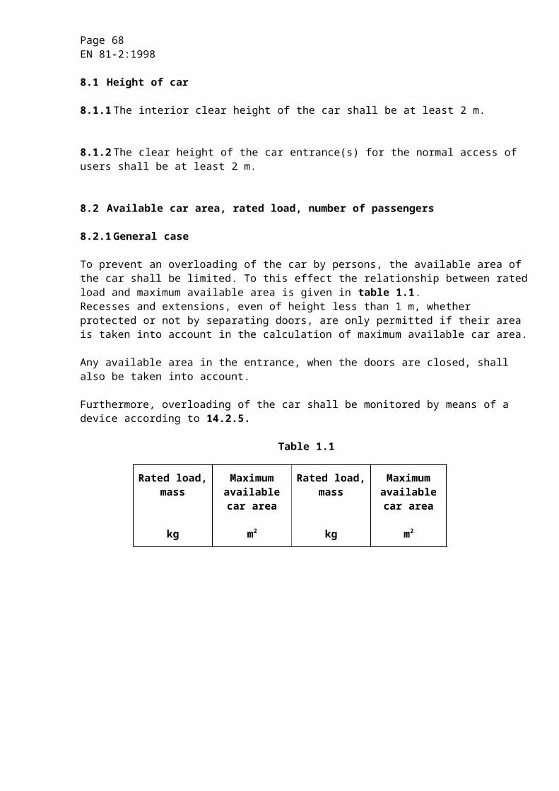
Page 68EN 81-2:1998
9.10.2.7.3 The requirement of 9.10.2.7.2 does not apply if the following three conditions are fulfilled :
a) the tripping of the overspeed governor according to 9.10.2.8 is effected by means of a remote control, except cableless, from outside the well, whereby an involuntary tripping is not effected and the actuation device is not accessible to unauthorised persons, and
b) the overspeed governor is accessible for inspection and maintenance from the roof of the car or from the pit, and
c) the overspeed governor returns after tripping automatically into the normal position, as the car or the balancing weight is moved in the upward direction.
However the electrical parts may return into the normal position by remote control from the outside of the well which shall not influence the normal function of the overspeed governor.
9.10.2.8 Possibility of tripping the overspeed governor
During checks or tests it shall be possible to operate the safety gear at a lower speed than that indicated in 9.10.2.1 by tripping the overspeed governor in a safe way.
9.10.2.9 If the overspeed governor is adjustable, the final setting shall be sealed.
9.10.2.10 Electrical checking
9.10.2.10.1The overspeed governor or another device shall, by means of an electric safety device in conformity with 14.1.2, initiate the stopping of the lift machine at latest at the moment when the tripping speed of the governor is reached.
9.10.2.10.2If after release of the safety gear (9.8.5.2) the overspeed governor does not automatically reset itself, an electric safety device in conformity with 14.1.2 shall prevent the starting of the lift while the overspeed governor is not in the reset position.
9.10.2.10.3The breakage or excessive rope stretch of the governor rope shall cause the machine to stop by means of an electric safety device in conformity with 14.1.2.
9.10.2.11 The overspeed governor is regarded as a safety component and shall be verified according to the requirements in F.4.
9.10.3 Tripping by the breakage of the suspension means
9.10.3.1 When springs are used for the tripping of the safety gear they shall be of the guided compression type.
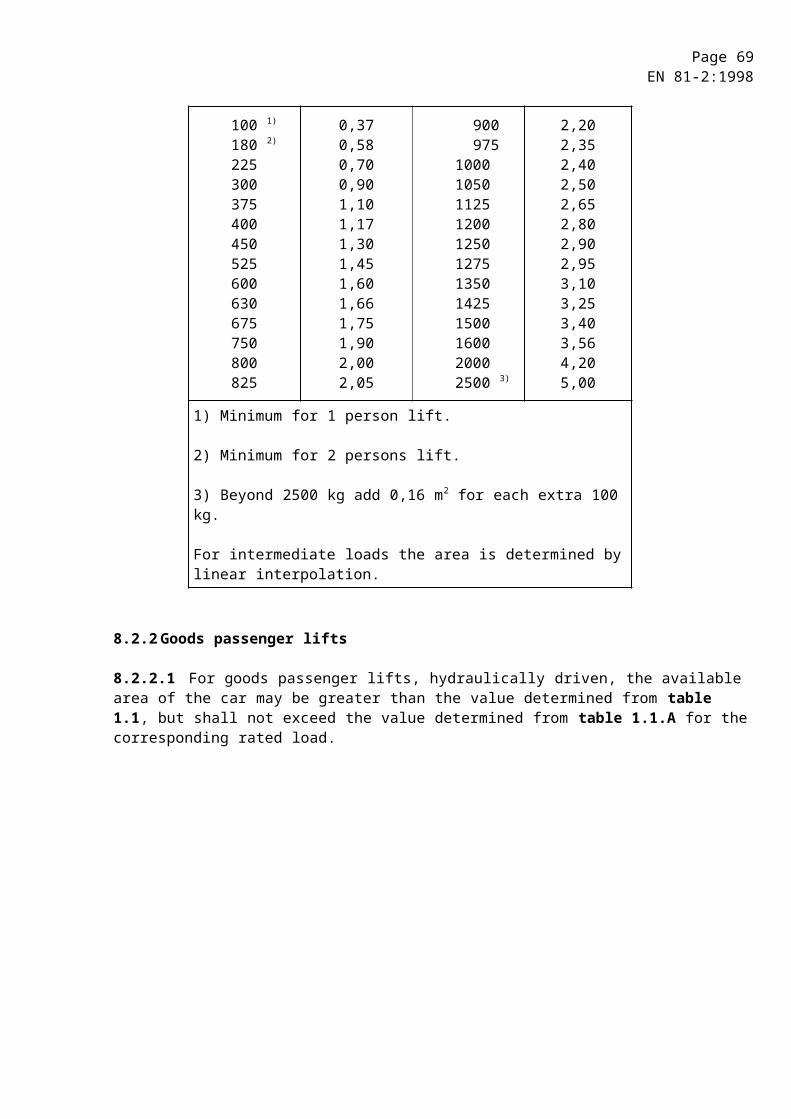
Page 69EN 81-2:1998
9.10.3.2 It shall be possible to make a test, triggered from outside the well, to show that the breakage of the suspension means will trip the safety gear.
9.10.3.3 In the case of indirect acting lifts with several jacks the breakage of the suspension means of any one of the jacks shall trip the safety gear.
9.10.4 Tripping by safety rope
9.10.4.1 The safety rope shall be in conformity with 9.10.6.
9.10.4.2 The rope shall be tensioned by gravity or by at least one guide compression spring.
9.10.4.3 During the engagement of the safety gear, the safety rope and its attachments shall remain intact, even in the case of a braking distance greater than normal.
9.10.4.4 The breakage or slackening of the safety rope shall cause the machine to stop by means of an electric safety device (14.1.2).
9.10.4.5 Pulleys used for carrying the safety rope shall be mounted independently of any shaft or pulley assembly that carries the suspension ropes or chains.
Protection devices shall be provided in accordance with 9.4.1.
9.10.5 Tripping by downward movement of the car
9.10.5.1 Tripping by rope
Tripping by rope of the safety gear or clamping device shall be actuated under the following conditions :
a) after a normal stop, a rope which satisfies 9.10.6 attached to the safety gear or clamping device shall be blocked with a force defined in 9.10.1 (for example, the overspeed governor rope) ;
b) the rope blocking mechanism shall be released during normal movement of the car ;
c) the rope blocking mechanism shall be actuated by guided compression spring(s) and/or by gravity ;
d) rescue operation shall be possible in all circumstances ;
e) an electric device associated with the rope blocking mechanism shall cause stopping of the machine at latest at the moment of blocking of the rope, and shall prevent any further normal downward movement of the car ;
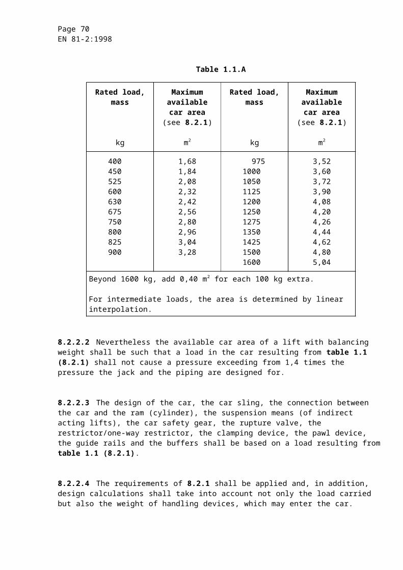
Page 70EN 81-2:1998
f) precautions shall be taken to avoid involuntary tripping of the safety gear, or clamping device, by the rope in case of the disconnection of the electric power supply during a downward movement of the car ;
g) the design of the system of rope and rope blocking mechanism shall be such that no damage is possible during the engagement of the safety gear, or clamping device ;
h) the design of the system of rope and rope blocking mechanism shall be such that no damage is possible by an upward movement of the car.
9.10.5.2 Tripping by lever
Tripping by lever of the safety gear or clamping device shall be actuated under the following conditions :
a) after the normal stopping of the car, a lever attached to the safety gear, or clamping device, shall be extended into a position to engage with fixed stops, which are located at each landing ;
b) the lever shall be retracted during the normal movement of the car ;
c) the movement of the lever to the extended position shall be effected by guided compression spring(s) and/or by gravity ;
d) emergency operation shall be possible in all circumstances ;
e) an electric device associated with the lever shall cause stopping of the machine at latest at the moment of lever extension, and shall prevent any further normal downward movement of the car ;
f) precautions shall be taken to avoid involuntary tripping of the safety gear, or clamping device, by the lever, in case of the disconnection of the electric power supply during a downward movement of the car ;
g) the design of the lever and stops system shall be such that no damage is possible during the engagement of the safety gear, or clamping device, even in the case of longer braking distances ;
h) the design of the lever and stops system shall be such that no damage is possible by an upward movement of the car.
9.10.6 Overspeed governor rope, safety rope
9.10.6.1 The rope shall be a wire rope designed for that purpose.
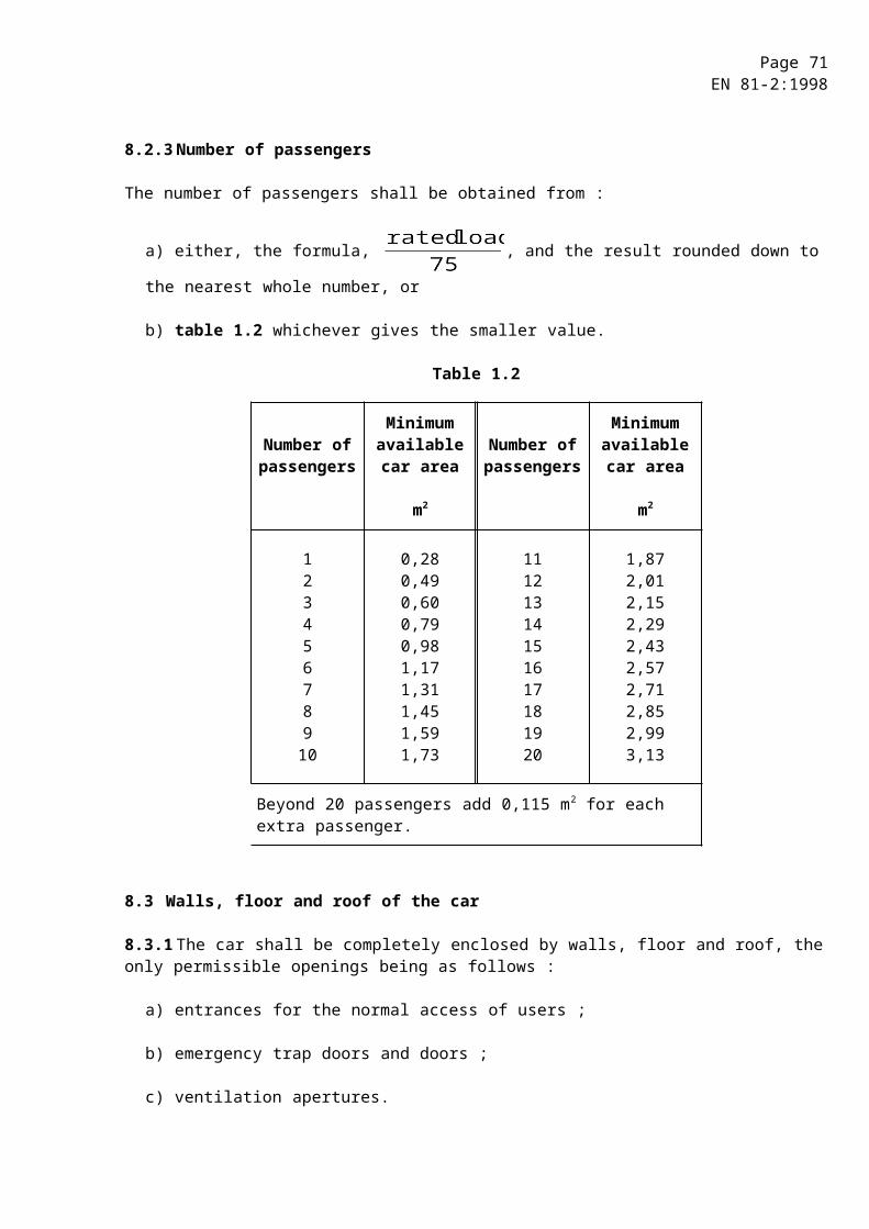
Page 71EN 81-2:1998
9.10.6.2 The minimum breaking load of the rope shall be related by a safety factor of at least 8 :
a) to the tensile force produced in the rope of the overspeed governor or the safety rope when tripped taking into account a friction factor mmax equal to 0,2 for traction type overspeed governor ;
b) to the force required to operate the safety gear or clamping device for safety ropes.
9.10.6.3 The nominal rope diameter shall be at least 6 mm.
9.10.6.4 The ratio between the pitch diameter of the pulleys for the overspeed governor rope and the nominal rope diameter shall be at least 30.
9.11 Pawl device
When required by 9.5, a pawl device shall be provided which satisfies the following conditions :
9.11.1 The pawl device shall operate only in the downward direction, and be capable of stopping the car, with a load according to table 1.1 (8.2.1) for lifts according to 8.2.1 and 8.2.2, and maintaining it stationary on fixed stops :
a) for lifts provided with a restrictor or one-way restrictor : from a speed of :
vd + 0,3 m/s, or
b) for all other lifts : from a speed equal to 115 % of downwards rated speed vd.
9.11.2 There shall be provided at least one electrically retractable pawl designed in its extended position to stop the downward moving car against fixed supports.
9.11.3 For each landing supports shall be provided arranged at two levels :
a) to prevent the car sinking below the landing level by more than 0,12 m, and
b) to stop the car at the lower end of the unlocking zone.
9.11.4 The movement of the pawl(s) to the extended position shall be effected by guided compression spring(s) and/or by gravity.
9.11.5 The supply to the electric retraction device shall be interrupted when the machine is stopped.
Page 72EN 81-2:1998
9.11.6 The design of the pawl(s) and supports shall be such that, whatever the position of the pawl, during upward movement the car cannot be stopped nor any damage caused.
9.11.7 A buffering system shall be incorporated in the pawl device (or in the fixed supports).
9.11.7.1 Buffers shall be of the following types :
a) energy accumulation, or
b) energy accumulation with buffered return movement, or
c) energy dissipation.
9.11.7.2 The requirements of 10.4 apply by analogy.
In addition, the buffer shall maintain the car stationary at a distance not exceeding 0,12 m below any loading level when carrying the rated load.
9.11.8 When several pawls are provided precautions shall be taken to ensure that all pawls engage on their respective supports even in the case of the disconnection of the electrical power supply during a downward movement of the car.
9.11.9 An electric device, which complies with the requirements of 14.1.2.2 or 14.1.2.3 shall prevent any normal down movement of the car when a pawl is not in the retracted position.
9.11.10 If energy dissipation buffers (9.11.7.1) are used, an electric device which complies with the requirements of 14.1.2.2 or 14.1.2.3 shall immediately initiate stopping of the machine if the car is travelling downwards and prevent starting of the machine in downward motion, when the buffer is not in its normal extended position. The power supply shall be interrupted according to 12.4.2.
9.11.11 Inclination of the car floor in case of pawl device operation.
The requirement of 9.8.7 applies by analogy.
9.12 Electrical anti-creep system
For electrical anti creep system, see 14.2.1.2 and 14.2.1.5.
10 Guide rails, buffers and final limit switch
10.1 General provisions concerning guide rails
10.1.1 The guide rails, their joints and attachments shall be sufficient to withstand the loads and forces imposed on them in order to ensure a safe operation of the lift.
Page 73EN 81-2:1998
The aspects of safe operation of the lift concerning guide rails are :
a) car- and balancing weight-guidance shall be assured ;
b) deflections shall be limited to such an extent, that due to them :
1) unintended unlocking of the doors shall not occur ;
2) operation of the safety devices shall not be affected, and
3) collision of moving parts with other parts shall not be possible.
Stresses shall be limited taking into account the distribution of the rated load in the car as given in G.2, G.3 and G.4 or according to the intended use as negotiated (0.2.5).
NOTE : Annex G describes a method of selecting guide rails.
10.1.2 Permissible stresses and deflections
10.1.2.1 The permissible stresses shall be determined by :
where :
= permissible stress in newtons per square millimetre ;
= tensile strength in newtons per square millimetre ;
= safety factor.
The safety factor has to be taken from table 4.
Table 4 : Safety factors for guide rails
Load cases Elongation (A5) Safety factor
Normal use A5 ³ 12 % 2,25
loading 8 % £ A5 £ 12 % 3,75
Safety gear A5 ³ 12 % 1,8
operation 8 % £ A5 £ 12 % 3,0
Materials with elongations less than 8 % are regarded as too brittle and shall not be used.
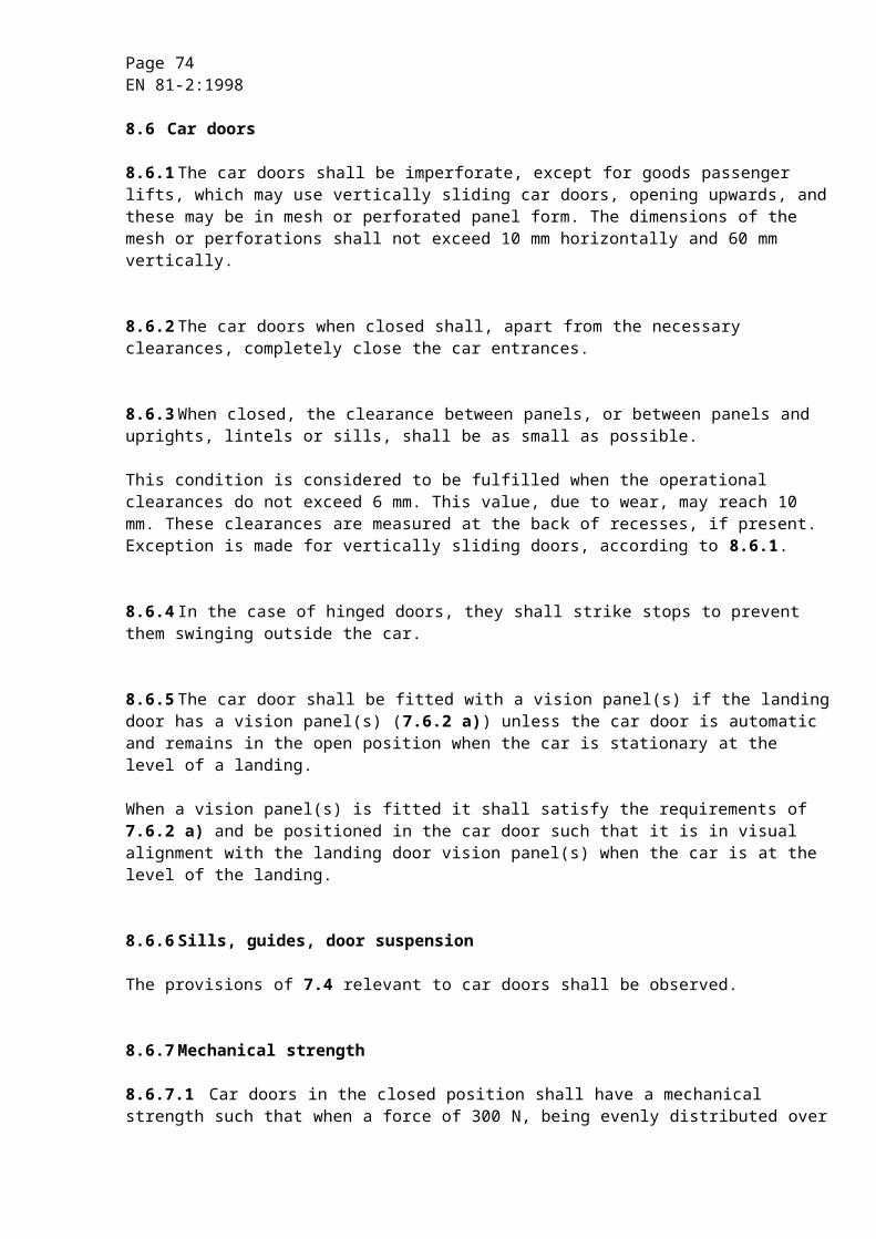
Page 74EN 81-2:1998
For guide rails in accordance with ISO 7465, the values of given in table 5 can be used.
Table 5 : Permissible stresses perm
Values in newtons per square millimetre
Load casesRm
370 440 520
Normal use loading 165 195 230
Safety gear operation 205 244 290
10.1.2.2 For T-profile guide rails the maximum calculated permissible deflections are :
a) 5 mm in both directions for car- and balancing weight guide rails on which safety gears are operating ;
b) 10 mm in both directions for guide rails of balancing weight without safety gears.
10.1.3 The fixing of the guide rails to their brackets and to the building shall permit compensation, either automatically or by simple adjustment, of effects due to normal settling of the building or shrinkage of concrete.
A rotation of the attachments by which the guide rails could be released shall be prevented.
10.2 Guiding of the car and balancing weight
10.2.1 The car and balancing weight shall each be guided by at least two rigid steel guide rails.
10.2.2 The guide rails shall be made from drawn steel, or the rubbing surfaces shall be machined, if :
a) the rated speed vs exceeds 0,4 m/s ;
b) progressive safety gears are used regardless of the speed.
10.2.3 Guide rails for balancing weights without safety gear may be made of formed metal sheet. They shall be protected against corrosion.
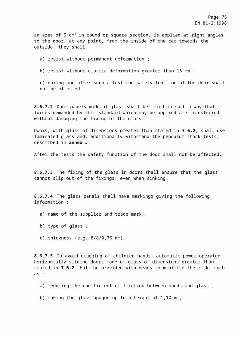
Page 75EN 81-2:1998
10.3 Car buffers
10.3.1 Lifts shall be provided with buffers at the bottom limit of travel of the car.
The acting point(s) of the buffer(s) below the projection of the car shall be made obvious by an obstacle (pedestal) of a height so that 5.7.2.3 is fulfilled. For buffers with the centre of the acting area within 0,15 m from the guide rails and similar fixed devices, excluding walls, these devices are regarded as obstacles.
10.3.2 When the buffer(s) of a pawl device is (are) used to limit the travel of the car at the bottom, this pedestal is also required unless the fixed stops of the pawl device are mounted on the car guide rails, and not able to pass with pawl(s) retracted.
10.3.3 The buffers shall maintain the car stationary at a distance not exceeding 0,120 m below the level of the lowest landing, when carrying the rated load.
10.3.4 When buffers are fully compressed the ram shall not hit the base of the cylinder.
This does not apply to devices ensuring re-synchronisation.
10.3.5 Buffers shall be of the following types :
a) energy accumulation, or
b) energy accumulation with buffered return movement, or
c) energy dissipation.
10.3.6 Energy accumulation type buffers, with linear and non-linear characteristics, shall only be used if the rated speed of the lift does not exceed 1 m/s.
10.3.7 Energy dissipation type buffers can be used whatever the rated speed of the lift.
10.3.8 The energy accumulation type buffers with non-linear characteristics and/or with buffered return movement and energy dissipation type buffers are regarded as safety components and shall be verified according to the requirements in F.5.
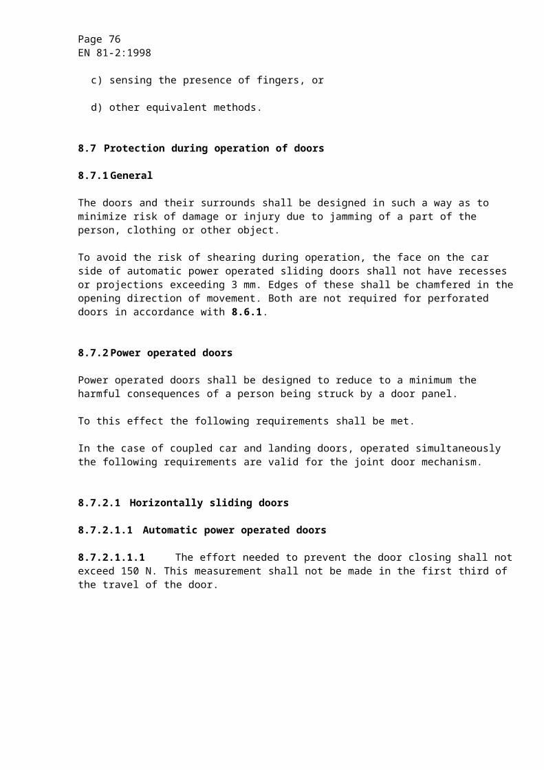
Page 76EN 81-2:1998
10.4 Stroke of car buffers
10.4.1 Energy accumulation type buffers
10.4.1.1 Buffers with linear characteristics
10.4.1.1.1 The total possible stroke of the buffers shall be :
a) for lifts provided with a restrictor (or one-way restrictor) :
at least equal to twice the gravity stopping distance corresponding to a value of speed given by the expression vd + 0,3 m/s, i.e. :
(stroke expressed in metres).
b) for all other lifts :
at least equal to twice the gravity stopping distance corresponding to 115 % of the rated speed 7) (0,135 vd
2), the stroke being expressed in metres.
However, the stroke shall not be less than 65 mm.
10.4.1.1.2 Buffers shall be designed to cover the stroke defined in 10.4.1.1.1, under a static load of between 2,5 and 4 times the sum of the mass of the car and the load according to table 1.1 (8.2.1) for lifts according to 8.2.1 and 8.2.2.
10.4.1.2 Buffers with non-linear characteristics
10.4.1.2.1 Energy accumulation type buffers with non-linear characteristics shall fulfil the following requirements :
a) hitting the car buffer with rated load in the car, in case of free fall with a speed according to 10.4.1.1.1, the average retardation shall not be more than 1 gn ;
b) retardation of more than 2,5 gn shall not be longer than 0,04 s ;
c) the return speed of the car shall not exceed 1 m/s ;
d) there shall be no permanent deformation after actuation.
10.4.1.2.2 The term “fully compressed”, mentioned in 5.7.1.2, 5.7.2.3, 10.3.4 and 12.2.5.2 means a compression of 90 % of the installed buffer height.
7) 2 = 0,1348 vd2 rounded to 0,135 vd
2.
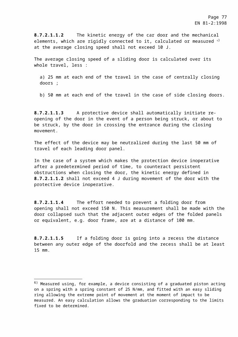
Page 77EN 81-2:1998
10.4.2 Energy accumulation type buffers with buffered return movement
The requirements of 10.4.1 apply to this type of buffer.
10.4.3 Energy dissipation type buffers
10.4.3.1 The total possible stroke of the buffers shall be :
a) for lifts provided with a restrictor (or one-way restrictor) :
at least equal to the gravity stopping distance corresponding to a value of speed given by the expression (vd + 0,3 m/s), i.e. :
(stroke expressed in metres) ;
b) for all other lifts :
at least equal to the gravity stopping distance corresponding to 115 % of the rated speed (0,067 vd
2), the stroke being expressed in metres.
10.4.3.2 Energy dissipation type buffers shall fulfil the following requirements
a) hitting the car buffer with a load in the car according to table 1.1 (8.2.1) for lifts according to 8.2.1 and 8.2.2, in case of free fall with a speed according to 10.4.3.1, the average retardation shall not be more than 1 gn ;
b) retardation of more than 2,5 gn shall not be longer than 0,04 s ;
c) there shall be no permanent deformation after actuation.
10.4.3.3 The normal operation of the lift shall depend on the return of the buffers to their normal extended position after operation. The device for checking this shall be an electric safety device in conformity with 14.1.2.
10.4.3.4 Buffers, if hydraulic, shall be so constructed that the fluid level can easily be checked.
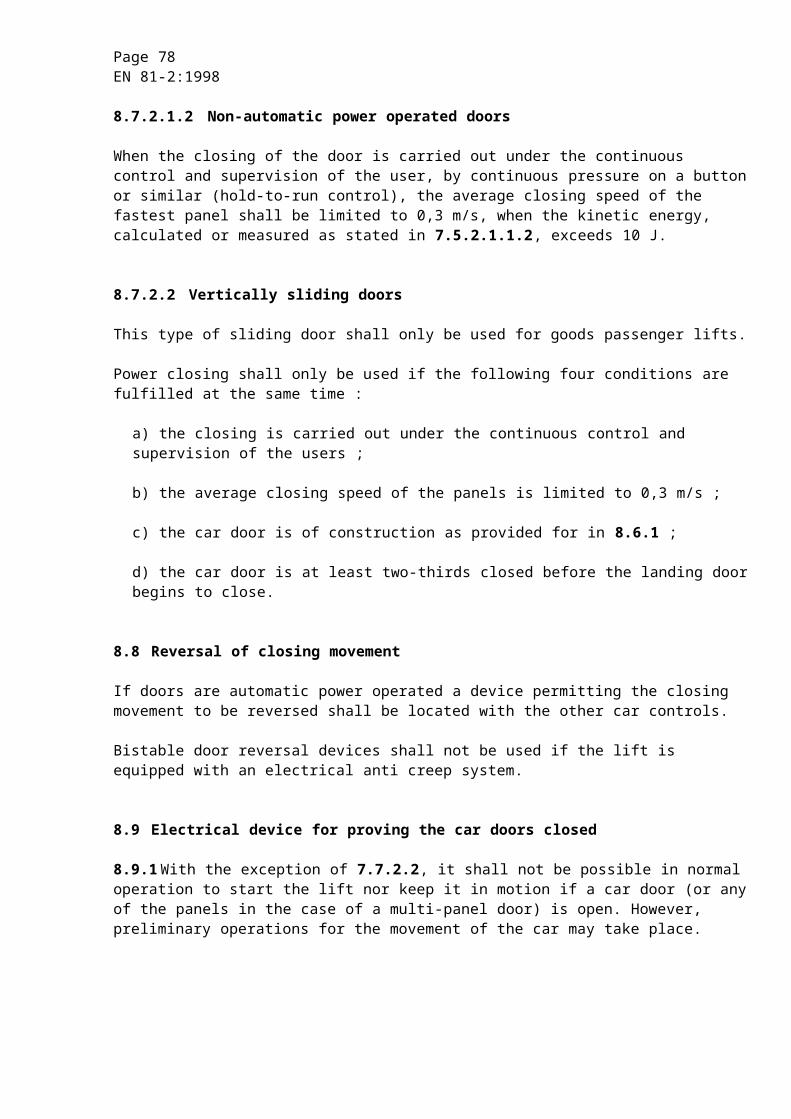
Page 78EN 81-2:1998
10.5 Final limit switch
10.5.1 General
A final limit switch shall be provided for the position of the ram corresponding to the upper end of the travel of the car. This switch shall :
a) be set to function as close as possible to the upper terminal floor, without risk of accidental operation ;
b) operate before the ram comes into contact with its cushioned stop (12.2.3).
The action of the final limit switch shall be maintained while the ram is in the zone of the cushioned stop.
10.5.2 Actuation of the final limit switch
10.5.2.1 Separate actuating devices shall be used for the upper normal terminal stopping device and the final limit switch.
10.5.2.2 In the case of direct acting lifts, actuation of the final limit switch shall be effected :
a) either directly by the car or the ram, or
b) indirectly by a device linked to the car, e.g. by a rope, belt or chain.
In the case b), breakage of, or slack in this linkage shall cause the machine to stop by means of an electric safety device in conformity with 14.1.2.
10.5.2.3 In the case of indirect acting lifts, actuation of the final limit switch shall be effected :
a) either directly by the ram, or
b) indirectly by a device linked to the ram, e.g. by a rope, belt or chain.
In the case b), breakage of or slack in this linkage shall cause the machine to stop by means of an electric safety device in conformity with 14.1.2.
10.5.3 Method of operation of final limit switch
10.5.3.1 The final limit switch shall be an electric safety device in conformity with 14.1.2 and shall, when actuated, stop the machine and keep it stopped. The final limit switch shall close automatically when the car leaves the actuation zone.
Page 79EN 81-2:1998
10.5.3.2 After the operation of the final limit switch car movement in response to car and landing calls only shall no longer be possible, even in the case of the car leaving the actuation zone by creeping. The return to service of the lift shall not occur automatically.
11 Clearances between car and wall facing the car entrance, and between car, balancing weight or balancing weight
11.1 General provision
The operational clearances specified in the standard shall be maintained not only during the examination and tests before the lift is put into service, but also throughout the life of the lift.
11.2 Clearances between car and wall facing the car entrance
The following requirements are illustrated in figure 4 and 5.
11.2.1 The horizontal distance between the inner surface of the lift well and the sill, door frame of the car or closing edge of car sliding doors shall not exceed 0,15 m.
The distance given above :
a) may be extended to 0,20 m over a height not exceeding 0,50 m ;
b) may be extended to 0,20 m throughout the travel on goods passenger lifts in which the landing doors are vertically sliding ;
c) is not limited if the car is provided with a mechanically locked door, which can only be opened in the unlocking zone of a landing door.
The operation of the lift shall automatically depend on the locking of the corresponding car door except in the cases covered in 7.7.2.2. This locking shall be proved by an electric safety device in conformity with 14.1.2.
11.2.2 The horizontal distance between the sill of the car and sill of the landing doors shall not exceed 35 mm.
11.2.3 The horizontal distance between the car door and the closed landing doors or the access distance between the doors during the whole of their normal operation shall not exceed 0,12 m.
11.2.4 In the case of the combination of a hinged landing door and a folding car door it shall not be possible to place a ball with a diameter of 0,15 m in any gap between the closed doors.
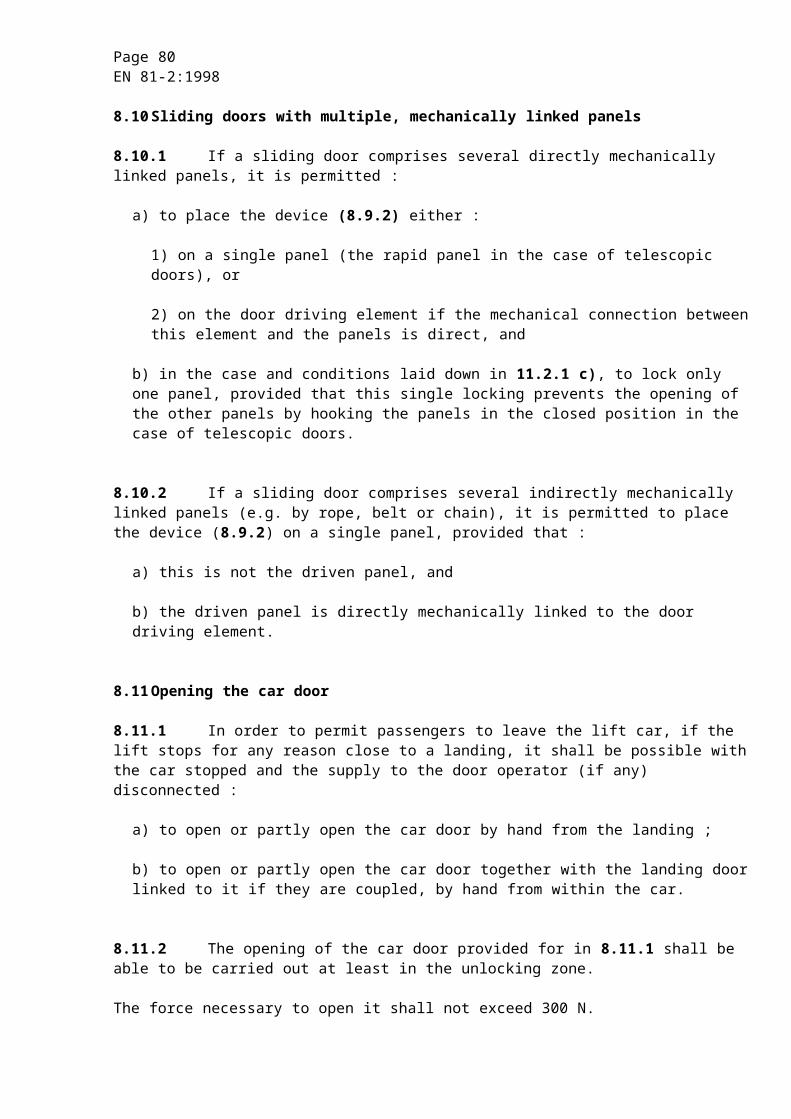
Page 80EN 81-2:1998
Figure 4 : Clearances between car and wall facing the car entrance
Figure 5 : Hinged landing door and folding car door - Gap
11.3 Clearances between car, balancing weight or balancing weight
The car and its associated components shall be at a distance of at least 50 mm from the balancing weight (if there is one) and its associated components.
12 Lift machine
12.1 General provisions
12.1.1 Each lift shall have at least one machine of its own.
The two following methods of drive are permissible :
a) direct acting ;
b) indirect acting.
Page 81EN 81-2:1998
12.1.2 If several jacks are used to raise the car they shall be hydraulically connected to ensure pressure equilibrium.
12.1.3 The mass of the balancing weight, if any, shall be calculated such that in case of a rupture of the suspension gear (car/balancing weight), the pressure in the hydraulic system does not exceed two times full load pressure.
In the case of several balancing weights, the rupture of only one suspension gear shall be taken into consideration for the calculation.
12.2 Jack
12.2.1 Calculations of cylinder and ram
12.2.1.1 Pressure calculations
12.2.1.1.1 The cylinder and the ram shall be designed such that under the forces resulting from a pressure equal to 2,3 times the full load pressure a safety factor of at least 1,7 referred to the proof stress RP0,2 is assured.
12.2.1.1.2 For the calculation 8) of the elements of telescopic jacks with hydraulic synchronizing means the full load pressure shall be replaced by the highest pressure, which occurs in an element due to the hydraulic synchronizing means.
12.2.1.1.3 In the thickness calculations a value shall be added of 1,0 mm for cylinder walls and cylinder bases, and 0,5 mm for walls of hollow rams for single and telescopic jacks.
12.2.1.1.4 The calculations shall be carried out according to annex K.
12.2.1.2 Buckling calculations
Jacks under compressive loads shall fulfil the following requirements :
12.2.1.2.1 They shall be designed such that, in their fully extended position, and under the forces resulting from a pressure equal to 1,4 times full load pressure a safety factor of at least two against buckling is assured.
12.2.1.2.2 The calculations shall be carried out according to annex K.
12.2.1.2.3 As a deviation from 12.2.1.2.2 more complex calculation methods may be used provided that at least the same safety factor is assured.
8) It may be possible that, due to incorrect adjustment of the hydraulic synchronizing means, abnormally high pressure conditions arise during installation. Account of this shall be taken.
Page 82EN 81-2:1998
12.2.1.3 Tensile stress calculations
Jacks under tensile loads shall be designed such that under the forces resulting from a pressure equal to 1,4 times full load pressure a safety factor of at least 2 referred to the proof stress RP0,2 is assured.
12.2.2 Connection car/ram (cylinder)
12.2.2.1 In case of a direct acting lift the connection between the car and the ram (cylinder) shall be flexible.
12.2.2.2 The connection between the car and the ram (cylinder) shall be so constructed to support the weight of the ram (cylinder) and the additional dynamic forces. The connection means shall be secured.
12.2.2.3 In case of a ram made with more than one section, the connections between the sections shall be so constructed to support the weight of the suspended ram sections and the additional dynamic forces.
12.2.2.4 In the case of indirect acting lifts, the head of the ram (cylinder) shall be guided.
This requirement does not apply for pulling jacks provided the pulling arrangement prevents bending forces on the ram.
12.2.2.5 In the case of indirect acting lifts, no parts of the ram head guiding system shall be incorporated within the vertical projection of the car roof.
12.2.3 Limitation of the ram stroke
12.2.3.1 Means shall be provided to stop the ram with buffered effect in such a position that the requirements of 5.7.1.1 can be satisfied.
12.2.3.2 This limitation of stroke shall either :
a) be by means of a cushioned stop, or
b) be effected by shutting off the hydraulic supply to the jack by means of a mechanical linkage between the jack and a hydraulic valve ; breakage or stretch of such a linkage shall not result in the retardation of the car exceeding the value specified in 12.2.3.3.2.
Page 83EN 81-2:1998
12.2.3.3 Cushioned stop
12.2.3.3.1 This stop shall either :
a) be an integral part of the jack, or
b) consist of one or more devices external to the jack situated outside the car projection, the resultant force of which is exerted on the centre line of the jack.
12.2.3.3.2 The design of the cushioned stop shall be such that the average retardation of the car does not exceed 1 gn and that in case of an indirect acting lift the retardation does not result in slack rope or chain.
12.2.3.4 In cases 12.2.3.2 b) and 12.2.3.3.1 b), a stop shall be provided inside the jack to prevent the ram from leaving the cylinder.
In the case of 12.2.3.2 b), this stop shall be positioned such that the requirements of 5.7.1.1 are also satisfied.
12.2.4 Means of protection
12.2.4.1 If a jack extends into the ground it shall be installed in a protective tube. If it extends into other spaces it shall be suitably protected.
In the same manner :
a) the rupture valve(s)/restrictor(s) ;
b) the rigid pipes connecting a rupture valve(s)/restrictor(s) with the cylinder ;
c) the rigid pipes connecting rupture valve(s)/restrictor(s) with each other ;
shall be protected.
12.2.4.2 Leak and scrape fluid from the cylinder head shall be collected.
12.2.4.3 The jack shall be provided with an air venting device.
12.2.5 Telescopic jacks
The following requirements apply additionally :
12.2.5.1 Stop shall be provided between successive sections to prevent the rams from leaving their respective cylinders.
Page 84EN 81-2:1998
12.2.5.2 In the case of a jack below the car of a direct acting lift, the clear distance :
a) between the successive guiding yokes, and
b) between the highest guiding yoke and the lowest parts of the car (parts mentioned in 5.7.2.3 b) 2) excluded) ;
shall be at least 0,30 m when the car rests on its fully compressed buffers.
12.2.5.3 The length of the bearing of each section of a telescopic jack without external guidance shall be at least 2 times the diameter of the respective ram.
12.2.5.4 These jacks shall be provided with mechanical or hydraulic synchronizing means.
12.2.5.5 When jacks with hydraulic synchronizing means are used an electric device shall be provided to prevent a start for a normal journey when the pressure exceeds the full load pressure by more than 20 %.
12.2.5.6 When ropes or chains are used as synchronizing means the following requirements apply :
a) there shall be at least two independent ropes or chains ;
b) the requirements of 9.4.1 apply ;
c) the safety factor shall be at least :
1) 12 for ropes ;
2) 10 for chains.
The safety factor is the ratio between the minimum breaking load in newtons of one rope (or chain) and the maximum force in this rope (or chain).
For the calculation of the maximum force the following shall be taken into consideration :
- the force resulting from the full load pressure ;
- the number of ropes (or chains) ;
d) a device shall be provided which prevents the speed of the car in downward movement exceeding the rated speed downward vd by more than 0,3 m/s in the event of failure of the synchronizing means.
Page 85EN 81-2:1998
12.3 Piping
12.3.1 General
12.3.1.1 Piping and fittings, which are subject to pressure (connections, valves, etc.) as in general all components of the hydraulic system shall :
a) be appropriate to the hydraulic fluid used ;
b) be designed and installed in such a way to avoid any abnormal stress due to fixing, torsion or vibration ;
c) be protected against damage, in particular of mechanical origin.
12.3.1.2 Pipes and fittings shall be appropriately fixed and accessible for inspection.
If pipes (either rigid or flexible) pass through walls or floor they shall be protected by means of ferrules, the dimensions of which allow the dismantling, if necessary, of the pipes for inspection.
No coupling shall be sited inside a ferrule.
12.3.2 Rigid pipes
12.3.2.1 Rigid pipes and fittings between cylinder and non-return valve or down direction valve(s) shall be designed such that under the forces resulting from a pressure equal to 2,3 times the full load pressure a safety factor of at least 1,7 referred to the proof stress RP0,2 is assured.
In the thickness calculations a value shall be added of 1,0 mm for the connection between the cylinder and the rupture valve, if any, and 0,5 mm for the other rigid pipes.
The calculations shall be carried out according to K.1.1.
12.3.2.2 When telescopic jacks with more than 2 stages and hydraulic synchronizing means are used an additional safety factor of 1,3 shall be taken into account for the calculation of the pipes and fittings between the rupture valve and the non-return valve or the down direction valve(s).
Pipes and fittings, if any, between the cylinder and the rupture valve shall be calculated on the same pressure basis as the cylinder.
12.3.3 Flexible hoses
12.3.3.1 The flexible hose between cylinder and non-return valve or down direction valve shall be selected with a safety factor of at least 8 relating full load pressure and bursting pressure.
12.3.3.2 The flexible hose and its couplings between cylinder and non-return valve or down direction valve shall withstand without damage a pressure of five times full load pressure, this test to be carried out by the manufacturer of the hose assembly.
Page 86EN 81-2:1998
12.3.3.3 The flexible hose shall be marked in an indelible manner with :
a) the name of the manufacturer or the trade mark ;
b) the test pressure ;
c) the date of the test.
12.3.3.4 The flexible hose shall be fixed with a bending radius not less than that indicated by the hose manufacturer.
12.4 Stopping the machine and checking its stopped condition
A stop of the machine due to the operation of an electrical safety device, in conformity with 14.1.2, shall be controlled as detailed below.
12.4.1 Upwards motion
For upwards motion, either :
a) the supply to the electric motor shall be interrupted by at least two independent contactors, the main contacts of which shall be in series in the motor supply circuit, or
b) the supply to the electric motor shall be interrupted by one contactor, and the supply to the by-pass valves (in accordance with 12.5.4.2) shall be interrupted by at least two independent electrical devices connected in series in the supply circuit of these valves.
12.4.2 Downwards motion
For downwards motion, the supply to the down direction valve(s) shall be interrupted either :
a) by at least two independent electrical devices connected in series, or
b) directly by the electrical safety device, provided it is suitable rated electrically.
12.4.3 If whilst the lift is stationary, one of the contactors has not opened the main contacts or one of the electrical devices has not opened, a further start shall be prevented, at the latest at the next change in the direction of motion.
12.5 Hydraulic control and safety devices
12.5.1 Shut-off valve
12.5.1.1 A shut-off valve shall be provided. It shall be installed in the circuit which connects the cylinder(s) to the non-return valve and the down direction valve(s).
Page 87EN 81-2:1998
12.5.1.2 It shall be located in the machine room.
12.5.2 Non-return valve
12.5.2.1 A non-return valve shall be provided. It shall be installed in the circuit between the pump(s) and the shut-off valve.
12.5.2.2 The non-return valve shall be capable of holding the lift car with the rated load at any point when the supply pressure drops below the minimum operating pressure.
12.5.2.3 The closing of the non-return valve shall be effected by the hydraulic pressure from the jack and by at least one guided compression spring and/or by gravity.
12.5.3 Pressure relief valve
12.5.3.1 A pressure relief valve shall be provided. It shall be connected to the circuit between the pump(s) and the non-return valve. The hydraulic fluid shall be returned to the tank.
12.5.3.2 The pressure relief valve shall be adjusted to limit the pressure to 140 % of the full load pressure.
12.5.3.3 If necessary due to high internal losses (head loss, friction), the pressure relief valve may be set to a greater value but not exceeding 170 % of full load pressure. In this case, for the calculations of the hydraulic equipment (including jack) a fictitious full load pressure equal to :
shall be used.
In the buckling calculation the over pressure factor of 1,4 shall then be replaced by a factor corresponding to the increased setting of the pressure relief valve.
12.5.4 Direction valves
12.5.4.1 Down direction valves
Down direction valves shall be held open electrically. Their closing shall be effected by the hydraulic pressure from the jack and by at least one guided compression spring per valve.

Page 88EN 81-2:1998
12.5.4.2 Up direction valves
If the stopping of the machine is effected in accordance with 12.4.1 b), only by-pass valves shall be used for this. They shall be closed electrically. Their opening shall be effected by the hydraulic pressure from the jack and by at least one guided compression spring per valve.
12.5.5 Rupture valve
When required by 9.5, a rupture valve shall be provided which satisfies the following conditions :
12.5.5.1 The rupture valve shall be capable of stopping the car in downward movement, and maintaining it stationary. The rupture valve shall be tripped at the latest when the speed reaches a value equal to rated speed downwards vd plus 0,3 m/s.
The rupture valve shall be selected so that the average retardation a lies between 0,2 gn and 1 gn.
Retardation of more than 2,5 gn shall not last longer than 0,04 s.
The average retardation a can be evaluated by the formula :
a =
where :
Qmax = maximum flow in litres per minute ;
r = reeving factor ;
A = area of jack, where pressure is acting in square centimetres ;
n = number of parallel acting jacks with one rupture valve ;
td = braking time in seconds ;
the values of which can be taken from the technical dossier and the type examination certificate.
12.5.5.2 The rupture valve shall be accessible for adjustment and inspection.
The rupture valve shall be either :
a) integral with the cylinder, or
b) directly and rigidly flange-mounted, or
c) placed close to the cylinder and connected to it by means of short rigid pipes, having welded, flanged or threaded connections, or
Page 89EN 81-2:1998
d) connected directly to the cylinder by threading.
The rupture valve shall be provided with a thread ending with a shoulder. The shoulder shall butt up against the cylinder.
Other types of connections such as compression fittings or flared fittings are not permitted between the cylinder and the rupture valve.
12.5.5.4 On lifts with several jacks, operating in parallel, one common rupture valve may be used. Otherwise the rupture valves shall be interconnected to cause simultaneous closing, in order to avoid the floor of the car from inclining by more than 5 % from its normal position.
12.5.5.5 The rupture valve shall be calculated as the cylinder.
12.5.5.6 If the closing speed of the rupture valve is controlled by a restricting device a filter shall be located as near as possible before this device.
12.5.5.7 There shall be in the machine room a manually operated means allowing to reach the tripping flow of the rupture valve without overloading the car. The means shall be safeguarded against unintentional operation. It shall not neutralise the safety devices adjacent to the jack.
12.5.5.8 The rupture valve is regarded as a safety component and shall be verified according to the requirements in F.7.
12.5.6 Restrictor, also one-way restrictor
When required by 9.5, a restrictor/one-way restrictor shall be provided which satisfies the following conditions :
12.5.6.1 In the case of a major leakage in the hydraulic system the restrictor shall prevent the speed of the car with rated load in downward movement exceeding the rated speed downwards vd by more than 0,3 m/s.
12.5.6.2 The restrictor shall be accessible for inspection.
12.5.6.3 The restrictor shall be either :
a) integral with the cylinder, or
b) directly and rigidly flange-mounted, or
c) placed close to the cylinder and connected to it by means of short rigid pipes, having welded, flanged or threaded connections, or

Page 90EN 81-2:1998
d) connected directly to the cylinder by threading.
The restrictor shall be provided with a thread ending with a shoulder. This shall butt up against the cylinder.
Other types of connections such as compression fittings or flared fittings are not permitted between the cylinder and the restrictor.
12.5.6.4 The restrictor shall be calculated as the cylinder.
12.5.6.5 There shall be in the machine room a manually operated means allowing to reach the tripping flow of restrictor without overloading the car. The means shall be safeguarded against unintentional operation. In no case shall it neutralise the safety devices adjacent to the jack.
12.5.6.6 Only the one-way restrictor where mechanical moving parts are used is regarded as a safety component and shall be verified according to the requirements in F.7.
12.5.7 Filters
In the circuit between the tank and the pump(s), and in the circuit between the shut-off valve and the down direction valve(s), filters or similar devices shall be installed. The filter or similar device between the shut-off valve and the down direction valve shall be accessible for inspection and maintenance.
12.6 Checking the pressure
12.6.1 A pressure gauge shall be provided. It shall be connected to the circuit between the non-return valve or the down direction valve(s) and the shut-off valve.
12.6.2 A gauge shut-off valve shall be provided between the main circuit and the connection for the pressure gauge.
12.6.3 The connection shall be provided with an internal thread of either M 20 x 1,5 or G 1/2”.
12.7 Tank
The tank shall be designed and constructed for :
a) easy check of the level of the hydraulic fluid in the tank ;
b) easy filling and draining.
Page 91EN 81-2:1998
12.8 Speed
12.8.1 The rated speed upwards vm or downwards vd shall not be greater than 1,0 m/s (see 1).
12.8.2 The speed of the empty car upwards shall not exceed the rated upward speed vm by more than 8 %, and the speed of the car with rated load downwards shall not exceed the rated downward speed vd by more than 8 %, in each case this relates to the normal operating temperature of the hydraulic fluid.
For a journey in the upward direction it is supposed that the supply is at its rated frequency and that the motor voltage is equal to the rated voltage of the equipment.
12.9 Emergency operation
12.9.1 Moving the car downwards
12.9.1.1 The lift shall be provided with a manually operated emergency lowering valve located in the machine room allowing the car, even in the case of a power failure, to be lowered to a level where the passengers can leave the car.
12.9.1.2 The speed of the car shall not exceed 0,3 m/s.
12.9.1.3 The operation of this valve shall require a continual manual force.
12.9.1.4 This valve shall be protected against involuntary action.
12.9.1.5 In the case of indirect acting lifts where slack rope/chain can occur, manual operation of the valve shall not cause the sinking of the ram beyond that causing the slack rope/chain.
12.9.2 Moving the car upwards
12.9.2.1 A hand-pump which causes the car to move in the upwards direction shall be permanently installed for every lift whose car is fitted with a safety gear or a clamping device.
12.9.2.2 The hand-pump shall be connected to the circuit between the non-return valve or down direction valve(s) and the shut-off valve.
12.9.2.3 The hand-pump shall be equipped with a pressure relief valve limiting the pressure to 2,3 times the full load pressure.
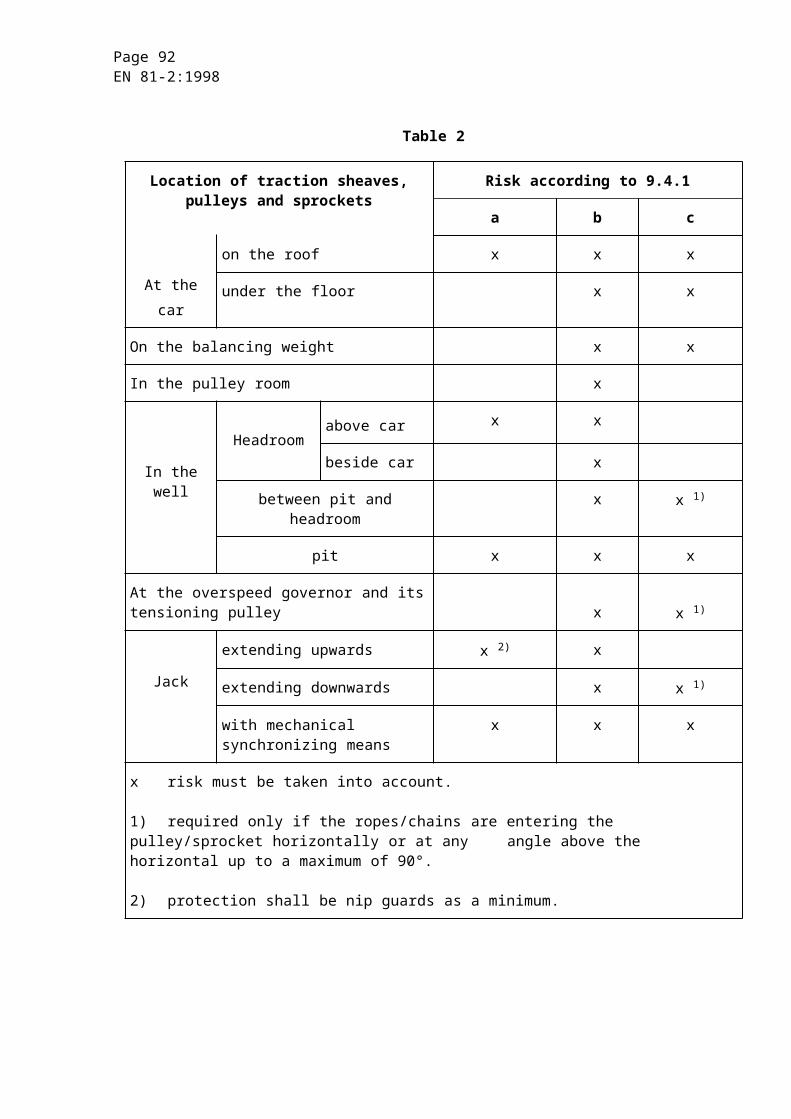
Page 92EN 81-2:1998
12.9.3 Checking of the car position
If the lift serves more than two levels, it shall be possible to check from the machine room whether the car is in an unlocking zone by a means, which is independent of the power supply.
This requirement is not applicable to lifts, which are fitted with a mechanical anti-creep device.
12.10Protection of the pulley(s) or sprocket(s) on the jack
Devices according to 9.4 shall be provided.
12.11Protection of machinery
Effective protection shall be provided for accessible rotating parts, which may be dangerous, in particular :
a) keys and screws in the shafts ;
b) tapes, chains, belts ;
c) gears, sprockets ;
d) projecting motor shafts ;
e) fly-ball type overspeed governors.
12.12Motor run time limiter
12.12.1 Hydraulic lifts shall have a motor run time limiter causing the de-energizing of the motor, and keep it de-energized, if the motor does not rotate when a start is initiated.
12.12.2 The motor run time limiter shall function in a time which does not exceed the smaller of the following two values :
a) 45 s ;
b) time for travelling the full travel with rated load, plus 10 s, with a minimum of 20 s if the full travel time is less than 10 s.
12.12.3 The return to normal service shall only be possible by manual resetting. On restoration of the power after a supply disconnection, maintaining the machine in the stopped position is not necessary.
12.12.4 The motor run time limiter, even if tripped, shall not prevent the inspection operation (14.2.1.3) and the electrical anti-creep system (14.2.1.5 a) and b)).
Page 93EN 81-2:1998
12.13Slack rope (or chain) safety device for indirect acting lifts
If the risk of slack rope (or chain) exists, an electric safety device in conformity with 14.1.2 shall be provided. This device shall cause the machine to stop and keep it stopped when slack occurs.
12.14Protection against overheating of the hydraulic fluid
A temperature detecting device shall be provided. This device shall stop the machine and keep it stopped in accordance with 13.3.5.
13 Electric installations and appliances
13.1 General provisions
13.1.1 Limits of application
13.1.1.1 The requirements of this standard relating to the installation and to the constituent components of the electrical equipment apply :
a) to the main switch of the power circuit and dependent circuits ;
b) to the switch for the car lighting circuit and dependent circuits.
The lift shall be considered as a whole, in the same way as a machine with its built in electrical equipment.
NOTE : The national requirements relating to electricity supply circuits apply as far as the input terminals of the switches. They apply to the whole lighting and socket outlet circuits of the machine room, the pulley room and the lift well and pit.
13.1.1.2 The requirements of this standard for circuits dependent on the switches referred to in 13.1.1.1 are based, as far as possible, taking into account the specific needs of lifts, on existing standards :
a) on the international level : IEC ;
b) on the European level : CENELEC.
Whenever one of these standards is used, its references are given, together with the limits within which it is used.
When no precise information is given, the electrical equipment used shall conform to the accepted Codes of Practice relating to safety.
13.1.1.3 The electromagnetic compatibility shall comply with the requirements of EN 12015 and EN 12016.
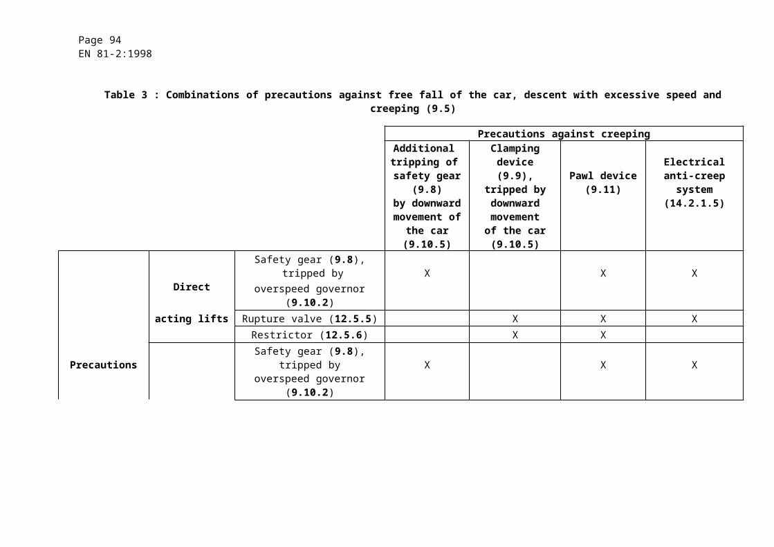
Page 94EN 81-2:1998
13.1.2 In the machine and pulley rooms protection against direct contact shall be provided, by means of casings providing a degree of protection of at least IP 2X.
13.1.3 Insulation resistance of the electrical installation (CENELEC HD 384.6.61 S1)
The insulation resistance shall be measured between each live conductor and earth.
Minimum values of insulation resistance shall be taken from table 6.
Table 6
Nominal circuit voltage V
Test voltage (d.c.)V
Insulation resistance MW
SELV 250 ³ 0,25
£ 500 500 ³ 0,5
> 500 1000 ³ 1,0
When the circuit includes electronic devices, phase and neutral conductors shall be connected together during measurement.
13.1.4 The mean value in direct current or the r.m.s. value in alternating current of the voltage between conductors or between conductors and earth, shall not exceed 250 V for control and safety circuits.
13.1.5 The neutral conductor and the protection conductor shall always be separate.
13.2 Contactors, relay-contactors, components of safety circuits
13.2.1 Contactors and relay-contactors
13.2.1.1 The main contactors, i.e. those necessary to stop the machine as per 12.4, shall belong to the following categories as defined in EN 60947-4-1 :
a) AC-3 for contactors for A.C. motors ;
b) DC-3 for contactors for D.C. power.
These contactors shall, in addition allow 10 % of starting operations to be made as inching.
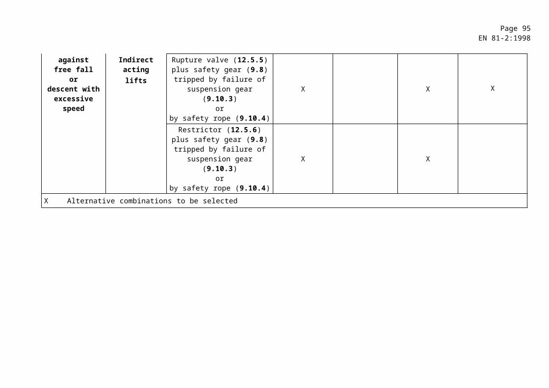
Page 95EN 81-2:1998
13.2.1.2 If, because of the power they carry, relay-contactors are used to operate the main contactors, those relay-contactors shall belong to the following categories as defined in EN 60947-5-1 :
a) AC-15 for controlling A.C. electromagnets ;
b) DC-13 for controlling D.C. electromagnets.
13.2.1.3 Both for the main contactors referred to in 13.2.1.1 and for the relay-contactors referred to in 13.2.1.2, it may be assumed in the measures taken to comply with 14.1.1.1 that :
a) if one of the break contacts (normally closed) is closed, all the make contacts are open ;
b) if one of the make contacts (normally open) is closed, all the break contacts are open.
13.2.2 Components of safety circuits
13.2.2.1 When relay-contactors as per 13.2.1.2 are used, as relays in a safety circuit, the assumptions of 13.2.1.3 shall also apply.
13.2.2.2 If relays are used which are such that the break and make contacts are never closed simultaneously for any position of the armature, the possibility of partial attraction of the armature (14.1.1.1 f)) can be disregarded.
13.2.2.3 Devices (if any) connected after electrical safety devices shall meet the requirements of 14.1.2.2.3 as regards the creepage distances and the air gaps (not the separation distances).
This requirement does not apply to the devices mentioned in 13.2.1.1, 13.2.1.2 and 13.2.2.1 and which themselves fulfil the requirements of EN 60947-4-1 and EN 60947-5-1.
For printed circuit boards requirements as mentioned in table H.1 (3.6) are applicable.
13.3 Protection of motors and other electrical equipment
13.3.1 Motors directly connected to the mains shall be protected against short-circuiting.
13.3.2 Motors directly connected to the mains shall be protected against overloads by means of manual reset (except as provided for in 13.3.3) automatic circuit-breakers which shall cut off the supply to the motor in all live conductors.
13.3.3 When the detection of overloads of the lift motor operates on the basis of increase of the temperature of the motor windings the interruption of the motor supply shall only occur in accordance with 13.3.5.
Page 96EN 81-2:1998
13.3.4 The provisions of 13.3.2 and 13.3.3 apply to each winding if the motor has windings supplied by different circuits.
13.3.5 If the design temperature of an electrical equipment provided with a temperature monitoring device is exceeded and the lift should not continue in operation, then the car shall stop at a landing such as the passengers can leave the car. An automatic return to normal operation of the lift in upwards direction shall only occur after sufficient cooling down.
13.4 Main switches
13.4.1 Machine rooms shall contain, for each lift, a main switch capable of breaking the supply to the lift on all the live conductors. This switch shall be capable of interrupting the highest current involved in normal conditions of use of the lift.
This switch shall not cut the circuits feeding :
a) car lighting or ventilation, if any ;
b) socket outlet on the car roof ;
c) lighting of machine and pulley rooms ;
d) socket outlet in the machine room, in the pulley room and in the pit ;
e) lighting of the lift well ;
f) alarm device.
13.4.2 The main switches as defined in 13.4.1 shall have stable open and closed positions, and shall be capable of being locked-off in the open position, with the use of a padlock or equivalent, to ensure no inadvertent operation.
The control mechanism for the main switch shall be easily and rapidly accessible from the entrance(s) to the machine room. If the machine room is common to several lifts, the control mechanism of the main switches shall allow the lift concerned to be identified easily.
If the machine room has several points of access, or if the same lift has several machine rooms each with its own point(s) of access, a circuit breaker contactor may be used, release of which shall be controlled by an electric safety device, in conformity with 14.1.2, inserted in the supply circuit to the coil of the circuit breaker contactor.
The re-engagement of the circuit breaker contactor shall not be carried out or made possible except by means of the device, which caused its release. The circuit-breaker contactor shall be used in conjunction with a manually controlled isolating switch.
13.4.3 In the case of a group of lifts, if, after the opening of the main switch for one lift, parts of the operating circuits remain live, these circuits shall be capable of being separately isolated in the machine room, if necessary by breaking the supply to all the lifts in the group.

Page 97EN 81-2:1998
13.4.4 Any capacitors to correct the power factor shall be connected before the main switch of the power circuit.
If there is a risk of over-voltage, when for example the motors are connected by very long cables, the switch of the power circuit shall also interrupt the connection to the capacitors.
13.5 Electric wiring
13.5.1 In the machine and pulley rooms and lift wells, the conductors and cables (with the exception of travelling cables) shall be selected from those standardized by CENELEC and of a quality at least equivalent to that defined by HD 21.3 S3 and HD 22.4 S3 taking into account the information given in 13.1.1.2.
13.5.1.1 Conductors such as those in conformity with CENELEC HD 21.3 S3, parts 2(H07V-U and H07V-R), 3 (H07V-K), 4 (H05V-U) and 5 (H05V-K) shall only be used provided they are installed in conduits (or trunking) made either of metal or plastics or the conductors are protected in an equivalent manner.
NOTE : These provisions replace those in the guide to use appearing in annex 1 of CENELEC HD 21.1 S3.
13.5.1.2 Rigid cables such as those in conformity with 2 of CENELEC HD 21.4 S2 shall only be used in visible mountings fixed to the walls of the well (or of the machine room) or installed in ducting, trunking or similar fittings.
13.5.1.3 Ordinary flexible cables such as those in conformity with 3 (H05RR-F) of CENELEC HD 22.4 S3 and 5 (H05VV-F) of CENELEC HD 21.5 S3, shall only be used in ducting, trunking or fittings ensuring equivalent protection.
Flexible cables with a thick sheath such as those in conformity with 5 (H07RN-F) of CENELEC HD 22.4 S3 may be used like rigid cables in the conditions defined in 13.5.1.2, and for connection to a movable appliance (except as travelling cables for connection to the car) or if they are subject to vibrations.
Travelling cables in conformity with EN 50214 and CENELEC HD 360 S2 shall be accepted as cables for connection to the car, within the limits laid down by these documents. In all cases, the travelling cables selected shall be of at least equivalent quality.
13.5.1.4 The requirements of 13.5.1.1, 13.5.1.2 and 13.5.1.3 need not apply :
a) to conductors or cables not connected to electric safety devices on landing doors, provided that :
1) they are not subject to a rated output of more than 100 VA ;
2) the voltage, between poles (or phases) or between a pole (or one of the phases) and earth, to which they are normally subject does not exceed 50 V ;
Page 98EN 81-2:1998
b) to the wiring of operating or distribution devices in cabinets or on panels :
1) either between different pieces of electric equipment, or
2) between these pieces of equipment and the connection terminals.
13.5.2 Cross-sectional area of conductors
In order to provide mechanical strength the cross-sectional area of conductors to electric safety devices of doors shall not be less than 0,75 mm2.
13.5.3 Method of installation
13.5.3.1 The electric installation shall be provided with the indications necessary to make it easy to understand.
13.5.3.2 Connections, connection terminals and connectors, except those defined in 13.1.1.1, shall be located in cabinets, boxes or on panels provided for this purpose.
13.5.3.3 If, after the opening of the main switch or switches of a lift, some connection terminals remain live, they shall be clearly separated from terminals, which are not live, and if the voltage exceeds 50 V, they shall be suitably marked.
13.5.3.4 Connection terminals whose accidental interconnection could lead to a dangerous malfunction of the lift shall be clearly separated unless their method of construction obviates this risk.
13.5.3.5 In order to ensure continuity of mechanical protection, the protective sheathing of conductors and cables shall fully enter the casings of switches and appliances, or shall terminate in a suitably constructed gland.
NOTE : Enclosed frames of landing and car doors are regarded as appliance casings.
However, if there is a risk of mechanical damage due to movement of parts or sharp edges of the frame itself, the conductors connected to the electric safety device shall be protected mechanically.
13.5.3.6 If the same ducting or cable contain conductors whose circuits have different voltages, all the conductors or cables shall have the insulation specified for the highest voltage.
13.5.4 Connectors
Connectors and devices of the plug-in type placed in safety circuits shall be so designed and arranged that, if erroneous interconnection could lead to dangerous malfunction of the lift, or their withdrawal does not require the use of a tool, it is impossible to re-insert the plug incorrectly.
Page 99EN 81-2:1998
13.6 Lighting and socket outlets
13.6.1 The electric lighting supplies to the car, the well and the machine and pulley rooms, shall be independent of the supply to the machine, either through another circuit or through connection to the machine supply circuit on the supply side of the main switch or the main switches laid down in 13.4.
13.6.2 The supply to socket outlets required on the car roof, in the machine and pulley rooms and in the pit, shall be taken from the circuits referred to in 13.6.1.
These socket outlets are :
a) either of type 2 P + PE, 250 V, supplied directly, or
b) supplied at a safety extra-low voltage (SELV) in accordance with CENELECHD 384.4.41 S2, subclause 411.
The use of the above socket outlets does not imply that the supply cable has a cross-sectional area corresponding to the rated current of the socket outlet. The cross-sectional area of the conductors may be smaller, provided that the conductors are correctly protected against excess currents.
13.6.3 Control of the supply for lighting and socket outlets
13.6.3.1 A switch shall control the supply to the circuit for lighting and socket outlets of the lift car. If the machine room contains several lift machines it is necessary to have one switch per car. This switch shall be located close to the corresponding main power switch.
13.6.3.2 In the machine room a switch or a similar device shall be located near its access(es) controlling the supply for lighting.
For the well lighting switches (or equivalent) shall be located both at the machine room and pit so that the well light can be operated from either location.
13.6.3.3 Each circuit controlled by the switches laid down in 13.6.3.1 and 13.6.3.2 shall have its own short circuit protection.
14 Protection against electric faults ; controls ; priorities
14.1 Failure analysis and electric safety devices
14.1.1 Failure analysis
Any single fault listed in 14.1.1.1 in the electric equipment of a lift, if it cannot be excluded under conditions described in 14.1.1.2 and/or annex H shall not, on its own, be the cause of a dangerous malfunction of the lift.
For safety circuits, see 14.1.2.3.
Page 100EN 81-2:1998
14.1.1.1 Faults envisaged :
a) absence of voltage ;
b) voltage drop ;
c) loss of continuity of a conductor ;
d) insulation fault in relation to the metalwork or the earth ;
e) short circuit or open circuit, change of value or function in an electrical component such as for instance resistor, capacitor, transistor, lamp, etc. ;
f) non-attraction or incomplete attraction of the moving armature of a contactor or relay ;
g) non-separation of the moving armature of a contactor or relay ;
h) non-opening of a contact ;
i) non-closing of a contact ;
j) phase reversal.
14.1.1.2 The non-opening of a contact need not be considered in the case of safety contacts conforming to the requirements of 14.1.2.2.
14.1.1.3 The earthing to the metalwork or the earth of a circuit in which there is an electric safety device shall :
a) either cause the immediate stopping of the machine, or
b) prevent restarting of the machine after the first normal stop.
Return to service shall only be possible by manual resetting
14.1.2 Electric safety devices
14.1.2.1 General provisions
14.1.2.1.1 During operation of one of the electric safety devices required in several clauses, movement of the machine shall be prevented or it shall be caused to stop immediately as indicated in 14.1.2.4. A list of such devices is given in annex A.
The electric safety devices shall consist of :
a) either one or more safety contacts satisfying 14.1.2.2 directly cutting the supply to the contactors referred to in 12.4 or their relay-contactors ;
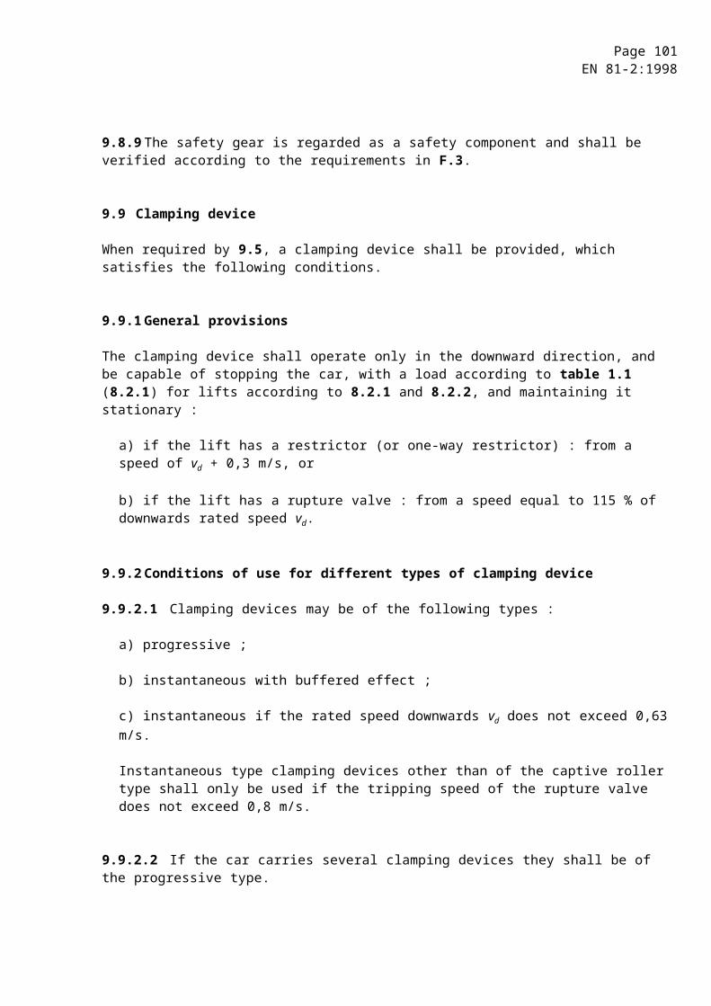
Page 101EN 81-2:1998
b) or safety circuits satisfying 14.1.2.3, consisting of one or a combination of the following :
1) either one or more safety contacts satisfying 14.1.2.2 not directly cutting the supply to the contactors referred to in 12.4 or their relay-contactors ;
2) contacts not satisfying the requirements of 14.1.2.2 ;
3) components in accordance with annex H.
14.1.2.1.2 (Kept free)
14.1.2.1.3 Apart from exceptions permitted in this standard (see 14.2.1.2, 14.2.1.4 and 14.2.1.5), no electric equipment shall be connected in parallel with an electric safety device.
Connections to different points of the electric safety chain are only permitted for gathering information. The devices used for that purpose shall fulfil the requirements for safety circuits according to 14.1.2.3.
14.1.2.1.4 The effects of internal or external induction or capacity shall not cause failure of electric safety devices.
14.1.2.1.5 An output signal emanating from an electric safety device shall not be altered by an extraneous signal emanating from another electric device placed further down the same circuit, which would cause a dangerous condition to result.
14.1.2.1.6 In safety circuits comprising two or more parallel channels, all information other than that required for parity checks shall be taken from one channel only.
14.1.2.1.7 Circuits which record or delay signals shall not, even in event of fault, prevent or appreciably delay the stopping of the machine through the functioning of an electric safety device, i.e. the stopping shall occur in the shortest time compatible with the system.
14.1.2.1.8 The construction and arrangement of the internal power supply units shall be such as to prevent the appearance of false signals at outputs of electric safety devices due to the effects of switching.
14.1.2.2 Safety contacts
14.1.2.2.1 The operation of a safety contact shall be by positive separation of the circuit-breaking devices. This separation shall occur even if the contacts have welded together.
The design of a safety contact shall be such as to minimize the risk of a short-circuit resulting from component failure.
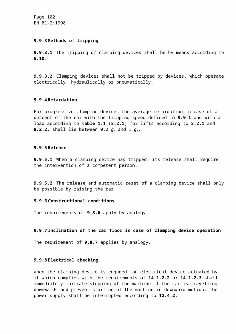
Page 102EN 81-2:1998
NOTE : Positive opening is achieved when all the contact-breaking elements are brought to their open position and when for a significant part of the travel there are no resilient members (e.g. springs) between the moving contacts and the part of the actuator to which the actuating force is applied.
14.1.2.2.2 The safety contacts shall be provided for a rated insulation voltage of 250 V if the enclosure provides a degree of protection of at least IP 4X, or 500 V if the degree of protection of the enclosure is less than IP 4X.
The safety contacts shall belong to the following categories as defined in EN 60947-5-1 :
a) AC-15 for safety contacts in A.C. circuits ;
b) DC-13 for safety contacts in D.C. circuits.
14.1.2.2.3 If the degree of protection is equal or less than IP4X, the clearances shall be at least 3 mm, the creepage distances at least 4 mm and the distances for breaking contacts at least 4 mm after separation. If the protection is better than IP4X the creepage distance can be reduced to 3 mm.
14.1.2.2.4 In the case of multiple breaks, the distance after separation between the contacts shall be at least 2 mm.
14.1.2.2.5 Abrasion of conductive material shall not lead to short circuiting of contacts.
14.1.2.3 Safety circuits
14.1.2.3.1 Safety circuits shall comply with the requirements of 14.1.1 relative to the appearance of a fault.
14.1.2.3.2 Furthermore, as illustrated by figure 6 the following requirements shall apply :
14.1.2.3.2.1 If one fault combined with a second fault can lead to a dangerous situation, the lift shall be stopped at the latest at the next operating sequence in which the first faulty element should participate.
All further operation of the lift shall be impossible as long as this fault persists.
The possibility of the second fault occurring after the first, and before the lift has been stopped by the sequence mentioned above is not considered.
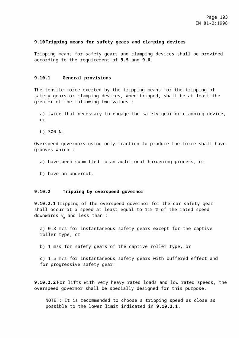
Page 103EN 81-2:1998
14.1.2.3.2.2 If two faults which by themselves do not lead to a dangerous situation, when combined with a third fault can lead to a dangerous situation, the lift shall be stopped at the latest at the next operating sequence in which one of the faulty elements should participate.
The possibility of the third fault leading to a dangerous situation before the lift has been stopped by the sequence mentioned above, is not considered.
14.1.2.3.2.3 If a combination of more then three faults is possible, then the safety circuit shall be designed with multiple channels and a monitoring circuit checking the equal status of the channels.
If a different status is detected the lift shall be stopped.
In case of two channels the function of the monitoring circuit shall be checked prior to a re-start of the lift at the latest, and in case of failure, re-starting shall not be possible.

Page 104EN 81-2:1998
NO
NO
NO
NO
NO
NO
Dangerous ?
Dangerous ?
Stop ?
Dangerous ?
Stop ?
Stop ?
Built-up according
14.1.2.3.2.3 ?
Fault 2
More than 3 faults
Not acceptable Acceptable
Fault 3
Fault 1
YES
YES
YES
YES
YES
YES
NO YES

Page 105EN 81-2:1998
Figure 6 : Diagram for assessing safety circuits
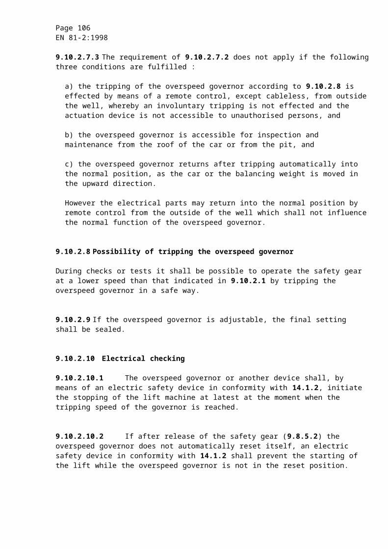
Page 106EN 81-2:1998
14.1.2.3.2.4 On restoration of the power supply after it has been disconnected, maintenance of the lift in the stopped position is not necessary, provided that during the next sequence stopping is reimposed in the cases covered by 14.1.2.3.2.1 up to 14.1.2.3.2.3.
14.1.2.3.2.5 In redundancy-type circuits measures shall be taken to limit as far as possible the risk of defects occurring simultaneously in more than one circuit arising from a single cause.
14.1.2.3.3 Safety circuits containing electronic components are regarded as safety components and shall be verified according to the requirements in F.6
14.1.2.4 Operation of electric safety devices
When operating to ensure safety, an electric safety device shall prevent the setting in motion of the machine or initiate immediately its stopping.
The electric safety devices shall act directly on the equipment controlling the supply to the machine in accordance with the requirements of 12.4.
If, because of the power to be transmitted, relay contactors are used to control the machine, these shall be considered as equipment directly controlling the supply to the machine for starting and stopping.
14.1.2.5 Actuation of electric safety devices
The components actuating the electric safety devices shall be built so that they are able to function properly under the mechanical stresses resulting from continuous normal operation.
If the devices for actuating electric safety devices are through the nature of their installation accessible to persons, they shall be so built that these electric safety devices cannot be rendered inoperative by simple means.
NOTE : A magnet or a bridge piece is not considered a simple means.
In the case of redundancy-type safety circuits, it shall be ensured by mechanical or geometric arrangements of the transmitter elements that a mechanical fault shall not cause loss of redundancy.
For transmitter elements of safety circuits, the requirements of F.6.3.1.1 apply.
14.2 Controls
14.2.1 Control of lift operations
Control shall be effected electrically.
Page 107EN 81-2:1998
14.2.1.1 Control of normal operation
This control shall be by the aid of buttons or similar devices, such as touch control, magnetic cards, etc.. These shall be placed in boxes, such that no live parts are accessible to the user.
14.2.1.2 Control of levelling, re-levelling and anti creeping with doors open
In the specific case referred to in 7.7.2.2 a) movement of the car with landing and car doors open is permitted for levelling, re-levelling and anti creeping on condition that :
a) the movement is limited to the unlocking zone (7.7.1) :
1) all movement of the car outside the unlocking zone shall be prevented by at least one switching device mounted in the bridge or shunt of the door and lock electric safety devices ;
2) this switching device shall :
- either be a safety contact in conformity with 14.1.2.2, or
- be connected in such a way as to satisfy the requirements for safety circuits in 14.1.2.3 ;
3) if the operation of the switches is dependent upon a device which is indirectly mechanically linked to the car, e.g. by rope, belt or chain, the breaking of or slack in the connecting link shall cause the machine to stop through the action of an electric safety device in conformity with 14.1.2 ;
4) during levelling operations, the means for making the electric safety devices of doors inoperative shall only function after the stopping signal for this landing has been given ;
b) the speed of re-levelling and electrical anti-creeping do not exceed 0,3 m/s.
14.2.1.3 Control of inspection operation
To facilitate inspection and maintenance, a readily accessible control station shall be provided on the car roof. This device shall be brought into operation by a switch (inspection operation switch) which shall satisfy the requirements for electric safety devices (14.1.2).
This switch, which shall be bi-stable, shall be protected against involuntary operation.
The following conditions shall be satisfied simultaneously :
a) engagement of the inspection operation shall neutralize :
1) the normal operation controls, including the operation of any automatic power operated doors ;
2) docking operation (14.2.1.4) ;
3) electrical anti-creep system (14.2.1.5 a) and b)).
Page 108EN 81-2:1998
The return to normal service of the lift shall only be effected by another operation of the inspection switch.
If the switching devices used for this neutralization are not safety contacts integral with the inspection switch mechanism, precautions shall be taken to prevent all involuntary movement of the car in the event of one of the faults listed in 14.1.1.1 appearing in the circuit.
b) the movement of the car shall be dependent on a constant pressure on a push-button protected against accidental operation and with the direction of movement clearly indicated ;
c) the control device shall also incorporate a stopping device in conformity with 14.2.2 ;
d) the car speed shall not exceed 0,63 m/s ;
e) the limits of normal car travel shall not be overrun ;
f) the operation of the lift shall remain dependent on the safety devices.
The control station may also incorporate special switches protected against accidental operation for controlling the mechanism of doors from the car roof.
14.2.1.4 Control of docking operation
In the specific case covered by 7.7.2.2 b), movement of the car is permitted with the landing and car doors open to allow loading or unloading of lifts, under the following conditions :
a) movement of the car shall only be possible in a zone not exceeding 1,65 m above the corresponding landing level ;
b) movement of the car shall be limited by a directional electric safety device in conformity with the requirements of 14.1.2 ;
c) the speed of movement shall not exceed 0,3 m/s ;
d) the landing door and the car door shall only be opened on the docking side ;
e) the zone of movement shall be clearly visible from the docking operation control position ;
f) the docking operation shall only become possible after operation of a key operated safety contact, the key of which can only be removed when in position to discontinue the docking operation. A key of this type shall be given only to a responsible person together with a written instruction drawing attention to the danger which may be involved in using this key ;
g) the engagement of the key operated safety contact :
1) shall neutralize the effects of the normal operation controls.
If the switching devices used are not safety contacts integral with the key operated contact mechanisms, precautions shall be taken to prevent all involuntary movement of the car in the event of one of the faults listed in 14.1.1.1 appearing in the circuit ;
Page 109EN 81-2:1998
2) shall only allow movement of the car by use of a constant pressure button. The direction of movement shall be clearly indicated ;
3) may render inoperative, by itself or through another electric switch in conformity with 14.1.2 :
- the electric safety device of the lock of the landing door concerned ;
- the electric safety device for proving closure of the landing door concerned ;
- the electric safety device for proving closure of the car door at the docking entrance ;
h) the effects of the docking operation shall be overridden by the engagement of the inspection operation ;
i) there shall be a stopping device in the car (14.2.2.1 e)).
14.2.1.5 Electrical anti-creep system
When required by 9.5, an electrical anti-creep system shall be provided, which satisfies the following conditions :
a) the machine shall be energized in the up direction independent of the position of the doors, when the car is in a zone which extends from maximum 0,12 m below the landing level to the lower end of the unlocking zone ;
b) the car shall be dispatched automatically to the lowest landing within 15 min after the last normal journey ;
c) lifts having a stopping device in the car (14.2.2.2 and 14.2.1.4 i)) shall be provided with an acoustic signal device on the car. This device shall operate when the stopping device is in the stop position. The power for this device shall be either from the emergency lighting supply called for in 8.17.4 or from an equivalent supply ;
d) Indications according to 15.2.5 and 15.4.6 shall be provided.
14.2.2 Stopping devices
14.2.2.1 A stopping device shall be provided for stopping, and maintaining the lift out of service, including the power operated doors :
a) in the lift pit (5.7.3.5 a)) ;
b) in the pulley room (6.4.5) ;
c) on the car roof (8.15), in an easily accessible position and no more than 1 m from the entry point for inspection or maintenance personnel. This device may be the one located next to the inspection operation control if this is not placed more than 1 m from the access point ;
d) at the inspection control device (14.2.1.3 c)) ;
e) in the car of lifts with docking operation (14.2.1.4 i)).
Page 110EN 81-2:1998
The stopping device shall be placed within 1 m of the entrance with docking operation and be clearly identified (15.2.3.1).
14.2.2.2 The stopping devices shall consist of electric safety devices in conformity with 14.1.2. They shall be bi-stable and such that a return to service cannot result from an involuntary action.
14.2.2.3 A stopping device in the car shall not be used except for cars with docking operation.
14.2.3 Emergency alarm device
14.2.3.1 In order to call for outside assistance, passengers shall have available in the car an easily recognizable and accessible device for this purpose.
14.2.3.2 The power for this device shall be either from the emergency lighting supply called for in 8.17.4 or from an equivalent supply.
NOTE : In the case of connection to a public telephone network, 14.2.3.2 does not apply.
14.2.3.3 This device shall allow a two-way voice communication allowing permanent contact with a rescue service. After initiation of the communication system no further action of the trapped person shall be necessary.
14.2.3.4 An intercom system, or similar device, powered by the emergency supply referred to in 8.17.4, shall be installed between inside the car and the machine room if a direct acoustic communication between the machine room and the well is not possible.
14.2.4 Priorities and signals
14.2.4.1 For lifts with manual doors, a device shall prevent the car leaving a landing for a period of at least 2 s after stopping.
14.2.4.2 A user entering the car shall have at least 2 s after the doors have closed, to actuate a control device before any external call buttons can become effective.
This requirement need not apply in the case of lifts operating on collective control.
14.2.4.3 In the case of collective control, an illuminated signal, which is clearly visible from the landing, shall indicate to the users waiting on this landing the direction of the next movement imposed on the car.
NOTE : For groups of lifts, position indicators on the landings are not recommended. However, it is recommended that the arrival of a car be preceded by an audible signal.
Page 111EN 81-2:1998
14.2.5 Load control
14.2.5.1 The lift shall be fitted with a device to prevent normal starting, excluding re-levelling, in the event of overload in the car.
14.2.5.2 The overload is considered to occur when the rated load is exceeded by 10 % with a minimum of 75 kg.
14.2.5.3 In the event of overload :
a) users shall be informed by an audible and/or a visible signal in the car ;
b) automatic power operated doors shall be brought into the fully open position ;
c) manually operated doors shall remain unlocked ;
d) any preliminary operation in accordance with 7.7.2.1 and 7.7.3.1 shall be nullified.
15 Notices, markings and operating instructions
15.1 General provisions
All labels, notices, markings and operating instructions shall be indelible, legible and readily understandable (if necessary aided by signs or symbols). They shall be untearable, of durable material, placed in a visible position, and written in the language of the country where the lift is installed (or, if necessary, in several languages).
15.2 Car
15.2.1 In the car the rated load of the lift in kilogrammes as well as the number of persons shall be displayed.
The number of persons shall be determined by reference to 8.2.3.
The notice shall be made as follows :
« .... kg ... PERS. »
The minimum height of the characters used for the notice shall be :
a) 10 mm for capital letters and numbers ;
b) 7 mm for small letters.
15.2.2 The vendor's name and the vendor's lift identification number shall be displayed in the car.

Page 112EN 81-2:1998
15.2.3 Other information in the car
15.2.3.1 The control device of the stop switch (where fitted) shall be red in colour and identified by the word “STOP”, so placed that there can be no risk of error as to the stop position.
The button(if any) of the alarm switch shall be yellow in colour and identified by the symbol :
The colours red and yellow shall not be used for other buttons. However, these colours may be used for illuminated 'call registered' signals.
15.2.3.2 The control devices shall be clearly identified by reference to their function ; for this purpose it is recommended to use :
a) for control buttons the markings -2, -1, 0, 1, 2, 3, etc. ;
b) for the door re-open button, where applicable, the indication :
15.2.4 Instructions to ensure safe usage of the lift shall be placed in the car whenever the need for these is apparent.
These shall at least indicate :
a) in the case of a lift with docking operation, instructions specific to this operation ;
b) for lifts with telephones or intercom system, the instructions for use, if not self-evident ;
c) that after using the lift, it is necessary to close manually operated doors and power operated doors where closing is carried out under the continuous control of the users.
15.2.5 In the case of a lift provided with an electrical anti-creep system and with manually operated doors, or with power operated doors where closing is carried out under the continuous control of the users, there shall be a notice in the car as follows :
«CLOSE DOORS»
The minimum height of the characters shall be 50 mm.
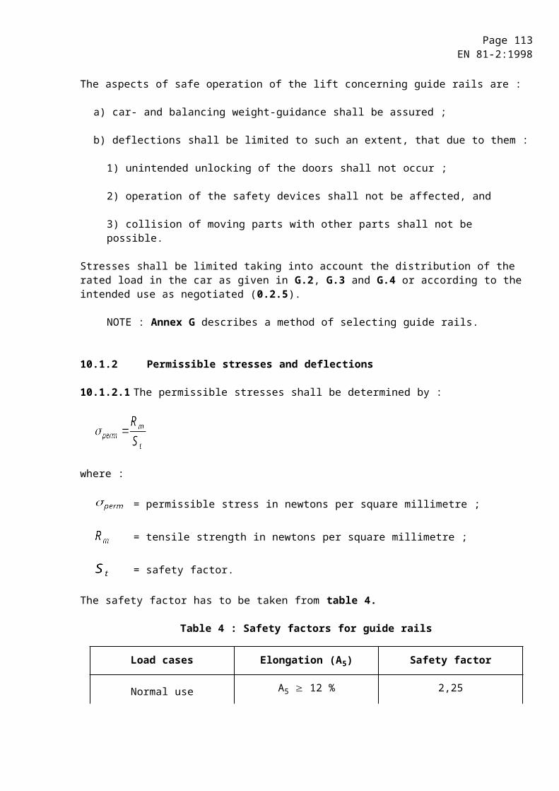
Page 113EN 81-2:1998
15.3 Car roof
On the car roof the following information shall be given :
a) the word «STOP» on or near the stopping device(s), so placed that there can be no risk of error as to the stop position ;
b) the words «NORMAL» and «INSPECTION» on or near the inspection operation switch ;
c) the direction of motion on or near the inspection buttons ;
d) warning sign or a notice at the balustrade.
15.4 Machine and pulley rooms
15.4.1 A notice bearing the following minimum inscription :
“Lift Machine - DangerAccess forbidden to unauthorized persons”
shall be fixed to the outside of doors or trap-doors giving access to the machines and pulleys.
In the case of trap-doors, a permanently visible notice shall indicate to those using the trap-door :
“Danger of falling - Reclose the trap-door”.
15.4.2 Notices shall be provided to permit easy identification of the main switch(es) and the light switch(es).
If, after release of a main switch, some parts remain live (interconnection between lifts, lighting, ...) notice (s) shall indicate this.
15.4.3 In the machine room, there shall be detailed instructions to be followed in the event of lift breakdown, particularly concerning the use of the device for manual or electrical emergency movement, and the unlocking key for landing doors.
15.4.4 On or near the stopping device in the pulley room there shall be the word “STOP” so placed that there can be no risk of error as to the stop position.
15.4.5 The maximum permissible load shall be indicated on the lifting beam or hooks (see 6.3.7).
15.4.6 In the case of a lift provided with an electrical anti-creep system there shall be an inscription on or near the main switch :
“Switch off only when the car is at the lowest landing”.

Page 114EN 81-2:1998
15.5 Well
15.5.1 Outside the well, near the inspection doors, there shall be a notice stating :
“Lift well - DangerAccess forbidden to unauthorized persons”
15.5.2 Landing doors with manual opening, if they can be confused with other adjacent doors, shall bear the inscription “LIFT”.
15.5.3 On goods passenger lifts a sign, which is visible from the landing loading area at all times, shall display the rated load.
15.6 Overspeed governor
On the overspeed governor a data plate shall be fixed indicating :
a) the name of the manufacturer of the overspeed governor ;
b) the type examination sign and its references ;
c) the actual tripping speed for which it has been adjusted.
15.7 Pit
On or near the stop switch in the pit there shall be the word “STOP”, so placed that there can be no risk of error as to the stop position.
15.8 Buffers
On the buffers, other than energy accumulation type buffers, there shall be a data plate showing :
a) the name of the manufacturer of the buffer ;
b) the type examination sign and its references.
15.9 Landing identification
Visible notices or signals shall permit persons in the car to know at which landing the lift has stopped.
15.10Electrical identification
Contactors, relays, fuses and connection strips for circuits coming into the control panels shall be marked in accordance with the wiring diagram. The necessary fuse specifications such as value and type shall be marked on the fuse or on or near the fuse holders.
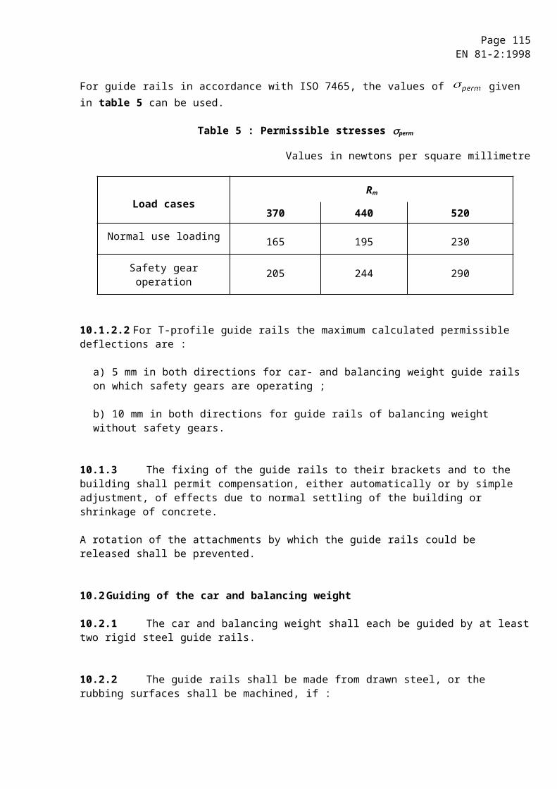
Page 115EN 81-2:1998
In the case of the use of multiple wire connectors, only the connector, and not the wires, needs to be marked.
15.11Unlocking key for landing doors
The unlocking key shall have a label attached drawing attention to the danger which may be involved in using this key and the need to make sure that the door is locked after it has been closed.
15.12Alarm device
The bell or device activated during a call for help from the car shall be clearly marked“Lift alarm”.
In the case of multiple lifts it shall be possible to identify the car from which the call is being made.
15.13Locking devices
On locking devices a data plate shall be fixed indicating :
a) the name of the manufacturer of the locking device ;
b) the type examination sign and its references.
15.14Safety gear
On safety gears a data plate shall be fixed indicating :
a) the name of the manufacturer of the safety gear ;
b) the type examination sign and its references.
15.15Emergency lowering valve
Near the manually operated valve for emergency downward movement there shall be a plate stating :
“Caution - Emergency lowering”.
15.16Hand pump
Near the hand pump for emergency upward movement there shall be a plate stating :
“Caution - Emergency lifting”.
Page 116EN 81-2:1998
15.17Groups of lifts
If parts of different lifts are present in one machine-, and/or pulley room each lift shall be identified with a number or letter consistently used for all parts (machine, controller, overspeed governor, switches, etc.).
To facilitate maintenance etc. on the car roof, in the pit or other places where necessary, the same identification symbol shall appear.
15.18Tank
On the tank the characteristics of the hydraulic fluid shall be indicated.
15.19Rupture valve/one-way restrictor
On rupture valve/one-way restrictor (12.5.6.6) a data plate shall be fixed indicating :
a) the name of the manufacturer of the rupture valve/one-way restrictor ;
b) the type examination sign and its references ;
c) the tripping flow for which it has been adjusted.
16 Examinations - Tests - Register - Maintenance
16.1 Examinations and tests
16.1.1 The technical dossier to be supplied if applying for preliminary authorization shall contain the necessary information to ascertain that the constituent parts are correctly designed and the proposed installation is in conformity with this standard.
This verification can only relate to items, or some of them, which form the subject of an examination or test prior to putting the lift into service.
NOTE : Annex C might serve as a basis for those who wish to carry out, or to have carried out, a study of an installation before putting it into effect.
16.1.2 Before putting into service, lifts shall be subject of examinations and tests in accordance with annex D.
NOTE : It may be required in the case of lifts which have not been subject to application for a preliminary authorization, to supply all or some of the technical information and calculations which appear in annex C.
Page 117EN 81-2:1998
16.1.3 A copy of each relevant type examination certificate shall be provided for :
a) locking devices ;
b) landing doors (i.e. fire test certificate);
c) safety gear ;
d) overspeed governors ;
e) rupture valve ;
f) energy dissipation type buffers, energy accumulation type buffers with buffered return movement and energy accumulation type buffers with non linear characteristics ;
g) safety circuits containing electronic components ;
h) one-way restrictor with mechanical moving parts.
16.2 Register
The basic characteristics of the lift shall be recorded in a register, or file, drawn up at the latest at the time the installation is put into service. This register or file shall comprise :
a) a technical section giving :
1) the date the lift was put into service ;
2) the basic characteristics of the lift ;
3) the characteristics of the ropes and/or chains ;
4) the characteristics of those parts for which verification of conformity is required (16.1.3) ;
5) the plans of installation in the building ;
6) electric schematic diagrams (using CENELEC symbols) ;
7) hydraulic circuit diagrams (using symbols from ISO 1219-1) ;
the hydraulic and electric diagrams may be limited to the circuits for the overall understanding of the safety considerations. The abbreviations used with the symbols shall be explained by means of a nomenclature ;
8) the full load pressure ;
9) the characteristics or type of hydraulic fluid.
b) a section intended to keep duplicate dated copies of examination and inspection reports, with observations.

Page 118EN 81-2:1998
This register or file shall be kept up-to-date in case of :
1) important modifications to the lift (annex E) ;
2) replacement of ropes or important parts ;
3) accidents.
NOTE : This register or file should be available to those in charge of the maintenance, and to the person or organization responsible for the periodical examinations and tests.
16.3 Installer information
The manufacturer/installer shall provide an instruction manual.
16.3.1 Normal use
The instruction manual shall give the necessary information about the normal use of the lift and rescue operation, especially about :
a) keeping the machine room door locked ;
b) safe loading and unloading ;
c) precaution to be taken in case of lifts with partially enclosed well (5.2.1.2 d)) ;
d) events needing the intervention of a competent person ;
e) keeping the documentation ;
f) the use of the emergency unlocking key ;
g) rescue operation.
16.3.2 Maintenance
The instruction manual shall inform about :
a) necessary maintenance of the lift and its accessories in order to keep it in working order (see 0.3.2) ;
b) instruction for safe maintenance.
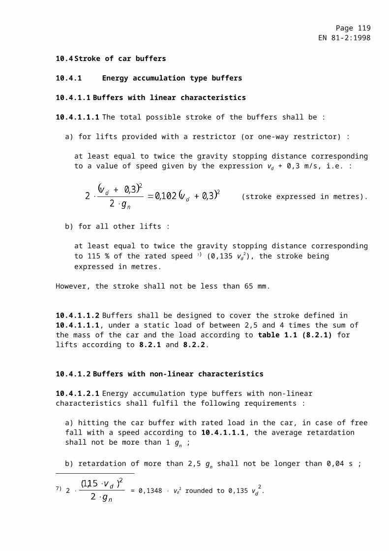
Page 119EN 81-2:1998
16.3.3 Examinations and tests
The instruction manual shall inform about the following :
16.3.3.1 Periodical examinations
Periodical examinations and tests on lifts should be carried out after they are put into service to verify that they are in good condition. These periodical examinations and tests should be carried out in accordance with annex E.
16.3.3.2 Examinations after important modifications or accidents
Examinations and tests should be carried out after important modifications or after an accident to ascertain that lifts continue to conform to this standard. These examinations and tests should be carried out in accordance with annex E.
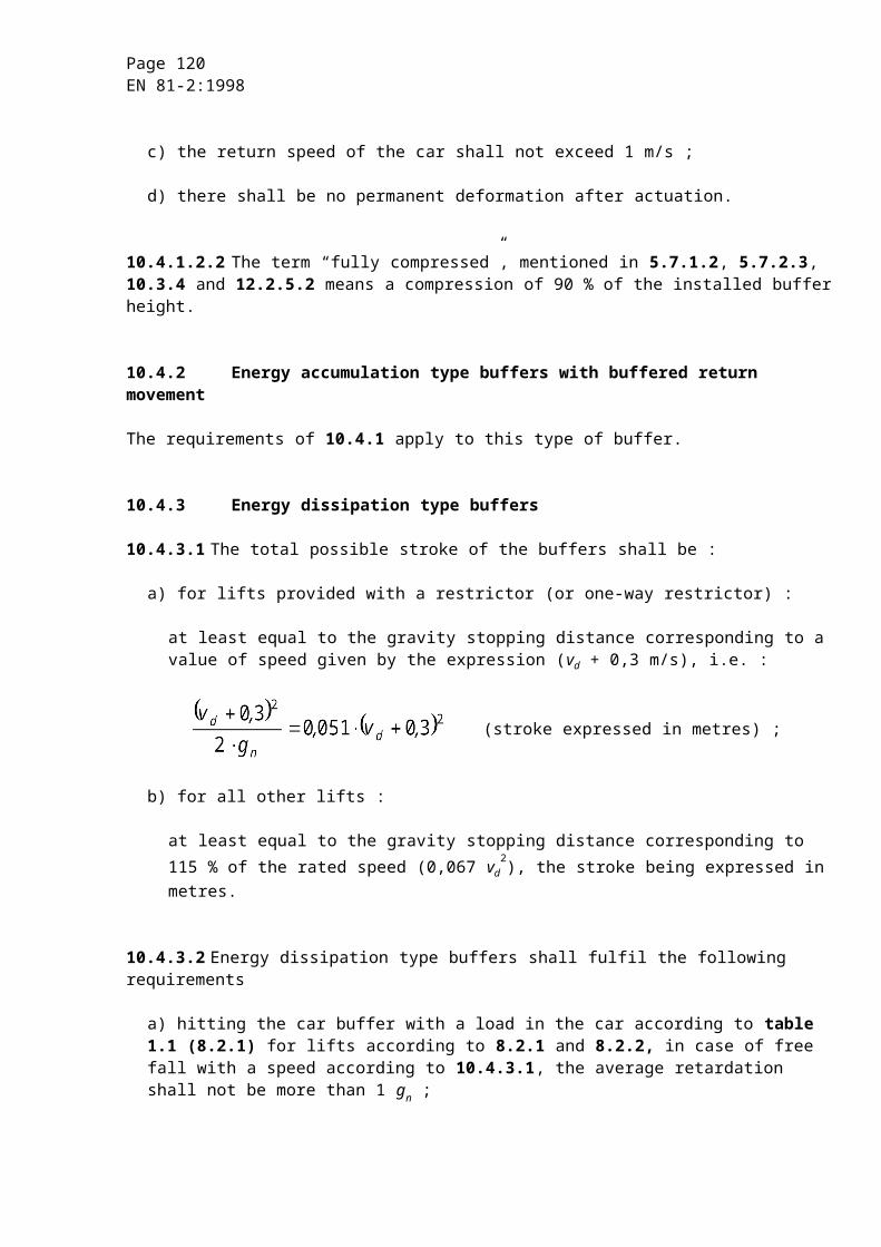
Page 120EN 81-2:1998
Annex A (normative)
List of the electric safety devices
Clause Devices checked5.2.2.2.2 Check on closed position of inspection and emergency doors and
inspection traps5.7.2.5 a) Stopping device in the pit6.4.5 Stopping device in the pulley room7.7.3.1 Check on locking of landing doors7.7.4.1 Check on closed position of landing doors7.7.6.2 Check on closed position of the panels without locks8.9.2 Check on closed position of car door8.12.4.2 Check on locking of the emergency trap and the emergency door in car8.15 b) Stopping device on the car roof9.3.3 Check on the abnormal relative extension of a rope or chain in case of
a two rope or two chain type suspension9.8.8 Check on the operation of safety gear9.10.2.10.1 Overspeed detection9.10.2.10.2 Check on the release of the overspeed governor9.10.2.10.3 Check on the tension in the overspeed governor rope9.10.4.4 Check on the tension in the safety rope10.4.3.3 Check on the return to normal extended position of buffers10.5.2.2 b) Check on the tension in the device for transmission of the car position
in case of direct acting lift (final limit switch)10.5.2.3 b) Check on the tension in the device for transmission of the car position
in case of indirect acting lift (final limit switch)10.5.3.1 Final limit switch 11.2.1 c) Check on locking of car door12.13 Check for slack rope or slack chain13.4.2 Control of main switch by means of circuit breaker contactor14.2.1.2 a) 2) Check on levelling, re-levelling and anti-creeping14.2.1.2 a) 3) Check on the tension in the device for transmission of the car position
(levelling, re-levelling and anti-creeping)14.2.1.3 c) Stopping device with inspection operation14.2.1.4 b) Limitation of movement of the car with docking operation14.2.1.4 i) Stopping device with docking operation

Page 121EN 81-2:1998
Annex B (normative)
Unlocking triangle
Dimensions in millimetres
Figure B. : Unlocking triangle
Page 122EN 81-2:1998
Annex C (informative)
Technical dossier
C.1 Introduction
The technical dossier to be submitted with the application for preliminary authorization should comprise all or part of the information and documents figuring in the following list.
C.2 General
- names and addresses of the installer, the owner and/or the user ;
- address of the installation premises ;
- type of equipment - rated load - rated speed - number of passengers ;
- travel of the lift, number of landings served ;
- mass of the car and of the balancing weight ;
- means of access to the machine room, and to the pulley room, if there is one (6.2).
C.3 Technical details and plans
Necessary plans and sections in order to understand the lift installation, including rooms for machines, pulleys and apparatus.
These plans do not have to give details of construction, but they should contain the necessary particulars to check conformity to this standard, and particularly the following :
- clearances at the top of the well and in the pit (5.7.1, 5.7.2) ;
- any accessible spaces which exist below the well (5.5) ;
- access to the pit (5.7.2.2) ;
- protection of jack(s), if required (12.2.4.1) ;
- guards between lifts if there are more than one in the same well (5.6) ;
- provisions for holes for fixings ;
- position and principal dimensions of the machine room with the layout of the machine and principle devices. Ventilation holes. Reaction loads on the building and at the bottom of the pit ;

Page 123EN 81-2:1998
- access to the machine room (6.3.3) ;
- position and principal dimensions of the pulley room, if any. Position and dimensions of pulleys ;
- position of other devices in the pulley room ;
- access to the pulley room (6.4.3) ;
- arrangement and principal dimensions of landing doors (7.3). It is not necessary to show all the doors if they are identical and if the distances between the landing door sills are indicated ;
- arrangement and dimensions of inspection doors and inspection traps and emergency doors (5.2.2) ;
- dimensions of the car and of its entrances (8.1, 8.2) ;
- distances from the sill and from the car door to the inner surface of the well wall (11.2.1) ;
- horizontal distance between the closed car and landing doors measured as indicated in 11.2.3 ;
- principal characteristics of the suspension -safety factor - ropes (number, diameter, composition and breaking load) - chains (type, composition, pitch, breaking load) ;
- declaration of the precautions provided :
- against free fall and descent with excessive speed ;
- against creeping ;
- functional drawing of the pawl device, if any (9.11) ;
- evaluation of the reaction force from a pawl device, if any, to the fixed stops ;
- principal characteristics of the overspeed governor rope and/or safety rope : diameter, composition, breaking load, safety factor ;
- dimensions and proof of the guide rails, condition and dimensions of the rubbing surfaces (drawn, milled, ground) ;
- dimensions and proof of energy accumulation type buffers with linear characteristics ;
- proof of the full load pressure ;
- proof of the jack and the piping according to annex K ;
- characteristics or type of the hydraulic fluid.
Page 124EN 81-2:1998
C.4 Electric schematic diagrams and hydraulic circuit diagram
Outline electric schematic diagrams of :
- the power circuits, and
- the circuits connected with electric safety devices.
These schematic diagrams should be clear and use CENELEC symbols.
Hydraulic circuit diagram.
This diagram shall be clear and use symbols of ISO 1219-1.
C.5 Verification of conformity
Copies of type examination certificates for safety components.
Copies of certificates for other components (ropes, chains, flexible hoses, explosion proof equipment, glass, etc.), where relevant.
Setting up certificate for the safety gear according to the instructions provided by the safety gear manufacturer and calculation of the compression of the springs in the case of progressive safety gear.
Setting up certificate for the rupture valve according to the instructions provided by the rupture valve manufacturer. Manufacturer' s adjustment diagrams should be provided.

Page 125EN 81-2:1998
Annex D (normative)
Examinations and tests before putting into service
Before the lift is put into service, the following examinations and tests shall be carried out :
D.1 Examinations
These examinations shall cover in particular the following points :
a) if there has been a preliminary authorization, comparison of the documents submitted on that occasion (annex C) with the installation as it has been installed ;
b) in all cases, verification that the requirements of this standard are fulfilled ;
c) visual examination of the application of the rules of good construction of the components for which this standard has no special requirements ;
d) comparison of the details given in the verification of conformity for the safety components, with the characteristics of the lift.
D.2 Tests and verifications
These tests and verifications shall cover the following points :
a) locking devices (7.7) ;
b) electric safety devices (annex A) ;
c) suspension elements and their attachments :
it shall be verified that their characteristics are those indicated in the register or file (16.2 a)) ;
d) measurements of current or power and of speed (12.8) ;
e) electric wiring :
1) measurement of the insulation resistance of the different circuits (13.1.3). For this measurement all the electronic components are to be disconnected ;
2) verification of the electrical continuity of the connection between the earth terminal of the machine room and the different parts of the lift liable to be made live accidentally ;
f) final limit switch (10.5) ;
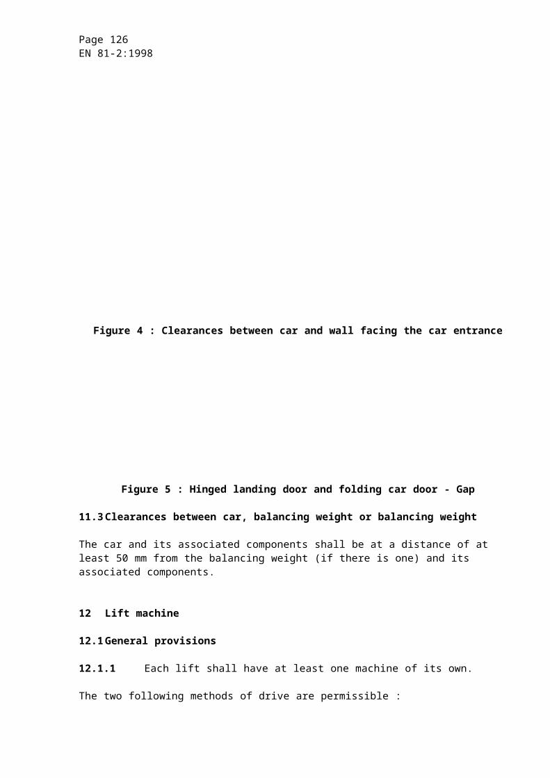
Page 126EN 81-2:1998
g) overspeed governor :
1) the tripping speed of the overspeed governor shall be checked in the direction corresponding to the descent of the car (9.10.2.1, 9.10.2.2) or the balancing weight (9.10.2.3) ;
2) the operation of the stopping control laid down in 9.10.2.10.1 and 9.10.2.10.2 shall be checked in both directions of movement ;
h) car safety gear (9.8) :
the energy, which the safety gear is capable of absorbing at the moment of engagement will have been verified in accordance with F.3. The aim of the test before putting into service is to check the correct mounting, correct setting and the soundness of the complete assembly, comprising car, safety gear, guide rails and their fixing to the building.
The test shall be made while the car is descending, with the required load uniformly distributed over the car area, keeping the downward valve(s) open until the ropes become slack, and under the following conditions :
1) instantaneous safety gear or instantaneous safety gear with buffered effect :
the car shall travel at rated speed and be loaded either :
a) with rated load when the rated load corresponds with table 1.1 (8.2.1), or
b) with 125 % of the rated load, except that the load shall not exceed the corresponding table 1.1 load when the rated load is smaller than the value given by table 1.1 (8.2.1) ;
2) progressive safety gear :
a) when the rated load corresponds with table 1.1 (8.2.1) the car shall be loaded with rated load, and travel at rated speed or lower ;
b) when the rated load is smaller than the value given by table 1.1 (8.2.1), the car shall be loaded with 125 % of the rated load, except that the load shall not exceed the corresponding table 1.1 load, and travel at rated speed or lower.
When the test is made with lower than rated speed, the manufacturer shall provide curves to illustrate the behaviour of the type tested progressive safety gear when dynamically tested with the suspensions attached.
After the test, it shall be ascertained that no deterioration, which could adversely affect the normal use of the lift has occurred. If necessary, friction components may be replaced. Visual check is considered to be sufficient ;
NOTE : In order to facilitate disengagement of the safety gear, it is recommended that the test be carried out opposite a door in order to be able to unload the car.
Page 127EN 81-2:1998
i) balancing weight safety gear (9.8) :
the energy, which the safety gear is capable of absorbing at the moment of engagement will have been verified in accordance with F.3. The aim of the test before putting into service is to check the correct mounting, correct setting and the soundness of the complete assembly, comprising balancing weight, safety gear, guide rails and their fixing to the building.
The test shall be made while the balancing weight is descending, under the following conditions :
1) instantaneous safety gear or instantaneous safety gear with buffered effect, tripped by overspeed governor or safety rope :
the test shall be made with empty car at rated speed ;
2) progressive safety gear :
the test shall be made with empty car at rated speed or lower.
When the test is made with lower than rated speed, the manufacturer shall provide curves to illustrate the behaviour of the type tested progressive safety gear under balancing weight application when dynamically tested with the suspensions attached.
After the test, it shall be ascertained that no deterioration, which could adversely affect the normal use of the lift has occurred. If necessary, friction components may be replaced. Visual check is considered to be sufficient ;
j) clamping device (9.9) :
the test shall be made while the car is travelling at normal speed downwards, with the load uniformly distributed, the contacts on the clamping device and on the tripping devices being short-circuited to avoid closing of the down direction valves, and under the following conditions :
1) instantaneous clamping device or instantaneous clamping device with buffered effect :
the car shall be loaded with 125 % of the rated load. When type-examined safety gears are used as clamping devices, however, the test may be made according to D.2 h) 1) ;
2) progressive clamping device :
a) when the rated load corresponds with table 1.1 (8.2.1) the car shall be loaded with 125 % of rated load ;
b) when the rated load is smaller than the value given by table 1.1 (8.2.1) the car shall be loaded with 125 % of rated load.
Additional to the test, it shall be shown by calculation that the requirements of 8.2.2.3 are satisfied.
After the test it shall be ascertained that no deterioration which could adversely affect the normal use of the lift has occurred. Visual check is considered to be sufficient ;
Page 128EN 81-2:1998
k) tripping of safety gear (car or balancing weight) by failure of the suspension gear (9.10.3) or by safety rope (9.10.4) :
check of the proper functioning ;
l) tripping of the car safety gear (or clamping device) by lever (9.10.5.2) :
visual examination of the engagement of the lever with all fixed stops and of the running clearance measured horizontally between the lever and all fixed stops during travel ;
m) pawl device (9.11) :
1) dynamic test :
the test shall be made while the car is travelling at normal speed downwards, with the load uniformly distributed, the contacts on the Pawl device and on the energy dissipation buffer (9.11.7), if any, being short-circuited to avoid closing of the down direction valves.
The car shall be loaded with 125 % of rated load and shall be stopped by the pawl device at each landing.
After the test it shall be ascertained that no deterioration which could adversely affect the normal use of the lift has occurred. Visual check is considered to be sufficient ;
2) visual examination of the engagement of the pawl(s) with all supports, and of the running clearance measured horizontally between the pawl(s) and all supports during travel ;
3) verification of the stroke of the buffers ;
n) buffers (10.3 and 10.4) :
1) energy accumulation type buffers :
the test shall be carried out in the following manner : the car with its rated load shall be placed on the buffer(s), the ropes shall be made slack and it shall be checked that the compression corresponds to the figures given in the technical dossier according to C.3 and means to identify the buffers according to C5 ;
2) energy accumulation type buffers with buffered return movement and energy dissipation type buffers :
the test shall be made in the following manner : the car with its rated load shall be brought into contact with the buffers at the rated speed.
After the test, it shall be ascertained that no deterioration, which could adversely affect the normal use of the lift has occurred. A visual check is considered to be sufficient ;
o) limitation of the ram stroke (12.2.3) :
verification that the ram is stopped with buffered effect ;
Page 129EN 81-2:1998
p) full load pressure :
measurement of the full load pressure ;
q) pressure relief valve (12.5.3) :
check of the correct adjustment ;
r) rupture valve (12.5.5) :
a system test shall be carried out, with rated load uniformly distributed in the descending car at an overspeed (12.5.5.7) to operate the rupture valve. The correct adjustment of the tripping speed can be checked, for instance, by comparison with the manufacture's adjustment diagram (C.5).
For lifts with several interconnected rupture valves checking of the simultaneous closing by measuring the inclination of the car floor (12.5.5.4) ;
s) restrictor/one-way restrictor (12.5.6) :
check that maximum speed vmax does not exceed vd + 0,3 m/s :
- either by measuring, or
- by using the following formula :
where :
p = full load pressure in megapascals ;
pt = pressure measured during a downward journey with rated load in the car in megapascals ;
If necessary pressure losses and friction losses shall be taken into account.
vmax = maximum downward speed in the case of a rupture in the hydraulic system in metres per second ;
vt = speed measured during a downward journey with rated load in the car in metres per second ;
t) pressure test :
a pressure of 200 % full load pressure is applied to the hydraulic system between the non-return valve and the jack included. The system is then observed for evidence of pressure drop and leakage during a period of 5 min (taking into account the possible effects of temperature change in the hydraulic fluid).
Page 130EN 81-2:1998
After this test it shall be visually ascertained that the integrity of the hydraulic system is maintained ;
NOTE : This test shall be carried out after the test of the devices against free fall (9.5).
u) creeping test :
it shall be checked that the car with the rated load, stopped at the highest level served does not move by more than 10 mm downwards within 10 min (taking into account the possible effects of temperature change in the hydraulic fluid) ;
v) emergency operation downwards (12.9.1.5) (in the case of indirect acting lifts) :
hand-lower the car onto a prop (or actuate the safety gear or clamping device) and check that slack rope or slack chain condition does not occur ;
w) motor run time limiter (12.12.1) :
check of the time adjustment (by simulating the running of the machine) ;
x) electric temperature detecting device (12.14) :
check of the temperature adjustment ;
y) electrical anti-creep system (14.2.1.5) :
functional test with rated load in the car ;
z) alarm device (14.2.3) :
functional test.
Page 131EN 81-2:1998
Annex E (informative)
Periodical examinations and tests, examinations and tests after an important modification or after an accident.
E.1 Periodical examinations and tests
Periodical examinations and tests shall not be more stringent than those required before the lift was the first time put into service.
These periodical tests should not, through their repetition, cause excessive wear or impose stresses likely to reduce the safety of the lift. This is the case in particular of the test on components such as the safety gear and the buffers. If tests on these components are made, they shall be carried out with empty car and at a reduced speed.
The person appointed to make the periodical test should assure himself that these components (which do not operate in normal service) are still in an operating condition.
A duplicate copy of the report should be attached to the register or file in the part covered by 16.2.
E.2 Examinations and tests after an important modification or after an accident
The important modifications and accidents shall be recorded in the technical part of the register or file covered in 16.2.
In particular, the following are considered as important modifications :
a) change :
- of the rated speed ;
- of the rated load ;
- of the mass of the car ;
- of the travel ;
b) change or replacement :
- of the type of locking devices (the replacement of a locking device by a device of the same type is not considered as an important modification) ;
- of the control system ;
- of guide rails or the type of guide rails ;
- of the type of door (or the addition of one or more landing or car doors) ;
- of the machine ;
Page 132EN 81-2:1998
- of the overspeed governor ;
- of the buffers ;
- of the safety gear ;
- of the clamping device ;
- of the pawl device ;
- of the jack ;
- of the pressure relief valve ;
- of the rupture valve ;
- of the restrictor/one-way restrictor.
For the tests after an important modification or after an accident the documents and the necessary information shall be submitted to the responsible person or organization.
Such person or organization will decide on the advisability of carrying out tests on the modified or replaced components.
These tests will, at the most, be those required for the original components before the lift was put into service.
Page 133EN 81-2:1998
Annex F (normative)
Safety components - Tests procedures for verification of conformity
F.0 Introduction
F.0.1 General provisions
F.0.1.1 For the purposes of this standard it is assumed that the laboratory undertakes both the testing and the certification as an approved body. An approved body may be that of a manufacturer operating an approved full quality assurance system. In certain cases the test laboratory and the body approved for the issue of type examination certificates may be separate. In these cases the administrative procedures may differ from those described in this annex.
F.0.1.2 The application for type examination shall be made by the manufacturer of the component or his authorized representative and shall be addressed to an approved test laboratory.
NOTE : At the request of the laboratory the necessary documents may be required in triplicate. The laboratory may likewise call for supplementary information, which might be necessary for the examination and tests.
F.0.1.3 The dispatch of samples for examination shall be made by agreement between the laboratory and the applicant.
F.0.1.4 The applicant may attend the tests.
F.0.1.5 If the laboratory entrusted with the complete examination of one of the components requiring the supply of a type examination certificate has not available appropriate means for certain tests or examinations, it may under its responsibility have these made by other laboratories.
Page 134EN 81-2:1998
F.0.1.6 The precision of the instruments shall allow, unless particularly specified, measurements to be made within the following tolerances :
a) 1 % masses, forces, distances, speeds ;
b) 2 % accelerations, retardations ;
c) 5 % voltages, currents ;
d) 5 °C temperatures ;
e) recording equipment shall be capable of detecting signals, which vary in time of 0,01 s ;
f) ± 2,5 % flow rate ;
g) ± 1 % pressure p £ 200 kPa ;
h) ± 5 % pressure p > 200 kPa.
F.0.2 Model form of type examination certificate
The examination certificate shall contain the following information.
Page 135EN 81-2:1998
MODEL TYPE-EXAMINATION CERTIFICATE
Name of the approved body : .....................................................................................................................................................................................................................................................................................................................................................................................................
Type-examination certificate : ....................................................................................................................................................................................................................................................................................................................................................................................................................................................................................................................................................
Type-examination N° : ..................................................................................................................
1 Category, type and make or trade name : .............................................................................
2 Manufacturer's name and address : ....................................................................................................................................................................................................................................................................................................................................................................................
3 Name and address of certificate holder : ............................................................................................................................................................................................................................................................................................................................................................................
4 Date of submission for type-examination : ............................................................................
5 Certificate issued on the basis of the following requirement : ..............................................................................................................................................................................................
6 Test laboratory : ....................................................................................................................
7 Date and number of laboratory report : .................................................................................
8 Date of type-examination : ....................................................................................................
9 The following documents, bearing the type-examination number shown above, are annexed to this certificate : ............................................................................................................................................................................................................................................
10 Any additional information : .................................................................................................................................................................................................................................................................................................................................................................................................
Place : ........................................................ ......................................................................(Date)
......................................................................(Signature)
Page 136EN 81-2:1998
F.1 Landing door locking devices
F.1.1 General provisions
F.1.1.1 Field of application
These procedures are applicable to locking devices for lift landing doors. It is understood that each component taking part in the locking of landing doors and in the checking of the locking forms part of the locking device.
F.1.1.2 Object and extent of the test
The locking device shall be submitted to a test procedure to verify that insofar as construction and operation are concerned, it conforms to the requirements imposed by this standard.
It shall be checked in particular that the mechanical and electrical components of the device are of adequate size and that in the course of time the device does not lose its effectiveness, particularly through wear.
If the locking device is needed to satisfy particular requirements (waterproof, dust proof or explosion proof construction) the applicant shall specify this and supplementary examinations and/or tests under appropriate criteria shall be made.
F.1.1.3 Documents to be submitted
The following documents shall be attached to the application for a type test :
F.1.1.3.1 Schematic arrangement drawing with description of operation
This drawing shall show clearly all the details relating to the operation and the safety of the locking device, including :
a) the operation of the device in normal service showing the effective engagement of the locking elements and the point at which the electrical safety device operates ;
b) the operation of the device for mechanical checking of the locking position if this device exists ;
c) the control and operation of the emergency unlocking device ;
d) the type (A.C. and/or D.C.) and the rated voltage and rated current.
F.1.1.3.2 Assembly drawing with key
This drawing shall show all parts, which are important to the operation of the locking device, in particular those required to conform to requirements of this standard. A key shall indicate the list of principal parts, the type of materials used, and the characteristics of the fixing elements.
Page 137EN 81-2:1998
F.1.1.4 Test samples
One door locking device shall be submitted to the laboratory.
If the test is carried out on a prototype, it shall be repeated later on a production model.
If the test of the locking device is only possible when the device is mounted in the corresponding door (for example, sliding doors with several panels or hinged doors with several panels) the device shall be mounted on a complete door in working order. However, the door dimensions may be reduced by comparison with a production model, on condition that this does not falsify the test results.
F.1.2 Examination and tests
F.1.2.1 Examination of operation
This examination has the aim of verifying that the mechanical and electrical components of the locking device are operating correctly with respect to safety, and in conformity with the requirements of this standard, and that the device is in conformity with the particulars provided in the application.
In particular it shall be verified :
a) that there is at least 7 mm engagement of the locking elements before the electric safety device operates. Examples are shown in 7.7.3.1.1.
b) that it is not possible from positions normally accessible to persons to operate the lift with a door open or unlocked, after one single action, not forming part of the normal operation (7.7.5.1).
F.1.2.2 Mechanical tests
These tests have the purpose of verifying the strength of the mechanical locking components and the electrical components.
The sample to the locking device in its normal operating position is controlled by the devices normally used to operate it.
The sample shall be lubricated in accordance with the requirements of the manufacturer of the locking device.
When there are several possible means of control and positions of operation, the endurance test shall be made in the arrangement which is regarded as the most unfavourable from the point of view of the forces on the components.
The number of complete cycles of operation and the travel of the locking components shall be registered by mechanical or electrical counters.
Page 138EN 81-2:1998
F.1.2.2.1 Endurance test
F.1.2.2.1.1 The locking device shall be submitted to 1 000 000 ( 1 %) complete cycles (one cycle comprises one forward and return movement over the full travel possible in both directions).
The driving of the device shall be smooth, without shocks, and at a rate of 60 ( 10 %) cycles per minute .
During the endurance test the electrical contact of the lock shall close a resistive circuit under the rated voltage and at a current value double that of the rated current.
F.1.2.2.1.2 If the locking device is provided with a mechanical checking device for the locking pin or the position of the locking element, this device shall be submitted to an endurance test of 100 000 ( 1 %) cycles.
The driving of the device shall be smooth, without shocks, and at a rate of 60 ( 10 %) cycles per minute.
F.1.2.2.2 Static test
For locking devices intended for hinged doors, a test shall be made consisting of the application over a total period of 300 s of a static force increasing progressively to a value of 3000 N.
This force shall be applied in the opening direction of the door and in a position corresponding as far as possible to that which may be applied when a user attempts to open the door. The force applied shall be 1000 N in the case of a locking device intended for sliding doors.
F.1.2.2.3 Dynamic test
The locking device, in the locked position, shall be submitted to a shock test in the opening direction of the door.
The shock shall correspond to the impact of a rigid mass of 4 kg falling in free fall from a height of 0,50 m.
F.1.2.3 Criteria for the mechanical tests
After the endurance test (F.1.2.2.1), the static test (F.1.2.2.2) and the dynamic test (F.1.2.2.3), there shall not be any wear, deformation or breakage, which could adversely affect safety.
F.1.2.4 Electrical test
F.1.2.4.1 Endurance test of contacts
This test is included in the endurance test laid down in F.1.2.2.1.1.

Page 139EN 81-2:1998
F.1.2.4.2 Test of ability to break circuit
This test is to be carried out after the endurance test. It shall check that the ability to break a live circuit is sufficient. This test shall be made in accordance with the procedure in EN 60947-4-1 and EN 60947-5-1, the values of current and rated voltage serving as a basis for the tests shall be those indicated by the manufacturer of the device.
If there is nothing specified, the rated values shall be as follows :
a) alternating current : 230 V, 2 A ;
b) direct current : 200 V, 2A.
In the absence of an indication to the contrary, the capacity to break circuit shall be examined for both A.C. and D.C. conditions.
The tests shall be carried out with the locking device in the working position. If several positions are possible, the test shall be made in the most unfavourable position.
The sample tested shall be provided with covers and electric wiring as used in normal service.
F.1.2.4.2.1 A.C. locking devices shall open and close an electric circuit under a voltage equal to 110 % of the rated voltage 50 times, at normal speed, and at intervals of 5 s to 10 s. The contact shall remain closed for at least 0,5 s.
The circuit shall comprise a choke and a resistance in series. Its power factor shall be 0,7 0,05 and the test current shall be 11 times the rated current indicated by the manufacturer of the device.
F.1.2.4.2.2 D.C. locking devices shall open and close an electric circuit under a voltage equal to 110 % of the rated voltage 20 times, at normal speed, and at intervals of 5 s to 10 s. The contact shall remain closed for at least 0,5 s.
The circuit shall comprise a choke and a resistance in series having values such that the current reaches 95 % of the steady-state value of the test current in 300 ms.
The test current shall be 110 % of the rated current indicated by the manufacturer of the device.
F.1.2.4.2.3 The tests are considered as satisfactory if no tracking or arcing is produced and if no deterioration occurs which could adversely affect safety.
F.1.2.4.3 Test for resistance to leakage currents
This test shall be made in accordance with the procedure in CENELEC HD 21.4 S2 (IEC 112). The electrodes shall be connected to a source providing an A.C. voltage which is sinusoidal at 175 V, 50 Hz.
AFNOR, 03/01/-1,
Page 140EN 81-2:1998
F.1.2.4.4 Examination of clearances and creepage distances
The clearances in air and creepage distances shall be in accordance with 14.1.2.2.3.
F.1.2.4.5 Examination of the requirements appropriate to safety contacts and their accessibility (14.1.2.2)
This examination shall be made taking account of the mounting position and the layout of the locking device, as appropriate.
F.1.3 Test particular to certain types of locking devices
F.1.3.1 Locking device for horizontally or vertically sliding doors with several panels
The devices providing direct mechanical linkage between panels according to 7.7.6.1 or indirect mechanical linkage according to 7.7.6.2 are considered as forming part of the locking device.
These devices shall be submitted in a reasonable manner to the tests mentioned in F.1.2. The number of cycles per minute in such endurance tests shall be suited to the dimensions of the construction.
F.1.3.2 Flap type locking device for hinged door
F.1.3.2.1 If this device is provided with an electric safety device required to check the possible deformation of the flap and if, after the static test envisaged in F.1.2.2.2 there are any doubts on the strength of the device, the load shall be increased progressively until the safety device begins to open. No component of the locking device or of the landing door shall be damaged or permanently deformed by the load applied.
F.1.3.2.2 If, after the static test, the dimensions and construction leave no doubt as to its strength, it is not necessary to proceed to the endurance test on the flap.
F.1.4 Type examination certificate
F.1.4.1 The certificate shall be drawn up in triplicate, i.e. two copies for the applicant, and one for the laboratory.

Page 141EN 81-2:1998
F.1.4.2 The certificate shall indicate the following :
a) information according to F.0.2 ;
b) type and application of locking device ;
c) the type (A.C. and/or D.C.) and values of rated voltage and rated current ;
d) in the case of flap type door locking devices : the necessary force to actuate the electric safety device for checking the elastic deformation of the flap.
F.2 Kept free
F.3 Safety gear
F.3.1 General provisions
The applicant shall state the range of use provided, i.e. :
- minimum and maximum masses ;
- maximum rated speed and maximum tripping speed.
Detailed information shall be provided on the materials used, the type of guide rails and their surface condition (drawn, milled, ground).
The following documents shall be attached to the application :
a) detailed and assembly drawings showing the construction, operation, materials used, the dimensions and tolerances on the construction components ;
b) in the case of progressive safety gear, also a load diagram relating to elastic parts.
F.3.2 Instantaneous safety gear
F.3.2.1 Test samples
Two gripping assemblies with wedges or clamps and two lengths of guide rail shall be submitted to the laboratory.
The arrangement and the fixing details for the samples shall be determined by the laboratory in accordance with the equipment that it uses.
If the same gripping assemblies can be used with different types of guide rail, a new test shall not be required if the thickness of the guide rails, the width of the grip needed for the safety gear and the surface state (drawn, milled, ground) are the same.
Page 142EN 81-2:1998
F.3.2.2 Test
F.3.2.2.1 Method of test
The test shall be made using a press or similar device, which moves without abrupt speed change. Measurements shall be made of :
a) the distance travelled as a function of the force ;
b) the deformation of the safety gear block as a function of the force or as a function of the distance travelled.
F.3.2.2.2 Test procedure
The guide rail shall be moved through the safety gear.
Reference marks shall be traced onto the blocks in order to be able to measure their deformation.
The distance travelled shall be recorded as a function of the force.
After the test :
a) the hardness of the block and the gripping element shall be compared with the original values quoted by the applicant. Other analyses may be carried out in special cases ;
b) if there is no fracture, deformations and other changes shall be examined (for example, cracks, deformations or wear of the jaws, appearance of the rubbed surfaces) ;
c) if necessary, photographs shall be taken of the block, the gripping elements and the guide rail for evidence of deformations or fractures.
F.3.2.3 Documents
F.3.2.3.1 Two charts shall be drawn up as follows :
a) the first shall show the distance travelled as a function of the force ;
b) the other shall show the deformation of the block. It shall be done in such a way that it can be related to the first chart.
F.3.2.3.2 The capacity of the safety gears shall be established by integration of the area of the distance-force chart.

Page 143EN 81-2:1998
The area of the chart to be taken into consideration shall be :
a) the total area if there is no permanent deformation ;
b) if permanent deformation or rupture has occurred, either :
1) the area up to the value at which the elastic limit has been reached, or
2) the area up to the value corresponding to the maximum force.
F.3.2.4 Determination of the permissible mass
F.3.2.4.1 Energy absorbed by the safety gear
A distance of free fall, calculated with reference to the maximum tripping speed of the overspeed governor fixed in 9.10.2.1 shall be adopted.
The distance of free fall in metres shall be taken as :
where :
v1 = tripping speed of overspeed governor in metres per second ;
gn = standard acceleration of free fall in metres per square second ;
0,10 m corresponds to the distance travelled during the response time ;
0,03 m corresponds to the travel during take-up of clearance between the gripping elements and the guide rails.
The total energy the safety gear is capable of absorbing :
2 K = (P + Q)1 gn h
from which :

Page 144EN 81-2:1998
where :
(P + Q)1 = permissible mass in kilogrammes ;
P = masses of the empty car and components supported by the car, i.e. part of the travelling cable, compensating ropes/chains (if any), etc. in kilogrammes ;
Q = rated load in kilogrammes ;
K, K1, K2 = energy absorbed by one safety gear block in joules (calculated in accordance with the chart).
F.3.2.4.2 Permissible mass
a) If the elastic limit has not been exceeded :
K is calculated by the integration of the area defined in F.3.2.3.2 a).
2 is taken as the safety coefficient. The permissible mass in kilogrammes will be :
b) If the elastic limit has been exceeded :
two calculations shall be made taking the one which is the more favourable to the applicant.
1) K1 is calculated by the integration of the area defined in F.3.2.3.2 b) 1) ;
2 is adopted as the safety coefficient and this will give the permissible mass in kilogrammes as :
2) K2 is calculated by the integration of the area defined in F.3.2.3.2 b) 2) ;
3,5 is adopted as the safety coefficient, and this will give the permissible mass in kilogrammes as :
F.3.2.5 Checking the deformation of the block and of the guide rail
If too great a deformation of the gripping elements in the block or the guide rail might cause difficulty in disengaging the safety gear, the permissible mass shall be reduced.
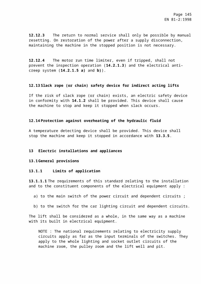
Page 145EN 81-2:1998
F.3.3 Progressive safety gear
F.3.3.1 Statement and test sample
F.3.3.1.1 The applicant shall state for what mass in kilogrammes and tripping speed in metres per second of the overspeed governor the test is to be carried out. If the safety gear has to be certified for various masses, he shall specify them and indicate in addition whether adjustment is by stages or continuous.
NOTE : The applicant should choose the suspended mass in kilogrammes by dividing the anticipated braking force in newtons by 16 to aim at an average retardation of 0,6 gn.
F.3.3.1.2 A complete safety gear assembly mounted on a cross-piece, with the dimensions fixed by the laboratory, together with the number of brake shoes necessary for all the tests shall be placed at the disposal of the laboratory. The number of sets of brake shoes necessary for all the tests shall be attached. For the type of guide rail used, the length specified by the laboratory shall also be supplied.
F.3.3.2 Test
F.3.3.2.1 Method of test
The test shall be carried out in free fall. Direct or indirect measurements shall be made of :
a) the total height of the fall ;
b) the braking distance on the guide rails ;
c) the sliding distance of the overspeed governor rope, or that of the device used in its place ;
d) the total travel of the elements forming the spring.
Measurements a) and b) shall be recorded as a function of the time.
The following shall be determined :
1) the average braking force ;
2) the greatest instantaneous braking force ;
3) the smallest instantaneous braking force.
F.3.3.2.2 Test procedure
F.3.3.2.2.1 Safety gear certified for a single mass
The laboratory shall carry out four tests with the mass (P + Q)1. Between each test the friction parts shall be allowed to return to their normal temperature.
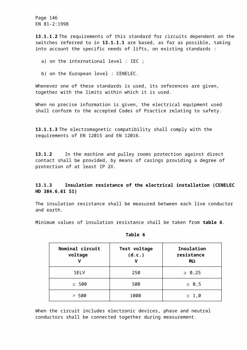
Page 146EN 81-2:1998
During the tests several identical sets of friction parts may be used.However, one set of parts shall be capable of :
a) three tests, if the rated speed does not exceed 4 m/s ;
b) two tests, if the rated speed exceeds 4 m/s.
The height of free fall shall be calculated to correspond to the maximum tripping speed of the overspeed governor for which the safety gear can be used.
The engagements of the safety gear shall be achieved by a means allowing the tripping speed to be fixed precisely.
NOTE : For example, a rope may be used, the slack of which should be carefully calculated, fixed to a sleeve which can slide with friction over a fixed smooth rope. The friction effort should be the same as the effort applied to the operating rope by the governor attached to this safety gear.
F.3.3.2.2.2 Safety gear certified for different masses
Adjustment in stages or continuous adjustment.
Two series of tests shall be carried out for :
a) the maximum, and
b) the minimum value applied for.
The applicant shall supply a formula, or a chart, showing the variation of the braking force as a function of a given parameter.
The laboratory shall verify by suitable means (in the absence of anything better, by a third series of tests for intermediary points) the validity of the supplied formula.
F.3.3.2.3 Determination of the braking force of the safety gear
F.3.3.2.3.1 Safety gear certified for a single mass
The braking force of which the safety gear is capable for the given adjustment and the type of guide rail is taken as equal to the average of the average braking forces determined during the tests. Each test shall be made on an unused section of guide rail.
Page 147EN 81-2:1998
A check shall be made that the average values determined during the tests lie within a range of 25 % in relation to the value of the braking force defined above.
NOTE : Tests have shown that the coefficient of friction could be considerably reduced if several successive tests were carried out on the same area of a machined guide rail. This is attributed to a modification in the surface condition during successive safety gear operations.
It is accepted that, on an installation, an inadvertent operation of the safety gear would have every chance of occurring at an unused spot.
It is necessary to consider that if, by chance, this were not the case, the braking force would have a lower value until an unused portion of guide rail surface was reached. Hence, greater sliding than normal.
This is a further reason for not permitting any adjustment causing too small a retardation at the beginning.
F.3.3.2.3.2 Safety gear certified for different masses
Adjustment in stages or continuous adjustment.
The braking force of which the safety gear is capable shall be calculated as laid down in F.3.3.2.3.1 for the maximum and minimum values applied for.
F.3.3.2.4 Checking after the tests
a) The hardness of the block and the gripping elements shall be compared with the original values submitted by the applicant. Other analyses may be made in special cases ;
b) the deformations and modifications (for example, cracks, deformations or wear of the gripping elements, appearance of the rubbing surfaces) shall be checked ;
c) if necessary, the safety gear assembly, the gripping elements and the guide rails shall be photographed in order to reveal deformations or fractures.
F.3.3.3 Calculation of the permissible mass
F.3.3.3.1 Safety gear certified for a single mass
The permissible mass shall be calculated using the following formula :
Page 148EN 81-2:1998
where :
(P + Q)1 = permissible mass in kilogrammes ;
P = masses of the empty car and components supported by the car, i.e. part of the travelling cable, compensating ropes/chains (if any), etc. in kilogrammes ;
Q = rated load in kilogrammes ;
Braking force = the force in newtons determined in accordance with F.3.3.2.3.
F.3.3.3.2 Safety gear certified for different masses
F.3.3.3.2.1 Adjustment in stages
The permissible mass shall be calculated for each adjustment as laid down in F.3.3.3.1.
F.3.3.3.2.2 Continuous adjustment
The permissible mass shall be calculated as laid down in F.3.3.3.1 for the maximum and minimum values applied for and in accordance with the formula supplied for the intermediate adjustments.
F.3.3.4 Possible modification to the adjustments
If, during the tests, the values found differ by more than 20 % from those expected by the applicant, other tests may be made with his agreement, after modification of the adjustments if necessary.
NOTE : If the braking force is clearly greater than that allowed for by the applicant, the mass used during the test would be clearly smaller than that which one would be led to authorize by calculation F.3.3.3.1 and consequently the test would not allow the conclusion that the safety gear is able to dissipate the required energy with the mass resulting from the calculation.
F.3.4 Comments
a) 1) When it is applied to a given lift, the mass stated by the installer shall not exceed the permissible mass for the safety gear (for instantaneous safety gear or instantaneous safety gear with buffered effect), and the adjustment considered ;
2) in the case of progressive safety gear, the mass stated may differ from the permissible mass defined in F.3.3.3 by 7,5 %. It is accepted in these conditions that the requirements of 9.8.4 are met on the installation, not withstanding the usual tolerances on the thickness of the guide rails, the surface conditions, etc. ;
b) to evaluate the validity of welded parts, reference shall be made to standards on this subject ;
Page 149EN 81-2:1998
c) a check shall be made that the possible travel of the gripping elements is sufficient under the most unfavourable conditions (accumulation of manufacturing tolerances) ;
d) the friction parts shall be suitably retained so that it can be certain that they will be in place at the moment of operation ;
e) In the case of a progressive type safety gear, it shall be checked that the travel of the components forming the spring is sufficient.
F.3.5 Type examination certificate
F.3.5.1 The certificate shall be drawn up in triplicate, i.e. two copies for the applicant, and one for the laboratory.
F.3.5.2 The certificate shall indicate the following :
a) information according to F.0.2 ;
b) type and application of safety gear ;
c) the limits of the permissible masses (see F.3.4 a)) ;
d) the tripping speed of the overspeed governor ;
e) the type of guide rail ;
f) the permissible thickness of the guide rail blade ;
g) the minimum width of the gripping areas ;
and, for progressive safety gear only :
h) the surface condition of the guide rails (drawn, milled, ground) ;
i) the state of lubrication of the guide rails. If they are lubricated, the category and specification of the lubricant.
F.4 Overspeed governors
F.4.1 General provisions
The applicant shall indicate the following to the laboratory :
a) the type (or the types) of safety gear which will be operated by the governor ;
b) the maximum and minimum rated speeds of lifts for which the governor may be used ;
c) the anticipated value of the tensile force produced in the rope by the overspeed governor when tripped.
Page 150EN 81-2:1998
The following documents are to be attached to the application :
detailed and assembly drawings showing the construction, operation, materials used, the dimensions and tolerances on the construction components.
F.4.2 Check on the characteristics of the governor
F.4.2.1 Test samples
The following shall be submitted to the laboratory :
a) one overspeed governor ;
b) one rope of the type used for the overspeed governor and in the normal condition in which it should be installed. The length to be supplied is fixed by the laboratory ;
c) a tensioning pulley assembly of the type used for the overspeed governor.
F.4.2.2 Test
F.4.2.2.1 Method of test
The following shall be checked :
a) the speed of tripping ;
b) the operation of the electric safety device called for in 9.10.2.10.1 causing the machine to stop, if this device is mounted on the overspeed governor ;
c) the operation of the electric safety device called for in 9.10.2.10.2 preventing all movement of the lift when the overspeed governor is tripped ;
d) the tensile force produced in the rope by the overspeed governor when tripped.
F.4.2.2.2 Test procedure
At least 20 tests shall be made in the speed range for tripping corresponding to the range of rated speeds of the lift, indicated in F.4.1 b).
NOTE 1 : The tests may be made by the laboratory in the component manufacturers works.
NOTE 2 : The majority of tests should be made at the extreme values of the range.
NOTE 3 : The acceleration to reach the tripping speed of the overspeed governor should be as low as possible, in order to eliminate the effects of inertia.
Page 151EN 81-2:1998
F.4.2.2.3 Interpretation of the test results
F.4.2.2.3.1 In the course of 20 tests the tripping speeds shall lie within the limits called for in 9.10.2.1.
NOTE : If the limits laid down are exceeded, an adjustment may be made by the manufacturer of the component and 20 new tests carried out.
F.4.2.2.3.2 In the course of the 20 tests the operation of the devices for which the test is required in F.4.2.2.1 b) and c) shall occur within the limits laid down in 9.10.2.10.1 and 9.10.2.10.2.
F.4.2.2.3.3 The tensile force in the rope produced by the overspeed governor when tripped shall be at least 300 N or any higher value which is specified by the applicant.
NOTE 1 : Unless otherwise requested by the manufacturer of the device and specified in the test report, the arc of engagement should be 180°.
NOTE 2 : In the case of a device, which operates by gripping the rope it should be checked that there is no permanent deformation of the rope.
F.4.3 Type examination certificate
F.4.3.1 The certificate shall be drawn up in triplicate, i.e. two copies for the applicant, and one for the laboratory.
F.4.3.2 The certificate shall indicate the following :
a) information according to F.0.2 ;
b) type and application of overspeed governor ;
c) the maximum and minimum rated speeds of the lift for which the overspeed governor may be used ;
d) the diameter of the rope to be used and its construction ;
e) in the case of an overspeed governor with traction pulley, the minimum tensioning force ;
f) the tensile force in the rope which can be produced by the overspeed governor when tripped.

Page 152EN 81-2:1998
F.5 Buffers
F.5.1 General provisions
The applicant shall state the range of use provided, i.e. maximum impact speed, minimum and maximum masses. The following are to be attached to the application :
a) detailed and assembly drawings showing the construction, operation, materials used, the dimensions and tolerances on the construction components.
In the case of hydraulic buffers, the graduation (openings for the passage of the liquid), in particular, shall be shown as a function of the stroke of the buffer ;
b) specifications for the liquid used.
F.5.2 Samples to be submitted
The following shall be submitted to the laboratory :
a) one buffer ;
b) in the case of hydraulic buffers, the necessary liquid sent separately.
F.5.3 Test
F.5.3.1 Energy accumulation type buffers with buffered return movement
F.5.3.1.1 Test procedure
F.5.3.1.1.1 The mass necessary to compress the spring completely shall be determined, for example, with the aid of weights loaded on to the buffer.
The buffer may only be used :
a) for rated speeds downwards :
1) for lifts provided with a restrictor (or a one-way restrictor) :
(see 10.4.1.1.1 a)),
where :
FL = total compression of the spring in metres ;
2) for all other lifts :
(see 10.4.1.1.1 a)) ;
Page 153EN 81-2:1998
b) for masses between :
1) maximum
2) minimum
where :
Cr = mass needed to compress the spring completely in kilogrammes.
F.5.3.1.1.2 The buffer shall be tested with the aid of weights corresponding to the maximum and minimum masses falling in free fall from a height above the buffer equal to 0,5 FL = 0,067 v2.
The speed shall be recorded from the moment of impact on the buffer and throughout the test. At no time shall the rising speed of the weights (during return) exceed 1 m/s.
F.5.3.1.2 Equipment to be used
The equipment shall satisfy to the following conditions :
F.5.3.1.2.1 Weights falling in free fall
The weights shall correspond, with the tolerances of F.0.1.6, to the minimum and maximum masses. They shall be guided vertically with the minimum of friction possible.
F.5.3.1.2.2 Recording equipment
The recording equipment shall be capable of detecting signals with the tolerance of F.0.1.6.
F.5.3.1.2.3 Measurement of speed
The speed shall be recorded with the tolerance of F.0.1.6.
F.5.3.1.3 Ambient temperature
The ambient temperature shall lie between + 15 °C and + 25 °C.
F.5.3.1.4 Mounting of the buffer
The buffer shall be placed and fixed in the same manner as in normal service.
Page 154EN 81-2:1998
F.5.3.1.5 Checking of the condition of the buffer after tests
After two tests with the maximum mass, no part of the buffer shall show any permanent deformation or be damaged so that its condition shall guarantee normal operation.
F.5.3.2 Energy dissipation buffers
F.5.3.2.1 Test procedure
The buffer shall be tested with the aid of weights, corresponding to the minimum and maximum masses, falling in free fall to reach at the moment of impact the maximum speed called for.
The speed shall be recorded at least from the moment of impact of the weights. The acceleration and the retardation shall be determined as a function of time throughout the movement of the weights.
NOTE : This procedure relates to hydraulic buffers ; for other types proceed by analogy.
F.5.3.2.2 Equipment to be used
The equipment shall satisfy to the following conditions :
F.5.3.2.2.1 Weights falling in free fall
The weights shall correspond, with the tolerances of F.0.1.6, to the maximum and minimum masses. They shall be guided vertically with the minimum of friction possible.
F.5.3.2.2.2 Recording equipment
The recording equipment shall be able to detect signals with the tolerances of F.0.1.6. The measuring chain, including the recording device for the recording of measured values as a function of time, shall be designed with a system frequency of at least 1000 Hz.
F.5.3.2.2.3 Measurement of speed
The speed shall be recorded at least from the moment of impact of the weights on the buffer or throughout the travel of the weights with the tolerances of F.0.1.6.
F.5.3.2.2.4 Measurement of the retardation
If there is a device for measuring retardation (see F.5.3.2.1), it shall be placed as near as possible to the axis of the buffer, and shall be capable of measurement with the tolerances of F.0.1.6.
Page 155EN 81-2:1998
F.5.3.2.2.5 Measurement of time
Time pulses of a duration of 0,01 s shall be recorded and measured with the tolerances of F.0.1.6.
F.5.3.2.3 Ambient temperature
The ambient temperature shall lie between + 15 °C and + 25 °C.
The temperature of the liquid shall be measured with the tolerances of F.0.1.6.
F.5.3.2.4 Mounting of the buffer
The buffer shall be placed and fixed in the same manner as in normal service.
F.5.3.2.5 Filling of the buffer
The buffer shall be filled up to the mark indicated following the instructions of the component manufacturer.
F.5.3.2.6 Checks
F.5.3.2.6.1 Checking of retardation
The height of free fall of the weights shall be chosen in such a way that the speed at the moment of impact corresponds to the maximum impact speed stipulated in the application.
The retardation shall conform to the requirements of 10.4.3.2 of this standard.
A first test shall be made with maximum mass with a check on the retardation.
A second test shall be made with minimum mass with a check on the retardation.
F.5.3.2.6.2 Checking of the return of the buffer to the normal position
After each test the buffer shall be held in the completely compressed position for 5 min. The buffer shall then be freed to permit its return to its normal extended position.
When the buffer is of a type with spring or gravity return, the position of complete return shall be reached in a maximum period of 120 s.
Before proceeding to another retardation test there shall be a delay of 30 min. to permit the liquid to return to the tank and for bubbles of air to escape.
Page 156EN 81-2:1998
F.5.3.2.6.3 Checking of the liquid losses
The level of liquid shall be checked after having made the two retardation tests required in F.5.3.2.6.1, and after an interval of 30 min. the level of liquid shall again be sufficient to ensure normal operation of the buffer.
F.5.3.2.6.4 Checking of the condition of the buffer after tests
After the two retardation tests required in F.5.3.2.6.1 no part of the buffer shall show any permanent deformation or be damaged so that its condition shall guarantee normal operation.
F.5.3.2.7 Procedure in the case of tests failing the requirements
When the test results are not satisfactory with the minimum and maximum masses appearing in the application, the laboratory may, in agreement with the applicant, establish the acceptable limits.
F.5.3.3 Buffers with non linear characteristics
F.5.3.3.1 Test procedure
F.5.3.3.1.1 The buffer shall be tested with the aid of masses falling in free fall from a height to reach at the moment of impact the maximum speed called for, but not less than 0,8 m/s.
The falling distance, the speed, the acceleration and retardation shall be recorded from the moment of release of the weight to the complete standstill.
F.5.3.3.1.2 The masses shall correspond to the maximum and minimum masses called for. They shall be guided vertically with a minimum of friction possible, so that at the moment of impact at least 0,9 gn are reached.
F.5.3.3.2 Equipment to be used
The equipment shall correspond to F.5.3.2.2.2, F.5.3.2.2.3, and F.5.3.2.2.4.
F.5.3.3.3 Ambient temperature
The ambient temperature shall lie between + 15 °C and + 25 °C.
F.5.3.3.4 Mounting of the buffer
The buffer shall be placed and fixed in the same manner as in normal service.
Page 157EN 81-2:1998
F.5.3.3.5 Number of tests
Three tests shall be made with :
a) the maximum mass ;
b) the minimum mass called for.
The time delay between two consecutive tests shall lie between 5 and 30 min.
With the three tests with maximum mass the value of reference of the buffer force at a stroke equal to 50 % of the real height of the buffer given by the applicant shall not vary by more than 5 %. With the tests with minimum mass this shall be observed in analogy.
F.5.3.3.6 Checks
F.5.3.3.6.1 Checking of retardation
The retardation 'a' shall conform to the following requirements :
a) the average retardation in case of free fall with a load in the car according to table 1.1 from a speed equal to 115 % of the rated speed shall not exceed 1 gn. The average retardation will be evaluated taking into account the time between the first two absolute minima of the retardation (see figure F.1) ;
b) peaks of retardation with more than 2,5 gn shall not be longer than 0,04 s.
t0 = moment of hitting the buffer (first absolute minimum) ;t1 = second absolute minimum.
Figure F.1 : Retardation graph
Page 158EN 81-2:1998
F.5.3.3.6.2 Checking of the condition of the buffer after tests
After the tests with the maximum mass no part of the buffer shall show any permanent deformation or be damaged so that its condition shall guarantee normal operation.
F.5.3.3.7 Procedure in the case of tests failing the requirements
When the test results are not satisfactory with the minimum and maximum masses appearing in the application, the laboratory may, in agreement with the applicant, establish the acceptable limits.
F.5.4 Type examination certificate
F.5.4.1 The certificate shall be drawn up in triplicate, i.e. two copies for the applicant, and one for the laboratory.
F.5.4.2 The certificate shall indicate the following :
a) information according to F.0.2 ;
b) type and application of buffer ;
c) the maximum impact speed ;
d) the maximum mass ;
e) the minimum mass ;
f) the specification of the liquid in the case of hydraulic buffers ;
g) environmental conditions for use (temperature, humidity, pollution, etc.) in case of buffers with non-linear characteristics.
F.6 Safety circuits containing electronic components
For safety circuits containing electronic components, laboratory tests are necessary because practical checks on site, by inspectors, are impossible.
In the following, mention is made to printed circuit board. If a safety circuit is not assembled in such a manner, then the equivalent assembly shall be assumed.

Page 159EN 81-2:1998
F.6.1 General provisions
The applicant shall indicate to the laboratory :
a) the identification on the board ;
b) working conditions ;
c) listing of used components ;
d) layout of the printed circuit board ;
e) layout of the hybrids and marks of the tracks used in safety circuits ;
f) function description ;
g) electrical data inclusive wiring diagram, if applicable, including input and output definitions of the board.
F.6.2 Test samples
There shall be submitted to the laboratory :
a) one printed circuit board ;
b) one printed circuit board bare ( without components ).
F.6.3 Tests
F.6.3.1 Mechanical tests
During the tests, the tested object (printed circuit) shall be kept under operation. During and after the tests, no unsafe operation and condition shall appear within the safety circuit.
F.6.3.1.1 Vibration
Transmitter elements of safety circuits shall withstand the requirements of :
a) EN 60068-2-6, Endurance by sweeping : Table C.2 :
20 sweep cycles in each axis, at amplitude 0,35 mm or 5 gn , and in the frequency range 10-55 Hz ;
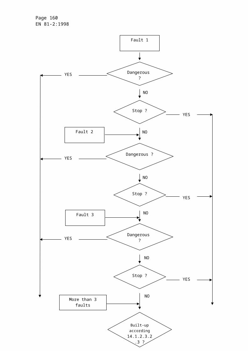
Page 160EN 81-2:1998
and also to :
b) EN 60068-2-27, Acceleration and duration of pulse : Table 1 :
the combination of :
- peak acceleration 294 m/s2 or 30 gn ;
- corresponding duration of pulse 11 ms, and
- corresponding velocity change 2,1 m/s half sine.
NOTE : Where shock absorbers for transmitter elements are fitted, they are considered as part of the transmitter elements.
After tests, clearances and creepage distances shall not become smaller than the minimum accepted.
F.6.3.1.2 Bumping (EN 60068-2-29)
Bumping tests are to simulate the cases when printed circuits fall, introducing the risk of rupture of components and unsafe situation.
Tests are divided into :
a) partial shockings ;
b) continuous shockings.
The tests object must satisfy the following minimum requirements :
F.6.3.1.2.1 Partial shocking
1) Shocking shapes : half-sinus ;
2) amplitude of acceleration : 15 g ;
3) duration of shock : 11 ms.
F.6.3.1.2.2 Continuous shocking
1) Amplitude of acceleration : 10 g ;
2) duration of shock : 16 ms ;
3) a) number of shocks : 1000 +/- 10 ;
b) shock frequency : 2/s.
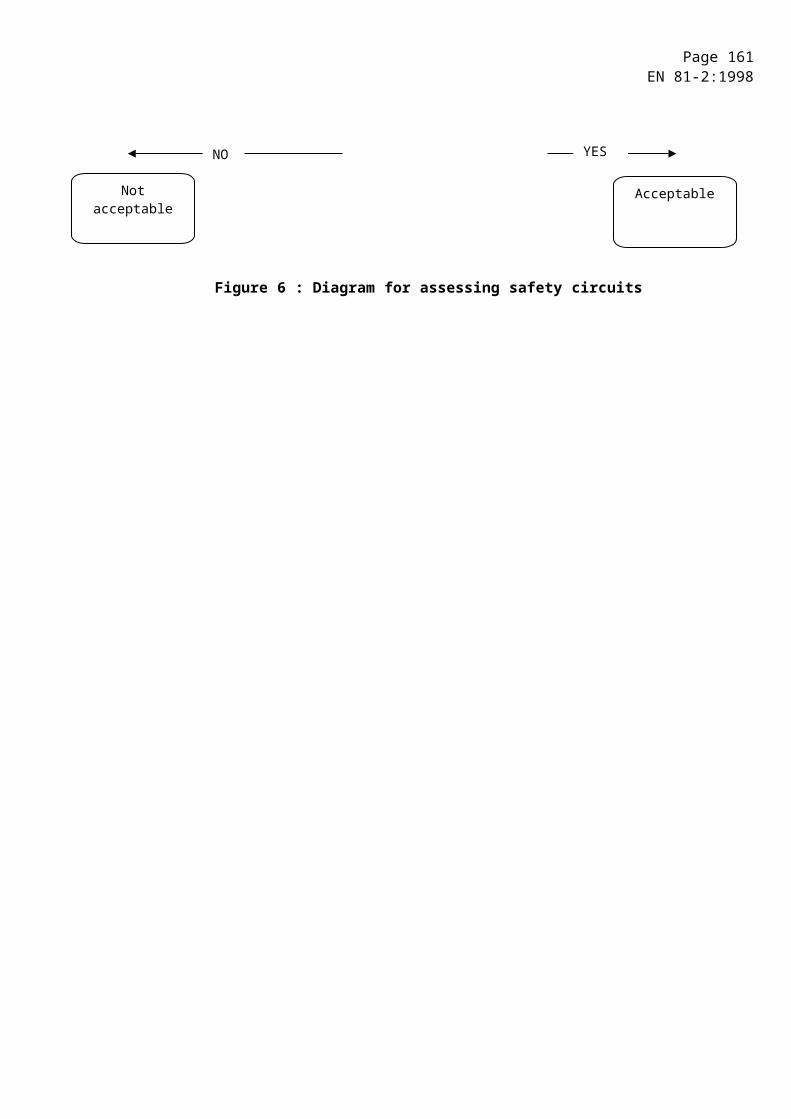
Page 161EN 81-2:1998
F.6.3.2 Temperature tests ( HD 323.2.14.S2 )
Operating ambient limits : 0 °C, + 65 °C (the ambient temperature is of the safety device).
Test conditions :
- the printed circuit board must be in operational position ;
- the printed circuit board must be supplied with normally rated voltage ;
- the safety device must operate during, and after the test. If the printed circuits board includes components other than safety circuits, they also must operate during the test (their failure is not considered) ;
- tests will be carried out for minimum and maximum temperature(0, + 65 °C). Tests will last a minimum of four hours ;
- if the printed circuit board is designed to operate within wider temperature limits, it must be tested for these values.
F.6.4 Type examination certificate
F.6.4.1 The certificate shall be drawn up in triplicate, i.e. two copies for the applicant and one copy for the laboratory.
F.6.4.2 The certificate shall indicate :
a) information according to F.0.2 ;
b) type and application in the circuitry ;
c) design for pollution degree according to IEC 60664-1 ;
d) operating voltages ;
e) distances between the safety circuits and the rest of the control circuits on the board.
NOTE : Other tests like humidity test, climatic shock test etc. are not subject for tests because of the normal environmental situation where lifts are operating.
F.6.5 Type examination certificate
F.6.5.1 The certificate shall be drawn up in triplicate, i.e. two copies for the applicant and one copy for the laboratory.
Page 162EN 81-2:1998
F.6.5.2 The certificate shall indicate :
a) information according to F.0.2 ;
b) type and application in the circuitry ;
c) designed for pollution degree according to IEC 664-1 ;
d) operating voltages ;
e) distances between the safety circuits and the rest of the control circuits on the board.
NOTE : Other tests like humidity test, climatic shock test, etc. are not subject for tests because of the normal environmental situation where lifts are operating.
F.7 Rupture valve/one-way restrictor
In the following the term “rupture valve” means “rupture valve/one-way restrictor with mechanical moving parts”.
F.7.1 General provisions
The applicant shall state :
a) the range of flow ;
b) the range of pressure ;
c) the range of viscosity ;
d) the range of ambient temperature ;
e) the method of mounting ;
of the rupture valve to be type examined.
The following are to be attached to the application :
- details and assembly drawings showing the construction, operation, adjustment, materials, dimensions and tolerances of the rupture valve and the construction components.
Page 163EN 81-2:1998
F.7.2 Samples to be submitted
There shall be submitted to the laboratory :
a) one rupture valve ;
b) a list of liquids which may be used together with the rupture valve or a sufficient amount of special liquid to be used ;
c) if necessary adaptation means to the test facilities of the laboratory.
F.7.3 Test
F.7.3.1 Test installation
The rupture valve, mounted in its intended method, shall be tested in a hydraulic system, where :
a) the required testing pressure is depending from a mass ;
b) the flow is controlled by adjustable valves ;
c) the pressure before 9) and behind the rupture valve can be recorded ;
d) installations to vary the ambient temperature of the rupture valve and the viscosity of the hydraulic liquid are provided.
The system shall allow to record the flow over the time. To determine the values of flow, the measurement of an other figure, i.e. the speed of the ram, from which the flow can be derived, is permitted.
F.7.3.2 Measuring instruments
The measuring instruments shall have an accuracy according to F.0.1.6 (see ISO 6403).
F.7.4 Test procedure
The test shall :
a) simulate a total piping failure occurring at a moment when the speed of the car is zero ;
b) evaluate the resistance of the rupture valve against pressure.
9) "Before the rupture valve" means between the cylinder and the rupture valve.
Page 164EN 81-2:1998
F.7.4.1 Simulation of a total piping failure
Simulating a total piping failure, the flow shall be initiated from a static situation by opening a valve under the condition that the static pressure before the rupture valve decrease to less than 10 %.
The following shall be taken into account :
a) tolerance of the closing value within the stated range of flow ;
b) tolerance of the closing value within the stated range of viscosity ;
c) tolerance of the closing value within the stated range of pressure ;
d) tolerance of the closing value within the stated range of ambient temperature.
That can be achieved by 2 test series :
a) with maximum pressure, maximum ambient temperature, minimum adjustable flow and minimum viscosity ;
b) with minimum pressure, minimum ambient temperature, maximum adjustable flow and maximum viscosity.
In each test series at least 10 tests shall be carried out, to evaluate the tolerances of operation of the rupture valve under these conditions.
During the tests the relation between :
- flow and time, and
- pressure before and behind the rupture valve and time
shall be recorded.
The typical characteristics of these curves are shown in the figure F.2.
F.7.4.2 Resistance against pressure
Showing the resistance of the rupture valve against pressure it shall be submitted to a pressure test with 5 times the maximum pressure over 2 min.
Page 165EN 81-2:1998
F.7.5 Interpretation of the tests
F.7.5.1 Closing operation
The rupture valve fulfils the requirements of the standard if the curves recorded according to F.7.4.1 show that :
a) the time to between rated flow (100 % flow) and the maximum flow Qmax does not exceed 0,16 s ;
b) the time td for the decrease of flow is :
where :
Qmax = maximum flow of the hydraulic fluid in litre per minute ;
td = braking time in seconds ;
A = area of jack, where pressure is acting in square centimetres ;
c) pressure of more than 3,5 Ps shall not be longer than 0,04 s ;
d) the rupture valve shall be tripped before the speed is equal to rated speed + 0,3 m/s.
F.7.5.2 Pressure resistance
The rupture valve fulfils the requirements of the standard if after the pressure test according to F.7.4.2 it shows no permanent damage.
F.7.5.3 Readjustment
If the limits of flow decrease or pressure peaks are exceeded, the manufacturer is allowed to modify the adjustment of the rupture valve. After that an other test serie may be carried out.
F.7.6 Type examination certificate
F.7.6.1 The certificate shall be drawn up in triplicate, i.e. two copies for the applicant and one copy for the laboratory.
Page 166EN 81-2:1998
F.7.6.2 The certificate shall indicate :
a) information according to F.0.2 ;
b) type and application of the rupture valve ;
c) the range of flow of the rupture valve ;
d) the range of pressure of the rupture valve ;
e) the range of viscosity of hydraulic fluids to be used ;
f) the range of ambient temperature of the rupture valve.
The certificate shall be accompanied with a graph according to figure F.2 showing the relationship between flow of hydraulic fluid and pressure from which Qmax and td can be obtained.
Page 167EN 81-2:1998
Pp pressure peak pressure after rupture valvePs pressure static hydraulic fluid flowt time pressure before rupture valve� the rupture valve must be tripped before the speed is equal to rated speed + 0,3 m/s
Figure F.2 : Hydraulic fluid flow through, pressure before and after the rupture valve
AFNOR, 03/01/-1,
Page 168EN 81-2:1998
Annex G (informative)
Proof of guide rails
G.1 General 10)
G.1.1 In order to fulfil the requirements of 10.1.1 guide rail calculations based on the following are accepted where no specific load distribution is intended.
G.1.1.1 The rated load - Q - is considered to be unevenly distributed over the car area, see G.2.2.
G.1.1.2 It is assumed that the safety devices operate simultaneously on the guide rails and that the braking force is equally distributed.
G.2 Loads and forces
G.2.1The acting point of the masses of the empty car and components supported by the car such as ram, part of travelling cable, compensating ropes/chains (if any) - P - shall be the centre of gravity of the mass of the car.
G.2.2 In the load cases “normal use” and “safety device operation” the rated load - Q - according to 8.2 shall be evenly distributed over those three quarters of the car area being in the most unfavourable position as depicted in the examples given in G.7.
However, if different load distribution conditions are intended after negotiations (0.2.5), the calculations shall be made on the basis of this conditions.
G.2.3The buckling force - Fk - of the car shall be evaluated by using the formula :
10) This annex is valid for both standards EN 81 part 1 and part 2.
Page 169EN 81-2:1998
where :
k1 = impact factor according to table G.2 ;
gn = standard acceleration of free fall (9,81 m/s2) ;
P = masses of the empty car and components supported by the car, i.e. part of the travelling cable, compensating ropes/chains (if any), etc. in kilogrammes ;
Q = rated load in kilogrammes ;
n = number of guide rails.
G.2.4The buckling force of the counterweight or balancing weight with safety gear - Fc - shall be evaluated by using the formula :
or
where :
k1 = impact factor according to table G.2 ;
gn = standard acceleration of free fall (9,81 m/s2) ;
P = masses of the empty car and components supported by the car, i.e. part of the travelling cable, compensating ropes/chains (if any), etc. in kilogrammes ;
Q = rated load in kilogrammes ;
q = balance factor indicating the amount of counterbalance of the rated load by the counterweight, or amount of counterbalance of the mass of the car by the balancing weight ;
n = number of guide rails.
G.2.5Whilst loading or unloading a car, a force on the sill -Fs- has to be assumed to act centrally on the sill of the car entrance. The amount of the force on the sill shall be :
Fs = 0,4 gn Q for lifts with rated loads less than 2500 kg in private premises, office buildings, hotels, hospitals etc. ;
Fs = 0,6 gn Q for lifts with rated loads of 2500 kg or more ;
Fs = 0,85 gn Q 11) for lifts with rated loads of 2500 kg or more in case of forklift truck loading.
11) 0,85 is based on the assumption of 0,6.Q and half of the weight of the forklift truck, which - due to experience (ANSI class C 2) - is not bigger than half the rated load (0,6 + 0,5 0,5) = 0,85.

Page 170EN 81-2:1998
Applying the force on the sill the car shall be regarded as empty. At cars with more than one entrance the force on the sill needs to be applied at the most unfavourable entrance only.
G.2.6The guiding forces of a counterweight or balancing weight - G - shall be evaluated taking into account :
- the acting point of the mass ;
- the suspension, and
- the forces due to compensating ropes/chains (if any), tensioned or not.
On a counterweight or balancing weight, centrally guided and suspended, an eccentricity of the acting point of the mass from the centre of gravity of the horizontal cross area of the counterweight or balancing weight of at least 5 % of the width and 10 % of the depth shall be taken into consideration.
G.2.7Forces per guide rail due to auxiliary equipment fixed to the guide rail - M - shall be considered, except for overspeed governors and their associated parts, switches or positioning equipment.
G.2.8Windloads - WL - shall be considered with lifts outside a building with incomplete well enclosure, and be determined by negotiation with the building designer (0.2.5).
G.3 Load cases
G.3.1The loads and forces and the load cases to be taken into consideration are shown in table G.1.
Table G.1 : Loads and forces to be taken into consideration in the different load cases
Load cases Loads and forces P Q G Fs Fk or Fc M WL
Normal running + + + - - + +
use loading + unloading + - - + - + +
Safetydevice
safety devicesor similar + + + - + + -
operation rupture valve + + - - - + -
G.3.2 In the documents intended for the first examination and test, it is sufficient to submit only the calculation of the most unfavourable load case.

Page 171EN 81-2:1998
G.4 Impact factors
G.4.1Safety device operation
The impact factor due to safety device operation k1 depends on the type of safety device.
G.4.2Car
In the load case “normal use, running”, the vertical moving masses of the car (P + Q) shall be multiplied by the impact factor k2 to take into consideration hard braking due to electric safety device actuation or by an accidental interruption of the power supply.
G.4.3Counterweight or balancing weight
The forces applied to the guide rails of the counterweight or balancing weight as specified in G.2.6 shall be multiplied with the impact factor k3 to take into account the possible counterweight or balancing weight bounce when the car is stopped with a retardation higher that 1 gn.
G.4.4Values of impact factors
The values of the impact factors are given in table G.2.
Table G.2 : Impact factors
Impact at Impact factor Value
Operation of instantaneous safety gear or clamping device, neither of the captiveroller type
5
Operation of instantaneous safety gear or clamping device, both of the captive roller type or pawl device with energy accumulation type bufferor energy accumulation type buffer
k1
3
Operation of progressive safety gear or progressive clamping deviceor pawl device with energy dissipation type buffer or energy dissipation type buffer
2
Rupture valve 2
Running k2 1,2
Auxiliary parts k3 (....) 1)
1) The value has to be determined by the manufacturer due to the actual installation.

Page 172EN 81-2:1998
G.5 Calculations
G.5.1Range of calculation
Guide rails shall be dimensioned taking into account bending stresses.
In cases where safety devices will act on guide rails, they shall be dimensioned taking into account bending and buckling stresses.
With hanging guide rails (fixed at the top of the well) instead of buckling, tensile stresses have to be taken into account.
G.5.2Bending stresses
G.5.2.1 Depending on :
- the suspension of the car, counterweight or balancing weight ;
- the position of the guide rails of the car, counterweight or balancing weight ;
- the load and its distribution in the car ;
the supporting forces - Fb - at the guide shoes create bending stresses in the guide rails.
G.5.2.2 Calculating the bending stresses in the different axis of the guide rail (figure G.1), it can be assumed that :
- the guide rail is a continuous beam with flexible fixing points at distances of the length l ;
- the resultant of forces causing bending stresses act in the middle between adjacent fixing points ;
- bending moments act on the neutral axis of the profile of the guide rail.
Evaluating the bending stress - m - from forces acting at right angles to the axis of the profile, the following formulae shall be used :
with :
Page 173EN 81-2:1998
where :
m = bending stress in newtons per square millimetre ;
Mm = bending moment in newtons millimetres ;
W = cross sectional area modulus in cubic millimetres ;
Fb = force applied to the guide rail by the guide shoes in the different load cases in newtons ;
= maximum distance between guide brackets in millimetres.
This is not valid for the load case «normal use, loading» provided the relative position of the guide shoes to the guide rail fixings has been taken into account.
G.5.2.3 Bending stresses in different axes shall be combined taking into account the guide rail profile.
If for Wx and Wy the usual values of tables (respectively Wxmin and Wymin) are used and therewith the permissible stresses are not exceeded, no further prove is necessary. Otherwise it has to be analysed at which outer edge of the guide rail profile the tensile stresses have their maximum.
G.5.2.4 If more than two guide rails are used, it is permitted to assume an equal distribution of the forces between the guide rails, provided their profiles are identical.
G.5.2.5 If more than one safety gear is used according to 9.8.2.2, it can be assumed that the whole braking force is equally distributed between the safety gears.
G.5.2.5.1 In the case of vertical multiplex safety gears acting on the same guide rail, it shall be assumed, that the braking force of a guide rail is acting on one point.
G.5.2.5.2 In the case of horizontal multiplex safety gears, the braking force in one of the guide rails shall be in accordance with G.2.3 or G.2.4.
G.5.3Buckling
Determining the buckling stresses the “omega” -method shall be used with the following formulae :
or
Page 174EN 81-2:1998
where :
k = buckling stress in newtons per square millimetre ;
Fk = buckling force on a guide rail of the car in newtons, see G.2.3 ;
Fc = buckling force on a guide rail of the counterweight or balancing weight in newtons, see G.2.4 ;
k3 = impact factor, see table G.2 ;
M = force in a guide rail due to auxiliary equipment in newtons ;
A = cross sectional area of a guide rail in millimetres.
= omega value.
The “omega”-values can be taken from the table G.3 and G.4 or can be evaluated by using the following polynomials with :
lik and lk = l
where :
= slenderness ;
lk = buckling length in millimetres ;
i = minimum radius of gyration in millimetres ;
l = maximum distance between guide brackets in millimetres.
For steel with tensile stress Rm = 370 N/mm2 :
20 £ £ 60 : = 0,00012920 · 1,89 + 1 ;
60 £ 85 : = 0,00004627 · 2,14 + 1 ;
85 £ 115 : = 0,00001711 · 2,35 + 1,04 ;
115 £ 250 : = 0,00016887 · 2,00.
For steel with tensile stress Rm = 520 N/ mm2 :
20 £ £ 50 : = 0,00008240 · 2,06 + 1,021 ;
50 £ 70 : = 0,00001895 · 2,41 + 1,05 ;
70 £ 89 : = 0,00002447 · 2,36 + 1,03 ;
89 £ 250 : = 0,00025330 · 2,00.
Page 175EN 81-2:1998
The determination of “omega”-values of steel with tensile stress Rm between 370 N/ mm2 and 520 N/ mm2 shall be carried out by using the following formula :
“Omega”-values of other tough metallic material have to be submitted by the manufacturer.
G.5.4Combination of bending and buckling stresses
The combined bending and buckling stresses shall be evaluated using the following formulae :
bending stresses m = x + y £ perm
bending and compression = m + £ perm
or
= m + £ perm
buckling and bending c = k + 0,9 m £ perm
where :
m = bending stress in newtons per square millimetre ;
x = bending stress in the X-axis in newtons per square millimetre ;
y = bending stress in the Y-axis in newtons per square millimetre ;
perm = permissible stress in newtons per square millimetre, see 10.1.2.1 ;
k = buckling stress in newtons per square millimetre ;
Fk = buckling force on a guide rail of the car in newtons, see G.2.3 ;
Fc = buckling force on a guide rail of the counterweight or balancing weight in newtons, see G.2.4 ;
k3 = impact factor see table G.2 ;
M = force in a guide rail due to auxiliary equipment in newtons ;
A = cross sectional area of a guide rail in square millimetre.
Page 176EN 81-2:1998
G.5.5Flange bending
Flange bending has to be taken into consideration.
For T-shaped guide rails, the following formula has to be used :
F = £ perm
where :
F = local flange bending stress in newtons per square millimetre ;
Fx = force exerted by a guide shoe to the flange in newtons ;
c = width of the connecting part of the foot to the blade in millimetres, see figure G.1 ;
perm = permissible stress in newtons per square millimetre.
Figure G. : Axis of the guide rail
Page 177EN 81-2:1998
Table G.3 : “Omega”-value related to for steel with tensile stress of 370 N/mm2
0 1 2 3 4 5 6 7 8 9
20 1,04 1,04 1,04 1,05 1,05 1,06 1,06 1,07 1,07 1,08 20
30 1,08 1,09 1,09 1,10 1,10 1,11 1,11 1,12 1,13 1,13 30
40 1,14 1,14 1,15 1,16 1,16 1,17 1,18 1,19 1,19 1,20 40
50 1,21 1,22 1,23 1,23 1,24 1,25 1,26 1,27 1,28 1,29 50
60 1,30 1,31 1,32 1,33 1,34 1,35 1,36 1,37 1,39 1,40 60
70 1,41 1,42 1,44 1,45 1,46 1,48 1,49 1,50 1,52 1,53 70
80 1,55 1,56 1,58 1,59 1,61 1,62 1,64 1,66 1,68 1,69 80
90 1,71 1,73 1,74 1,76 1,78 1,80 1,82 1,84 1,86 1,88 90
100 1,90 1,92 1,94 1,96 1,98 2,00 2,02 2,05 2,07 2,09 100
110 2,11 2,14 2,16 2,18 2,21 2,23 2,27 2,31 2,35 2,39 110
120 2,43 2,47 2,51 2,55 2,60 2,64 2,68 2,72 2,77 2,81 120
130 2,85 2,90 2,94 2,99 3,03 3,08 3,12 3,17 3,22 3,26 130
140 3,31 3,36 3,41 3,45 3,50 3,55 3,60 3,65 3,70 3,75 140
150 3,80 3,85 3,90 3,95 4,00 4,06 4,11 4,16 4,22 4,27 150
160 4,32 4,38 4,43 4,49 4,54 4,60 4,65 4,71 4,77 4,82 160
170 4,88 4,94 5,00 5,05 5,11 5,17 5,23 5,29 5,35 5,41 170
180 5,47 5,53 5,59 5,66 5,72 5,78 5,84 5,91 5,97 6,03 180
190 6,10 6,16 6,23 6,29 6,36 6,42 6,49 6,55 6,62 6,69 190
200 6,75 6,82 6,89 6,96 7,03 7,10 7,17 7,24 7,31 7,38 200
210 7,45 7,52 7,59 7,66 7,73 7,81 7,88 7,95 8,03 8,10 210
220 8,17 8,25 8,32 8,40 8,47 8,55 8,63 8,70 8,78 8,86 220
230 8,93 9,01 9,09 9,17 9,25 9,33 9,41 9,49 9,57 9,65 230
240 9,73 9,81 9,89 9,97 10,05 10,14 10,22 10,30 10,39 10,47 240
250 10,55

Page 178EN 81-2:1998
Table G.4 : “Omega”-value related to for steel with tensile stress of 520 N/mm2
0 1 2 3 4 5 6 7 8 9
20 1,06 1,06 1,07 1,07 1,08 1,08 1,09 1,09 1,10 1,11 20
30 1,11 1,12 1,12 1,13 1,14 1,15 1,15 1,16 1,17 1,18 30
40 1,19 1,19 1,20 1,21 1,22 1,23 1,24 1,25 1,26 1,27 40
50 1,28 1,30 1,31 1,32 1,33 1,35 1,36 1,37 1,39 1,40 50
60 1,41 1,43 1,44 1,46 1,48 1,49 1,51 1,53 1,54 1,56 60
70 1,58 1,60 1,62 1,64 1,66 1,68 1,70 1,72 1,74 1,77 70
80 1,79 1,81 1,83 1,86 1,88 1,91 1,93 1,95 1,98 2,01 80
90 2,05 2,10 2,10 2,19 2,24 2,29 2,33 2,38 2,43 2,48 90
100 2,53 2,58 2,64 2,69 2,74 2,79 2,85 2,90 2,95 3,01 100
110 3,06 3,12 3,18 3,23 3,29 3,35 3,41 3,47 3,53 3,59 110
120 3,65 3,71 3,77 3,83 3,89 3,96 4,02 4,09 4,15 4,22 120
130 4,28 4,35 4,41 4,48 4,55 4,62 4,69 4,75 4,82 4,89 130
140 4,96 5,04 5,11 5,18 5,25 5,33 5,40 5,47 5,55 5,62 140
150 5,70 5,78 5,85 5,93 6,01 6,09 6,16 6,24 6,32 6,40 150
160 6,48 6,57 6,65 6,73 6,81 6,90 6,98 7,06 7,15 7,23 160
170 7,32 7,41 7,49 7,58 7,67 7,76 7,85 7,94 8,03 8,12 170
180 8,21 8,30 8,39 8,48 8,58 8,67 8,76 8,86 8,95 9,05 180
190 9,14 9,24 9,34 9,44 9,53 9,63 9,73 9,83 9,93 10,03 190
200 10,13 10,23 10,34 10,44 10,54 10,65 10,75 10,85 10,96 11,06 200
210 11,17 11,28 11,38 11,49 11,60 11,71 11,82 11,93 12,04 12,15 210
220 12,26 12,37 12,48 12,60 12,71 12,82 12,94 13,05 13,17 13,28 220
230 13,40 13,52 13,63 13,75 13,87 13,99 14,11 14,23 14,35 14,47 230
240 14,59 14,71 14,83 14,96 15,08 15,20 15,33 15,45 15,58 15,71 240
250 15,83
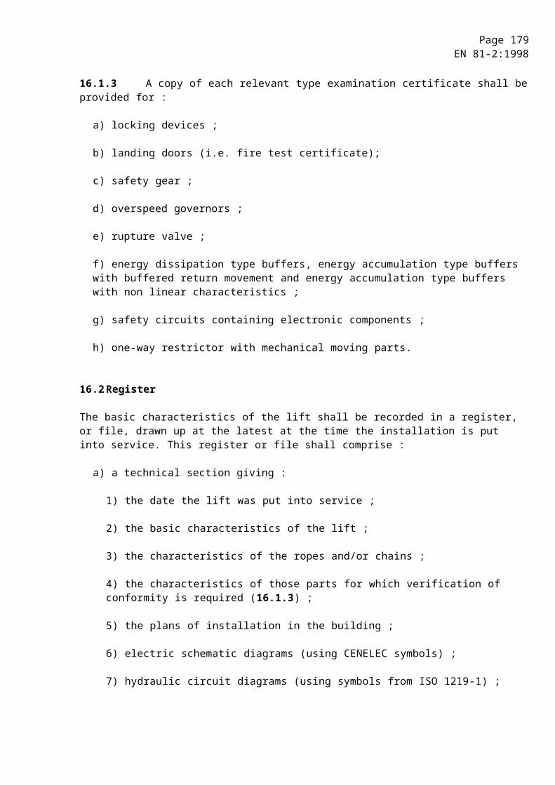
Page 179EN 81-2:1998
G.5.6Examples of guidance, suspension situations and load cases of the car and the relevant formulae are given in G.7.
G.5.7Deflections
The deflections shall be calculated by using the following formulae :
Y -Y guiding plane
X - X guiding plane
where :
x = deflection in the X-axis in millimetres ;
y = deflection in the Y-axis in millimetres ;
Fx = supporting force in the X-axis in newtons ;
Fy = supporting force in the Y-axis in newtons ;
l = maximum distance between guide brackets in millimetres ;
E = modulus of elasticity in newtons per square millimetre ;
Ix = second moment of area in the X-axis in fourth power millimetres ;
Iy = second moment of area in the Y-axis in fourth power millimetres.
G.6 Permissible deflections
The permissible deflections of T-profiled guide rails are stated in 10.1.2.2.
Deflections of guide rails other than T-profiles shall be limited such as to fulfil 10.1.1.
The combination of permissible deflections with the deflection of brackets, play in the guide shoes and straightness of the guide rails shall not affect the requirement of 10.1.1.
G.7 Examples of calculation method
The following examples are used to explain the calculation of the guide rails.
The following symbols will be used in a computer algorithm with a Cartesian coordinates system for all possible geometrical cases.

Page 180EN 81-2:1998
The following symbols are used for the dimensions in the lift :
DX = car dimension in X-direction, car depth ;
DY = car dimension in Y-direction, car width ;
xC, yc = position of the car centre (C) in relation to the guide rail cross coordinates ;
xS, yS = position of the suspension (S) in relation to the guide rail cross coordinates ;
xP, yP = position of the car mass (P) in relation to the guide rail cross coordinates ;
xCP, yCP = position of the car mass centre of gravity (P) in relation to the car centre (C) ;
S = car suspension ;
C = car centre ;
P = car bending mass - mass centre of gravity ;
Q = rated load - mass centre of gravity ;
= direction of loading ;
1,2,3,4 = centre of the car door 1, 2, 3 or 4 ;
xi, yi = position of the car door, i = 1, 2, 3 or 4 ;
n = number of guide rails ;
h = distance between car guide shoes ;
xQ, yQ = position of the rated load (Q) in relation to the guide rail cross coordinates ;
xCQ, yCQ = distance between the car centre (C) and the rated load (Q) in the X-direction,Y-direction.

Page 181EN 81-2:1998
G.7.1General configuration
G.7.1.1 Safety gear operation
G.7.1.1.1 Bending stress
a) Bending stress relative to the Y-axis of the guide rail due to guiding force :
, ,
b) Bending stress relative to the X-axis of the guide rail due to guiding force :
, ,

Page 182EN 81-2:1998
Load distributioncase 1 relative to the X-axis
x
y
S
-x
QC
P
xQ = xc +
yQ = yc
case 2 relative to the Y-axis
xQ = xc
yQ = yc +
G.7.1.1.2 Buckling
,
Page 183EN 81-2:1998
G.7.1.1.3 Combined stress 12)
£ perm
£ perm
£ perm
G.7.1.1.4 Flange bending 13)
£ perm
G.7.1.1.5 Deflections 14)
£ perm, £ perm
G.7.1.2 Normal use, running
G.7.1.2.1 Bending stress
a) Bending stress relative to the Y-axis of the guide rail due to guiding force :
, ,
b) Bending stress relative to the X-axis of the guide rail due to guiding force :
, ,
Load distribution : Case 1 relative to the X-axis (see G.7.1.1.1)
Case 2 relative to the Y-axis (see G.7.1.1.1)
12) These figures apply to both load distribution cases 1 and 2, see G.7.1.1.1.If perm < m, the figures for G.5.2.3 may be used in the interest of minimum guide rail dimensions.
13) These figures apply to both load distribution cases G.7.1.1.1.14) These figures apply to both load distribution cases G.7.1.1.1.
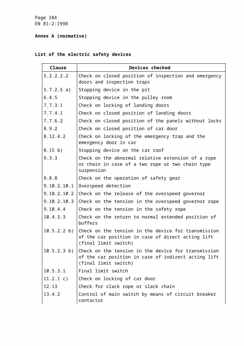
Page 184EN 81-2:1998
G.7.1.2.2 Buckling
In normal use, running, buckling does not arise.
G.7.1.2.3 Combined stress 15)
£ perm
£ perm
G.7.1.2.4 Flange bending 16)
£ perm
G.7.1.2.5 Deflections 17)
£ perm, £ perm
G.7.1.3 Normal use, loading
15) These figures apply to both load distribution cases G.7.1.2.1.If perm < m, the figures for G.5.2.3 may be used in the interest of minimum guide rail dimensions.
16) These figures apply to both load distribution cases G.7.1.1.1.17) These figures apply to both load distribution cases G.7.1.1.1.
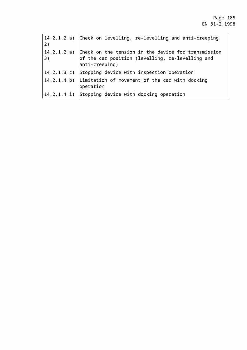
Page 185EN 81-2:1998
G.7.1.3.1 Bending stress
a) Bending stress relative to the Y-axis of the guide rail due to guiding force :
, ,
b) Bending stress relative to the X-axis of the guide rail due to guiding force :
, ,
G.7.1.3.2 Buckling
In normal use, loading, buckling does not arise.
G.7.1.3.3 Combined stress 18)
£ perm
£ perm
G.7.1.3.4 Flange bending
£ perm
G.7.1.3.5 Deflections
£ perm, £ perm
18) If perm < m, the figures for G.5.2.3 may be used in the interest of minimum guide rail dimensions.

Page 186EN 81-2:1998
G.7.2Centrally guided and suspended car
G.7.2.1 Safety gear operation
G.7.2.1.1 Bending stress
a) Bending stress relative to the Y-axis of the guide rail due to guiding force :
, ,
b) Bending stress relative to the X-axis of the guide rail due to guiding force :
, ,
Load distribution
case 1 relative to X-axis P and Q on the same side is the worst case, so Q in X-axis.
y
DY
D
C S QP
xQ
xPx1
YPx
x
yq = 0
case 2 relative to Y-axis
y
DY
D
C S
Q
P
xPx1
YPx
x
yQ xQ = 0
Page 187EN 81-2:1998
G.7.2.1.2 Buckling
,
G.7.2.1.3 Combined stress 19)
£ perm
£ perm
£ perm
G.7.2.1.4 Flange bending 20)
£ perm
G.7.2.1.5 Deflections 21)
£ perm, £ perm
G.7.2.2 Normal use, running
G.7.2.2.1 Bending stress
a) Bending stress relative to Y-axis of the guide rail due to guiding force :
b) Bending stress relative to X-axis of the guide rail due to guiding force :
, ,
Load distribution : Case 1 relative to the X-axis (see G.7.2.1.1)
Case 2 relative to the Y-axis (see G.7.2.1.1)
19) These figures apply to both distribution load cases G.7.2.1.1.20) These figures apply to both distribution load cases G.7.2.1.1.21) These figures apply to both distribution load cases G.7.2.1.1.

Page 188EN 81-2:1998
G.7.2.2.2 Buckling
In normal use, running, buckling does not arise.
G.7.2.2.3 Combined stress 22)
£ perm
£ perm
G.7.2.2.4 Flange bending 23)
£ perm
G.7.2.2.5 Deflections 24)
£ perm, £ perm
G.7.2.3 Normal use, loading
G.7.2.3.1 Bending stress
a) Bending stress relative to Y-axis of the guide rail due to guiding force :
, ,
b) Bending stress relative to X-axis of the guide rail due to guiding force:
, ,
G.7.2.3.2 Buckling
In normal use, loading, buckling does not arise.
22) These figures apply to both load distribution cases G.7.2.1.1.If perm < m, the figures for G.5.2.3 may be used in the interest of minimum guide rail dimensions.
23) These figures apply to both distribution load cases G.7.2.1.1.24).These figures apply to both distribution load cases G.7.2.1.1.
Page 189EN 81-2:1998
G.7.2.3.3 Combined stress 25)
£ perm
£ perm
G.7.2.3.4 Flange bending
£ perm
G.7.2.3.5 Deflections
£ perm, £ perm
G.7.3Eccentrically guided and suspended car
G.7.3.1 Safety gear operation
G.7.3.1.1 Bending stress
a) Bending stress relative to Y-axis of the guide rail due to guiding force :
, ,
b) Bending stress relative to X-axis of the guide rail due to guiding force :
, ,
25) If perm < m, the figures for G.5.2.3 may be used in the interest of minimum guide rail dimensions.

Page 190EN 81-2:1998
Load distribution
case 1 relative to X-axis
S C Q
x
x C
x S
P
x P
x Q
y
1xQ = xC +
yP = yC = yQ = yS = 0
case 2 relative to Y-axis
S
C
Q
x
x C
x Q
x S
y Q
x P
PD y
1
D xY
yQ =
xC = xQ
G.7.3.1.2 Buckling
,
Page 191EN 81-2:1998
G.7.3.1.3 Combined stress 26)
£ perm
£ perm
£ perm
G.7.3.1.4 Flange bending 27)
£ perm
G.7.3.1.5 Deflections 28)
£ perm, £ perm
G.7.3.2 Normal use, running
G.7.3.2.1 Bending stress
a) Bending stress relative to the Y-axis of the guide rail due to guiding force :
,
b) Bending stress relative to the X-axis of the guide rail due to guiding force:
, ,
Load distribution : Case 1 relative to the X-axis (see G.7.2.1.1)
Case 2 relative to the Y-axis (see G.7.2.1.1)
G.7.3.2.2 Buckling
In normal use, running, buckling does not arise.
26) These figures apply to both load distribution cases G.7.3.1.1.If perm < m, the figures for G.5.2.3 may be used in the interest of minimum guide rail dimensions.
27) These figures apply to both load distribution cases G.7.3.1.1.28) These figures apply to both load distribution cases G.7.3.1.1.
Page 192EN 81-2:1998
G.7.3.2.3 Combined stress 29)
£ perm
£ perm
G.7.3.2.4 Flange bending 30)
£ perm
G.7.3.2.5 Deflections 31)
£ perm, £ perm
G.7.3.3 Normal use, loading
S C x
xS
P
xP
1
y
Fs
x1
Dx
Sill
G.7.3.3.1 Bending stress
a) Bending stress relative to the Y-axis of the guide rail due to guiding force :
, ,
b) Bending stress relative to the X-axis of the guide rail due to guiding force :
Fy = 0
29) These figures apply to both load distribution cases G.7.3.1.1.If perm < m, the figures for G.5.2.3 may be used in the interest of minimum guide rail dimensions.
30) These figures apply to both load distribution cases G.7.3.1.1.31) These figures apply to both load distribution cases G.7.3.1.1.
Page 193EN 81-2:1998
G.7.3.3.2 Buckling
In normal use, loading, buckling does not arise.
G.7.3.3.3 Combined stress 32)
£ perm
£ perm
G.7.3.3.4 Flange bending
£ perm
G.7.3.3.5 Deflections
£ perm, y = 0
G.7.4Cantilevered guidance and suspension
G.7.4.1 Safety gear operation
G.7.4.1.1 Bending stress
a) Bending stress relative to the Y-axis of the guide rail due to guiding force :
, ,
b) Bending stress relative to the X-axis of the guide rail due to guiding force :
, ,
32) If perm < m, the figures for G.5.2.3 may be used in the interest of minimum guide rail dimensions.
Page 194EN 81-2:1998
Load distribution
case 1 relative to the X-axis
X
Dx/4
Dx
P Q
XP
c
S
XQ
Y
xP > 0 yP = 0
yQ = 0
case 2 relative to the Y-axis
Dx
Y
XP
c
Q
XQ
XP
SD y
D y /4
xP > 0 yP = 0
G.7.4.1.2 Buckling
,
Page 195EN 81-2:1998
G.7.4.1.3 Combined stress 33)
£ perm
£ perm
£ perm
G.7.4.1.4 Flange bending 34)
£ perm
G.7.4.1.5 Deflections 35)
£ perm, £ perm
G.7.4.2 Normal use, running
G.7.4.2.1 Bending stress
a) Bending stress relative to the Y-axis of the guide rail due to guiding force :
,
b) Bending stress relative to the X-axis of the guide rail due to guiding force :
, ,
Load distribution : Case 1 relative to the X-axis (see G.7.4.1.1)
Case 2 relative to the Y-axis (see G.7.4.1.1)
G.7.4.2.2 Buckling
In normal use, running, buckling does not arise.
33) These figures apply to both load distribution cases G.7.4.1.1.If perm < m, the figures for G.5.2.3 may be used in the interest of minimum guide rail dimensions.
34) These figures apply to both load distribution cases G.7.4.1.1.35) These figures apply to both load distribution cases G.7.4.1.1.
Page 196EN 81-2:1998
G.7.4.2.3 Combined stress 36)
£ perm
£ perm
G.7.4.2.4 Flange bending 37)
£ perm
G.7.4.2.5 Deflections 38)
£ perm, £ perm
36) These figures apply to both load distribution cases G.7.4.1.1.If perm < m, the figures for G.5.2.3 may be used in the interest of minimum guide rail dimensions.
37) These figures apply to both load distribution cases G.7.4.1.1.38) These figures apply to both load distribution cases G.7.4.1.1.
Page 197EN 81-2:1998
G.7.4.3 Normal use, loading
D x
Y
XP
c
X 1
X P
S
Fs
1
Dy
y1
xP > 0 yP = 0
x1 > 0
Dx
Y
XP
c
XP
S
Fs 2 Dyy2
x2
xP > 0 yP = 0 x2 > c+ Dx y2 0
G.7.4.3.1 Bending stress
a) Bending stress relative to the Y-axis of the guide rail due to guiding force :
, ,
b) Bending stress relative to the Y-axis of the guide rail due to guiding force :
, ,
Page 198EN 81-2:1998
G.7.4.3.2 Buckling
In normal use, loading, buckling does not arise.
G.7.4.3.3 Combined stress 39)
£ perm
£ perm
G.7.4.3.4 Flange bending
£ perm
G.7.4.3.5 Deflections
£ perm, £ perm
G.7.5Panoramic lift - General configuration
The following example is based on a panoramic car with eccentric guiding and suspension.
G.7.5.1 Safety gear operation
G.7.5.1.1 Bending stress
a) Bending stress relative to the Y-axis of the guide rail due to guiding force :
, ,
b) Bending stress relative to the X-axis of the guide rail due to guiding force :
, ,
39) If perm < m, the figures for G.5.2.3 may be used in the interest of minimum guide rail dimensions.
Page 199EN 81-2:1998
Load distribution
case1 relative to the X-axis
x
y
- y
C
S
P
- x
Q
xQ = The lever xq means the distance from the centre of gravity of the area marked, which is equal to 3/4rds of the total area covered by the car.
YQ = 0
case 2 relative to the Y-axis
x
y
- y
C
S
P
- x
Q
xQ =YQ =
The levers xo and yo mean the distances from the centre of gravity of the area marked which is equal to 3/4rds of the total area covered by the car
G.7.5.1.2 Buckling
,
Page 200EN 81-2:1998
G.7.5.1.3 Combined stress 40)
£ perm
£ perm
£ perm
G.7.5.1.4 Flange bending 41)
£ perm
G.7.5.1.5 Deflections 42)
£ perm, £ perm
G.7.5.2 Normal use, running
G.7.5.2.1 Bending stress
a) Bending stress relative to the Y-Axis of the guide rail due to guiding force :
,
b) Bending stress relative to the X-Axis of the guide rail due to guiding force :
, ,
Load distribution : Case 1 relative to the X-axis (see G.7.5.1.1)
Case 2 relative to the Y-axis (see G.7.5.1.1)
G.7.5.2.2 Buckling
In normal use, running, buckling does not arise.
40) These figures apply to both load distribution cases G.7.5.1.1.If perm < m, the figures for G.5.2.3 may be used in the interest of minimum guide rail dimensions.
41) These figures apply to both load distribution cases G.7.5.1.1.42) These figures apply to both load distribution cases G.7.5.1.1.

Page 201EN 81-2:1998
G.7.5.2.3 Combined stress 43)
£ perm
£ perm
G.7.5.2.4 Flange bending 44)
£ perm
G.7.5.2.5 Deflections 45)
£ perm, £ perm
G.7.5.3 Normal use, loading
xS
P
3
Fs
y
yi = o
43) These figures apply to both load distribution cases G.7.5.1.1.If perm < m, the figures for G.5.2.3 may be used in the interest of minimum guide rail dimensions.
44) These figures apply to both load distribution cases G.7.5.1.1.45) These figures apply to both load distribution cases G.7.5.1.1.
Page 202EN 81-2:1998
G.7.5.3.1 Bending stress
a) Bending stress relative to the Y-Axis of the guide rail due to guiding force :
, ,
b) Bending stress relative to the X-Axis of the guide rail due to guiding force :
Fy = 0
G.7.5.3.2 Buckling
In normal use, loading, buckling does not arise.
G.7.5.3.3 Combined stress
£ perm
£ perm
G.7.5.3.4 Flange bending 46))
£ perm
G.7.5.3.5 Deflections
£ perm, y = 0
46) ) If perm < m, the figures for G.5.2.3 may be used in the interest of minimum guide rail dimensions.
Page 203EN 81-2:1998
Annex H (normative)
Electronic components - Failure exclusion
The faults to be considered in the electric equipment of a lift are listed in 14.1.1.1. In 14.1.1 it is stated that certain faults can be excluded under specified conditions.
Failure exclusion shall only be considered provided that components are applied within their worst case limits of characteristics, value, temperature, humidity, voltage and vibrations.
The following table H.1 describes the conditions under which the faults envisaged in 14.1.1.1 e) can be excluded.
In the table :
- the “NO” in the cell means : failure not excluded, i.e. shall be considered ;
- the unmarked cell means : the identified fault type is not relevant.

Page 204EN 81-2:1998
Table H.1 : Exclusions of failures
Possible failure exclusion Component Open
circuitShort circuit
Change to higher value
Change to lower value
Change of function
Conditions Remarks
1 Passive components1.1 Resistor fixed NO (a) NO (a) (a) Only for film resistors with varnished
or sealed resistance film and axial connection according to applicable IEC standards, and for wire wound resistors if they are made of a single layer winding protected by enamel or sealed.
1.2 Resistor variable NO NO NO NO
1.3 Resistor, non linearNTC, PTC, VDR, IDR
NO NO NO NO
1.4 Capacitor NO NO NO NO
1.5 Inductive components- coil- choke
NO NO NO
2 Semiconductors2.1 Diode, LED NO NO NO Change of function
refers to a change in reverse current value.
2.2 Zener Diode NO NO NO NO Change to lower value refers to change in Zener voltage.Change of function refers to change in reverse current value.
“to be continued'
Page 205EN 81-2:1998
Table H.1 (continued)
Possible failure exclusion Component Open
circuitShort circuit
Change to higher value
Change to lower value
Change of function
Conditions Remarks
2 Semiconductors(Continued)
2.3 Thyristor, Triac, GTO NO NO NO Change of function refers to self triggering or latching of components.
2.4 Optocoupler NO (a) NO (a) Can be excluded under condition that the optocoupler is according to IEC 60747-5, and the isolation voltage is at least according to table below, IEC 60664-1, Table 1.
Open circuit means open circuit in one of the two basic components (LED and photo transistor).Short circuit means short circuit between them.
Voltage phase-to-earth derived from rated system voltage up to and including Vrms and d.c.
Preferred series of impulse withstand voltages in volts for installation
Category III50 800
100 1 500150 2 500300 4 000600 6 000
1 000 8 000“to be continued”

Page 206EN 81-2:1998
Table H.1 (continued)
Possible failure exclusion Component Open
circuitShort circuit
Change to higher value
Change to lower value
Change of function
Conditions Remarks
2 Semiconductors (continued)
2.5 Hybrid circuit NO NO NO NO NO
2.6 Integrated circuit NO NO NO NO NO Change in function to oscillation, “and” gates becoming “or” gates, etc...
3 Miscellaneous3.1 Connectors
TerminalsPlugs
NO (a) (a) The short circuits of connectors can be excluded if the minimum values are according to the tables (taken over from IEC 60664-1) with the conditions : - the pollution degree is 3 ; - the material group is III ; - inhomogeneous field .The column "printed wiring material" of table 4 is not used.These are absolute minimum values which can be found on the connected unit, not pitch dimension or theoretical values.If the protection of the connector is IP 5X or better, the creepage distances can be reduced to the clearance value, e.g. 3 mm for 250 Vrms.
3.2 Neon bulb NO NO“to be continued”

Page 207EN 81-2:1998
Table H.1 (continued)
Possible failure exclusion Component Open
circuitShort circuit
Change to higher value
Change to lower value
Change of function
Conditions Remarks
3 Miscellaneous (continued)
3.3 Transformer NO (a) (b) (b) (a) (b)Can be excluded under condition that isolation voltage between windings and core is in line with EN 60742, 17.2 and 17.3, and the working voltage is the highest possible voltage of table 6 between live and earth
Short-circuits include short-circuits of primary or secondary windings, or between primary and secondary coils.Change in value refers to change of ratio by partial short-circuit in a winding.
3.4 Fuse (a) (a) Can be excluded if the fuse is correctly rated, and constructed according to the applicable IEC standards.
Short circuit means short circuit of the blown fuse.
3.5 Relay NO (a)(b)
(a) Short-circuits between contacts, and between contacts and coil can be excluded if the relay fulfils the requirements of 13.2.2.3 (14.1.2.2.3).
(b) Welding of contacts can not be excluded.However, if the relay is constructed to have mechanically forced interlocked contacts, and made according to EN 60947-5-1, the assumptions of 13.2.1.3 apply.
“to be continued”
Page 208EN 81-2:1998
Table H.1 (continued)
Possible failure exclusion Component Open
circuitShort circuit
Change to higher value
Change to lower value
Change of function
Conditions Remarks
3 Miscellaneous (continued)
3.6 Printed circuit board (PCB)
NO (a) (a) The short circuit can be excluded provided :- the general specifications of PCB are in accordance with EN 62326-1 ;- the base material is in accordance to the specifications of EN 60249-2-3 and/or EN 60249-2-2 ;- the PCB is constructed according to the above requirements and the minimum values are according to the tables (taken over from IEC 60664-1) with the conditions : - the pollution degree is 3 ; - the material group is III ; - inhomogeneous field. The column "printed wiring material" of table 4 is not used.That means that the creepage distances are 4 mm and the clearances 3 mm for 250 Vrms. For other voltages refer to IEC 60664-1.If the protection of the PCB is IP 5X or better, or the material involved of higher quality, the creepage distances can be reduced to the clearance value, e.g. 3 mm for 250 Vrms. For multi-layer boards comprising at least 3 prepreg or other thin sheet insulating materials short circuit can be excluded (see EN 60950).
“to be continued”
Page 209EN 81-2:1998
Table H.1 (ending)
Possible failure exclusion
Component Opencircuit
Short circuit
Change to higher value
Change to lower value
Change of function
Conditions Remarks
4 Assembly of components on printed circuit board (PCB)
NO (a) (a) Short circuit can be excluded under circumstances where the short circuit of the component itself can be excluded and the component is mounted in a way that the creeping distances and clearances are not reduced below the minimum acceptable values as listed in 3.1 and 3.6 of this table, neither by the mounting technique nor by the PCB itself.
Page 210EN 81-2:1998
NOTE : Design guidelines.
Some dangerous situations are recognized coming from the possibility of bridging one or several safety contacts by short circuiting or by local interruptions of common lead (earth) combined with one or several other failures. It is good practice to follow the recommendations given below, when information is collected from the safety chain for control purposes, for remote control, alarm control, etc. :
- design the board and circuits with distances in accordance with specifications 3.1 and 3.6 of table H.1 ;
- organize common of the connections to the safety chain on the printed circuit board so that the common to the contactors or relay-contactors as mentioned in 14.1.2.4 will switch off at interruption of the common lead on the printed board ;
- make always failure analyses for the safety circuits as mentioned in 14.1.2.3 and in accordance with EN 1050. If modifications or additions are made after the lift installation the failure analyses involving new and existing equipment must be carried out again ;
- always use outside (out of element) resistors as protective devices of input elements ; internal resistor of the device should not be considered as safe ;
- components shall only be used within to the manufacturer specification ;
- backwards voltage coming from electronics must be considered. Using galvanically separated circuits can solve the problems in some cases ;
- electrical installations regarding to earthing should be in accordance with HD 384.5.54 S1. In that case, the interruption of the earth from the building to the controller collection bar (rail) can also be excluded.
Page 211EN 81-2:1998
Annex J (normative)
Pendulum shock tests
J.1 General
Due to the fact that a European standard does not exist for pendulum shock tests on glass (see CEN/TC 129), tests to fulfil the requirements of 7.2.3.1, 8.3.2.1 and 8.6.7 shall be carried out according to the following prescriptions.
J.2 Test rig
J.2.1 Hard pendulum shock device
The hard pendulum shock device shall be a body according to figure J.1. This body consists of a shock ring made of steel S 235 JR, according to EN 10025 and a case made of steel E 295, according to EN 10025. The overall mass of this body will be brought up to 10 kg ± 0,01 kg by filling with lead balls of a diameter of 3,5 mm ± 0,25 mm.
J.2.2 Soft pendulum shock device
The soft pendulum shock device shall be a small shot bag according to figure J.2 made of leather, which is filled with lead balls of a diameter of 3,5 mm ± 1 mm up to an overall mass of 45 kg ± 0,5 kg.
J.2.3 Suspension of the pendulum shock device
The pendulum shock device shall be suspended by a wire rope of ~ 3 mm diameter in such a way that the horizontal distance between the outer edge of the free hanging shock device and the panel to be tested does not exceed 15 mm.
The pendulum length (lower end of the hook to reference point of the shock device) shall be at least 1,5 m.
J.2.4 Pulling and triggering device
The suspended pendulum shock device shall be swung away from the panel by a pulling and triggering device and thus lifted to the falling height required in J.4.2 and J.4.3. The triggering device shall not give an additional impulse to the pendulum shock device in the moment of releasing.

Page 212EN 81-2:1998
J.3 Panels
A panel of doors shall be complete including its guidance elements ; a panel of walls shall have the intended size and fixations. The panels shall be fixed to a frame or other appropriate construction in such a way that at the fixation points, no deformations under test conditions are possible (stiff fixation).
A panel shall be submitted to the tests in the intended manufacturing finish (machined edges, holes, etc.).
J.4 Test procedure
J.4.1 The tests shall be carried out at a temperature of 23 °C ± 2 °C. The panels shall be stored directly before the tests at least 4 hours at that temperature.
J.4.2 The hard pendulum shock test shall be carried out with the device according to J.2.1 with a falling height of 500 mm (see figure J.3).
J.4.3 The soft pendulum shock test shall be carried out with the device according to J.2.2 with a falling height of 700 mm (see figure J.3).
J.4.4 The pendulum shock device shall be brought to the required falling height and released. It shall hit the panel in the middle of its width and at a height of 1,0 m ± 0,05 m above the floor level intended for the panel.
The falling height is the vertical distance between the reference points (see figure J.3).
J.4.5 One test only is required for each of the devices called for in J.2.1 and J.2.2. The two tests shall be carried out on the same panel.
J.5 Interpretation of the results
The requirements of the standard are fulfilled if after the tests there :
a) is no total damage of the panel ;
b) are no cracks in the panel ;
c) are no holes in the panel ;
d) is no leaving its guiding elements ;
e) is no permanent deformation of the guiding elements ;
f) is no damage on the surface of the glass except a mark of 2 mm maximum in diameter without cracks and after successful repetition of the soft pendulum test.
Page 213EN 81-2:1998
J.6 Test report
The test report shall contain at least the following information :
a) name and address of the laboratory having made the tests ;
b) date of the tests ;
c) dimensions and construction of the panel ;
d) fixation of the panel ;
e) falling height of the tests ;
f) number of tests carried out ;
g) signature of the responsible for these tests.
J.7 Exceptions from the tests
The pendulum shock tests need not be made, if panels according to the tables J.1 and J.2 are used, since they are known to fulfil the tests.
It should be noted that National Building Regulations may demand higher requirements.
Table J.1 : Plane glass panels to be used in walls of the car
Diameter of inscribed circleType of glass 1 m maximum 2 m maximum
Minimum thickness (mm)
Minimum thickness(mm)
Laminated toughened 8(4 + 4 + 0,76)
10(5 + 5 + 0,76)
Laminated 10(5 + 5 + 0,76)
12(6 + 6 + 0,76)
Table J.2 : Plane glass panels to be used in horizontally sliding doors
Type of glass
Minimum thickness
(mm)
Width
(mm)
Free door height
(m)
Fixing of the glass panels
Laminated toughened
16(8 + 8 + 0,76)
360 to 720 2,1 max 2 fixings upper and lower
Laminated
16(8 + 8 + 0,76) 300 to 720 2,1 max
3 fixings upper/lowerand one side
10(6 + 4 + 0,76)(5 + 5 + 0,76)
300 to 870 2,1 max all sides
The values of this table are valid under the condition that in case of 3- or 4- side fixing the profiles are rigidly connected to another.

Page 214EN 81-2:1998
� shocking ring reference point for measuring the falling height triggering device attachment
Figure J.1 : Hard pendulum shock device
Page 215EN 81-2:1998
� screwed rod reference point for measuring the falling height in the plane of the maximum diameter leather bag steel disk triggering device attachment
Figure J.2 : Soft pendulum shock device

Page 216EN 81-2:1998
� frame glass panel to be tested shock device floor level with respect to the glass panel to be testedH falling height
Figure J.3 : Test rig falling height

Page 217EN 81-2:1998
Annex K (normative)
Calculations of rams, cylinders, rigid pipes and fittings
K.1 Calculation against over pressure
K.1.1 Calculation of wall thickness of rams, cylinders, rigid pipes and fittings
(dimensions in millimetres)
ecyl £ + eo
eo = 1,0 mm for wall and base of cylinders and rigid pipes between the cylinder and the rupture valve, if any ;
= 0,5 mm for rams and other rigid pipes ;
2,3 = factor for friction losses (1,15) and pressurepeaks (2) ;
1,7 = safety factor referred to the proof stress.
Figure K.
K.1.2 Calculation of the base thickness of cylinders (examples)
The examples shown do not exclude other possible constructions.
K.1.2.1 Flat bases with relieving groove
(dimensions in millimetres) Conditions for the stress relief of the welding seam :
r1 ³ 0,2 · s1 and r1 ³ 5 mm
u1 £ 1,5 · s1
h1 ³ u1 + r1
Figure K.

Page 218EN 81-2:1998
K.1.2.2 Cambered based
(dimensions in millimetres) Conditions :
h2 ³ 3,0 · e2
r2 ³ 0,15 · D
R2 = 0,8 · D
Figure K.
K.1.2.3 Flat bases with welded flange
(dimensions in millimetres) Conditions :
u3 ³ e3 + r3
and r3 £ 8 mm
Figure K.
K.2 Calculations of the jacks against buckling
The examples shown do not exclude other possible configurations.

Page 219EN 81-2:1998
The buckling calculation shall be made on the part with least buckling resistance.
K.2.1 Single jacks
Figure K.
For n ³ 100 : For n 100 :
FE Jl
n5
2
22£
FA
R Rnm m
n5
2
2210
100£
47)
47) Valid for rams extending in upward direction.

Page 220EN 81-2:1998
K.2.2 Telescopic jacks without external guidance, calculation of ram
Figure K.6
l = l1 + l2 + l3
l1 = l2 = l3
(assumption for simplified calculation : J3 = J2)
for 2 sections :
= 1,25 - 0,2 for 0,22 < < 0,65
for 3 sections :
= 1,5 - 0,2 for 0,22 < < 0,65 = 0,65 + 0,35 for 0,65 1
with
For e ³ 100 :
For e 100 :
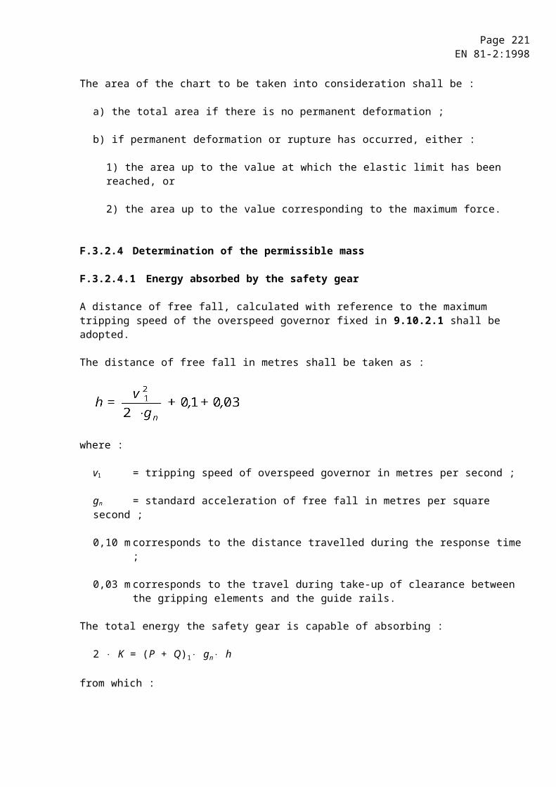
Page 221EN 81-2:1998
48) F5 = 1,4 gn [cm (P + Q) + 0,64 Pr + Pm + Prt]
48) Valid for rams extending in upward direction.

Page 222EN 81-2:1998
K.2.3 Telescopic jacks with external guidance
Figure K.7
For n ³ 100 : For n 100 :
49)
49) Valid for rams extending in upward direction.
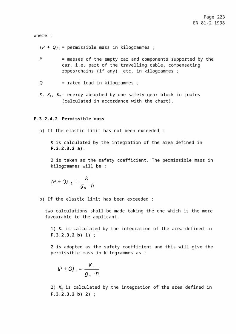
Page 223EN 81-2:1998
Symbols :
An = cross-sectional area of the material of the ram to be calculated in square millimetres (n =1,2,3) ;
cm = reeving ratio ;
dm = outside diameter of the biggest ram of a telescopic jack in millimetres ;
dmi = inner diameter of the biggest ram of a telescopic jack in millimetres ;
E = modulus of elasticity in newtons per square millimetre ;(for steel : E = 2,1 x 10⁵ N/mm2) ;
eo = additional wall thickness in millimetres ;
Fs = actual buckling force applied in newtons ;
gn = standard acceleration of free fall in metres per square second ;
ie = equivalent radius of gyration of a telescopic jack in millimetres ;
in = radius of gyration of the ram to be calculated in millimetres (n =1,2,3) ;
Jn = second moment of area of the ram to be calculated in fourth power millimetres(n = 1, 2, 3) ;
l = maximum length of rams subject to buckling in millimetres ;
p = full load pressure in megapascals ;
P = sum of the mass of the empty car and the mass of the portion of the travelling cables suspended from the car in kilogrammes ;
Pr = mass of the ram to be calculated in kilogrammes ;
Prh = mass of the ram head equipment, if any in kilogrammes ;
Prt = mass of the rams acting on the ram to be calculated (in the case of telescopic jacks) in kilogrammes
Q = rated load (mass) displayed in the car in kilogrammes ;
Rm = tensile strength of material in newtons per square millimetre ;
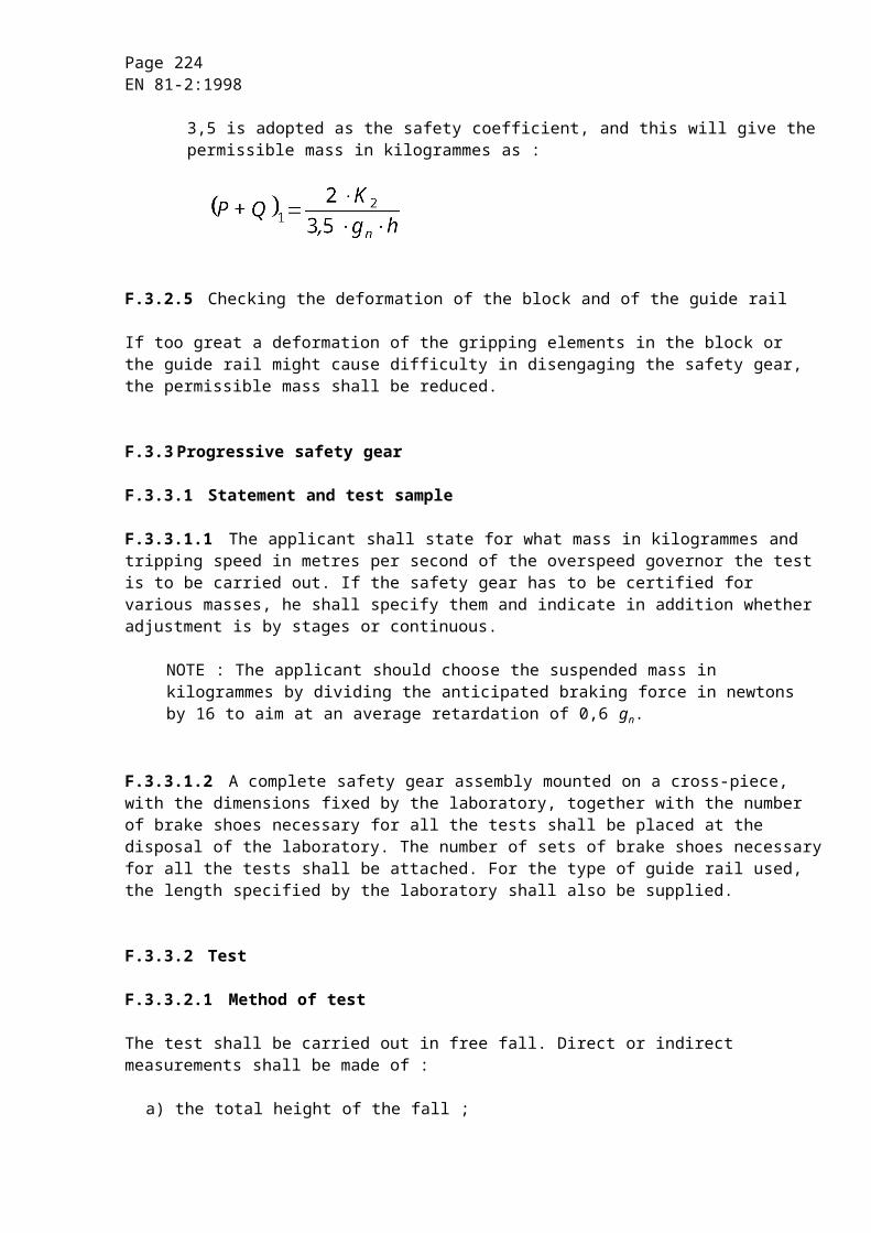
Page 224EN 81-2:1998
RP0,2 = proof stress (non-proportional elongation) in newtons per square millimetre ;
e = = equivalent coefficient of slenderness of a telescopic jack ;
n = = coefficient of slenderness of the ram to be calculated ;
, = factors used to represent approximate values given by experimentally determined diagrams ;
1,4 = over pressure factor ;
2 = safety factor against buckling.
Page 225EN 81-2:1998
Annex ZA (informative)
Clauses of this standard addressing essential requirements or other provisions of EU Directives
This Standard has been prepared under a Mandate given to CEN by the European Commission and the European Free Trade Association, and supports essential requirements of Directive relating to lift (95/16/EC).
Standards covering particular applications (e.g. accessibility for disabled, vandalism, intensive use) are under consideration.
WARNING : Other requirements and other EU Directive may be applicable to the product(s) falling within the scope of this standard.
The clauses of this standard are likely to support requirements of Directive relating to lift.
Compliance with the clauses of this standard provides one means of conforming with the specific essential requirements of the Directive concerned and associated EFTA regulations.
NOTE 1 : Regarding 6.2, 6.3 and 6.4 see clause 0.2.2 of this standard
NOTE 2 : Footnote of 5.2.1.2 implies that the installation of lifts with partially enclosed wells may be subject to the authorization of national authorities.