Reset-Free Polarization Tracker –PolaStay™
5
GP-DS-POS-002-23 9/27/13 General Photonics Corp. 5228 Edison Ave. Chino, CA 91710 Tel: 909.590.5473 Fax: 909.902.5536 Email: [email protected] Website: www.generalphotonics.com Reset-Free Polarization Tracker –PolaStay™ Operating Wavelength Range 1 1310 or 1550 ± 50 nm SOP recovery time < 3 ms (0.9 ms typical) SOP rotation tracking speed (reset free) 47π/s SOP accuracy 2 < 0.1 dB Repeatability 2 < 0.1 dB Insertion loss Internal feedback: 0.8 dB typical, 1.2 dB max. External feedback: <0.1 dB Return loss > 50 dB Isolation in orthogonal polarization 20 dB Optical input power −20 dBm to 20 dBm standard for internal feedback version (low power option available) External feedback voltage 0 to 4.6 volts for external feedback version Optical Power Handling 20 dBm max., higher possible Optical Power Damage Threshold 300 mW Operating Temperature 0 to 70°C Storage Temperature −20 ~ 70 °C Power Supply +12 VDC / 0.5A −12VDC / 0.15A Applications: PMD compensation Polarization demultiplexing Elimination of polarization fading Coherent detection Ordering Information: POS – 002 – X – XX – XX – XXX Unique Features: Preliminary Specifications The PolaStay™ polarization tracker automatically adjusts the state of polarization (SOP) towards a reference SOP, counteracting continuous input SOP variations as fast as 0.9 ms with no resets. The reference SOP is determined by a feedback signal which can be provided either internally or externally. The internal feedback version (POS-002-I) consists of a fiber squeezer polarization controller, in-line polarization monitor, digital and analog circuits, and proprietary algorithm. The error signal from the polarization monitor is fed back to the polarization controller to maintain a linear SOP at the output. The external feedback version (POS-002-E) replaces the internal polarization monitor with an external analog electrical feedback signal of the user’s choice, such as a voltage proportional to the degree of polarization (DOP) measured by a polarimeter, the bit-error rate (BER) from a BER chip, the RF spectrum of a detected signal, or the optical power after a polarizer. The output fiber can be either single mode fiber or PM fiber with the SOP aligned to its slow axis. This module can be used for PMD compensation, polarization division demultiplexing, elimination of polarization fading in coherent detection and fiber sensor systems, suppression of noise figure in optical amplifiers, and reduction of PDL effects. Plug and play 47π/s tracking speed 0.9 ms recovery time Reset free operation Communications Interface 3 RS-232 Dimensions 0.75”(H) x 3.8” (W) x 7.25” (L) Notes: Unless otherwise noted, specifications listed above are for the standard configuration with internal feedback option, without connectors; specs may be different for instruments with different wavelength or input power ranges. 1. Other wavelength ranges and control algorithms may be available upon request. 2. The output power fluctuation caused by SOP fluctuation after passing through a polarizer. 3. Requires a special cable (included). POS-002 Output fiber type: Wavelength: 13 = 1310nm 15 = 1550nm Feedback I: Internal E: External SM PM Connector Type: FC/PC, FC/APC, SC/PC, SC/APC Others specify
Transcript of Reset-Free Polarization Tracker –PolaStay™
GP-DS-POS-002-23 9/27/13
General Photonics Corp. 5228 Edison Ave. Chino, CA 91710
Tel: 909.590.5473 Fax: 909.902.5536
Email:
Website:
www.generalphotonics.com
Reset-Free Polarization Tracker –PolaStay™
Operating Wavelength Range1 1310 or 1550 ± 50 nm
SOP recovery time < 3 ms (0.9 ms typical) SOP rotation tracking speed (reset free) 47π/s
SOP accuracy2 < 0.1 dB
Repeatability2 < 0.1 dB
Insertion loss Internal feedback: 0.8 dB typical, 1.2 dB max. External feedback: <0.1 dB
Return loss > 50 dB Isolation in orthogonal polarization 20 dB
Optical input power −20 dBm to 20 dBm standard for internal feedback version (low power option available)
External feedback voltage 0 to 4.6 volts for external feedback version
Optical Power Handling 20 dBm max., higher possible Optical Power Damage Threshold 300 mW
Operating Temperature 0 to 70°C
Storage Temperature −20 ~ 70 °C
Power Supply +12 VDC / 0.5A −12VDC / 0.15A
Applications:
PMD compensation Polarization demultiplexing Elimination of polarization fading Coherent detection
Ordering Information:
POS – 002 – X – XX– XX– XXX
Unique Features:
Preliminary Specifications
The PolaStay™ polarization tracker automatically adjusts the state of polarization (SOP) towards a reference SOP, counteracting continuous input SOP variations as fast as 0.9 ms with no resets. The reference SOP is determined by a feedback signal which can be provided either internally or externally. The internal feedback version (POS-002-I) consists of a fiber squeezer polarization controller, in-line polarization monitor, digital and analog circuits, and proprietary algorithm. The error signal from the polarization monitor is fed back to the polarization controller to maintain a linear SOP at the output. The external feedback version (POS-002-E) replaces the internal polarization monitor with an external analog electrical feedback signal of the user’s choice, such as a voltage proportional to the degree of polarization (DOP) measured by a polarimeter, the bit-error rate (BER) from a BER chip, the RF spectrum of a detected signal, or the optical power after a polarizer. The output fiber can be either single mode fiber or PM fiber with the SOP aligned to its slow axis. This module can be used for PMD compensation, polarization division demultiplexing, elimination of polarization fading in coherent detection and fiber sensor systems, suppression of noise figure in optical amplifiers, and reduction of PDL effects.
Plug and play 47π/s tracking speed 0.9 ms recovery time Reset free operation
Communications Interface3 RS-232
Dimensions 0.75”(H) x 3.8” (W) x 7.25” (L) Notes: Unless otherwise noted, specifications listed above are for the standard configuration with internal feedback option, without connectors; specs may be different for instruments with different wavelength or input power ranges. 1. Other wavelength ranges and control algorithms may be available upon request. 2. The output power fluctuation caused by SOP fluctuation after passing through a polarizer. 3. Requires a special cable (included).
POS-002
Output fiber type: Wavelength: 13 = 1310nm 15 = 1550nm
Feedback I: Internal E: External
SM PM
Connector Type: FC/PC, FC/APC, SC/PC, SC/APC Others specify
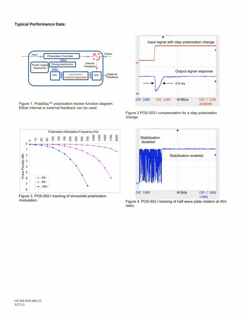
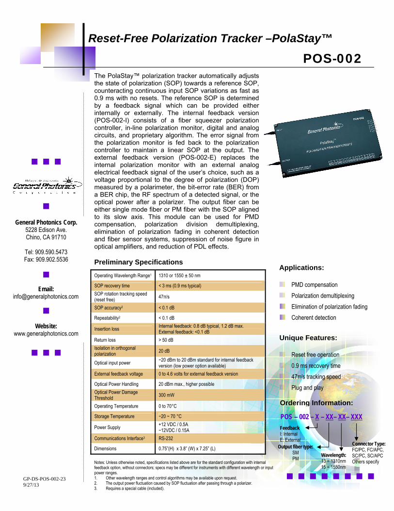
Typical Performance Data:
Figure 1. PolaStay™ polarization tracker function diagram. Either internal or external feedback can be used.
Figure 2 POS-002-I compensation for a step polarization change.
0
1
2
3
4
5
6
7
8
0 10 25 50 100
125
150
200
250
500
750
1000
1250
1500
1750
2000
Polarization Modulation Frequency (Hz)
Pow
er P
enal
ty (d
B)
40◦90◦180◦
Figure 3. POS-002-I tracking of sinusoidal polarization modulation.
Figure 4. POS-002-I tracking of half-wave plate rotation at 45π rad/s.
Input signal with step polarization change
Driving electronics
A/D
Electronics Power supply
D/A µ-processor Control Algorithm
Polarization Controller
Internal Feedback
External Feedback
Input Output
Output signal response
0.5 ms
Stabilization disabled
Stabilization enabled
GP-DS-POS-002-23 9/27/13
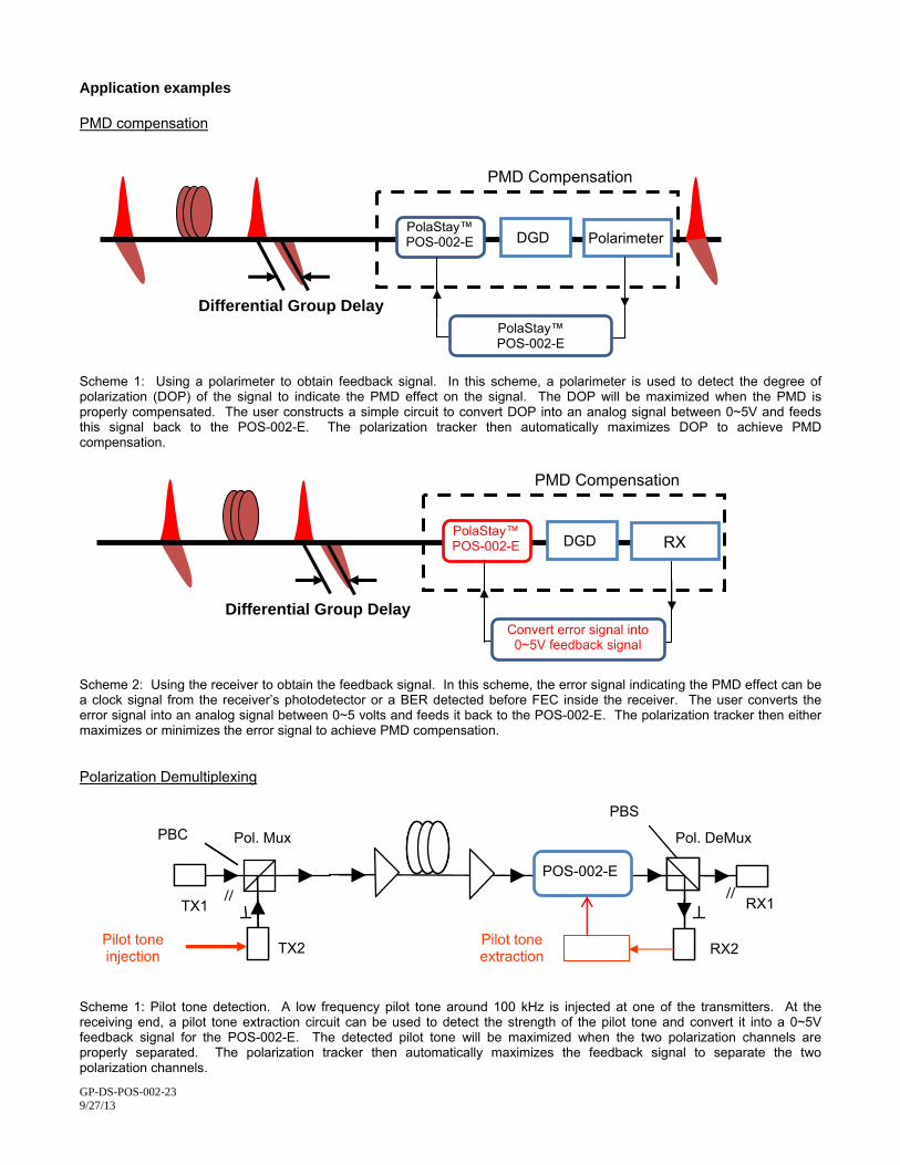
Application examples PMD compensation
GP-DS-POS-002-23 9/27/13
Scheme 1: Using a polarimeter to obtain feedback signal. In this scheme, a polarimeter is used to detect the degree of polarization (DOP) of the signal to indicate the PMD effect on the signal. The DOP will be maximized when the PMD is properly compensated. The user constructs a simple circuit to convert DOP into an analog signal between 0~5V and feeds this signal back to the POS-002-E. The polarization tracker then automatically maximizes DOP to achieve PMD compensation.
Scheme 2: Using the receiver to obtain the feedback signal. In this scheme, the error signal indicating the PMD effect can be a clock signal from the receiver’s photodetector or a BER detected before FEC inside the receiver. The user converts the error signal into an analog signal between 0~5 volts and feeds it back to the POS-002-E. The polarization tracker then either maximizes or minimizes the error signal to achieve PMD compensation. Polarization Demultiplexing
Scheme 1: Pilot tone detection. A low frequency pilot tone around 100 kHz is injected at one of the transmitters. At the receiving end, a pilot tone extraction circuit can be used to detect the strength of the pilot tone and convert it into a 0~5V feedback signal for the POS-002-E. The detected pilot tone will be maximized when the two polarization channels are properly separated. The polarization tracker then automatically maximizes the feedback signal to separate the two polarization channels.
Differential Group Delay
PMD Compensation
PolaStay™ POS-002-E DGD RX
Convert error signal into 0~5V feedback signal
Differential Group Delay
PMD Compensation
POS-002-E PolaStay™ Polarimeter DGD
PolaStay™ POS-002-E
PBS
TX1
TX2
RX1
RX2
PBC
// //
Pol. Mux
Pol. DeMux
Pilot tone injection
Pilot tone extraction
POS-002-E
PBS
GP-DS-POS-002-23 9/27/13
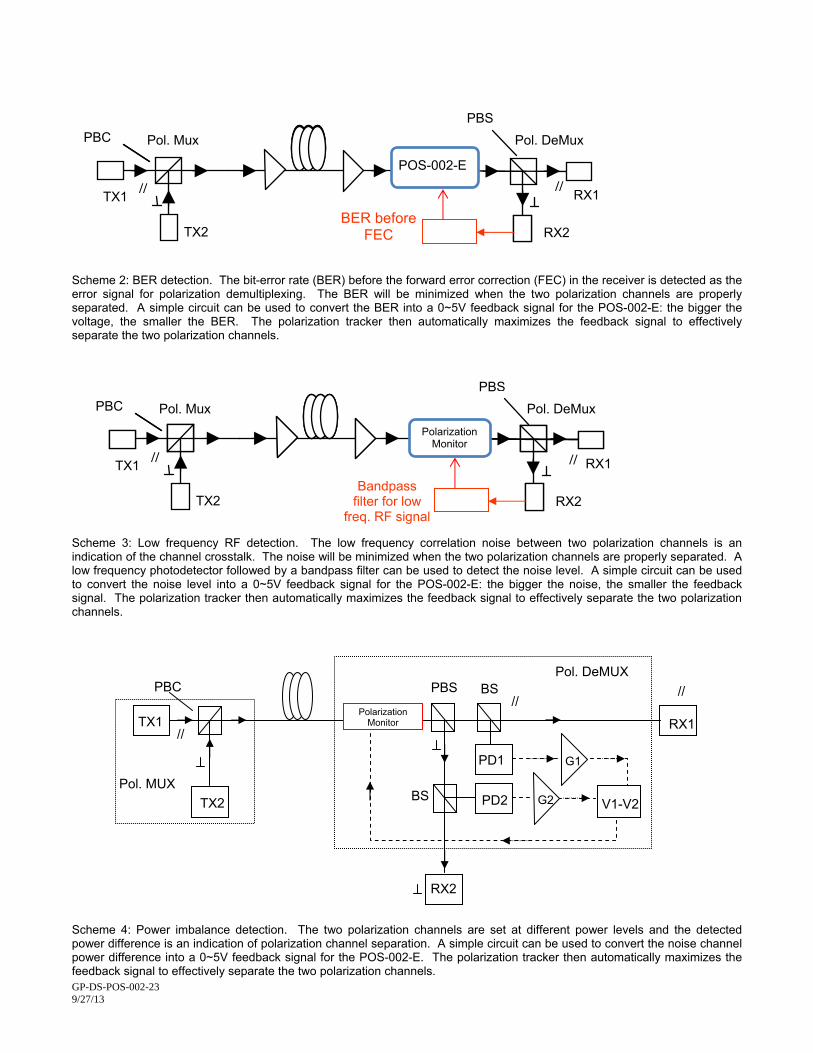
feedback signal to effectively separate the two polarization channels.
Scheme 2: BER detection. The bit-error rate (BER) before the forward error correction (FEC) in the receiver is detected as the error signal for polarization demultiplexing. The BER will be minimized when the two polarization channels are properly separated. A simple circuit can be used to convert the BER into a 0~5V feedback signal for the POS-002-E: the bigger the voltage, the smaller the BER. The polarization tracker then automatically maximizes the feedback signal to effectively separate the two polarization channels.
Scheme 3: Low frequency RF detection. The low frequency correlation noise between two polarization channels is an indication of the channel crosstalk. The noise will be minimized when the two polarization channels are properly separated. A low frequency photodetector followed by a bandpass filter can be used to detect the noise level. A simple circuit can be used to convert the noise level into a 0~5V feedback signal for the POS-002-E: the bigger the noise, the smaller the feedback signal. The polarization tracker then automatically maximizes the feedback signal to effectively separate the two polarization channels.
Scheme 4: Power imbalance detection. The two polarization channels are set at different power levels and the detected power difference is an indication of polarization channel separation. A simple circuit can be used to convert the noise channel power difference into a 0~5V feedback signal for the POS-002-E. The polarization tracker then automatically maximizes the
TX1
TX2
RX1
RX2
PBC
// //
Pol. Mux
Pol. DeMux
BER before
FEC
POS-002-E
PBS
TX1
TX2
RX1
RX2
PBC
// //
Pol. Mux
Pol. DeMux Polarization
Monitor
Bandpass filter for low
freq. RF signal
Pol. DeMUX
PBC PBS BS
//
//
TX2
RX1
RX2
TX1 Polarization
Monitor
PD2
PD1
V1-V2
//
BS Pol. MUX
G1
G2
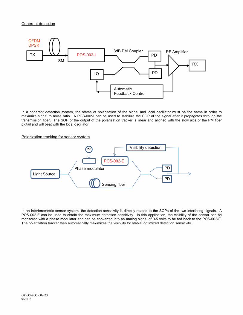
Coherent detection
GP-DS-POS-002-23 9/27/13
In a coherent detection system, the states of polarization of the signal and local oscillator must be the same in order to
aximize signal to noise ratio. A POS-002-I can be used to stabilize the SOP of the signal after it propagates through the
olarization tracking for sensor system
mtransmission fiber. The SOP of the output of the polarization tracker is linear and aligned with the slow axis of the PM fiber pigtail and will beat with the local oscillator. P
gnals. A OS-002-E can be used to obtain the maximum detection sensitivity. In this application, the visibility of the sensor can be
In an interferometric sensor system, the detection sensitivity is directly related to the SOPs of the two interfering siPmonitored with a phase modulator and can be converted into an analog signal of 0-5 volts to be fed back to the POS-002-E. The polarization tracker then automatically maximizes the visibility for stable, optimized detection sensitivity.
SM
TX POS-002-I PD
PD
3dB PM Coupler RF Amplifier
OFDM DPSK
RX
LO
Automatic Feedback Control
POS-002-E
Sensing fiber
Phase modulator
~
PD
PD
Visibility detection
Light Source