Recovery of overnitrided steel Paper - gianottielio.it · It is well known as in nitriding process...
11
1 di 11 RECOVERY OF OVERNITRIDED STEEL SURFACE WITH EPSILON (ε) LAYER PHASE DEPTH RESTORATION. Elio Gianotti. Heat Treatment Ferioli e Gianotti S.p.A. Torino Italy. INTRODUCTION It is well known as in nitriding process the ammonia dissociation equilibrium is easy to reach and its rate is industrially acceptable. So that, the nitrogen diffusion rate in the α iron lattice and the γ-ε nitride formation are. While the solid compound formation like γ and ε nitride and the nitrogen solid solution move the ammonia equilibrium toward the dissociation, the same not allow practically to the equilibrium go back also in the case, purely theoretical, that the thermodynamics equilibrium may allow it, because the solid compound decrease to zero the reaction rate in the opposite direction. So really the nitriding process is, in practice, not reversible and the “de-nitriding” impossible. When the nitriding process is carried out with too high nitrogen potential, the surface of heat treated pieces have a white layer too depth and under this some intergranular thin layer of ε phase, called “angel’s hairs” by the French. This microstructure is extremely brittle and normally the pieces are rejected as scraps (see fig.1). Fig.1 Microstructure × 1000. 40NiCrMo4 overnitrided steel. ε intercristalline phase under the white layer. In this case, however, also if it’s impossible to destroy the white layer, we can mitigate the over nitriding effect by long soaking time in a neutral atmosphere, in the same furnace and the same temperature of the overnitriding process.
Transcript of Recovery of overnitrided steel Paper - gianottielio.it · It is well known as in nitriding process...
1 di 11
RECOVERY OF OVERNITRIDED STEEL SURFACE WITH EPSILON (ε) LAYER PHASE DEPTH RESTORATION.
Elio Gianotti. Heat Treatment Ferioli e Gianotti S.p.A. Torino Italy.
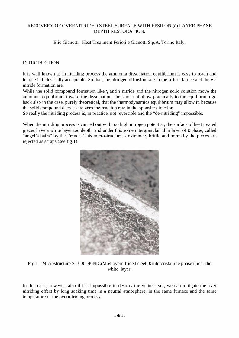
INTRODUCTION It is well known as in nitriding process the ammonia dissociation equilibrium is easy to reach and its rate is industrially acceptable. So that, the nitrogen diffusion rate in the α iron lattice and the γ-ε nitride formation are. While the solid compound formation like γ and ε nitride and the nitrogen solid solution move the ammonia equilibrium toward the dissociation, the same not allow practically to the equilibrium go back also in the case, purely theoretical, that the thermodynamics equilibrium may allow it, because the solid compound decrease to zero the reaction rate in the opposite direction. So really the nitriding process is, in practice, not reversible and the “de-nitriding” impossible. When the nitriding process is carried out with too high nitrogen potential, the surface of heat treated pieces have a white layer too depth and under this some intergranular thin layer of ε phase, called “angel’s hairs” by the French. This microstructure is extremely brittle and normally the pieces are rejected as scraps (see fig.1).
Fig.1 Microstructure × 1000. 40NiCrMo4 overnitrided steel. εεεε intercristalline phase under the white layer.
In this case, however, also if it’s impossible to destroy the white layer, we can mitigate the over nitriding effect by long soaking time in a neutral atmosphere, in the same furnace and the same temperature of the overnitriding process.
2 di 11
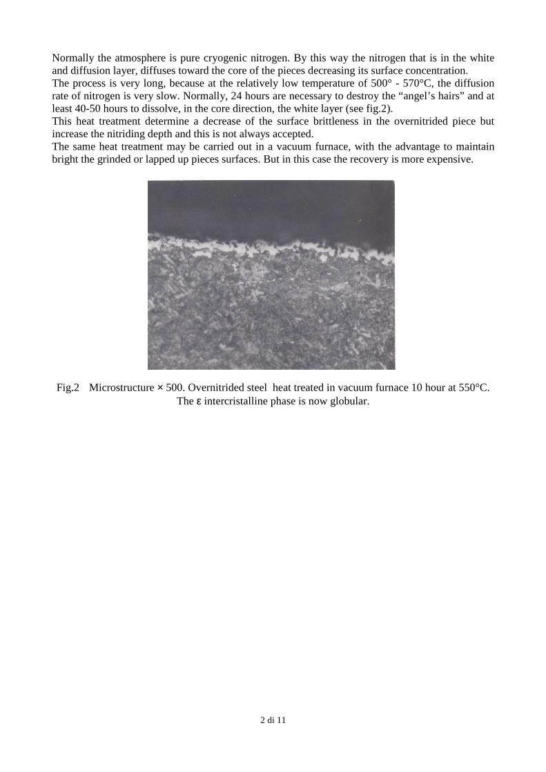
Normally the atmosphere is pure cryogenic nitrogen. By this way the nitrogen that is in the white and diffusion layer, diffuses toward the core of the pieces decreasing its surface concentration. The process is very long, because at the relatively low temperature of 500° - 570°C, the diffusion rate of nitrogen is very slow. Normally, 24 hours are necessary to destroy the “angel’s hairs” and at least 40-50 hours to dissolve, in the core direction, the white layer (see fig.2). This heat treatment determine a decrease of the surface brittleness in the overnitrided piece but increase the nitriding depth and this is not always accepted. The same heat treatment may be carried out in a vacuum furnace, with the advantage to maintain bright the grinded or lapped up pieces surfaces. But in this case the recovery is more expensive.
Fig.2 Microstructure × 500. Overnitrided steel heat treated in vacuum furnace 10 hour at 550°C. The ε intercristalline phase is now globular.
3 di 11
IONIC DISCHARGE INFLUENCE ON THE NITRIDING RATE I have early told that the nitriding reaction process is irreversible, whether because the thermodynamic equililibrium of the NH3 dissociation has a negative ∆G (molar free enthalpy), or for the formation of solid phase like the nitride. Different are the workings conditions and the chemicals-physic states of the superficial layer in the case of plasma nitriding. When this heat treatment is goings on, because the ionic discharge, a series of interaction, listed in table 1, come out.
Process Mechanisms / species involved
Activation De-absorption of impurity Increase in number of defect ( dislocation density ) Localised temperature increase
Implantation Ions : N+
Sputtering Fe, FeN, FeNxHy
Absorption Ions : N+, N2
+, NHx+
Neutral particle N, N2 , FeNxHy
Tab.1 List of phenomena’s generated by ionic discharge on the first 10 µm depth surface.
This process induces the formation of nitrogen ion-molecule particles between the pieces surface and the plasma. An amount of nitrogen will be absorbed by the pieces and will produces a compound and a diffusion layer. At the same time a sputtering process realizes by ionic and neutral particles on the pieces surface that are at the cathodic zone. By this way Fe, C, N, O atoms and Fe Nx etc. compounds come out from the pieces surfaces and go in the plasma around those; or fall again at the pieces surfaces. The solid compound, ε and γ nitride, formed by the nitriding reaction are then in equilibrium with the relative gaseous-phase, that is forming by sputtering, near the pieces surface and can actively enter in the reaction equilibrium. The reaction is now no more irreversible. We have, at this point, to verify the equilibrium of a nitrided surface with a pure hydrogen transformed in plasma by the ionic discharge. The nitrided surface is formed by ε and γ nitride, but also C like Fe3 C is present originally in the steel. So we can have beside the “de-nitriding” process also a decarburising effect that is dangerous for the steel. SURFACE CARBON EQUILIBRIUM TO AVOID DECARBURISING It’s well known that hydrogen can react with the carbon of the steel to form hydrocarbons. The synthesis reaction is industrially used in the magnetic thin sheet steel annealing at temperature up 900°C, because in this case there’s a necessity to decrease the carbon content the most possible. We need to check the thermodynamic equilibrium of the synthesis reaction, to verify if it’s possible also at nitriding temperature of 550°C, that’s 823 K. 1) 1/2Fe3 C + H2 ↔ 1/2CH4 + 3/2Fe ∆G = -5798 cal a 823 K
4 di 11
The free enthalpy ensues negative, so the equilibrium at 550°C go from left to right. Naturally the negative free enthalpy tell us that’s possible the reaction, but don’t give its rate value; so that this parameter will be later examined. The reaction equilibrium constant Kp value will be obtained by utilizing the thermodynamic equations: 5798 LgeKp = ----------------------- = 1.54 ; K = e1.54 = 4.66 at 823 K 1.987 · 823 · lge10 So we can write the reaction equilibrium constant at 823 K that’s p(CH4)
1\2 Kp = -------------- = 4.66 p(H2) In the vacuum furnace, with ionic discharge, the work pressure may be about 2-3 mbar – So we have to seek the partial pressure of CH4 and H2 that corresponds with ∆G (free enthalpy) equal to 0 because, in these condition, we can avoid decarburising process. If we consider the pressure of the ionic discharge at about 2.5 mbar we can write: p(CH4) + p(H2) = 2.5 · 10-3 p(CH4)
1/2
------------- = 4.66 p(H2) The system solution will be: p(CH4) = 1.2 · 10-4 mbar and p(H2) = 2.38 · 10-3 mbar This means that the CH4
in the vacuum atmosphere may be about 5% of the hydrogen–methane mixture. NITRIDING EQUILIBRIUM If we consider the nitrogen solid solution in the α iron lattice we can use the dissociation equilibrium of NH3 2NH3 ↔ N2 + 3H2 Otherwise, if we have to react the nitrogen compound like Fe2N (ε phase) and Fe4N (γ phase) in the white layer of the nitrided steel surface, we have to consider the following equilibrium at about 550°C 2) 2/3Fe2N + H2 → 4/3Fe + 2/3NH3 ∆G = +648 cal at 823K The free enthalpy variation is positive, so the equilibrium go from the right to left. In fact the nitriding process is realizing because of this equilibrium. The equilibrium constant Kp is
5 di 11
-648 p(NH3)2/3
lgeK = --------------------- = -0.17 by this we obtain: Kp = e–0.17 = 0.84 = -------------- 1.987 · 823·lge10 p(H2) Now we have to consider that to avoid decarburising in the vacuum furnace the hydrogen partial pressure, before calculated, must be about 2.38·10-3 bar. If we put this value in the above reaction equilibrium we will obtain that the ammonia partial pressure will be equal to 1·10-4 bar. This value is very little but is not zero. If we repeat the calculation with the γ phase equilibrium, we’ll obtain that ammonia partial pressure, versus hydrogen 2.38·10-3 bar partial pressure, is 6·10-5 bar. We can consequently to assert that, if the rate of the reaction equilibrium is speedy enough, for every 1000 ml of hydrogen that enter in the vacuum furnace, about 42 to 25 ml of ammonia are eliminated by the vacuum pump. EXPERIMENTAL PART If the ionic process is carried out by hydrogen flow is valid the equilibrium of the reaction 2). In this case the hydrogen flow remove continuously the plasma atmosphere around the nitrided pieces. So the forming ammonia is continuously eliminated through the vacuum pump and allows to other nitrided compound to enter in the equilibrium of the renewed gaseous atmosphere, until to arrive at the total nitrides elimination from the surface. For to avoid the C loss of the steel, a methane flow will be added at hydrogen, in such a quantity, to settle the reaction equilibrium. The de-nitriding test has been carried out in a industrial furnace with heater and insulation made in graphite. The partial pressure in the vacuum furnace is maintained varying the rotary pump speed. By this way it’s possible to change the gas flow proportionally to surface dimension of the pieces to be recovered, without to influence the pressure parameter. The ionic discharge intensity and the partial pressure parameter are the same of the nitriding process. The temperature may be the same of the nitriding or higher but in any case doesn’t have to exceed the tempering value utilized in the previous quenching and tempering heat treatment of the steel. The nitrided pieces utilized for the de-nitriding process, had been submitted to salt bath nitriding for four hour to 570°C. The nitrided layer data were the below: Surface hardness: HV0.5 = 690 ; HV1 = 600 White layer depth: 8-9 µm Diffusion layer: about 0.3 mm Intergranular ε phase (Angel’s hairs): just under the white layer Effective case depth (core hardness + 100 HV1): 0.21 mm
C 0.40 % Mn 0.83 % Si 0.36 % Cu 0.17 % Cr 1.1 % Ni 0.14 % Mo 0.20 %
Tab.2 Chemical composition of nitrided pieces
6 di 11
The pieces nitrided as above, have been undergone to the recovery heat treatment in the described facilities for a 15 hours lasting plasma discharge and at 550°C temperature. The H2 and CH4 flow composition have been 95% and 5% respectively, with an atmosphere change of about 5000 ml/1. When the process was accomplished the pieces were cooled by cryogenic nitrogen. The following are the obtained data: - Surface hardness HV0.5 = 610; HV1 = 530 - White layer no more continuous but like isle of about 2-3 µm diameter
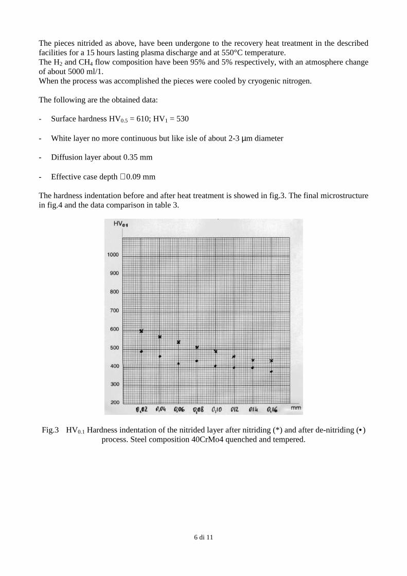
- Diffusion layer about 0.35 mm - Effective case depth ∼ 0.09 mm The hardness indentation before and after heat treatment is showed in fig.3. The final microstructure in fig.4 and the data comparison in table 3.
Fig.3 HV0.1 Hardness indentation of the nitrided layer after nitriding (*) and after de-nitriding (•) process. Steel composition 40CrMo4 quenched and tempered.
7 di 11
DATA
NITRIDED DE-NITRIDED
Surface hardness HV1
HV0.5 White layer µm Diffusion depth mm Effective case depth ( core hardness + 100 HV1 )
600 690
8-9
0.3
0.21
530 610
2-3
0.35
0.09
Tab.3 Data comparison before and after de-nitriding
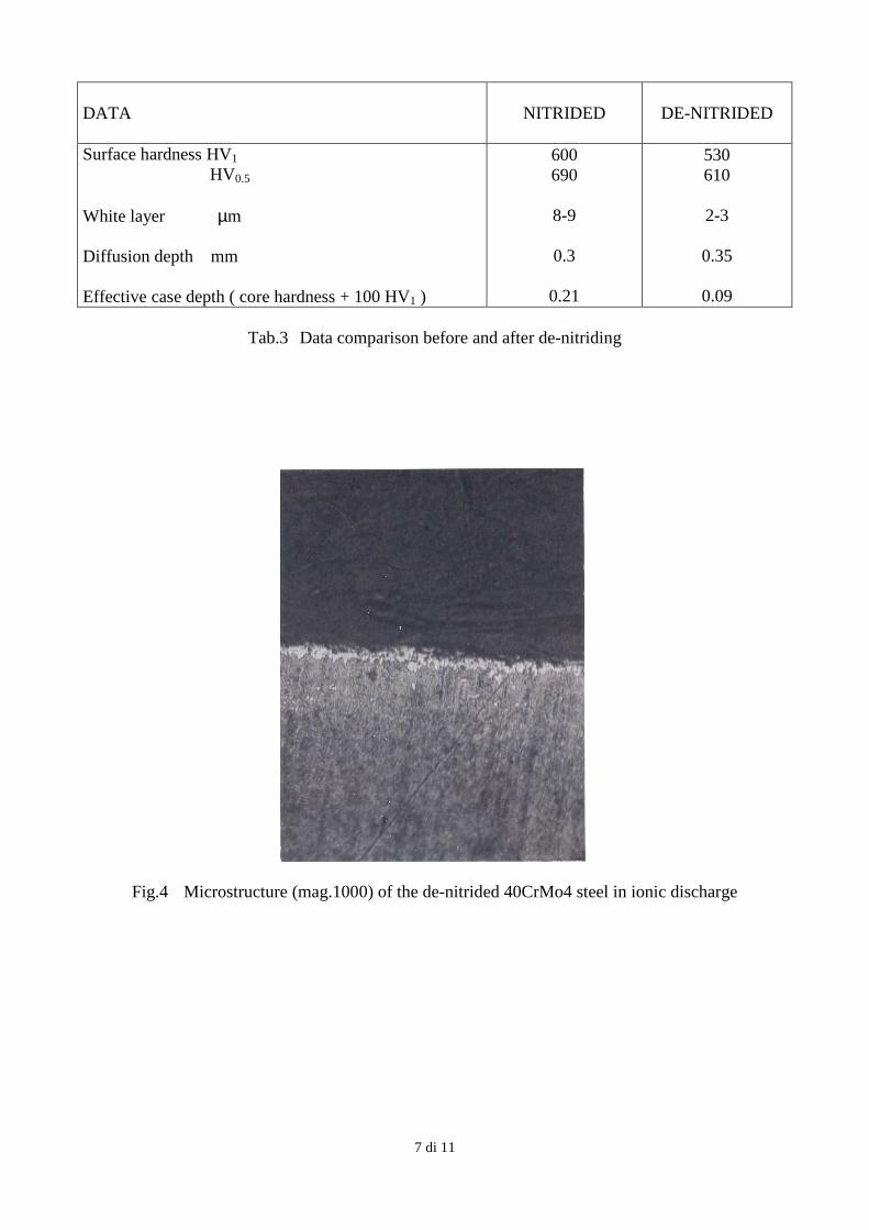
Fig.4 Microstructure (mag.1000) of the de-nitrided 40CrMo4 steel in ionic discharge
8 di 11
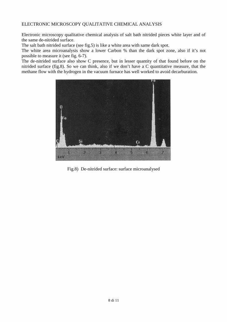
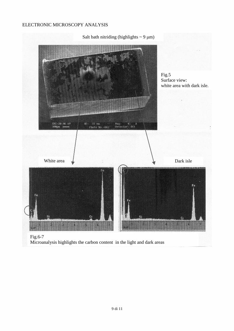
ELECTRONIC MICROSCOPY QUALITATIVE CHEMICAL ANALYSIS Electronic microscopy qualitative chemical analysis of salt bath nitrided pieces white layer and of the same de-nitrided surface. The salt bath nitrided surface (see fig.5) is like a white area with same dark spot. The white area microanalysis show a lower Carbon % than the dark spot zone, also if it’s not possible to measure it (see fig. 6-7). The de-nitrided surface also show C presence, but in lesser quantity of that found before on the nitrided surface (fig.8). So we can think, also if we don’t have a C quantitative measure, that the methane flow with the hydrogen in the vacuum furnace has well worked to avoid decarburation.
Fig.8) De-nitrided surface: surface microanalysed
9 di 11
ELECTRONIC MICROSCOPY ANALYSIS
Fig.5 Surface view: white area with dark isle.
White area Dark isle
Fig.6-7 Microanalysis highlights the carbon content in the light and dark areas
Salt bath nitriding (highlights ~ 9 µm)
10 di 11
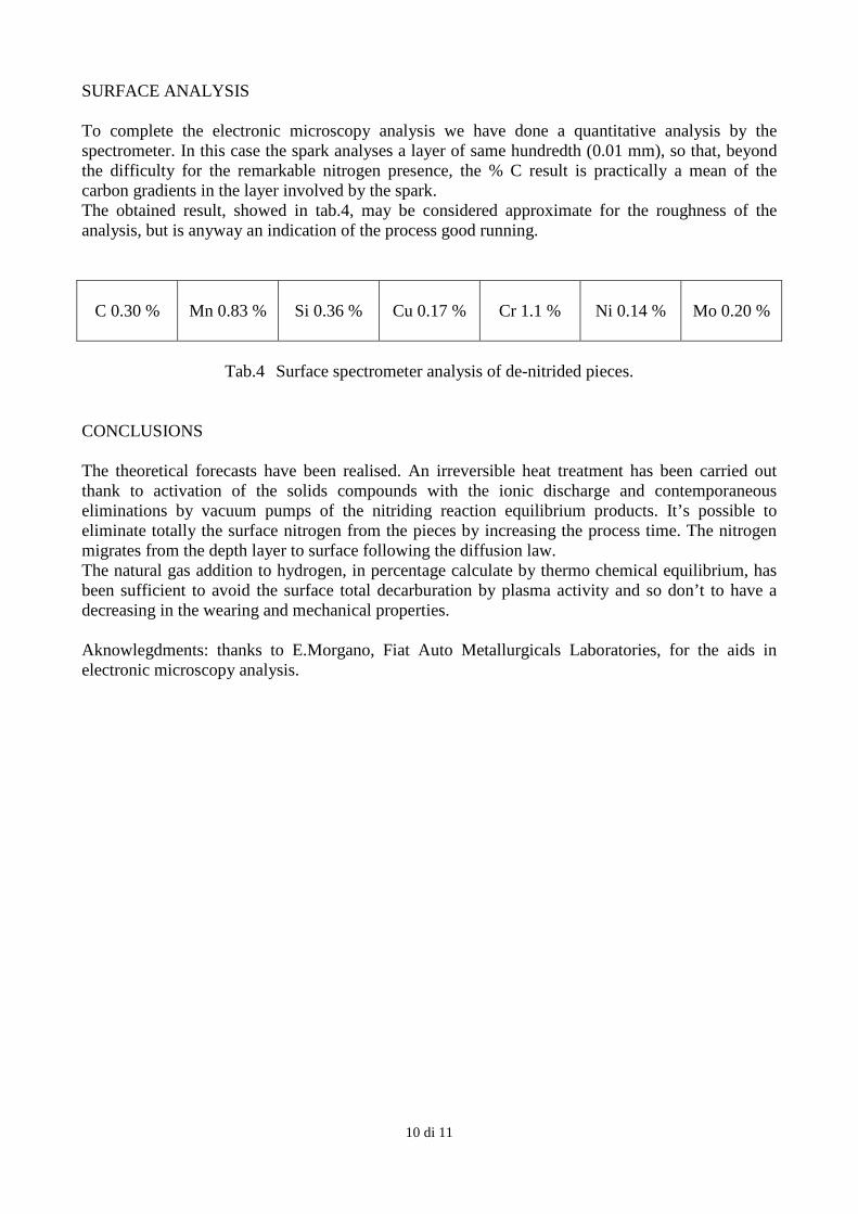
SURFACE ANALYSIS To complete the electronic microscopy analysis we have done a quantitative analysis by the spectrometer. In this case the spark analyses a layer of same hundredth (0.01 mm), so that, beyond the difficulty for the remarkable nitrogen presence, the % C result is practically a mean of the carbon gradients in the layer involved by the spark. The obtained result, showed in tab.4, may be considered approximate for the roughness of the analysis, but is anyway an indication of the process good running.
C 0.30 %
Mn 0.83 % Si 0.36 % Cu 0.17 % Cr 1.1 % Ni 0.14 % Mo 0.20 %
Tab.4 Surface spectrometer analysis of de-nitrided pieces.
CONCLUSIONS The theoretical forecasts have been realised. An irreversible heat treatment has been carried out thank to activation of the solids compounds with the ionic discharge and contemporaneous eliminations by vacuum pumps of the nitriding reaction equilibrium products. It’s possible to eliminate totally the surface nitrogen from the pieces by increasing the process time. The nitrogen migrates from the depth layer to surface following the diffusion law. The natural gas addition to hydrogen, in percentage calculate by thermo chemical equilibrium, has been sufficient to avoid the surface total decarburation by plasma activity and so don’t to have a decreasing in the wearing and mechanical properties. Aknowlegdments: thanks to E.Morgano, Fiat Auto Metallurgicals Laboratories, for the aids in electronic microscopy analysis.
11 di 11
ABSTRACT It is well known as in nitriding process the ammonia dissociation equilibrium is easy to reach and its rate is industrially acceptable. So that , the nitrogen diffusion rate in the α iron lattice and the γ- ε nitride formation are. While the solid compound formation like γ and ε nitride and the nitrogen solid solution move the ammonia equilibrium toward the dissociation, the same not allow practically to the equilibrium go back also in the case, purely theoretical, that the thermodynamics equilibrium may allow it, because the solid compound decrease to zero the reaction rate in the opposite direction. So really the nitriding process is, in practice, not reversible and the “denitriding” impossible. When the nitriding process is carried out with too high nitrogen potential, the surface of heat treated pieces have a white layer too depth and under this some intergranular thin layer of ε phase, called “angel’s hairs” by the French. This microstructure is extremely brittle and normally the pieces are rejected as scraps. In this work we describe the use of a plasma nitriding furnace for the recovery of the over nitrided pieces. This process utilize hydrogen and some amount of hydrocarbon to create the plasma discharge. A sputtering process, due to the ion and fast neutral bombardment occurs at the cathode surface. Atoms like Fe, C, N, O, and compounds like oxides, FeN etc. are removed from surface and enter in the plasma atmosphere. In this way the solid compound like the nitride can enter in the equilibrium of the ammonia dissociation and may be eliminated through the vacuum pump. The amount of CH4 flow, to avoid decarburation during the process, will be calculated by thermodynamic data.
![Caractérisation et Dissociation du Complexe … · calcul des niveaux d'énergie du C60 par la méthode de Hückelii,iii. 3 Figure 1 : le fullerène[60] ... Le C60 est constitué](https://static.fdocument.org/doc/165x107/5b9cdae209d3f2f94c8d53c6/caracterisation-et-dissociation-du-complexe-calcul-des-niveaux-denergie-du.jpg)


![Synthesis of nano [alpha]-alumina powders using ... · PDF fileand ammonia solution) and α-alumina seeding on the transformation temperature ... transformation process to α phase](https://static.fdocument.org/doc/165x107/5ab848dd7f8b9ac10d8cd0da/synthesis-of-nano-alpha-alumina-powders-using-ammonia-solution-and-alumina.jpg)