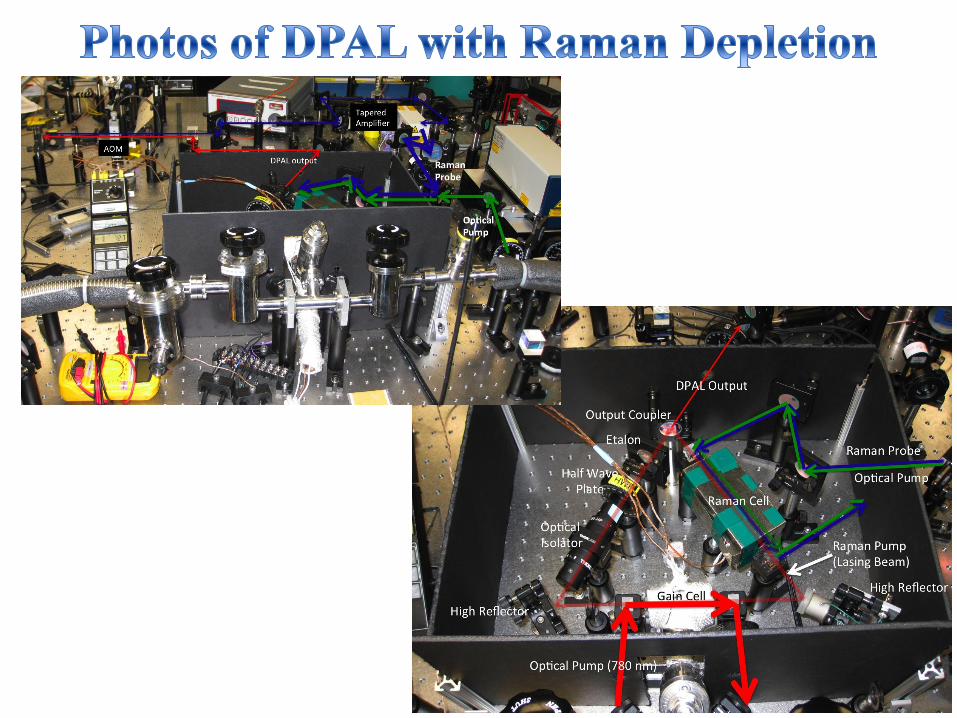
Raman Gain/Depletion Experiment
6
• At thermal equilibrium, F=2 and F=3 states are equally populated (k B T>>ΔE at room temp) • Optical pump effectively moves ground-state population from F=3 to F=2 • Raman Pump sees depletion, Raman Probe sees gain • Pump and Probe must be detuned because absorption is too high on resonance • Rb 85 vapor cell is magnetically shielded using μ-metal box • Raman Probe is downshifted from Raman Pump by 3.034 GHz (ground state hyperfine splitting in Rb 85 ) via double-pass AOM setup • Raman Pump and Probe are orthogonally polarized and copropagate through vapor – photodetectors monitor gain/depletion of these beams • Optical pump propagates slightly off- axis but still with good spatial overlap
Transcript of Raman Gain/Depletion Experiment
• At thermal equilibrium, F=2 and F=3 states are
equally populated (kBT>>ΔE at room temp)
• Optical pump effectively moves ground-state
population from F=3 to F=2
• Raman Pump sees depletion, Raman Probe sees gain
• Pump and Probe must be detuned because absorption
is too high on resonance
• Rb85 vapor cell is magnetically
shielded using μ-metal box
• Raman Probe is downshifted from
Raman Pump by 3.034 GHz (ground
state hyperfine splitting in Rb85) via
double-pass AOM setup
• Raman Pump and Probe are
orthogonally polarized and
copropagate through vapor –
photodetectors monitor
gain/depletion of these beams
• Optical pump propagates slightly off-
axis but still with good spatial
overlap
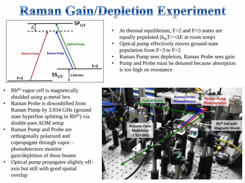
• AOM frequency scan centered around 3.034 GHz
• Saw up to 20% depletion of Raman pump
• FWHM ≈1 MHz for both Raman depletion dip and Raman gain peak
• Will need to use stronger Raman probe in order to more significantly deplete a more powerful Raman pump – AOM alone cannot do this
Raman Pump Depletion
Raman Probe Gain
1
2
than one. Hence, the resonant frequency shift with respect to the length variation decreases compared to the shift in an empty
cavity. For anomalous dispersion (ng<1), the frequency shift is
amplified to be equal to 1/ng times the amount of the shift in the empty
cavity.
In order to determine the actual value of R for an active cavity, we
need first to establish the explicit
dependence of on the lasing
frequency, . To this end, we first
solve Eq. (3.b) in steady state ( )
so that for . Since
is a function of E and , the
solution to the equation yields the
saturated electric field E in steady
state inside the laser cavity as a
function of the lasing frequency .
Let us consider the case in which
the cavity contains a medium with a
narrow absorption as well as a
medium with a broad gain. This configuration creates a gain profile with a dip in the center. The
imaginary part of the susceptibility can then be written as:
(5.a)
Where , (k = e or i). We use the subscript “e” for the “envelope” gain
profile and “i” for the narrower absorption profile .
Using the modified Kramers-Kronig (MKK) relation4 for the saturated susceptibility, we can
then express the real part of the susceptibility as:
(5.b)
Here i ( e) is the Rabi frequency equal to ( ) where ( ) is the dipole moment
associated with the absorbing (amplifying) medium. The gain and the absorption linewidths are
denoted by e and i, respectively. Using the Wigner–Weisskopf modelxxv
for spontaneous
emission, we can define two parameters: and . In terms of these
parameters, the Rabi frequencies can then be expressed as and . The gain
parameters can then be expressed as and , where 0 is the permittivity
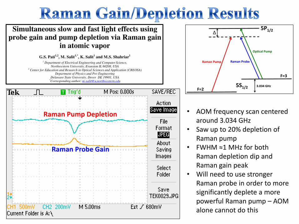
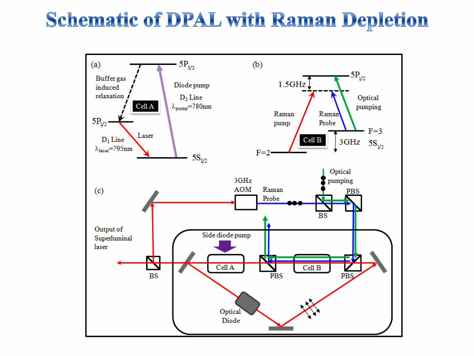
Fig. 5. Energy levels for (a) 795-nm Rb laser to produce broadband gain, (b) Raman
depletion to induce narrowband absorption dip. (c) Schematics of the experimental set-
up to realize a superluminal laser: PBS, polarizing beam splitter; BS, beam splitter;
AOM, acousto-optic modulator. Note that the superluminal laser is the same as the
Raman pump. The scheme shown is for 85
Rb atoms. The broadband gain is produced by side-pumping with a diode laser array.
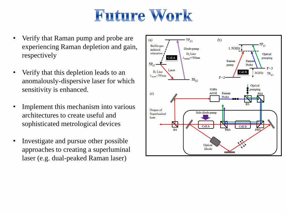
• Verify that Raman pump and probe are
experiencing Raman depletion and gain,
respectively
• Verify that this depletion leads to an
anomalously-dispersive laser for which
sensitivity is enhanced.
• Implement this mechanism into various
architectures to create useful and
sophisticated metrological devices
• Investigate and pursue other possible
approaches to creating a superluminal
laser (e.g. dual-peaked Raman laser)
1
2
than one. Hence, the resonant frequency shift with respect to the length variation decreases compared to the shift in an empty
cavity. For anomalous dispersion (ng<1), the frequency shift is
amplified to be equal to 1/ng times the amount of the shift in the empty
cavity.
In order to determine the actual value of R for an active cavity, we
need first to establish the explicit
dependence of on the lasing
frequency, . To this end, we first
solve Eq. (3.b) in steady state ( )
so that for . Since
is a function of E and , the
solution to the equation yields the
saturated electric field E in steady
state inside the laser cavity as a
function of the lasing frequency .
Let us consider the case in which
the cavity contains a medium with a
narrow absorption as well as a
medium with a broad gain. This configuration creates a gain profile with a dip in the center. The
imaginary part of the susceptibility can then be written as:
(5.a)
Where , (k = e or i). We use the subscript “e” for the “envelope” gain
profile and “i” for the narrower absorption profile .
Using the modified Kramers-Kronig (MKK) relation4 for the saturated susceptibility, we can
then express the real part of the susceptibility as:
(5.b)
Here i ( e) is the Rabi frequency equal to ( ) where ( ) is the dipole moment
associated with the absorbing (amplifying) medium. The gain and the absorption linewidths are
denoted by e and i, respectively. Using the Wigner–Weisskopf modelxxv
for spontaneous
emission, we can define two parameters: and . In terms of these
parameters, the Rabi frequencies can then be expressed as and . The gain
parameters can then be expressed as and , where 0 is the permittivity
Fig. 5. Energy levels for (a) 795-nm Rb laser to produce broadband gain, (b) Raman
depletion to induce narrowband absorption dip. (c) Schematics of the experimental set-
up to realize a superluminal laser: PBS, polarizing beam splitter; BS, beam splitter;
AOM, acousto-optic modulator. Note that the superluminal laser is the same as the
Raman pump. The scheme shown is for 85
Rb atoms. The broadband gain is produced by side-pumping with a diode laser array.