
Radiance Theory - Todor Georgiev - Qualcomm anti symmetric tensor represents the line L. In matrix...
83
Radiance Theory Projective ray geometry. Radiance in geometric optics
Transcript of Radiance Theory - Todor Georgiev - Qualcomm anti symmetric tensor represents the line L. In matrix...
Radiance Theory
Projective ray geometry. Radiance in geometric optics
Presenter
Presentation Notes
This builds the basic mathematical model that we will be using.
Projective space treatment of lightfields
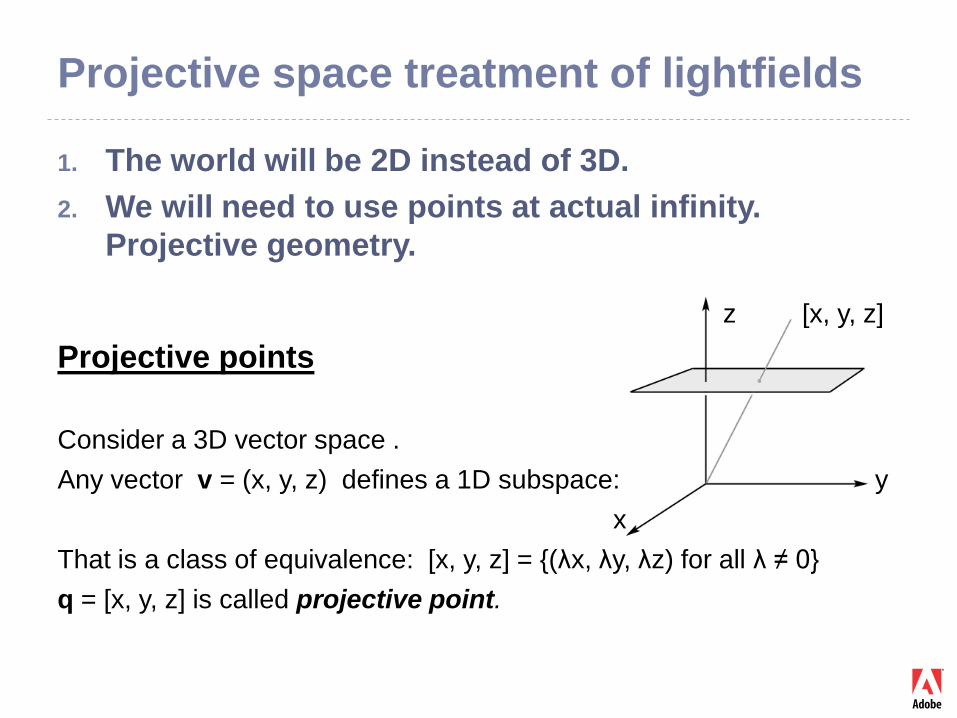
1. The world will be 2D instead of 3D.2. We will need to use points at actual infinity.
Projective geometry.
z [x, y, z]
Projective points
Consider a 3D vector space . Any vector v = (x, y, z) defines a 1D subspace: y
xThat is a class of equivalence: [x, y, z] = {(λx, λy, λz) for all λ ≠ 0}q = [x, y, z] is called projective point.
Projective space treatment of lightfields
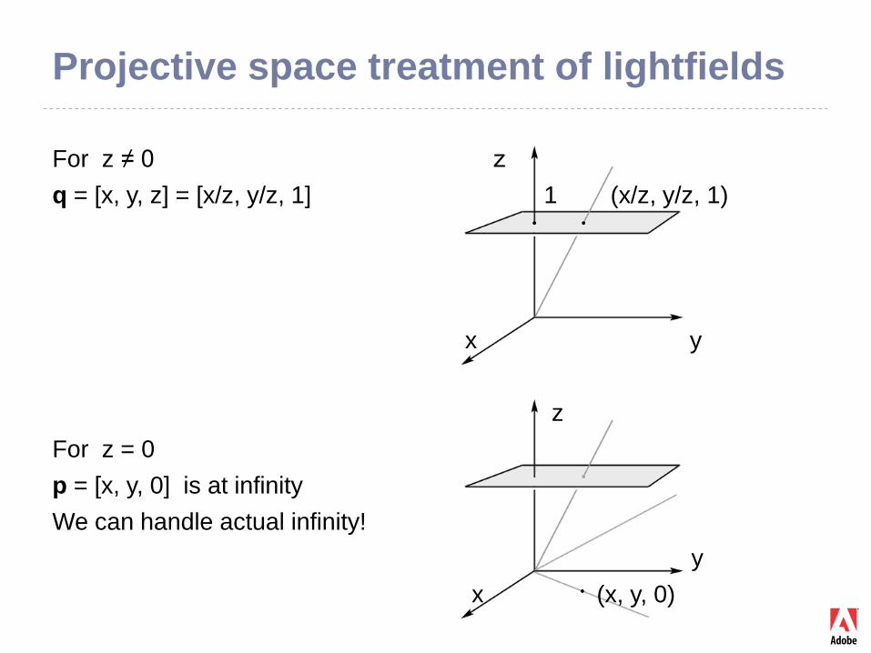
For z ≠ 0 z q = [x, y, z] = [x/z, y/z, 1] 1 (x/z, y/z, 1)
x y
zFor z = 0p = [x, y, 0] is at infinityWe can handle actual infinity!
yx (x, y, 0)
Projective space treatment of lightfields
aΛb
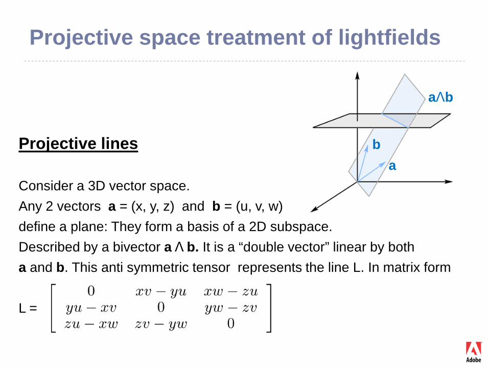
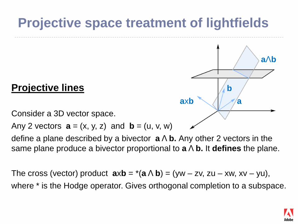
Projective lines ba
Consider a 3D vector space. Any 2 vectors a = (x, y, z) and b = (u, v, w) define a plane: They form a basis of a 2D subspace.Described by a bivector a Λ b. It is a “double vector” linear by both a and b. This anti symmetric tensor represents the line L. In matrix form
L =
Projective space treatment of lightfields
aΛb
Projective lines baxb a
Consider a 3D vector space. Any 2 vectors a = (x, y, z) and b = (u, v, w) define a plane described by a bivector a Λ b. Any other 2 vectors in the same plane produce a bivector proportional to a Λ b. It defines the plane.
The cross (vector) product axb = *(a Λ b) = (yw – zv, zu – xw, xv – yu),where * is the Hodge operator. Gives orthogonal completion to a subspace.
Projective space treatment of lightfields
Summary:
Vectors and bivectors (geometrically lines and planes) represent points and lines in projective space. This includes points at infinity and the line at infinity.
A plane is also represented by the vector orthogonal to it, the cross product.
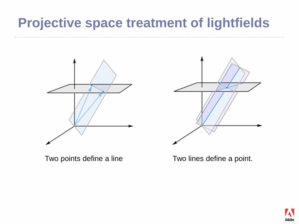
Two points define a line: The bivector a Λ b defines a plane (projective line).
Two lines intersect at a point: The two cross products are two vectors. Their cross product is a vector defining the intersection point projectively.
Projective space treatment of lightfields
Two points define a line Two lines define a point.
Projective space treatment of lightfields
Interpretation
Light rays (as projective lines) can be defined by 2 points: The line is the cross product or the bivector of those 2 points.
Given a point from a ray, the ray is completely defined by direction, i.e. point at infinity. A finite point and a point at infinity define a ray uniquely.
No rays are excluded. No limitation to angle / field of view.
Next we will be using the more popular 2-plane parametrisation that is easier, but cannot handle certain rays.
A true model needs to be 3D projective space.
Ray Transforms
The main laws of geometric optics
Presenter
Presentation Notes
The lightfield (or radiance) is a density function in ray space. Radiance capture, radiance transforms, and projections of the 4D radiance onto a 2D plane to render an image, are the three main building blocks of lightfield photography. Understanding ray transforms is the first step towards understanding radiance transforms.
Two Parameterizations of Rays
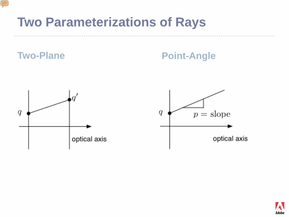
Two-Plane Point-Angle
Presenter
Presentation Notes
There are two popular ways of uniquely defining the coordinates of a ray: Two-plane parameterization (Levoy-Hanrahan). Take two parallel planes. Assume a ray intersects them. We get two 2D intersection points, q and q’. These are used as the 4 coordinates of a ray. (2) Location-angle parametrization (used in most Optics books). Take a plane perpendicular to the optical axis. A ray intersecting that plane is defined by the 2D point of intersection q, and the two angles (slopes) p at which the ray intersects the plane. The location-angle parametrization could be seen as “the differential two-plane parametrization”: Two infinitely close planes are intersected with a ray. The intersection point and the two slopes (derivatives) define the ray uniquely! In this way, two-plane parametrization can be defined at a single point (more convenient and widely used for mathematical derivations). Ref: http://www.cs.umd.edu/class/spring2005/cmsc828v/papers/p31-levoy.pdf http://www.cs.utah.edu/classes/cs5610/handouts/lumigraph.pdf GERRARD A., BURCH J. M.: Introduction to matrix methods in optics. GUILLEMIN V., STERNBERG S.: Symplectic techniques in physics.
Transport Through Space
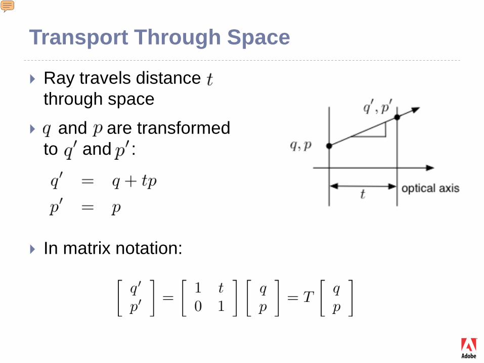
Ray travels distance through space
and are transformed to and :
In matrix notation:
Presenter
Presentation Notes
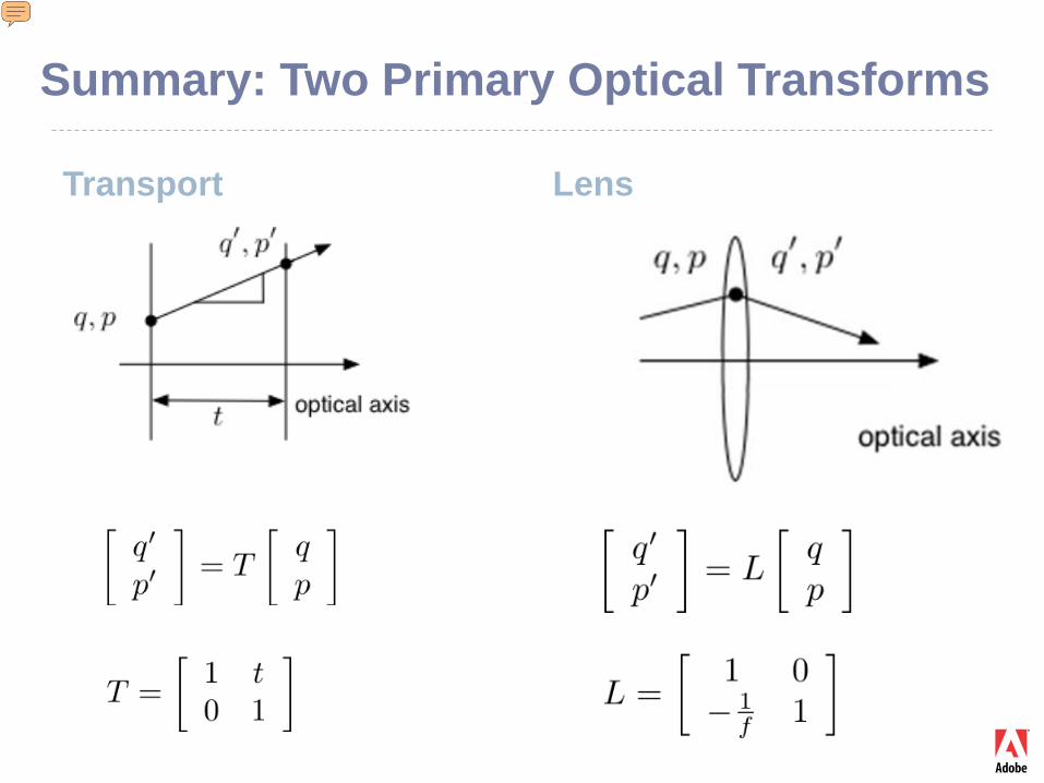
Using Location-angle parametrization, let’s look at how different optical elements transform rays: The first element is “free transport”. Light is traveling in empty space. The ray can be described at one plane, or at another plane. When a ray moves from one plane to another, its position changes, but not its slope. Simple school geometry. Conveniently, we can write this as matrix-vector multiplication and use the vector space formalism for describing rays. What is the optical axis? It is the zero vector of the (q,p) vector space! Note: This is not two-plane parameterization! Remember that (q,p) parameterization is for one plane and then the other plane.
Lens Transformation
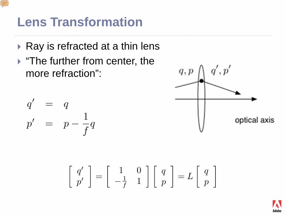
Ray is refracted at a thin lens “The further from center, the
more refraction”:
Presenter
Presentation Notes
A thin lens is defined as an optical element located at one of the above planes perpendicular to the optical axis. By definition, a lens bends the ray, i.e. changes the angle p. The further away from the optical axis the more it bends the ray. This produces the above formulas. Note: The fact that a lens can be approximately implemented as a spherical shaped glass surface is not important for this definition. We avoid implementation details and capture functionality.
Summary: Two Primary Optical Transforms
Transport Lens
Presenter
Presentation Notes
Summary about the two elements. The approach was first introduced by Gauss. The amazing discovery that he made was that all optics can be expressed with combinations of these two elements. In other words, in Gaussian optics (linear ray optics) there is nothing else! Just knowledge of these two elements and matrix multiplication can give us all optics! All facts from lightfield theory can be expressed in such terms and this greatly simplifies the treatment.
Phase Space This is simply the (q, p) space of rays. It is a 4D
vector space with zero vector the optical axis.
Each ray is a 4D point (a vector) in that space.
Any optical device, like a microscope or a telescope, is a matrix that transforms an incoming ray into an outgoing ray.
This matrix can be computed as a product of the optical elements that make up the device.
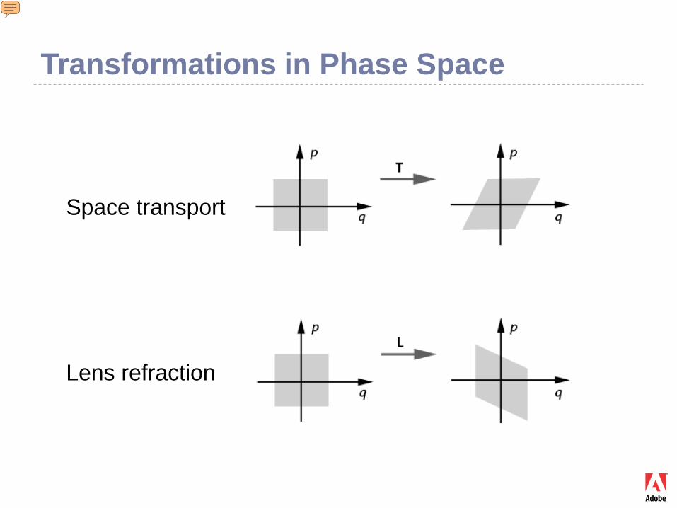
Transformations in Phase Space
Space transport
Lens refraction
Presenter
Presentation Notes
If we consider a number of points in (q, p) and actually perform the multiplications with lens and space transport matrices, we can build the following picture. It shows how “point clouds” or “bundles of rays” are transformed by the two types of optical elements. Note that this is always a shear transform. We will also see that the transform preserves volume, as if the cloud is incompressible fluid. This will be important part of our future considerations in this course.
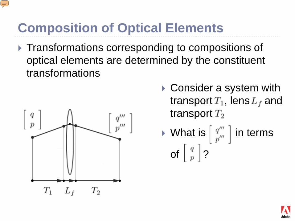
Composition of Optical Elements Transformations corresponding to compositions of
optical elements are determined by the constituent transformations
Consider a system with transport , lens and transport
What is in terms
of ?
Presenter
Presentation Notes
Optical systems are composed from these elements
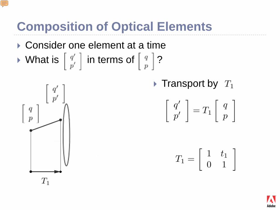
Composition of Optical Elements Consider one element at a time What is in terms of ?
Transport by
Presenter
Presentation Notes
Optical systems are composed from these elements
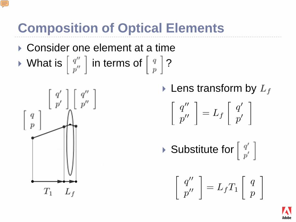
Composition of Optical Elements Consider one element at a time What is in terms of ?
Lens transform by
Substitute for
Presenter
Presentation Notes
Optical systems are composed from these elements
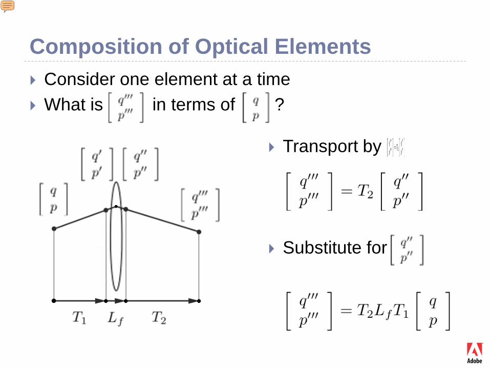
Composition of Optical Elements Consider one element at a time What is in terms of ?
Transport by
Substitute for
Presenter
Presentation Notes
Optical systems are composed from these elements
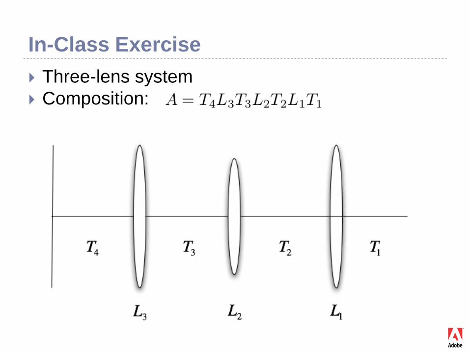
In-Class Exercise Three-lens system Composition:
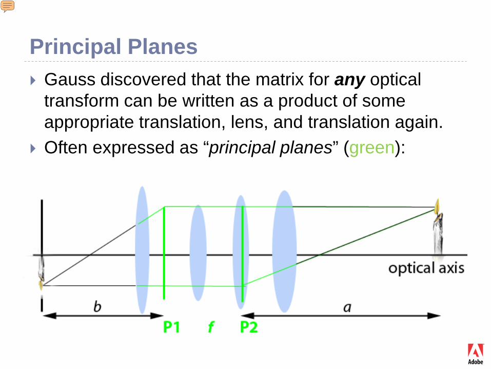
Principal Planes Gauss discovered that the matrix for any optical
transform can be written as a product of some appropriate translation, lens, and translation again.
Often expressed as “principal planes” (green):
Presenter
Presentation Notes
We can decompose any optical system to T L T. This is a statement about the complexity of optical systems. Any optical system is only as complex as a system of one lens and two space translations.
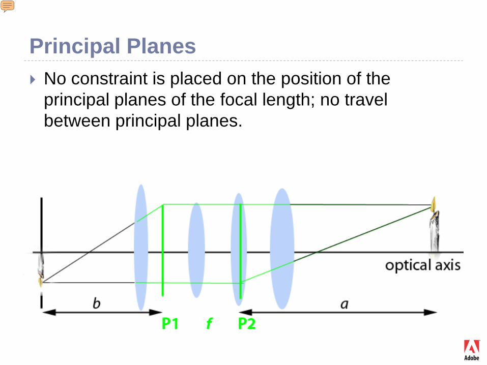
Principal Planes No constraint is placed on the position of the
principal planes of the focal length; no travel between principal planes.
Presenter
Presentation Notes
There are lots of practical uses. For example, in wide-angle lenses a principal plane is placed close to the sensor to create a short focal length. It may be outside the lens system, and at a location where no physical lens can be placed (due to the flipping mirror in an SLR camera). Demo will be shown.
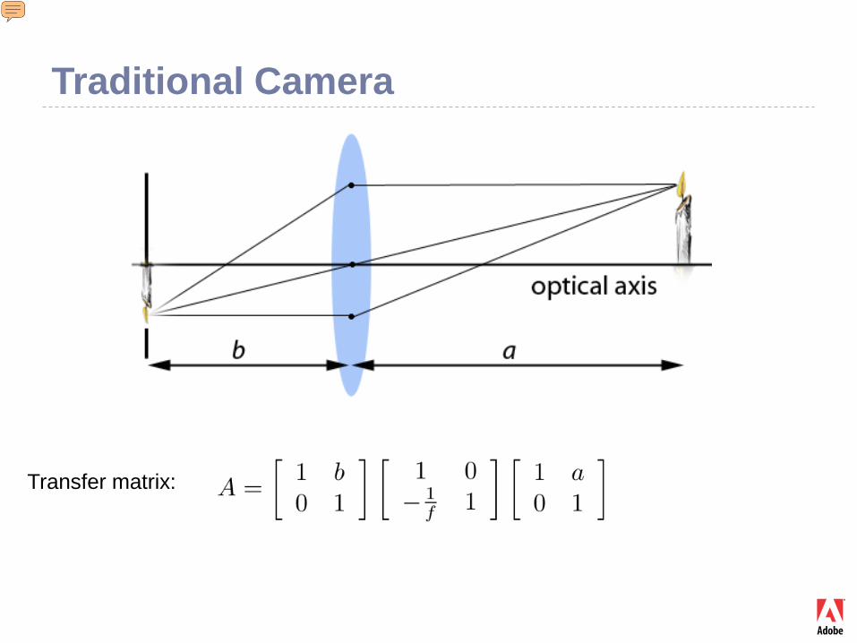
Traditional Camera
Transfer matrix:
Presenter
Presentation Notes
Let’s derive a particular system – a camera. We have a main lens – a distance a in front and a distance b behind. The composite transformation is the product of translation by a, lens, and translation by b.
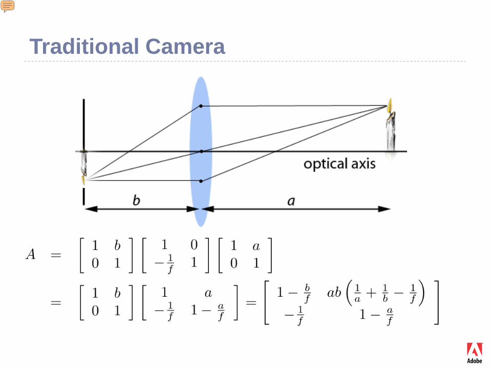
Traditional Camera
Presenter
Presentation Notes
Multiply the matrices.
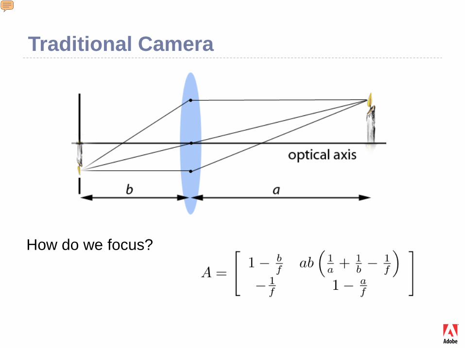
Traditional Camera
How do we focus?
Presenter
Presentation Notes
By making the top right element 0, we require that all rays coming from a given point [but different angles] converge to a single image point. Convergence does not depend on initial angle. This is called focusing. The above condition is met by appropriate values of a and b.
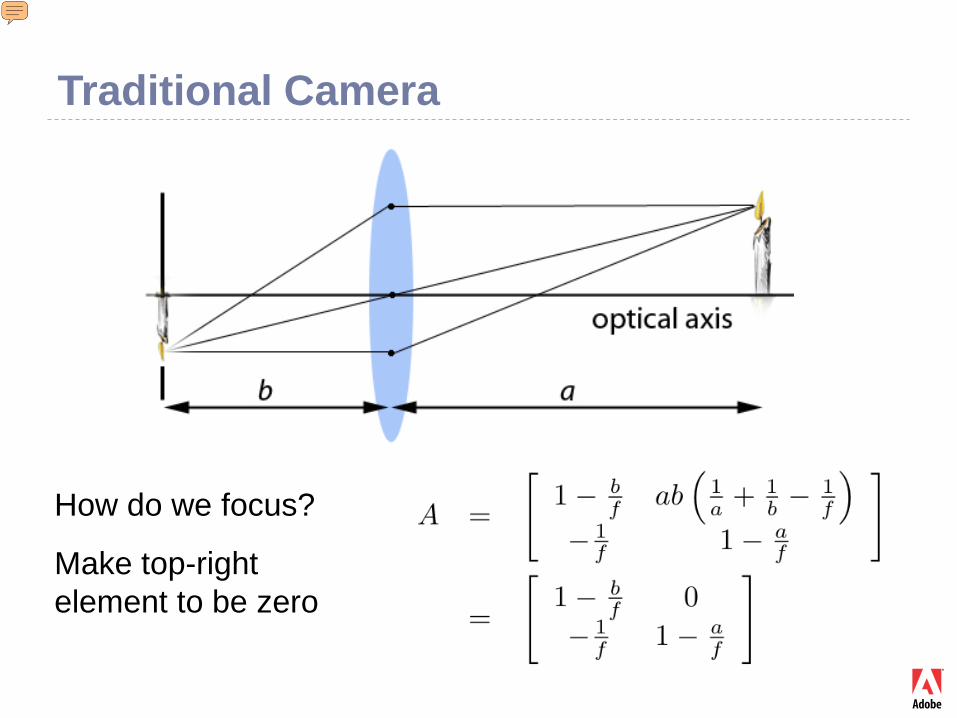
Traditional Camera
How do we focus?
Make top-right element to be zero
Presenter
Presentation Notes
By making the top right element 0, we require that all rays coming from a given point [but different angles] converge to a single image point. Convergence does not depend on initial angle. This is called focusing. The above condition is met by appropriate values of a and b.
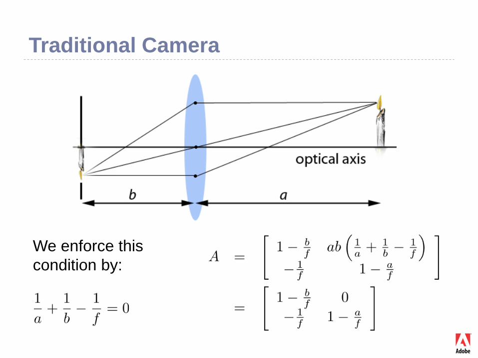
Traditional Camera
We enforce thiscondition by:
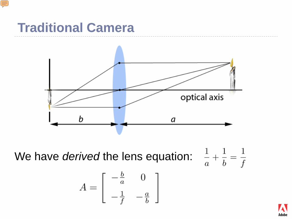
Traditional Camera
We have derived the lens equation:
Presenter
Presentation Notes
This was a derivation of the lens equation, starting from matrix optics. We never assumed the lens equation! The lens equation is equivalent to the condition that the image depends on position, and not on angle. That condition is called focusing.
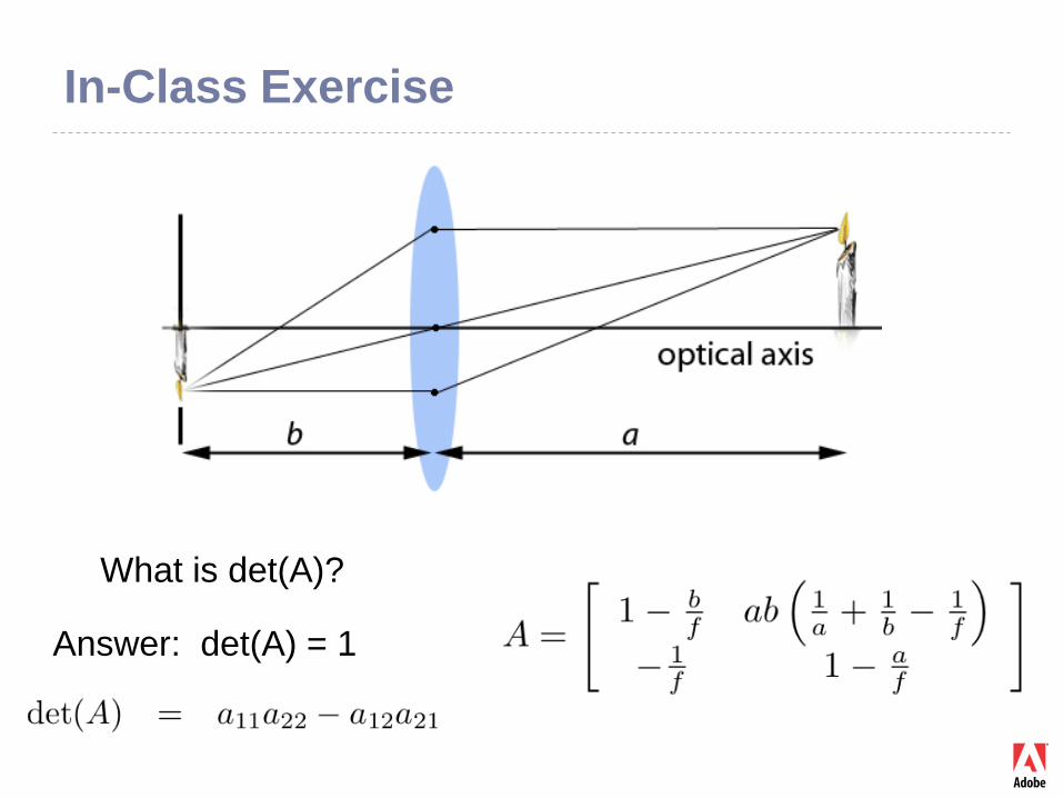
In-Class Exercise
What is det(A)?
Answer: det(A) = 1
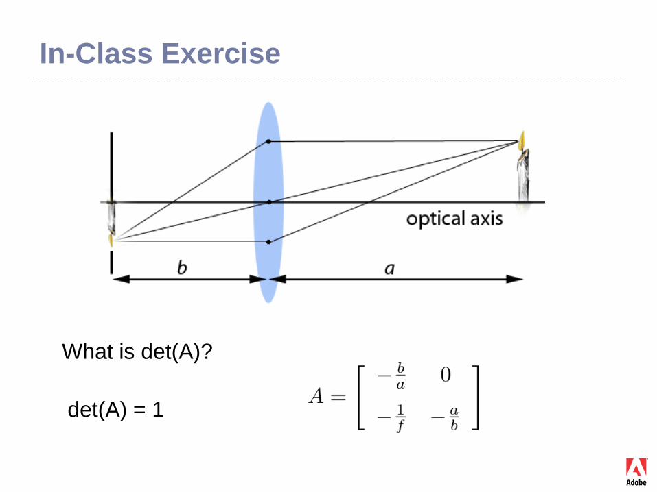
In-Class Exercise
What is det(A)?
det(A) = 1
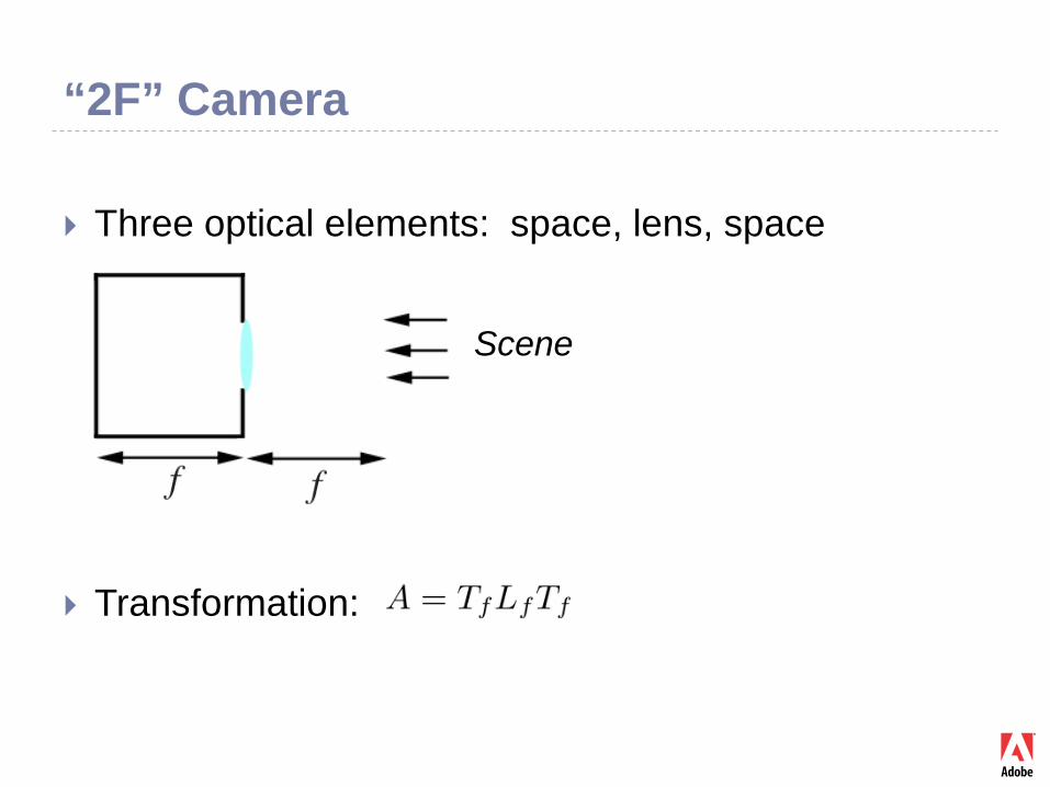
“2F” Camera
Three optical elements: space, lens, space
Transformation:
Scene
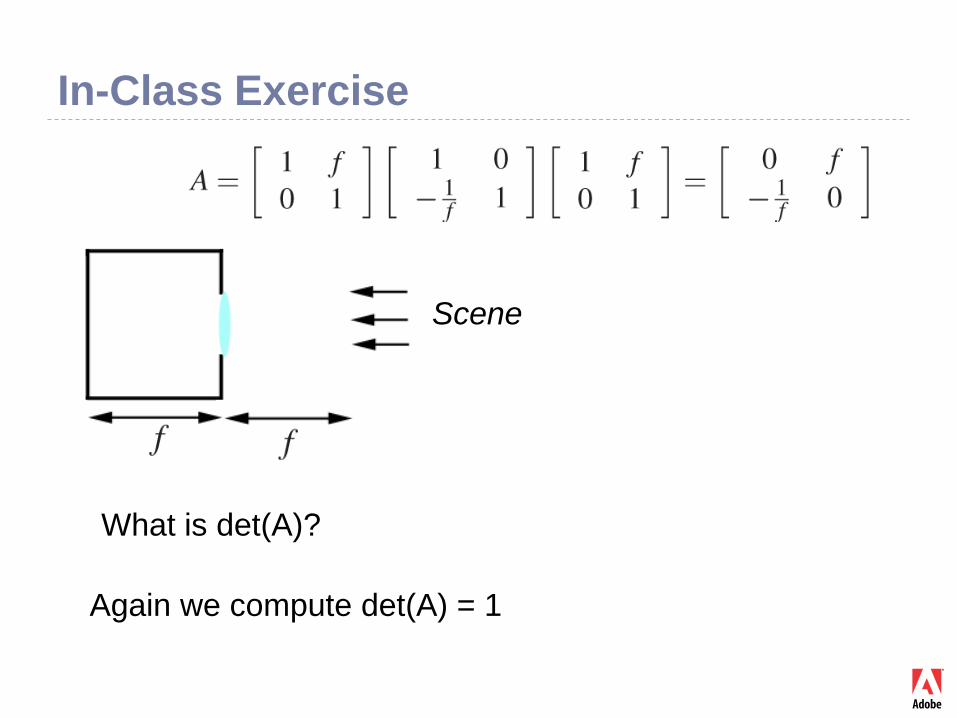
In-Class Exercise
Scene
Again we compute det(A) = 1
What is det(A)?
In-Class Exercise In two different cases (conventional and “2F”
camera) we get the same result: det(A) = 1
Is that always the case?
Hint: Every optical system is a composition of L and T, which both have det = 1
And the determinant of a product is the product of the determinants.
This is an important physical property.
Radiance
Definition and main mathematical properties
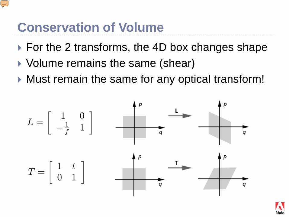
Conservation of Volume For the 2 transforms, the 4D box changes shape Volume remains the same (shear) Must remain the same for any optical transform!
Presenter
Presentation Notes
Det =1 means transformations preserve volume. Here we are considering surface area (2D volume). In the real world the box defines 4D volume in optical phase space (“light field space”). Ref: GERRARD A., BURCH J. M.: Introduction to matrix methods in optics. GUILLEMIN V., STERNBERG S.: Symplectic techniques in physics.
Conservation of Radiance
Radiance is energy density in 4D ray-space Energy is conserved; volume is conserved Radiance = (energy) / ( volume) Radiance is also conserved!
“Radiance is constant along each ray”
Presenter
Presentation Notes
There is another important physical property having to do with radiance itself. Namely, radiance is energy density. We know that energy is conserved. And since the volume is conserved, radiance is conserved!
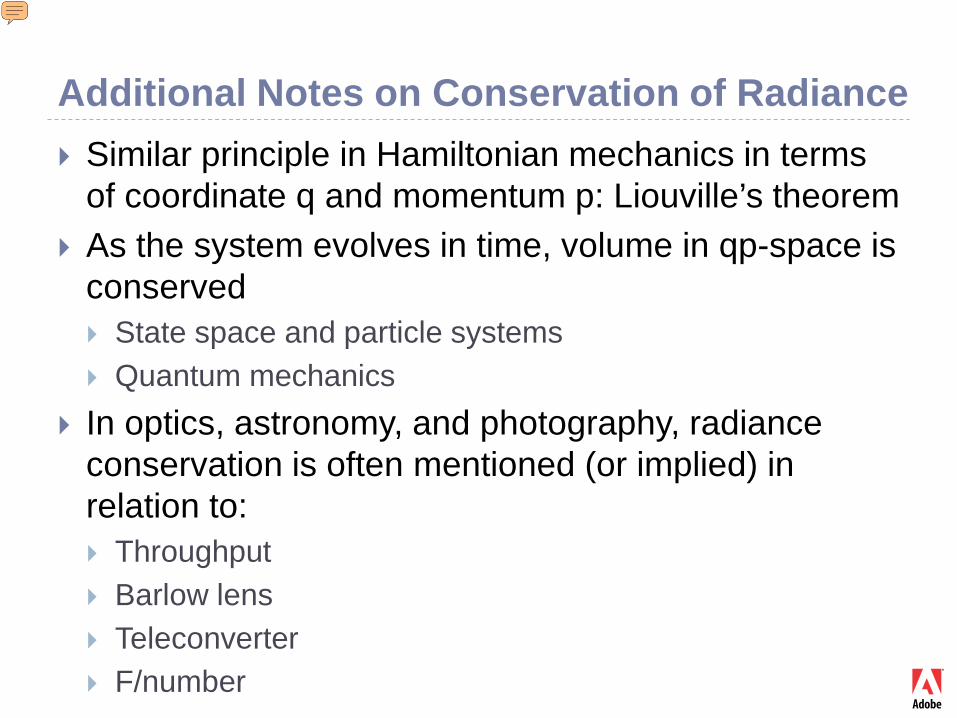
Additional Notes on Conservation of Radiance Similar principle in Hamiltonian mechanics in terms
of coordinate q and momentum p: Liouville’s theorem As the system evolves in time, volume in qp-space is
conserved State space and particle systems Quantum mechanics
In optics, astronomy, and photography, radiance conservation is often mentioned (or implied) in relation to: Throughput Barlow lens Teleconverter F/number
Presenter
Presentation Notes
(1) The relation to quantum mechanics can be illustrated with the uncertainty principle delta q * delta p > h. “Quanta” or boxes of volume h in qp-space. A lightfield camera is already a quantum device doing the best possible measurement of radiance according to quantum mechanics. This is related to matching the F/numbers of main lens and microlenses. Ref: GUILLEMIN V., STERNBERG S.: Symplectic techniques in physics. http://en.wikipedia.org/wiki/Hamiltonian_mechanics http://en.wikipedia.org/wiki/Liouville's_theorem_(Hamiltonian)
Additional Notes on Conservation of Radiance
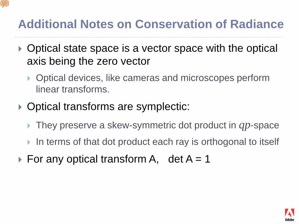
Optical state space is a vector space with the optical axis being the zero vector Optical devices, like cameras and microscopes perform
linear transforms.
Optical transforms are symplectic:
They preserve a skew-symmetric dot product in qp-space
In terms of that dot product each ray is orthogonal to itself
For any optical transform A, det A = 1
Presenter
Presentation Notes
(3) Lightfield cameras do not have this constraint of optical axis, and they work in affine space, not vector space. (4) is related to volume conservation in ray space qp. Ref: GUILLEMIN V., STERNBERG S.: Symplectic techniques in physics.

Radiance Transforms Optical elements transform rays
They also transform radiance
Points in ray space
Radiance before optical transform
Radiance after optical transform
Presenter
Presentation Notes
This lets us describe how radiance is transformed by optical elements. So far we have only been talking about how rays are transformed. But knowing how rays are transformed and knowing that radiance is conserved, we can describe how radiance is transformed in terms of how the rays are transformed. Radiance r’(x) is same as the radiance r at the ray that is mapped to x. This is simply radiance conservation!
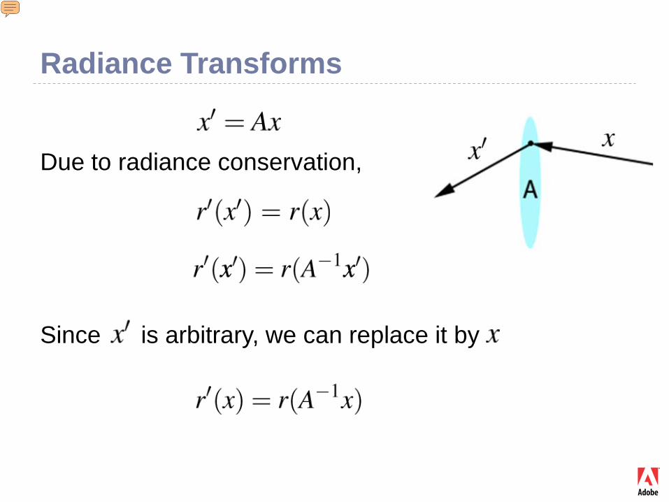
Radiance Transforms
Due to radiance conservation,
Since is arbitrary, we can replace it by
Presenter
Presentation Notes
It doesn’t matter if a variable is denoted x or x’ as long as it is the same everywhere in the equation.
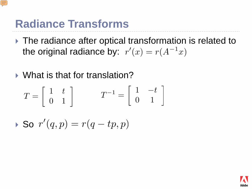
Radiance Transforms The radiance after optical transformation is related to
the original radiance by:
What is that for translation?
So
Presenter
Presentation Notes
Radiance r’(x) is same as the radiance r at the ray that is mapped to x. This is simply radiance conservation!
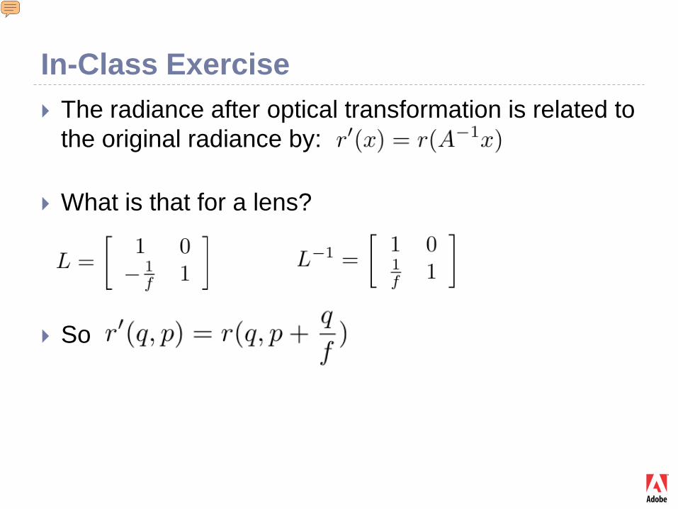
In-Class Exercise The radiance after optical transformation is related to
the original radiance by:
What is that for a lens?
So
Presenter
Presentation Notes
Radiance r’(x) is same as the radiance r at the ray that is mapped to x. This is simply radiance conservation!
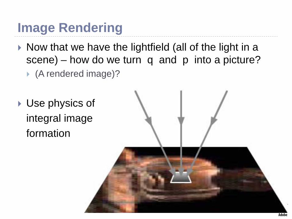
Image Rendering Now that we have the lightfield (all of the light in a
scene) – how do we turn q and p into a picture? (A rendered image)?
Use physics ofintegral imageformation
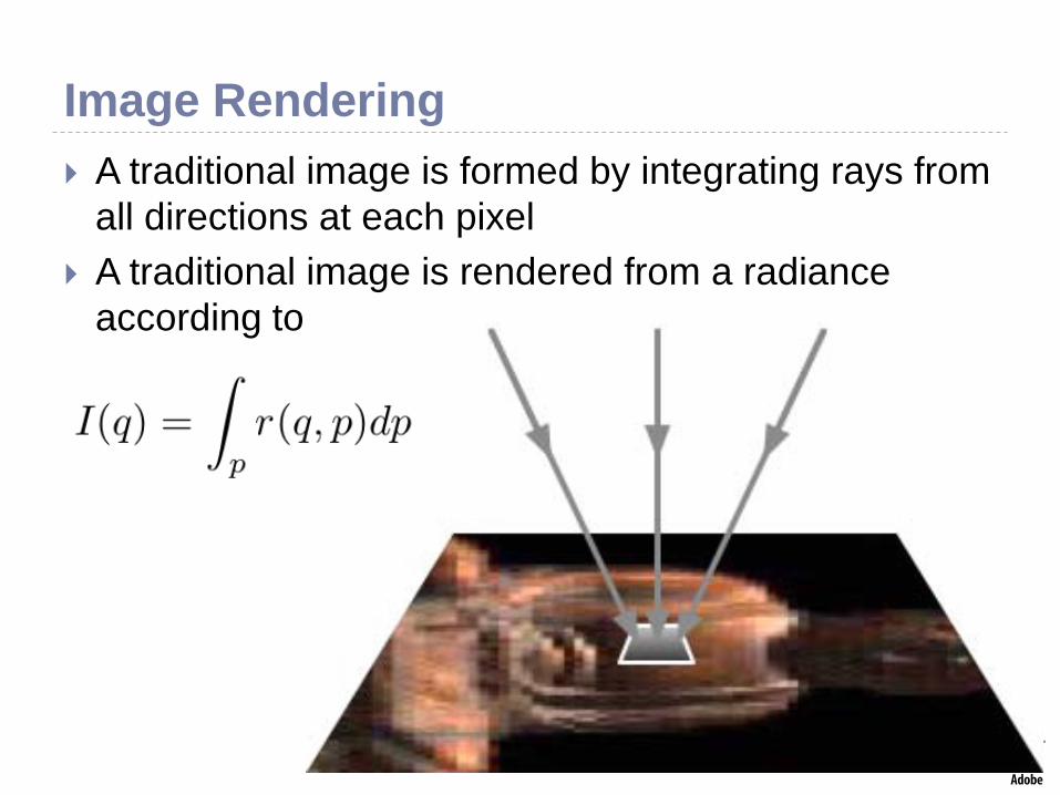
Image Rendering A traditional image is formed by integrating rays from
all directions at each pixel A traditional image is rendered from a radiance
according to
Radiance Capture (Cameras)
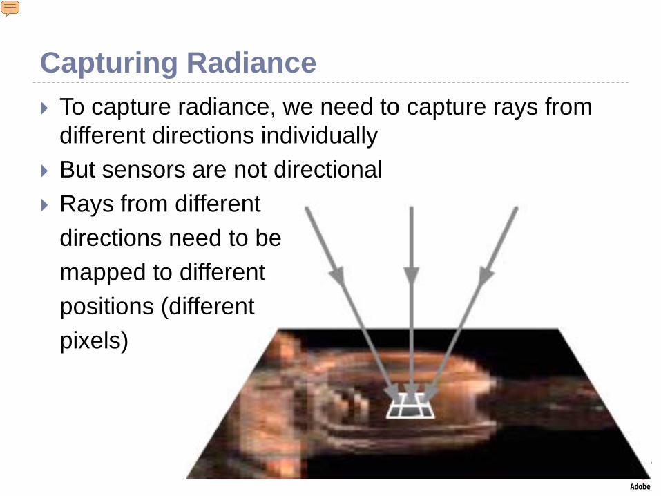
Capturing Radiance To capture radiance, we need to capture rays from
different directions individually But sensors are not directional Rays from different
directions need to bemapped to differentpositions (differentpixels)
Presenter
Presentation Notes
Earlier, we made the intuitive statement that we need to capture rays from different directions individually. How do we do that? Sensors themselves are not directional, so we need to somehow separate out rays from different directions and put them at different positions.
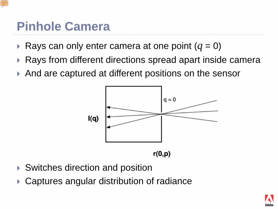
Pinhole Camera Rays can only enter camera at one point (q = 0) Rays from different directions spread apart inside camera And are captured at different positions on the sensor
Switches direction and position Captures angular distribution of radiance
Presenter
Presentation Notes
The pinhole camera is the simplest way to separate rays from different directions
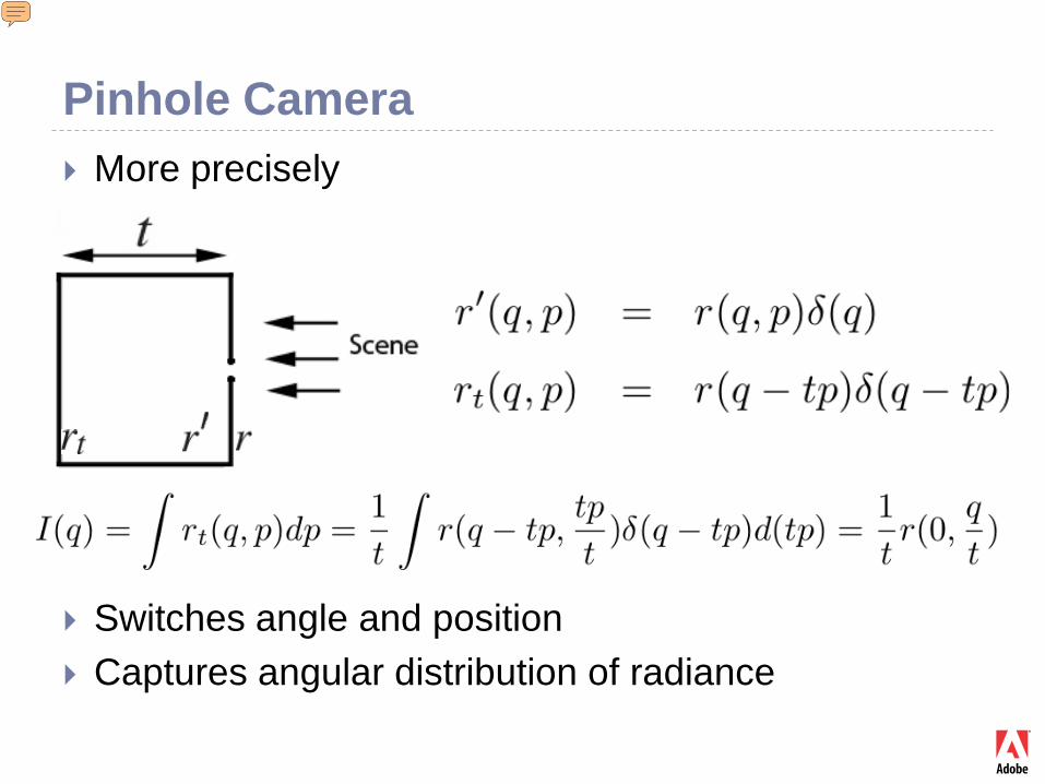
Pinhole Camera More precisely
Switches angle and position Captures angular distribution of radiance
Presenter
Presentation Notes
Nontrivial derivation of pinhole camera, demonstrating how our mathematical method works.
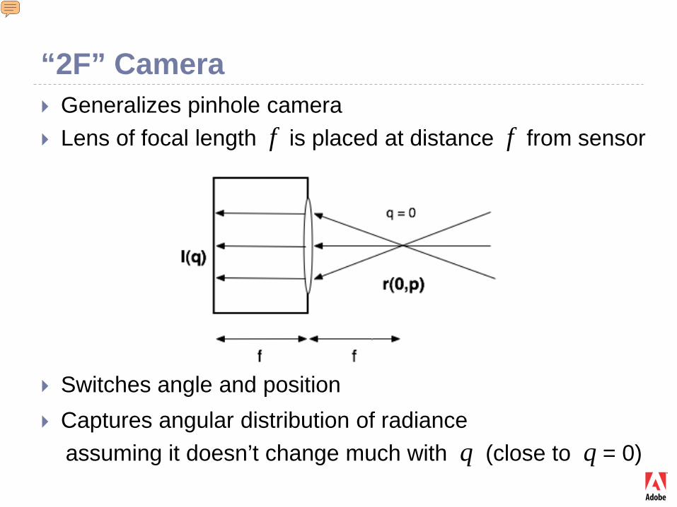
“2F” Camera Generalizes pinhole camera Lens of focal length f is placed at distance f from sensor
Switches angle and position Captures angular distribution of radiance
assuming it doesn’t change much with q (close to q = 0)
Presenter
Presentation Notes
Another way to separate rays from different directions
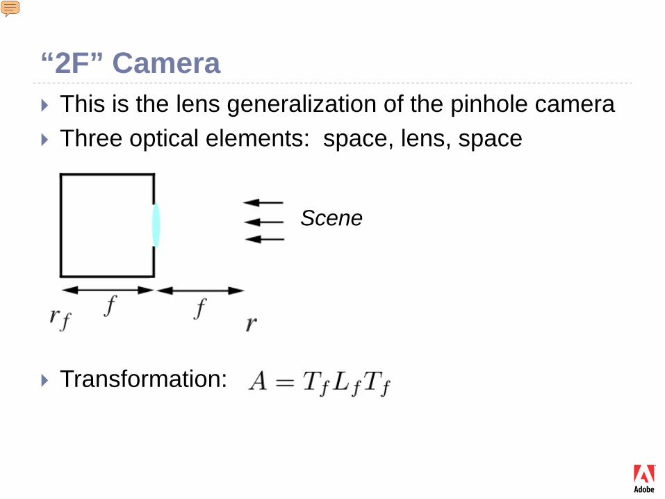
“2F” Camera This is the lens generalization of the pinhole camera Three optical elements: space, lens, space
Transformation:
Scene
Presenter
Presentation Notes
The lens improvement of the pinhole camera. This analysis can be used to understand space multiplexing in Lippmann’s (or Plenoptic) camera. It contains an array of 2F cameras at the image plane.
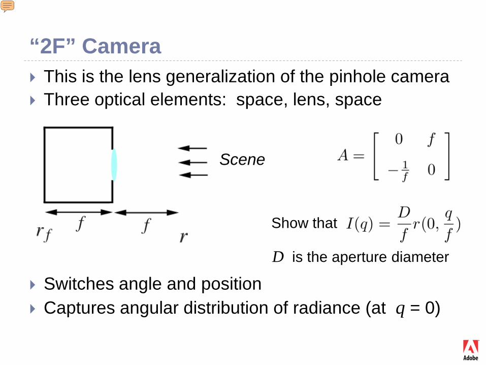
“2F” Camera This is the lens generalization of the pinhole camera Three optical elements: space, lens, space
Switches angle and position Captures angular distribution of radiance (at q = 0)
Show that
D is the aperture diameter
Scene
Presenter
Presentation Notes
The lens improvement of the pinhole camera. This analysis can be used to understand space multiplexing in Lippmann’s (or Plenoptic) camera. It contains an array of 2F cameras at the image plane.
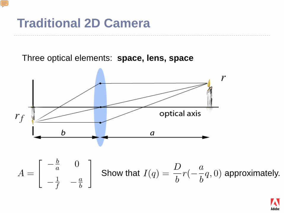
Traditional 2D Camera
Three optical elements: space, lens, space
Show that approximately.
Presenter
Presentation Notes
Note how different this is from the pinhole or 2F camera. The traditional camera literally “touches the surface” of the object it photographs. (The first camera element is empty space!) It does not switch position and angle like the pinhole camera, but directly samples the radiance at the observed surface. Note the coefficient D/b which is the inverse F/number.
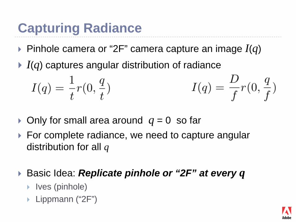
Capturing Radiance Pinhole camera or “2F” camera capture an image I(q) I(q) captures angular distribution of radiance
Only for small area around q = 0 so far For complete radiance, we need to capture angular
distribution for all q
Basic Idea: Replicate pinhole or “2F” at every q Ives (pinhole) Lippmann (“2F”)
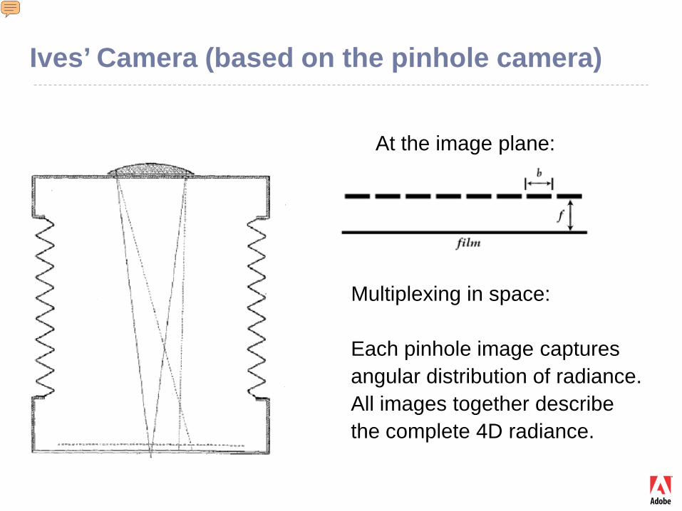
Ives’ Camera (based on the pinhole camera)
At the image plane:
Multiplexing in space:
Each pinhole image capturesangular distribution of radiance.All images together describethe complete 4D radiance.
Presenter
Presentation Notes
Each pinhole microcamera captures pure angular information about the radiance at the image plane. The location of the pinhole is used as the spatial information. http://www.google.com/patents?id=ouBYAAAAEBAJ&printsec=abstract&zoom=4&dq=ives+patents+725,567#v=onepage&q=&f=false
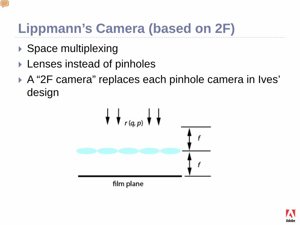
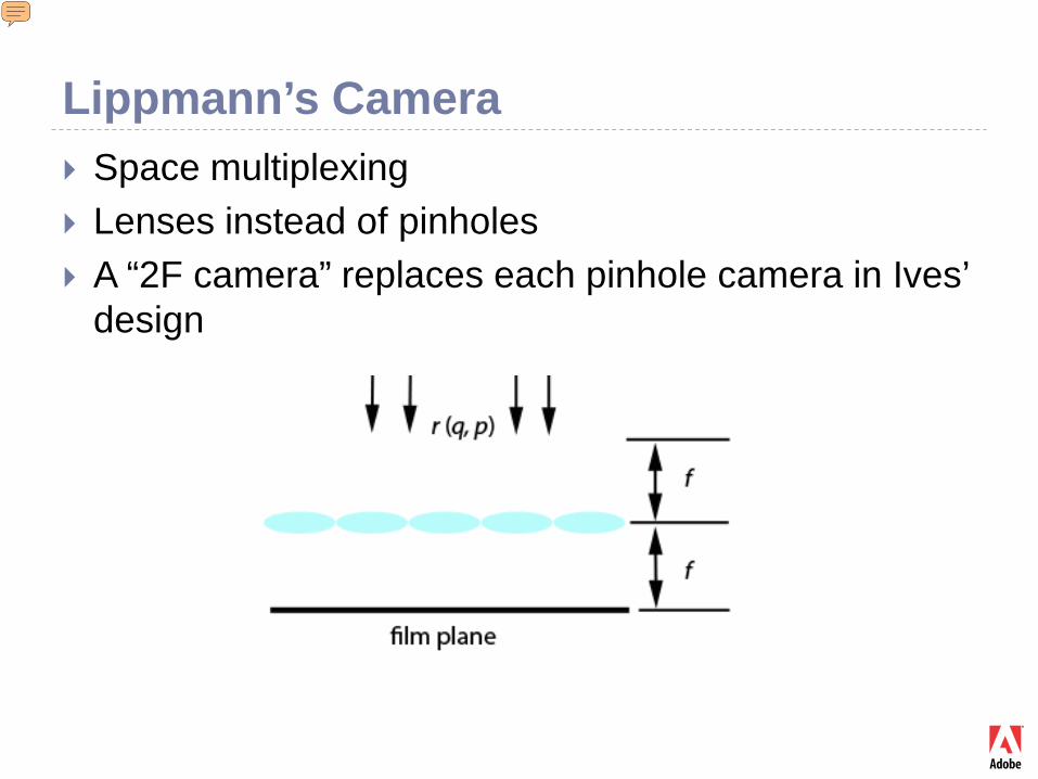
Lippmann’s Camera (based on 2F) Space multiplexing Lenses instead of pinholes A “2F camera” replaces each pinhole camera in Ives’
design
Presenter
Presentation Notes
Note the relation to the Plenoptic camera. Analysis based on 2F camera. Each microlens captures pure angular information. The location of the microlens is used as the spatial information. Ref: http://www.tgeorgiev.net/IntegralView.pdf http://www.tgeorgiev.net/Radiance/
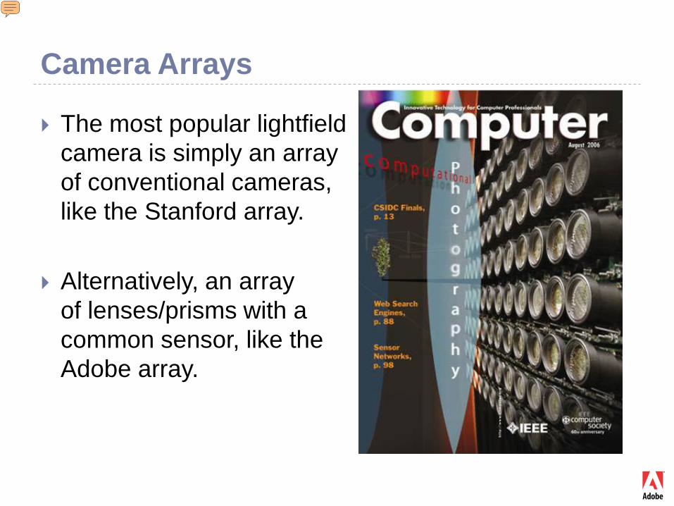
Camera Arrays
The most popular lightfieldcamera is simply an array of conventional cameras, like the Stanford array.
Alternatively, an array of lenses/prisms with a common sensor, like the Adobe array.
Presenter
Presentation Notes
Ref: http://graphics.stanford.edu/papers/CameraArray/ http://www.tgeorgiev.net/Spatioangular.pdf
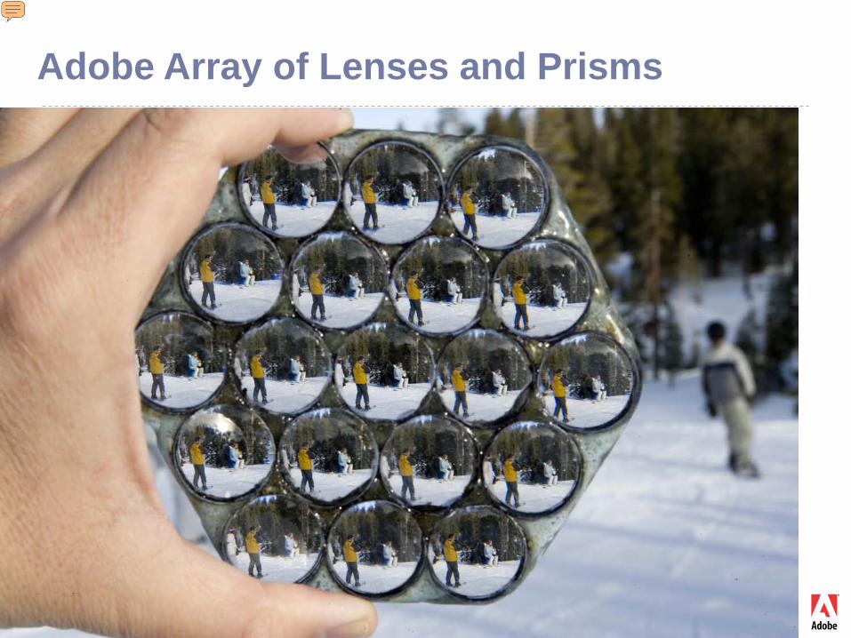
Adobe Array of Lenses and Prisms
Presenter
Presentation Notes
It’s clear that different cameras or different lenses provide different points of view. Ref: http://www.tgeorgiev.net/Spatioangular.pdf
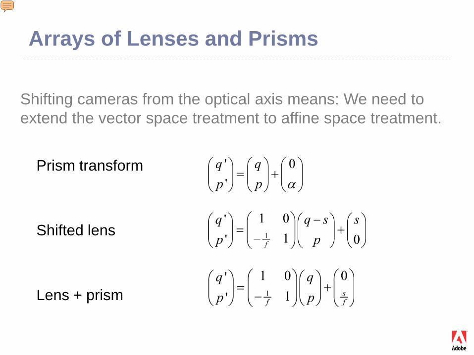
Arrays of Lenses and Prisms
Prism transform
Shifted lens
Lens + prism
Shifting cameras from the optical axis means: We need to extend the vector space treatment to affine space treatment.
Presenter
Presentation Notes
Shifting the camera is equivalent to adding a prism. Lightfield/plenoptic cameras are based on this principle. Gaussian optics is extended to affine optics by adding shifts/prisms. This increases our power to full 3D capture! http://www.tgeorgiev.net/Spatioangular.pdf
Radiance in the Frequency Domain
In the frequency domain, the two optical elements switch places:
lens becomes space; space becomes lens
Presenter
Presentation Notes
Break?
Radiance Transforms (Frequency Domain) Converting radiance into frequency representation
gives us a new tool for analysis, and new power. A pixel no longer stands by itself, representing a
point in one single image / slice in 4D radiance. In the frequency domain one pixel can represent
multiple images at the same time. Those images are slices of the 4D radiance, but now
in the frequency domain. By optically combining multiple frequencies, we
achieve new and more efficient use of the sensor.
Radiance Transforms (Frequency Domain)
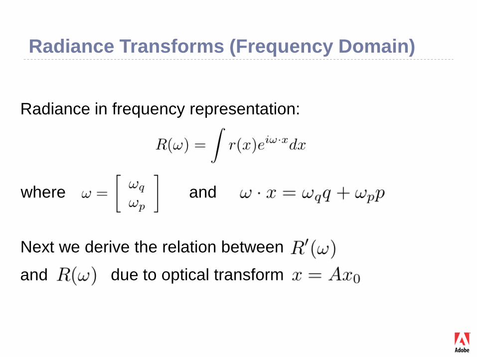
Radiance in frequency representation:
where and
Next we derive the relation between
and due to optical transform
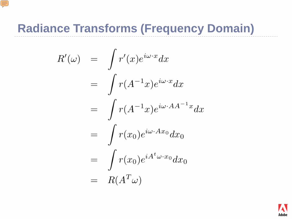
Radiance Transforms (Frequency Domain)
Presenter
Presentation Notes
Important derivation of the general transform in frequency domain.
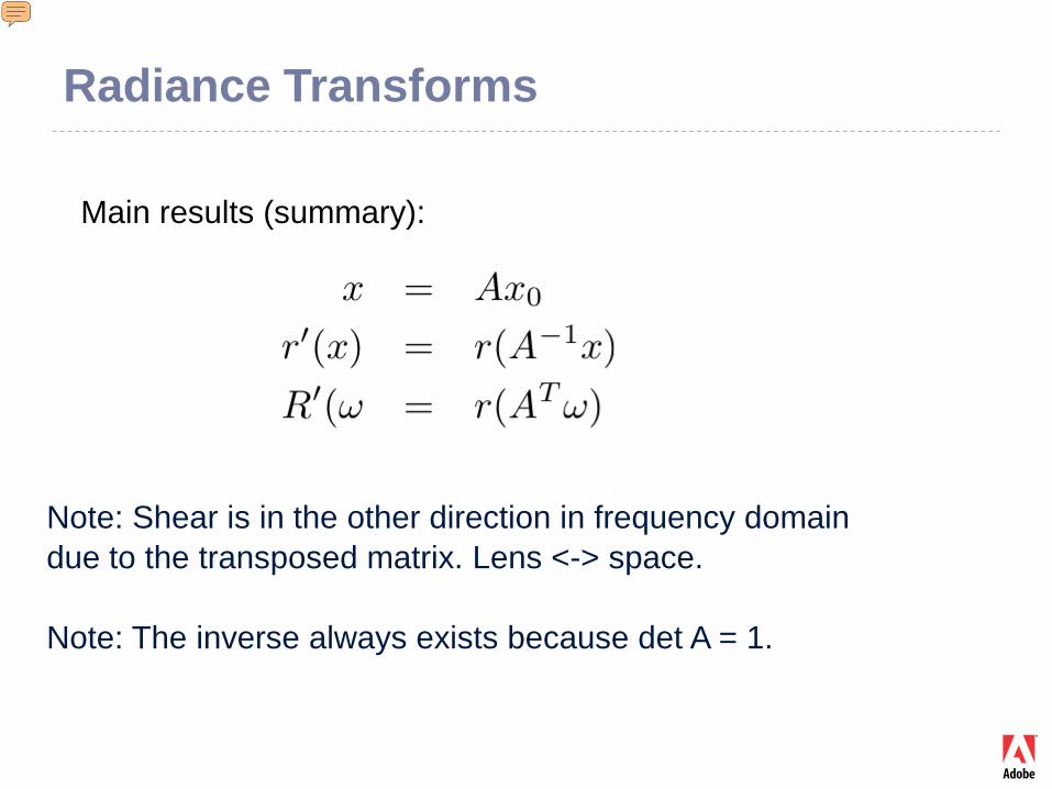
Radiance Transforms
Main results (summary):
Note: Shear is in the other direction in frequency domain due to the transposed matrix. Lens <-> space.
Note: The inverse always exists because det A = 1.
Presenter
Presentation Notes
Add picture here?
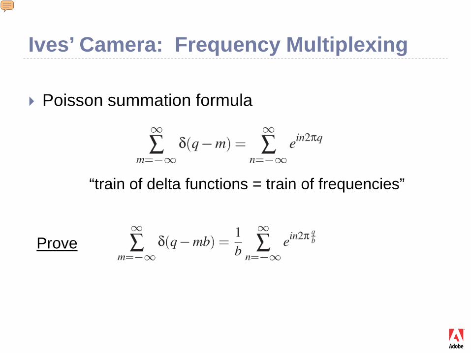
Ives’ Camera: Frequency Multiplexing
Poisson summation formula
Prove
“train of delta functions = train of frequencies”
Presenter
Presentation Notes
This formula should be familiar from derivations of sampling and antialiasing methods.
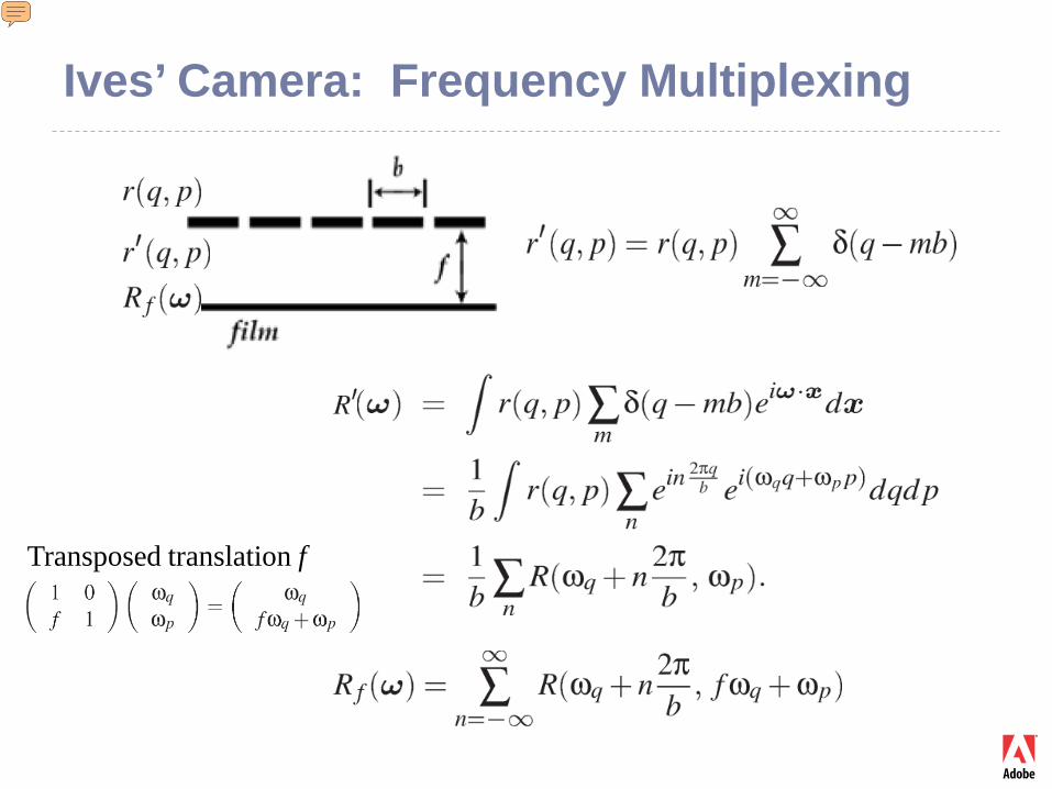
Transposed translation f
Ives’ Camera: Frequency Multiplexing
Presenter
Presentation Notes
Ref: http://www.tgeorgiev.net/Radiance/
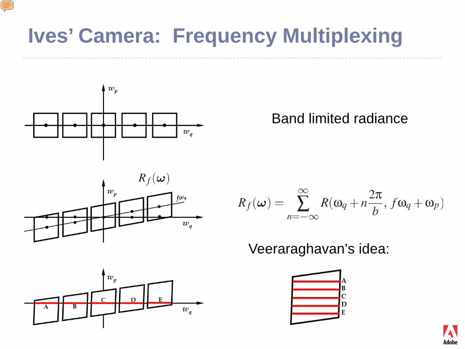
Band limited radiance
Veeraraghavan’s idea:
Ives’ Camera: Frequency Multiplexing
Presenter
Presentation Notes
This “heterodyning” idea is an example of good science. It clearly stands out as one of the best ideas in the 100-year history of lightfield capture / integral photography. Ref: http://www.merl.com/people/raskar/Mask/
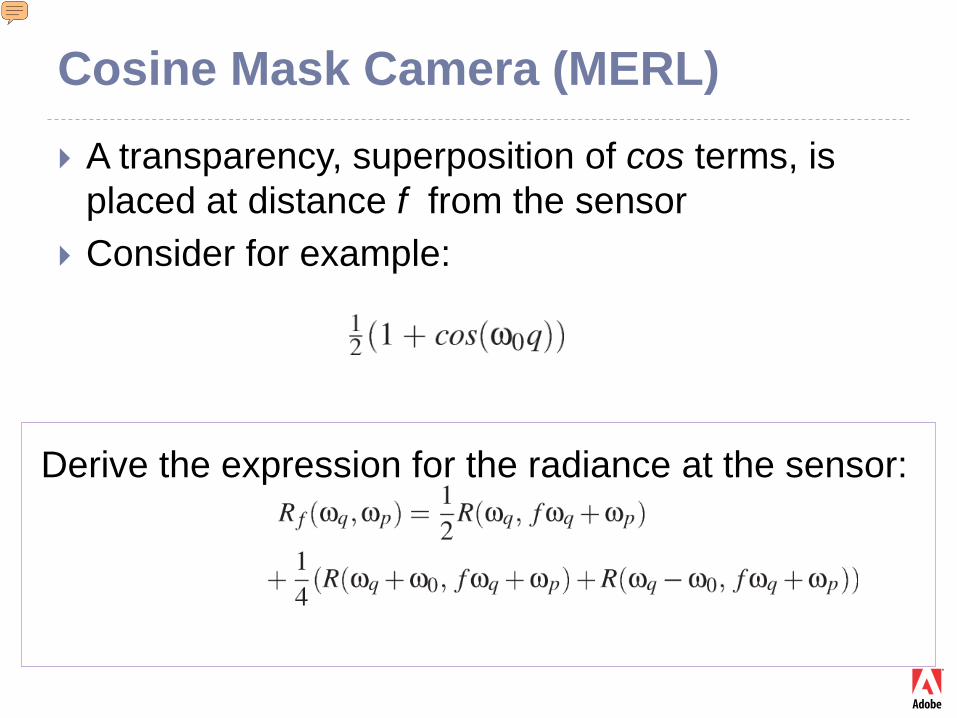
Cosine Mask Camera (MERL)
A transparency, superposition of cos terms, is placed at distance f from the sensor
Consider for example:
Derive the expression for the radiance at the sensor:
Presenter
Presentation Notes
One of the great ideas in the history of lightfield photography.
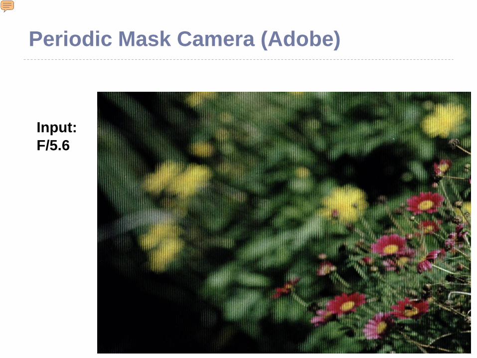
Periodic Mask Camera (Adobe)
Input:F/5.6
Presenter
Presentation Notes
See video: http://www.tgeorgiev.net/RadianceCameras/Additional/F5.6.gif
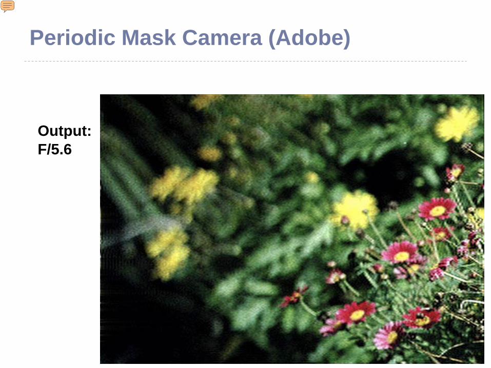
Output:F/5.6
Periodic Mask Camera (Adobe)
Presenter
Presentation Notes
See video: http://www.tgeorgiev.net/RadianceCameras/Additional/F5.6.gif
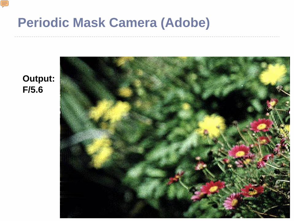
Output:F/5.6
Periodic Mask Camera (Adobe)
Presenter
Presentation Notes
See video: http://www.tgeorgiev.net/RadianceCameras/Additional/F5.6.gif
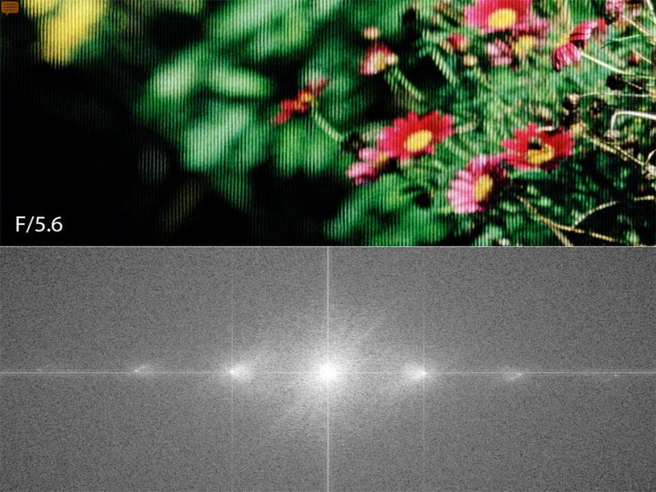
Ives’ camera: Multiplexing in frequency
Presenter
Presentation Notes
Closer than optimal. It works but cannot sample the whole range of angular frequencies.
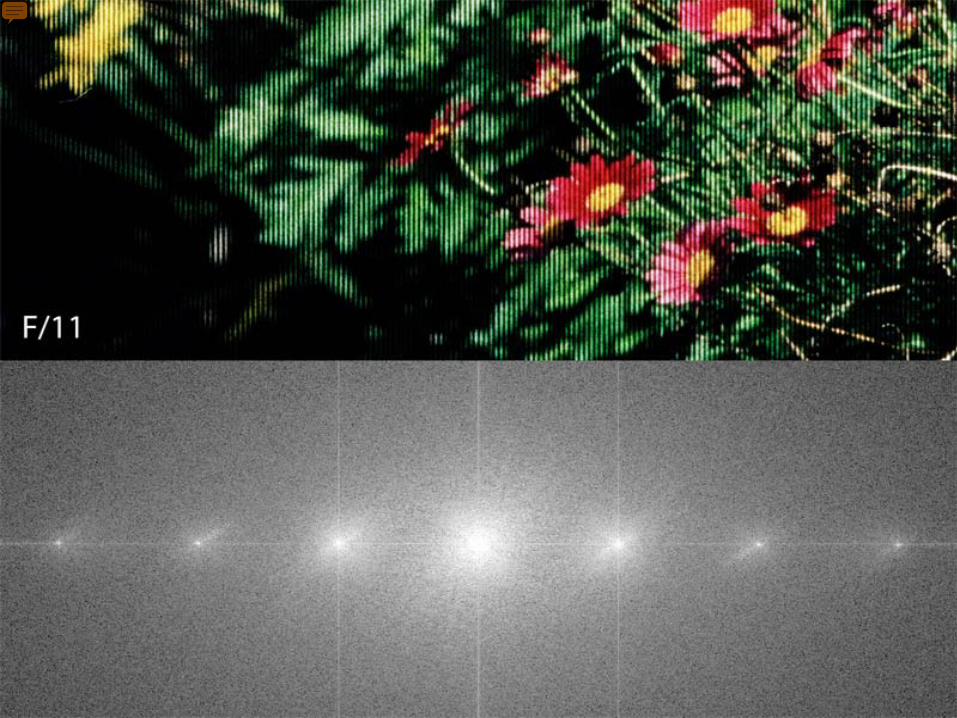
Ives’ camera: Multiplexing in frequency
Presenter
Presentation Notes
Just the right distance. See video: http://www.tgeorgiev.net/RadianceCameras/Additional/F5.6.gif
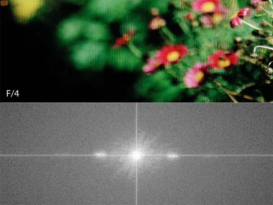
Ives’ camera: Multiplexing in frequency
Presenter
Presentation Notes
Big distance and tilt, not able to pick up high angular frequency copies of the spectrum. Video: http://www.tgeorgiev.net/RadianceCameras/Additional/F4.gif
Output:F/4
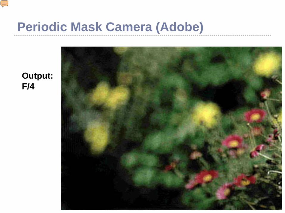
Periodic Mask Camera (Adobe)
Presenter
Presentation Notes
It is clear that F/numbers must match not only for microlens (Lippmann) type cameras, but also for mask-based (heterodyning) cameras. http://www.tgeorgiev.net/RadianceCameras/Additional/F5.6.gif http://www.tgeorgiev.net/RadianceCameras/Additional/F4.gif
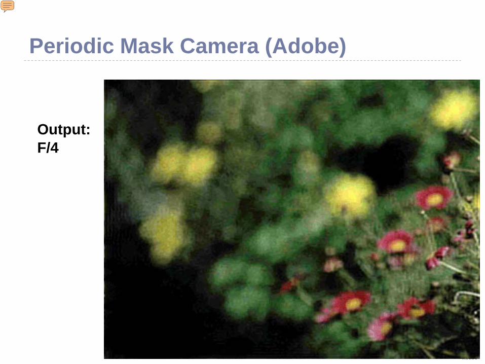
Output:F/4
Periodic Mask Camera (Adobe)
Presenter
Presentation Notes
It is clear that F/numbers must match not only for microlens (Lippmann) type cameras, but also for mask-based (heterodyning) cameras.
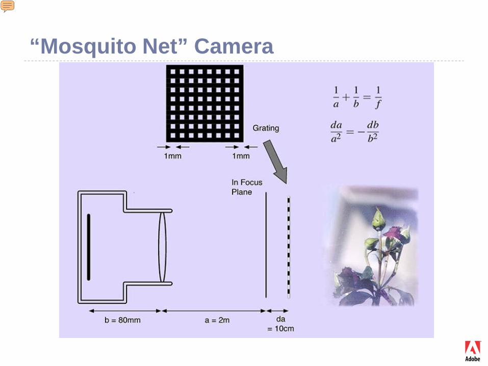
“Mosquito Net” Camera
Presenter
Presentation Notes
Mask placed outside the camera. Camera focused slightly closer than the mask. Easy to make. http://www.tgeorgiev.net/FrequencyMultiplexing.pdf
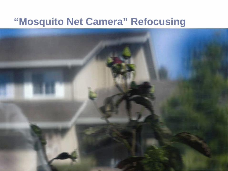
“Mosquito Net Camera” Refocusing
Lippmann’s Camera Space multiplexing Lenses instead of pinholes A “2F camera” replaces each pinhole camera in Ives’
design
Presenter
Presentation Notes
Note the relation to the Plenoptic camera. Analysis based on 2F and different from the traditional view: Ref: http://www.tgeorgiev.net/IntegralView.pdf http://www.tgeorgiev.net/Radiance/
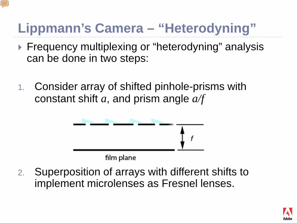
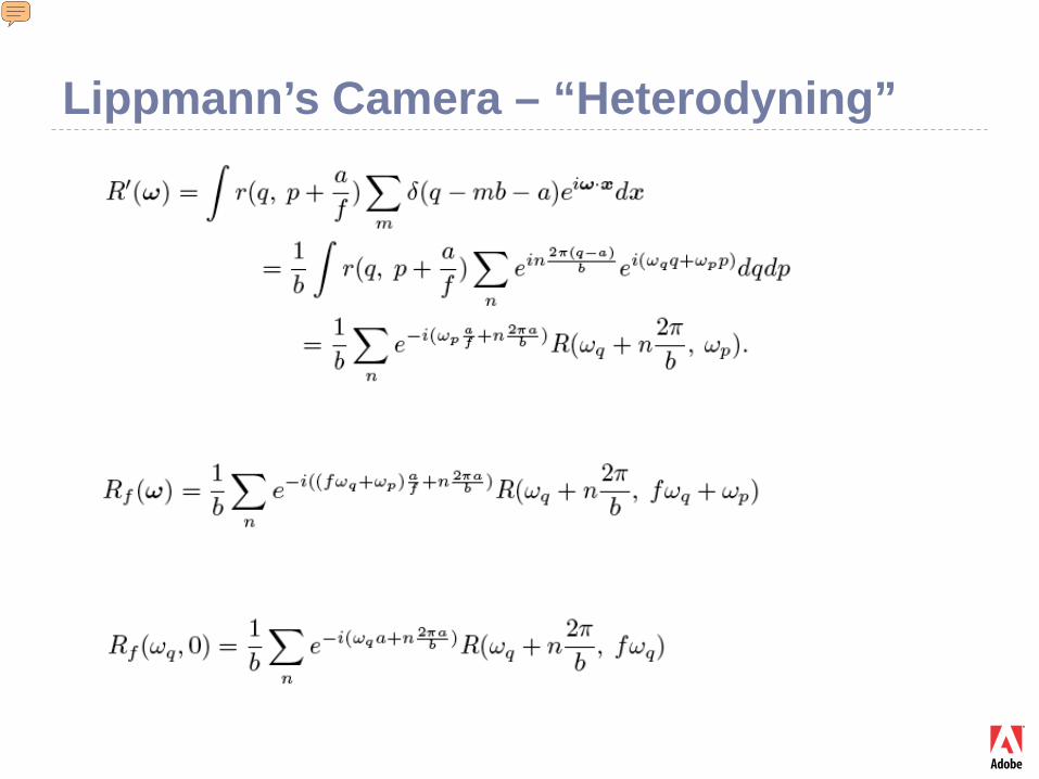
Lippmann’s Camera – “Heterodyning” Frequency multiplexing or “heterodyning” analysis
can be done in two steps:
1. Consider array of shifted pinhole-prisms with constant shift a, and prism angle a/f
2. Superposition of arrays with different shifts to implement microlenses as Fresnel lenses.
Presenter
Presentation Notes
We will discuss only (1). Ref: http://www.tgeorgiev.net/Radiance/
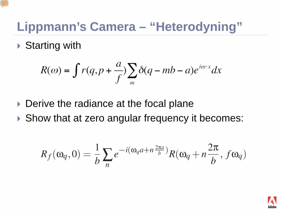
Lippmann’s Camera – “Heterodyning” Starting with
Derive the radiance at the focal plane Show that at zero angular frequency it becomes:
Presenter
Presentation Notes
The easy way to see that this works is to consider small a. Ref: http://www.tgeorgiev.net/Radiance/
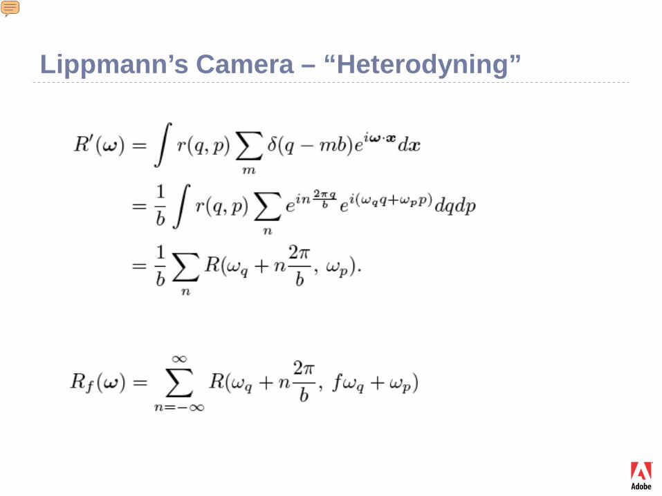
Lippmann’s Camera – “Heterodyning”
Presenter
Presentation Notes
The easy way to see that this works is consider small a. Ref: http://www.tgeorgiev.net/Radiance/
Lippmann’s Camera – “Heterodyning”
Presenter
Presentation Notes
The easy way to see that this works is consider small a. Ref: http://www.tgeorgiev.net/Radiance/
Lippmann’s Camera – “Heterodyning”
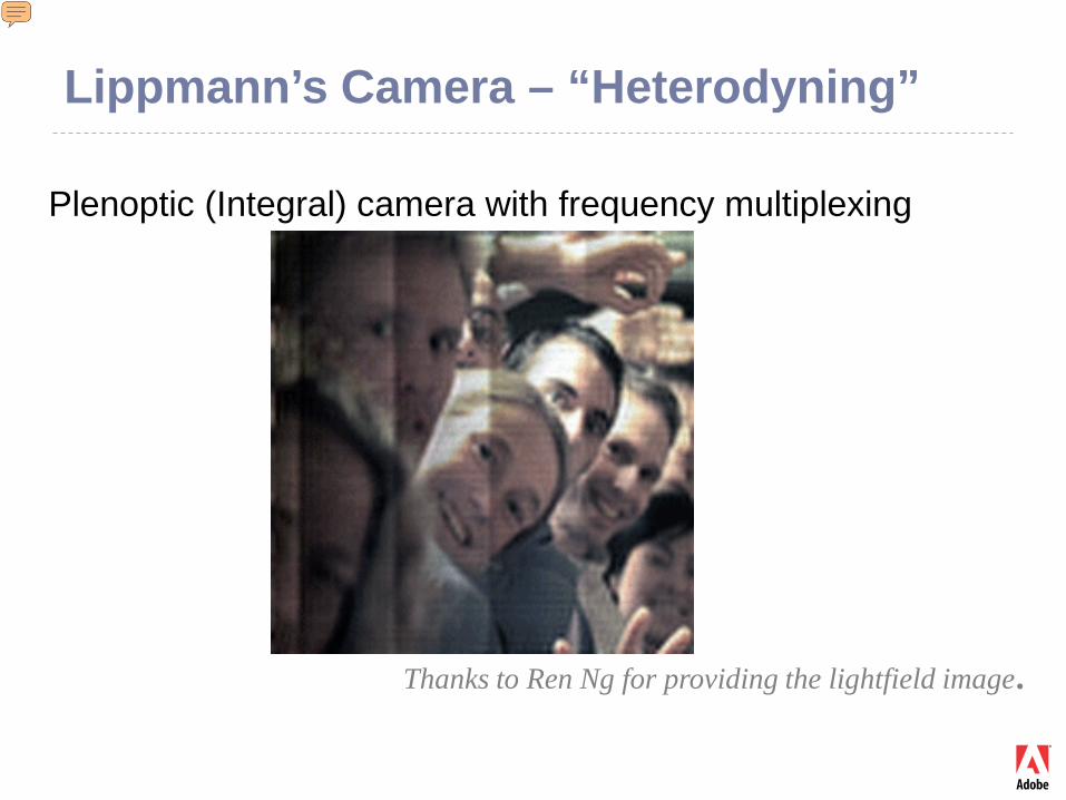
Thanks to Ren Ng for providing the lightfield image.
Plenoptic (Integral) camera with frequency multiplexing
Presenter
Presentation Notes
This is a demo that the method really works with Lippmann-type cameras. Also, it shows an artifact probably due to array manufacturing. This artifact is not visible with the space multiplexing approach. This experiment leads to the idea of recovering subtle camera information from the captured image, “lightfield forensics”.


![PLURICANONICAL SYSTEMS OF PROJECTIVE VARIETIES OF … · arXiv:math/0409318v3 [math.CV] 12 Oct 2004 PLURICANONICAL SYSTEMS OF PROJECTIVE VARIETIES OF GENERAL TYPE II Hajime TSUJI](https://static.fdocument.org/doc/165x107/600102dfc1a4617a690b6216/pluricanonical-systems-of-projective-varieties-of-arxivmath0409318v3-mathcv.jpg)

![Holonomy limits of complex projective structureshomepages.math.uic.edu/~ddumas/work/hol/hol.pdfplex projective structures (e.g. [Tan1] [Tan2] [SW] [D1]), for the purposes of TheoremsA{Dthe](https://static.fdocument.org/doc/165x107/5e32a36c6a6dfa6c71254474/holonomy-limits-of-complex-projective-ddumasworkholholpdf-plex-projective-structures.jpg)


![arXiv:1803.03253v1 [math.CV] 8 Mar 2018zeriahi/AAZ-ProjLogPot-arXiv201… · arXiv:1803.03253v1 [math.CV] 8 Mar 2018 PROJECTIVE LOGARITHMIC POTENTIALS S. ASSERDA, FATIMA Z. ASSILA](https://static.fdocument.org/doc/165x107/5fa2ad5ad514ee1cc34370f9/arxiv180303253v1-mathcv-8-mar-2018-zeriahiaaz-projlogpot-arxiv201-arxiv180303253v1.jpg)