QB50 CubeSat PDR Team: STAR - colorado.edu · magnetometer readings 61 cm 22. Helmholtz Cage...
89
QB50 CubeSat PDR Team: STAR Satellite Testbed for Attitude Response Matt Hong, Nick Andrews, Dylan Cooper, Colin Peterson, Nathan Eckert, Sasanka Bathula, Cole Glommen 1
Transcript of QB50 CubeSat PDR Team: STAR - colorado.edu · magnetometer readings 61 cm 22. Helmholtz Cage...
QB50 CubeSat PDRTeam: STAR
Satellite Testbed for Attitude Response
Matt Hong, Nick Andrews, Dylan Cooper, Colin Peterson, Nathan Eckert, Sasanka Bathula, Cole Glommen
1
Presentation Outline
Mission Introduction
Project Description
Feasibility –Interface
Board
Feasibility –Helmholtz Cage Test
Backup Slides
Feasibility –Sun Sensor
Table
Status Summary
2
Mission Introduction
Mission Introduction
Project Description
Feasibility –Interface
Board
Feasibility –Helmholtz Cage Test
Backup Slides
Feasibility –Sun Sensor
Table
Status Summary
3
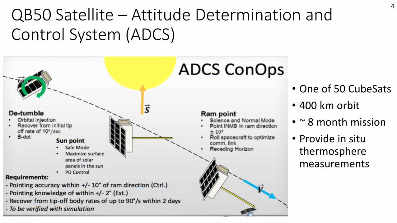
QB50 Satellite – Attitude Determination and Control System (ADCS)
• One of 50 CubeSats
• 400 km orbit
• ~ 8 month mission
• Provide in situ thermosphere measurements
4
Project Description
Mission Introduction
Project Description
Feasibility –Interface
Board
Feasibility –Helmholtz Cage Test
Backup Slides
Feasibility –Sun Sensor
Table
Status Summary
5

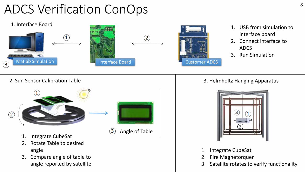
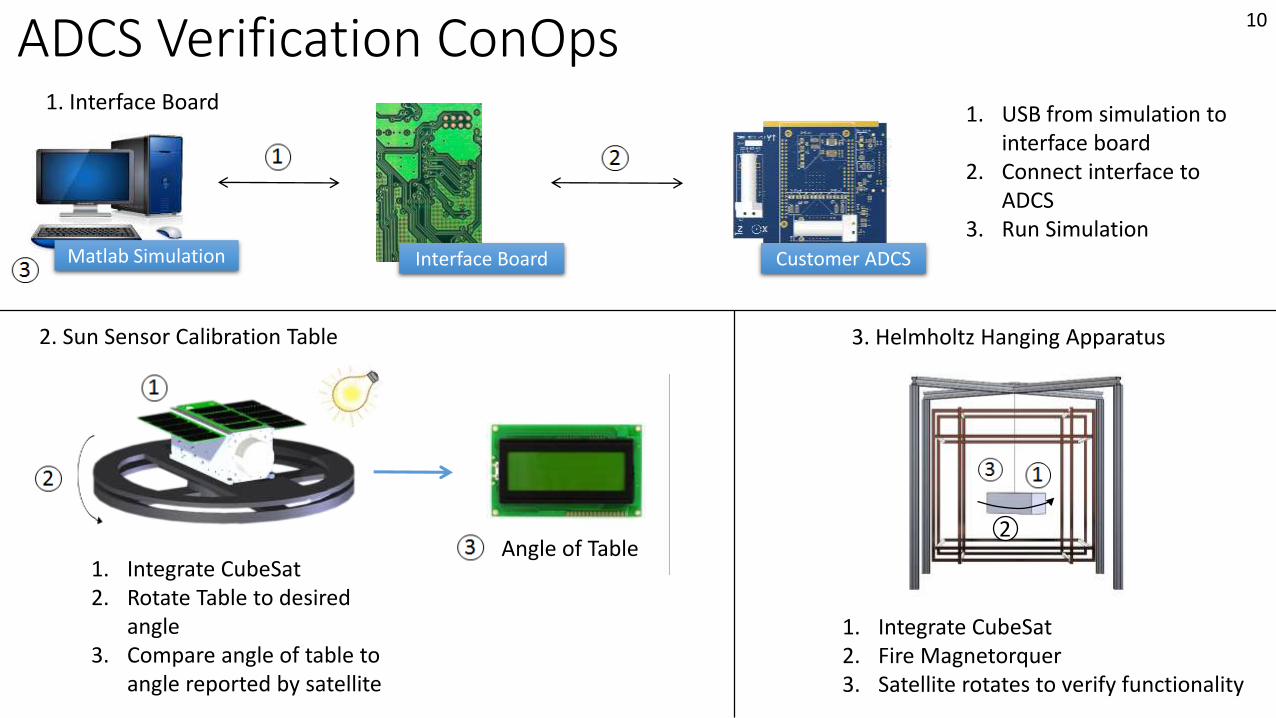
ADCS Verification ConOps1. Interface Board
1. USB from simulation to interface board
2. Connect interface to ADCS
3. Run SimulationInterface Board Customer ADCSMatlab Simulation
2. Sun Sensor Calibration Table
1. Integrate CubeSat2. Rotate Table to desired
angle3. Compare angle of table to
angle reported by satellite
Angle of Table
3. Helmholtz Hanging Apparatus
1. Integrate CubeSat2. Fire Magnetorquer3. Satellite rotates to verify functionality
2
6
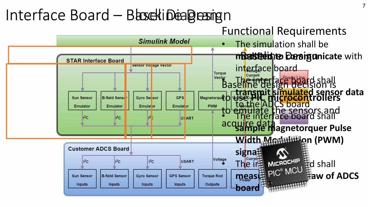
Interface Board – Block DiagramFunctional Requirements• The simulation shall be
modified to communicate with interface board
• The interface board shall transmit simulated sensor datato the ADCS board
• The interface board shall sample magnetorquer Pulse Width Modulation (PWM) signals
• The interface board shall measure power draw of ADCS board
Baseline design decision is to use PIC microcontrollers to emulate the sensors and acquire data
Baseline Design
Interface Board – Baseline Design7
ADCS Verification ConOps1. Interface Board
1. USB from simulation to interface board
2. Connect interface to ADCS
3. Run SimulationInterface Board Customer ADCSMatlab Simulation
2. Sun Sensor Calibration Table
1. Integrate CubeSat2. Rotate Table to desired
angle3. Compare angle of table to
angle reported by satellite
Angle of Table
3. Helmholtz Hanging Apparatus
1. Integrate CubeSat2. Fire Magnetorquer3. Satellite rotates to verify functionality
2
8
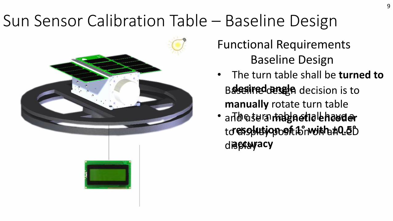
Sun Sensor Calibration Table – Baseline DesignFunctional Requirements
• The turn table shall be turned to desired angle
• The turn table shall have a resolution of 1° with ±0.5°accuracy
Baseline Design
Baseline design decision is to manually rotate turn table and use a magnetic encoder to display position on an LCD display
9
ADCS Verification ConOps1. Interface Board
1. USB from simulation to interface board
2. Connect interface to ADCS
3. Run SimulationInterface Board Customer ADCSMatlab Simulation
2. Sun Sensor Calibration Table
1. Integrate CubeSat2. Rotate Table to desired
angle3. Compare angle of table to
angle reported by satellite
Angle of Table
3. Helmholtz Hanging Apparatus
1. Integrate CubeSat2. Fire Magnetorquer3. Satellite rotates to verify functionality
2
10
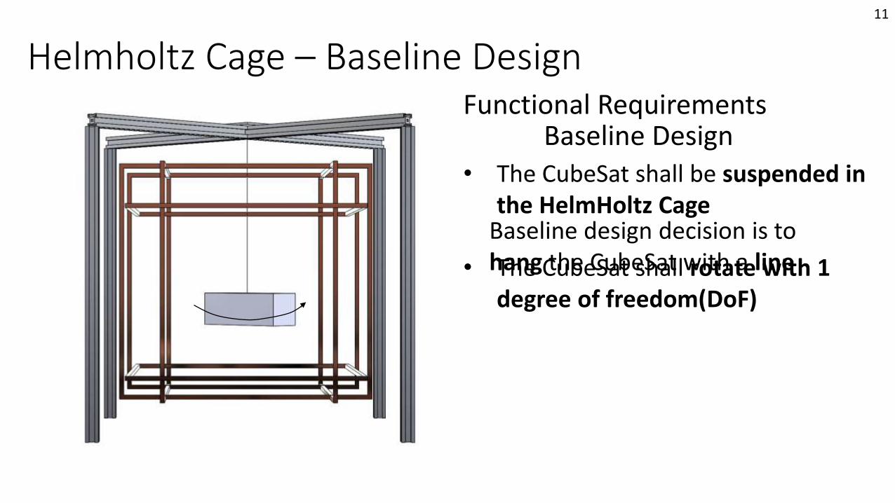
Helmholtz Cage – Baseline DesignFunctional Requirements
• The CubeSat shall be suspended in the HelmHoltz Cage
• The CubeSat shall rotate with 1 degree of freedom(DoF)
Baseline Design
Baseline design decision is to hang the CubeSat with a line
11
Baseline FeasibilityInterface Board
Mission Introduction
Project Description
Feasibility –Interface
Board
Feasibility –Helmholtz Cage Test
Backup Slides
Feasibility –Sun Sensor
Table
Status Summary
12
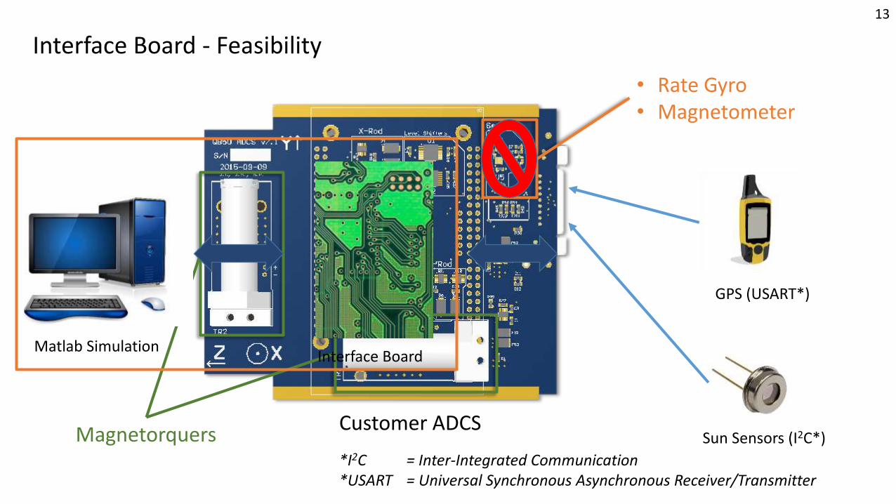
Customer ADCS
Interface Board - Feasibility
• Rate Gyro• Magnetometer
GPS (USART*)
Sun Sensors (I2C*)Magnetorquers
Matlab SimulationInterface Board
*I2C = Inter-Integrated Communication*USART = Universal Synchronous Asynchronous Receiver/Transmitter
13
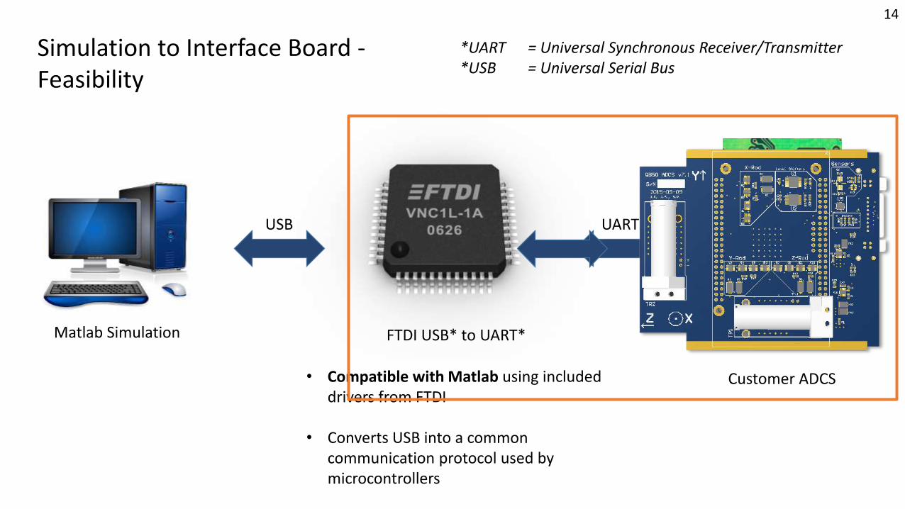
• Compatible with Matlab using included drivers from FTDI
• Converts USB into a common communication protocol used by microcontrollers
Simulation to Interface Board -Feasibility
Interface BoardMatlab Simulation FTDI USB* to UART*
USB UART
Customer ADCS
*UART = Universal Synchronous Receiver/Transmitter*USB = Universal Serial Bus
14
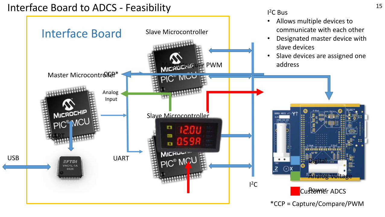
Master Microcontroller
Slave Microcontroller
Slave Microcontroller
Interface Board
I2C Bus• Allows multiple devices to
communicate with each other• Designated master device with
slave devices• Slave devices are assigned one
address
Customer ADCS
UART
UART
USB
Interface Board to ADCS - Feasibility
I2C
15
Magnetorquer PWM
Analog Input
CCP*
Digital
Analog Voltage
*CCP = Capture/Compare/PWM
Power
Baseline FeasibilitySun Sensor Calibration Table
Mission Introduction
Project Description
Feasibility –Interface
Board
Feasibility –Helmholtz Cage Test
Backup Slides
Feasibility –Sun Sensor
Table
Status Summary
16
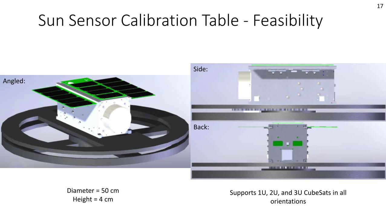
Sun Sensor Calibration Table - Feasibility
Angled:
Side:
Back:
Diameter = 50 cmHeight = 4 cm
Supports 1U, 2U, and 3U CubeSats in all orientations
17
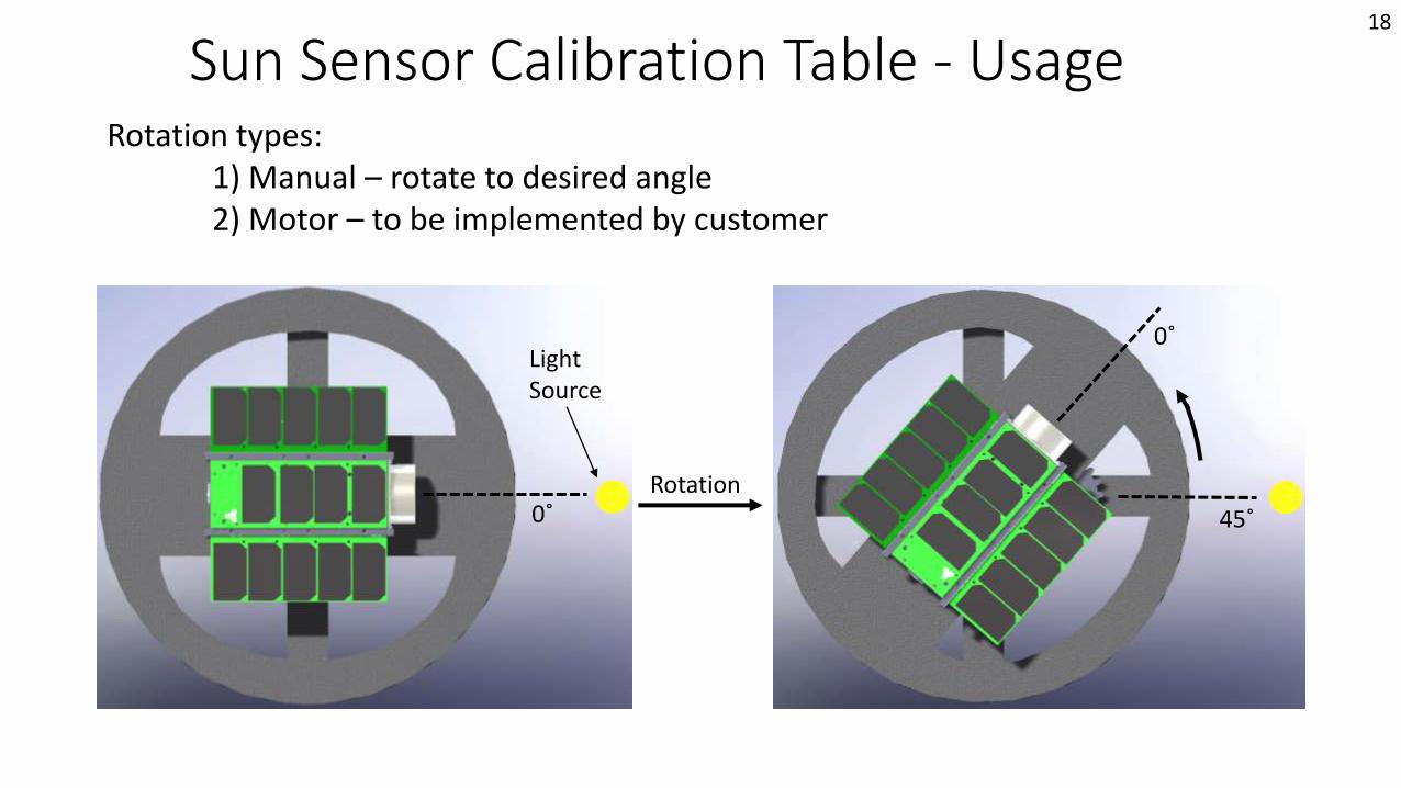
Sun Sensor Calibration Table - Usage
Light Source
Rotation
Rotation types:1) Manual – rotate to desired angle2) Motor – to be implemented by customer
0˚
0˚
45˚
18
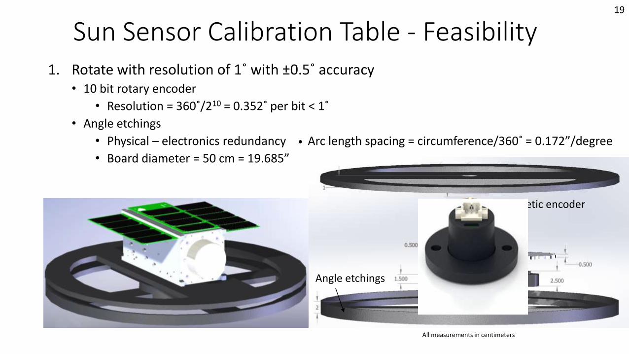
Sun Sensor Calibration Table - Feasibility1. Rotate with resolution of 1˚ with ±0.5˚ accuracy
• 10 bit rotary encoder
• Resolution = 360˚/210 = 0.352˚ per bit < 1˚
• Angle etchings
• Physical – electronics redundancy • Arc length spacing = circumference/360˚ = 0.172”/degree
• Board diameter = 50 cm = 19.685”
Magnetic encoder
Angle etchings
All measurements in centimeters
19
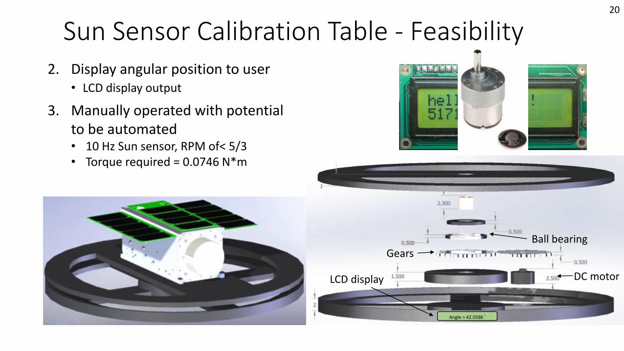
Sun Sensor Calibration Table - Feasibility2. Display angular position to user
• LCD display output
Angle = 42.0586 ˚
LCD display
3. Manually operated with potential to be automated• 10 Hz Sun sensor, RPM of< 5/3• Torque required = 0.0746 N*m
Ball bearing
DC motor
Gears
20
Baseline FeasibilityHelmholtz Cage Test
Mission Introduction
Project Description
Feasibility –Interface
Board
Feasibility –Helmholtz Cage Test
Backup Slides
Feasibility –Sun Sensor
Table
Status Summary
21
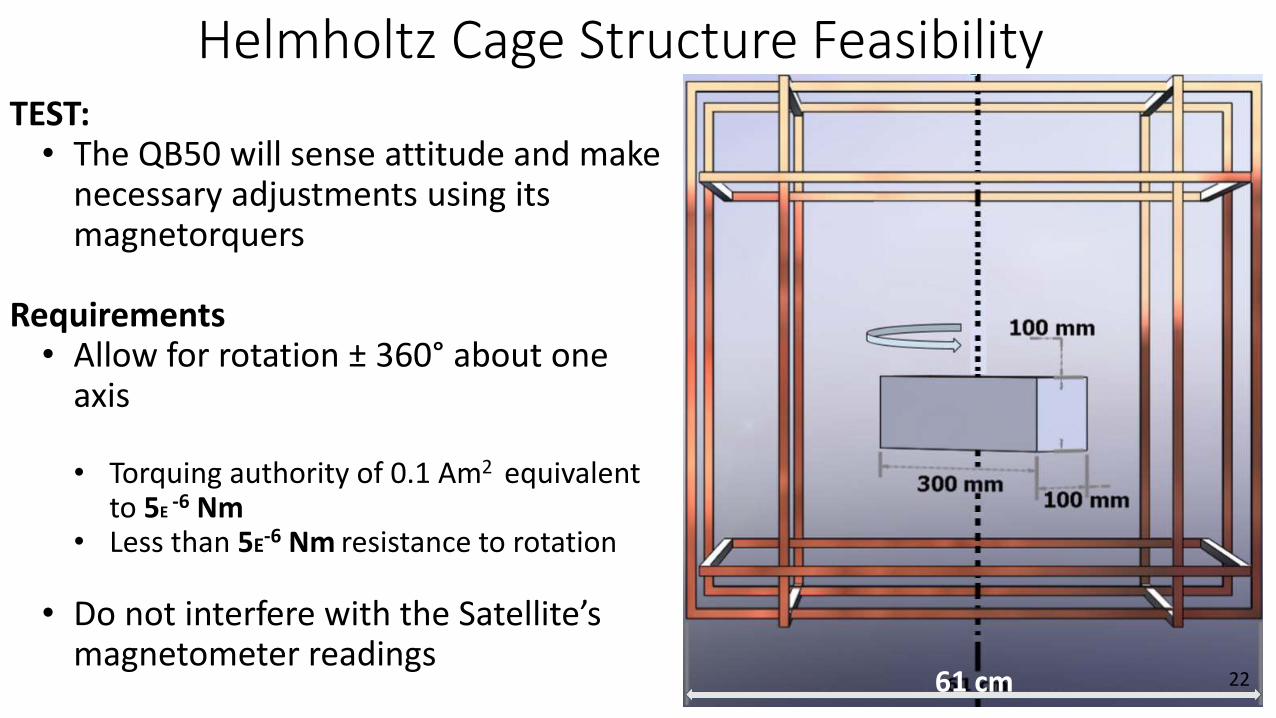
Helmholtz Cage Structure FeasibilityTEST:• The QB50 will sense attitude and make
necessary adjustments using its magnetorquers
Requirements• Allow for rotation ± 360° about one
axis
• Torquing authority of 0.1 Am2 equivalent to 5E
-6 Nm• Less than 5E-6 Nm resistance to rotation
• Do not interfere with the Satellite’s magnetometer readings
61 cm 22
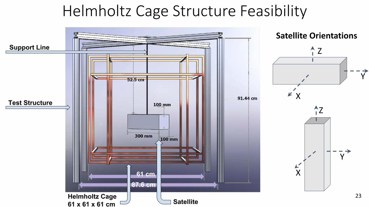
Helmholtz Cage Structure Feasibility
Satellite Orientations
X
Y
Z
Y
X
Z
23
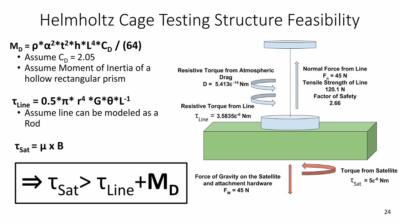
Helmholtz Cage Testing Structure Feasibility
MD = ρ*α2*t2*h*L4*CD / (64)• Assume CD = 2.05• Assume Moment of Inertia of a
hollow rectangular prism
τLine = 0.5*π* r4 *G*θ*L-1
• Assume line can be modeled as a Rod
τSat = μ x B
⇒ τSat> τLine+MD24
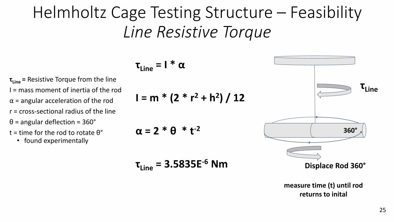
Helmholtz Cage Testing Structure – Feasibility Line Resistive Torque
τLine = Resistive Torque from the line
I = mass moment of inertia of the rod
α = angular acceleration of the rod
r = cross-sectional radius of the line
θ = angular deflection = 360°
t = time for the rod to rotate θ°• found experimentally
τLine = I * α
I = m * (2 * r2 + h2) / 12
α = 2 * θ * t-2
τLine = 3.5835E-6 Nm Displace Rod 360°
τLine
measure time (t) until rod returns to inital
360°
25
Status Summary
Mission Introduction
Project Description
Feasibility –Interface
Board
Feasibility –Helmholtz Cage Test
Backup Slides
Feasibility –Sun Sensor
Table
Status Summary
26
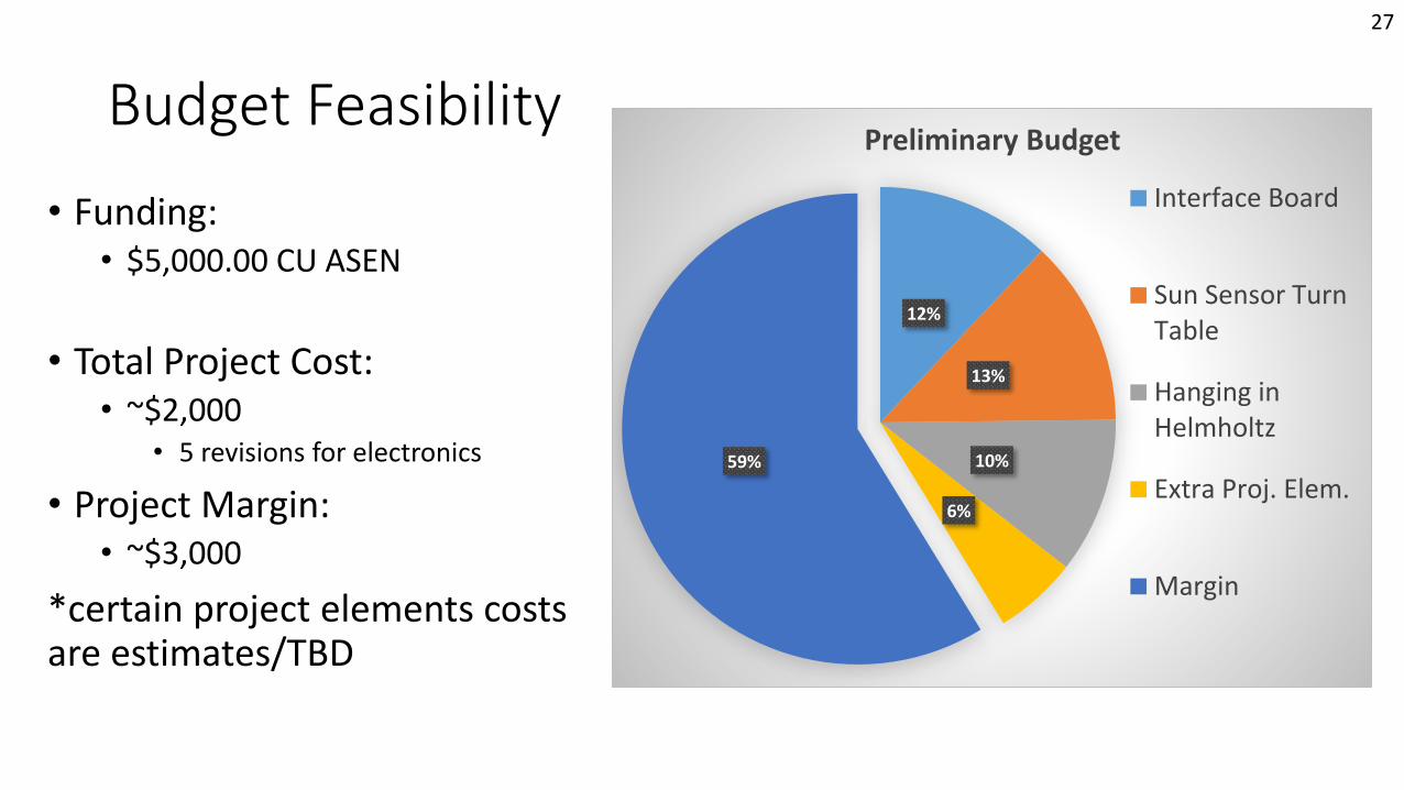
Budget Feasibility
• Funding:• $5,000.00 CU ASEN
• Total Project Cost:• ~$2,000
• 5 revisions for electronics
• Project Margin:• ~$3,000
*certain project elements costs are estimates/TBD
12%
13%
10%
6%
59%
Preliminary Budget
Interface Board
Sun Sensor TurnTable
Hanging inHelmholtz
Extra Proj. Elem.
Margin
27
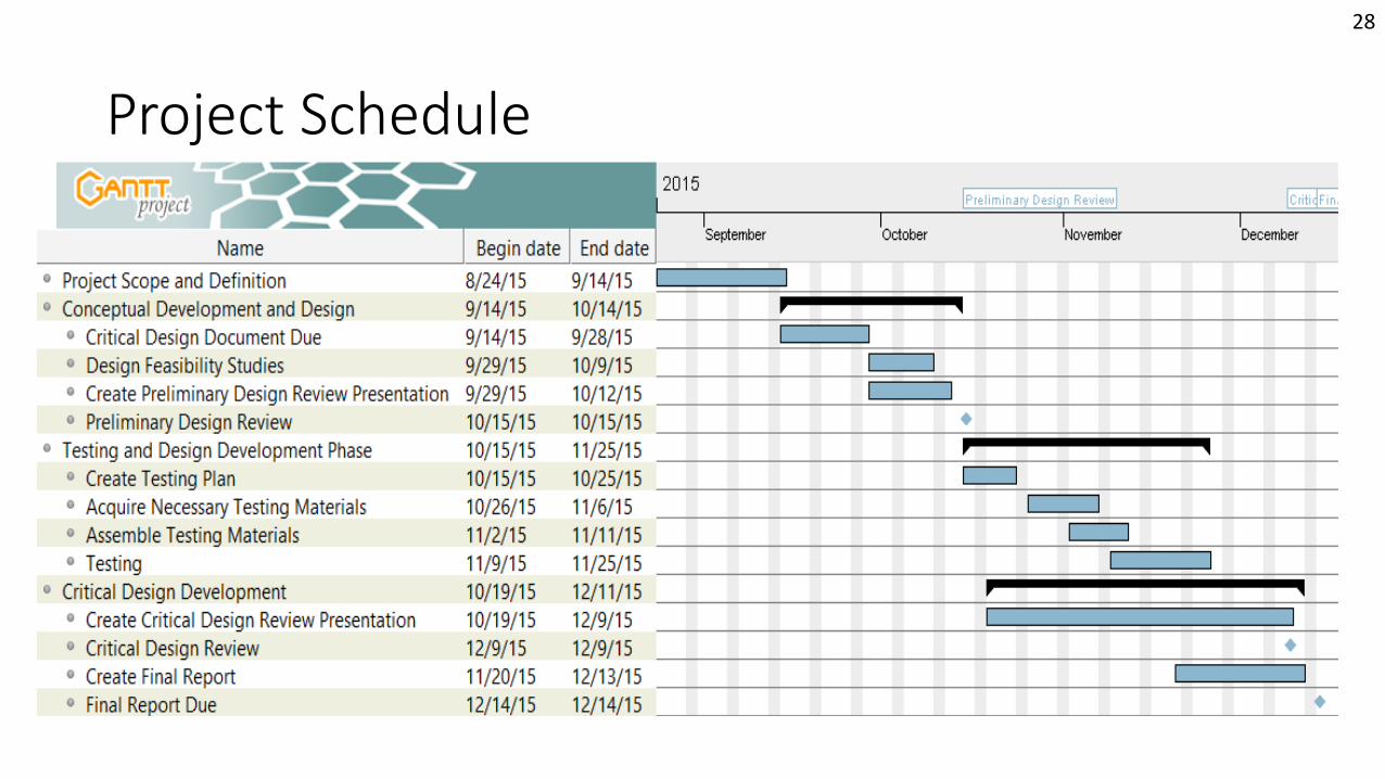
Project Schedule
28
Future Studies
• Interface Board• Design layout of interface board• Selection of precise PIC microcontrollers
• Sun Sensor Calibration Table• Design encoder-LCD circuit • Selection of gears and gear ratio
• Helmholtz Cage Test• Further testing of hanging lines for margin
• Software• Increase of simulation accuracy
29
Questions?
Mission Introduction
Project Description
Feasibility –Interface
Board
Feasibility –Helmholtz Cage Test
Backup Slides
Feasibility –Sun Sensor
Table
Status Summary
30
Backup Slides• Interface Board
• Simulation
• Sun Sensor Calibration Table
• Helmholtz Cage Test
• Logistics
Mission Introduction
Project Description
Feasibility –Interface
Board
Feasibility –Helmholtz Cage Test
Backup Slides
Feasibility –Sun Sensor
Table
Status Summary
31
Backup Slides
Interface Board
Mission Introduction
Project Description
Feasibility –Interface
Board
Feasibility –Helmholtz Cage Test
Backup Slides
Feasibility –Sun Sensor
Table
Status Summary
32
Backup Slides
Interface Board: Requirements
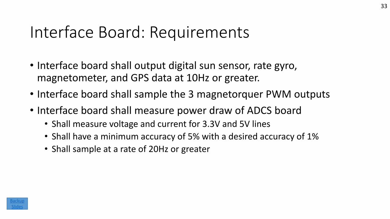
• Interface board shall output digital sun sensor, rate gyro, magnetometer, and GPS data at 10Hz or greater.
• Interface board shall sample the 3 magnetorquer PWM outputs
• Interface board shall measure power draw of ADCS board• Shall measure voltage and current for 3.3V and 5V lines
• Shall have a minimum accuracy of 5% with a desired accuracy of 1%
• Shall sample at a rate of 20Hz or greater
33
Backup Slides
Functional Requirement 1
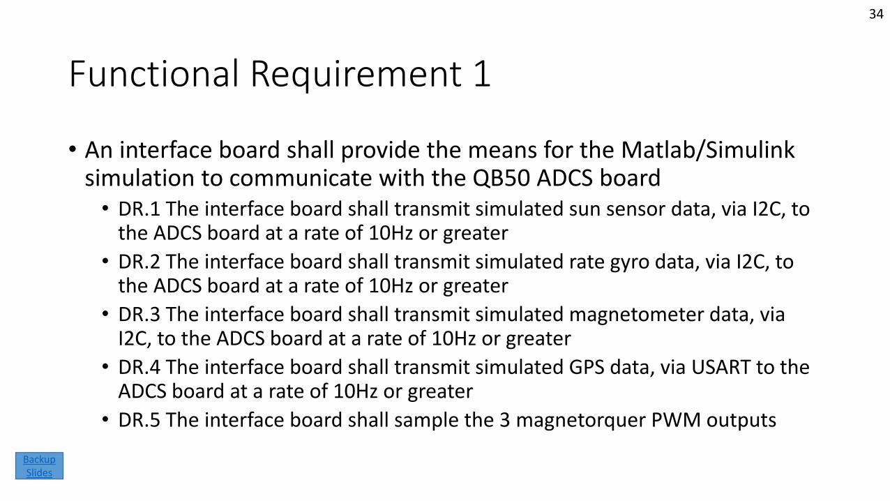
• An interface board shall provide the means for the Matlab/Simulink simulation to communicate with the QB50 ADCS board• DR.1 The interface board shall transmit simulated sun sensor data, via I2C, to
the ADCS board at a rate of 10Hz or greater
• DR.2 The interface board shall transmit simulated rate gyro data, via I2C, to the ADCS board at a rate of 10Hz or greater
• DR.3 The interface board shall transmit simulated magnetometer data, via I2C, to the ADCS board at a rate of 10Hz or greater
• DR.4 The interface board shall transmit simulated GPS data, via USART to the ADCS board at a rate of 10Hz or greater
• DR.5 The interface board shall sample the 3 magnetorquer PWM outputs
34
Backup Slides
Cont.
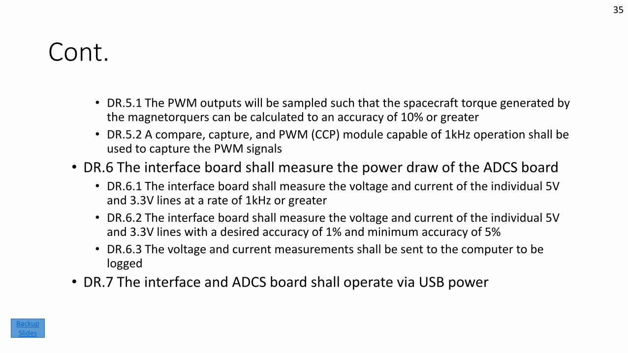
• DR.5.1 The PWM outputs will be sampled such that the spacecraft torque generated by the magnetorquers can be calculated to an accuracy of 10% or greater
• DR.5.2 A compare, capture, and PWM (CCP) module capable of 1kHz operation shall be used to capture the PWM signals
• DR.6 The interface board shall measure the power draw of the ADCS board• DR.6.1 The interface board shall measure the voltage and current of the individual 5V
and 3.3V lines at a rate of 1kHz or greater
• DR.6.2 The interface board shall measure the voltage and current of the individual 5V and 3.3V lines with a desired accuracy of 1% and minimum accuracy of 5%
• DR.6.3 The voltage and current measurements shall be sent to the computer to be logged
• DR.7 The interface and ADCS board shall operate via USB power
35
Backup Slides
Functional Requirement 2
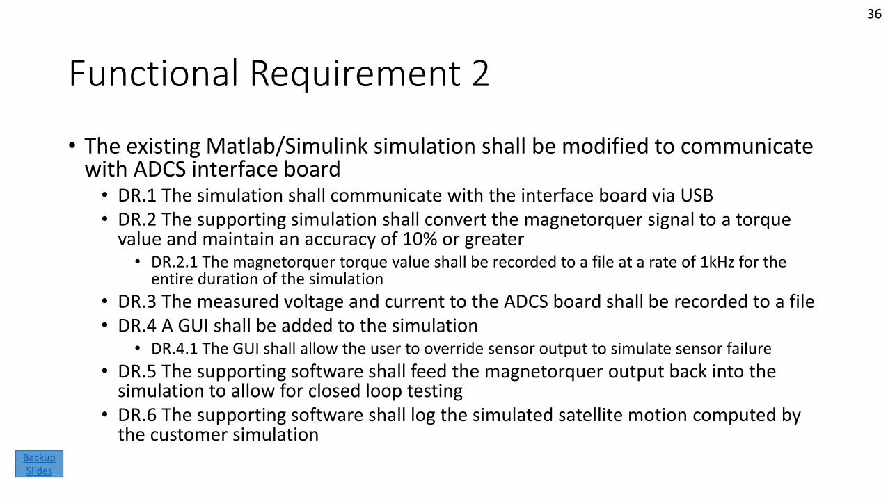
• The existing Matlab/Simulink simulation shall be modified to communicate with ADCS interface board• DR.1 The simulation shall communicate with the interface board via USB• DR.2 The supporting simulation shall convert the magnetorquer signal to a torque
value and maintain an accuracy of 10% or greater• DR.2.1 The magnetorquer torque value shall be recorded to a file at a rate of 1kHz for the
entire duration of the simulation
• DR.3 The measured voltage and current to the ADCS board shall be recorded to a file• DR.4 A GUI shall be added to the simulation
• DR.4.1 The GUI shall allow the user to override sensor output to simulate sensor failure
• DR.5 The supporting software shall feed the magnetorquer output back into the simulation to allow for closed loop testing
• DR.6 The supporting software shall log the simulated satellite motion computed by the customer simulation
36
Backup Slides
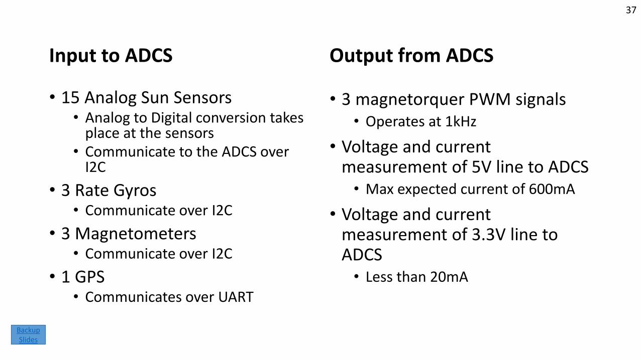
Input to ADCS
• 15 Analog Sun Sensors• Analog to Digital conversion takes
place at the sensors• Communicate to the ADCS over
I2C
• 3 Rate Gyros• Communicate over I2C
• 3 Magnetometers • Communicate over I2C
• 1 GPS• Communicates over UART
Output from ADCS
• 3 magnetorquer PWM signals• Operates at 1kHz
• Voltage and current measurement of 5V line to ADCS• Max expected current of 600mA
• Voltage and current measurement of 3.3V line to ADCS• Less than 20mA
37
Backup Slides
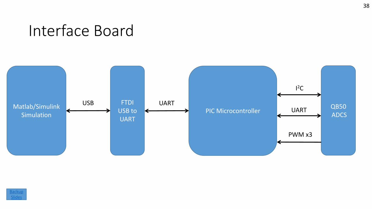
Interface Board
Matlab/Simulink Simulation
QB50ADCS
FTDIUSB to UART
PIC MicrocontrollerUSB UART
UART
I2C
PWM x3
38
Backup Slides
39
Backup Slides
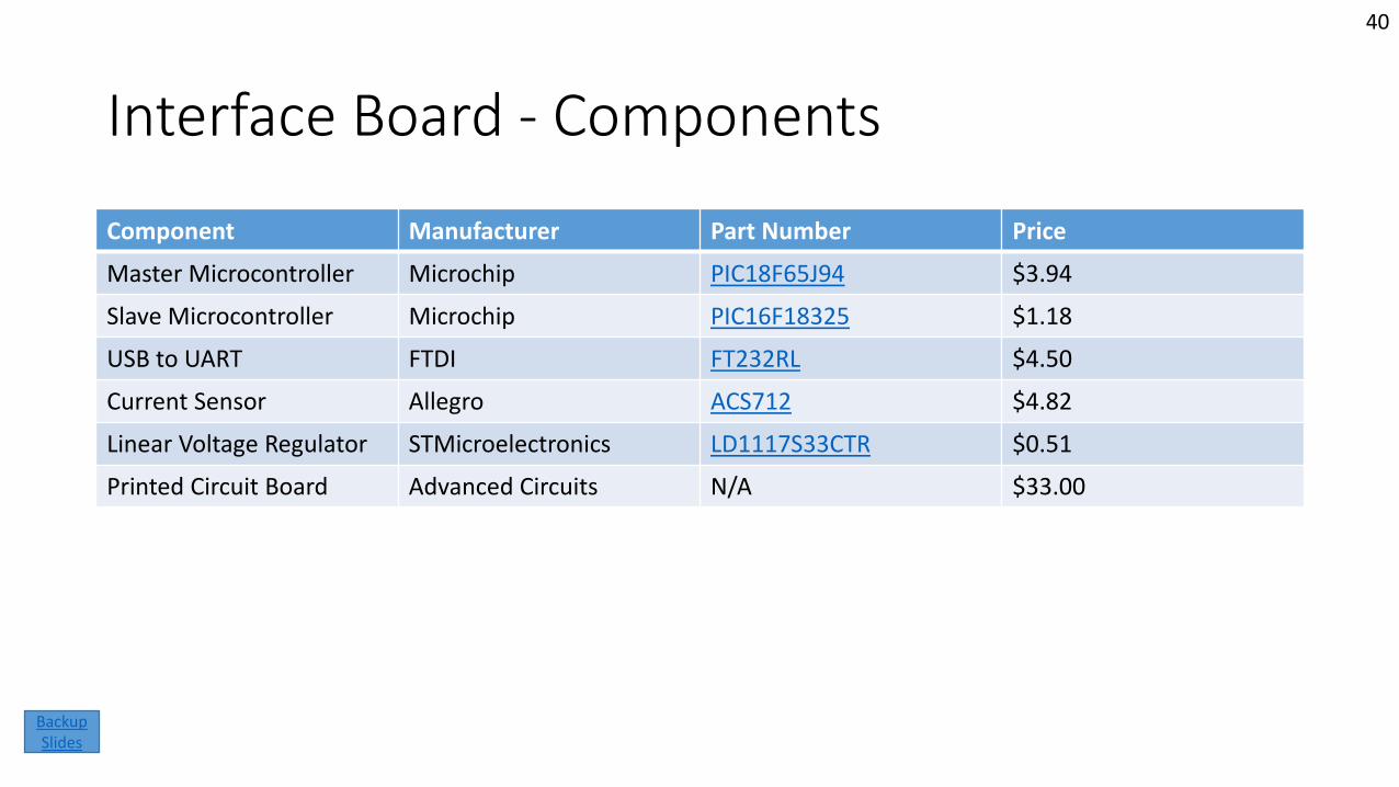
Interface Board - Components
Component Manufacturer Part Number Price
Master Microcontroller Microchip PIC18F65J94 $3.94
Slave Microcontroller Microchip PIC16F18325 $1.18
USB to UART FTDI FT232RL $4.50
Current Sensor Allegro ACS712 $4.82
Linear Voltage Regulator STMicroelectronics LD1117S33CTR $0.51
Printed Circuit Board Advanced Circuits N/A $33.00
40
Backup Slides
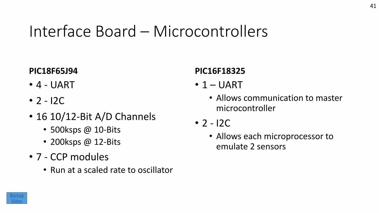
Interface Board – Microcontrollers
PIC18F65J94
• 4 - UART
• 2 - I2C
• 16 10/12-Bit A/D Channels• 500ksps @ 10-Bits
• 200ksps @ 12-Bits
• 7 - CCP modules• Run at a scaled rate to oscillator
PIC16F18325
• 1 – UART• Allows communication to master
microcontroller
• 2 - I2C• Allows each microprocessor to
emulate 2 sensors
41
Backup Slides
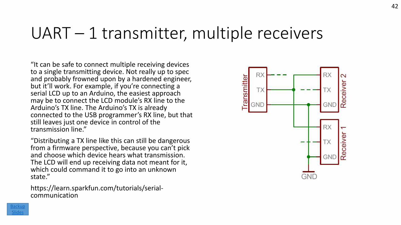
UART – 1 transmitter, multiple receivers
“It can be safe to connect multiple receiving devices to a single transmitting device. Not really up to spec and probably frowned upon by a hardened engineer, but it’ll work. For example, if you’re connecting a serial LCD up to an Arduino, the easiest approach may be to connect the LCD module’s RX line to the Arduino’s TX line. The Arduino’s TX is already connected to the USB programmer’s RX line, but that still leaves just one device in control of the transmission line.”
“Distributing a TX line like this can still be dangerous from a firmware perspective, because you can’t pick and choose which device hears what transmission. The LCD will end up receiving data not meant for it, which could command it to go into an unknown state.”
https://learn.sparkfun.com/tutorials/serial-communication
42
Backup Slides
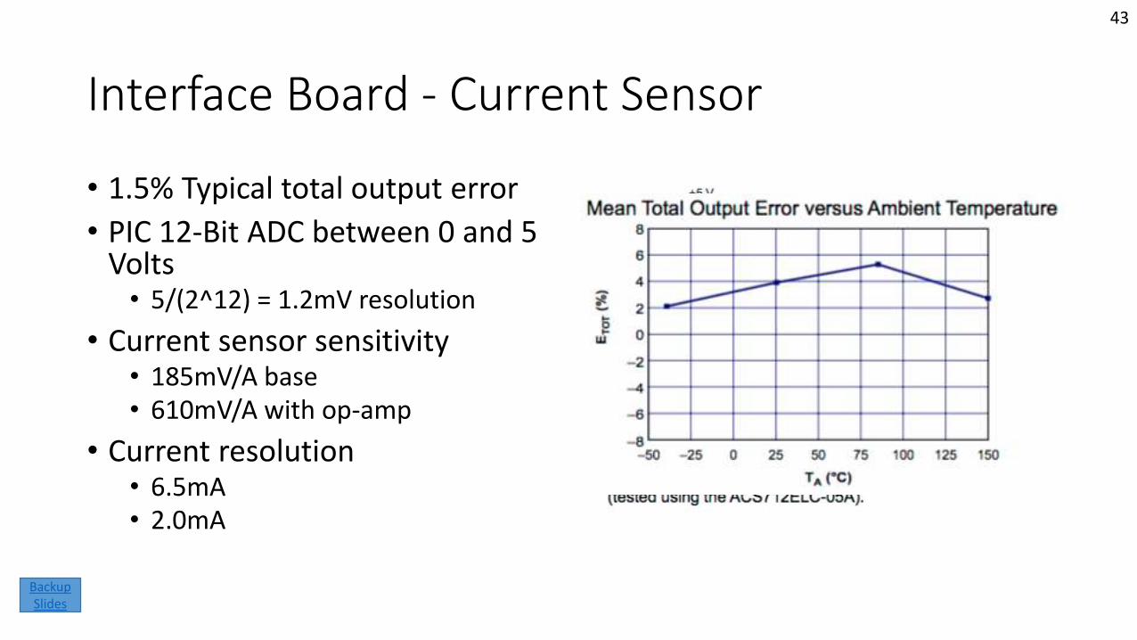
Interface Board - Current Sensor
• 1.5% Typical total output error
• PIC 12-Bit ADC between 0 and 5 Volts• 5/(2^12) = 1.2mV resolution
• Current sensor sensitivity• 185mV/A base• 610mV/A with op-amp
• Current resolution• 6.5mA• 2.0mA
43
Backup Slides
Interface Board – Power Budget
Interface Board
• Microchip eXtreme Low Power• As low as 35uA/Mhz for 8-Bit MCU
• 0.35mA at 10Mhz
• <10mA for 23 MCUs
• FTDI < 25mA
• Current Sensor < 13mA
Total: ~48mA
Customer ADCS
• Beaglebone < 500mA• Observed ~250mA in normal
operation
• Magnetorquers• 90 Ohms @ 5V is 56mA max
• <167mA for 3 magnetorquers
• Sensors < 20mA
Total: ~ 437mA
44
Backup Slides
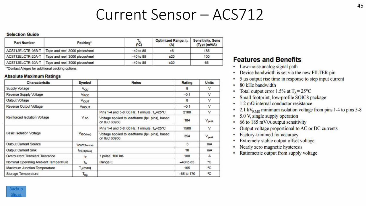
Current Sensor – ACS71245
Backup Slides
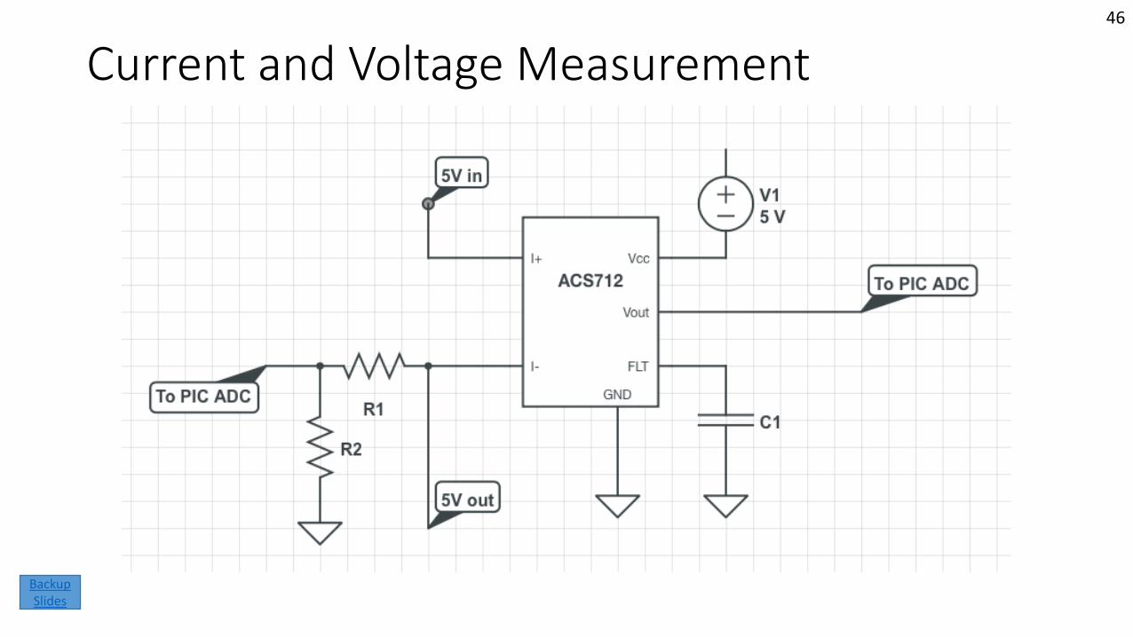
Current and Voltage Measurement46
Backup Slides
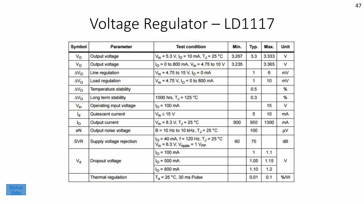
Voltage Regulator – LD1117
47
Backup Slides
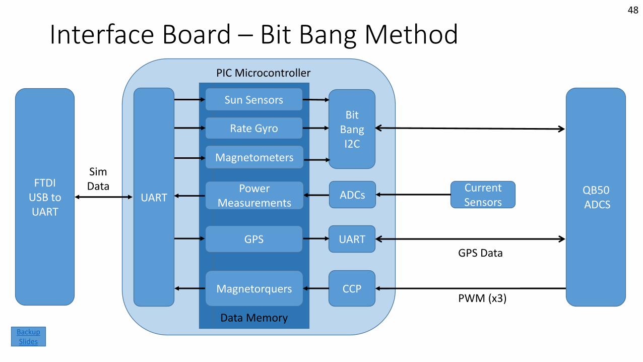
Interface Board – Bit Bang Method
QB50ADCS
Rate Gyro
Magnetometers
GPS
Sun SensorsBit
Bang I2C
UART
Magnetorquers CCP
PIC Microcontroller
UARTFTDI
USB to UART
SimData
PWM (x3)
GPS Data
Power Measurements
Data Memory
ADCsCurrent Sensors
48
Backup Slides
Simulation
Mission Introduction
Project Description
Feasibility –Interface
Board
Feasibility –Helmholtz Cage Test
Backup Slides
Feasibility –Sun Sensor
Table
Status Summary
49
Backup Slides
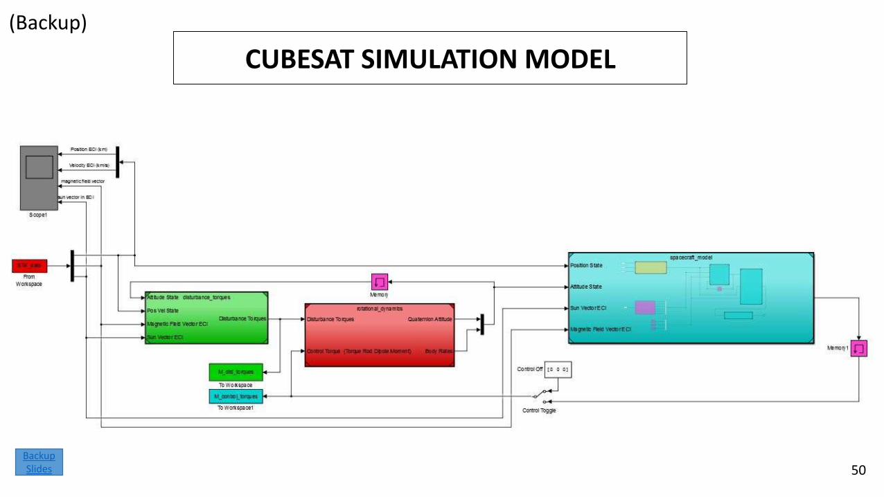
CUBESAT SIMULATION MODEL
(Backup)
50Backup Slides
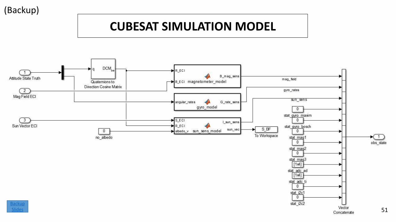
CUBESAT SIMULATION MODEL
(Backup)
51Backup Slides
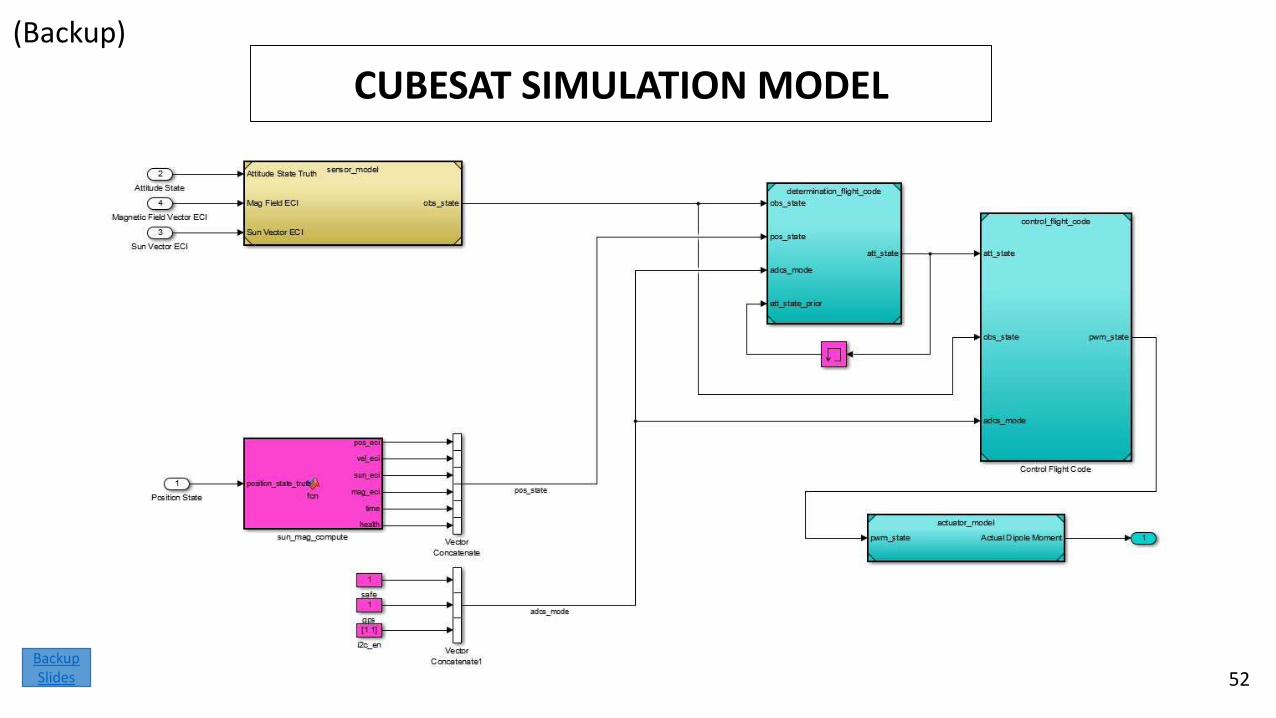
CUBESAT SIMULATION MODEL
(Backup)
52Backup Slides
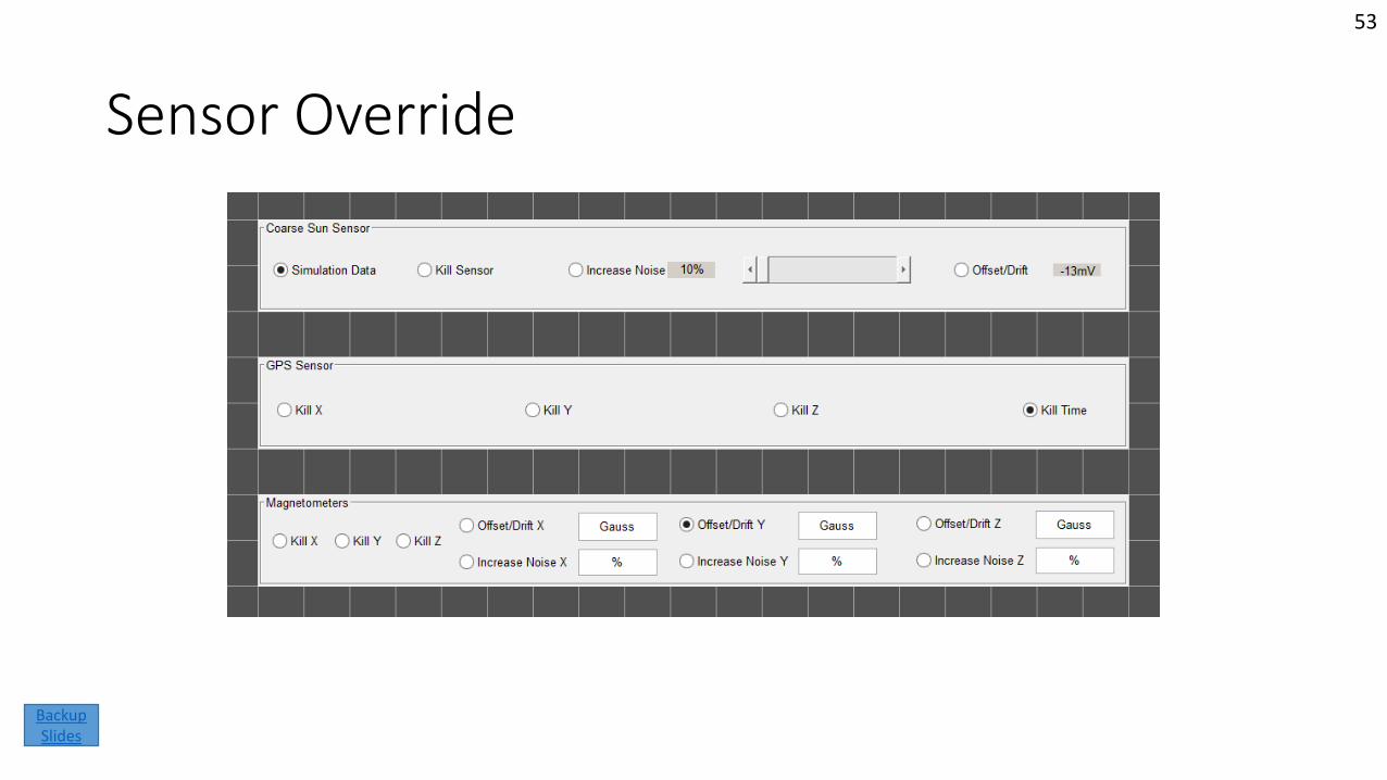
Sensor Override
53
Backup Slides
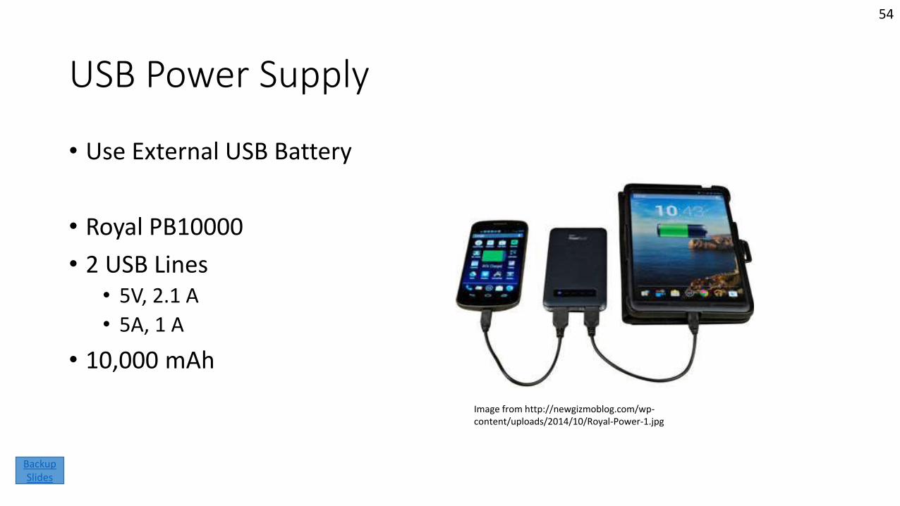
USB Power Supply
• Use External USB Battery
• Royal PB10000
• 2 USB Lines• 5V, 2.1 A
• 5A, 1 A
• 10,000 mAh
Image from http://newgizmoblog.com/wp-content/uploads/2014/10/Royal-Power-1.jpg
54
Backup Slides
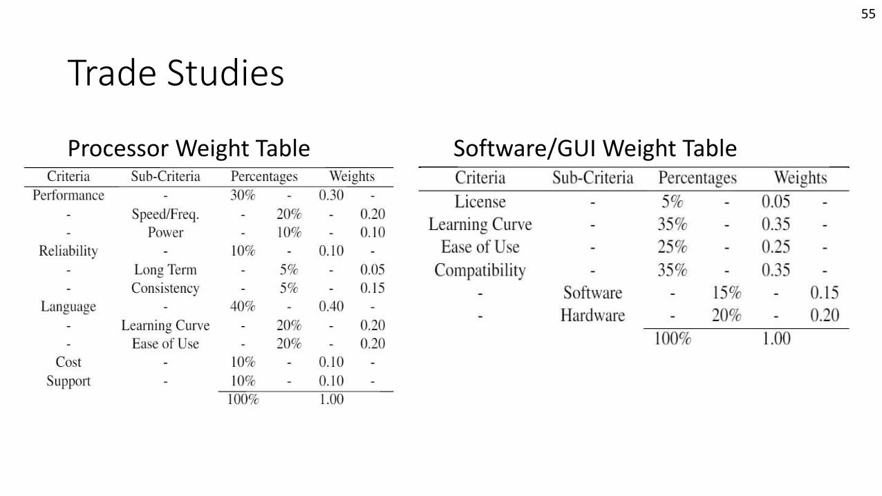
Trade Studies
Processor Weight Table Software/GUI Weight Table
55
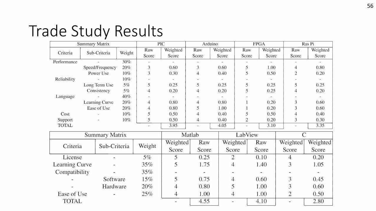
Trade Study Results
56
Sun Sensor Calibration Table
Mission Introduction
Project Description
Feasibility –Interface
Board
Feasibility –Helmholtz Cage Test
Backup Slides
Feasibility –Sun Sensor
Table
Status Summary
57
Backup Slides
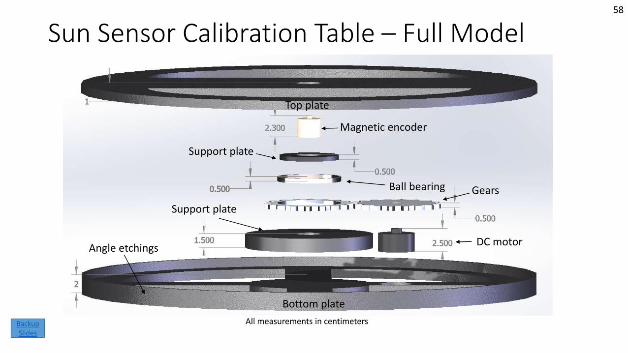
Sun Sensor Calibration Table – Full Model
All measurements in centimeters
Top plate
Bottom plate
Angle etchings
Support plate
Gears
DC motor
Ball bearing
Support plate
Magnetic encoder
58
Backup Slides
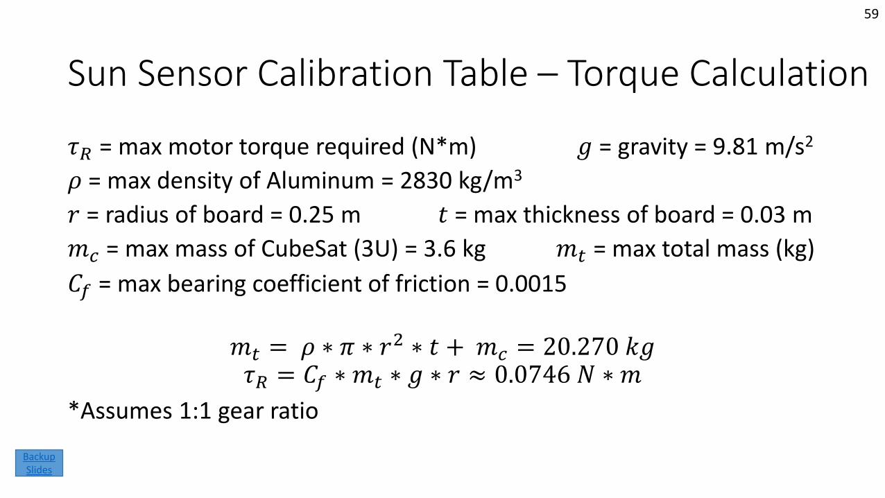
Sun Sensor Calibration Table – Torque Calculation
𝜏𝑅 = max motor torque required (N*m) 𝑔 = gravity = 9.81 m/s2
𝜌 = max density of Aluminum = 2830 kg/m3
𝑟 = radius of board = 0.25 m 𝑡 = max thickness of board = 0.03 m
𝑚𝑐 = max mass of CubeSat (3U) = 3.6 kg 𝑚𝑡 = max total mass (kg)
𝐶𝑓 = max bearing coefficient of friction = 0.0015
𝑚𝑡 = 𝜌 ∗ 𝜋 ∗ 𝑟2 ∗ 𝑡 + 𝑚𝑐 = 20.270 𝑘𝑔𝜏𝑅 = 𝐶𝑓 ∗ 𝑚𝑡 ∗ 𝑔 ∗ 𝑟 ≈ 0.0746 𝑁 ∗ 𝑚
*Assumes 1:1 gear ratio
59
Backup Slides
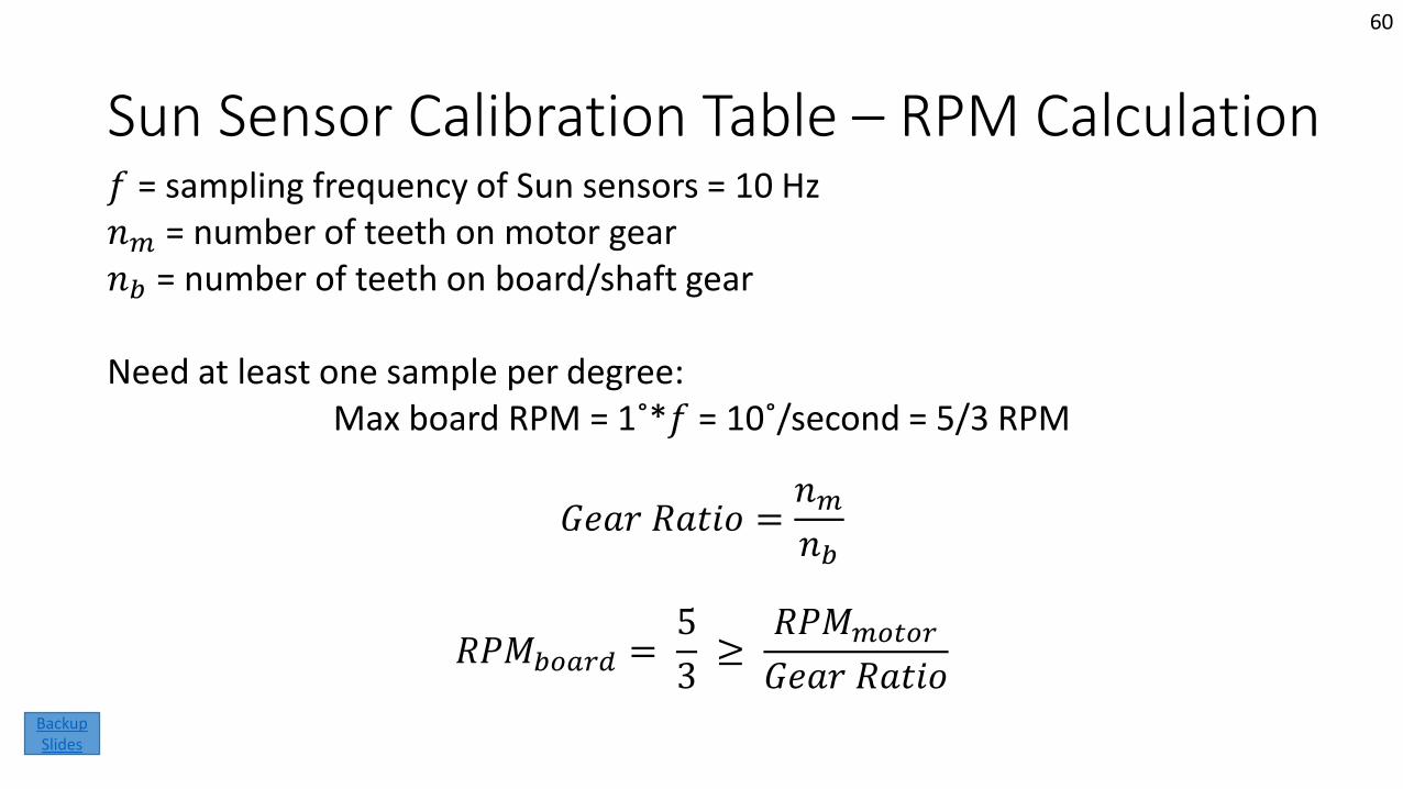
Sun Sensor Calibration Table – RPM Calculation𝑓 = sampling frequency of Sun sensors = 10 Hz𝑛𝑚 = number of teeth on motor gear𝑛𝑏 = number of teeth on board/shaft gear
Need at least one sample per degree:Max board RPM = 1˚*𝑓 = 10˚/second = 5/3 RPM
𝐺𝑒𝑎𝑟 𝑅𝑎𝑡𝑖𝑜 =𝑛𝑚𝑛𝑏
𝑅𝑃𝑀𝑏𝑜𝑎𝑟𝑑 =5
3≥
𝑅𝑃𝑀𝑚𝑜𝑡𝑜𝑟
𝐺𝑒𝑎𝑟 𝑅𝑎𝑡𝑖𝑜
60
Backup Slides
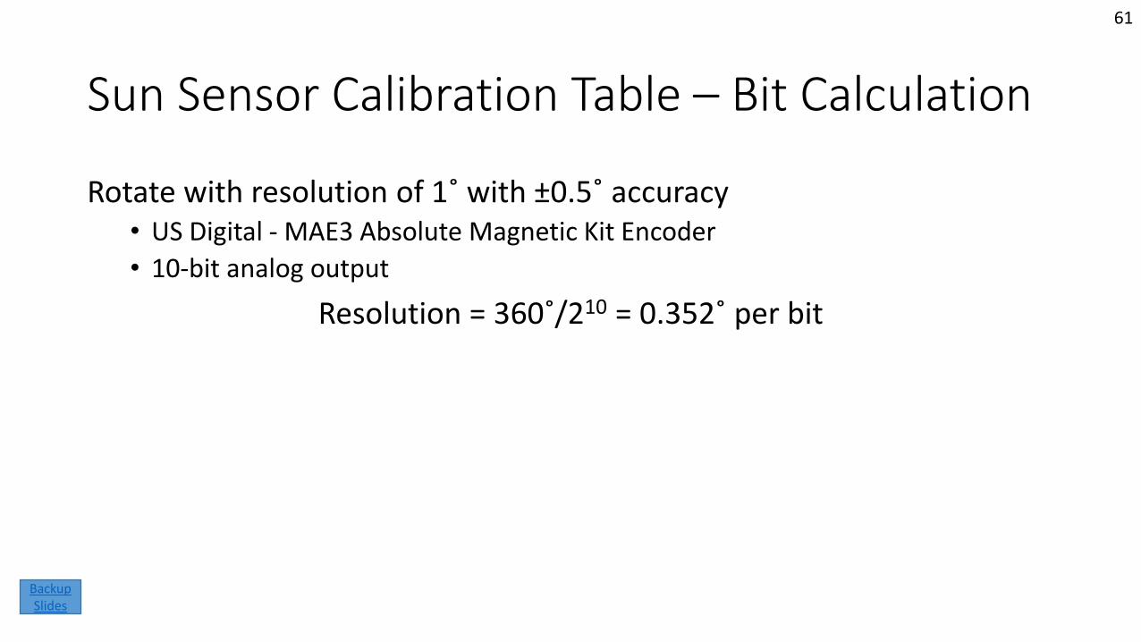
Sun Sensor Calibration Table – Bit Calculation
Rotate with resolution of 1˚ with ±0.5˚ accuracy• US Digital - MAE3 Absolute Magnetic Kit Encoder
• 10-bit analog output
Resolution = 360˚/210 = 0.352˚ per bit
61
Backup Slides
Sun Sensor Calibration Table – Reflectivity
Reflectivity less than or equal to 5% for visible wavelengths (400-700 nm) • Avian Technologies LLC
• Avian Black-S coating has reflectance of 3.1% in visible wavelengths
62
Backup Slides
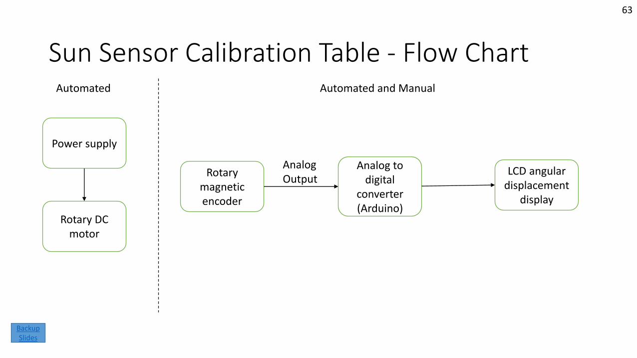
Sun Sensor Calibration Table - Flow Chart
Rotary magnetic encoder
Analog to digital
converter (Arduino)
Analog Output
LCD angular displacement
display
Power supply
Rotary DC motor
Automated and ManualAutomated
63
Backup Slides
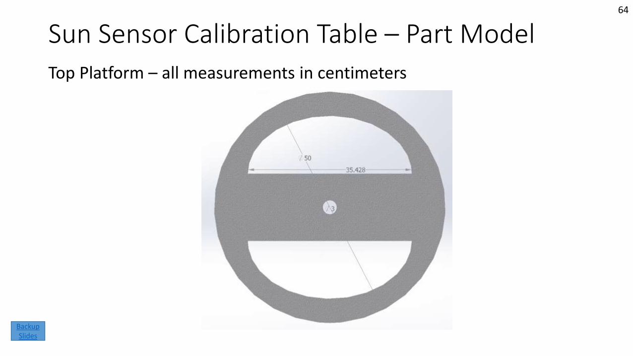
Sun Sensor Calibration Table – Part ModelTop Platform – all measurements in centimeters
64
Backup Slides
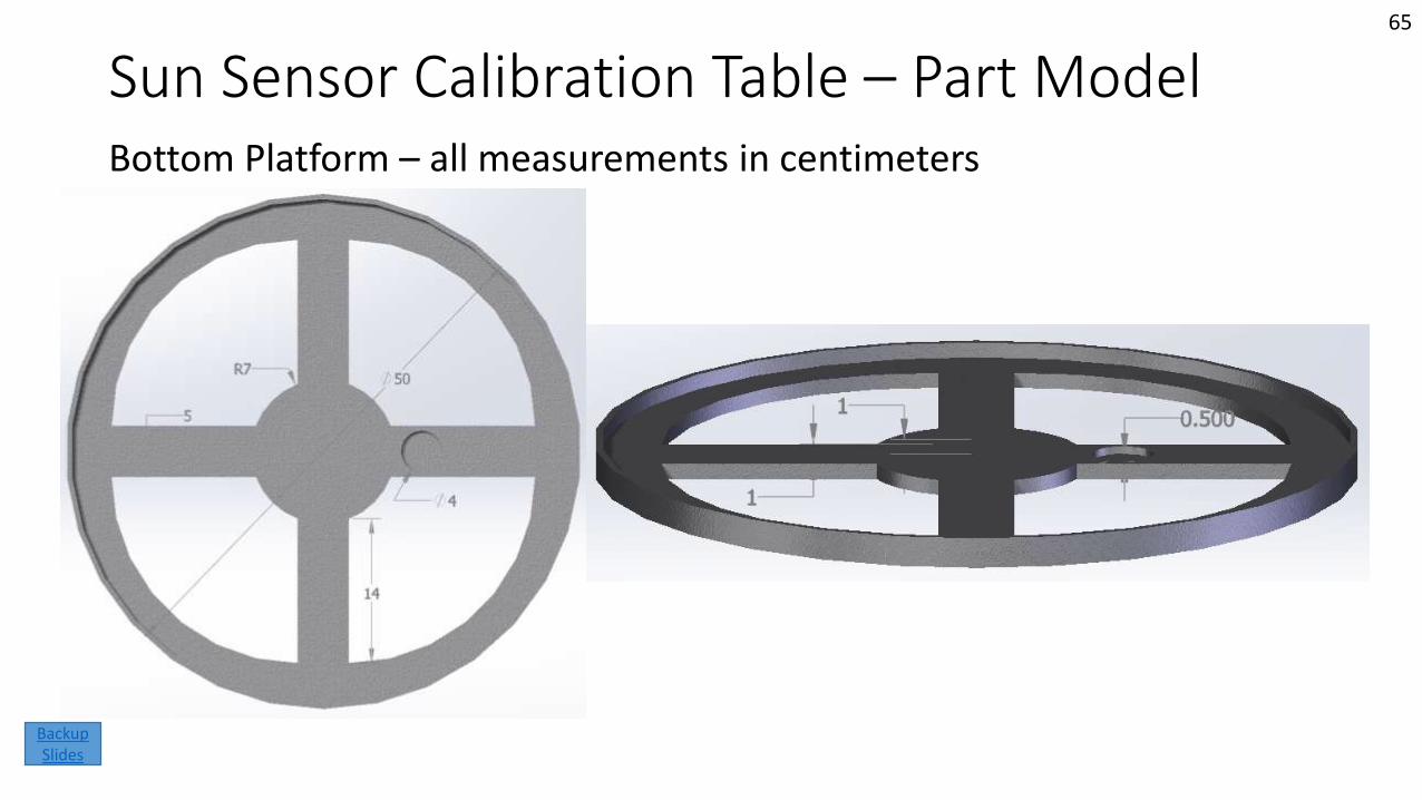
Sun Sensor Calibration Table – Part ModelBottom Platform – all measurements in centimeters
65
Backup Slides
Sun Sensor Calibration Table - Components
• 2x Aluminum disk, made from 50x50x3cm block
• 2x Aluminum gear, made from same Aluminum block
• Mechanical ball bearing
• Rotary magnetic encoder
• DC motor
• Analog to digital converter
• Digital LCD display
66
Backup Slides
Functional Requirement 3
• A turn table shall be delivered to the QB50 team that has resolution of 1 degree with accuracy of ±0.5°• DR.1 The turn table should have low reflectivity
• DR.1.1 The table will not have an albedo exceeding 5% in the visible light spectrum
• DR.2 The table shall sense angular position and display it to the user
• DR.3 A stepper motor shall be used to rotate the table
67
Backup Slides
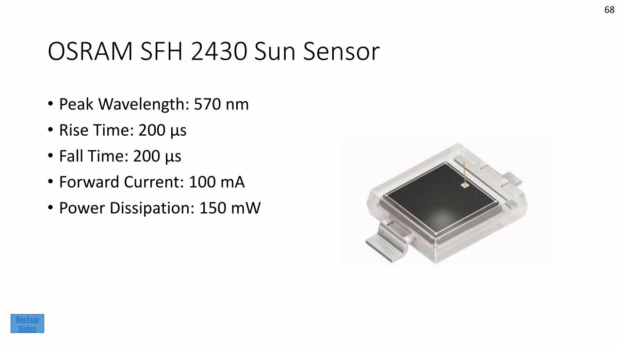
OSRAM SFH 2430 Sun Sensor
• Peak Wavelength: 570 nm
• Rise Time: 200 µs
• Fall Time: 200 µs
• Forward Current: 100 mA
• Power Dissipation: 150 mW
68
Backup Slides
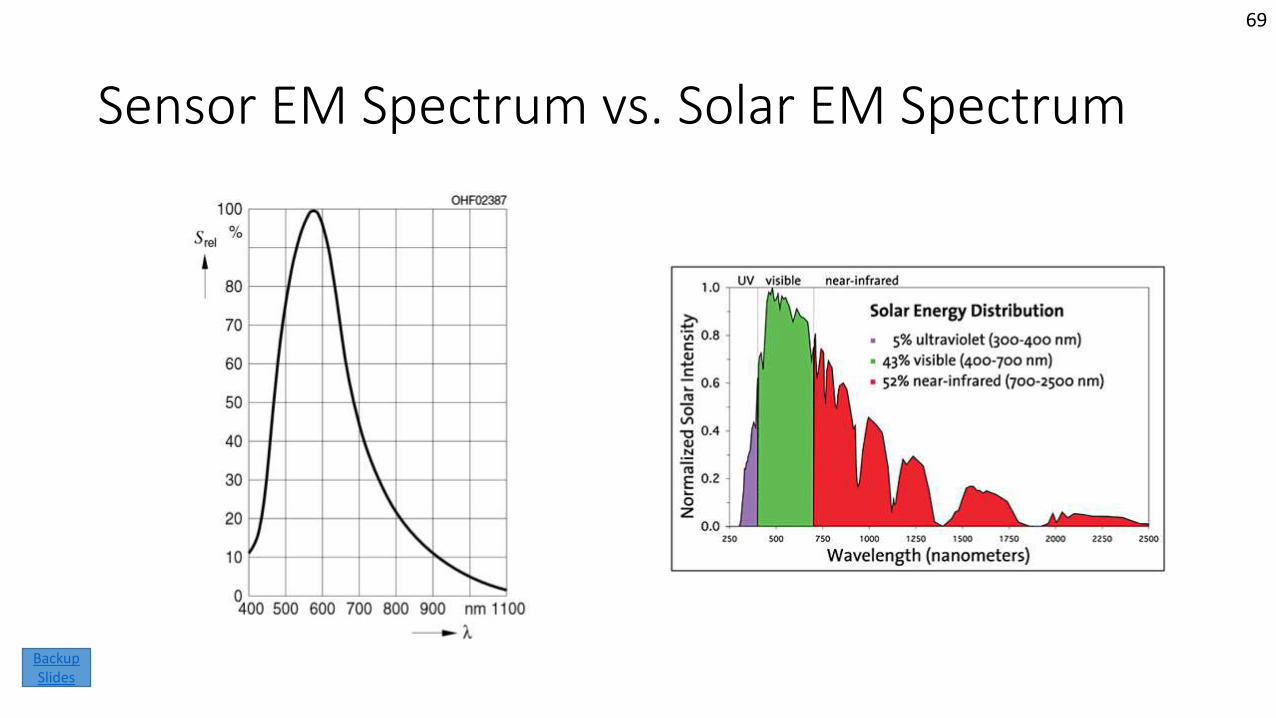
Sensor EM Spectrum vs. Solar EM Spectrum
69
Backup Slides
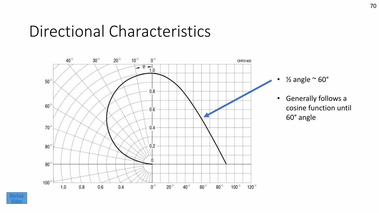
Directional Characteristics
• ½ angle ~ 60°
• Generally follows a cosine function until 60° angle
70
Backup Slides
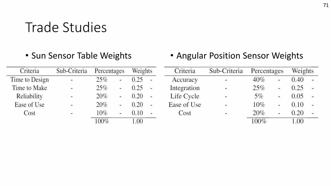
Trade Studies
• Sun Sensor Table Weights • Angular Position Sensor Weights
71
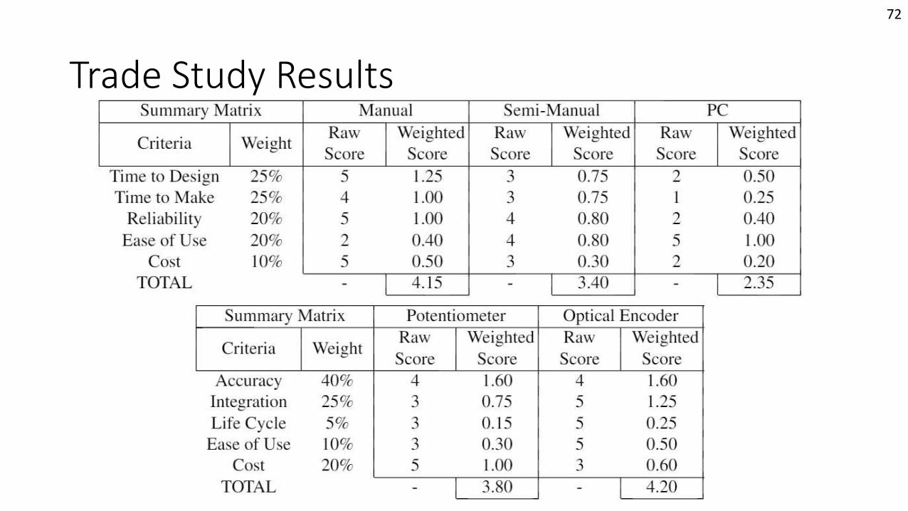
Trade Study Results
72
Helmholtz Cage Test
Mission Introduction
Project Description
Feasibility –Interface
Board
Feasibility –Helmholtz Cage Test
Backup Slides
Feasibility –Sun Sensor
Table
Status Summary
73
Backup Slides
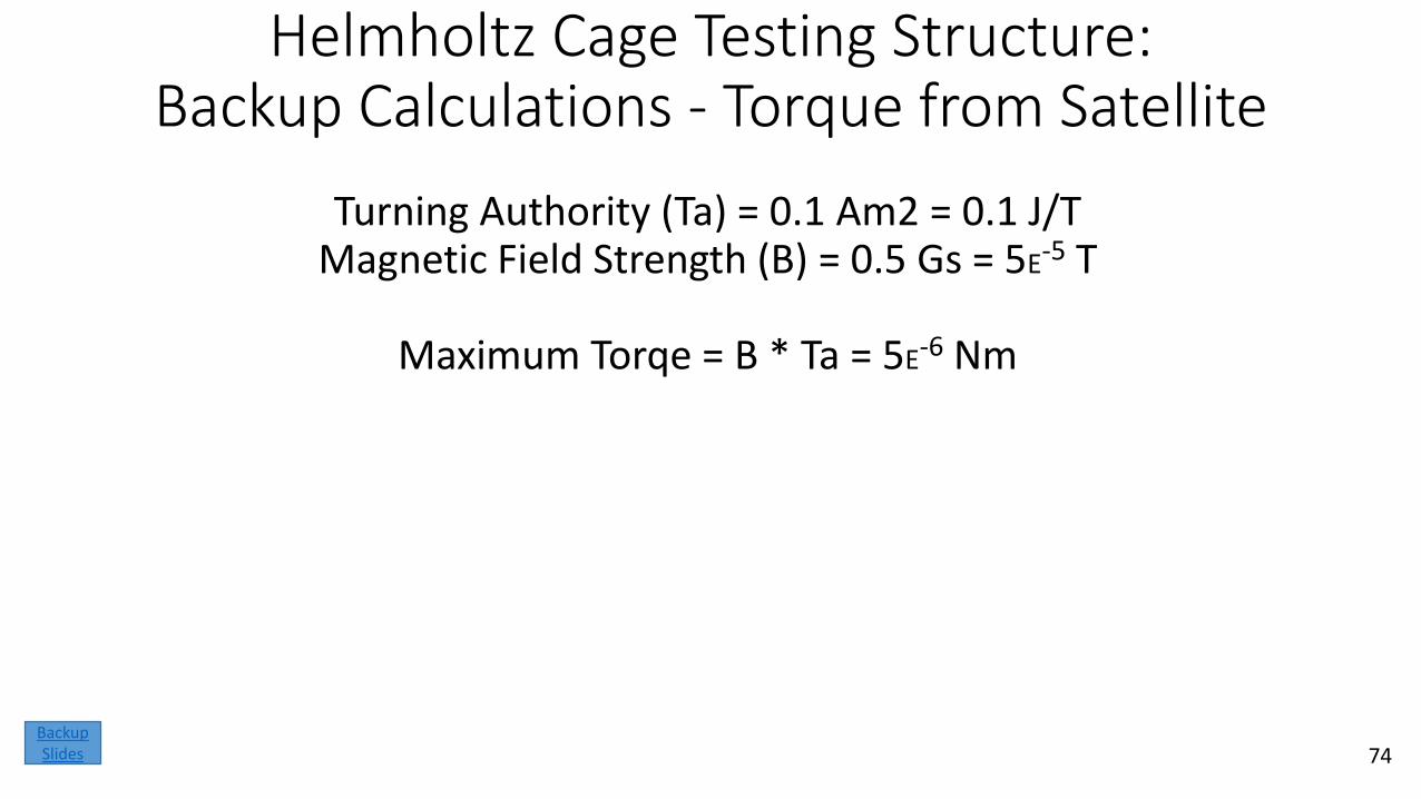
Helmholtz Cage Testing Structure:Backup Calculations - Torque from Satellite
Turning Authority (Ta) = 0.1 Am2 = 0.1 J/TMagnetic Field Strength (B) = 0.5 Gs = 5E-5 T
Maximum Torqe = B * Ta = 5E-6 Nm
74Backup Slides
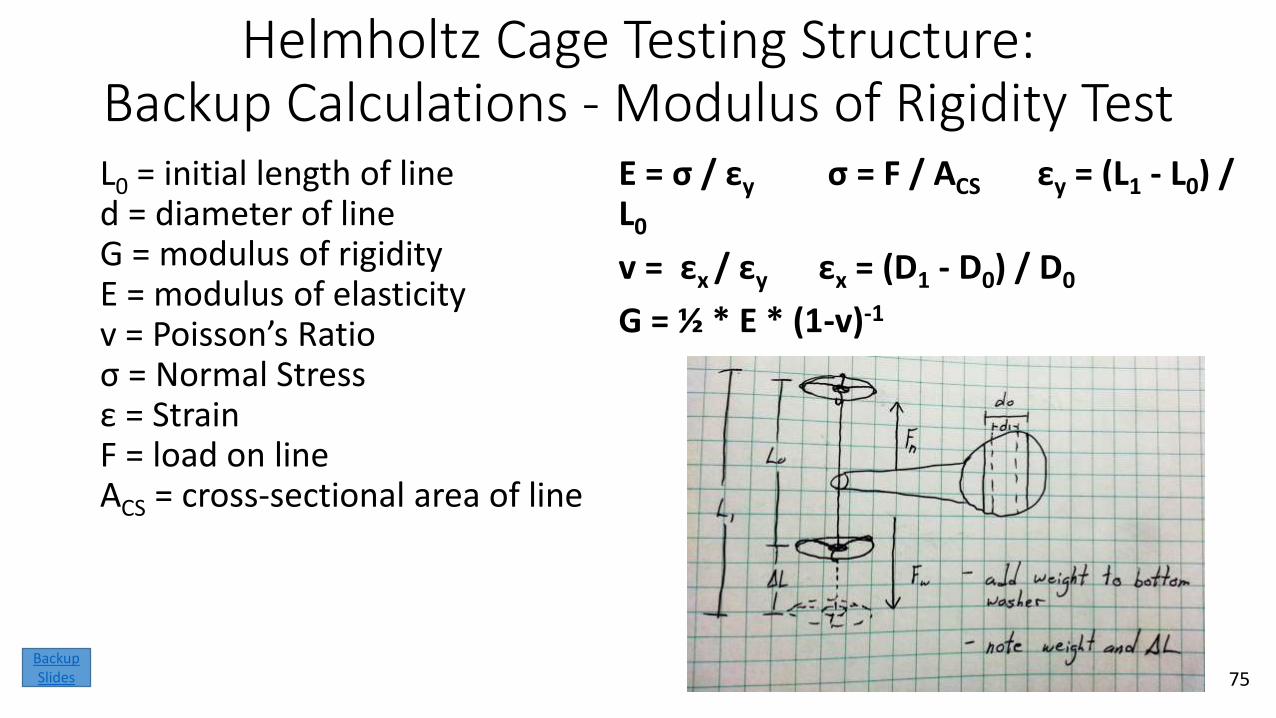
Helmholtz Cage Testing Structure:Backup Calculations - Modulus of Rigidity TestL0 = initial length of line d = diameter of lineG = modulus of rigidityE = modulus of elasticityv = Poisson’s Ratioσ = Normal Stressε = StrainF = load on lineACS = cross-sectional area of line
E = σ / εy σ = F / ACS εy = (L1 - L0) / L0
v = εx / εy εx = (D1 - D0) / D0
G = ½ * E * (1-v)-1
75Backup Slides
Helmholtz Cage Testing Structure:Backup Calculations - Modulus of Rigidity Test
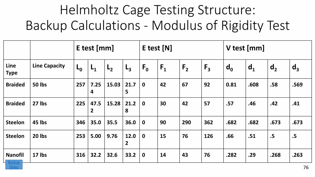
E test [mm] E test [N] V test [mm]
Line Type
Line Capacity L0 L1 L2 L3 F0 F1 F2 F3 d0 d1 d2 d3
Braided 50 lbs 257 7.254
15.03 21.75
0 42 67 92 0.81 .608 .58 .569
Braided 27 lbs 225 47.52
15.28 21.28
0 30 42 57 .57 .46 .42 .41
Steelon 45 lbs 346 35.0 35.5 36.0 0 90 290 362 .682 .682 .673 .673
Steelon 20 lbs 253 5.00 9.76 12.02
0 15 76 126 .66 .51 .5 .5
Nanofil 17 lbs 316 32.2 32.6 33.2 0 14 43 76 .282 .29 .268 .263
76Backup Slides
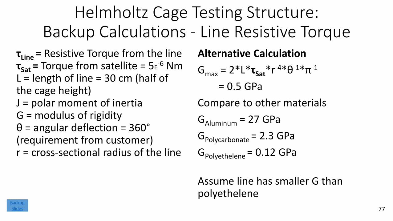
Helmholtz Cage Testing Structure:Backup Calculations - Line Resistive Torque
τLine = Resistive Torque from the lineτSat = Torque from satellite = 5E
-6 NmL = length of line = 30 cm (half of the cage height)J = polar moment of inertiaG = modulus of rigidityθ = angular deflection = 360°(requirement from customer)r = cross-sectional radius of the line
77
Alternative Calculation
Gmax = 2*L*τSat*r-4*θ-1*π-1
= 0.5 GPa
Compare to other materials
GAluminum = 27 GPa
GPolycarbonate = 2.3 GPa
GPolyethelene = 0.12 GPa
Assume line has smaller G than polyethelene
Backup Slides
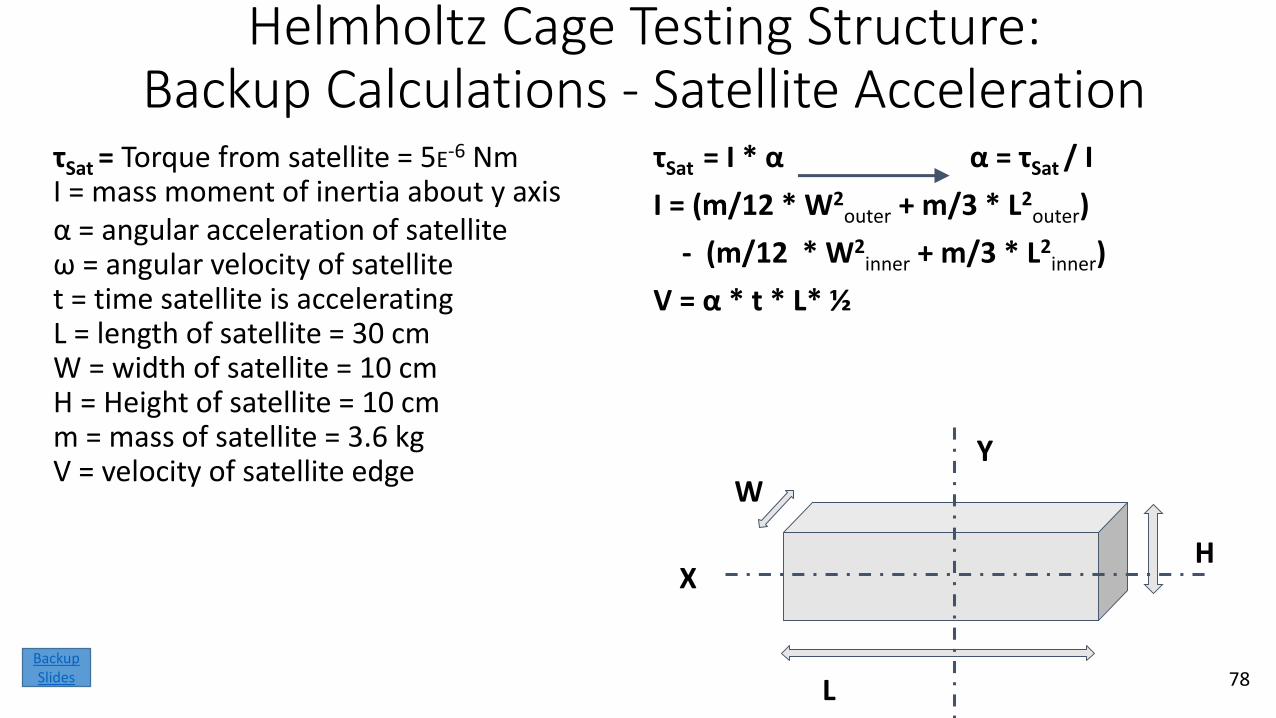
Helmholtz Cage Testing Structure:Backup Calculations - Satellite Acceleration
τSat = Torque from satellite = 5E-6 NmI = mass moment of inertia about y axisα = angular acceleration of satelliteω = angular velocity of satellitet = time satellite is acceleratingL = length of satellite = 30 cmW = width of satellite = 10 cmH = Height of satellite = 10 cmm = mass of satellite = 3.6 kgV = velocity of satellite edge
τSat = I * α α = τSat / I
I = (m/12 * W2outer + m/3 * L2
outer)
- (m/12 * W2inner + m/3 * L2
inner)
V = α * t * L* ½
L
W
H
Y
X
78Backup Slides
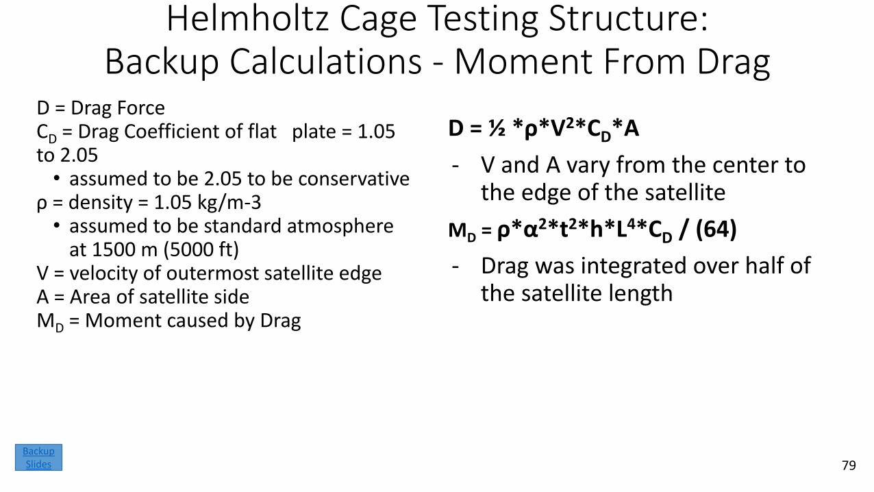
Helmholtz Cage Testing Structure:Backup Calculations - Moment From Drag
D = Drag Force CD = Drag Coefficient of flat plate = 1.05 to 2.05• assumed to be 2.05 to be conservative
ρ = density = 1.05 kg/m-3 • assumed to be standard atmosphere
at 1500 m (5000 ft)V = velocity of outermost satellite edgeA = Area of satellite sideMD = Moment caused by Drag
D = ½ *ρ*V2*CD*A
- V and A vary from the center to the edge of the satellite
MD = ρ*α2*t2*h*L4*CD / (64)
- Drag was integrated over half of the satellite length
79Backup Slides
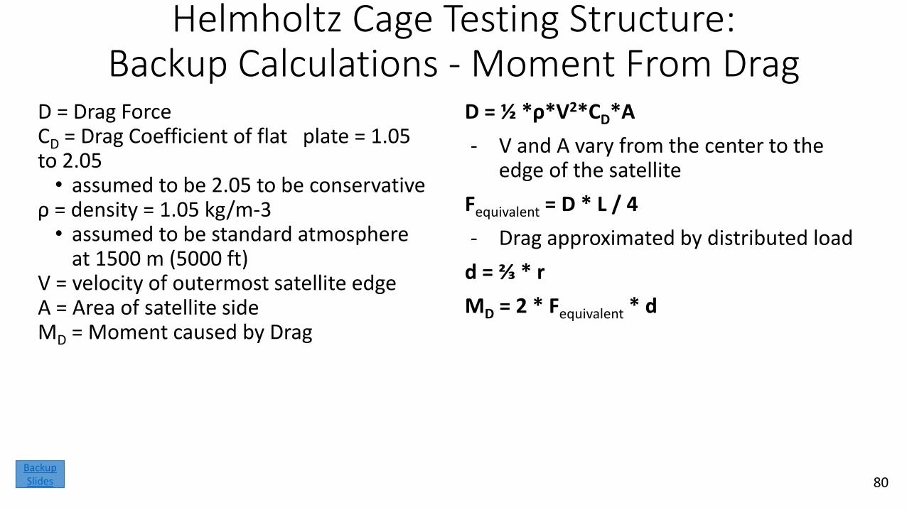
Helmholtz Cage Testing Structure:Backup Calculations - Moment From Drag
D = Drag Force CD = Drag Coefficient of flat plate = 1.05 to 2.05• assumed to be 2.05 to be conservative
ρ = density = 1.05 kg/m-3 • assumed to be standard atmosphere
at 1500 m (5000 ft)V = velocity of outermost satellite edgeA = Area of satellite sideMD = Moment caused by Drag
D = ½ *ρ*V2*CD*A
- V and A vary from the center to the edge of the satellite
Fequivalent = D * L / 4
- Drag approximated by distributed load
d = ⅔ * r
MD = 2 * Fequivalent * d
80Backup Slides
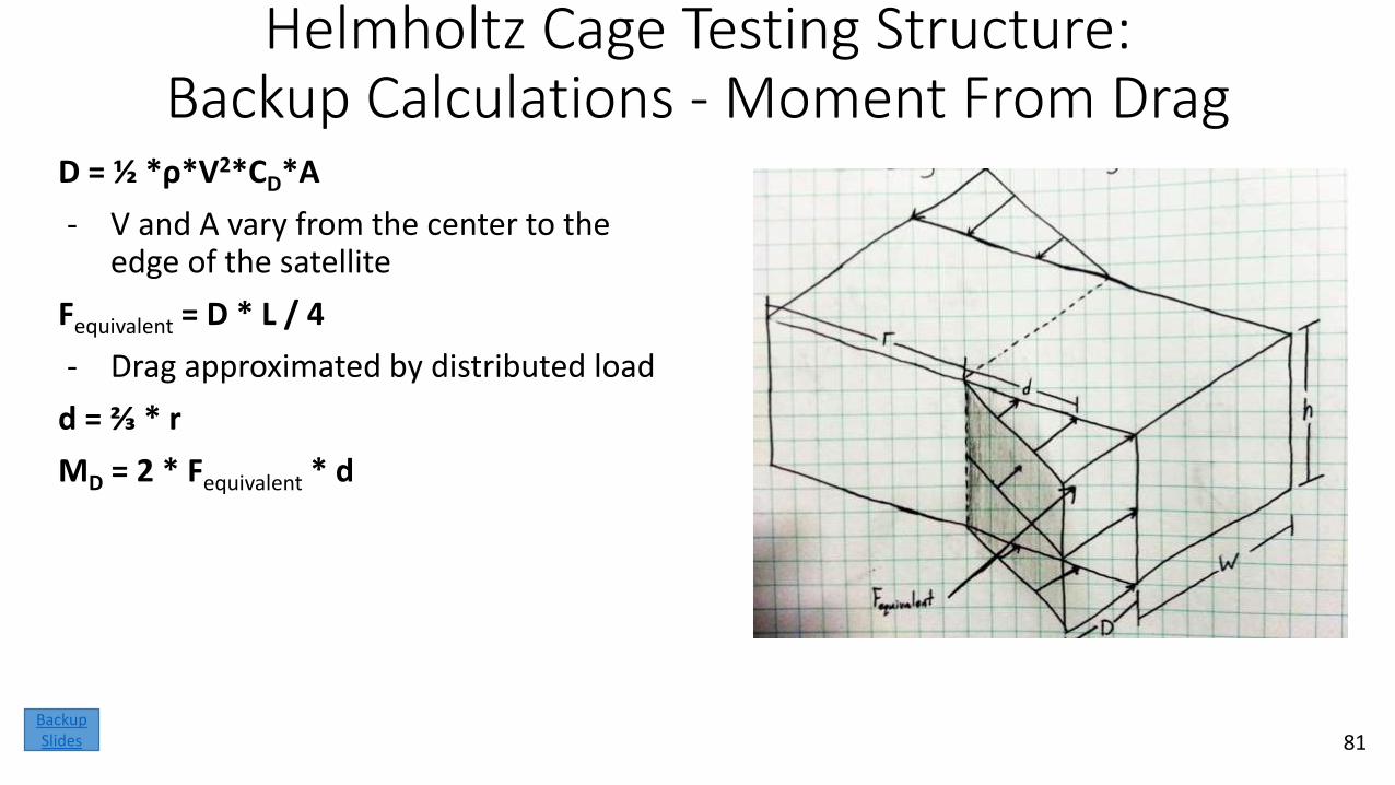
Helmholtz Cage Testing Structure:Backup Calculations - Moment From Drag
D = ½ *ρ*V2*CD*A
- V and A vary from the center to the edge of the satellite
Fequivalent = D * L / 4
- Drag approximated by distributed load
d = ⅔ * r
MD = 2 * Fequivalent * d
81Backup Slides
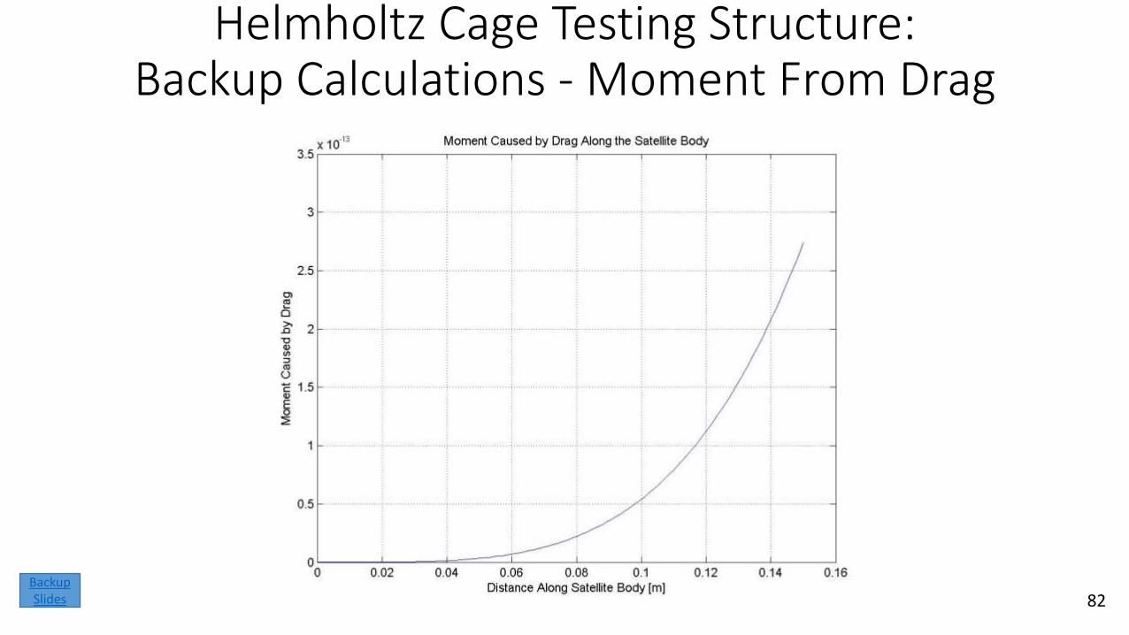
Helmholtz Cage Testing Structure:Backup Calculations - Moment From Drag
82Backup Slides
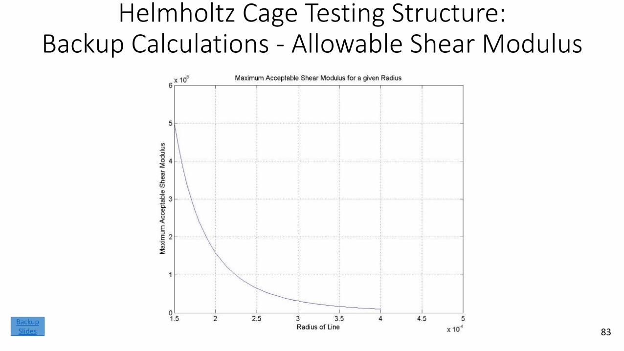
Helmholtz Cage Testing Structure:Backup Calculations - Allowable Shear Modulus
83Backup Slides
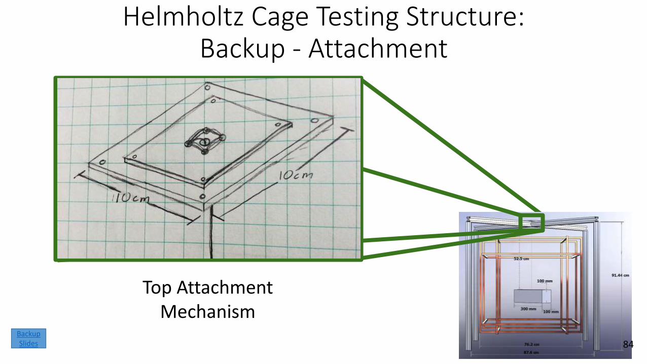
Helmholtz Cage Testing Structure:Backup - Attachment
Top Attachment Mechanism
84Backup Slides
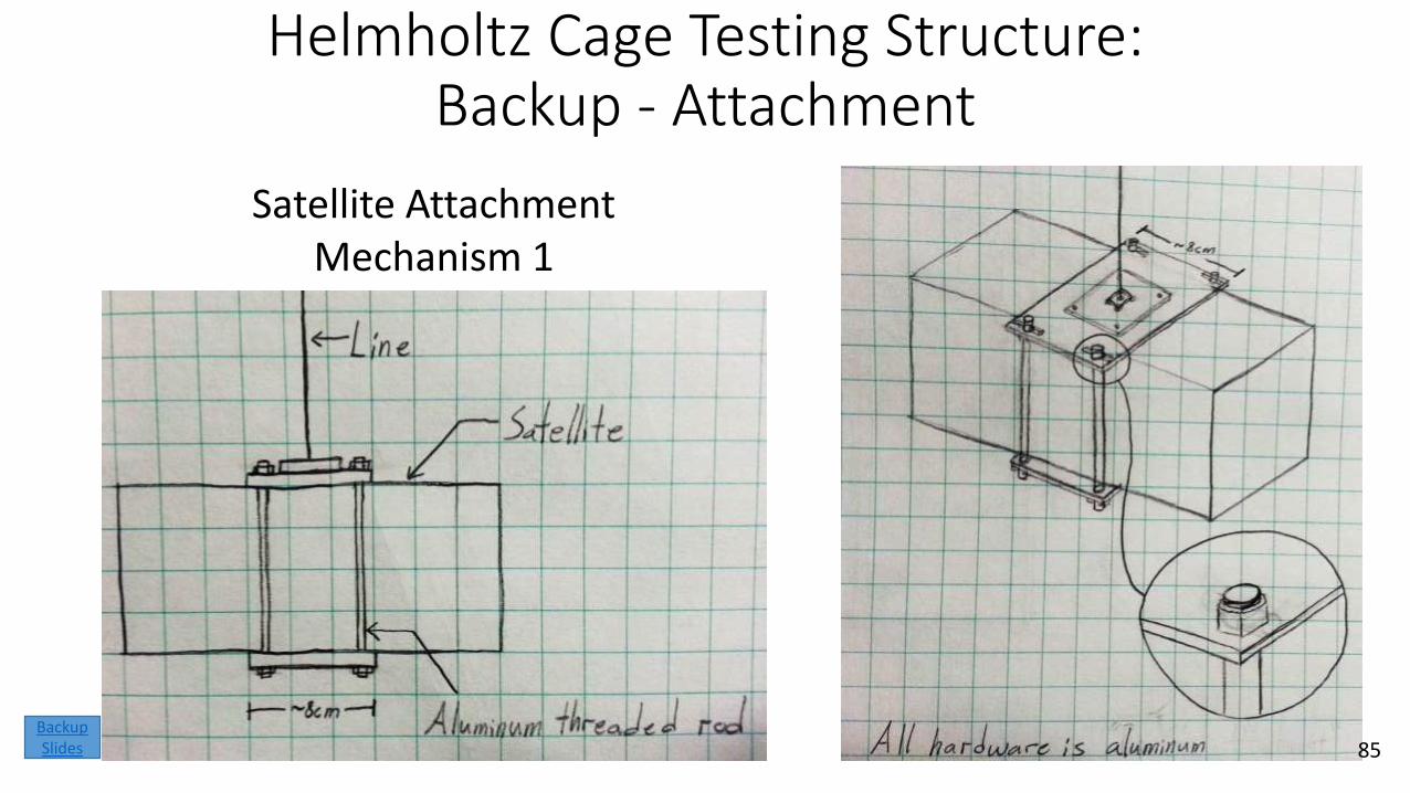
Helmholtz Cage Testing Structure:Backup - Attachment
Satellite Attachment Mechanism 1
85Backup Slides
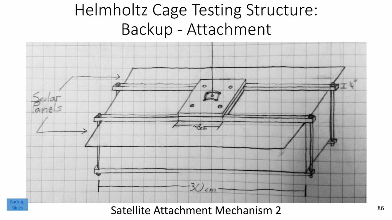
Helmholtz Cage Testing Structure:Backup - Attachment
Satellite Attachment Mechanism 2 86Backup Slides
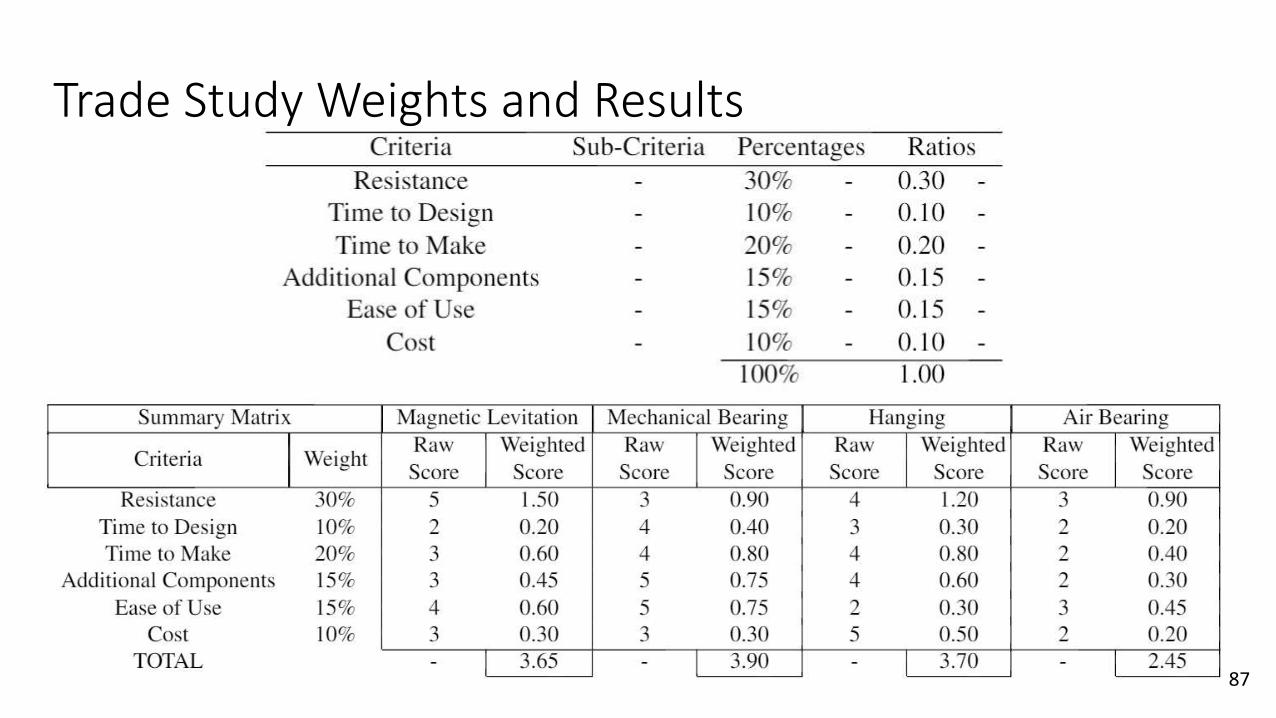
Trade Study Weights and Results
87
Logistics
Mission Introduction
Project Description
Feasibility –Interface
Board
Feasibility –Helmholtz Cage Test
Backup Slides
Feasibility –Sun Sensor
Table
Status Summary
88
Backup Slides
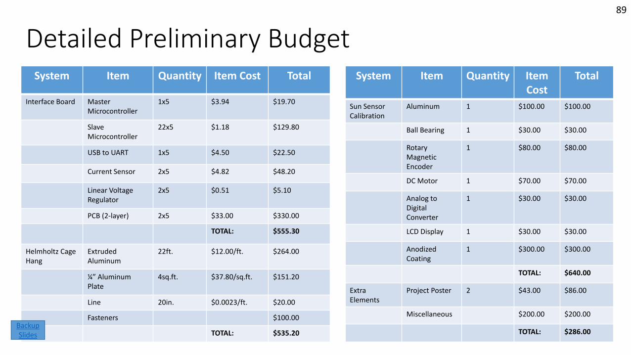
Detailed Preliminary BudgetSystem Item Quantity Item
CostTotal
Sun SensorCalibration
Aluminum 1 $100.00 $100.00
Ball Bearing 1 $30.00 $30.00
Rotary Magnetic Encoder
1 $80.00 $80.00
DC Motor 1 $70.00 $70.00
Analog to Digital Converter
1 $30.00 $30.00
LCD Display 1 $30.00 $30.00
AnodizedCoating
1 $300.00 $300.00
TOTAL: $640.00
Extra Elements
Project Poster 2 $43.00 $86.00
Miscellaneous $200.00 $200.00
TOTAL: $286.00
89
System Item Quantity Item Cost Total
Interface Board Master Microcontroller
1x5 $3.94 $19.70
Slave Microcontroller
22x5 $1.18 $129.80
USB to UART 1x5 $4.50 $22.50
Current Sensor 2x5 $4.82 $48.20
Linear Voltage Regulator
2x5 $0.51 $5.10
PCB (2-layer) 2x5 $33.00 $330.00
TOTAL: $555.30
Helmholtz Cage Hang
Extruded Aluminum
22ft. $12.00/ft. $264.00
¼” Aluminum Plate
4sq.ft. $37.80/sq.ft. $151.20
Line 20in. $0.0023/ft. $20.00
Fasteners $100.00
TOTAL: $535.20Backup Slides

![Chapter 2 Response to Harmonic Excitation · 2018. 1. 30. · 2 2 2 2 22 2 ( ) cos( tan ) ( ) (2 ) n p nn n X f x t t T]Z Z Z Z Z ]Z Z ZZ §· ¨¸ ©¹ Add homogeneous and particular](https://static.fdocument.org/doc/165x107/61035af8ca0a8c1a4026d7b4/chapter-2-response-to-harmonic-excitation-2018-1-30-2-2-2-2-22-2-cos-tan.jpg)