
Protek Foam Equipment
15
-
Upload
timotheos-vossos -
Category
Documents
-
view
352 -
download
7
description
Protek Foam Equipment
Transcript of Protek Foam Equipment

0062www.protekfire.com.tw [email protected]
PROTEK MANUFACTURING CORP.
PROTEK MANUFACTURING CORP.
R
CATALOGUE 218
��
FOA
M E
QU
IPM
ENT
FOAM EDUCTORS
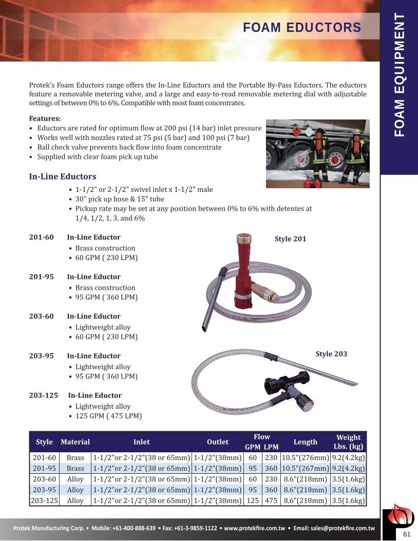
Protek's Foam Eductors range offers the In-Line Eductors and the Portable By-Pass Eductors. The eductors feature a removable metering valve, and a large and easy-to-read removable metering dial with adjustable settings of between 0% to 6%. Compatible with most foam concentrates.
Features:• Eductors are rated for optimum flow at 200 psi (14 bar) inlet pressure• Works well with nozzles rated at 75 psi (5 bar) and 100 psi (7 bar)• Ball check valve prevents back flow into foam concentrate• Supplied with clear foam pick up tube
In-Line Eductors • 1-1/2" or 2-1/2" swivel inlet x 1-1/2" male • 30" pick up hose & 15" tube • Pickup rate may be set at any position between 0% to 6% with detentes at 1/4, 1/2, 1, 3, and 6%
201-60 In-Line Eductor • Brass construction • 60 GPM ( 230 LPM)
201-95 In-Line Eductor • Brass construction • 95 GPM ( 360 LPM)
203-60 In-Line Eductor • Lightweight alloy • 60 GPM ( 230 LPM)
203-95 In-Line Eductor • Lightweight alloy • 95 GPM ( 360 LPM)
203-125 In-Line Eductor • Lightweight alloy • 125 GPM ( 475 LPM)
Style Material Inlet OutletFlow
LengthWeight
Lbs. (kg)GPM LPM201-60 Brass 1-1/2"or 2-1/2"(38 or 65mm) 1-1/2"(38mm) 60 230 10.5"(276mm) 9.2(4.2kg)201-95 Brass 1-1/2"or 2-1/2"(38 or 65mm) 1-1/2"(38mm) 95 360 10.5"(267mm) 9.2(4.2kg)203-60 Alloy 1-1/2"or 2-1/2"(38 or 65mm) 1-1/2"(38mm) 60 230 8.6"(218mm) 3.5(1.6kg)203-95 Alloy 1-1/2"or 2-1/2"(38 or 65mm) 1-1/2"(38mm) 95 360 8.6"(218mm) 3.5(1.6kg)
203-125 Alloy 1-1/2"or 2-1/2"(38 or 65mm) 1-1/2"(38mm) 125 475 8.6"(218mm) 3.5(1.6kg)
Style 201
Style 203
��
FOA
M E
QU
IPM
ENT
FOAM EDUCTORS
In-Line Eductor
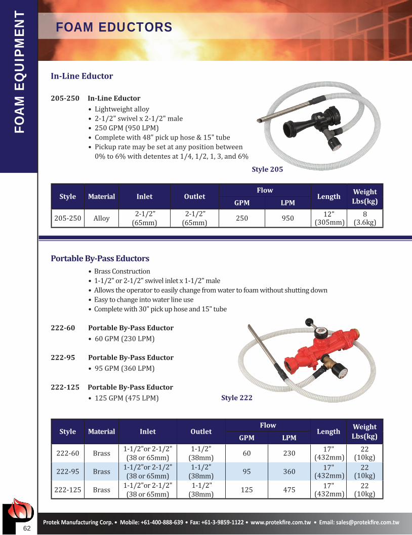
205-250 In-Line Eductor • Lightweight alloy • 2-1/2" swivel x 2-1/2" male • 250 GPM (950 LPM) • Complete with 48" pick up hose & 15" tube • Pickup rate may be set at any position between 0% to 6% with detentes at 1/4, 1/2, 1, 3, and 6%
Style Material Inlet OutletFlow
LengthWeightLbs(kg)GPM LPM
205-250 Alloy 2-1/2"(65mm)
2-1/2"(65mm) 250 950 12"
(305mm)8
(3.6kg)
Portable By-Pass Eductors • Brass Construction • 1-1/2" or 2-1/2" swivel inlet x 1-1/2" male • Allows the operator to easily change from water to foam without shutting down • Easy to change into water line use • Complete with 30" pick up hose and 15" tube
222-60 Portable By-Pass Eductor • 60 GPM (230 LPM)
222-95 Portable By-Pass Eductor • 95 GPM (360 LPM)
222-125 Portable By-Pass Eductor • 125 GPM (475 LPM)
Style Material Inlet OutletFlow
LengthWeightLbs(kg)GPM LPM
222-60 Brass 1-1/2"or 2-1/2"(38 or 65mm)
1-1/2"(38mm) 60 230 17"
(432mm)22
(10kg)
222-95 Brass 1-1/2"or 2-1/2"(38 or 65mm)
1-1/2"(38mm) 95 360 17"
(432mm)22
(10kg)
222-125 Brass 1-1/2"or 2-1/2"(38 or 65mm)
1-1/2"(38mm) 125 475 17"
(432mm)22
(10kg)
Style 205
Style 222
��
TEC
HN
ICA
L DA
TA FLOW & REACH DATA
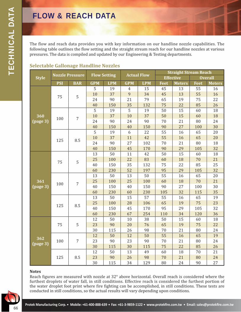
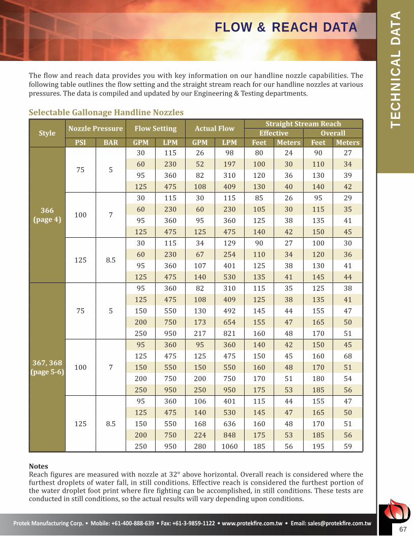
The flow and reach data provides you with key information on our handline nozzle capabilities. The following table outlines the flow setting and the straight stream reach for our handline nozzles at various pressures. The data is compiled and updated by our Engineering & Testing departments.
Selectable Gallonage Handline Nozzles
StyleNozzle Pressure Flow Setting Actual Flow
Straight Stream ReachEffective Overall
PSI BAR GPM LPM GPM LPM Feet Meters Feet Meters
360(page 3)
75 5
5 19 4 15 45 13 55 1610 37 9 34 45 13 55 1624 90 21 79 65 19 75 2240 150 35 132 75 22 85 26
100 7
5 19 5 19 50 15 60 1810 37 10 37 50 15 60 1824 90 24 90 70 21 80 2440 150 40 150 90 27 100 30
125 8.5
5 19 6 22 55 16 65 2010 37 11 42 55 16 65 2024 90 27 102 70 21 80 1840 150 45 170 90 29 105 32
361(page 3)
75 5
13 50 11 42 50 15 60 1825 100 22 83 60 18 70 2140 150 35 132 75 22 85 2560 230 52 197 95 29 105 32
100 7
13 50 13 50 55 16 65 2025 100 25 100 60 18 70 2140 150 40 150 90 27 100 3060 230 60 230 105 32 115 35
125 8.5
13 50 15 57 55 16 65 1925 100 28 106 65 19 75 2340 150 45 170 95 29 105 3260 230 67 254 110 34 120 36
362(page 3)
75 512 50 10 38 50 15 60 1823 90 20 76 65 19 75 2230 115 26 98 70 21 80 24
100 712 50 12 50 55 16 65 1923 90 23 90 70 21 80 2430 115 30 115 75 22 85 26
125 8.512 50 13 49 60 18 70 2123 90 26 98 70 21 80 2430 115 34 129 80 24 90 27
NotesReach figures are measured with nozzle at 32° above horizontal. Overall reach is considered where the furthest droplets of water fall, in still conditions. Effective reach is considered the furthest portion of the water droplet foot print where fire fighting can be accomplished, in still conditions. These tests are conducted in still conditions, so the actual results will vary depending upon conditions.
��
TEC
HN
ICA
L DA
TAFLOW & REACH DATA
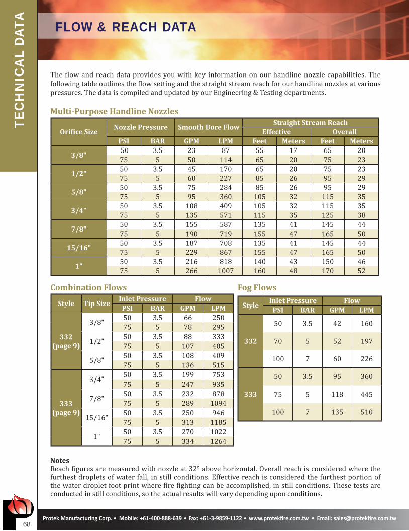
The flow and reach data provides you with key information on our handline nozzle capabilities. The following table outlines the flow setting and the straight stream reach for our handline nozzles at various pressures. The data is compiled and updated by our Engineering & Testing departments.
Selectable Gallonage Handline Nozzles
StyleNozzle Pressure Flow Setting Actual Flow
Straight Stream ReachEffective Overall
PSI BAR GPM LPM GPM LPM Feet Meters Feet Meters
366(page 4)
75 5
30 115 26 98 80 24 90 2760 230 52 197 100 30 110 3495 360 82 310 120 36 130 39
125 475 108 409 130 40 140 42
100 7
30 115 30 115 85 26 95 2960 230 60 230 105 30 115 3595 360 95 360 125 38 135 41
125 475 125 475 140 42 150 45
125 8.5
30 115 34 129 90 27 100 3060 230 67 254 110 34 120 3695 360 107 401 125 38 130 41
125 475 140 530 135 41 145 44
367, 368(page 5-6)
75 5
95 360 82 310 115 35 125 38125 475 108 409 125 38 135 41150 550 130 492 145 44 155 47200 750 173 654 155 47 165 50250 950 217 821 160 48 170 51
100 7
95 360 95 360 140 42 150 45125 475 125 475 150 45 160 68150 550 150 550 160 48 170 51200 750 200 750 170 51 180 54250 950 250 950 175 53 185 56
125 8.5
95 360 106 401 115 44 155 47125 475 140 530 145 47 165 50150 550 168 636 160 48 170 51200 750 224 848 175 53 185 56250 950 280 1060 185 56 195 59
NotesReach figures are measured with nozzle at 32° above horizontal. Overall reach is considered where the furthest droplets of water fall, in still conditions. Effective reach is considered the furthest portion of the water droplet foot print where fire fighting can be accomplished, in still conditions. These tests are conducted in still conditions, so the actual results will vary depending upon conditions.
��
TEC
HN
ICA
L DA
TA FLOW & REACH DATA
The flow and reach data provides you with key information on our handline nozzle capabilities. The following table outlines the flow setting and the straight stream reach for our handline nozzles at various pressures. The data is compiled and updated by our Engineering & Testing departments.
Multi-Purpose Handline Nozzles
Orifice SizeNozzle Pressure Smooth Bore Flow
Straight Stream ReachEffective Overall
PSI BAR GPM LPM Feet Meters Feet Meters
3/8" 50 3.5 23 87 55 17 65 2075 5 50 114 65 20 75 23
1/2"50 3.5 45 170 65 20 75 2375 5 60 227 85 26 95 29
5/8"50 3.5 75 284 85 26 95 2975 5 95 360 105 32 115 35
3/4"50 3.5 108 409 105 32 115 3575 5 135 571 115 35 125 38
7/8"50 3.5 155 587 135 41 145 4475 5 190 719 155 47 165 50
15/16"50 3.5 187 708 135 41 145 4475 5 229 867 155 47 165 50
1"50 3.5 216 818 140 43 150 4675 5 266 1007 160 48 170 52
Combination Flows Fog Flows
Style Tip SizeInlet Pressure FlowPSI BAR GPM LPM
332(page 9)
3/8" 50 3.5 66 25075 5 78 295
1/2" 50 3.5 88 33375 5 107 405
5/8" 50 3.5 108 40975 5 136 515
333(page 9)
3/4" 50 3.5 199 75375 5 247 935
7/8" 50 3.5 232 87875 5 289 1094
15/16" 50 3.5 250 94675 5 313 1185
1" 50 3.5 270 102275 5 334 1264
NotesReach figures are measured with nozzle at 32° above horizontal. Overall reach is considered where the furthest droplets of water fall, in still conditions. Effective reach is considered the furthest portion of the water droplet foot print where fire fighting can be accomplished, in still conditions. These tests are conducted in still conditions, so the actual results will vary depending upon conditions.
StyleInlet Pressure Flow
PSI BAR GPM LPM
332
50 3.5 42 160
70 5 52 197
100 7 60 226
333
50 3.5 95 360
75 5 118 445
100 7 135 510
��
TEC
HN
ICA
L DA
TAFLOW & REACH DATA
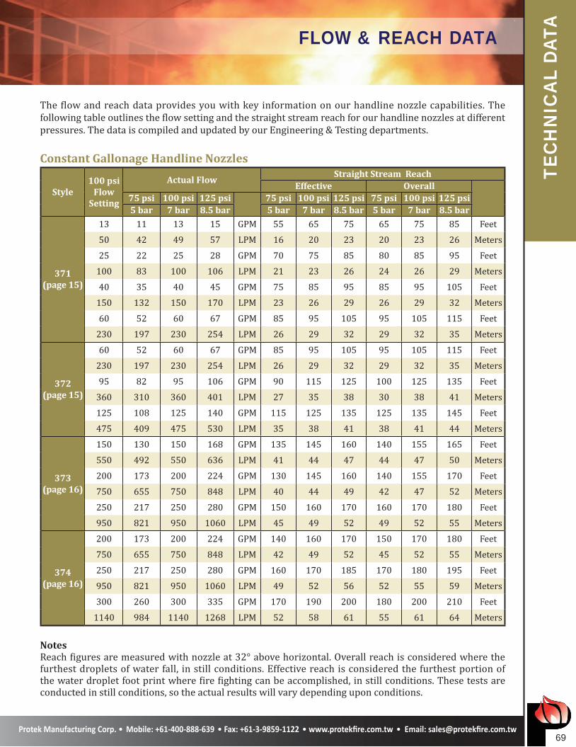
The flow and reach data provides you with key information on our handline nozzle capabilities. The following table outlines the flow setting and the straight stream reach for our handline nozzles at different pressures. The data is compiled and updated by our Engineering & Testing departments.
Constant Gallonage Handline Nozzles
Style100 psi
FlowSetting
Actual FlowStraight Stream Reach
Effective Overall75 psi 100 psi 125 psi 75 psi 100 psi 125 psi 75 psi 100 psi 125 psi5 bar 7 bar 8.5 bar 5 bar 7 bar 8.5 bar 5 bar 7 bar 8.5 bar
371(page 15)
13 11 13 15 GPM 55 65 75 65 75 85 Feet
50 42 49 57 LPM 16 20 23 20 23 26 Meters
25 22 25 28 GPM 70 75 85 80 85 95 Feet
100 83 100 106 LPM 21 23 26 24 26 29 Meters
40 35 40 45 GPM 75 85 95 85 95 105 Feet
150 132 150 170 LPM 23 26 29 26 29 32 Meters
60 52 60 67 GPM 85 95 105 95 105 115 Feet
230 197 230 254 LPM 26 29 32 29 32 35 Meters
372(page 15)
60 52 60 67 GPM 85 95 105 95 105 115 Feet
230 197 230 254 LPM 26 29 32 29 32 35 Meters
95 82 95 106 GPM 90 115 125 100 125 135 Feet
360 310 360 401 LPM 27 35 38 30 38 41 Meters
125 108 125 140 GPM 115 125 135 125 135 145 Feet
475 409 475 530 LPM 35 38 41 38 41 44 Meters
373(page 16)
150 130 150 168 GPM 135 145 160 140 155 165 Feet
550 492 550 636 LPM 41 44 47 44 47 50 Meters
200 173 200 224 GPM 130 145 160 140 155 170 Feet
750 655 750 848 LPM 40 44 49 42 47 52 Meters
250 217 250 280 GPM 150 160 170 160 170 180 Feet
950 821 950 1060 LPM 45 49 52 49 52 55 Meters
374(page 16)
200 173 200 224 GPM 140 160 170 150 170 180 Feet
750 655 750 848 LPM 42 49 52 45 52 55 Meters
250 217 250 280 GPM 160 170 185 170 180 195 Feet
950 821 950 1060 LPM 49 52 56 52 55 59 Meters
300 260 300 335 GPM 170 190 200 180 200 210 Feet
1140 984 1140 1268 LPM 52 58 61 55 61 64 Meters
NotesReach figures are measured with nozzle at 32° above horizontal. Overall reach is considered where the furthest droplets of water fall, in still conditions. Effective reach is considered the furthest portion of the water droplet foot print where fire fighting can be accomplished, in still conditions. These tests are conducted in still conditions, so the actual results will vary depending upon conditions.
�0
TEC
HN
ICA
L DA
TA COMPATIBILITY CHART
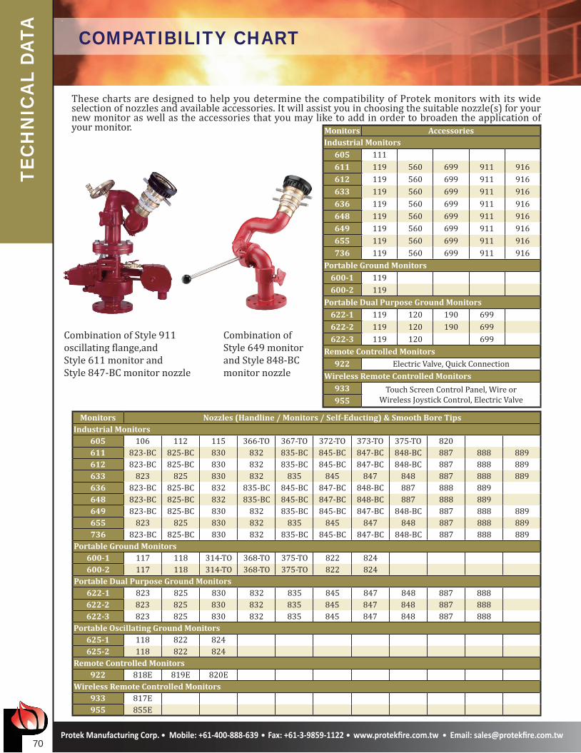
These charts are designed to help you determine the compatibility of Protek monitors with its wide selection of nozzles and available accessories. It will assist you in choosing the suitable nozzle(s) for your new monitor as well as the accessories that you may like to add in order to broaden the application of your monitor.
Monitors Nozzles (Handline / Monitors / Self-Educting) & Smooth Bore TipsIndustrial Monitors
605 106 112 115 366-TO 367-TO 372-TO 373-TO 375-TO 820611 823-BC 825-BC 830 832 835-BC 845-BC 847-BC 848-BC 887 888 889612 823-BC 825-BC 830 832 835-BC 845-BC 847-BC 848-BC 887 888 889633 823 825 830 832 835 845 847 848 887 888 889636 823-BC 825-BC 832 835-BC 845-BC 847-BC 848-BC 887 888 889648 823-BC 825-BC 832 835-BC 845-BC 847-BC 848-BC 887 888 889649 823-BC 825-BC 830 832 835-BC 845-BC 847-BC 848-BC 887 888 889655 823 825 830 832 835 845 847 848 887 888 889736 823-BC 825-BC 830 832 835-BC 845-BC 847-BC 848-BC 887 888 889
Portable Ground Monitors600-1 117 118 314-TO 368-TO 375-TO 822 824600-2 117 118 314-TO 368-TO 375-TO 822 824
Portable Dual Purpose Ground Monitors622-1 823 825 830 832 835 845 847 848 887 888622-2 823 825 830 832 835 845 847 848 887 888622-3 823 825 830 832 835 845 847 848 887 888
Portable Oscillating Ground Monitors625-1 118 822 824625-2 118 822 824
Remote Controlled Monitors922 818E 819E 820E
Wireless Remote Controlled Monitors933 817E955 855E
Monitors AccessoriesIndustrial Monitors
605 111611 119 560 699 911 916612 119 560 699 911 916633 119 560 699 911 916636 119 560 699 911 916648 119 560 699 911 916649 119 560 699 911 916655 119 560 699 911 916736 119 560 699 911 916
Portable Ground Monitors600-1 119600-2 119
Portable Dual Purpose Ground Monitors622-1 119 120 190 699622-2 119 120 190 699622-3 119 120 699
Remote Controlled Monitors922 Electric Valve, Quick Connection
Wireless Remote Controlled Monitors933 Touch Screen Control Panel, Wire or
Wireless Joystick Control, Electric Valve955
Combination of Style 911 oscillating flange,and Style 611 monitor andStyle 847-BC monitor nozzle
Combination of Style 649 monitor and Style 848-BC monitor nozzle
��
TEC
HN
ICA
L DA
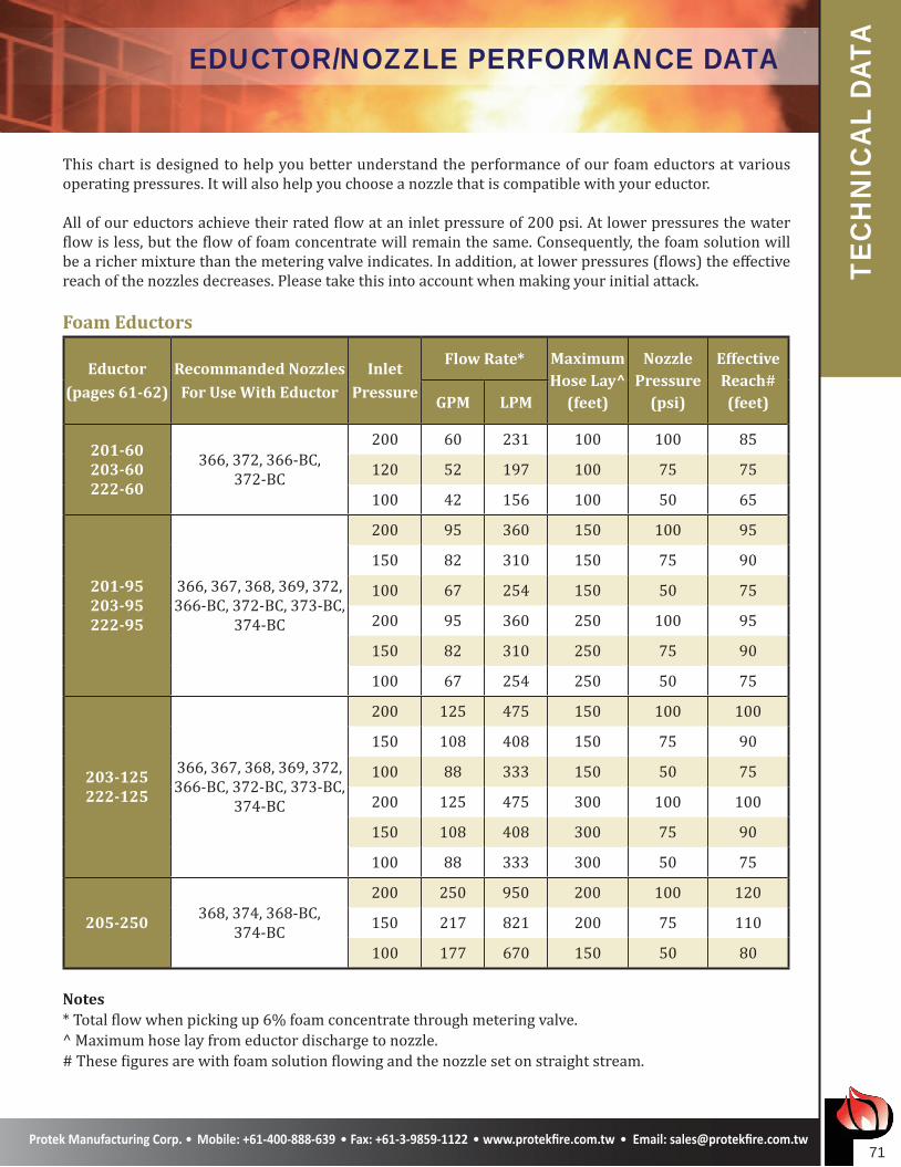
TAEDUCTOR/NOZZLE PERFORMANCE DATA
This chart is designed to help you better understand the performance of our foam eductors at various operating pressures. It will also help you choose a nozzle that is compatible with your eductor.
All of our eductors achieve their rated flow at an inlet pressure of 200 psi. At lower pressures the water flow is less, but the flow of foam concentrate will remain the same. Consequently, the foam solution will be a richer mixture than the metering valve indicates. In addition, at lower pressures (flows) the effective reach of the nozzles decreases. Please take this into account when making your initial attack.
Foam Eductors
Eductor(pages 61-62)
Recommanded NozzlesFor Use With Eductor
InletPressure
Flow Rate* MaximumHose Lay^
(feet)
NozzlePressure
(psi)
EffectiveReach#(feet)GPM LPM
201-60203-60222-60
366, 372, 366-BC, 372-BC
200 60 231 100 100 85
120 52 197 100 75 75
100 42 156 100 50 65
201-95203-95222-95
366, 367, 368, 369, 372, 366-BC, 372-BC, 373-BC,
374-BC
200 95 360 150 100 95
150 82 310 150 75 90
100 67 254 150 50 75
200 95 360 250 100 95
150 82 310 250 75 90
100 67 254 250 50 75
203-125222-125
366, 367, 368, 369, 372, 366-BC, 372-BC, 373-BC,
374-BC
200 125 475 150 100 100
150 108 408 150 75 90
100 88 333 150 50 75
200 125 475 300 100 100
150 108 408 300 75 90
100 88 333 300 50 75
205-250368, 374, 368-BC,
374-BC
200 250 950 200 100 120
150 217 821 200 75 110
100 177 670 150 50 80
Notes* Total flow when picking up 6% foam concentrate through metering valve.^ Maximum hose lay from eductor discharge to nozzle.# These figures are with foam solution flowing and the nozzle set on straight stream.
��
TEC
HN
ICA
L DA
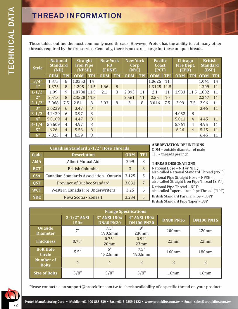
TA THREAD INFORMATION
These tables outline the most commonly used threads. However, Protek has the ability to cut many other threads required by the fire service. Generally, there is no extra charge for these unique threads.
Style
NationalStandard
(NH)
StraightIron Pipe
(NPSH)
New York FD
(FDNY)
New YorkCorp(NYC)
Pacific Coast(PCT)
ChicagoFire Dept.
(CFD)
BritishStandard
(BSP)ODM TPI ODM TPI ODM TPI ODM TPI ODM TPI ODM TPI ODM TPI
3/4" 1.375 8 1.0353 14 1.0625 11 1.041 141" 1.375 8 1.295 11.5 1.66 8 1.3125 11.5 1.309 11
1-1/2" 1.99 9 1.8788 11.5 2.1 8 2.093 11 2.1 11 1.933 11.5 1.882 112" 2.515 8 2.3528 11.5 2.561 11 2.55 10 2.347 11
2-1/2" 3.068 7.5 2.841 8 3.03 8 3 8 3.046 7.5 2.99 7.5 2.96 113" 3.6239 6 3.47 8 3.46 11
3-1/2" 4.2439 6 3.97 8 4.052 84" 5.0109 4 4.47 8 5.011 4 4.45 11
4-1/4" 5.7609 4 4.97 8 5.761 4 4.95 115" 6.26 4 5.53 8 6.26 4 5.45 116" 7.025 4 6.59 8 6.45 11
Canadian Standard 2-1/2" Hose Threads
Code Description ODM TPI
AMA Albert Mutual Aid 2.99 8BCT British Columbia 3 8CSA Canadian Standards Association - Ontario 3.125 5QST Province of Quebec Standard 3.031 7WCT Western Canada Fire Underwriters 3.25 6NDC Nova Scotia - Zones 1 3.234 5
Flange Specifications2-1/2" ANSI
150#3" ANSI 150#DN80 PN20
4" ANSI 150#DN100 PN20
DN80 PN16 DN100 PN16
OutsideDiameter
7" 7.5"190.5mm
9"230mm 200mm 220mm
Thickness 0.75" 0.75"20mm
0.94"23mm 22mm 22mm
Bolt HoleCircle
5.5" 6"152.5mm
7.5"190.5mm 160mm 180mm
Number ofBolts
4 4 8 8 8
Size of Bolts 5/8" 5/8" 5/8" 16mm 16mm
Please contact us on [email protected] to check availability of a specific thread on your product.
ABBREVIATION DEFINITIONSODM – outside diameter of maleTPI – threads per inch
THREAD DESIGNATIONSNational Hose – NH or NHT; also called National Standard Thread (NST)National Pipe Straight Hose – NPSH; also called Straight Iron Pipe Thread (SIPT)National Pipe Thread – NPT; also called Tapered Iron Pipe Thread (TIPT)British Standard Parallel Pipe – BSPPBritish Standard Pipe Taper – BSP
��
TEC
HN
ICA
L DA
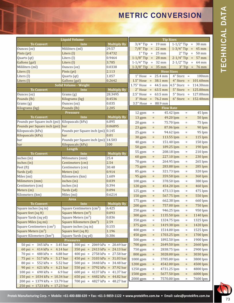
TAMETRIC CONVERSION
Liquid VolumeTo Convert Into Multiply By
Ounces (oz) Mililiters (ml) 29.57Pints (pt) Liters (l) 0.4732Quarts (qt) Liters (l) 0.9464Gallons (gal) Liters (l) 3.785Mililiters (ml) Ounces (oz) 0.0338Liters (l) Pints (pt) 2.113Liters (l) Quarts (qt) 1.057Liters (l) Gallons (gal) 0.2642
Solid Volume - WeightTo Convert Into Multiply By
Ounces (oz) Grams (g) 28.3495Pounds (lb) Kilograms (kg) 0.4536Grams (g) Ounces (oz) 0.035Kilograms (kg) Pounds (lb) 2.205
PressureTo Convert Into Multiply By
Pounds per Square inch (psi) Kilopascals (kPa) 6.895Pounds per Square inch (psi) bar 0.06895Kilopascals (kPa) Pounds per Square inch (psi) 0.145Kilopascals (kPa) bar 0.01bar Pounds per Square inch (psi) 14.503bar Kilopascals (kPa) 100
LengthTo Convert Into Multiply By
inches (in) Milimeters (mm) 25.4inches (in) Centimeters (cm) 2.54Feet (ft) Centimeters (cm) 30.48Yards (yd) Meters (m) 0.914Miles (mi) Kilometers (km) 1.609Milimeters (mm) inches (in) 0.039Centimeters (cm) inches (in) 0.394Meters (m) Yards (yd) 0.094Kilometers (km) Miles (mi) 0.6214
AreaTo Convert Into Multiply By
Square inches (sq in) Square Centimeters (cm²) 6.425Square feet (sq ft) Square Meters (m²) 0.093Square Yards (sq yd) Square Meters (m²) 0.836Square Miles (sq mi) Square Kilometers (km²) 2.59Square Centimeters (cm²) Square inches (sq in) 0.155Square Meters (m²) Square feet (sq ft) 1.196Square Kilometers (km²) Square Yards (sq yd) 0.386
Pressures 50 psi = 345 kPa = 3.45 bar 300 psi = 2069 kPa = 20.69 bar 60 psi = 414 kPa = 4.14 bar 350 psi = 2413 kPa = 24.13 bar 70 psi = 488 kPa = 4.88 bar 400 psi = 2758 kPa = 27.58 bar 75 psi = 517 kPa = 5.17 bar 450 psi = 3103 kPa = 31.03 bar 80 psi = 552 kPa = 5.52 bar 500 psi = 3448 kPa = 34.48 bar 90 psi = 621 kPa = 6.21 bar 550 psi = 3792 kPa = 37.92 bar 100 psi = 690 kPa = 6.9 bar 600 psi = 4137 kPa = 41.37 bar 150 psi = 1034 kPa = 10.34 bar 650 psi = 4482 kPa = 44.82 bar 200 psi = 1379 kPa = 13.79 bar 700 psi = 4827 kPa = 48.27 bar 250 psi = 1723 kPa = 17.23 bar
Tip Sizes 3/4" Tip = 19 mm 1-1/2" Tip = 38 mm 7/8" Tip = 22 mm 1-3/4" Tip = 45 mm 1" Tip = 25 mm 2" Tip = 50 mm 1-1/8" Tip = 28 mm 2-1/4" Tip = 57 mm 1-1/4" Tip = 32 mm 2-1/2" Tip = 64 mm 1-3/8" Tip = 35 mm 3" Tip = 76 mm
Hose Sizes 1" Hose = 25.4 mm 4" Storz = 100mm 1.5" Hose = 38.1 mm 4" Storz = 101.60mm 1.75" Hose = 44.5 mm 4.5" Storz = 114.30mm 2" Hose = 63.5 mm 5" Storz = 125.00mm 2.5" Hose = 63.5 mm 5" Storz = 127.00mm 3" Hose = 76.2 mm 6" Storz = 152.40mm 3.5" Hose = 88.9 mm
Flow Rate 12 gpm = 45.42 lpm = 45 lpm 13 gpm = 49.20 lpm = 50 lpm 20 gpm = 75.70 lpm = 75 lpm 23 gpm = 87.06 lpm = 90 lpm 25 gpm = 94.62 lpm = 95 lpm 30 gpm = 113.55 lpm = 115 lpm 40 gpm = 151.40 lpm = 150 lpm 50 gpm = 189.25 lpm = 190 lpm 55 gpm = 208.18 lpm = 210 lpm 60 gpm = 227.10 lpm = 230 lpm 70 gpm = 264.95 lpm = 265 lpm 75 gpm = 283.88 lpm = 285 lpm 85 gpm = 321.73 lpm = 320 lpm 95 gpm = 359.58 lpm = 360 lpm 100 gpm = 378.50 lpm = 380 lpm 120 gpm = 454.20 lpm = 460 lpm 125 gpm = 473.13 lpm = 475 lpm 150 gpm = 567.75 lpm = 550 lpm 175 gpm = 662.38 lpm = 660 lpm 200 gpm = 757.00 lpm = 750 lpm 250 gpm = 946.25 lpm = 950 lpm 300 gpm = 1135.50 lpm = 1140 lpm 350 gpm = 1324.75 lpm = 1325 lpm 375 gpm = 1419.38 lpm = 1420 lpm 400 gpm = 1514.00 lpm = 1525 lpm 450 gpm = 1703.25 lpm = 1700 lpm 500 gpm = 1892.50 lpm = 1900 lpm 700 gpm = 2649.50 lpm = 2660 lpm 750 gpm = 2838.75 lpm = 2900 lpm 800 gpm = 3028.00 lpm = 3030 lpm 1000 gpm = 3785.00 lpm = 3800 lpm 1200 gpm = 4542.00 lpm = 4500 lpm 1250 gpm = 4731.25 lpm = 4800 lpm 1500 gpm = 5677.50 lpm = 6000 lpm 2000 gpm = 7570.00 lpm = 7600 lpm
��
TEC
HN
ICA
L DA
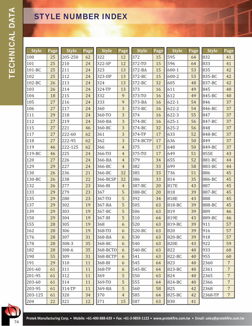
TA STYLE NUMBER INDEX
Style Page100 25101 25101-BC 25102 25102-BC 26103 26104 18105 27106 27111 29112 27115 27117 27118 27119 46119-BC 46120 27129 29130 26130-BC 26132 26133 29135 29137 29139 29150 29155 28162 28176 28178 28182 28190 55191 29201-60 61201-95 61203-60 61203-95 61203-125 61204 22
Style Page205-250 62210 24211 24212 24213 24214 24215 24216 24217 24218 24219 24221 46222-60 62222-95 62222-125 62225 24226 24227 24236 21238 22277 23279 23280 23302 19303 19304 19305 19306 19307 31308-3 35308-6 35309 31310 11311 11312 11314 11314-TP 11320 34321 12
Style Page322 12322-SP 12323 13323-DP 13324 13324-TP 13332 9333 9360 3360-TO 3360-BA 3360-BC 3361 3362 3366 4366-TO 4366-BA 4366-BC 4366-BC 32366-BCSP 32366-BI 4367 5367-TO 5367-BA 5367-BC 5367-BI 5368 6368-TO 6368-BA 6368-BC 6368-BCTO 6368-BCTP 6368-BI 6368-TP 6369 5369-TO 5369-BA 5370 4371 15
Style Page372 15372-TO 15372-BA 15372-BC 15372-BC 32373 16373-TO 16373-BA 16373-BC 16374 16374-BC 16374-BC 32374-TP 17374-BCTP 17375 17375-TO 17379 34382 33385 33386 33387-BC 20388-BC 20392 34505 63506 63510 64520 63520-BC 63530 63540 63540-BC 63541 63545 64545-BC 64550 63555 64560 58585 64587 63
Style Page595 64596 64600-1 53600-2 53605 48611 49612 49622-1 54622-2 54622-3 55625-1 56625-2 56633 52636 50648 50649 51655 52699 58736 51814 35817E 43818 39818E 43818-BC 39819 39819E 43819-BC 39820 39820-BC 39820E 43822 40822-BC 40823 40823-BC 40824 40824-BC 40825 42825-BC 42830 41
Style Page832 41833 41835 42835-BC 42837-BC 42845 40845-BC 40846 37846-BC 37847 37847-BC 37848 37848-BC 37849 37849-BC 37855E 43881-BC 44883-BC 44886 45886-BC 45887 45887-BC 45888 45888-BC 45889 46889-BC 46911 57916 57918 57922 59933 60955 602360 72361 72365 72366 72368 72368-TP 7

LIMITED WARRANTY Protek Manufacturing Corp., 64 Kan Su Road, Section #2, Taichung, Taiwan (“Warrantor”) warrants to the original purchaser of the new fire protection equipment manufactured by Warrantor, and to anyone to whom it is transferred, that the equipment shall be free from defects in material and workmanship during the five (5) year period (electrical components two [2] years) commencing upon the receipt of such equipment by the original purchaser.
Warrantor’s obligation under this warranty is specifically limited to replacing or repairing its equipment or parts which are shown by Warrantor’s examination to be in a defective condition attributable to Warrantor. To qualify for this limited warranty, the claimant must return the equipment to Warrantor, at its above address, transportation charges prepaid, within a reasonable time after discovery of an alleged defect. Warrantor will examine the equipment. If Warrantor determines that there is a defect attributable to it, Warrantor will correct the problem within a reasonable time. If the equipment is covered by this limited warranty, Warrantor will assume the expenses of repair, except for transportation charges and shipping expenses incurred in delivering such equipment to Warrantor.
If any defect attributable to Warrantor under this limited warranty cannot be reasonably cured by repair or replacement, Warrantor may elect to refund the purchase price of the equipment, less reasonable depreciation, in complete discharge of its obligations under this limited warranty. If Warrantor makes this election, the claimant shall return the equipment to Warrantor free and clear of any liens and encumbrances.
This is a limited warranty. The original purchaser of the equipment, any person to whom it is transferred, and any person who is an intended or unintended beneficiary of the equipment, shall not be entitled to recover from Warrantor any consequential or incidental damages for injury to person and/or property resulting from any defective equipment manufactured or assembled by Warrantor.
Warrantor shall have no obligation under this limited warranty if the equipment is, or has been, misused or neglected (including failure to provide reasonable maintenance) or if there have been accidents to the equipment or if it has been repaired or altered by someone else.
THIS IS A LIMITED EXPRESS WARRANTY ONLY. WARRANTOR EXPRESSLY DISCLAIMS WITH RESPECT TO THE EQUIPMENT ALL IMPLIED WARRANTIES OF MERCHANTABILITY AND ALL IMPLIED WARRANTIES OF FITNESS FOR A PARTICULAR PURPOSE. THERE IS NO WARRANTY OF ANY NATURE MADE BY WARRANTOR BEYOND THAT STATED IN THE DOCUMENT.
Warrantor reserves the right to change the parts or design of its products from time to time without notice, and with no obligation to maintain spare parts or to make corresponding changes in the products previously manufactured.
Protek is proud to be ISO 9001:2008 registered with the internationally recognised Underwriter Laboratories Inc. (UL) and CE marking with Bureau Veritas S.A.
WA
RR
AN
TYWARRANTY

0062www.protekfire.com.tw [email protected]
PROTEK MANUFACTURING CORP.
PROTEK MANUFACTURING CORP.
R
CATALOGUE 218