Protection and Detection of Fault in 3-φ, 400kV Line Using · Protection and Detection of Fault in...
5
International Research Journal of Engineering and Technology (IRJET) e-ISSN: 2395 -0056 Volume: 03 Issue: 04 | Apr-2016 www.irjet.net p-ISSN: 2395-0072 © 2016, IRJET | Impact Factor value: 4.45 | ISO 9001:2008 Certified Journal | Page 2173 Protection and Detection of Fault in 3-φ, 400kV Line Using Symmetrical Component Analysis Prashant Gautam 1 , A. K. Jhala 2 , Manish Prajapati 3 1 M. Tech Scholar, Dept of Electrical Engineering, RKDF College of Engineering, Bhopal, MP, India 2 Associate Professor, Dept of Electrical Engineering, RKDF College of Engineering, Bhopal, MP, India 3 Assistant Professor, Dept of Electrical Engineering, RKDF College of Engineering, Bhopal, MP, India ---------------------------------------------------------------------***--------------------------------------------------------------------- Abstract - Protection of power system always been a great area of research for the new researcher and research communities in this context many work has been done for the classification and detection of the fault for the analysis of the system. Three phase transmission line are soul of power system. In this paper different types of fault are classified in the three phase transmission line. In the present scenario the both end ratios are considered for the data acquisition of voltage and currents. These states are measured and fed to the control panel for the fault analysis and detection. These techniques are very much accurate for the short and medium transmission line. But for long transmission line classification needs the accuracy and actual detection of the fault and direction of the fault. For a 400kV, 100MVA, and 112km transmission is simulated and worked in MATLAB/SIMULINK environment Key Words: Transmission Line, Fault Classification, L_G, LLG, LLL faults. Distance Protection 1. INTRODUCTION The performance of any power system network is greatly affected by the transmission line network fault, which raises the disruption in power flow. As to maintain un-interrupted supply and protection for the connected network one need to develop such a technology to achieve the same. Disturbances at power network occurs temporary and permanent basis, occasionally. This fault may be nature caused, climatic effect, equipment failure, aging and human error. The occurrence of fault creates the condition (mostly short circuit), during which heavy current flows through the equipments. Ignorance of this heavy current may burn the system apparatus and affect the continuity of supply. The protection and fault classification has become a challenging job to the present installed system. R. Abouzar et. al. had proposed an extensive study on the sequential component based fault identification for the three phase power transmission line. In his paper positive sequence component and negative sequence component are used to achieve the detection of faults at any position.[1] A. Thompson had proposed method to generalise the fault transmission in power system in accordance with the current sequential components.[2] P. Ray et. al. had given a machine learning based hybrid classification technique for the analysing fault, its detection and classification. In this paper discrete wavelet transformation is used for feature selection of fault and these features are source for the machine learning algorithm. [4] H. Ben et al. proposed a method for detection of faults in Extra High voltage (EVHV) system using artificial neural network (ANN). The type and detection of fault location is done by treatment of voltage and current using ANN.[6] Idea and purpose is to classify and detect fault based on the symmetrical components with their phase angle and magnitude of current. The phasor values of three phase system can be converted into the equivalent symmetrical components. Only, positive and negative components have been used in this paper to perform the classification of faults. In the present scenario, zero sequence components give the definite ground fault but during unbalanced system zero sequence component may present. Although in the un- faulted condition zero sequence may occur in the system. 1.1 Faults and Classification In power system with single circuit line taken as system under study have various type of faults as L-G fault, LL fault, LL-G fault and LLL with and without ground. The grounded faults are more severe as compared to ungrounded fault. Since, grounded faults are more severe because of heavy current flows through the converter and amount of current cannot be limited by any method which further causes the disruption of power system and equipments. In Figure 1 it is clear that the system may observe various type fault as per the occurrences and the severity level. 1.2 Types of Fault Active Fault The fault is called active when actual current flows from one phase conductor to another (phase-to-
Transcript of Protection and Detection of Fault in 3-φ, 400kV Line Using · Protection and Detection of Fault in...
International Research Journal of Engineering and Technology (IRJET) e-ISSN: 2395 -0056
Volume: 03 Issue: 04 | Apr-2016 www.irjet.net p-ISSN: 2395-0072
© 2016, IRJET | Impact Factor value: 4.45 | ISO 9001:2008 Certified Journal | Page 2173
Protection and Detection of Fault in 3-φ, 400kV Line Using
Symmetrical Component Analysis
Prashant Gautam1, A. K. Jhala2, Manish Prajapati3
1 M. Tech Scholar, Dept of Electrical Engineering, RKDF College of Engineering, Bhopal, MP, India 2 Associate Professor, Dept of Electrical Engineering, RKDF College of Engineering, Bhopal, MP, India 3Assistant Professor, Dept of Electrical Engineering, RKDF College of Engineering, Bhopal, MP, India
---------------------------------------------------------------------***---------------------------------------------------------------------
Abstract - Protection of power system always been a great area of research for the new researcher and research communities in this context many work has been done for the classification and detection of the fault for the analysis of the system. Three phase transmission line are soul of power system. In this paper different types of fault are classified in the three phase transmission line. In the present scenario the both end ratios are considered for the data acquisition of voltage and currents. These states are measured and fed to the control panel for the fault analysis and detection. These techniques are very much accurate for the short and medium transmission line. But for long transmission line classification needs the accuracy and actual detection of the fault and direction of the fault. For a 400kV, 100MVA, and 112km transmission is simulated and worked in MATLAB/SIMULINK environment
Key Words: Transmission Line, Fault Classification, L_G,
LLG, LLL faults. Distance Protection
1. INTRODUCTION The performance of any power system network is greatly affected by the transmission line network fault, which raises the disruption in power flow. As to maintain un-interrupted supply and protection for the connected network one need to develop such a technology to achieve the same.
Disturbances at power network occurs temporary and permanent basis, occasionally. This fault may be nature caused, climatic effect, equipment failure, aging and human error. The occurrence of fault creates the condition (mostly short circuit), during which heavy current flows through the equipments. Ignorance of this heavy current may burn the system apparatus and affect the continuity of supply. The protection and fault classification has become a challenging
job to the present installed system.
R. Abouzar et. al. had proposed an extensive study on the sequential component based fault identification for the three phase power transmission line. In his paper positive sequence component and negative sequence component are used to achieve the detection of faults at any position.[1]
A. Thompson had proposed method to generalise the fault transmission in power system in accordance with the current sequential components.[2]
P. Ray et. al. had given a machine learning based hybrid classification technique for the analysing fault, its detection and classification. In this paper discrete wavelet transformation is used for feature selection of fault and these features are source for the machine learning algorithm. [4] H. Ben et al. proposed a method for detection of faults in Extra High voltage (EVHV) system using artificial neural network (ANN). The type and detection of fault location is done by treatment of voltage and current using ANN.[6] Idea and purpose is to classify and detect fault based on the symmetrical components with their phase angle and magnitude of current. The phasor values of three phase system can be converted into the equivalent symmetrical components. Only, positive and negative components have been used in this paper to perform the classification of faults. In the present scenario, zero sequence components give the definite ground fault but during unbalanced system zero sequence component may present. Although in the un-faulted condition zero sequence may occur in the system.
1.1 Faults and Classification
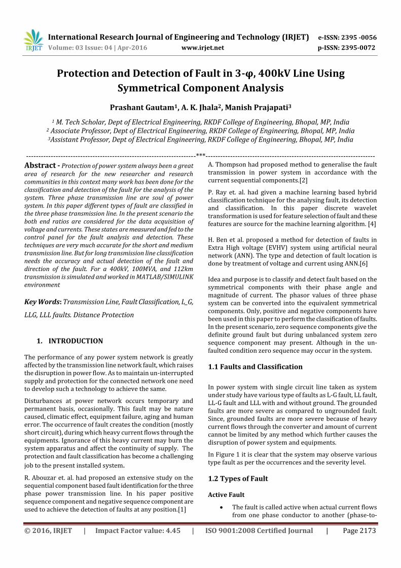
In power system with single circuit line taken as system under study have various type of faults as L-G fault, LL fault, LL-G fault and LLL with and without ground. The grounded faults are more severe as compared to ungrounded fault. Since, grounded faults are more severe because of heavy current flows through the converter and amount of current cannot be limited by any method which further causes the disruption of power system and equipments.
In Figure 1 it is clear that the system may observe various type fault as per the occurrences and the severity level.
1.2 Types of Fault Active Fault
The fault is called active when actual current flows from one phase conductor to another (phase-to-
International Research Journal of Engineering and Technology (IRJET) e-ISSN: 2395 -0056
Volume: 03 Issue: 04 | Apr-2016 www.irjet.net p-ISSN: 2395-0072
© 2016, IRJET | Impact Factor value: 4.45 | ISO 9001:2008 Certified Journal | Page 2174
phase), or alternatively from one phase conductor to earth (phase-to-earth) as commonly popular. This type of fault can also be further classified into two areas, namely the ‘solid’ fault and the ‘incipient’ fault.
Increased damage at fault location. Fault energy = 2=I Rt where t is time in seconds.
Danger to operating personnel (flashes due to high fault energy sustaining for a long time).
Danger of igniting combustible gas in hazardous areas, such as methane in coal mines which could cause horrendous disaster.
Increased probability of earth faults spreading to healthy phases.
Higher mechanical and thermal stressing of all items of plant carrying the fault current, particularly transformers whose windings suffer progressive and cumulative deterioration because of the enormous electromechanical forces caused by multi-phase faults proportional to the square of the fault current.
Sustained voltage dips resulting in motor (and generator) instability leading to extensive shutdown at the plant concerned and possibly other nearby plants connected to the system.
The ‘incipient’ fault, on the other hand, is a fault that starts as a small thing and gets developed into catastrophic failure.
Like for example some partial discharge (excessive discharge activity often referred to as Corona) in a void in the insulation over an extended period can burn away adjacent insulation, eventually spreading further and developing into a ‘solid’ fault.
0
10
20
30
40
50
60
70
80
L-G Fault LL Fault LL-G Fault LLL Fault
Co
mp
aris
ion
of
Fau
lts
Occurance
Severity
Figure 1 Chart showing the Occurrence and Severity of Various Faults
Passive Faults
Reasons behind the active faults are generated by the cumulative actions of passive faults.
Overloading leading to overheating of insulation (deteriorating quality, reduced life and ultimate failure).
Overvoltage: Stressing the insulation beyond its withstand capacities.
Under frequency: Causing plant to behave incorrectly.
Power swings: Generators going out-of-step or out-of-synchronism with each other.
It is therefore very necessary to monitor these conditions to protect the system against these conditions.[6-7]
With the development in power engineering and electrical power apparatus design protection system cannot remain untouched with it.
In the process of development one has seen the performance of electromechanical relay. Due to its high power consumption and slow response in dynamic condition it becomes obsolete for the new installations.
While performance and development in solid state relays replaced the electromechanical relays from the protection time line.
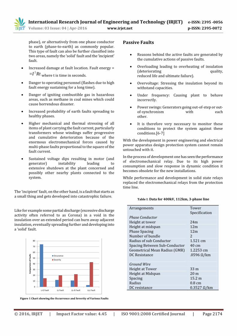
Table I: Data for 400kV, 112km, 3-phase line
Arrangements Tower Specification
Phase Conductor Height at tower 24m Height at midspan 12m Phase Spacing 12m Number of bundle 2 Radius of sub Conductor 1.521 cm Spacing Between Sub-Conductor 40 cm Geometrical Mean Radius (GMR) 1.2253 cm DC Resistance .0596 Ω/km Ground Wire Height at Tower 33 m Height at Midspan 20 m Spacing 15.2 m Radius 0.8 cm DC resistance 0.3527 Ω/km
International Research Journal of Engineering and Technology (IRJET) e-ISSN: 2395 -0056
Volume: 03 Issue: 04 | Apr-2016 www.irjet.net p-ISSN: 2395-0072
© 2016, IRJET | Impact Factor value: 4.45 | ISO 9001:2008 Certified Journal | Page 2175
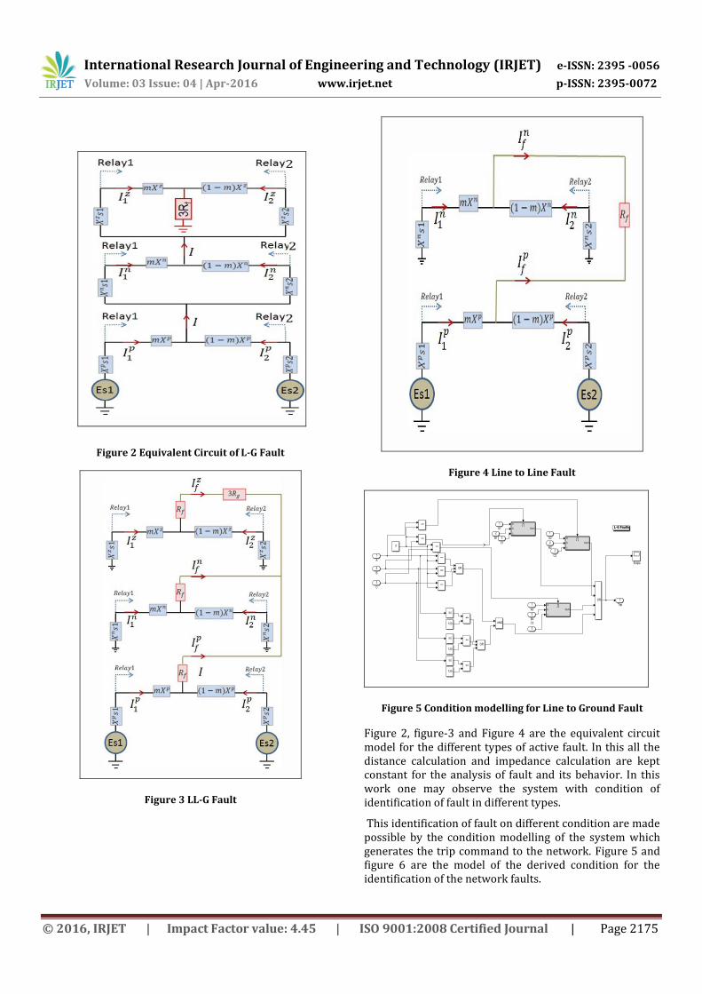
Figure 2 Equivalent Circuit of L-G Fault
Figure 3 LL-G Fault
Figure 4 Line to Line Fault
Figure 5 Condition modelling for Line to Ground Fault
Figure 2, figure-3 and Figure 4 are the equivalent circuit model for the different types of active fault. In this all the distance calculation and impedance calculation are kept constant for the analysis of fault and its behavior. In this work one may observe the system with condition of identification of fault in different types.
This identification of fault on different condition are made possible by the condition modelling of the system which generates the trip command to the network. Figure 5 and figure 6 are the model of the derived condition for the identification of the network faults.
International Research Journal of Engineering and Technology (IRJET) e-ISSN: 2395 -0056
Volume: 03 Issue: 04 | Apr-2016 www.irjet.net p-ISSN: 2395-0072
© 2016, IRJET | Impact Factor value: 4.45 | ISO 9001:2008 Certified Journal | Page 2176
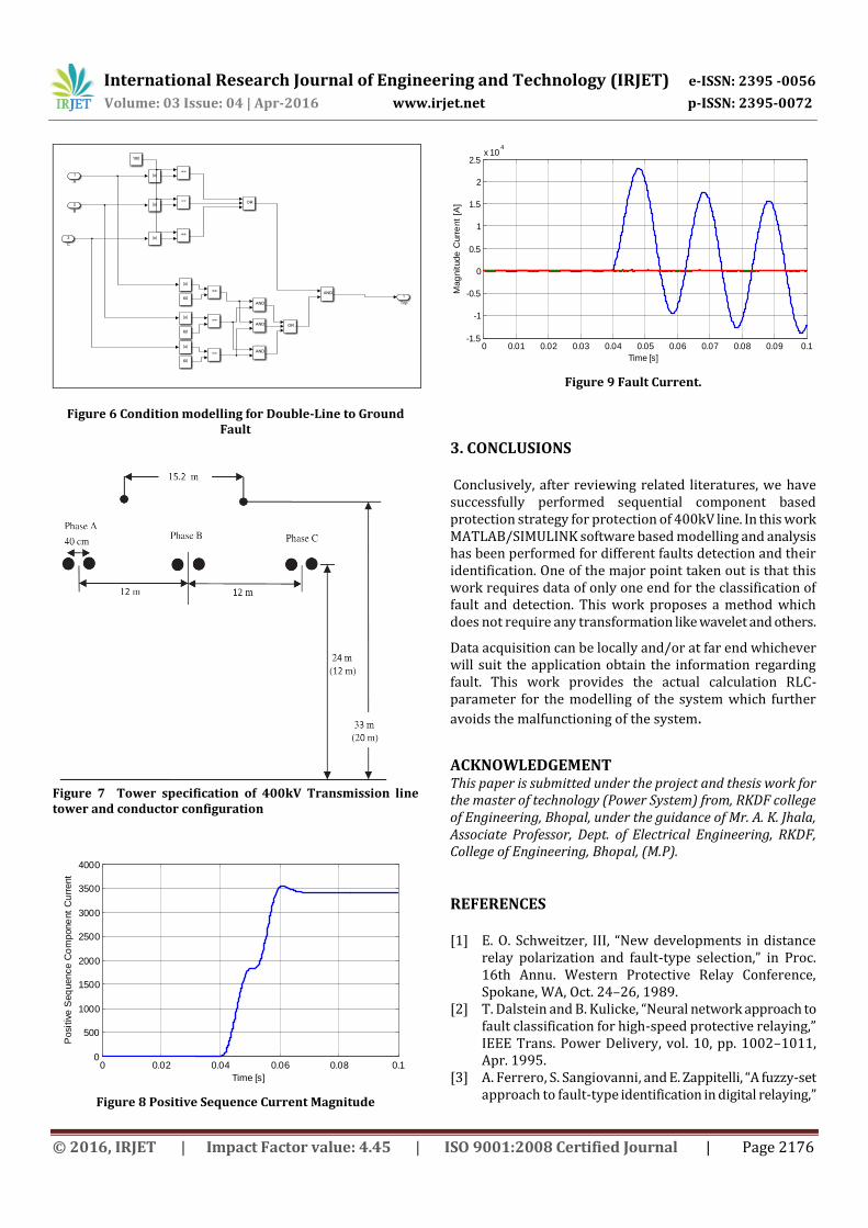
Figure 6 Condition modelling for Double-Line to Ground Fault
Figure 7 Tower specification of 400kV Transmission line tower and conductor configuration
0 0.02 0.04 0.06 0.08 0.10
500
1000
1500
2000
2500
3000
3500
4000
Time [s]
Posi
tive
Seq
uence C
om
pone
nt
Cu
rrent
Figure 8 Positive Sequence Current Magnitude
0 0.01 0.02 0.03 0.04 0.05 0.06 0.07 0.08 0.09 0.1-1.5
-1
-0.5
0
0.5
1
1.5
2
2.5x 10
4
Time [s]
Mag
nitude
Curr
ent
[A]
Figure 9 Fault Current.
3. CONCLUSIONS Conclusively, after reviewing related literatures, we have successfully performed sequential component based protection strategy for protection of 400kV line. In this work MATLAB/SIMULINK software based modelling and analysis has been performed for different faults detection and their identification. One of the major point taken out is that this work requires data of only one end for the classification of fault and detection. This work proposes a method which does not require any transformation like wavelet and others.
Data acquisition can be locally and/or at far end whichever will suit the application obtain the information regarding fault. This work provides the actual calculation RLC-parameter for the modelling of the system which further
avoids the malfunctioning of the system.
ACKNOWLEDGEMENT This paper is submitted under the project and thesis work for the master of technology (Power System) from, RKDF college of Engineering, Bhopal, under the guidance of Mr. A. K. Jhala, Associate Professor, Dept. of Electrical Engineering, RKDF, College of Engineering, Bhopal, (M.P).
REFERENCES [1] E. O. Schweitzer, III, “New developments in distance
relay polarization and fault-type selection,” in Proc. 16th Annu. Western Protective Relay Conference, Spokane, WA, Oct. 24–26, 1989.
[2] T. Dalstein and B. Kulicke, “Neural network approach to fault classification for high-speed protective relaying,” IEEE Trans. Power Delivery, vol. 10, pp. 1002–1011, Apr. 1995.
[3] A. Ferrero, S. Sangiovanni, and E. Zappitelli, “A fuzzy-set approach to fault-type identification in digital relaying,”
International Research Journal of Engineering and Technology (IRJET) e-ISSN: 2395 -0056
Volume: 03 Issue: 04 | Apr-2016 www.irjet.net p-ISSN: 2395-0072
© 2016, IRJET | Impact Factor value: 4.45 | ISO 9001:2008 Certified Journal | Page 2177
IEEE Trans. Power Delivery, vol. 10, pp. 169–175, Jan. 1995.
[4] A. Girgis, “A new Kalman filtering based digital distance relay,” IEEE Transaction on Power Apparatus and System, vol. PAS-101, no. 9, pp. 3471–3480, September 1982.
[5] P. W. Daval and G. Au Yeung, “A software design for computer based impedance relay for transmission line protection,” IEEE Trans. Power App. Syst., vol. PAS-99, pp. 235–244, Jan./Feb. 1980.
[6] T. Adu, “An accurate fault classification technique for power system monitoring devices,” IEEE Trans. Power Del., vol. 17, no. 3, pp. 684–690, Jul. 2002.
[7] Mamiş, Mehmet Salih, Müslüm Arkan, and Cemal Keleş. "Transmission lines fault location using transient signal spectrum." International Journal of Electrical Power & Energy Systems 53 (2013): 714-718.
[8] M. S. Sachdev and M. A. Baribeau, “A new algorithm for digital impedance relays,” IEEE Trans. Power App. Syst., vol. PAS-98, pp. 2232–2240, Nov./Dec. 1979.
[9] M. S. Sachdev and S. R. Kolla, “A polyphase digital distance relay,” in Engineering and Operating Division: Canadian Electrical Assoc., 1987, pp. 1–19.
[10] Shaik, Abdul Gafoor, and Ramana Rao V. Pulipaka. "A new wavelet based fault detection, classification and location in transmission lines." International Journal of Electrical Power & Energy Systems 64 (2015): 35-40.
[11] E. O. Schweitzer, III, “New developments in distance relay polarization and fault-type selection,” in Proc. 16th Annu. Western Protective Relay Conference, Spokane, WA, Oct. 24–26, 1989.
[12] T. Dalstein and B. Kulicke, “Neural network approach to fault classification for high-speed protective relaying,” IEEE Trans. Power Delivery, vol. 10, pp. 1002–1011, Apr. 1995.
[13] A. Ferrero, S. Sangiovanni, and E. Zappitelli, “A fuzzy-set approach to fault-type identification in digital relaying,” IEEE Trans. Power Delivery, vol. 10, pp. 169–175, Jan. 1995.
[14] A. Girgis, “A new Kalman filtering based digital distance relay,” IEEE Transaction on Power Apparatus and System, vol. PAS-101, no. 9, pp. 3471–3480, September 1982.
[15] P. W. Daval and G. Au Yeung, “A software design for computer based impedance relay for transmission line protection,” IEEE Trans. Power App. Syst., vol. PAS-99, pp. 235–244, Jan./Feb. 1980.
[16] T. Adu, “An accurate fault classification technique for power system monitoring devices,” IEEE Trans. Power Del., vol. 17, no. 3, pp. 684–690, Jul. 2002.
[17] Mamiş, Mehmet Salih, Müslüm Arkan, and Cemal Keleş. "Transmission lines fault location using transient signal spectrum." International Journal of Electrical Power & Energy Systems 53 (2013): 714-718.
[18] M. S. Sachdev and M. A. Baribeau, “A new algorithm for digital impedance relays,” IEEE Trans. Power App. Syst., vol. PAS-98, pp. 2232–2240, Nov./Dec. 1979.
[19] M. S. Sachdev and S. R. Kolla, “A polyphase digital distance relay,” in Engineering and Operating Division: Canadian Electrical Assoc., 1987, pp. 1–19.
[20] Blackburn, J. Lewis, Protective Relaying-Principles and Applications, Marcel Dekker Inc., New York and Basel, 1987.
[21] Manitoba HVDC Research Centre, EMTDC User’s Guide, PSCAD version 3.0.8, Manitoba, 2001.
[22] Hugh Hildreth Skilling, Electric Transmission Lines - Distributed Constants, Theory and Applications, McGraw-Hill, New York, 1951.
[23] William H. Hayt Jr., John A. Buck, Engineering Electromagnetics, McGraw-Hill, New York, Sixth Edition, 2001.
[24] L. V. Bewley, Traveling Waves on Transmission Systems, Dover Publications Inc., New York, Second Edition, 1963