
Progress Report to the 5th J-PARC PAC Meeting J-PARC E06 ...research.kek.jp › group › trek ›...
27
Progress Report to the 5th J-PARC PAC Meeting J-PARC E06 (TREK) Experiment Measurement of T-violating Transverse Muon Polarization in K + → π 0 µ + ν µ Decays E06 (TREK) Collaboration ∗ May 28, 2008 ∗ Contact person : J. Imazato ([email protected]) 1
Transcript of Progress Report to the 5th J-PARC PAC Meeting J-PARC E06 ...research.kek.jp › group › trek ›...
Progress Report
to the
5th J-PARC PAC Meeting
J-PARC E06 (TREK) Experiment
Measurement of T-violating Transverse Muon
Polarization in K+ → π0µ+νµ Decays
E06 (TREK) Collaboration∗
May 28, 2008
∗Contact person : J. Imazato ([email protected])
1
Contents
1 Introduction 3
2 Funding efforts 42.1 Grant-in-Aid research support in Japan . . . . . . . . . . . . . . . . . . . . 42.2 Fuding for target R&D in Canada . . . . . . . . . . . . . . . . . . . . . . . 52.3 Funding efforts in U.S.A. for GEM laboratory . . . . . . . . . . . . . . . . . 5
3 Update of theoretical model descriptions of PT 63.1 Importance of PT physics . . . . . . . . . . . . . . . . . . . . . . . . . . . . 63.2 Exotic scalar interactions . . . . . . . . . . . . . . . . . . . . . . . . . . . . 73.3 Multi-Higgs doublet model . . . . . . . . . . . . . . . . . . . . . . . . . . . 83.4 SUSY models . . . . . . . . . . . . . . . . . . . . . . . . . . . . . . . . . . . 10
4 Progress in beamline and optics design 124.1 Design of K1.1 B1 nagnet . . . . . . . . . . . . . . . . . . . . . . . . . . . . 124.2 Comments on the KL beam holes . . . . . . . . . . . . . . . . . . . . . . . . 13
5 Analysis of the CsI(Tl) readout high-rate performance 135.1 APD readout . . . . . . . . . . . . . . . . . . . . . . . . . . . . . . . . . . . 135.2 Analysis of pileup events . . . . . . . . . . . . . . . . . . . . . . . . . . . . . 135.3 Necessity for an improved amplifier . . . . . . . . . . . . . . . . . . . . . . . 17
6 Analysis of the most serious systematic error 176.1 Polarimeter misalignment . . . . . . . . . . . . . . . . . . . . . . . . . . . . 176.2 High statistics MC simulation . . . . . . . . . . . . . . . . . . . . . . . . . . 196.3 Policy for further systematic error studies . . . . . . . . . . . . . . . . . . . 21
7 Plan for this fiscal year 217.1 Polarimeter prototype production and tests . . . . . . . . . . . . . . . . . . 21
7.1.1 Current design of the active polarimeter . . . . . . . . . . . . . . . . 217.1.2 Several-layer prototype . . . . . . . . . . . . . . . . . . . . . . . . . 227.1.3 Full scale prototype . . . . . . . . . . . . . . . . . . . . . . . . . . . 227.1.4 Muon field magnet . . . . . . . . . . . . . . . . . . . . . . . . . . . . 23
7.2 TRIUMF test experiment for MPPC radiation hardness . . . . . . . . . . . 237.3 Target R&D at TRIUMF . . . . . . . . . . . . . . . . . . . . . . . . . . . . 25
8 Status of the TREK collaboration 25
9 Summary 25
2
1 Introduction
In this note we will report on the progress in preparation for the E06 (TREK) experimentsince the last PAC meeting in January 2008. We have proceeded with the detector design,beam optics consideration, systematic error analysis and funding request processes. At thelast meeting we mainly reported the basic R&D of the newly introduced detector elementsby showing their high-rate performance in response to the comments raised by the thirdPAC meeting in July 2007. Based on these achievements and the readiness of the detectordesign, we requested stage-2 approval recommendation from the PAC. These efforts werehighly regarded by the committee; however, the committee provided the following messagein the minutes:
.. Overall the PAC is impressed with the progress of E06 and feels that this is animportant measurement to be made at J-PARC. However, before recommending stage-2approval, the PAC would like to see progress by the TREK collaboration in securing thefunding for the experiment both internationally and domestically and in the collaborativeeffort with the E14 experiment to define and design workable beamlines for both the KL andK1.1 lines.
In this report we will answer these points by showing which kinds of efforts were actuallydone. We can now start the construction of the polarimeter and a part of the active target.Regarding the beamline issue we first had to work out the B1 combined magnet optionof K1.1-BR as proposed in the last PAC since this might affect the whole structure ofthe beamline. The current conclusion will be presented. Several R&D analyses have beencontinued following the preliminary results presented at the last PAC meeting. The newresults of the analysis of the CsI(Tl)-APD readout and the systematic error associated withthe polarimeter misalignment will be reported.
Nearly two years have passed since we submitted the first proposal to the PAC. Thephysics environment around the transverse muon polarization is changing quickly. Wewould like to summarize the model description of PT and its significance among severalother channels with updated data. Finally we would like to present briefly the plan for thecurrent year, for the polarimeter construction, target R&D etc.
Important documents : For reference purposes we summarize here the important doc-uments which we submitted to PAC and FIFC up to now.
• Proposal (April 2006);http://www-ps.kek.jp/imazato/e6/proposal.pdf
• Report to FIFC (June 2007);http://www-ps.kek.jp/imazato/e6/fifc report.pdf
• K0.8 beam optics design report (June 2007);http://www-ps.kek.jp/imazato/e6/k0.8.pdf
• Addendum to K0.8 beam optics design (June 2007);http://www-ps.kek.jp/imazato/e6/k0.8-add.pdf
3
• Report to the third PAC meeting (June 2007);http://www-ps.kek.jp/imazato/e06/PAC3 report.pdf
– Statistical sensitivity estimate (Update of the proposal)– Systematic error analysis– Progress of detector R&D for upgraded elements– Status of collaboration and funding– Conclusion– Appendix: MC simulation of alignment calibration
• Reprot to the forth PAC meeting (December 2007);http://www-ps.kek.jp/imazato/e06/PAC4 report.pdf
– High rate performance of the detector elements– Further study of the K1.1-BR beamline– Funding efforts and international cooperation
2 Funding efforts
In the last 5 months there have been a few positive results of our efforts for TREK exper-iment funding in Japan and in Canada. We are continuing further efforts aiming for fullfunding.
2.1 Grant-in-Aid research support in Japan
The Grand-in-Aid research support money request (Basic Research Category A) for thepolarimeter construction was approved for three Japanese fiscal years 2008-20101 . Withthis money we will prepare 12 sets of polarimeter chambers and a polarimeter magnet.The cashflow is summarized in Table 1. In order to proceed with the construction of the
Table 1: Grant-in-Aid money for the polarimeter constructionYear 2008 2009 2010
Budget (MYen) 9.1 + 2.73 (*) 14.6 13.2(*) = so-called indirect budget to the lab.
other detector elements, and for the preparation and execution of the experiment, we haverecently submitted a request for a five year budget starting from this FY2008 in the newlyestablished category of Grant-in-Aid research support of “New Science Field”, by defininga field of “Search for new physics using slow particle beams at J-PARC” in collaborationwith the neutron group which will look for the neutron EDM and the muon group whichwill look for muonium-antimuonium oscillation. We have requested nearly 1,200 MYen intotal with the fraction of ∼350MYen for the TREK project. The result will be known inlate autumn of this year.
1Unfortunately, the request for Basic Research Category (S) for the whole detector construction exceptfor the target and data-taking electronics was not approved this time.
4
2.2 Fuding for target R&D in Canada
We have been successful in receiving a 3 year project grant from the Natural Sciences andEngineering Research Council (NSERC)–GSC-19 in Canada for the TREK experiment.Funds were requested to construct the fiber target in cooperation with other North Americanuniversities. The amount awarded was 70k$, 130k$, and 120k$ for the fiscal years 2008-9,2009-10, and 2010-11. These amounts will not be sufficient for us to construct the sized fulltarget but they will allow us to pay for travel, hire a graduate student and post-doctoralfellow and also carry out the necessary design studies and test measurements to confirmthe best target fibre readout system – including the preamplifier and phototube system(either single SiPMTs or segmented multi-anode PMTs) with the help of the TRIUMFdetector shop. Professor Hasinoff (UBC) will be at CERN in June and he plans to visitthe FAST group of Professor Pohl at the University of Geneve in order to learn aboutthe detailed studies they have performed before constructing their 1600 channel 4×4× 200mm3 scintillating fibre target for the FAST experiment at PSI – which employs 2 WLSreadout fibres for each 4 × 4 fibre. In addition to the readout tests for the scintillatingfibre system we will also ask the TRIUMF design office to start a mechanical design forthe target support system similar to the one constructed for the E246 target. Now that wehave received NSERC support we can pursue an MOU between TRIUMF and J-PARC forour TREK work here in Canada as recommended by the third PAC meeting.
Table 2: NSERC funding for the target constructionYear 2008-9 2009-10 2010-11
Budget (kCan$) 70 130 120
2.3 Funding efforts in U.S.A. for GEM laboratory
In April 2008 the Hampton University group led by Prof. Michael Kohl submitted a pre-proposal to the US National Science Foundation (NSF) to apply for a so-called IGERT(Integrative Graduate Education and Research Traineeship) grant with the title: “Apply-ing Today’s Technology for Tomorrow’s Science: An Interdisciplinary Program for Develop-ment and Application of GEM Detectors in Nuclear, Particle and Medical Physics”. Uponinvitation by NSF a full proposal will be due in October 2008. This proposal aims to es-tablish a GEM detector lab on campus at Hampton University, to provide the basis forinterdisciplinary research in nuclear, particle and medical physics in multiple specific re-search projects. The GEM-based tracking upgrade of the TREK experiment is one centralapplication of this proposal. The lead institution of this proposal is Hampton University; inaddition, Jefferson Lab, KEK, and MIT are participating institutions who will contributewith their resources and expertise.
The IGERT traineeship program is focused on supporting graduate students from mi-nority universities in interdisciplinary and international research projects and it can alsoprovide the necessary infrastructure of a lab. Hampton University as a Historically BlackCollege and University (HBCU), is particularly suited for such a program. IGERT canprovide funds of up to $600k per year for five years.
5
It is anticipated that additional funds will be required to cover the cost of the specificGEM detectors and electronics for the TREK experiment. In this regard, the group plansto apply separately to NSF within the Nuclear Physics Division for funds to construct theGEM tracking detectors for TREK. Alternatively, an application for a so-called MRI (MajorResearch Instrumentation) grant is currently being discussed.
In parallel, M.K. is working with a graduate student at Hampton University (OzgurAtes) over the summer of 2008 on a baseline design for the TREK C0 and C1 detectorelements. Both the schematic layout as well as a description with the GEANT4 simulationpackage are anticipated by the end of the summer of 2008.
The Hampton University group submitted a funding proposal to NSF in September 2007,to supplement the existing experimental nuclear physics group grant. In that proposal, theenvisioned tracking ugrade of TREK was laid out as a central project. This proposal wasrejected although the panel review reports were very good and the high scientific merit ofTREK was recognized. The main reason for the rejection was the lack of a full approval ofTREK at time of review.
Other universities in the US, University of South Caroline and Iowa State University areeagerly awaiting the stage-2 status before applying for their TREK operating and equipmentfunds from DOE.
3 Update of theoretical model descriptions of PT
3.1 Importance of PT physics
Two years have already passed since the submission of the original E06 (TREK) proposaland the LHC is going to start to run this year. New experimental data to be comparedwith PT in different theoretical models have been improved in several fields and there isalso new theoretical knowledge.
In this section, we would like to update our theoretical description of PT and to confirmonce again the physics impact of PT in the LHC era. In the proposal we did not presentthe model parameter allowed regions in any theoretical model, because we thought it wastoo specific at that moment. In our review of the various theoretical models in this report,we will show some important model constraint figures.
There has been a series of workshops “Flavor Physics in the LHC Era”[1] held at CERNin 2006 with the final summary meeting in March 2007. In the working groups of “lepton”and “K- and D-mesons” the PT physics was one of the topics with its ability to find newphysics together with other T-odd quantities revealing CP violation beyond the StandardModel. In particular the unique feature to probe the Higgs dynamics with charged Higgsexchange in PT was emphasized, which is otherwise accessible only in future high precisonB-decay experiments[2]. At the moment PT is thought to be insensitive to the MinimalSupersymmetry Standard Model (MSSM) with two Higgs doublets. Therefore, it cannot bedenied that the outcome of LHC in a few years after the start has some significant meaningto PT physics. On the other hand, it is also argued that there should be no a prioriconstraints on the structure of the Higgs sector and the number of its doublets. We believeit is very meaningful to pursue the study of Higgs dynamics even after SUSY particles arefound; a few variants of SUSY may also produce a sizable PT as discussed below. In thecase where SUSY is not confirmed soon, the importance of new physics searches such as
6
PT will become much larger. Apart from the CP violation models also, the violation of oneof the fundamental discrete symmetries such as “time reversal invariance” should have aconsiderable impact on our understanding of nature.
3.2 Exotic scalar interactions
In the presence of the predominant T-conserving in-plane polarization, a small transversecomponent of PT is described in terms of a physics parameter Imξ after factoring out thekinematical factor as
PT = Imξ · mµ
mK
|�pµ|[Eµ + |�pµ|�nµ · �nν − m2
µ/mK ]. (1)
The quantity Imξ is non-zero when T is violated and this quantity is what we will measurewith high precision. This kinematical factor shows the advantage for Kµ3 over Ke3. Forthe full detector acceptance there is an approximate relation of < PT >∼ 0.3Imξ. We canwrite down the Lagrangian of a generic four fermion interaction with the coefficients forexotic interaction of scalar (GS), pseudo-scalar (GP ), vector (GV ), and axial vector (GA)neglecting the tensor contribution as
L = − GF√2
sin θC sγα(1 − γ5)u νγα(1 − γ5)µ
+ GS su ν(1 + γ5)µ + GP sγ5u ν(1 + γ5)µ+ GV sγαu νγα(1 − γ5)µ + GA sγαγ5u νγα(1 − γ5)µ + h.c. , (2)
Imξ can be expressed with the imaginary part of the scalar coupling coefficent GS as
Imξ =(m2
K − m2π)ImG∗
S√2(ms − mu)mµGF sin θC
(3)
where ms and mu are the masses of the s-quark and u-quark, respectively. Thus, PT isinduced by exotic scalar interactions such as the charged Higgs exchange. The situationis different if we look at the similar transverse muon polarization PT in the radiative kaondecay of K+ → µνγ which is caused by pseudo-scalar interaction GP [3]. The most stringentlimit to Imξ has been given by our previous E246 experiment to be |ImGS |/GF < 2.2×10⁻⁴
and this will be improved to 1 × 10⁻⁵ in the TREK experiment.Chang and Ng[4] analyzed PT in terms of an effective field theory using an effective
Lagrangian as the sum of the Standard Model term and non-renormalizable ones resultingfrom integrating out the unknown degrees of freedom of new physics above a cut-off scaleΛ. Our PT physics is relevant to the dimension 6 operator in the expansion of Leff =LSM +L5/Λ′ +L6/Λ2 + · · ·. The charged current terms at the electroweak scale in the masseigen-basis are
−LCC6 = C ′
V2(uiγµLdi)(eiγµLνi) + Cij.kl
S1(uiRdj)(ekLνl)
− Cij.klS2
(diRuj)(νkRel) − Cij,klT (diσµνRuj)(νkσµνRel) + h.c. (4)
where CV , CS , and CT are the Wilson coefficients for the vector, scalar and tensor terms,respectively. The imaginary part of CS (as well as CT ) gives rise to CP violation. The E246result yielded
|ImCKS | ≤ 2 × 10⁻³(Λ/TeV)2. (5)
7
This will be further improved to 1 × 10⁻⁴(Λ/TeV)2 in the TREK experiment. In thefollowing we will discuss a few scalar interaction models which may produce a sizeable PT
value, and which were mentioned in the proposal.
3.3 Multi-Higgs doublet model
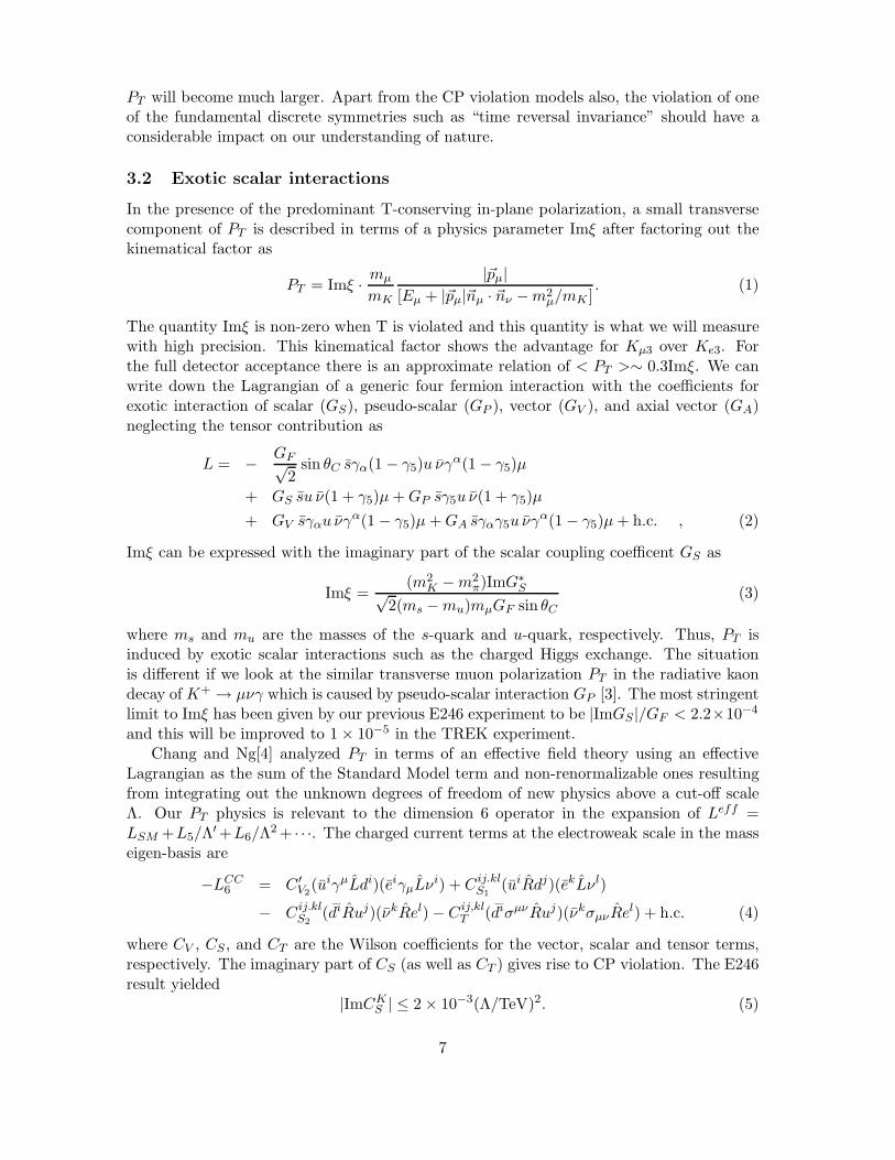
One of the most distinct features of PT is its high sensitivity to charged Higgs exchange attree level. In the two-Higgs doublet model as well as in MSSM, however, no CP violationappears in the Higgs sector due to Natural Flavor Conservation (NFC). Only a small effectcan be produced by loop-induced coupling (in SUSY) such as the loop-induced FlavorChanging Neutral Current (FCNC). Three Higgs doublet models (3HDM), on the otherhand, may give rise to a large effect under the NFC condition with the interference of theHiggs exchange with the SM W boson exchange (Fig.1). New CP violating phases can beintroduced in the charged Higgs mass matrix if the number of doublets is more than twoin models without tree-level FCNCs. Historically a number of papers have applied thesemodels to PT as the most promising candidate theory. The coupling of quarks and leptonsto the Higgs boson is expressed in terms of the Lagrangian
L = (2√
2GF )12
2∑i=1
{αiuLV MDdRH+i + βiuRMUV dLH+
i + γiνLMEeRH+i } + h.c., (6)
where αi, βi, and γi are the quark and lepton couplings to the lightest charged Higgs boson,
Figure 1: PT appears as the interference of the charged Higgs boson exchange with thestandard model W boson exchange.
respecively, and CP can be broken if αi, βi and/or γi have complex phases. Imξ is expressedas
Imξ =m2
K
m2H
Im(γ1α∗1), (7)
thus, constraining the model parameter Im(γ1α∗1). As was discussed in the proposal, several
other channels (e.g. B-meson leptonic B → τν and semi-leptonic B → Xτν decay, B-mesonradiative decay b → sγ, the d quark contribution to the neutron electric dipole moment(EDM) are also sensitive to this quantity. The neutron EDM and b → sγ are related to theother parameter Im(α1β
∗1) of only with quark couplings directly, but these two parameters
are connected by the relationship Im(α1β∗1) = −(v3/v2)2Im(γ1α
∗1) using the Higgs field
vacuum expectation values of v3 and v2. The most recent data for the neutron EDM isdn = 3 × 10⁻²⁶e cm[5]. Recent data for B → Xτν and b → sγ, come from OPAL and
8
102
103
104
0 20 40 60 80 100 120
Im (γ
1 α1* )
(e)(e)(c)
(d)
(a)
(b)
v / v2 3
TREK goal
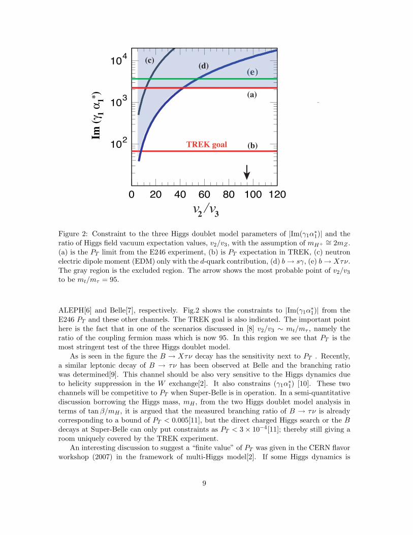
Figure 2: Constraint to the three Higgs doublet model parameters of |Im(γ1α∗1)| and the
ratio of Higgs field vacuum expectation values, v2/v3, with the assumption of mH+∼= 2mZ .
(a) is the PT limit from the E246 experiment, (b) is PT expectation in TREK, (c) neutronelectric dipole moment (EDM) only with the d-quark contribution, (d) b → sγ, (e) b → Xτν.The gray region is the excluded region. The arrow shows the most probable point of v2/v3
to be mt/mτ = 95.
ALEPH[6] and Belle[7], respectively. Fig.2 shows the constraints to |Im(γ1α∗1)| from the
E246 PT and these other channels. The TREK goal is also indicated. The important pointhere is the fact that in one of the scenarios discussed in [8] v2/v3 ∼ mt/mτ , namely theratio of the coupling fermion mass which is now 95. In this region we see that PT is themost stringent test of the three Higgs doublet model.
As is seen in the figure the B → Xτν decay has the sensitivity next to PT . Recently,a similar leptonic decay of B → τν has been observed at Belle and the branching ratiowas determined[9]. This channel should be also very sensitive to the Higgs dynamics dueto helicity suppression in the W exchange[2]. It also constrains (γ1α
∗1) [10]. These two
channels will be competitive to PT when Super-Belle is in operation. In a semi-quantitativediscussion borrowing the Higgs mass, mH , from the two Higgs doublet model analysis interms of tan β/mH , it is argued that the measured branching ratio of B → τν is alreadycorresponding to a bound of PT < 0.005[11], but the direct charged Higgs search or the Bdecays at Super-Belle can only put constraints as PT < 3 × 10⁻⁴[11]; thereby still giving aroom uniquely covered by the TREK experiment.
An interesting discussion to suggest a “finite value” of PT was given in the CERN flavorworkshop (2007) in the framework of multi-Higgs model[2]. If some Higgs dynamics is
9
responsible for the discovered direct CP violation in the K0 system which is described byRe(ε′/ε) = (1.66 ± 0.26) × 10−3, this effect can be converted to PT . This Re(ε′/ε) value isequivalent to decay rate difference between K0 → f and K0 → f of 5×10⁻⁶[12]. Since the∆I = 1/2 transition is dominant in the K0 → 2π system, it should be suppressed. In thecharged K+ system of PT , however, there should be no such suppression. Assuming the∆I = 1/2 suppression factor to be 20, we calculate a CP violation effect in the charged K+
to be ∼ 5×10−6×20 ∼ 10−4 without enhanced couplings to leptons due to v2/v3 mentionedabove. Regarding the origin of ε′/ε, there seems to be no conclusion yet. Therefore, thiskind of qualitative discussion is a strong motivation for a PT search with a sensitivity of10−4.
3.4 SUSY models
Although the Minimal Supersymmetric Standard Model (MSSM) predicts only unobserv-ably small PT [13] without tuning of relevant flavor parameters, the SUSY with R-parityviolation[14] or SUSY with large squark mixing[15] can also give rise to a sizeable value ofPT as was in the proposal. If R-parity violation is allowed a superpotential is defined[16]as W = WMSSM + WRPV with
WRPV = λijkLiLjEk + λ′ijkLiQjDk + λ′′
ijkUiDjDk (8)
where i, j = 1, 2, 3 are generation indices with a summation implied. Li(Qi) are the lepton(quark) doublet superfields and Ej(Dj , Uj) are the electron (down- and up-quark) singletsuperfield. λ,λ′ and λ′′ are the Yukawa couplings; the former two relevant to lepton numberviolation and the latter relevant to baryon number violation. There are altogether 48independent λijk’s which should be determined experimentally.
Our PT can be expressed in this formalism as a sum of two components of sleptonexchange and down-type squark exchange as Imξ = Imξ l + Imξd with
Imξ l =∑
i
Im[λ2i2(λ′i12)
∗]4√
2GF sin θc(mli)2
· m2K
mµms(9)
Imξd =∑
i
Im[λ′21k(λ′
22k)∗]
4√
2GF sin θc(mdk)2
· m2K
mµms. (10)
Thus, we constrain Im[λ2i2(λ′i12)
∗]/m2li
and Im[λ′21k(λ
′22k)∗]/m2
dk(sumation is implied). The
limit of these summations (assuming a common mass scale for mliand mdk
) is plotted as afunction of the mass scale for the E246 PT limit and the TREK goal.
There are a number of experimental and theoretical efforts to analyze λ,λ′ and λ′′ inother channels. In a recent paper[17] and review papers[18, 19] currently updated limitsare compiled also for the products λλ′, λ′λ′, etc. There are 6 relevant parameters for PT
as shown in Eq.10 which are summarized in Table 3. Regarding the 3 paraneters for thedown-type squark exchange, a recent analysis of the K+ → π+νν sets the most stringentlimit of |λ′∗
i2nλ′i1n/m2
dnL| ≤ 2.8 × 10⁻⁵[20]. As for one of the slepton exchange terms, only
the |λ∗232λ
′312| term is constrained to be < 3.8 × 10⁻⁷m2[19], and the other two termes
are not constrained in any other experiments. The limits of these constrained from otherexperiments are also shown in Fig.3 as the absolute value (not imaginary part) of the
10
10-6
10-5
10-4
10-3
10-2
0 100 200
(a)
(b)
(c)(d)
m~
[GeV]
Im(λ
λ* ) [G
eV ]2
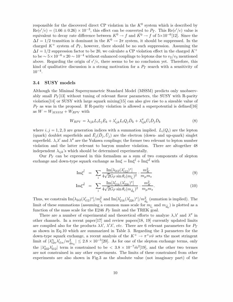
Figure 3: The constraint on ΣIm(λλ′) and ΣIm(λ′λ′) in Eq.10 are plotted for the E246 result(a) and the TREK expectation (b). The limits for the individual parameters in absolutevalue from other experiments are also shown; (c) for |λ∗
232λ′312| from KL → µ+µ−[20], and
(d) |λ′∗22kλ
′21k| from K+ → π+νν[19].
Table 3: The R-pariry violating SUSY parameters relevant to PT and the constraints fromother experiments.
Paraneter Upper bound Experiment|λ∗
232λ′312| 3.8 × 10⁻⁶m2 KL → µ+µ−[19]
Imξ l |λ∗212λ
′112| no constraint
|λ∗222λ
′212| no constraint
|λ′∗211λ
′221| 2.8 × 10⁻⁵m2 K+ → π+νν[20]
Imξd |λ′∗212λ
′222| 2.8 × 10⁻⁵m2 K+ → π+νν[20]
|λ′∗213λ
′223| 2.8 × 10⁻⁵m2 K+ → π+νν[20]
11
individual parameters. It can be see that PT constrains the relevant parameters moststringently.
For the SUSY model with large squark mixing[15] there is nothing to update since theproposal.
4 Progress in beamline and optics design
4.1 Design of K1.1 B1 nagnet
In the report to the last PAC meeting we discussed the necessity to recover the acceptanceof the K1.1(-BR) beamline which was decreased for this channel by the presence of thepreceding K1.8 beamline. Based on a beam optics calculation we proposed to constructthe beamline with a combined-function magnet in place of the first bending magnet B1.The combined function magnet would have been realized by creating an n-value for B1 asB(x) = B0(1−nx/ρ). In this optics calculation the best case was obtained with n = −6.75while keeping the configuration of the other elements unchanged.
Since the introduction of a non-uniform gap may cause some technical problems, weinvestigated the feasibility of this kind of magnet by doing 2D magnetic field calculations.Because the component construction around the T1 target is now well advanced, and alsobecause the original plan for K1.1-BR is the common use for K1.1 operation, it turnedout that the realization of a combined-function magnet with large n-value would be verydifficult. The reasons are the following:
• The non-flat gap of the magnet causes magnetization saturation at the narrow gappart. The effect is too significant already at the excitation of 0.8 GeV/c to secure asufficiently constant field gradient dBy/dx. The only way to avoid this situation is tolower the central dipolar field by extending the magnet length. However, the currentmagnet length is strictly constrained by the existing vacuum vessel and the beam lineaxis after the bending. A length of more than the 80 cm of the current design isimpossible.
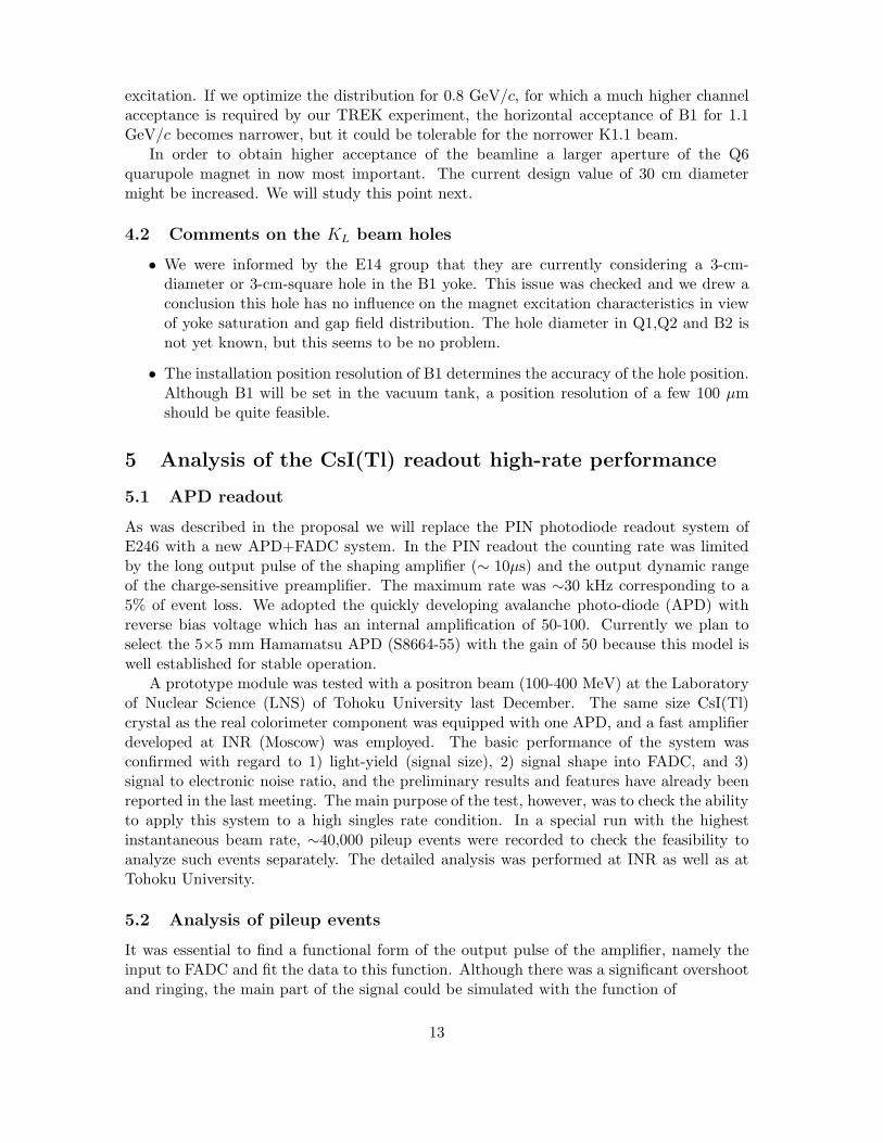
• Even for a smaller n-value the ratio of the dipole and quadrupole field is excitationdependent. It is also difficult to achieve a constant field gradient for the two differentexcitations of 0.8 GeV/c and 1.1 GeV/c. Fig.4 shows the field distribution at n =−2.5 for the excitation for 0.8 GeV/c and 1.1 GeV/c. This means that it is veryunrealistic that one can construct a beamline with an optimal beam optics for bothbeam momenta.
Therefore, we may have to give up the very attractive idea of the combined magnet for B1,which could have increased the acceptance by 75%.
In the course of this study we found that the horizontal acceptance of the first bendB1 is also essential to obtain the highest channel acceptance in addition to the aparture ofQ6. The currently fixed geometry in the vacuum vessel and the conflict with the K1.8 B1magnet seems to constrain the actual pole width of K1.1 B1 to 26 cm. However, our beamoptics calculation was based on the assumption of ±10 cm acceptance. A calculation wasperformed to find the best B1 field distribution and we discovered that a sufficiently flatfield distribution over the ±10 cm can be obtained only an arrangement of shims at thepole edges. Fig.5 show the calculated field distributions for both 0.8 GeV/c and 1.1 GeV/c
12
excitation. If we optimize the distribution for 0.8 GeV/c, for which a much higher channelacceptance is required by our TREK experiment, the horizontal acceptance of B1 for 1.1GeV/c becomes narrower, but it could be tolerable for the norrower K1.1 beam.
In order to obtain higher acceptance of the beamline a larger aperture of the Q6quarupole magnet in now most important. The current design value of 30 cm diametermight be increased. We will study this point next.
4.2 Comments on the KL beam holes
• We were informed by the E14 group that they are currently considering a 3-cm-diameter or 3-cm-square hole in the B1 yoke. This issue was checked and we drew aconclusion this hole has no influence on the magnet excitation characteristics in viewof yoke saturation and gap field distribution. The hole diameter in Q1,Q2 and B2 isnot yet known, but this seems to be no problem.
• The installation position resolution of B1 determines the accuracy of the hole position.Although B1 will be set in the vacuum tank, a position resolution of a few 100 µmshould be quite feasible.
5 Analysis of the CsI(Tl) readout high-rate performance
5.1 APD readout
As was described in the proposal we will replace the PIN photodiode readout system ofE246 with a new APD+FADC system. In the PIN readout the counting rate was limitedby the long output pulse of the shaping amplifier (∼ 10µs) and the output dynamic rangeof the charge-sensitive preamplifier. The maximum rate was ∼30 kHz corresponding to a5% of event loss. We adopted the quickly developing avalanche photo-diode (APD) withreverse bias voltage which has an internal amplification of 50-100. Currently we plan toselect the 5×5 mm Hamamatsu APD (S8664-55) with the gain of 50 because this model iswell established for stable operation.
A prototype module was tested with a positron beam (100-400 MeV) at the Laboratoryof Nuclear Science (LNS) of Tohoku University last December. The same size CsI(Tl)crystal as the real colorimeter component was equipped with one APD, and a fast amplifierdeveloped at INR (Moscow) was employed. The basic performance of the system wasconfirmed with regard to 1) light-yield (signal size), 2) signal shape into FADC, and 3)signal to electronic noise ratio, and the preliminary results and features have already beenreported in the last meeting. The main purpose of the test, however, was to check the abilityto apply this system to a high singles rate condition. In a special run with the highestinstantaneous beam rate, ∼40,000 pileup events were recorded to check the feasibility toanalyze such events separately. The detailed analysis was performed at INR as well as atTohoku University.
5.2 Analysis of pileup events
It was essential to find a functional form of the output pulse of the amplifier, namely theinput to FADC and fit the data to this function. Although there was a significant overshootand ringing, the main part of the signal could be simulated with the function of
13
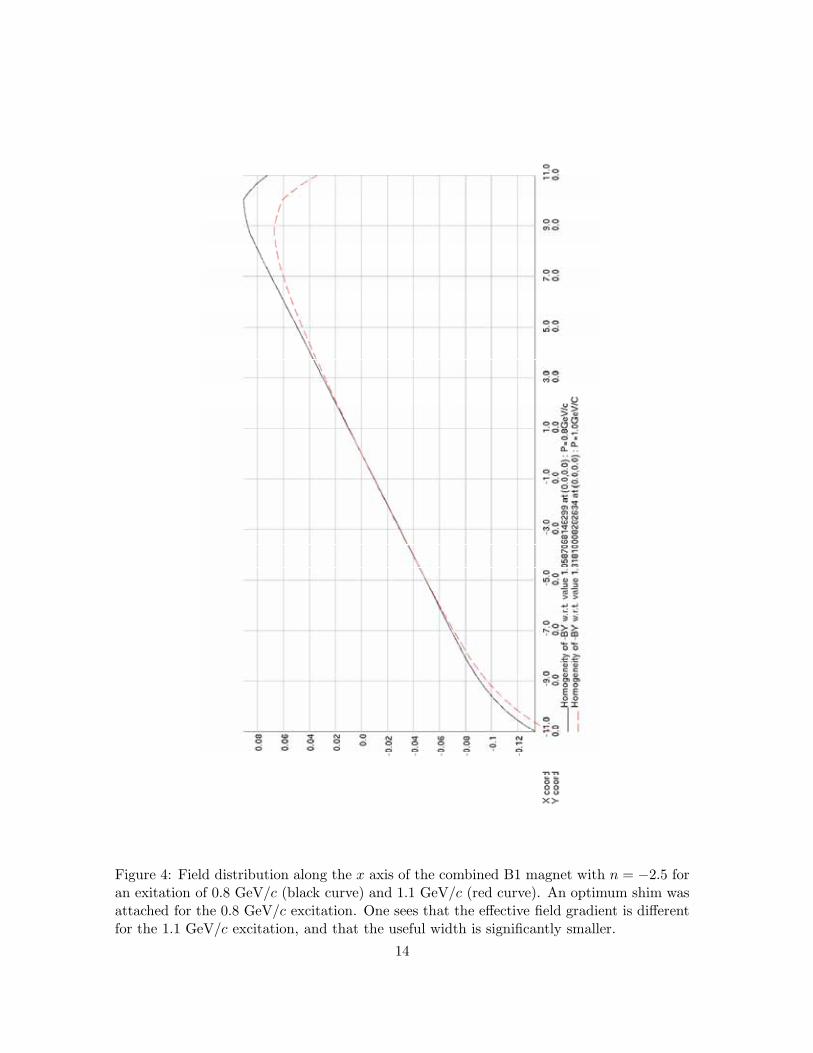
Figure 4: Field distribution along the x axis of the combined B1 magnet with n = −2.5 foran exitation of 0.8 GeV/c (black curve) and 1.1 GeV/c (red curve). An optimum shim wasattached for the 0.8 GeV/c excitation. One sees that the effective field gradient is differentfor the 1.1 GeV/c excitation, and that the useful width is significantly smaller.
14
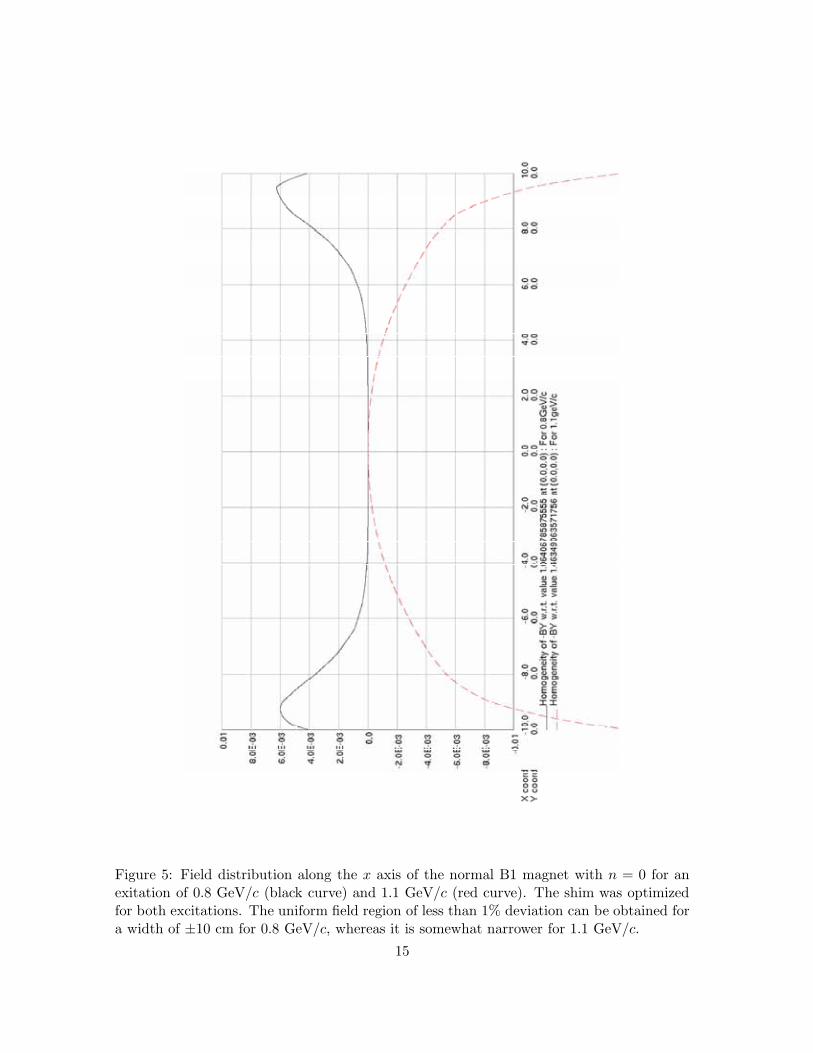
Figure 5: Field distribution along the x axis of the normal B1 magnet with n = 0 for anexitation of 0.8 GeV/c (black curve) and 1.1 GeV/c (red curve). The shim was optimizedfor both excitations. The uniform field region of less than 1% deviation can be obtained fora width of ±10 cm for 0.8 GeV/c, whereas it is somewhat narrower for 1.1 GeV/c.
15
0
FADC bin
FA
DC
am
plitu
de
Figure 6: Signal shape of the amplifier output pulse and its fit to the function of Eq.11
F (x) = p0 − p1ep2x{p3 × Erf(p4x − p5) + p6} (11)
Erf(x) =2√π
∫ x
0e−t2dt . (12)
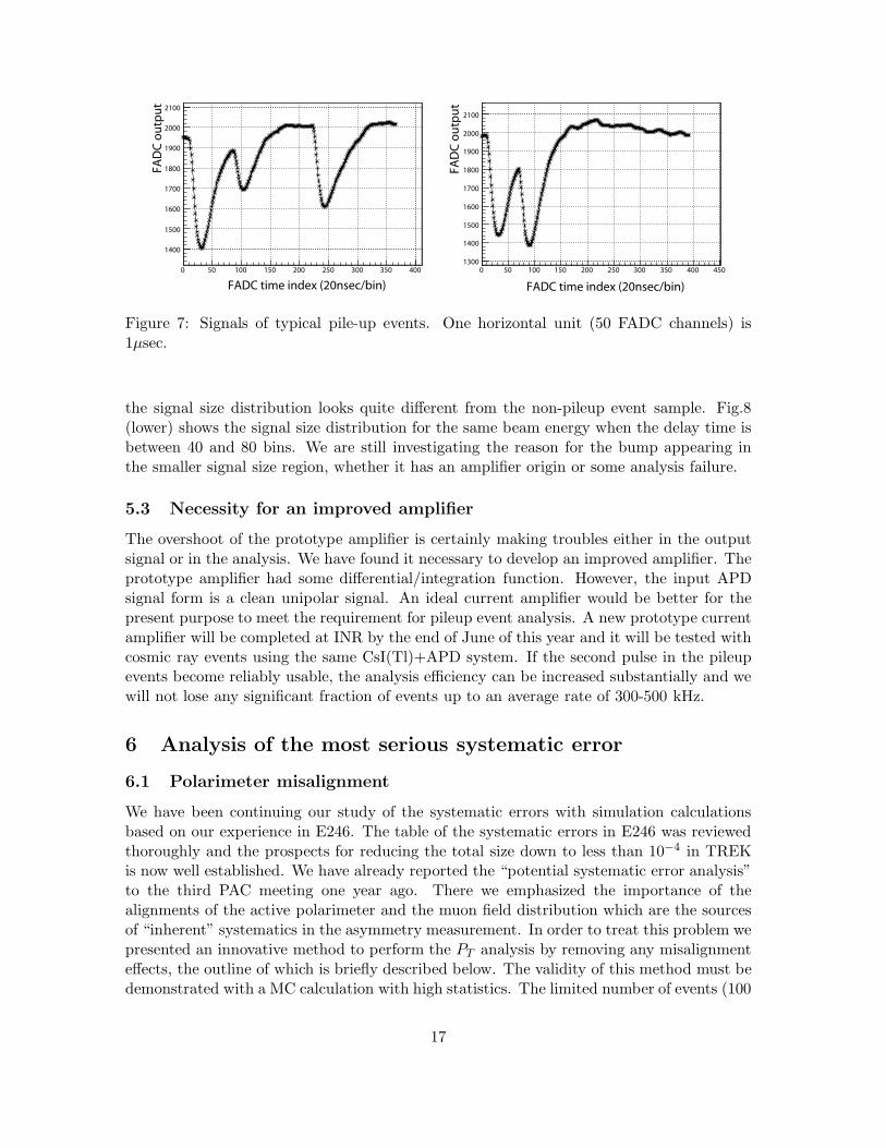
A typical fit for a beam energy of 400 MeV is shown in Fig.6 demonstrating fairly goodagreement in the signal region. Pileup events for a certain beam energy (typical signalshape is shown in Fig.7 with a pulse width of ∼ 1.5µs ) were fitted to a superpositionof the two fit functions and the signal size defined as the integration of the function wascompared with the non-pileup single events. Fig.8 (upper) shows the signal size distributionfor non-pileup events and Fig.8 (middle) shows the signal size distribution of the first pulsein the pileup events for the beam energy of 400 MeV. Good agreement can be seen in boththe distribution form and in the peak position. The analysis efficiency as a function oftime difference of the second pulse in the pileup events has almost flat distribution of 100%above bin 40. From these results we may conclude that if the real triggered signal is thefirst pulse, then events can be saved as long as the pulse separation is larger than ∼ 0.8µscorresponding to 40 bins in Fig.6 and 7 as long as the second pulse is high enough. A moredetailed analysis is currently underway concerning the separability of a pileup event withdifferent height and the the analysis efficiency as the function of the separation. Regardingthe pileup events with almost overlapping pulses, these can be rejected in the fit by thepulse width.
For the second pulse analysis, however, the situation is more complicated due to thepresence of the overshoot and the ringing in the amplifier output. Even if the effect of theovershoot is taken into account by knowing its signal size ratio to the main negative part,
16
FADC time index (20nsec/bin)0 50 100 150 200 250 300 350 400
FAD
C ou
tput
1400
1500
1600
1700
1800
1900
2000
2100
FADC time index (20nsec/bin)0 50 100 150 200 250 300 350 400 450
FAD
C ou
tput
1300
1400
1500
1600
1700
1800
1900
2000
2100
Figure 7: Signals of typical pile-up events. One horizontal unit (50 FADC channels) is1µsec.
the signal size distribution looks quite different from the non-pileup event sample. Fig.8(lower) shows the signal size distribution for the same beam energy when the delay time isbetween 40 and 80 bins. We are still investigating the reason for the bump appearing inthe smaller signal size region, whether it has an amplifier origin or some analysis failure.
5.3 Necessity for an improved amplifier
The overshoot of the prototype amplifier is certainly making troubles either in the outputsignal or in the analysis. We have found it necessary to develop an improved amplifier. Theprototype amplifier had some differential/integration function. However, the input APDsignal form is a clean unipolar signal. An ideal current amplifier would be better for thepresent purpose to meet the requirement for pileup event analysis. A new prototype currentamplifier will be completed at INR by the end of June of this year and it will be tested withcosmic ray events using the same CsI(Tl)+APD system. If the second pulse in the pileupevents become reliably usable, the analysis efficiency can be increased substantially and wewill not lose any significant fraction of events up to an average rate of 300-500 kHz.
6 Analysis of the most serious systematic error
6.1 Polarimeter misalignment
We have been continuing our study of the systematic errors with simulation calculationsbased on our experience in E246. The table of the systematic errors in E246 was reviewedthoroughly and the prospects for reducing the total size down to less than 10−4 in TREKis now well established. We have already reported the “potential systematic error analysis”to the third PAC meeting one year ago. There we emphasized the importance of thealignments of the active polarimeter and the muon field distribution which are the sourcesof “inherent” systematics in the asymmetry measurement. In order to treat this problem wepresented an innovative method to perform the PT analysis by removing any misalignmenteffects, the outline of which is briefly described below. The validity of this method must bedemonstrated with a MC calculation with high statistics. The limited number of events (100
17
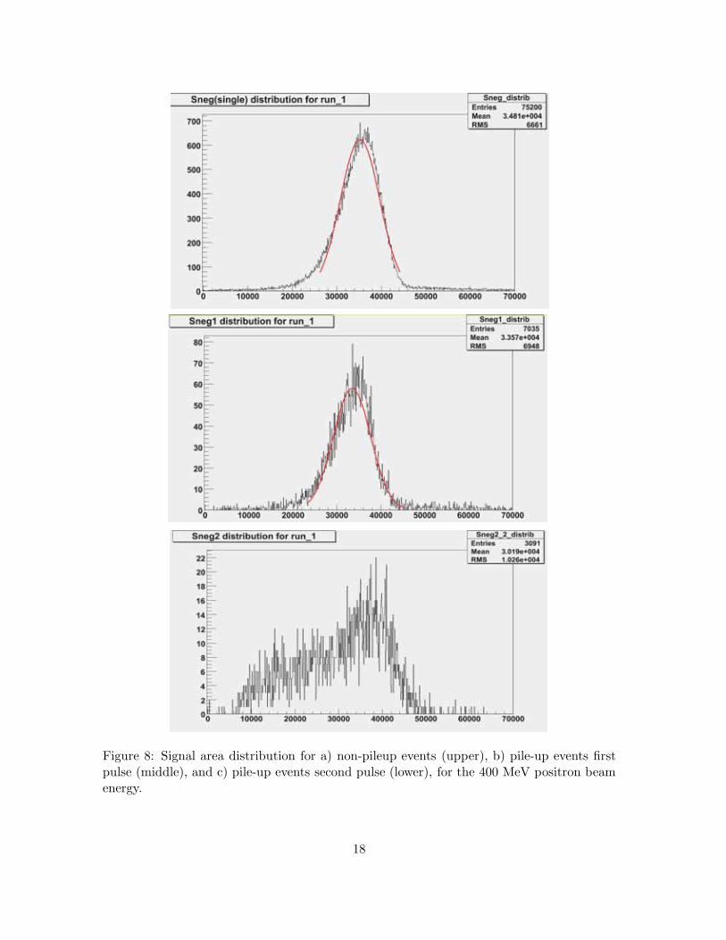
Figure 8: Signal area distribution for a) non-pileup events (upper), b) pile-up events firstpulse (middle), and c) pile-up events second pulse (lower), for the 400 MeV positron beamenergy.
18
million) in that study, however, resulted in the accuracy of ∆PT = (2± 7)× 10−4, althoughthe assumption was for an exaggerated field rotation of 5◦. The necessity to improve thisanalysis statistically was also pointed out in the PAC meeting.
Here we report on the new results of Monte Carlo studies with much higher statistics of∼25 billion Kµ3 events which should correspond to ∆P av
sub < 10−4. In this simulation morerealistic misalignments with 10mrad field rotations were assumed. On the other hand, theMonte Carlo code and the analysis procedure were the same as the previous studies.
6.2 High statistics MC simulation
Now we describe the result briefly along with the principle of the method. As in E246 themisalignments of the polarimeter detector and the muon holding field distribution remainthe most serious systematic which cannot be cancelled out either in the 12-fold rotationalsummation or in the π0 forward (fwd) and π0 backward (bwd) subtraction. The timeintegrated e+ left/right asymmetry due to the misalignments can be described for arbitraryinitial muon spin phase in the median planes θ0 measured from the direction of z bean axisas,
A(θ0) = α0[δrcosθ0 − δzsinθ0 + η(θ0)], (13)
where δz and δr correspond to the muon field rotation for the z(beam) and r(radial) direc-tions, respectively. α0 is the analyzing power for the polarization determination from thee+ asymmetry. The oscillation terms are drastically reduced by the time integration andthe contribution due to imperfect cancellation of the oscillation terms is expressed as η(θ0).It is noted that the misalignments of the polarimeter itself were integrated out into η(θ0)and hence they are not relevant in the further discussion.
In order to extract the misalignment parameters δr and δz in the presence of a realPT signal, we calculate two asymmetries Asum and Asub as a function of θ0, i.e., the sumand difference of Afwd and Abwd – the asymmetries at the forward and backward pions,respectively. This leads to
Asum(θ0) = [Afwd(θ0) + Abwd(θ0)]/2 = α0[δrcosθ0 − δzsinθ0 + η(θ0)] (14)Asub(θ0) = [Afwd(θ0) − Abwd(θ0)]/2 = F (PT , θ0). (15)
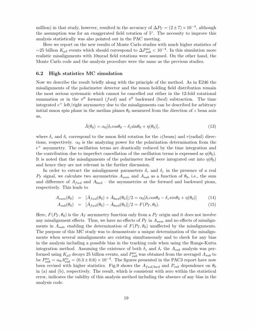
Here, F (PT , θ0) is the AT asymmetry function only from a PT origin and it does not involveany misalignment effects. Thus, we have no effects of PT in Asum and no effects of misalign-ments in Asub, enabling the determination of F (PT , θ0) unaffected by the misalignments.The purpose of this MC study was to demonstrate a unique determination of the misalign-ments when several misalignments are existing simultaneously and to check for any biasin the analysis including a possible bias in the tracking code when using the Runge-Kuttaintegration method. Assuming the existence of both δz and δr the Asub analysis was per-formed using Kµ3 decays 25 billion events, and P av
sub was obtained from the averaged Asub tobe P av
sub = α0Aavsub = (0.3± 0.6)× 10−4. The figures presented in the PAC3 report have now
been revised with higher statistics. Fig.9 shows the Afwd/bwd and Psub dependence on θ0
in (a) and (b), respectively. The result, which is consistent with zero within the statisticalerror, indicates the validity of this analysis method including the absence of any bias in theanalysis code.
19
-0.2
-0.15
-0.1
-0.05
0
0.05
0.1
0.15
0.2
x 10-2
-50 0 50
(a)
θ0 (deg)
-0.003
-0.002
-0.001
0
0.001
0.002
0.003
-50 0 50
θ0 (deg)
P su
b
(b)
A e+
Figure 9: Results of high statistic Monte Carlo simulation for (a) the e+ left/right asymme-try Ae+ as a function of θ0 for π0-fwd (circle) and π0-bwd (square), and (b) P av
sub = α0Aavsub.
The input parameters were δz = δr =10 mr and Imξ = 0.
Table 4: Results of Monte Carlo simulation of the misalignment removing analysis of PT .P av
sub is identified as the final result of PT in the real analysis.
Report to Misalignments Input of Imξ No. of sumulated K+µ3 P av
sub
PAC-3 δz = δr = 5◦ zero 108 (2 ± 7) × 10−4
PAC-5 δz = δr = 10 mr zero 2.5 × 10¹⁰ (0.3 ± 0.6) × 10−4
20
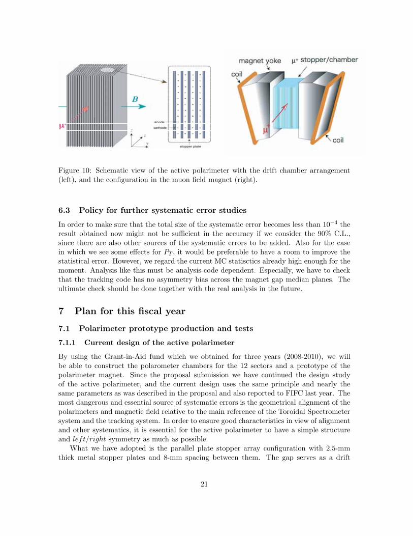
Figure 10: Schematic view of the active polarimeter with the drift chamber arrangement(left), and the configuration in the muon field magnet (right).
6.3 Policy for further systematic error studies
In order to make sure that the total size of the systematic error becomes less than 10−4 theresult obtained now might not be sufficient in the accuracy if we consider the 90% C.L.,since there are also other sources of the systematic errors to be added. Also for the casein which we see some effects for PT , it would be preferable to have a room to improve thestatistical error. However, we regard the current MC statisctics already high enough for themoment. Analysis like this must be analysis-code dependent. Especially, we have to checkthat the tracking code has no asymmetry bias across the magnet gap median planes. Theultimate check should be done together with the real analysis in the future.
7 Plan for this fiscal year
7.1 Polarimeter prototype production and tests
7.1.1 Current design of the active polarimeter
By using the Grant-in-Aid fund which we obtained for three years (2008-2010), we willbe able to construct the polarometer chambers for the 12 sectors and a prototype of thepolarimeter magnet. Since the proposal submission we have continued the design studyof the active polarimeter, and the current design uses the same principle and nearly thesame parameters as was described in the proposal and also reported to FIFC last year. Themost dangerous and essential source of systematic errors is the geometrical alignment of thepolarimeters and magnetic field relative to the main reference of the Toroidal Spectrometersystem and the tracking system. In order to ensure good characteristics in view of alignmentand other systematics, it is essential for the active polarimeter to have a simple structureand left/right symmetry as much as possible.
What we have adopted is the parallel plate stopper array configuration with 2.5-mmthick metal stopper plates and 8-mm spacing between them. The gap serves as a drift
21
chamber with anode wires in the mid-plane of the gap. About 30 layers will cover theentire width of the polarimeter. Fig.10 shows a schematic view of the polarimeter for oneof the 12 sectors. The muons enter the polarimeter parallel to the stopper plates and arestopped with an efficiency of about 85%. As we reported to the previous PAC meeting wehave already selected several candidates for the stopper metal material which have goodenough characteristics in terms of the muon spin depolarization after stopping. The incidentmuons as well as the decay positrons are tracked with the drift chamber. The positrons aretracked using several layers of the gap drift chamber, and the initial emission angle is tracedback. The angular resolution (or uncertainty) will be dominated by the multiple scatteringrather than the position resolution of the chamber, so that only a moderate resolution ofthe chamber is required. There are several issues to be solved before proceeding to the finaldesign and production of the 12 chambers. We will solve the issues by constructing a (1)several-layer prototype, and a (2) one-sector full-sized model within this fiscal year. Thetime schedule is shown in Fig.11.
7.1.2 Several-layer prototype
A prototype will be made in order to confirm the performance as a drift chamber. We willtake the same mechanical structure as the real model except that the number of layers willbe 5-10 and the number of wires will be minimized. We plan to test this prototype at theelectron test beam facility in KEK. The items to be checked are the following:
• The basic performance as a chamber will be demonstrated. The baseline design ofthe readout electronics using CMOS-ASD elements developed by the KEK detectordevelopment project will be tested.
• The position resolution for the z−coordinate determination should be measured. Be-cause of cost saving we have to make a compromise in adopting an elongated cell sizewith reduced number of anode wires. A moderate position resolution should be com-patible with the scattering effects in determining the positron emission angle. Thecorresponding timing resolution is also an important quantity for measuring the muondecay timing as accurate as possible.
• The required left/right symmetrical configuration necessarily leads to the adoptionof the anode charge ratio method for 2D readout in each layer. The performance ismeasured and fed back to the readout electronics parameters.
7.1.3 Full scale prototype
Based on the results obtained with the several-layer prototype, we will proceed to themanufacturing of a full-sized prototype for one sector. The stopper material here should bethe finally selected best candidate. The mechanical structure, wire arrangements, readoutelectronics (including the HV configuration) will be established. We aim to construct thisfull scale prototype chamber within this fiscal year and then perform a muon beam test atTRIUMF in 2009. In the test measurement, the following items will be investigated.
• We will confirm the performance as the tracker of muons which are incident parallelto the stopper plate. A forward or backward decay muon beam will be stopped in
22
the stopper plates. The simultaneous tracking of a muon and a decay positron willbe demonstrated.
• The chamber performance for a crude Michel parameter determination should bedemonstrated. Two kinds of incident muon beams are necessary: one is the standardparallel incident beam and the other is the side-wise injection to realize the y-directedpolarization. The energy threshold characteristics in determining the positron asym-metry will be studied.
• The muon incident point will be scanned in the y-direction and the dependence of thetracking performance on y will be studied. The z stopping distribution will also bevaried. The so-called fiducial region will be defined.
• By using a decay muon beam with almost zero transverse polarization, a null positronasymmetry measurement will be performed in order to verify the symmetrical struc-ture of the polarimeter. This test will also be performed by installing the polarimeterin the muon field magnet to provide data on the field symmetry.
• In order to optimize the wire electronics multiplexing scheme and also to see theperformance in the presence of background, a high-intensity run will be performedrealizing a condition such that several muons are piled-up in the polarimeter withintheir lifetime.
7.1.4 Muon field magnet
The muon field magnet is also a key element in reducing the systematic errors. The align-ment of the field vector distribution is a “direct” systematic affecting the positron asymme-try. A magnet with high mechanical precision as well as coil current distribution is required.In the first year of the polarimeter construction, a prototype of the magnet will be con-structed to determine the feasibility of the required mechanical precision. At the momenta 3D field calculation is underway to design a dipole magnet with the flattest possible fieldstrength. After the field distribution is mapped it will be used for the TRIUMF muon beamtest in 2009.
7.2 TRIUMF test experiment for MPPC radiation hardness
As was shown in the proposal and also discussed in the report to the last PAC meeting,the original plan for the target readout was to use SiMPT (Hamamatsu MPPC) in placeof the single PMT readout used in E246. We reported last time the results of simulationcalculations of the beam halo which might damage the semiconductor elements after acertain period of experimental running. The total integrated flux including π+, K+, µ+,e±, and n was estimated to be ∼ 107/mm2 after one year of full beam run under the worstcondition. On the other hand we also reported the results of radiation damage studiesusing a proton beam which showed that an exposure of the MPPC up to 8.0 Gy couldbe tolerated, corresponding to the time-integrated flux density of 5.4 × 10⁷/mm2, but nothigher. Another study using a neutron beam also indicated a similar critical flux density.As we discussed last time, the use of the MPPC is not very crucial for TREK and wesuggested an alternative choice of a multi-anode PMT. However, the use of an MPPC is
23
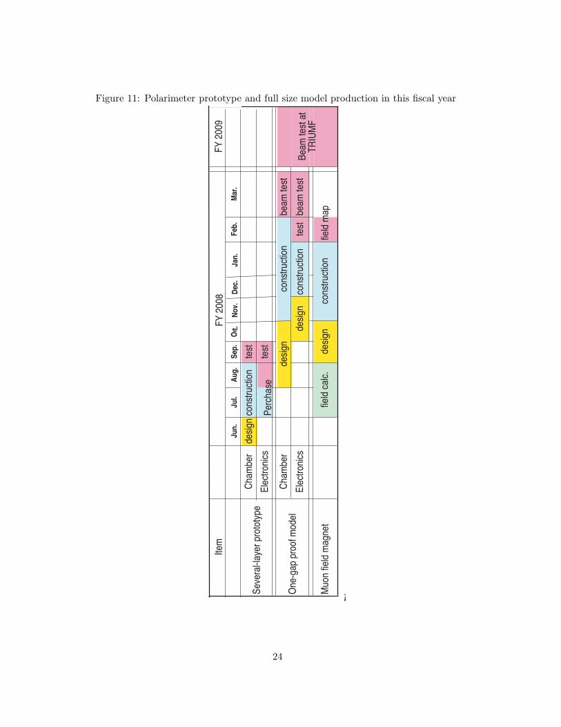
Figure 11: Polarimeter prototype and full size model production in this fiscal year
¡
24
still very attractive because it would enable a more compact setup which is quite essentialfor a high precision experiment. We have decided to pursue the problem further with amore realistic test measurement, namely using a π+ beam with a similar momentum to thedownstream particle flux expected in TREK.
We have been scheduled for 1 week of beam on the TRIUMF low energy pion channel(M13) in early July. This channel will provide a pion flux at 100 MeV/c of about 20 millionπ+/sec into a spot size of 15 × 20 mm2, which will give us a luminosity of about 130kπ+/sec/mm2 at the current focus. Hence it will take about 10-20 ksec or 4-5 hours toirradiate 108 pions into the MPPC.
7.3 Target R&D at TRIUMF
We will be able to test the scintillating fibre pulse amplitude for minimum ionizing pions(∼100 MeV/c) using the test beam port on the upgraded M13 channel. There is someexcess extruded scintillating fibre material which is available at TRIUMF which we mightbe able to use for our new target. This material has a 1mm round hole in the centre –either from T2K or KOPIO which we can machine down to a 4× 4 mm2 or 3× 3 mm2 size.The FAST experiment chose a 1 mm diameter Bicron 692 fast WLS fibre for their readoutas compared to the Kurraray Y11 WLS fibres used for the E246 ring counters. We willtest both these WLS fibres and compare them with a conventional clear fibre readout fibreusing the same PMT system. We will test both the small ∼ 1 mm2 SiPMT as used by T2Kand also the larger 3 × 3 mm2 SiPMT ( if available ) and compare them to a Hamamatsu16 channel multi-anode PMT (H6568-M16 or H8711-M16).
8 Status of the TREK collaboration
Recently a group from the Tokyo Institute of Technology has joined TREK and the currentconstituents are listed in Table 5. The number of the members has now increased to 44,not including students. The last collaboration meeting was held at KEK in February 2008,and the next meeting is planned at the University of South Carolina in October 2008.
9 Summary
In this report we emphasize that we have now received partial funding in Japan so that wecan begin the preparation/construction of the active muon polarimeter, which is the mostessential part of the upgraded detector. We have also been funded in Canada to build theactive fiber target. Although the total funding for the whole project is not yet secured, wewould like to proceed step by step with the available resources. The stage-2 condition is,however, a definite prerequisite for our colleagues in the US universities to apply for grantsthis fall. We would like to repeat our request to the PAC once again to recommend stage-2approval for our TREK experiment, so that we will be able to accelerate the internationalcooperation in preparing for the experiment, and to facilitate further funding in Japan.
We also report our continued activity in designing the detector and in our MC simulationstudies to answer some of the questions raised in the previous meetings. We hope that ourprogress will be recognized by the committee.
25
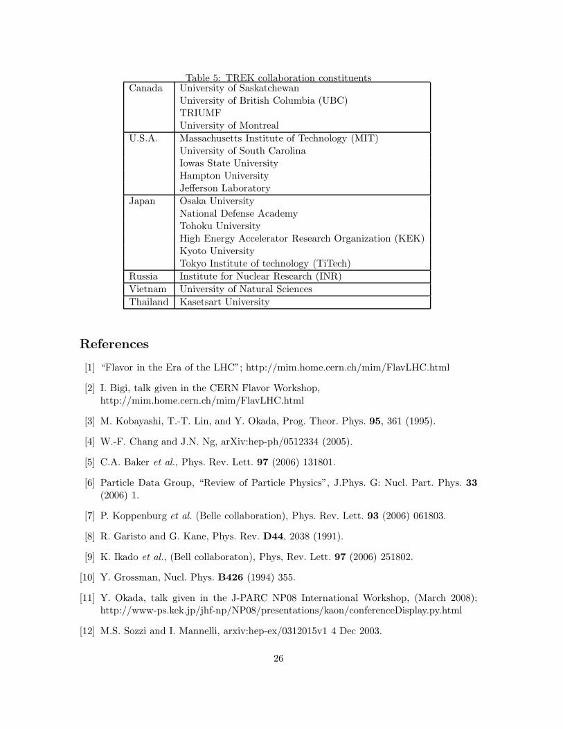
Table 5: TREK collaboration constituentsCanada University of Saskatchewan
University of British Columbia (UBC)TRIUMFUniversity of Montreal
U.S.A. Massachusetts Institute of Technology (MIT)University of South CarolinaIowas State UniversityHampton UniversityJefferson Laboratory
Japan Osaka UniversityNational Defense AcademyTohoku UniversityHigh Energy Accelerator Research Organization (KEK)Kyoto UniversityTokyo Institute of technology (TiTech)
Russia Institute for Nuclear Research (INR)Vietnam University of Natural SciencesThailand Kasetsart University
References
[1] “Flavor in the Era of the LHC”; http://mim.home.cern.ch/mim/FlavLHC.html
[2] I. Bigi, talk given in the CERN Flavor Workshop,http://mim.home.cern.ch/mim/FlavLHC.html
[3] M. Kobayashi, T.-T. Lin, and Y. Okada, Prog. Theor. Phys. 95, 361 (1995).
[4] W.-F. Chang and J.N. Ng, arXiv:hep-ph/0512334 (2005).
[5] C.A. Baker et al., Phys. Rev. Lett. 97 (2006) 131801.
[6] Particle Data Group, “Review of Particle Physics”, J.Phys. G: Nucl. Part. Phys. 33(2006) 1.
[7] P. Koppenburg et al. (Belle collaboration), Phys. Rev. Lett. 93 (2006) 061803.
[8] R. Garisto and G. Kane, Phys. Rev. D44, 2038 (1991).
[9] K. Ikado et al., (Bell collaboraton), Phys, Rev. Lett. 97 (2006) 251802.
[10] Y. Grossman, Nucl. Phys. B426 (1994) 355.
[11] Y. Okada, talk given in the J-PARC NP08 International Workshop, (March 2008);http://www-ps.kek.jp/jhf-np/NP08/presentations/kaon/conferenceDisplay.py.html
[12] M.S. Sozzi and I. Mannelli, arxiv:hep-ex/0312015v1 4 Dec 2003.
26
[13] E. Christova and M. Fabbrichesi, Phys. Lett. B315 (1993) 113.
[14] M. Fabbrichesi and F. Vissani, Phys. Rev. D55, 5334 (1997).
[15] G.-H. Wu and J.N. Ng, Phys. Lett. B392, 93 (1997).
[16] H.Dreiner, “An Introduction to Explicit R-Parity Violation” in “Perspectives on Su-persymmetry”, ed. G.L. Kane (1998).
[17] S.-L. Chen et al.. JHEP09 (2007) 044.http://jhep.sissa.it/archive/papers/jhep092007044/jhep092007044.pdf
[18] R, Barbier et al., Phys. Rept 420 (2005) 1; [hep-ph/0406039].
[19] M. Chemtob, Prog. Part. Nucl. Phys. 54 (2005) 71; [arXiv:hep-ph/0406029 2 June2008].
[20] A. Deandrea et al., JHEP 10 (2004) 038; [arXiv:hep-ph/0407216v2 20 Oct 2004].
27


![Ethernet - Amirkabir University of Technologybme2.aut.ac.ir/~towhidkhah/MPC/seminars-ppt/seminar... · Ethernet was developed at Xerox PARC between 1973 and 1974.[1][2] It was inspired](https://static.fdocument.org/doc/165x107/5e8574eb8427ad2de61103b7/ethernet-amirkabir-university-of-towhidkhahmpcseminars-pptseminar-ethernet.jpg)