Programmable Origami Strings - Northeastern UniversityOrigami, the ancient art of paper folding...
8
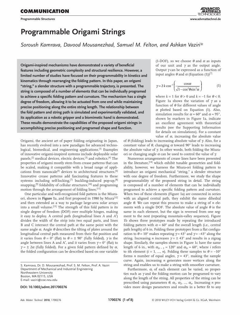
COMMUNICATION 1700276 (1 of 8) © 2018 WILEY-VCH Verlag GmbH & Co. KGaA, Weinheim www.advmattechnol.de Programmable Origami Strings Soroush Kamrava, Davood Mousanezhad, Samuel M. Felton, and Ashkan Vaziri* DOI: 10.1002/admt.201700276 (1-DOF), so we choose θ and α as inputs of our unit and γ as the output angle. Output γ can be expressed as a function of input angles θ and α (Equation (1)) [7] k γ α θ α = - - 2 cos cos 1 cos sin 1 2 2 (1) where k = 1 for θ > 0 and k = −1 for θ < 0. Figure 1a shows the variation of γ as a function of θ for different values of angle α plotted based on Equation (1). Also, simulation results for α = 60° and α = 95°, shown by markers in Figure 1a, indicate an excellent agreement with theoretical results (see the Supporting Information for details on simulations). For a constant value of α, increasing the absolute value of θ (folding) leads to increasing absolute value of γ. Also, for a constant value of θ, changing α toward 90° leads to increasing the absolute value of γ. In other words, both folding the Miura- ori or changing angle α can be used to control the value of γ. Numerous arrangements of crease lines have been presented in the literature, [14] which exhibit tunable geometries and fold- ability, however, we harness the Miura-ori folding pattern to introduce an origami mechanical “string,” a slender structure with one degree of freedom. Furthermore, we study the shape programmability of the proposed string in detail. The string is composed of a number of elements that can be individually programed to achieve a specific folding pattern and curvature. When two of these elements (Figure 1a) are connected in series with an aligned central path, they exhibit the same dihedral angle θ. We can repeat this process to make a string of n ele- ments with a single DOF. The absolute value of angle θ is the same in each element, but the sign is reversed from one seg- ment to the next (repeating mountain-valley sequence). Figure 1b shows three prototypes made by repeating the introduced folding pattern with α = 60° and the overall length (i.e., central path length) of 6 in. Folding these prototypes from a flat configu- ration to θ = 10° makes repeating γ = 43° and γ = −43° along the string. Increasing n increases γ = ± 43° and results in a zigzag shape. Similarly, the samples shown in Figure 1c have the same length of 6 in., with α 2i − 1 = 120° and α 2i = 60°, where i refers to ith element (i = 1, …, n). Folding these samples to θ = −10° forms n number of equal angles, γ = 43°, making the sample curve. Again, increasing n generates more vertices along the string and enables us to make a string with smoother curvature. Furthermore, α i of each element can be varied, so proper- ties such as γ and the folding motion can be programed to vary along the length of the string. All properties of the string can be prescribed using parameters θ, α 1 , α 2 , …, α n . Increasing n pro- vides more design parameters and results in a better fit to any Origami-inspired mechanisms have demonstrated a variety of beneficial features including geometric complexity and structural resilience. However, a limited number of studies have focused on their programmability in kinetics and kinematics through rearranging the folding pattern. In this paper, an origami “string,” a slender structure with a programmable trajectory, is presented. The string is composed of a number of elements that can be individually programed to achieve a specific folding pattern and curvature. The mechanism has a single degree of freedom, allowing it to be actuated from one end while maintaining precise positioning along the entire string length. The relationship between the fold pattern and string path is simulated and experimentally validated, and its application as a robotic gripper and a biomimetic hand is demonstrated. These results demonstrate the capabilities of the proposed origami strings in accomplishing precise positioning and programed shape and function. S. Kamrava, Dr. D. Mousanezhad, Prof. S. M. Felton, Prof. A. Vaziri Department of Mechanical and Industrial Engineering Northeastern University Boston, MA 02115, USA E-mail: [email protected] Programmable Structures Origami, the ancient art of paper folding originating in Japan, has recently evolved into a new paradigm for advanced techno- logical, biomedical, and engineering applications. [1] Examples of innovative origami-inspired systems include deployable solar panels, [2] medical devices, electric devices, [3] and robotics. [4] The properties of origami mostly stem from crease patterns that can be scaled, making it compatible with a broad range of appli- cations from nanoscale [5] devices to architectural structures. [6] Innovative crease patterns add fascinating features to these systems including self-locking, [7] buckling-induced pop-up, [8] snapping, [9] foldability of cellular structures, [10] and programing motion through the arrangement of folding lines. [11] One particular and well-recognized fold pattern is the Miura- ori, shown in Figure 1a, and first proposed in 1980 by Miura [12] and then extended as a way to package large-area solar arrays into a small volume. [13] The strength of this fold pattern is its single degree of freedom (DOF) over multiple hinges, making it easy to deploy. A central path (longitudinal lines A and A′) divides the width of the strip into two equal parts, and lines B and C intersect the central path at the same point with the same angle α. Angle θ describes the tilting of plates around the longitudinal central path measured from their flat position and it varies from θ = 0° (flat) to θ = ± 90° (fully folded). γ is the angle between lines A and A′, and it varies from γ = 0° (flat) to γ = ± 2α (fully folded). For a given fold pattern defined by α, the folded configuration can be described based on one variable Adv. Mater. Technol. 2018, 1700276
Transcript of Programmable Origami Strings - Northeastern UniversityOrigami, the ancient art of paper folding...
COMMUNICATION
1700276 (1 of 8) © 2018 WILEY-VCH Verlag GmbH & Co. KGaA, Weinheim
www.advmattechnol.de
Programmable Origami Strings
Soroush Kamrava, Davood Mousanezhad, Samuel M. Felton, and Ashkan Vaziri*
DOI: 10.1002/admt.201700276
(1-DOF), so we choose θ and α as inputs of our unit and γ as the output angle. Output γ can be expressed as a function of input angles θ and α (Equation (1))[7]
kγ αθ α
=−
−2 cos
cos
1 cos sin
1
2 2 (1)
where k = 1 for θ > 0 and k = −1 for θ < 0. Figure 1a shows the variation of γ as a function of θ for different values of angle α plotted based on Equation (1). Also, simulation results for α = 60° and α = 95°, shown by markers in Figure 1a, indicate an excellent agreement with theoretical results (see the Supporting Information for details on simulations). For a constant value of α, increasing the absolute value
of θ (folding) leads to increasing absolute value of γ. Also, for a constant value of θ, changing α toward 90° leads to increasing the absolute value of γ. In other words, both folding the Miura-ori or changing angle α can be used to control the value of γ.
Numerous arrangements of crease lines have been presented in the literature,[14] which exhibit tunable geometries and fold-ability, however, we harness the Miura-ori folding pattern to introduce an origami mechanical “string,” a slender structure with one degree of freedom. Furthermore, we study the shape programmability of the proposed string in detail. The string is composed of a number of elements that can be individually programed to achieve a specific folding pattern and curvature. When two of these elements (Figure 1a) are connected in series with an aligned central path, they exhibit the same dihedral angle θ. We can repeat this process to make a string of n ele-ments with a single DOF. The absolute value of angle θ is the same in each element, but the sign is reversed from one seg-ment to the next (repeating mountain-valley sequence). Figure 1b shows three prototypes made by repeating the introduced folding pattern with α = 60° and the overall length (i.e., central path length) of 6 in. Folding these prototypes from a flat configu-ration to θ = 10° makes repeating γ = 43° and γ = −43° along the string. Increasing n increases γ = ± 43° and results in a zigzag shape. Similarly, the samples shown in Figure 1c have the same length of 6 in., with α2i − 1 = 120° and α2i = 60°, where i refers to ith element (i = 1, …, n). Folding these samples to θ = −10° forms n number of equal angles, γ = 43°, making the sample curve. Again, increasing n generates more vertices along the string and enables us to make a string with smoother curvature.
Furthermore, αi of each element can be varied, so proper-ties such as γ and the folding motion can be programed to vary along the length of the string. All properties of the string can be prescribed using parameters θ, α1, α2, …, αn. Increasing n pro-vides more design parameters and results in a better fit to any
Origami-inspired mechanisms have demonstrated a variety of beneficial features including geometric complexity and structural resilience. However, a limited number of studies have focused on their programmability in kinetics and kinematics through rearranging the folding pattern. In this paper, an origami “string,” a slender structure with a programmable trajectory, is presented. The string is composed of a number of elements that can be individually programed to achieve a specific folding pattern and curvature. The mechanism has a single degree of freedom, allowing it to be actuated from one end while maintaining precise positioning along the entire string length. The relationship between the fold pattern and string path is simulated and experimentally validated, and its application as a robotic gripper and a biomimetic hand is demonstrated. These results demonstrate the capabilities of the proposed origami strings in accomplishing precise positioning and programed shape and function.
S. Kamrava, Dr. D. Mousanezhad, Prof. S. M. Felton, Prof. A. VaziriDepartment of Mechanical and Industrial EngineeringNortheastern UniversityBoston, MA 02115, USAE-mail: [email protected]
Programmable Structures
Origami, the ancient art of paper folding originating in Japan, has recently evolved into a new paradigm for advanced techno-logical, biomedical, and engineering applications.[1] Examples of innovative origami-inspired systems include deployable solar panels,[2] medical devices, electric devices,[3] and robotics.[4] The properties of origami mostly stem from crease patterns that can be scaled, making it compatible with a broad range of appli-cations from nanoscale[5] devices to architectural structures.[6] Innovative crease patterns add fascinating features to these systems including self-locking,[7] buckling-induced pop-up,[8] snapping,[9] foldability of cellular structures,[10] and programing motion through the arrangement of folding lines.[11]
One particular and well-recognized fold pattern is the Miura-ori, shown in Figure 1a, and first proposed in 1980 by Miura[12] and then extended as a way to package large-area solar arrays into a small volume.[13] The strength of this fold pattern is its single degree of freedom (DOF) over multiple hinges, making it easy to deploy. A central path (longitudinal lines A and A′) divides the width of the strip into two equal parts, and lines B and C intersect the central path at the same point with the same angle α. Angle θ describes the tilting of plates around the longitudinal central path measured from their flat position and it varies from θ = 0° (flat) to θ = ± 90° (fully folded). γ is the angle between lines A and A′, and it varies from γ = 0° (flat) to γ = ± 2α (fully folded). For a given fold pattern defined by α, the folded configuration can be described based on one variable
Adv. Mater. Technol. 2018, 1700276
www.advancedsciencenews.com
© 2018 WILEY-VCH Verlag GmbH & Co. KGaA, Weinheim1700276 (2 of 8)
www.advmattechnol.de
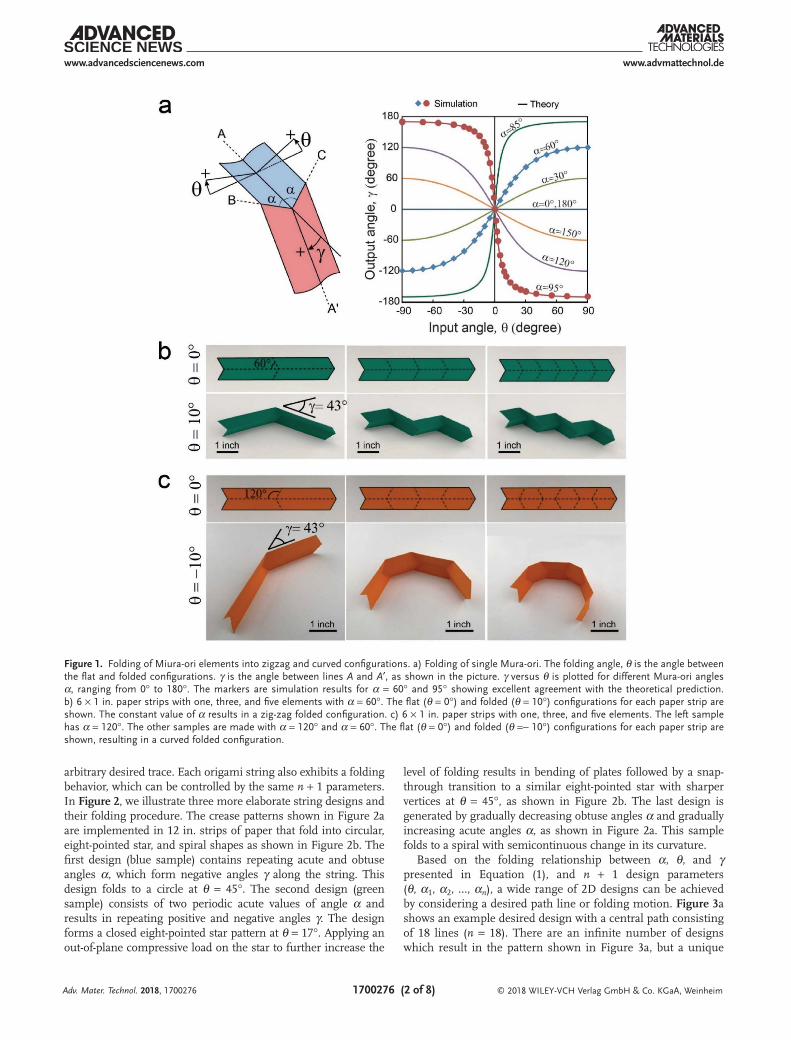
arbitrary desired trace. Each origami string also exhibits a folding behavior, which can be controlled by the same n + 1 parameters. In Figure 2, we illustrate three more elaborate string designs and their folding procedure. The crease patterns shown in Figure 2a are implemented in 12 in. strips of paper that fold into circular, eight-pointed star, and spiral shapes as shown in Figure 2b. The first design (blue sample) contains repeating acute and obtuse angles α, which form negative angles γ along the string. This design folds to a circle at θ = 45°. The second design (green sample) consists of two periodic acute values of angle α and results in repeating positive and negative angles γ. The design forms a closed eight-pointed star pattern at θ = 17°. Applying an out-of-plane compressive load on the star to further increase the
level of folding results in bending of plates followed by a snap-through transition to a similar eight-pointed star with sharper vertices at θ = 45°, as shown in Figure 2b. The last design is generated by gradually decreasing obtuse angles α and gradually increasing acute angles α, as shown in Figure 2a. This sample folds to a spiral with semicontinuous change in its curvature.
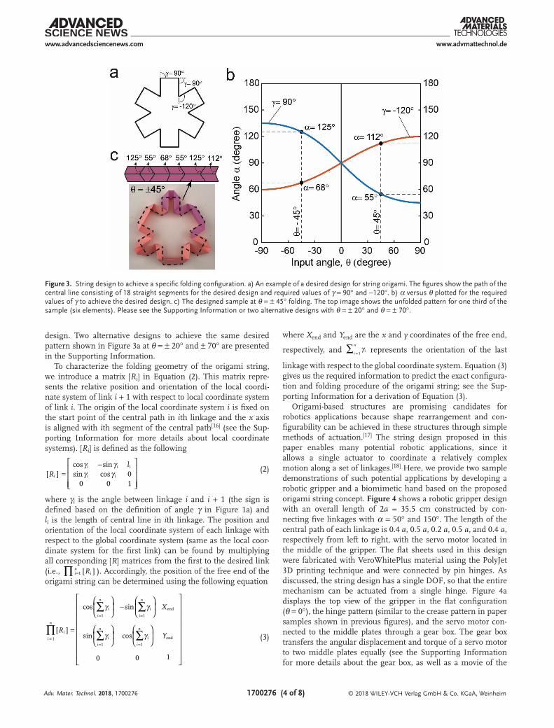
Based on the folding relationship between α, θ, and γ presented in Equation (1), and n + 1 design parameters (θ, α1, α2, …, αn), a wide range of 2D designs can be achieved by considering a desired path line or folding motion. Figure 3a shows an example desired design with a central path consisting of 18 lines (n = 18). There are an infinite number of designs which result in the pattern shown in Figure 3a, but a unique
Adv. Mater. Technol. 2018, 1700276
Figure 1. Folding of Miura-ori elements into zigzag and curved configurations. a) Folding of single Mura-ori. The folding angle, θ is the angle between the flat and folded configurations. γ is the angle between lines A and A′, as shown in the picture. γ versus θ is plotted for different Mura-ori angles α, ranging from 0° to 180°. The markers are simulation results for α = 60° and 95° showing excellent agreement with the theoretical prediction. b) 6 × 1 in. paper strips with one, three, and five elements with α = 60°. The flat (θ = 0°) and folded (θ = 10°) configurations for each paper strip are shown. The constant value of α results in a zig-zag folded configuration. c) 6 × 1 in. paper strips with one, three, and five elements. The left sample has α = 120°. The other samples are made with α = 120° and α = 60°. The flat (θ = 0°) and folded (θ =− 10°) configurations for each paper strip are shown, resulting in a curved folded configuration.
www.advancedsciencenews.com
© 2018 WILEY-VCH Verlag GmbH & Co. KGaA, Weinheim1700276 (3 of 8)
www.advmattechnol.de
design can be obtained for a given value of θ. Note that, in this example, the desired pattern is discretized, hence there are unique values for angles γ and segment length. When tracing a smooth curve, we can approximate the pattern with a set of n straight lines (of equal or unequal lengths).[15] In this math-ematical discretization scheme, the approximation becomes closer to the desired curve as n increases. In this paper, we have used lines of equal length in discretizing the curves for the sake of simplicity. Figure 3b shows the variation of angle α as
a function of angle θ, plotted for two different values of angle γ used in the given pattern (based on Equation (1)). For instance, choosing θ = ± 45° (so the original desired pattern shown in Figure 3a will be achieved by folding a flat string to 45°) results in a specific design (sign of θ changes from one element to the adjacent one) with α = 55° and 125° for vertices with γ = 90°, and α = 68° and 112° for vertices with γ = −120°, as shown in Figure 3b. Figure 3c depicts the folded pattern of this design with a central path that exactly resembles the original desired
Adv. Mater. Technol. 2018, 1700276
Figure 2. Strings that fold into circle, eight-pointed star and spiral configurations. a) 12 × 1 in. paper strings with different element designs. Blue and green samples have repeating but constant values α. In the red sample, α varies along the sample length as shown. b) Samples at different folding angle θ. The blue sample folds into a circle at θ = 45°, while the green and red samples fold to star and spiral shapes, respectively, at the same θ . The scale bar is the same for all three samples for each value of θ (each row shown).
www.advancedsciencenews.com
© 2018 WILEY-VCH Verlag GmbH & Co. KGaA, Weinheim1700276 (4 of 8)
www.advmattechnol.de
design. Two alternative designs to achieve the same desired pattern shown in Figure 3a at θ = ± 20° and ± 70° are presented in the Supporting Information.
To characterize the folding geometry of the origami string, we introduce a matrix [Ri] in Equation (2). This matrix repre-sents the relative position and orientation of the local coordi-nate system of link i + 1 with respect to local coordinate system of link i. The origin of the local coordinate system i is fixed on the start point of the central path in ith linkage and the x axis is aligned with ith segment of the central path[16] (see the Sup-porting Information for more details about local coordinate systems). [Ri] is defined as the following
cos sinsin cos 0
0 0 1R
l
i
i i i
i i
γ γγ γ[ ] =
−
(2)
where γi is the angle between linkage i and i + 1 (the sign is defined based on the definition of angle γ in Figure 1a) and li is the length of central line in ith linkage. The position and orientation of the local coordinate system of each linkage with respect to the global coordinate system (same as the local coor-dinate system for the first link) can be found by multiplying all corresponding [R] matrices from the first to the desired link (i.e., Ri
ni∏ [ ]=1 ). Accordingly, the position of the free end of the
origami string can be determined using the following equation
cos sin
sin cos
0 0 1
1
1 1
end
1 1
end
R
X
Yi
i
n
i
i
n
i
i
n
i
i
n
i
i
n∏
∑ ∑
∑ ∑
γ γ
γ γ[ ] =
−
=
= =
= = (3)
where Xend and Yend are the x and y coordinates of the free end,
respectively, and 1i
i
n∑ γ= represents the orientation of the last
linkage with respect to the global coordinate system. Equation (3) gives us the required information to predict the exact configura-tion and folding procedure of the origami string; see the Sup-porting Information for a derivation of Equation (3).
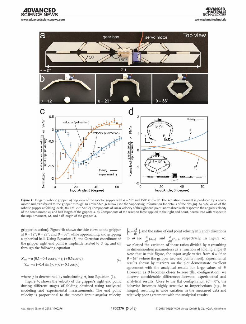
Origami-based structures are promising candidates for robotics applications because shape rearrangement and con-figurability can be achieved in these structures through simple methods of actuation.[17] The string design proposed in this paper enables many potential robotic applications, since it allows a single actuator to coordinate a relatively complex motion along a set of linkages.[18] Here, we provide two sample demonstrations of such potential applications by developing a robotic gripper and a biomimetic hand based on the proposed origami string concept. Figure 4 shows a robotic gripper design with an overall length of 2a = 35.5 cm constructed by con-necting five linkages with α = 50° and 150°. The length of the central path of each linkage is 0.4 a, 0.5 a, 0.2 a, 0.5 a, and 0.4 a, respectively from left to right, with the servo motor located in the middle of the gripper. The flat sheets used in this design were fabricated with VeroWhitePlus material using the PolyJet 3D printing technique and were connected by pin hinges. As discussed, the string design has a single DOF, so that the entire mechanism can be actuated from a single hinge. Figure 4a displays the top view of the gripper in the flat configuration (θ = 0°), the hinge pattern (similar to the crease pattern in paper samples shown in previous figures), and the servo motor con-nected to the middle plates through a gear box. The gear box transfers the angular displacement and torque of a servo motor to two middle plates equally (see the Supporting Information for more details about the gear box, as well as a movie of the
Adv. Mater. Technol. 2018, 1700276
Figure 3. String design to achieve a specific folding configuration. a) An example of a desired design for string origami. The figures show the path of the central line consisting of 18 straight segments for the desired design and required values of γ = 90° and −120°. b) α versus θ plotted for the required values of γ to achieve the desired design. c) The designed sample at θ = ± 45° folding. The top image shows the unfolded pattern for one third of the sample (six elements). Please see the Supporting Information or two alternative designs with θ = ± 20° and θ = ± 70°.
www.advancedsciencenews.com
© 2018 WILEY-VCH Verlag GmbH & Co. KGaA, Weinheim1700276 (5 of 8)
www.advmattechnol.de
gripper in action). Figure 4b shows the side views of the gripper at θ = 12°, θ = 29°, and θ = 56°, while approaching and gripping a spherical ball. Using Equation (3), the Cartesian coordinate of the gripper right end point is implicitly related to θ, α1, and α2 through the following equation
X a
Y a
γ γ γγ γ γ
( )( )
( )( )
= + + += − + −
0.1 0.4 cos 0.5cos
0.4 sin 0.5cos
end 1 2 1
end 1 2 1
(4)
where γi is determined by substituting αi into Equation (1).Figure 4c shows the velocity of the gripper’s right end point
during different stages of folding obtained using analytical modeling and experimental measurements. The end point velocity is proportional to the motor’s input angular velocity
d
dtω θ=
, and the ratios of end point velocity in x and y directions
to ω are Xθd
d( )end and Y
θd
d( )end
, respectively. In Figure 4c,
we plotted the variation of these ratios divided by a (resulting in dimensionless parameters) as a function of folding angle θ. Note that in this figure, the input angle varies from θ = 0° to θ = 63° (where the gripper two end points meet). Experimental results shown by markers on the plot demonstrate excellent agreement with the analytical results for large values of θ. However, as θ becomes closer to zero (flat configuration), we observe considerable differences between experimental and analytical results. Close to the flat configuration (θ = 0°), the behavior becomes highly sensitive to imperfections (e.g., in hinges), resulting in wide variation in the measured data and relatively poor agreement with the analytical results.
Adv. Mater. Technol. 2018, 1700276
Figure 4. Origami robotic gripper. a) Top view of the robotic gripper with α = 50° and 150° at θ = 0°. The actuation moment is produced by a servo-motor and transferred to the gripper through an embedded gear-box (see the Supporting Information for details of the design). b) Side views of the robotic gripper at folding levels, θ = 12°, 29°, 56°. c) Components of linear velocity of the right end point, normalized with respect to the angular velocity of the servo-motor, ω, and half length of the gripper, a. d) Components of the reaction force applied to the right end point, normalized with respect to the input moment, M, and half length of the gripper, a.
www.advancedsciencenews.com
© 2018 WILEY-VCH Verlag GmbH & Co. KGaA, Weinheim1700276 (6 of 8)
www.advmattechnol.de
Adv. Mater. Technol. 2018, 1700276
Next, we studied the grasping force of the proposed gripper, which is proportional to the input torque of the servo motor, denoted here by M. Neglecting gravity, the reaction forces applied from the object to the gripper end point in x and y directions can be determined based on the principle of minimum total potential energy as the following (see the Sup-porting Information for derivation of Equation (5))
dd
dd
dd
dd
dd
dd
end
end
2
end
2
end
end
2
end
2
F
M
X
X Y
F
M
Y
Y X
x
y
θ
θ θ
θ
θ θ
( )
( ) ( )
( )
( ) ( )
=
+
=
+
(5)
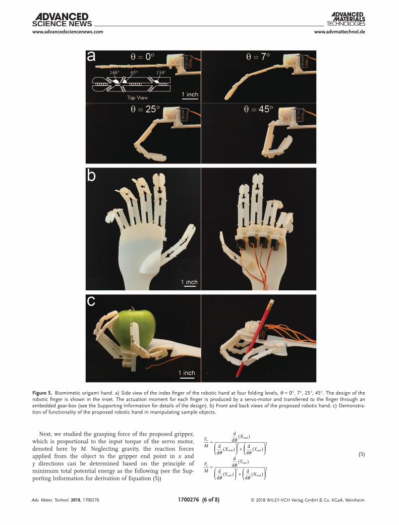
Figure 5. Biomimetic origami hand. a) Side view of the index finger of the robotic hand at four folding levels, θ = 0°, 7°, 25°, 45°. The design of the robotic finger is shown in the inset. The actuation moment for each finger is produced by a servo-motor and transferred to the finger through an embedded gear-box (see the Supporting Information for details of the design). b) Front and back views of the proposed robotic hand. c) Demonstra-tion of functionality of the proposed robotic hand in manipulating sample objects.
www.advancedsciencenews.com
© 2018 WILEY-VCH Verlag GmbH & Co. KGaA, Weinheim1700276 (7 of 8)
www.advmattechnol.de
Adv. Mater. Technol. 2018, 1700276
In Figure 4d, we plotted the variation of these ratios multi-plied by a (resulting in dimensionless parameters). Also, the insets illustrate the gripper in the flat configuration and for θ = 63°, where the gripper’s two end points meet. Note, we assumed all plates to be rigid. This simplifies the analysis, but origami can also be modeled as a structure made of deformable material.[19]
Next, we present another application of the proposed ori-gami string as a biomimetic under-actuated robotic hand, where each of the five fingers is controlled using a single actuator (Figure 5). Compared to designs based on actuating individual knuckles,[20] our design is simpler and requires only five total actuators to achieve a variety of complex move-ments in a biomimetic robotic hand.[21] Several designs for under-actuated robot hands with tendon-driven[22] or pneu-matic-driven[23] fingers have been proposed in the literature, requiring one or very low number of actuators. In these designs, the positioning of tendon-driven or pneumatic-driven robotic hands is generally sensitive to the shape of the object that is being grasped, thus hindering accurate positioning and performance.[24] In our design, the motion of each knuckle can be programed individually, making it a promising solution for manipulating small and sensi-tive objects with a relatively small number of actuators. The introduced origami-based robotic hand can be consid-ered as a generalized version of previously-introduced ori-gami-inspired forceps.[25] We selected specific values of α to mimic a typical human hand shape and movement charac-teristics. This was done by measuring the hand’s geometry and the angles between knuckles during different hand gestures. Figure 5a shows the hinge pattern of a designed robotic index finger as well as folded configurations at θ = 0°, θ = 7°, θ = 25°, and θ = 45°. The robotic index finger is made of four linkages with α1 = 134°, α2 = 65°, and α3 = 146°, respectively from right to left. The movement is controlled by a servo motor linked to the proximal linkage through a gear box. The other four fingers can be designed with a similar approach and assembled into a platform, as discussed in the Supporting Information. Figure 5b shows the front and back views of the robotic hand. The independent motion of each finger makes the origami hand compatible with a wide range of applications, such as manipulating objects with different geometries, as exemplified in Figure 5c where an apple or a pen is being held by the robotic hand.
In this paper, we introduced an origami mechanical string with programmable folding, kinetics, and kinematics. We pre-sented a simple method to design such mechanical strings to achieve a desired shape and kinematic trajectory. Precise and arbitrary motions can be controlled with a single actuator for effi-cient and lightweight positioning. This is ideal for applications that require both accuracy and sensitivity, such as surgical robots and assembly of delicate machines.[25,26] Given the scalable nature of fold patterns, the design is applicable at different length scales, including developing millimeter-sized manipulators and meter-scale space applications.[26,27] The current work paves the way to develop more novel origami strings, where integration of sensors and actuators can introduce the possibility of dynamic control, and broaden the applications of such origami-based designs.
Experimental SectionFabrication of Paper Prototypes: All paper prototypes were fabricated
out of paper with a thickness of ≈ 0.01 in., where the cuts and fold lines were made using a Silhouette CAMEO cutting machine (Silhouette America, Inc., Lindon, UT).
Fabrication of Origami Robotic Gripper and Hand: All components of origami robotic gripper and hand (including plates and gear boxes) were fabricated using PolyJet 3D printing technique (Objet Eden260V 3D printer, Stratasys Inc., Eden Prairie, MN) out of VeroWhitePlus material (Young’s modules and tensile strength of VeroWhitePlus are 2000 and 50 MPa, respectively). Origami plates were connected together by brass pin hinges with diameters of 3/64 in. A high torque servo motor (Towardpro MG-946R) and five lower torque servo motors (Emax ES-9251) were used to actuate the gripper and robotic hand through 3D printed gear boxes, respectively.
Measuring the Velocity of Gripper Free End: To measure the velocity of gripper end point, the gripper was placed in front of a gridded background and video recording was used to capture the motion of gripper during test. The position of gripper end point was measured in video frames at 0.05 s interval. The linear velocity of end point was calculated by dividing the displacement of end point between the two video frames by the corresponding time difference (i.e., 0.05 s).
Supporting InformationSupporting Information is available from the Wiley Online Library or from the author.
AcknowledgementsThis report was made possible by an NPRP award (NPRP 7-882-2-326) from the Qatar National Research Fund (a member of the Qatar Foundation). The statements herein are solely the responsibility of the authors.
Conflict of InterestThe authors declare no conflict of interest.
Keywordsbiomimetic hands, geometry of folding, origami, programmable structures, robotics grippers
Received: October 4, 2017Revised: December 14, 2017
Published online:
[1] a) N. V. Voigt, T. Tørring, A. Rotaru, M. F. Jacobsen, J. B. Ravnsbæk, R. Subramani, W. Mamdouh, J. Kjems, A. Mokhir, F. Besenbacher, Nat. Nanotechnol. 2010, 5, 200; b) D. Han, S. Pal, J. Nangreave, Z. Deng, Y. Liu, H. Yan, Science 2011, 332, 342.
[2] S. A. Zirbel, R. J. Lang, M. W. Thomson, D. A. Sigel, P. E. Walkemeyer, B. P. Trease, S. P. Magleby, L. L. Howell, J. Mech. Des. 2013, 135, 111005.
[3] a) M. Johnson, Y. Chen, S. Hovet, S. Xu, B. Wood, H. Ren, J. Tokuda, Z. T. H. Tse, Int. J. Comput. Assisted Radiol. Surg. 2017, 12, 2023. b) K. Kuribayashi, K. Tsuchiya, Z. You, D. Tomus, M. Umemoto, T. Ito, M. Sasaki, Mater. Sci. Eng. A 2006, 419, 131.
www.advancedsciencenews.com
© 2018 WILEY-VCH Verlag GmbH & Co. KGaA, Weinheim1700276 (8 of 8)
www.advmattechnol.de
Adv. Mater. Technol. 2018, 1700276
[4] a) S. M. Felton, M. T. Tolley, C. D. Onal, D. Rus, R. J. Wood, pre-sented at IEEE Int. Conf. on Robotics and Automation (ICRA), Karlsruhe, Germany, May 2013; b) C. D. Onal, R. J. Wood, D. Rus, IEEE/ASME Trans. Mechatronics 2013, 18, 430.
[5] a) S. Cranford, D. Sen, M. J. Buehler, Appl. Phys. Lett. 2009, 95, 123121; b) N. Bassik, G. M. Stern, D. H. Gracias, Appl. Phys. Lett. 2009, 95, 091901; c) J. H. Cho, M. D. Keung, N. Verellen, L. Lagae, V. V. Moshchalkov, P. Van Dorpe, D. H. Gracias, Small 2011, 7, 1943.
[6] a) T. Tachi, Origami 2011, 5, 253; b) T. Tachi, presented at Proc. of the Int. Association for Shell and Spatial Structures (IASS) Symp., Shanghai, China, November 2010; c) A. Thrall, C. Quaglia, Eng. Struct. 2014, 59, 686.
[7] S. Kamrava, D. Mousanezhad, H. Ebrahimi, R. Ghosh, A. Vaziri, Sci. Rep. 2017, 7, 46046.
[8] A. Rafsanjani, K. Bertoldi, Phys. Rev. Lett. 2017, 118, 084301.[9] a) N. P. Bende, A. A. Evans, S. Innes-Gold, L. A. Marin, I. Cohen,
R. C. Hayward, C. D. Santangelo, Proc. Natl. Acad. Sci. USA 2015, 112, 11175; b) J. L. Silverberg, J.-H. Na, A. A. Evans, B. Liu, T. C. Hull, C. D. Santangelo, R. J. Lang, R. C. Hayward, I. Cohen, Nat. Mater. 2015, 14, 389.
[10] D. Mousanezhad, S. Kamrava, A. Vaziri, Sci. Rep. 2017, 7, 14792.[11] a) S. Felton, M. Tolley, E. Demaine, D. Rus, R. Wood, Science 2014,
345, 644; b) L. A. Bowen, C. L. Grames, S. P. Magleby, L. L. Howell, R. J. Lang, J. Mech. Des. 2013, 135, 111008.
[12] K. Miura, presented at 10th Int. Conf. of Int. Cartographic Associa-tion, Tokyo, Japan, 1980.
[13] a) K. Miura, Inst. Space Astronaut. Sci. Rep. 1985, 618, 1.[14] a) T. Tachi, presented at Proc. of the IABSE-IASS Symp., London,
England, September 2011; b) L. H. Dudte, E. Vouga, T. Tachi, L. Mahadevan, Nat. Mater. 2016, 15, 583.
[15] a) P. L. Rosin, G. A. W. West, IEEE Trans. Pattern Anal. Mach. Intell. 1995, 17, 1140; b) P. L. Rosin, IEEE Trans. Pattern Anal. Mach. Intell. 1997, 19, 659.
[16] J. J. Craig, Introduction to Robotics: Mechanics and Control, Vol. 3, Pearson Prentice Hall, Upper Saddle River, NJ 2005.
[17] a) A. Firouzeh, J. Paik, Smart Mater. Struct. 2017, 26, 055035; b) E. Vander Hoff, D. Jeong, K. Lee, presented at 2014 IEEE/RSJ Int. Conf. on Intelligent Robots and Systems (IROS 2014), Chicago, September 2014.
[18] M. Sitharam, M. Wang, Comput. Aided Des. 2014, 46, 205.[19] K. Liu, G. Paulino, Proc. R. Soc. A 2017, 473, 0348.[20] F. Lotti, G. Vassura, presented at 2002 IEEE/RSJ Int. Conf. on Intel-
ligent Robots and Systems, Lausanne, September 2002.[21] a) L. Tan, S. Xie, I. Lin, T. Lin, presented at Int. Conf. on Information
and Autom. ICIA’09, Zhuhai, Macau, China June 2009; b) F. Lotti, P. Tiezzi, G. Vassura, L. Biagiotti, G. Palli, C. Melchiorri, pre-sented at Proc. of 2005 IEEE Int. Conf. on Robotics and Automation, Barcelona, Spain April 2005.
[22] a) C. Gosselin, F. Pelletier, T. Laliberte, presented at 2008 IEEE Int. Conf. on Robotics and Automation, Pasadena, CA, May 2008; b) R. R. Ma, L. U. Odhner, A. M. Dollar, presented at 2013 IEEE Int. Conf. on Robotics and Automation (ICRA), Karlsruhe, Germany, May 2013; c) V. Bundhoo, E. J. Park, presented at ICAR’05. Proc., 12th Int. Conf. on Advanced Robotics, 2005, Seattle, WA, July 2005.
[23] R. Deimel, O. Brock, Int. J. Rob. Res. 2016, 35, 161.[24] A. M. Dollar, R. D. Howe, Int. J. Rob. Res. 2010, 29, 585.[25] B. J. Edmondson, L. A. Bowen, C. L. Grames, S. P. Magleby,
L. L. Howell, T. C. Bateman, presented at ASME 2013 Conf. on Smart Materials, Adaptive Structures and Intelligent Systems, Snow-bird, UT, September 2013.
[26] M. Salerno, K. Zhang, A. Menciassi, J. S. Dai, presented at 2014 IEEE Int. Conf. on Robotics and Automation (ICRA), Hong Kong, May 2014.
[27] M. Natori, N. Katsumata, H. Yamakawa, H. Sakamoto, N. Kishimoto, presented at ASME 2013 Int. Design Engineering Technical Conf. and Computers and Information in Engineering Conf., Portland, OR, August 2013.


![OPEN ACCESS mathematics - Harvard University...Picard–Fuchs equations associated to families of elliptic curves, originating in the work of Chowla and Selberg [14]. In Section4we](https://static.fdocument.org/doc/165x107/608d154167f2fb2d7f666f88/open-access-mathematics-harvard-university-picardafuchs-equations-associated.jpg)