Prof. Tzong-Lin Wu Department of Electrical Engineering ...
19
Prof. T. L. Wu Microwave Filter Design Chp 8. Coupled Resonator Circuits Prof. Tzong-Lin Wu Department of Electrical Engineering National Taiwan University Prof. T. L. Wu Coupled Resonator Circuits Features Suitable to design narrow-band filters Design parameters 1. Coupling matrix M relationship between coupling coefficients and physical structure 2. External quality factor Q e the externally loaded input/output resonators M ij Q e
Transcript of Prof. Tzong-Lin Wu Department of Electrical Engineering ...
Prof. T. L. Wu
Microwave Filter Design
Chp 8. Coupled Resonator Circuits
Prof. Tzong-Lin Wu
Department of Electrical Engineering
National Taiwan University
Prof. T. L. Wu
Coupled Resonator Circuits
Features Suitable to design narrow-band filters
Design parameters1. Coupling matrix M
relationship between coupling coefficients and physical structure
2. External quality factor Qe
the externally loaded input/output resonators
Mij Qe
Prof. T. L. Wu
General Coupling Matrix for Coupled-Resonators (1/4)
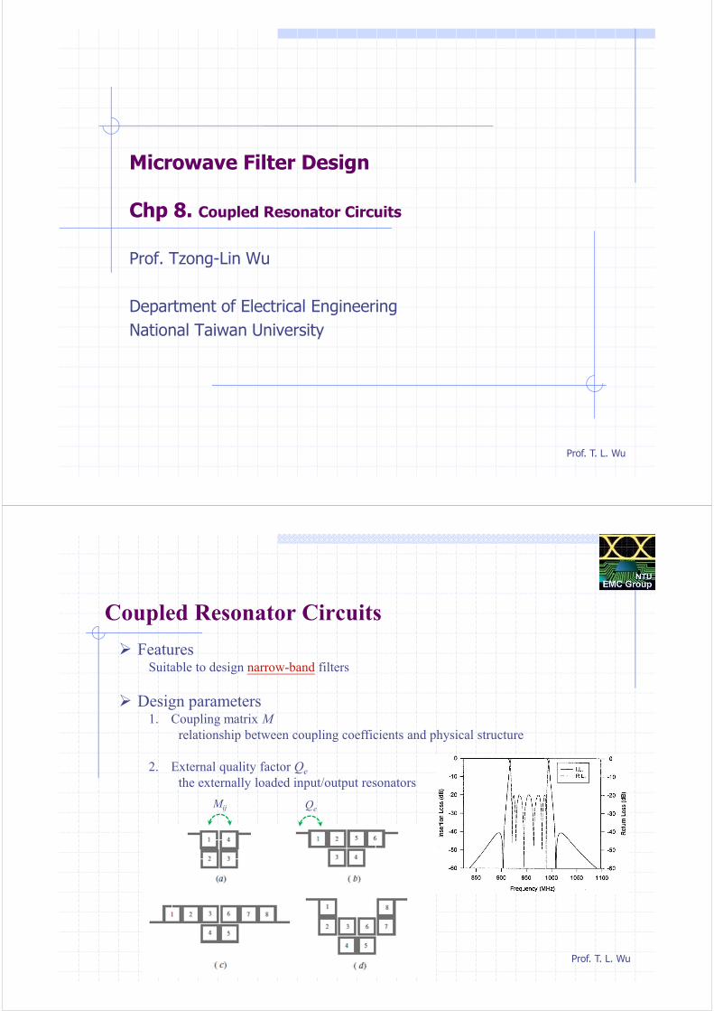
Loop Equation Formulation (magnetic coupling)
KVL:
or
Prof. T. L. Wu
General Coupling Matrix for Coupled-Resonators (2/4)
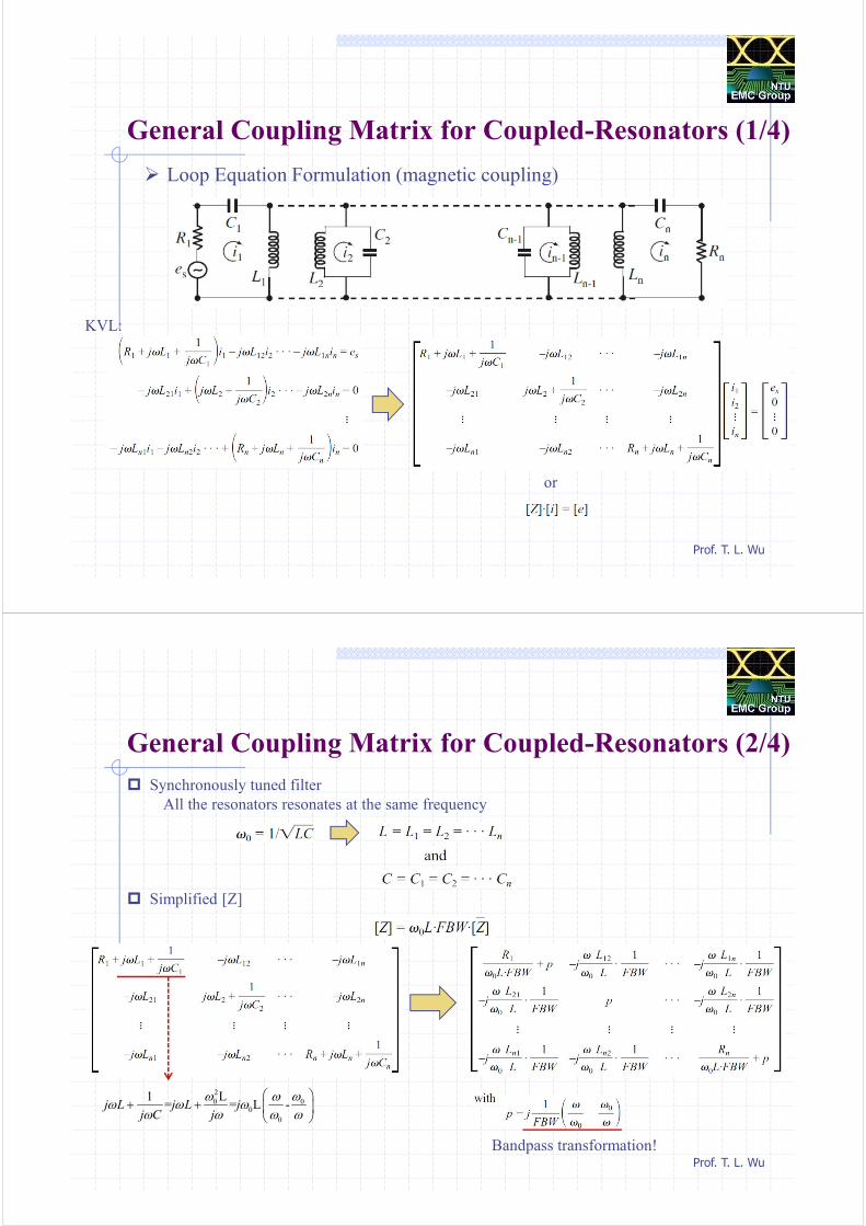
Synchronously tuned filter
All the resonators resonates at the same frequency
Simplified [Z]
2
0 00
0
1 L= = L -j L j L j
j C j
ω ω ωω ω ω
ω ω ω ω
+ +
Bandpass transformation!
Prof. T. L. Wu
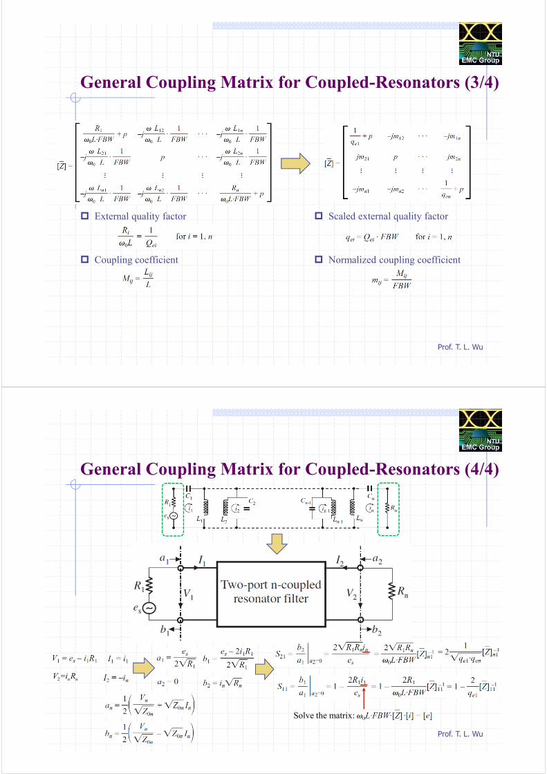
General Coupling Matrix for Coupled-Resonators (3/4)
External quality factor
Coupling coefficient
Scaled external quality factor
Normalized coupling coefficient
Prof. T. L. Wu
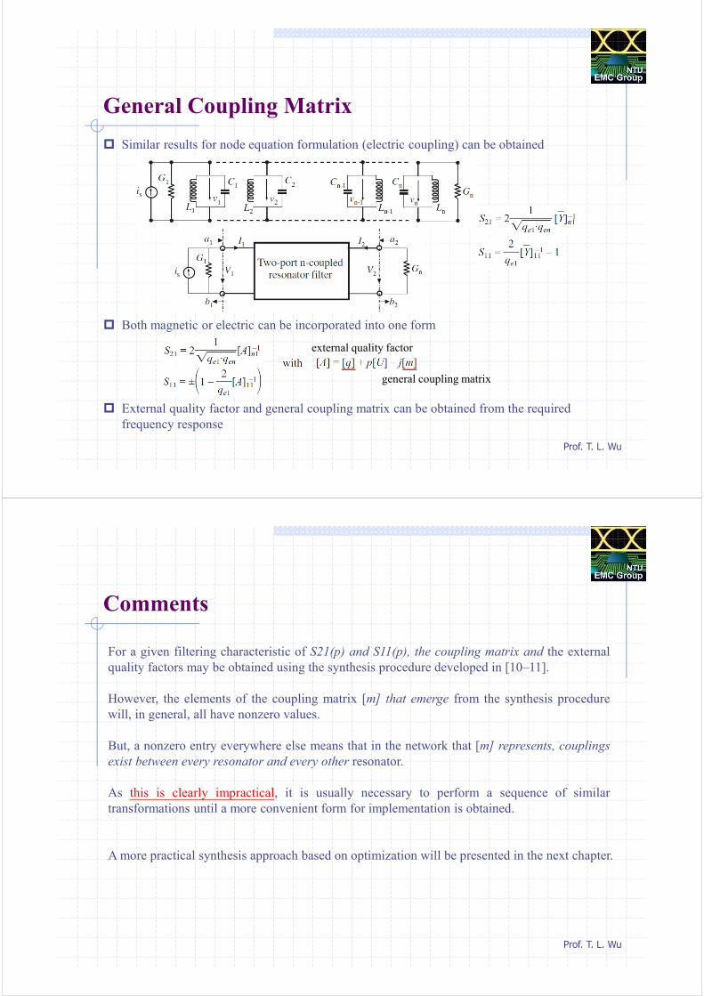
General Coupling Matrix for Coupled-Resonators (4/4)
2 = n nV i R
Solve the matrix:
Prof. T. L. Wu
General Coupling Matrix
Similar results for node equation formulation (electric coupling) can be obtained
Both magnetic or electric can be incorporated into one form
External quality factor and general coupling matrix can be obtained from the required
frequency response
general coupling matrix
external quality factor
Prof. T. L. Wu
Comments
For a given filtering characteristic of S21(p) and S11(p), the coupling matrix and the external
quality factors may be obtained using the synthesis procedure developed in [10–11].
However, the elements of the coupling matrix [m] that emerge from the synthesis procedure
will, in general, all have nonzero values.
But, a nonzero entry everywhere else means that in the network that [m] represents, couplings
exist between every resonator and every other resonator.
As this is clearly impractical, it is usually necessary to perform a sequence of similar
transformations until a more convenient form for implementation is obtained.
A more practical synthesis approach based on optimization will be presented in the next chapter.
Prof. T. L. Wu
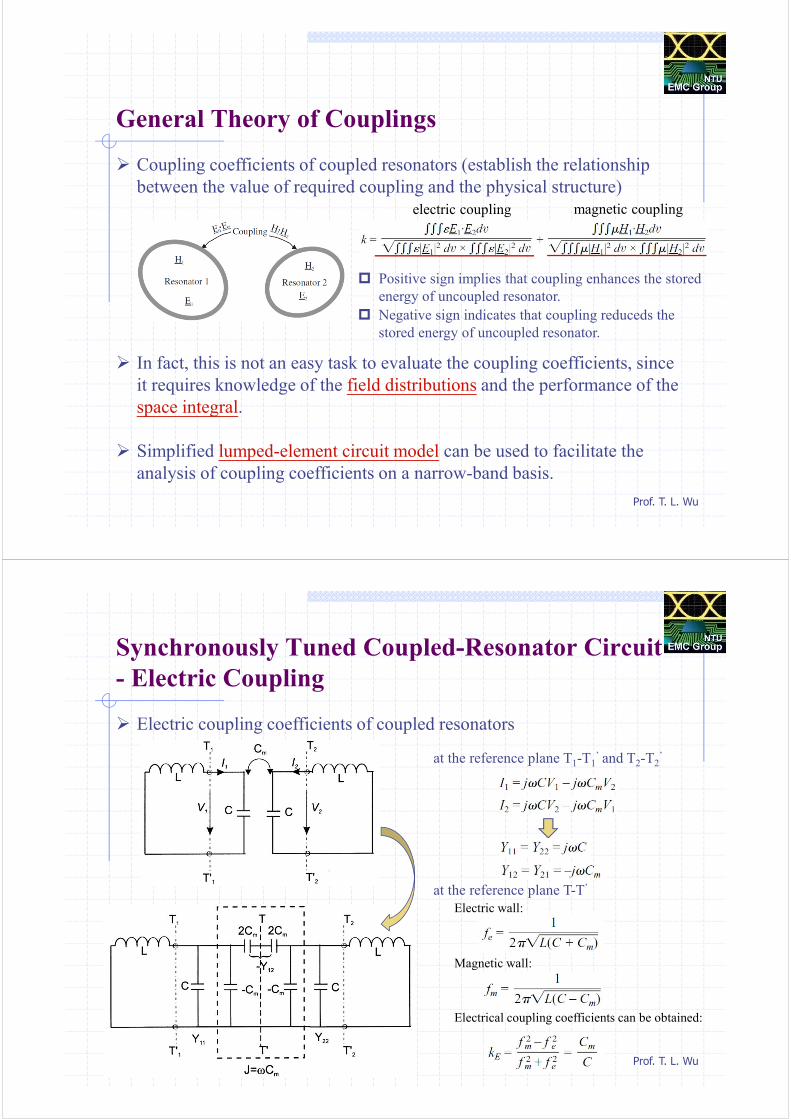
General Theory of Couplings
Coupling coefficients of coupled resonators (establish the relationship
between the value of required coupling and the physical structure)
In fact, this is not an easy task to evaluate the coupling coefficients, since
it requires knowledge of the field distributions and the performance of the
space integral.
Simplified lumped-element circuit model can be used to facilitate the
analysis of coupling coefficients on a narrow-band basis.
electric coupling magnetic coupling
Positive sign implies that coupling enhances the stored
energy of uncoupled resonator.
Negative sign indicates that coupling reduceds the
stored energy of uncoupled resonator.
Prof. T. L. Wu
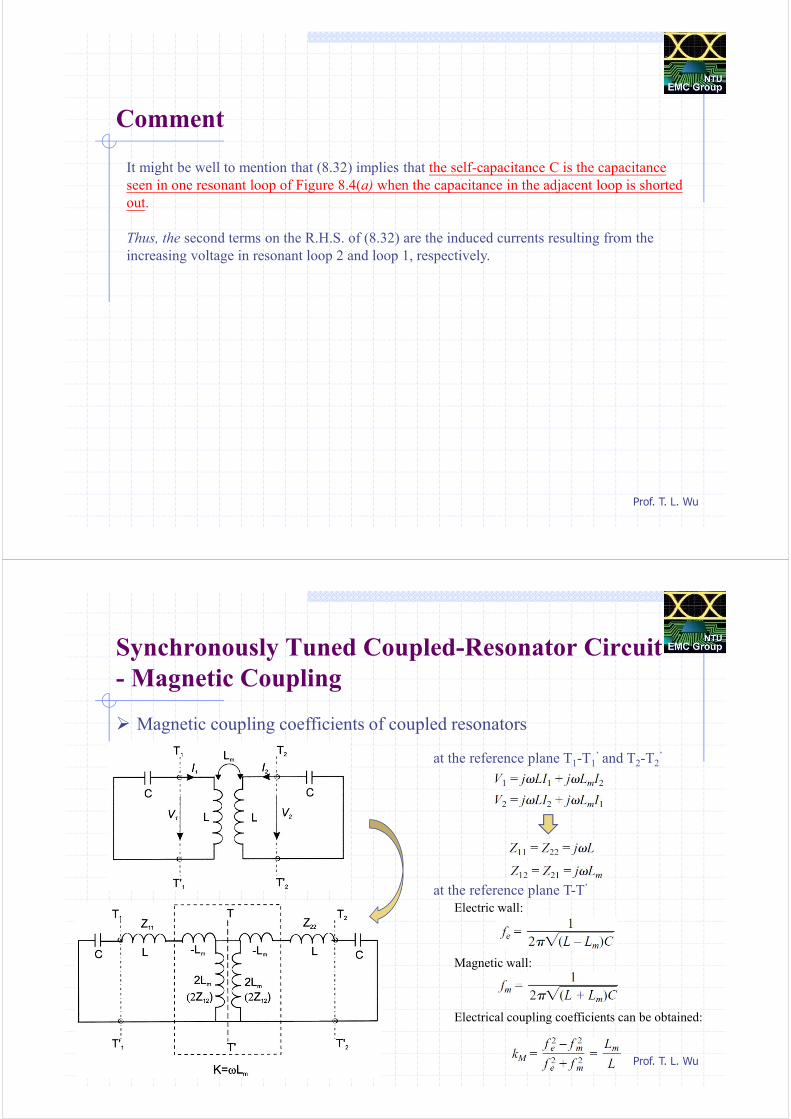
Synchronously Tuned Coupled-Resonator Circuit
- Electric Coupling
Electric coupling coefficients of coupled resonators
at the reference plane T1-T1’ and T2-T2
’
at the reference plane T-T’
Electric wall:
Magnetic wall:
Electrical coupling coefficients can be obtained:
Prof. T. L. Wu
Comment
It might be well to mention that (8.32) implies that the self-capacitance C is the capacitance
seen in one resonant loop of Figure 8.4(a) when the capacitance in the adjacent loop is shorted
out.
Thus, the second terms on the R.H.S. of (8.32) are the induced currents resulting from the
increasing voltage in resonant loop 2 and loop 1, respectively.
Prof. T. L. Wu
Synchronously Tuned Coupled-Resonator Circuit
- Magnetic Coupling
Magnetic coupling coefficients of coupled resonators
at the reference plane T1-T1’ and T2-T2
’
at the reference plane T-T’
Electric wall:
Magnetic wall:
Electrical coupling coefficients can be obtained:
Prof. T. L. Wu
Comment
The equations in (8.37) also imply that the self-inductance L is the inductance seen
in one resonant loop of Figure 8.5(a) when the adjacent loop is open-circuited.
Thus, the second terms on the R.H.S. of (8.37) are the induced voltages resulting
from the increasing current in loops 2 and 1, respectively.
It should be noticed that the two loop currents in Figure 8.5(a) flow in the opposite directions,
so that the voltage drops due to the mutual inductance have a positive sign.
Prof. T. L. Wu
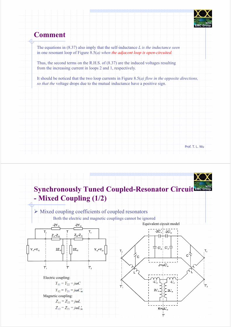
Synchronously Tuned Coupled-Resonator Circuit
- Mixed Coupling (1/2)
Mixed coupling coefficients of coupled resonators
Both the electric and magnetic couplings cannot be ignored
Electric coupling:
Magnetic coupling:
Equivalent circuit model
Prof. T. L. Wu
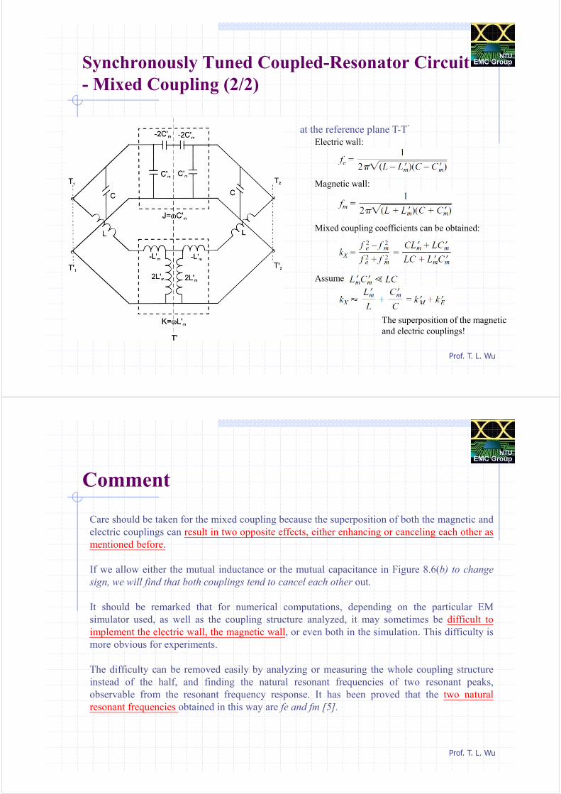
Synchronously Tuned Coupled-Resonator Circuit
- Mixed Coupling (2/2)
at the reference plane T-T’
Electric wall:
Magnetic wall:
Mixed coupling coefficients can be obtained:
Assume
The superposition of the magnetic
and electric couplings!
Prof. T. L. Wu
Comment
Care should be taken for the mixed coupling because the superposition of both the magnetic and
electric couplings can result in two opposite effects, either enhancing or canceling each other as
mentioned before.
If we allow either the mutual inductance or the mutual capacitance in Figure 8.6(b) to change
sign, we will find that both couplings tend to cancel each other out.
It should be remarked that for numerical computations, depending on the particular EM
simulator used, as well as the coupling structure analyzed, it may sometimes be difficult to
implement the electric wall, the magnetic wall, or even both in the simulation. This difficulty is
more obvious for experiments.
The difficulty can be removed easily by analyzing or measuring the whole coupling structure
instead of the half, and finding the natural resonant frequencies of two resonant peaks,
observable from the resonant frequency response. It has been proved that the two natural
resonant frequencies obtained in this way are fe and fm [5].
Prof. T. L. Wu
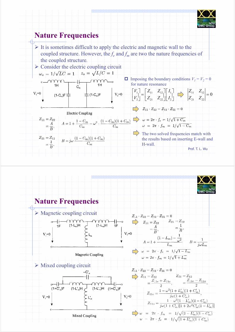
Nature Frequencies
It is sometimes difficult to apply the electric and magnetic wall to the
coupled structure. However, the fe and fm are two the nature frequencies of
the coupled structure.
Consider the electric coupling circuit
Imposing the boundary conditions V1 = V2 = 0
for nature resonance
1 11 12 1
2 21 22 2
V Z Z I
V Z Z I
=
11 12
21 22
0Z Z
Z Z=
The two solved frequencies match with
the results based on inserting E-wall and
H-wall.
Prof. T. L. Wu
Nature Frequencies
Magnetic coupling circuit
Mixed coupling circuit
Prof. T. L. Wu
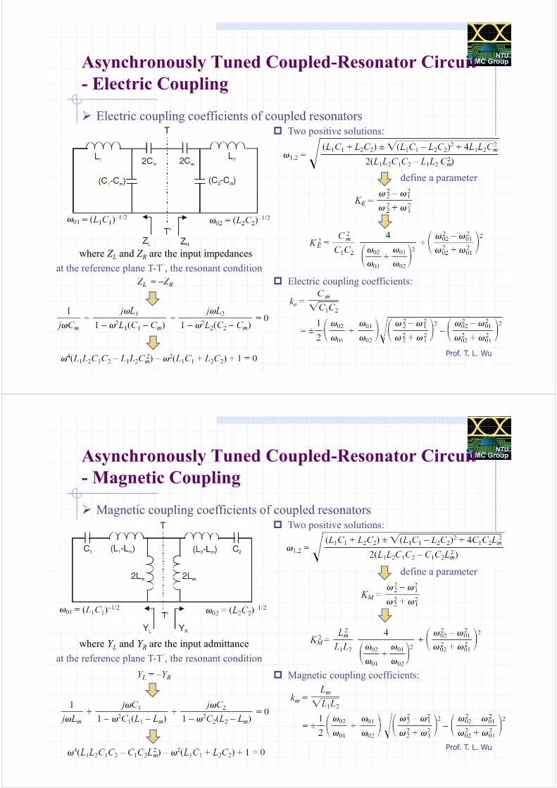
Asynchronously Tuned Coupled-Resonator Circuit
- Electric Coupling
Electric coupling coefficients of coupled resonators
at the reference plane T-T’, the resonant condition
where ZL and ZR are the input impedances
Two positive solutions:
define a parameter
Electric coupling coefficients:
Prof. T. L. Wu
Asynchronously Tuned Coupled-Resonator Circuit
- Magnetic Coupling
Magnetic coupling coefficients of coupled resonators
at the reference plane T-T’, the resonant condition
where YL and YR are the input admittance
Two positive solutions:
define a parameter
Magnetic coupling coefficients:
Prof. T. L. Wu
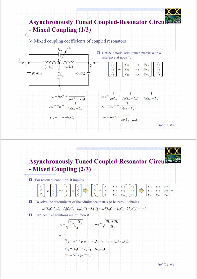
Asynchronously Tuned Coupled-Resonator Circuit
- Mixed Coupling (1/3)
Mixed coupling coefficients of coupled resonators
Define a nodal admittance matrix with a
reference at node “0”
Prof. T. L. Wu
Asynchronously Tuned Coupled-Resonator Circuit
- Mixed Coupling (2/3)
For resonant condition, it implies
To solve the determinant of the admittance matrix to be zero, it obtains
Two positive solutions are of interest
Prof. T. L. Wu
Asynchronously Tuned Coupled-Resonator Circuit
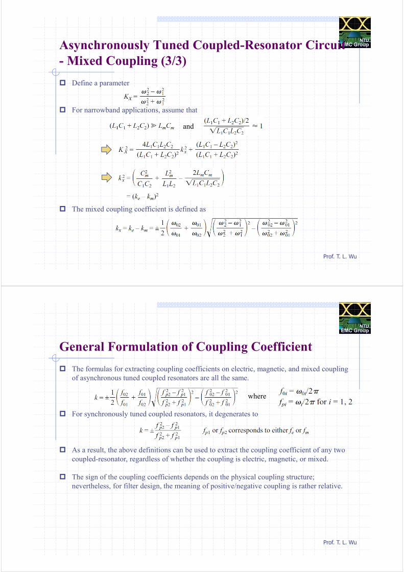
- Mixed Coupling (3/3)
Define a parameter
For narrowband applications, assume that
The mixed coupling coefficient is defined as
and
Prof. T. L. Wu
General Formulation of Coupling Coefficient
The formulas for extracting coupling coefficients on electric, magnetic, and mixed coupling
of asynchronous tuned coupled resonators are all the same.
For synchronously tuned coupled resonators, it degenerates to
As a result, the above definitions can be used to extract the coupling coefficient of any two
coupled-resonator, regardless of whether the coupling is electric, magnetic, or mixed.
The sign of the coupling coefficients depends on the physical coupling structure;
nevertheless, for filter design, the meaning of positive/negative coupling is rather relative.
where
Prof. T. L. Wu
CommentThis means that if we refer to one particular coupling as the positive coupling, and then
the negative coupling would imply that its phase response is opposite to that of the positive
coupling.
The phase response of a coupling may be found from the S parameters of its associated
coupling structure.
Alternatively, the derivations in Section 8.2.1 have suggested another simple way to find
whether the two coupling structures have the same signs or not.
This can be done by applying either the electric or magnetic wall to find the fe or fm of both the
coupling structures. If the frequency shifts of fe or fm with respect to their individual uncoupled
resonant frequencies are in the same direction, the resultant coupling coefficients will have the
same signs, if not the opposite signs.
Prof. T. L. Wu
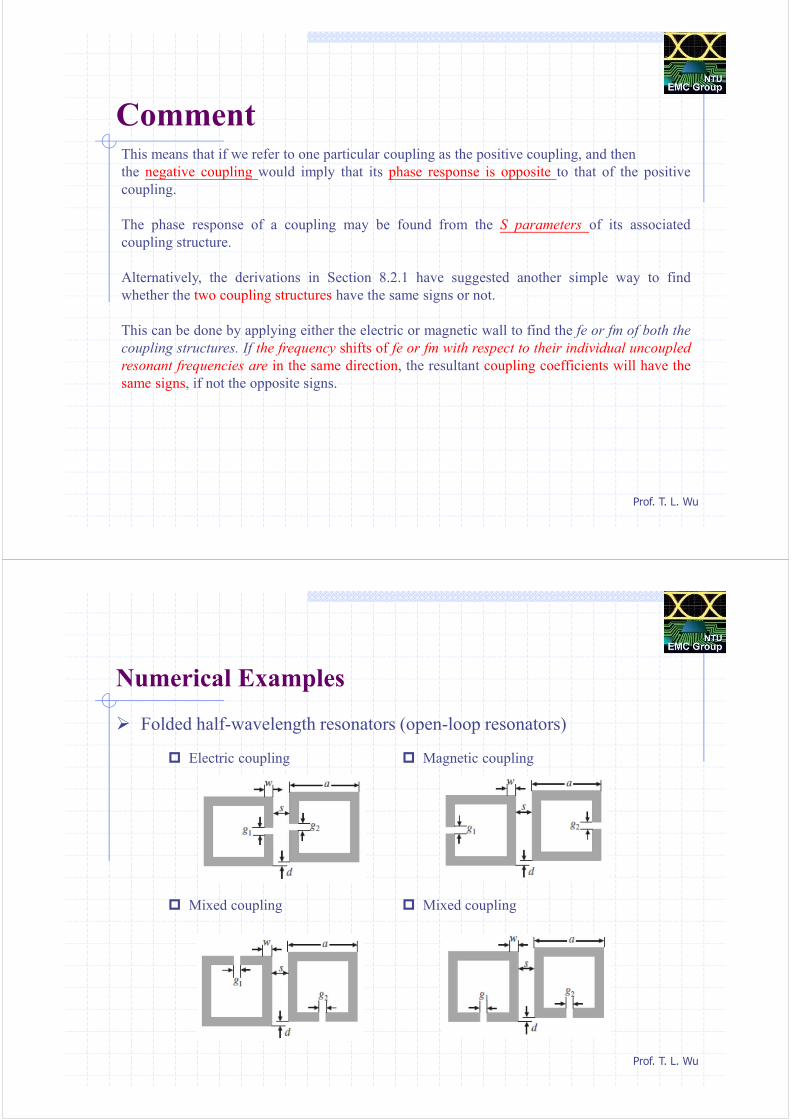
Numerical Examples
Folded half-wavelength resonators (open-loop resonators)
Electric coupling Magnetic coupling
Mixed coupling Mixed coupling
Prof. T. L. Wu
Extracting Coupling Coefficients
- Synchronous Tuning
Folded half-wavelength resonators (open-loop resonators) Electric coupling Magnetic coupling
1 2513.3 MHzpf = 2 2540.7 MHzpf = 1 2484.2 MHzpf = 2 2567.9 MHzpf =
2 2
2 1
2 2
2 1
0.01084p p
p p
f fk
f f
−= =
+
2 2
2 1
2 2
2 1
0.03313p p
p p
f fk
f f
−= =
+
fp1 fp2fp1 fp2
Prof. T. L. Wu
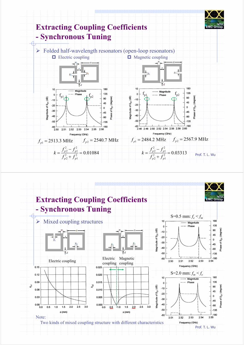
Extracting Coupling Coefficients
- Synchronous Tuning
Mixed coupling structures
Electric
coupling
Magnetic
coupling
S=0.5 mm: fe < fm
S=2.0 mm: fm < fe
Note:
Two kinds of mixed coupling structure with different characteristics
Electric coupling
Prof. T. L. Wu
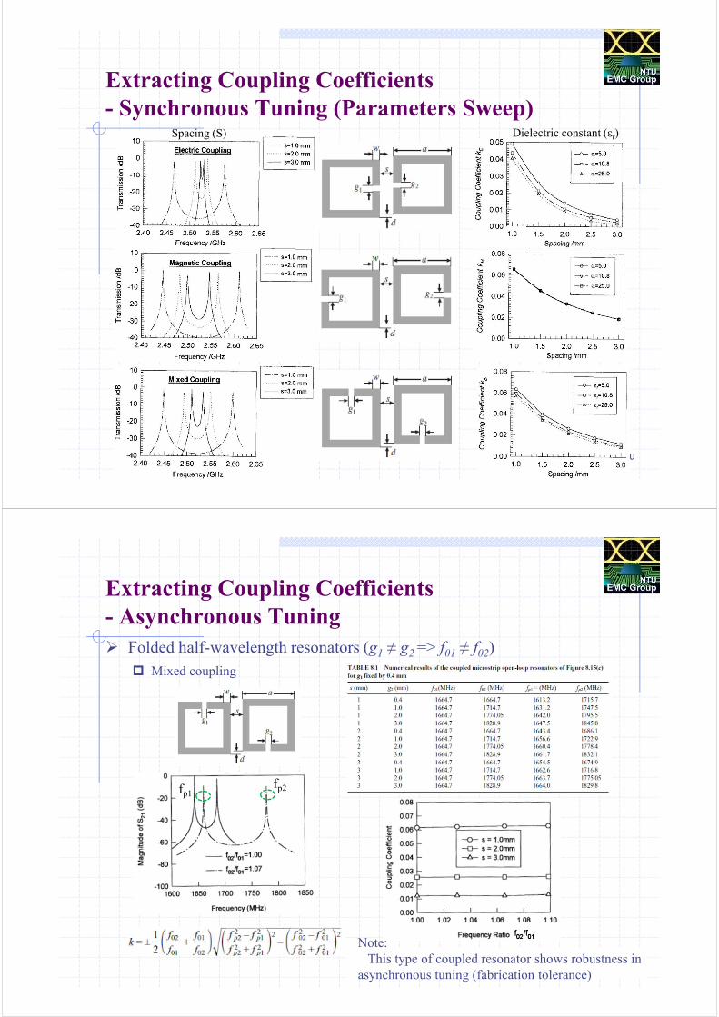
Extracting Coupling Coefficients
- Synchronous Tuning (Parameters Sweep)Spacing (S) Dielectric constant (εr)
Prof. T. L. Wu
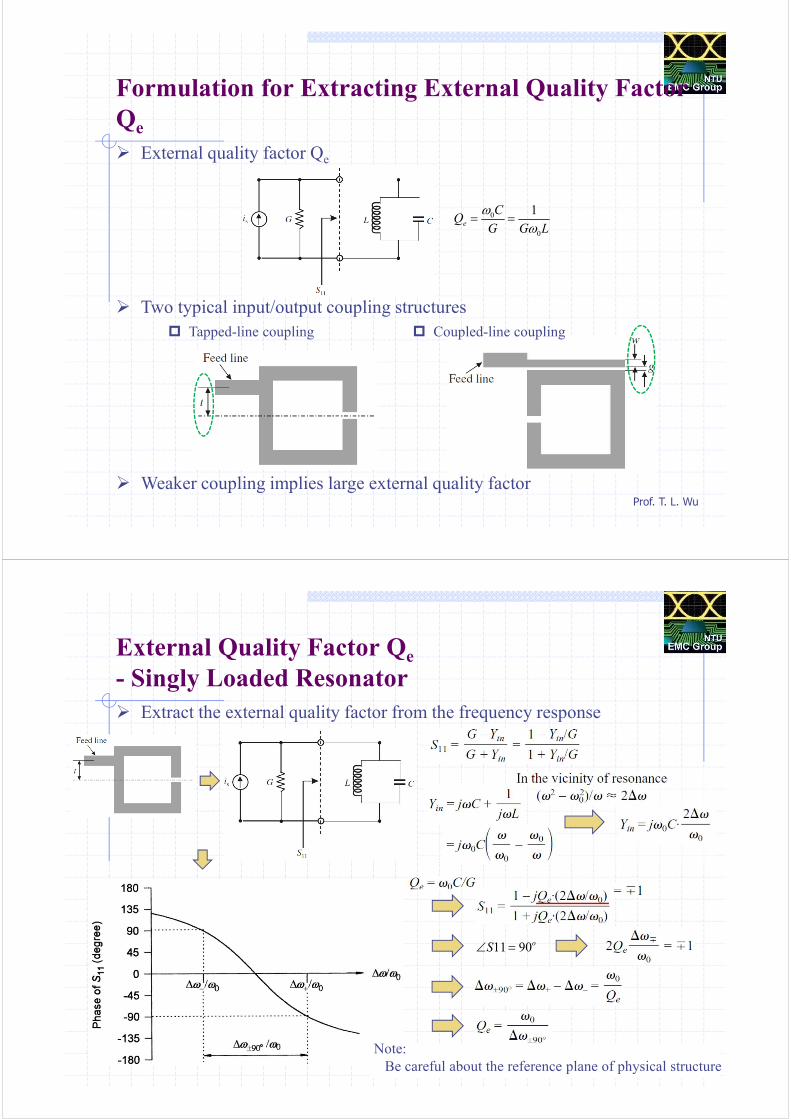
Extracting Coupling Coefficients
- Asynchronous Tuning
Folded half-wavelength resonators (g1 ≠ g2 => f01 ≠ f02)
Mixed coupling
fp1fp2
Note:
This type of coupled resonator shows robustness in
asynchronous tuning (fabrication tolerance)
Prof. T. L. Wu
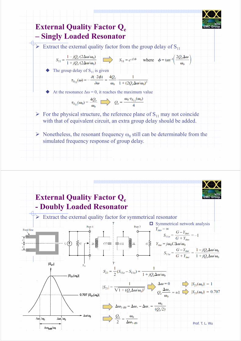
Formulation for Extracting External Quality Factor
Qe
External quality factor Qe
Two typical input/output coupling structures
Weaker coupling implies large external quality factor
Tapped-line coupling Coupled-line coupling
0
0
1e
CQ
G G L
ω
ω= =
Prof. T. L. Wu
External Quality Factor Qe
- Singly Loaded Resonator
Extract the external quality factor from the frequency response
11 90oS∠ =
Note:
Be careful about the reference plane of physical structure
Prof. T. L. Wu
External Quality Factor Qe
– Singly Loaded Resonator
Extract the external quality factor from the group delay of S11
The group delay of S11 is given
At the resonance ∆ω = 0, it reaches the maximum value
For the physical structure, the reference plane of S11 may not coincide
with that of equivalent circuit, an extra group delay should be added.
Nonetheless, the resonant frequency ω0 still can be determinable from the
simulated frequency response of group delay.
where
Prof. T. L. Wu
External Quality Factor Qe
- Doubly Loaded Resonator
Extract the external quality factor for symmetrical resonator Symmetrical network analysis
Prof. T. L. Wu
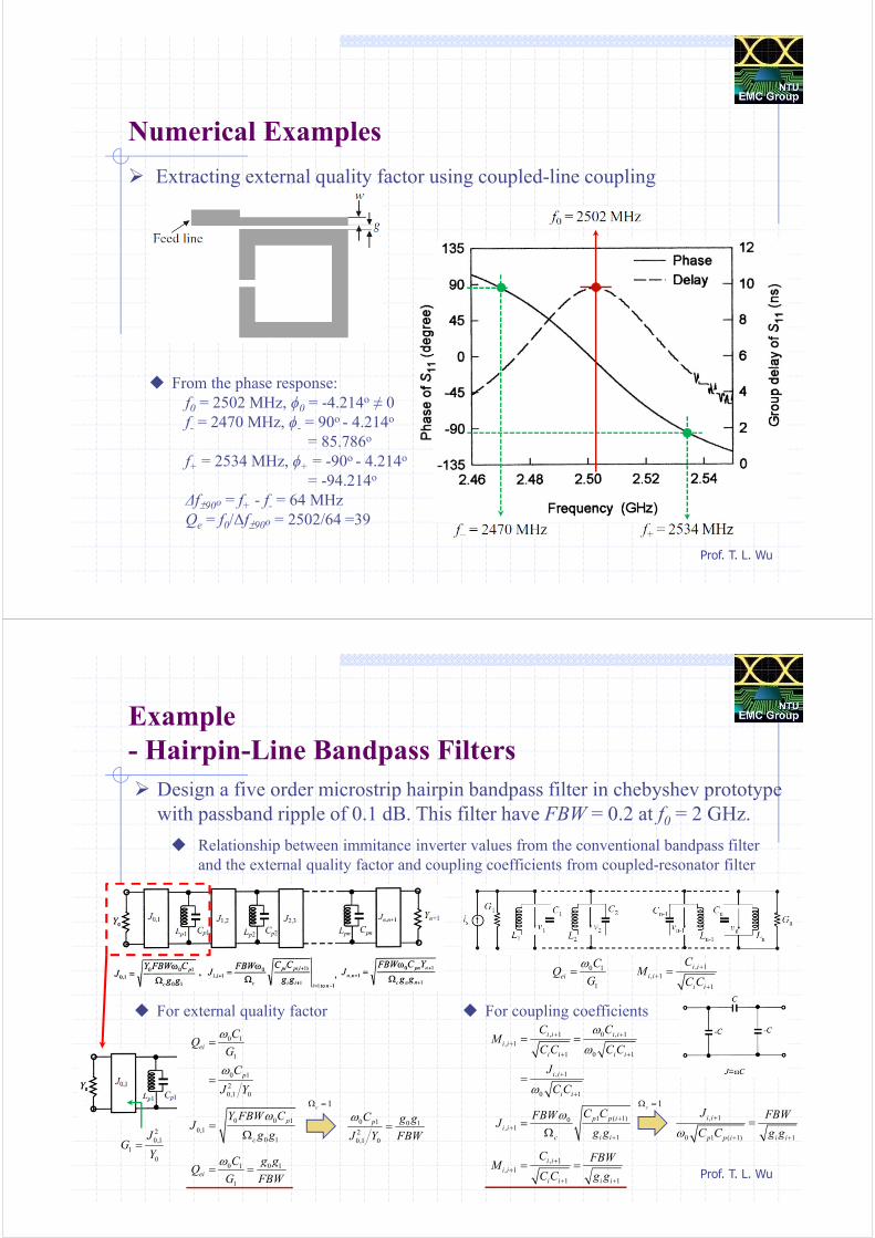
Numerical Examples
Extracting external quality factor using coupled-line coupling
From the phase response:
f0 = 2502 MHz, ϕ0 = -4.214o ≠ 0
f- = 2470 MHz, ϕ- = 90o - 4.214o
= 85.786o
f+ = 2534 MHz, ϕ+ = -90o - 4.214o
= -94.214o
∆f±90o = f+ - f- = 64 MHz
Qe = f0/∆f±90o = 2502/64 =39
Prof. T. L. Wu
Example
- Hairpin-Line Bandpass Filters
Design a five order microstrip hairpin bandpass filter in chebyshev prototype
with passband ripple of 0.1 dB. This filter have FBW = 0.2 at f0 = 2 GHz.
Relationship between immitance inverter values from the conventional bandpass filter
and the external quality factor and coupling coefficients from coupled-resonator filter
0 1
1
ei
CQ
G
ω=
, 1
, 1
1
i i
i i
i i
CM
C C
+
+
+
=
For external quality factor
2
0,1
1
0
JG
Y=
0 1
1
0 1
2
0,1 0
ei
p
CQ
G
C
J Y
ω
ω
=
=
0 0 1
0,1
0 1
p
c
Y FBW CJ
g g
ω=
Ω0 1 0 1
2
0,1 0
pC g g
FBWJ Y
ω=
0 1 0 1
1
ei
C g gQ
G FBW
ω= =
For coupling coefficients
, 1 0 , 1
, 1
1 0 1
, 1
0 1
i i i i
i i
i i i i
i i
i i
C CM
C C C C
J
C C
ω
ω
ω
+ +
+
+ +
+
+
= =
=
1 ( 1)0
, 1
1
p p i
i i
c i i
C CFBWJ
g g
ω +
+
+
=Ω
, 1
0 1 ( 1) 1
i i
p p i i i
J FBW
C C g gω
+
+ +
=
, 1
, 1
1 1
i i
i i
i i i i
C FBWM
C C g g
+
+
+ +
= =
1cΩ =1cΩ =
Prof. T. L. Wu
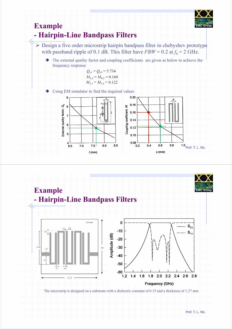
Example
- Hairpin-Line Bandpass Filters
Design a five order microstrip hairpin bandpass filter in chebyshev prototype
with passband ripple of 0.1 dB. This filter have FBW = 0.2 at f0 = 2 GHz.
The external quality factor and coupling coefficients are given as below to achieve the
frequency response
Using EM simulator to find the required values
Prof. T. L. Wu
Example
- Hairpin-Line Bandpass Filters
The microstrip is designed on a substrate with a dielectric constant of 6.15 and a thickness of 1.27 mm