Principles of Photovoltaics (PV) Dr. Mohamed Fawzy Aboud ... · Dr. Mohamed Fawzy Aboud Sustainable...
24
Principles of Photovoltaics (PV) Dr. Mohamed Fawzy Aboud Sustainable Energy Technologies center (SET)
Transcript of Principles of Photovoltaics (PV) Dr. Mohamed Fawzy Aboud ... · Dr. Mohamed Fawzy Aboud Sustainable...
Principles of Photovoltaics (PV)
Dr. Mohamed Fawzy Aboud
Sustainable Energy Technologies center (SET)
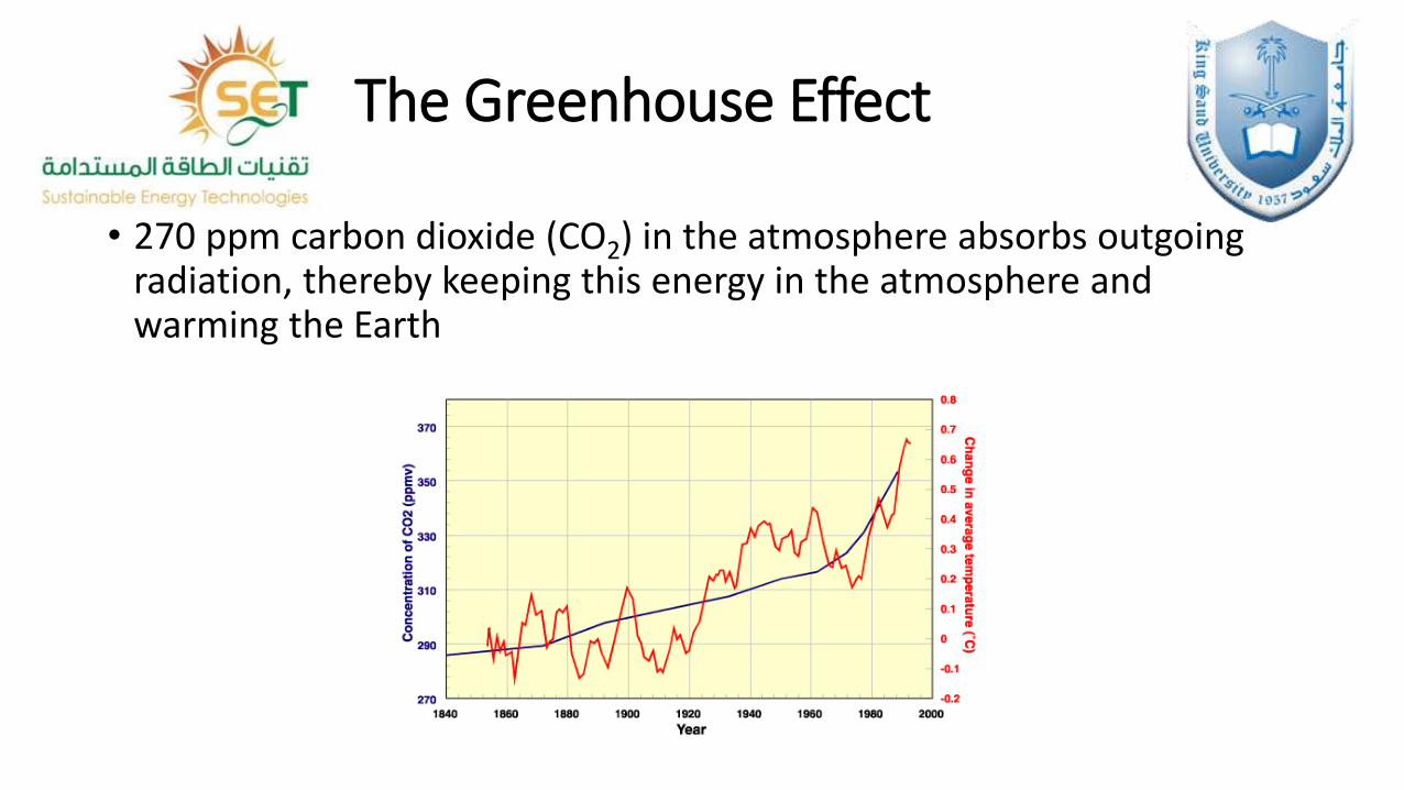
The Greenhouse Effect
• 270 ppm carbon dioxide (CO2) in the atmosphere absorbs outgoing radiation, thereby keeping this energy in the atmosphere and warming the Earth
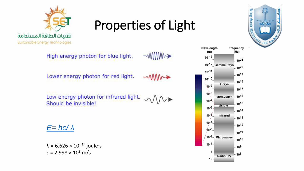
Properties of Light
E= hc/ λ
h = 6.626 × 10 -34 joule·sc = 2.998 × 10⁸ m/s
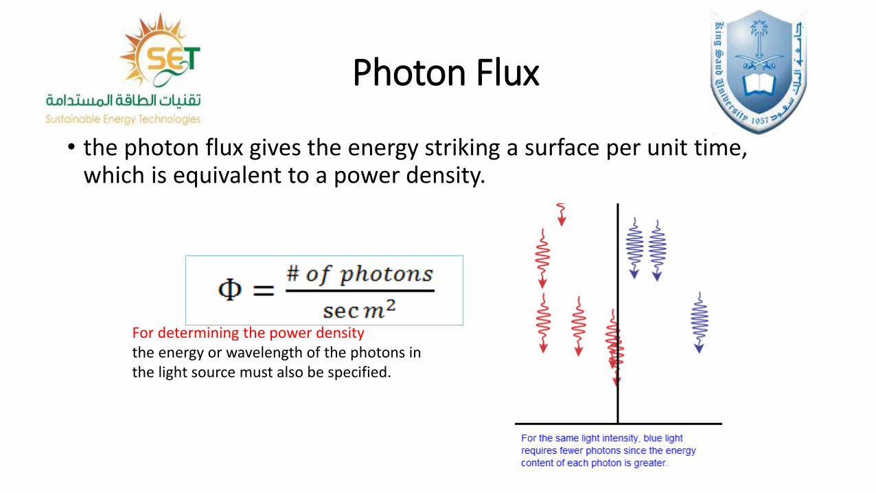
Photon Flux
• the photon flux gives the energy striking a surface per unit time, which is equivalent to a power density.
For determining the power densitythe energy or wavelength of the photons in the light source must also be specified.
Solar Radiation at the Earth's Surface
• atmospheric effects, including absorption and scattering
• local variations in the atmosphere, such as water vapour, clouds, and pollution
• latitude of the location
• the season of the year and the time of day.
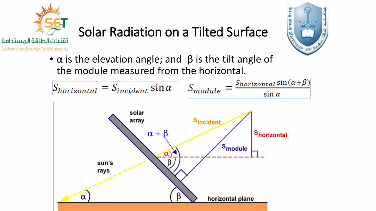
Solar Radiation on a Tilted Surface
• α is the elevation angle; and β is the tilt angle of the module measured from the horizontal.
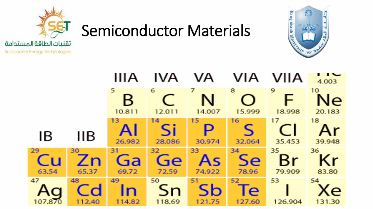
Semiconductor Materials
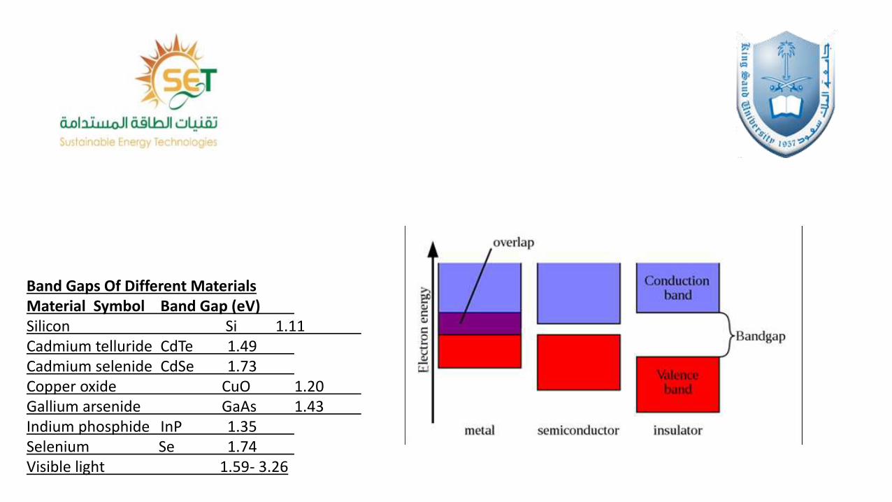
Band Gaps Of Different MaterialsMaterial Symbol Band Gap (eV)Silicon Si 1.11Cadmium telluride CdTe 1.49Cadmium selenide CdSe 1.73Copper oxide CuO 1.20Gallium arsenide GaAs 1.43Indium phosphide InP 1.35Selenium Se 1.74Visible light 1.59- 3.26
Absorption of Light
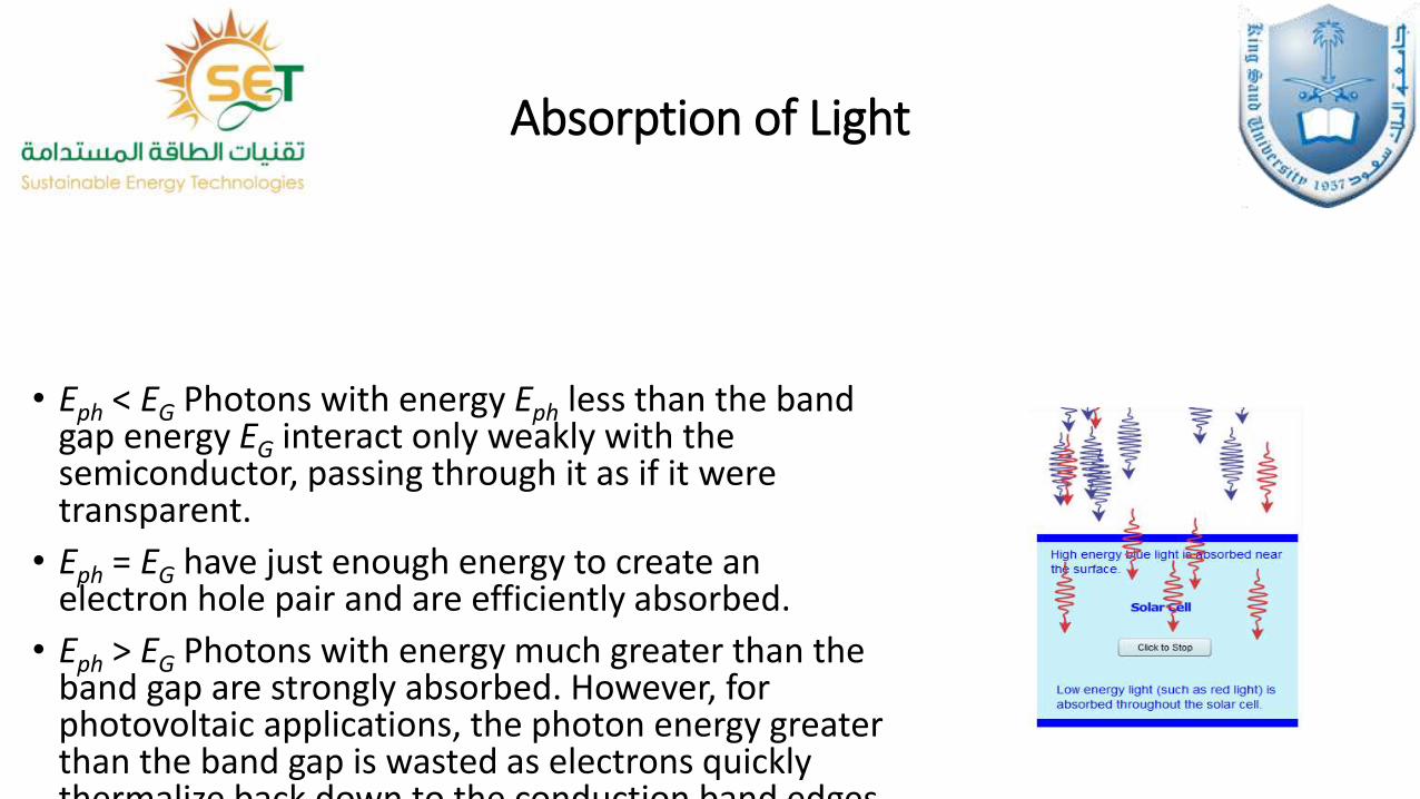
• Eph < EG Photons with energy Eph less than the band gap energy EG interact only weakly with the semiconductor, passing through it as if it were transparent.
• Eph = EG have just enough energy to create an electron hole pair and are efficiently absorbed.
• Eph > EG Photons with energy much greater than the band gap are strongly absorbed. However, for photovoltaic applications, the photon energy greater than the band gap is wasted as electrons quickly thermalize back down to the conduction band edges.
Absorption Depth
• The absorption depth is given by the inverse of the absorption coefficient, and describes how deeply light penetrates into a semiconductor before being absorbed.
• Higher energy light is of a shorter wavelength and has a shorter absorption depth than lower energy light, which is not as readily absorbed, and has a greater absorption depth.
• Absorption depth affects aspects of solar cell design, such as the thickness of the semiconductor material.
Generation Rate
• The generation of an electron-hole pair can be calculated at any location within the solar cell, at any wavelength of light, or for the entire standard solar spectrum.
• Generation is the greatest at the surface of the material, where the majority of the light is absorbed.
• Because the light used in PV applications contains many different wavelengths, many different generation rates must be taken into account when designing a solar cell.
Types of Recombination&Lifetime
• The lifetime of a semiconductor is contingent upon the recombination rate, which is dependent upon the concentration of minority carriers.
• The lifetime of the material takes into account the different types of recombination.
• Lifetime is an indicator of the efficiency of a solar cell, and thus is a key consideration in choosing materials for solar cells.
• Eventually, electrons lose energy and stabilize back to the valence band, recombining with a hole.
• There are three types of recombination; Radiative, Shockley-Read-Hall, and Auger.
• Auger and Shockley-Read-Hall recombination dominate in silicon-based solar cells.
• Among other factors, recombination is associated with the lifetime of the material, and thus of the solar cell.
Solar Cell Structure
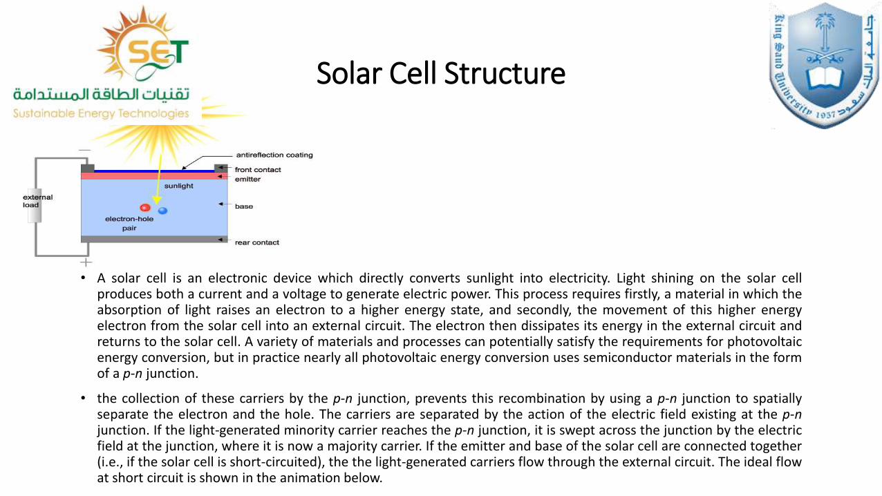
• A solar cell is an electronic device which directly converts sunlight into electricity. Light shining on the solar cellproduces both a current and a voltage to generate electric power. This process requires firstly, a material in which theabsorption of light raises an electron to a higher energy state, and secondly, the movement of this higher energyelectron from the solar cell into an external circuit. The electron then dissipates its energy in the external circuit andreturns to the solar cell. A variety of materials and processes can potentially satisfy the requirements for photovoltaicenergy conversion, but in practice nearly all photovoltaic energy conversion uses semiconductor materials in the formof a p-n junction.
• the collection of these carriers by the p-n junction, prevents this recombination by using a p-n junction to spatiallyseparate the electron and the hole. The carriers are separated by the action of the electric field existing at the p-njunction. If the light-generated minority carrier reaches the p-n junction, it is swept across the junction by the electricfield at the junction, where it is now a majority carrier. If the emitter and base of the solar cell are connected together(i.e., if the solar cell is short-circuited), the the light-generated carriers flow through the external circuit. The ideal flowat short circuit is shown in the animation below.
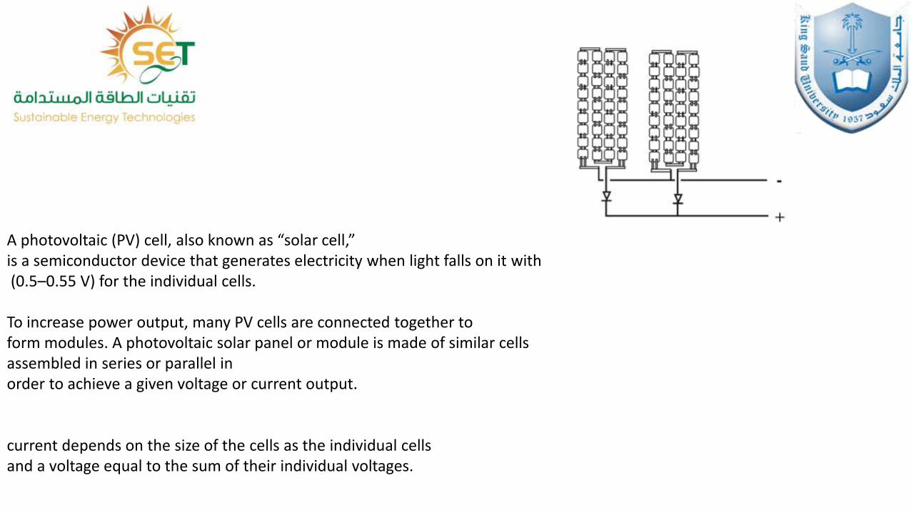
A photovoltaic (PV) cell, also known as “solar cell,”is a semiconductor device that generates electricity when light falls on it with(0.5–0.55 V) for the individual cells.
To increase power output, many PV cells are connected together to form modules. A photovoltaic solar panel or module is made of similar cells assembled in series or parallel in order to achieve a given voltage or current output.
current depends on the size of the cells as the individual cells and a voltage equal to the sum of their individual voltages.
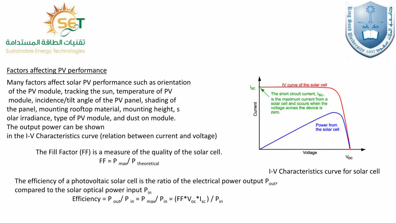
Factors affecting PV performance
I-V Characteristics curve for solar cell
Many factors affect solar PV performance such as orientationof the PV module, tracking the sun, temperature of PVmodule, incidence/tilt angle of the PV panel, shading of
the panel, mounting rooftop material, mounting height, solar irradiance, type of PV module, and dust on module. The output power can be shown in the I-V Characteristics curve (relation between current and voltage)
The Fill Factor (FF) is a measure of the quality of the solar cell.FF = P max/ P theoretical
The efficiency of a photovoltaic solar cell is the ratio of the electrical power output Pout, compared to the solar optical power input Pin
Efficiency = P out/ P in = P max/ Pin = (FF*Voc*Isc ) / Pin
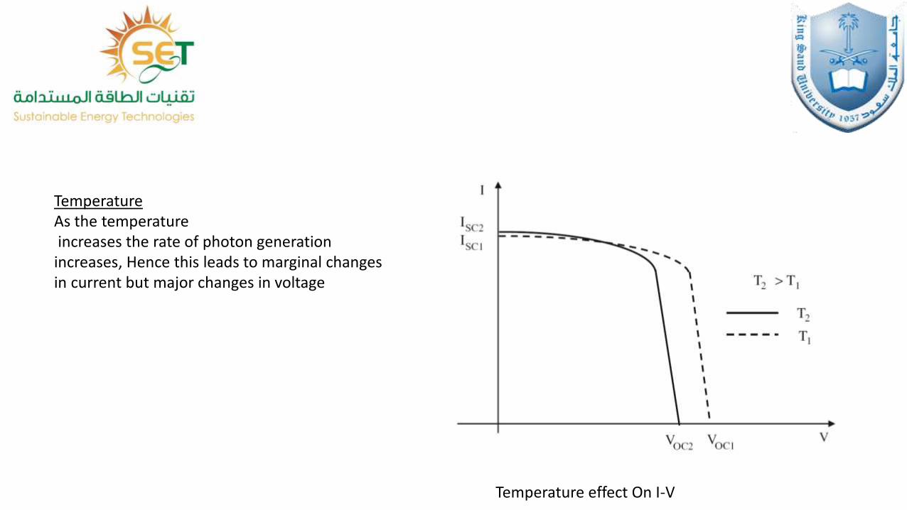
TemperatureAs the temperatureincreases the rate of photon generation
increases, Hence this leads to marginal changes in current but major changes in voltage
Temperature effect On I-V
Shading
Shading mainly affects the series connected PV module.
Since the current produced by shaded portion is less as
compared to the illuminated portion. But current in series must
be same illuminated cells current forced the shaded portion
current to increase result in hotspot and may cause damage to
the entire module. For this problem to overcome parallel
configuration is used for arranging the PV module. In parallel
the output is not so affected as in case of series configuration.
Since the current in parallel is not same in the entire panel but
voltage should be same. It is experimentally proved that parallel
configuration is better than series.
Dusts
Dusts impact solar photovoltaic (PV) performance because they block the transmission of sunlight
and affect the temperature of the module in addition to surface corrosion.
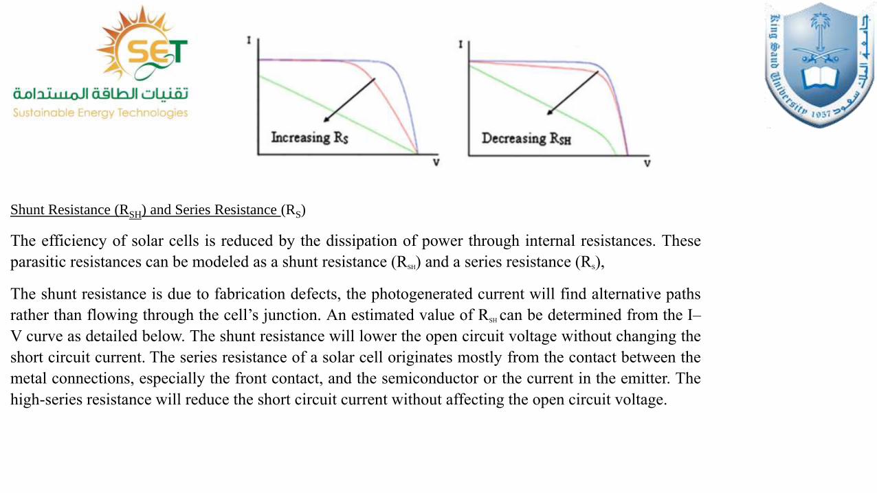
Shunt Resistance (RSH) and Series Resistance (RS)
The efficiency of solar cells is reduced by the dissipation of power through internal resistances. These
parasitic resistances can be modeled as a shunt resistance (RSH) and a series resistance (RS),
The shunt resistance is due to fabrication defects, the photogenerated current will find alternative paths
rather than flowing through the cell’s junction. An estimated value of RSH can be determined from the I–
V curve as detailed below. The shunt resistance will lower the open circuit voltage without changing the
short circuit current. The series resistance of a solar cell originates mostly from the contact between the
metal connections, especially the front contact, and the semiconductor or the current in the emitter. The
high-series resistance will reduce the short circuit current without affecting the open circuit voltage.
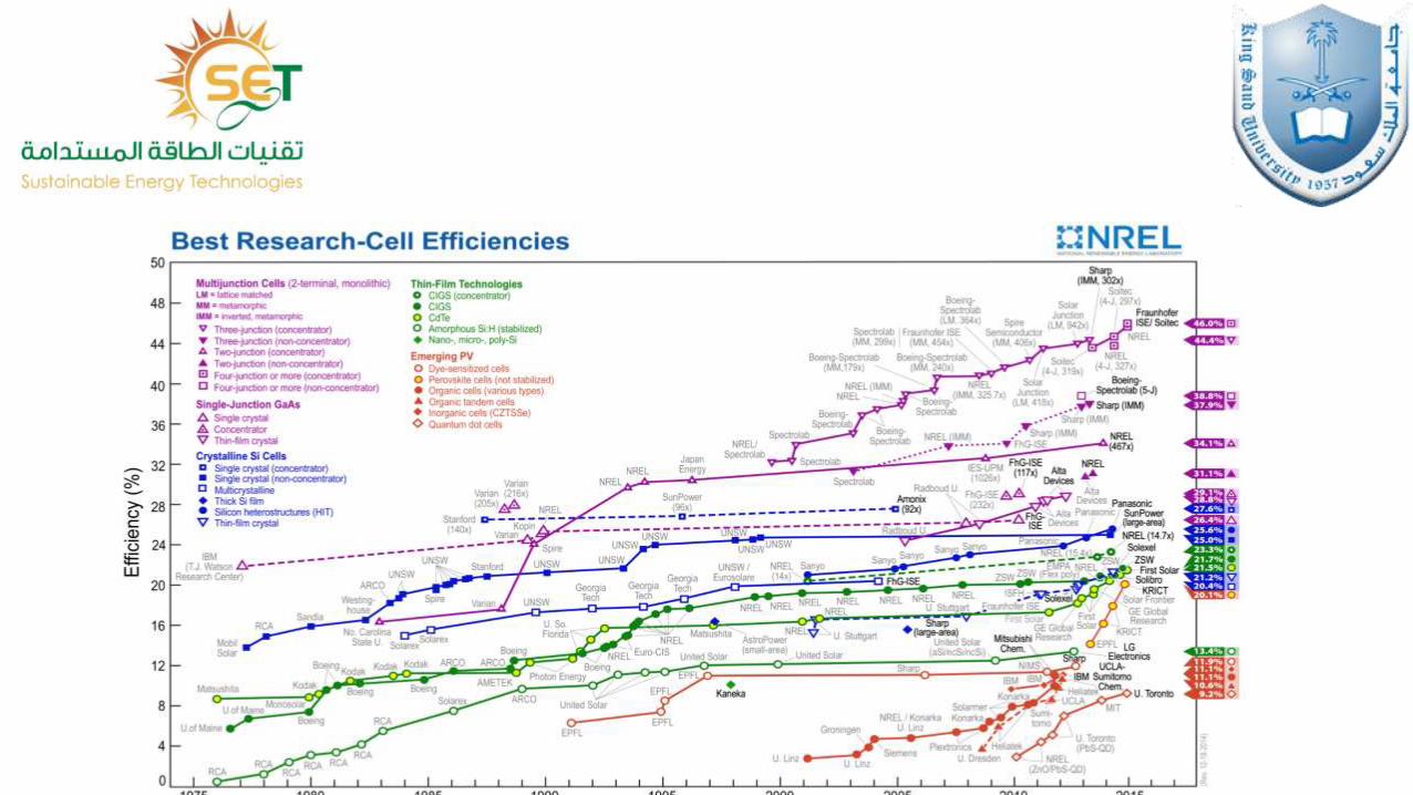
Photovoltaic Cell Types
*Crystalline silicon is the traditional cell material for solar modules,
*thin film technology uses less material and the layers are much thinner compared to mono- and polycrystalline solar cellthus lowering the manufacturing cost.
*Three materials that have been given much attention under thin film technology are amorphous silicon, CdS/CdTe and copper indium selenide CIS ) copper indium diselenide (CIS), and copper indium gallium diselenide (CIGS).
*Polymer materials have many advantages like low cost, lightweight and environmental friendly. The only problem is it has very low efficiency compared to other materials.
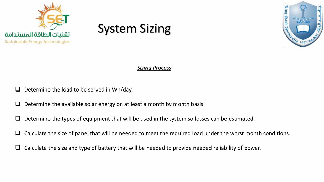
System Sizing
Sizing Process
Determine the load to be served in Wh/day.
Determine the available solar energy on at least a month by month basis.
Determine the types of equipment that will be used in the system so losses can be estimated.
Calculate the size of panel that will be needed to meet the required load under the worst month conditions.
Calculate the size and type of battery that will be needed to provide needed reliability of power.
Thank you