Principles and Applications of Liquid Scintillation Counting · PDF file1 Fundamentals of...
15
Principles and Applications of Liquid Scintillation Counting A PRIMER FOR ORIENTATION – National Diagnostics Laboratory Staff Principles 1.1 RADIOACTIVE EMISSIONS 1.2 MEASUREMENT OF RADIATION AND ISOTOPE QUANTITATION 1.3 MECHANISM OF LIQUID SCINTILLATION COUNTING 1.4 LIQUID SCINTILLATION SIGNAL INTERPRETATION 1.5 THE COMPLETE SCINTILLATION COCKTAIL 1.6 CHEMILUMINESCENCE AND STATIC ELECTRICITY 1.7 WASTE DISPOSAL ISSUES Applications 2.1 COUNTING DISCRETE SAMPLES 2.2 SPECIAL SAMPLE PREPARATION PROTOCOLS 2.3 FLOW LIQUID SCINTILLATION 2.4 LIQUID SCINTILLATION AND RADIATION SAFETY USA: 1-800-526-3867 EUROPE: 441 482 646022 © 2004 National Diagnostics
Transcript of Principles and Applications of Liquid Scintillation Counting · PDF file1 Fundamentals of...
Principles and Applications ofLiquid Scintillation CountingA PRIMER FOR ORIENTATION
– National Diagnostics Laboratory Staff
Principles
1.1 RADIOACTIVE EMISSIONS
1.2 MEASUREMENT OF RADIATION AND ISOTOPE QUANTITATION
1.3 MECHANISM OF LIQUID SCINTILLATION COUNTING
1.4 LIQUID SCINTILLATION SIGNAL INTERPRETATION
1.5 THE COMPLETE SCINTILLATION COCKTAIL
1.6 CHEMILUMINESCENCE AND STATIC ELECTRICITY
1.7 WASTE DISPOSAL ISSUES
Applications
2.1 COUNTING DISCRETE SAMPLES
2.2 SPECIAL SAMPLE PREPARATION PROTOCOLS
2.3 FLOW LIQUID SCINTILLATION
2.4 LIQUID SCINTILLATION AND RADIATION SAFETY
USA: 1-800-526-3867EUROPE: 441 482 646022© 2004 National Diagnostics
USA: 1-800-526-3867EUROPE: 441 482 646022
2
LSC Concepts - Fundamentals of Liquid Scintillation Counting
Liquid Scintillation Counting...Making Light of the Situation
The chemical properties of an element are determined by its atomic number - the number of protons in thenucleus (and electrons within neutral atoms of that element). Uncharged neutrons, within the nucleus alongwith protons, do not contribute to the atomic number, but will alter the atomic mass. This makes possible the
existence of isotopes, which are atoms of the same element with different atomic weight. Most isotopes are stable,and do not undergo any spontaneous nuclear changes. A subset of isotopes possess too few or too many neutrons tobe stable. These are radioactive. Radioactive atoms spontaneously rearrange their nuclei, emitting energy or par-ticles in the process.
Radioactive isotopes of common elements are extremely useful in life science disciplines, among others, becauseradioactive atoms can be substituted for their nonradioactive counterparts in chemical formulations. The resultingradioactive compound is easily detectable but still chemically identical to the original material. Two detectionmethods predominate for assaying such incorporated radioactivity. In autoradiography, labeled material is allowedto expose a photographic emulsion. Development of the emulsion reveals the distribution of labeled material. Inthe second detection method, the amount of radioactivity in labeled samples is directly measured, either by a Geigercounter or by a scintillation counter. In scintillation counting, the sample is mixed with a material that will fluoresceupon interaction with a particle emitted by radioactive decay. The scintillation counter quantifies the resultingflashes of light.
1 Fundamentals of LiquidScintillation Counting
1.1 RADIOACTIVE EMISSIONSTypes of Radioactive Emission / Characteristics ofUseful Isotopes / Use of Isotopes in Research
1.2 MEASUREMENT OF RADIATIONAND ISOTOPE QUANTITATIONIonization Detection / Scintillation Detection
1.3 MECHANISM OF LIQUIDSCINTILLATION COUNTINGThe Role of the Solvent / The Role of Phosphors(Scintillators)
1.4 LIQUID SCINTILLATION SIGNALINTERPRETATIONPatterns of Light Emission / Pulse Analysis /Counting Efficiency / Quenching
1.5 THE COMPLETE SCINTILLATIONCOCKTAIL
1.6 CHEMILUMINESCENCE ANDSTATIC ELECTRICITY
1.7 WASTE DISPOSAL ISSUES
LSC Concepts - Fundamentals of Liquid Scintillation Counting
USA: 1-800-526-3867EUROPE: 441 482 646022
3
1.1 Radioactive Emissions
1.1.1 Types of Radioactive Emission
Radioactive decay occurs with the emission of particles or electromag-netic radiation from an atom due to a change within its nucleus. Formsof radioactive emission include alpha particles (α), beta particles (β),and gamma rays (γ). α particles are the least energetic, most massiveof these decay products. An α particle contains two protons and twoneutrons, and thus comprises a stable helium nucleus. α particles onlyweakly penetrate whatever matter they encounter. They are unable topenetrate even 10 cm of air.
β particles are high energy electrons. These are produced during theconversion of a neutron to a proton in the nucleus. β particles areemitted in concert with a neutrino (Neutrinos are almost impossibleto detect). The sum of the energies of the neutrino and β particle is aconstant for a given isotope, and defines the maximum energy (Emax)which can be observed for any particle emitted from that isotope. Emaxis approached only for particles emitted with a low energy neutrino.In practice a distribution of energies is observed, which is characteris-tic for the emitting isotope.
γ -rays differ from α and β emissions in that γ-rays are electromagneticradiation, not particles. γ -rays are quite penetrating, in many casespassing through up to 5 cm of lead. Additionally, γ -rays are capableof generating secondary β emission from material they pass through.An electron in the material may absorb the energy of the γ-ray, and bepromoted to an excited state which is no longer bound to its nucleus.Such an electron escapes from the atom as a free β-particle.
1.1.2 Characteristics of Useful Isotopes
The list of known radioisotopes is extensive, but the number of iso-topes used in research is fairly small. To be useful as a label in re-search, an isotope must meet a restrictive set of qualifications. First ofall, it must be an element that is already a part of the experimentalsystem. For biological research, for example, isotopes of carbon, hy-drogen, oxygen, and phosphorus are widely used. Alternatively, anelement which can be substituted for another in the system may beused: sulfur isotopes can be used in place of oxygen, for example.
Useful isotopes must also have a reasonable half-life. The half-life ofan isotope is a measure of the rate at which it decays to a nonradioac-tive state. As each nucleus emits its radiation, it eventually reaches astable configuration which will not emit again. Thus a given quantityof isotope will eventually yield a finite total amount of radiation. Eachnucleus decays independently, so the probability of a decay event oc-curring at any time is equal to the probability of any one nucleus de-caying multiplied by the total number of radioactive nuclei present.This number changes as decay progresses, always proportional to thenumber of radioactive nuclei remaining. To express a rate of radioac-tive decay which is independent of the amount of material involved,the time required for the decay of 50% of the starting material, thehalf-life, is a useful quantity. Half-lives may range from millisecondsto thousands of years, a value characteristic of the particular isotope.Assuming that a 24 hour period is required for an experiment, an iso-tope with a half life (t1/2) of 6 hours would undergo 24 fold reductionin emissions, or a loss of 94%. Most experimentally used isotopes havet 1/2 values of 10 days or more.
To determine the number of radioactive at-oms present within a sample at a given time,use the equations above.
λ = decay constantt1/2 = half-lifeN = number of radioactive atomsN0 = initial numbert = elapsed time
Radioisotopes: Decay Products and Energies
Isotope EmissionEnergy(MeV)
Tritium (3H)
Carbon (14C)
Sulfur (35S)
Phosphorus (32P)
Phosphorus (33P)
Iodine (125I)
β
β
β
β
β
γ
Half Life (t1/2)
0.019
0.156
0.167
1.710
0.249
0.178
12.3 yrs
5730 yrs
87.2 days
14.3 days
25.3 days
59.9 days
Table 1.1.2a
1.1.3 The Use of Isotopes in Research
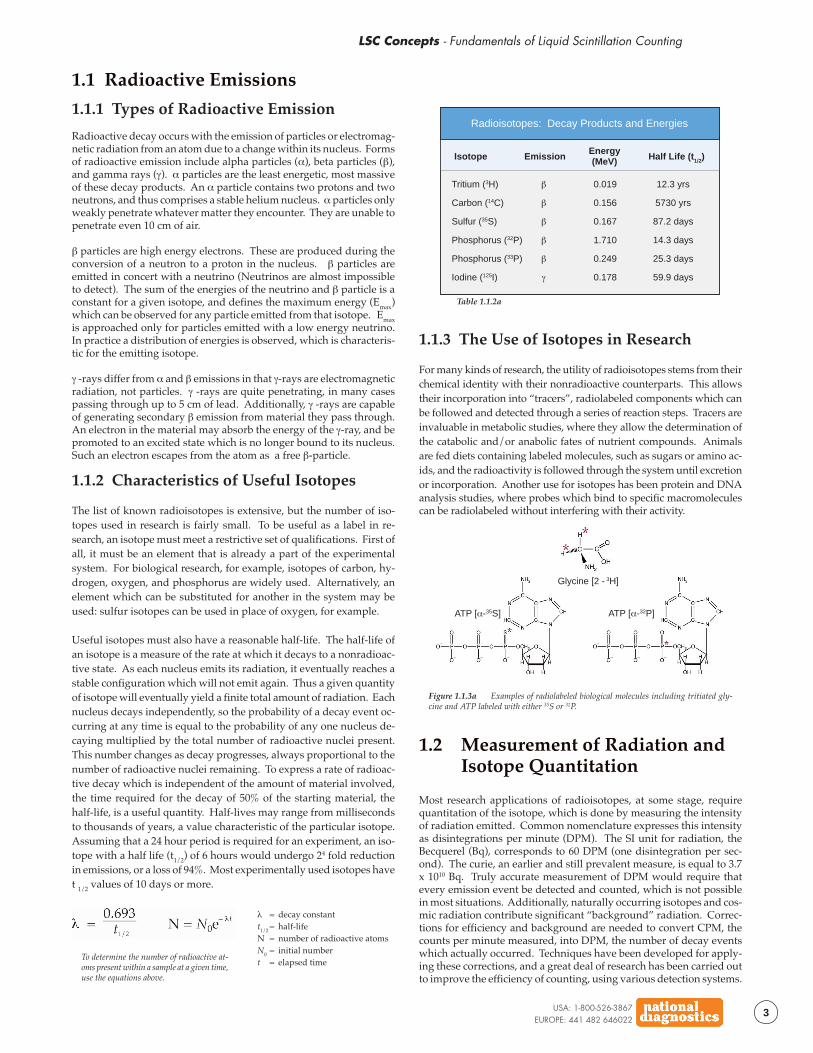
For many kinds of research, the utility of radioisotopes stems from theirchemical identity with their nonradioactive counterparts. This allowstheir incorporation into “tracers”, radiolabeled components which canbe followed and detected through a series of reaction steps. Tracers areinvaluable in metabolic studies, where they allow the determination ofthe catabolic and/or anabolic fates of nutrient compounds. Animalsare fed diets containing labeled molecules, such as sugars or amino ac-ids, and the radioactivity is followed through the system until excretionor incorporation. Another use for isotopes has been protein and DNAanalysis studies, where probes which bind to specific macromoleculescan be radiolabeled without interfering with their activity.
Figure 1.1.3a Examples of radiolabeled biological molecules including tritiated gly-cine and ATP labeled with either 35S or 32P.
ATP [α-35S] ATP [α-32P]
1.2 Measurement of Radiation andIsotope Quantitation
Most research applications of radioisotopes, at some stage, requirequantitation of the isotope, which is done by measuring the intensityof radiation emitted. Common nomenclature expresses this intensityas disintegrations per minute (DPM). The SI unit for radiation, theBecquerel (Bq), corresponds to 60 DPM (one disintegration per sec-ond). The curie, an earlier and still prevalent measure, is equal to 3.7x 10¹⁰ Bq. Truly accurate measurement of DPM would require thatevery emission event be detected and counted, which is not possiblein most situations. Additionally, naturally occurring isotopes and cos-mic radiation contribute significant “background” radiation. Correc-tions for efficiency and background are needed to convert CPM, thecounts per minute measured, into DPM, the number of decay eventswhich actually occurred. Techniques have been developed for apply-ing these corrections, and a great deal of research has been carried outto improve the efficiency of counting, using various detection systems.
Glycine [2 - 3H]
USA: 1-800-526-3867EUROPE: 441 482 646022
4
LSC Concepts - Fundamentals of Liquid Scintillation Counting
Liquid scintillation (LSC), detailed in the next section, was evolved toprovide a usable method for counting organic isotopic compounds.These materials are most often water soluble β-emitters. LSC addressesthe need for convenience, reproducibility, and high sensitivity in theseassays. It also offers solutions to the problem of counting aqueous(i.e. biological) samples in a nonaqueous environment.
1.3 Mechanism of LiquidScintillation Counting
By eliminating the combustion steps needed for gas phase analysis,the introduction of liquid scintillation counting (LSC) reduced the timerequired to analyze radioactive samples from hours to minutes. Forlow energy (“soft”) β emitters, LSC offers unmatched convenience andsensitivity. LSC detects radioactivity via the same type of light emis-sion events which are used in solid scintillation. The key difference isthat in LSC the scintillation takes place in a solution of scintillator,rather than in a solid crystal. This allows close contact between theisotope atoms and the scintillator, which is not possible with solid scin-tillation. With LSC the short path length of soft β emissions is not anobstacle to detection.Liquid scintillation cocktails absorb the energy emitted by radioiso-topes and re-emit it as flashes of light. To accomplish these two ac-tions, absorption and re-emission, cocktails contain two basic compo-nents, the solvent and the phosphor(s). The solvent carries out thebulk of the energy absorption. Dissolved in the solvent, molecules ofphosphor convert the absorbed energy into light. Many cocktails con-tain additional materials to extend their range of use to different samplecompositions, but the solvent and the phosphor provide the scintilla-tion of the mixture.
1.3.1 The Role of the Solvent
The solvent portion of an LSC cocktail comprises from 60 - 99% of thetotal solution. When a radioisotope dissolved in the cocktail undergoesan emission event, it is highly probable that the particle or ray will en-counter only solvent molecules before its energy is spent. For this rea-son, the solvent must act as an efficient collector of energy, and it mustconduct that energy to the phosphor molecules instead of dissipatingthe energy by some other mechanism. The solvent must not quench thescintillation of the phosphor, and, finally, the solvent must dissolve thephosphor to produce a stable, countable solution.
Aromatic organics have proven to be the best solvents for LSC. Theprototypical LSC solvent is toluene (The solvents used in NationalDiagnostics scintillation fluids are safer and less toxic than toluene).The π cloud of the toluene ring (or any aromatic ring) provides a tar-get for β-interaction, which captures the energy of the incident par-ticle. This captured energy is generally lost through transfer to an-other solvent molecule, as toluene has little tendency to emit light orundergo other alternate decay modes. Thus, a β-particle passingthrough a toluene solution leaves in its wake a number of energizedtoluene molecules. The energy from these molecules passes back andforth among the solvent ring systems, allowing efficient capture bydissolved phosphors.
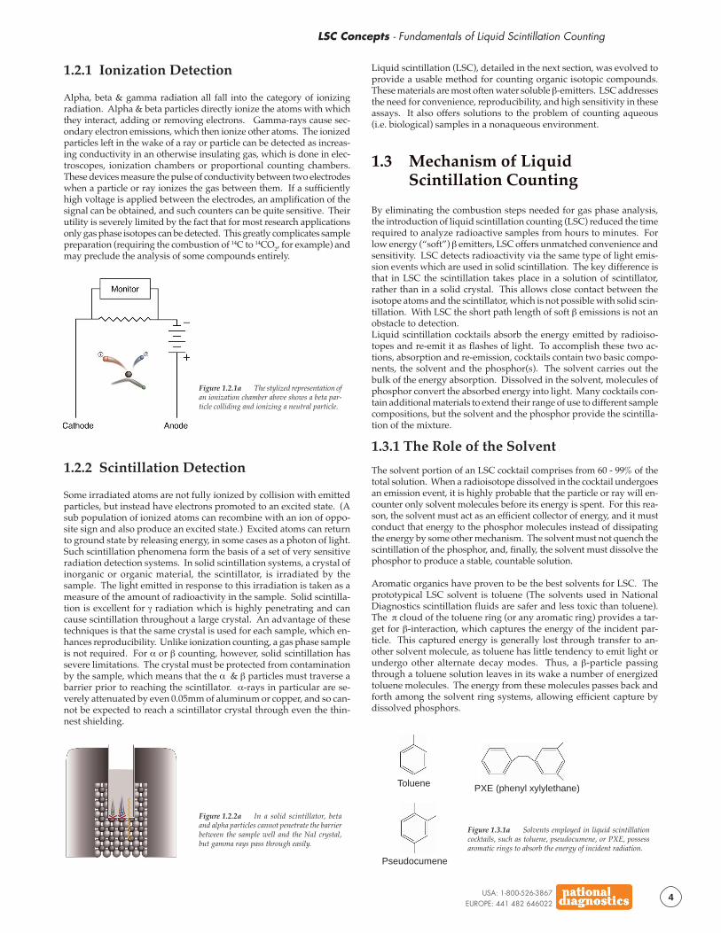
Figure 1.2.2a In a solid scintillator, betaand alpha particles cannot penetrate the barrierbetween the sample well and the NaI crystal,but gamma rays pass through easily.
1.2.1 Ionization Detection
Alpha, beta & gamma radiation all fall into the category of ionizingradiation. Alpha & beta particles directly ionize the atoms with whichthey interact, adding or removing electrons. Gamma-rays cause sec-ondary electron emissions, which then ionize other atoms. The ionizedparticles left in the wake of a ray or particle can be detected as increas-ing conductivity in an otherwise insulating gas, which is done in elec-troscopes, ionization chambers or proportional counting chambers.These devices measure the pulse of conductivity between two electrodeswhen a particle or ray ionizes the gas between them. If a sufficientlyhigh voltage is applied between the electrodes, an amplification of thesignal can be obtained, and such counters can be quite sensitive. Theirutility is severely limited by the fact that for most research applicationsonly gas phase isotopes can be detected. This greatly complicates samplepreparation (requiring the combustion of 14C to 14CO2, for example) andmay preclude the analysis of some compounds entirely.
Figure 1.2.1a The stylized representation ofan ionization chamber above shows a beta par-ticle colliding and ionizing a neutral particle.
Figure 1.3.1a Solvents employed in liquid scintillationcocktails, such as toluene, pseudocumene, or PXE, possessaromatic rings to absorb the energy of incident radiation.
1.2.2 Scintillation Detection
Some irradiated atoms are not fully ionized by collision with emittedparticles, but instead have electrons promoted to an excited state. (Asub population of ionized atoms can recombine with an ion of oppo-site sign and also produce an excited state.) Excited atoms can returnto ground state by releasing energy, in some cases as a photon of light.Such scintillation phenomena form the basis of a set of very sensitiveradiation detection systems. In solid scintillation systems, a crystal ofinorganic or organic material, the scintillator, is irradiated by thesample. The light emitted in response to this irradiation is taken as ameasure of the amount of radioactivity in the sample. Solid scintilla-tion is excellent for γ radiation which is highly penetrating and cancause scintillation throughout a large crystal. An advantage of thesetechniques is that the same crystal is used for each sample, which en-hances reproducibility. Unlike ionization counting, a gas phase sampleis not required. For α or β counting, however, solid scintillation hassevere limitations. The crystal must be protected from contaminationby the sample, which means that the α & β particles must traverse abarrier prior to reaching the scintillator. α-rays in particular are se-verely attenuated by even 0.05mm of aluminum or copper, and so can-not be expected to reach a scintillator crystal through even the thin-nest shielding.
PXE (phenyl xylylethane)Toluene
Pseudocumene
LSC Concepts - Fundamentals of Liquid Scintillation Counting
USA: 1-800-526-3867EUROPE: 441 482 646022
5
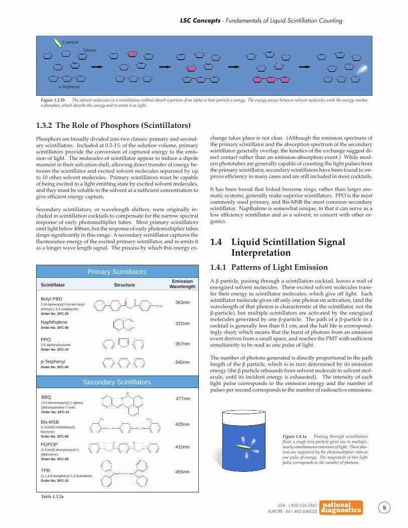
1.3.2 The Role of Phosphors (Scintillators)
Phosphors are broadly divided into two classes: primary and second-ary scintillators. Included at 0.3-1% of the solution volume, primaryscintillators provide the conversion of captured energy to the emis-sion of light. The molecules of scintillator appear to induce a dipolemoment in their solvation shell, allowing direct transfer of energy be-tween the scintillator and excited solvent molecules separated by upto 10 other solvent molecules. Primary scintillators must be capableof being excited to a light emitting state by excited solvent molecules,and they must be soluble in the solvent at a sufficient concentration togive efficient energy capture.
Secondary scintillators, or wavelength shifters, were originally in-cluded in scintillation cocktails to compensate for the narrow spectralresponse of early photomultiplier tubes. Most primary scintillatorsemit light below 408nm, but the response of early photomultiplier tubesdrops significantly in this range. A secondary scintillator captures thefluorescence energy of the excited primary scintillator, and re-emits itas a longer wave length signal. The process by which this energy ex-
Figure 1.3.1b The solvent molecules in a scintillation cocktail absorb a portion of an alpha or beta particle’s energy. The energy passes between solvent molecules until the energy reachesa phosphor, which absorbs the energy and re-emits it as light.
Toluene
p-Terphenyl
β particle
change takes place is not clear. (Although the emission spectrum ofthe primary scintillator and the absorption spectrum of the secondaryscintillator generally overlap, the kinetics of the exchange suggest di-rect contact rather than an emission-absorption event.) While mod-ern phototubes are generally capable of counting the light pulses fromthe primary scintillator, secondary scintillators have been found to im-prove efficiency in many cases and are still included in most cocktails.
It has been found that linked benzene rings, rather than larger aro-matic systems, generally make superior scintillators. PPO is the mostcommonly used primary, and Bis-MSB the most common secondaryscintillator. Napthalene is somewhat unique, in that it can serve as alow efficiency scintillator and as a solvent, in concert with other or-ganics.
1.4 Liquid Scintillation SignalInterpretation
1.4.1 Patterns of Light Emission
A β particle, passing through a scintillation cocktail, leaves a trail ofenergized solvent molecules. These excited solvent molecules trans-fer their energy to scintillator molecules, which give off light. Eachscintillator molecule gives off only one photon on activation, (and thewavelength of that photon is characteristic of the scintillator, not theβ-particle), but multiple scintillators are activated by the energizedmolecules generated by one β-particle. The path of a β-particle in acocktail is generally less than 0.1 cm; and the half life is correspond-ingly short, which means that the burst of photons from an emissionevent derives from a small space, and reaches the PMT with sufficientsimultaneity to be read as one pulse of light.
The number of photons generated is directly proportional to the pathlength of the β particle, which is in turn determined by its emissionenergy (the β particle rebounds from solvent molecule to solvent mol-ecule, until its incident energy is exhausted). The intensity of eachlight pulse corresponds to the emission energy and the number ofpulses per second corresponds to the number of radioactive emissions.
Scintillator StructureEmission
Wavelength
Butyl PBD2-[4-biphenylyl]-5-[4-tert-butyl-phenyl]-1,3,4-oxadiazole)Order No. SFC-20
NaphthaleneOrder No. SFC-40
p-TerphenylOrder No. SFC-50
363nm
322nm
340nm
Primary Scintillators
Secondary Scintillators
TPB(1,1,4,4-tetraphenyl-1,3-butadiene)Order No. SFC-15
455nm
Table 1.3.2a
PPO2,5-diphenyloxazoleOrder No. SFC-10
357nm
BBQ(7H-benzimidazo[2,1-a]benz[de]isoquinoline-7-one)Order No. SFC-13
477nm
POPOP(1,4-bis[5-phenyloxazol-2-yl]benzene)Order No. SFC-60
410nm
Bis-MSB(1,4-bis[2-methylstyryl]-benzene)Order No. SFC-90
420nm
Figure 1.4.1a Passing through scintillationfluid, a single beta particle gives rise to multiple,nearly simultaneous emissions of light. These pho-tons are registered by the photomultiplier tube asone pulse of energy. The magnitude of this lightpulse corresponds to the number of photons.
USA: 1-800-526-3867EUROPE: 441 482 646022
6
LSC Concepts - Fundamentals of Liquid Scintillation Counting
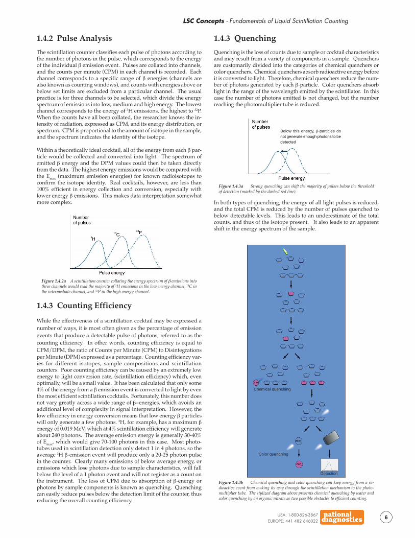
1.4.2 Pulse Analysis
The scintillation counter classifies each pulse of photons according tothe number of photons in the pulse, which corresponds to the energyof the individual β emission event. Pulses are collated into channels,and the counts per minute (CPM) in each channel is recorded. Eachchannel corresponds to a specific range of β energies (channels arealso known as counting windows), and counts with energies above orbelow set limits are excluded from a particular channel. The usualpractice is for three channels to be selected, which divide the energyspectrum of emissions into low, medium and high energy. The lowestchannel corresponds to the energy of 3H emissions, the highest to 32P.When the counts have all been collated, the researcher knows the in-tensity of radiation, expressed as CPM, and its energy distribution, orspectrum. CPM is proportional to the amount of isotope in the sample,and the spectrum indicates the identity of the isotope.
Within a theoretically ideal cocktail, all of the energy from each β par-ticle would be collected and converted into light. The spectrum ofemitted β energy and the DPM values could then be taken directlyfrom the data. The highest energy emissions would be compared withthe Emax (maximum emission energies) for known radioisotopes toconfirm the isotope identity. Real cocktails, however, are less than100% efficient in energy collection and conversion, especially withlower energy β emissions. This makes data interpretation somewhatmore complex.
Figure 1.4.2a A scintillation counter collating the energy spectrum of β emissions intothree channels would read the majority of 3H emissions in the low energy channel, 14C inthe intermediate channel, and 32P in the high energy channel.
1.4.3 Counting Efficiency
While the effectiveness of a scintillation cocktail may be expressed anumber of ways, it is most often given as the percentage of emissionevents that produce a detectable pulse of photons, referred to as thecounting efficiency. In other words, counting efficiency is equal toCPM/DPM, the ratio of Counts per Minute (CPM) to Disintegrationsper Minute (DPM) expressed as a percentage. Counting efficiency var-ies for different isotopes, sample compositions and scintillationcounters. Poor counting efficiency can be caused by an extremely lowenergy to light conversion rate, (scintillation efficiency) which, evenoptimally, will be a small value. It has been calculated that only some4% of the energy from a β emission event is converted to light by eventhe most efficient scintillation cocktails. Fortunately, this number doesnot vary greatly across a wide range of β−energies, which avoids anadditional level of complexity in signal interpretation. However, thelow efficiency in energy conversion means that low energy β particleswill only generate a few photons. 3H, for example, has a maximum βenergy of 0.019 MeV, which at 4% scintillation efficiency will generateabout 240 photons. The average emission energy is generally 30-40%of Emax, which would give 70-100 photons in this case. Most photo-tubes used in scintillation detection only detect 1 in 4 photons, so theaverage 3H β-emission event will produce only a 20-25 photon pulsein the counter. Clearly many emissions of below average energy, oremissions which lose photons due to sample characteristics, will fallbelow the level of a 1 photon event and will not register as a count onthe instrument. The loss of CPM due to absorption of β-energy orphotons by sample components is known as quenching. Quenchingcan easily reduce pulses below the detection limit of the counter, thusreducing the overall counting efficiency.
1.4.3 Quenching
Quenching is the loss of counts due to sample or cocktail characteristicsand may result from a variety of components in a sample. Quenchersare customarily divided into the categories of chemical quenchers orcolor quenchers. Chemical quenchers absorb radioactive energy beforeit is converted to light. Therefore, chemical quenchers reduce the num-ber of photons generated by each β-particle. Color quenchers absorblight in the range of the wavelength emitted by the scintillator. In thiscase the number of photons emitted is not changed, but the numberreaching the photomultiplier tube is reduced.
Figure 1.4.3a Strong quenching can shift the majority of pulses below the thresholdof detection (marked by the dashed red line).
Below this energy, β-particles donot generate enough photons to bedetected
In both types of quenching, the energy of all light pulses is reduced,and the total CPM is reduced by the number of pulses quenched tobelow detectable levels. This leads to an underestimate of the totalcounts, and thus of the isotope present. It also leads to an apparentshift in the energy spectrum of the sample.
Figure 1.4.3b Chemical quenching and color quenching can keep energy from a ra-dioactive event from making its way through the scintillation mechanism to the photo-multiplier tube. The stylized diagram above presents chemical quenching by water andcolor quenching by an organic nitrate as two possible obstacles to efficient counting.
Chemical quenching
Color quenching
Detection
LSC Concepts - Fundamentals of Liquid Scintillation Counting
USA: 1-800-526-3867EUROPE: 441 482 646022
7
Quench CorrectionVarious methods are available for quench correction. The most straight-forward, but most laborious, is the use of an internal standard. A knownamount of radioactivity, added to an unknown sample, will increase theDPM by a predictable amount. The difference between the increase inDPM observed and that expected is due to quenching, and allows thedetermination of counting efficiency for that sample. The drawback tothe use of internal standards is that each sample must be counted twice.It is also inconvenient to add an internal standard to many vials.
Many scintillation counters offer the use of an external standard to cor-rect for quenching. After initial counting, a strong γ emission source isplaced next to the vial and the sample is counted again. The γ rayscause secondary emission of Compton electrons, which scintillate in thecocktail like β particles. The counts due to sample radioactivity are sub-tracted, leaving only the Compton electron counts. The theoretical en-ergy distribution of the Compton electrons is compared with the mea-sured energy spectrum to determine the extent of quenching. Thesamples must still be counted twice, but nothing need be added to thevials, and the process may be carried out automatically by the counter.
The analysis of the energy spectrum is commonly done by computinga “channels ratio”. The detected counts are divided into channels basedon their relative energies, and the number of high energy counts (withtwo channels, the “B” channel) is compared to the number of low en-ergy counts (channel “A”). The ratio, calculated as B/A or B/B+A,will change if the sample is quenched. Quenching reduces the inten-sity of each light pulse, so counts will appear to be of lower energy.This will shift counts from high to low energy channels, and decreasethe channels ratio. In practice, a set of quenched standards is createdby adding a quenching agent to reduce the CPM of an internal stan-dard. The channels ratio of the external standard is then determined,and a correlation is established between quench and channels ratio.The channels ratio analysis may also be applied to the sample itself todetermine quenching. Again, a set of quenched standards is assembled,and a known amount of radioactivity is added to each. A curve isconstructed, relating CPM/DPM to B/B+A. Once this curve has beengenerated, the quench of any subsequent sample can be determinedfrom its channels ratio. This quenching factor is then used to correctCPM to DPM.
1.5 The Complete ScintillationCocktail
Living creatures contain both hydrophobic and hydrophilic com-pounds, any of which may be labeled during the course of a radioac-tive experiment. As discussed in earlier sections, the best solvents forscintillation counting are the aromatic organics, such as toluene andxylene. Hydrophobic compounds can be counted directly in such sol-vents, but hydrophilic materials, which include many biologicalsamples, are completely insoluble in simple cocktails. This requiresthe engineering of complex cocktails, capable of bringing hydrophilicsample molecules into close proximity to organic solvents and the dis-solved scintillators.
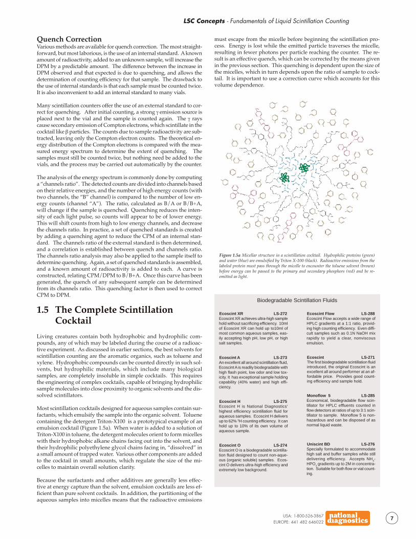
Most scintillation cocktails designed for aqueous samples contain sur-factants, which emulsify the sample into the organic solvent. Toluenecontaining the detergent Triton-X100 is a prototypical example of anemulsion cocktail (Figure 1.5a). When water is added to a solution ofTriton-X100 in toluene, the detergent molecules orient to form micelleswith their hydrophobic alkane chains facing out into the solvent, andtheir hydrophilic polyethylene glycol chains facing in, “dissolved” ina small amount of trapped water. Various other components are addedto the cocktail in small amounts, which regulate the size of the mi-celles to maintain overall solution clarity.
Because the surfactants and other additives are generally less effec-tive at energy capture than the solvent, emulsion cocktails are less ef-ficient than pure solvent cocktails. In addition, the partitioning of theaqueous samples into micelles means that the radioactive emissions
must escape from the micelle before beginning the scintillation pro-cess. Energy is lost while the emitted particle traverses the micelle,resulting in fewer photons per particle reaching the counter. The re-sult is an effective quench, which can be corrected by the means givenin the previous section. This quenching is dependent upon the size ofthe micelles, which in turn depends upon the ratio of sample to cock-tail. It is important to use a correction curve which accounts for thisvolume dependence.
Figure 1.5a Micellar structure in a scintillation cocktail. Hydrophilic proteins (green)and water (blue) are emulsified by Triton X-100 (black). Radioactive emissions from thelabeled protein must pass through the micelle to encounter the toluene solvent (brown)before energy can be passed to the primary and secondary phosphors (red) and be re-emitted as light.
Ecoscint XR LS-272Ecoscint XR achieves ultra-high samplehold without sacrificing efficiency. 10mlof Ecoscint XR can hold up to10ml ofmost common aqueous samples, eas-ily accepting high pH, low pH, or highsalt samples.
Ecoscint A LS-273An excellent all around scintillation fluid,Ecoscint A is readily biodegradable withhigh flash point, low odor and low tox-icity. It has exceptional sample holdingcapability (40% water) and high effi-ciency.
Ecoscint H LS-275Ecoscint H is National Diagnostics’highest efficiency scintillation fluid foraqueous samples. Ecoscint H deliversup to 62% 3H counting efficiency. It canhold up to 10% of its own volume ofaqueous sample.
Ecoscint O LS-274Ecoscint O is a biodegradable scintilla-tion fluid designed to count non-aque-ous (organic soluble) samples. Ecos-cint O delivers ultra-high efficiency andextremely low background.
Biodegradable Scintillation Fluids
Ecoscint Flow LS-288Ecoscint Flow accepts a wide range ofHPLC gradients at a 1:1 ratio, provid-ing high counting efficiency. Even diffi-cult samples such as 0.1N NaOH mixrapidly to yield a clear, nonviscousemulsion.
Ecoscint LS-271The first biodegradable scintillation fluidintroduced, the original Ecoscint is anexcellent all around performer at an af-fordable price. Provides good count-ing efficiency and sample hold.
Monoflow 5 LS-285Economical, biodegradable flow scin-tillator for HPLC effluents counted inflow detectors at ratios of up to 3:1 scin-tillator to sample. Monoflow 5 is non-hazardous and can be disposed of asnormal liquid waste.
Uniscint BD LS-276Specially formulated to accommodatehigh salt and buffer samples while stilldelivering efficiency. Accepts NH
4-
HPO3 gradients up to 2M in concentra-
tion. Suitable for both flow or vial count-ing.
USA: 1-800-526-3867EUROPE: 441 482 646022
8
LSC Concepts - Fundamentals of Liquid Scintillation Counting
Sample Holding Capacities of NationalDiagnostics Ecoscint A
SampleCapacity
(ml sample /10ml cocktail)
Water (20°C)
Water (25°C)
Water (15°C)
0.05M Tris-HCl
0.15M NaCl
10% Sucrose
8M Urea
4.5
4.0
5.0
4.5
4.0
3.0
1.0
Table 1.5a
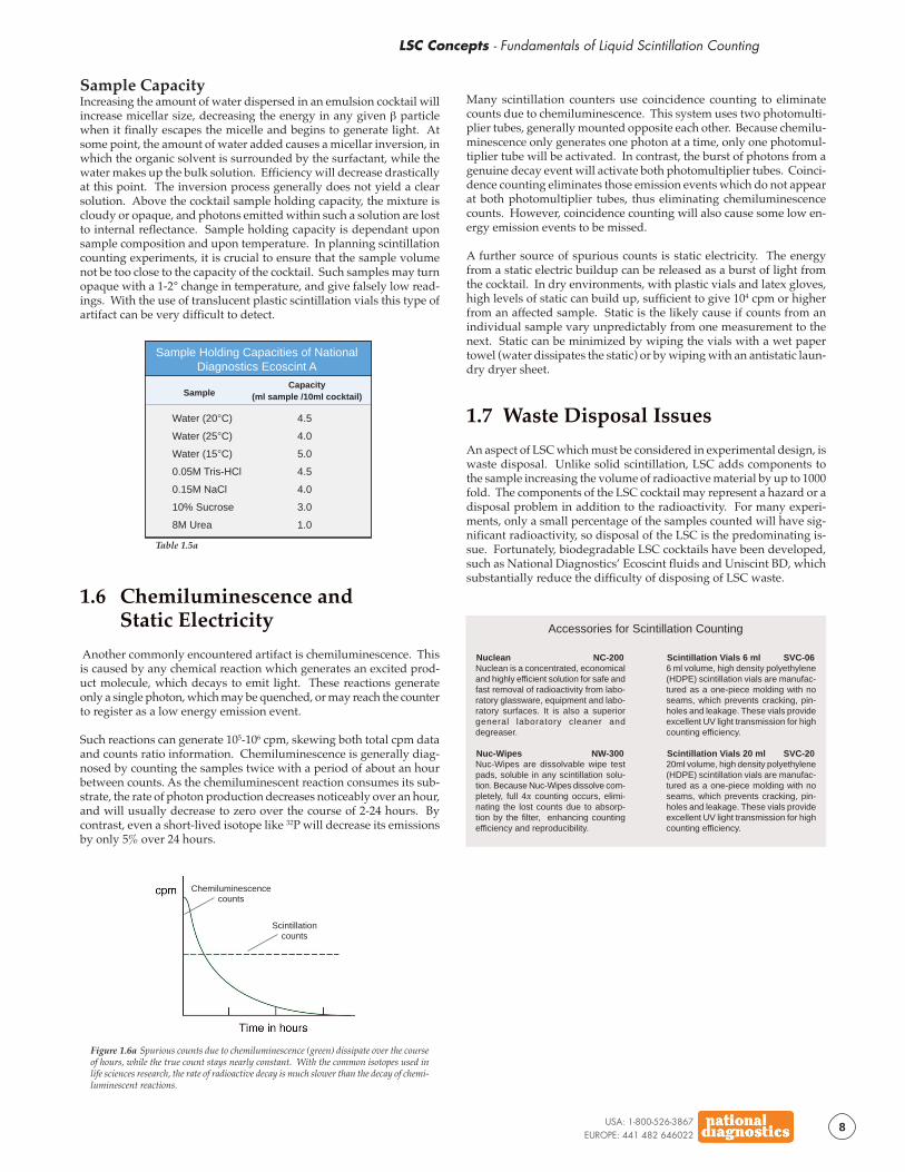
Figure 1.6a Spurious counts due to chemiluminescence (green) dissipate over the courseof hours, while the true count stays nearly constant. With the common isotopes used inlife sciences research, the rate of radioactive decay is much slower than the decay of chemi-luminescent reactions.
Scintillationcounts
Chemiluminescencecounts
Sample CapacityIncreasing the amount of water dispersed in an emulsion cocktail willincrease micellar size, decreasing the energy in any given β particlewhen it finally escapes the micelle and begins to generate light. Atsome point, the amount of water added causes a micellar inversion, inwhich the organic solvent is surrounded by the surfactant, while thewater makes up the bulk solution. Efficiency will decrease drasticallyat this point. The inversion process generally does not yield a clearsolution. Above the cocktail sample holding capacity, the mixture iscloudy or opaque, and photons emitted within such a solution are lostto internal reflectance. Sample holding capacity is dependant uponsample composition and upon temperature. In planning scintillationcounting experiments, it is crucial to ensure that the sample volumenot be too close to the capacity of the cocktail. Such samples may turnopaque with a 1-2° change in temperature, and give falsely low read-ings. With the use of translucent plastic scintillation vials this type ofartifact can be very difficult to detect.
1.6 Chemiluminescence andStatic Electricity
Another commonly encountered artifact is chemiluminescence. Thisis caused by any chemical reaction which generates an excited prod-uct molecule, which decays to emit light. These reactions generateonly a single photon, which may be quenched, or may reach the counterto register as a low energy emission event.
Such reactions can generate 105-106 cpm, skewing both total cpm dataand counts ratio information. Chemiluminescence is generally diag-nosed by counting the samples twice with a period of about an hourbetween counts. As the chemiluminescent reaction consumes its sub-strate, the rate of photon production decreases noticeably over an hour,and will usually decrease to zero over the course of 2-24 hours. Bycontrast, even a short-lived isotope like 32P will decrease its emissionsby only 5% over 24 hours.
Many scintillation counters use coincidence counting to eliminatecounts due to chemiluminescence. This system uses two photomulti-plier tubes, generally mounted opposite each other. Because chemilu-minescence only generates one photon at a time, only one photomul-tiplier tube will be activated. In contrast, the burst of photons from agenuine decay event will activate both photomultiplier tubes. Coinci-dence counting eliminates those emission events which do not appearat both photomultiplier tubes, thus eliminating chemiluminescencecounts. However, coincidence counting will also cause some low en-ergy emission events to be missed.
A further source of spurious counts is static electricity. The energyfrom a static electric buildup can be released as a burst of light fromthe cocktail. In dry environments, with plastic vials and latex gloves,high levels of static can build up, sufficient to give 104 cpm or higherfrom an affected sample. Static is the likely cause if counts from anindividual sample vary unpredictably from one measurement to thenext. Static can be minimized by wiping the vials with a wet papertowel (water dissipates the static) or by wiping with an antistatic laun-dry dryer sheet.
1.7 Waste Disposal Issues
An aspect of LSC which must be considered in experimental design, iswaste disposal. Unlike solid scintillation, LSC adds components tothe sample increasing the volume of radioactive material by up to 1000fold. The components of the LSC cocktail may represent a hazard or adisposal problem in addition to the radioactivity. For many experi-ments, only a small percentage of the samples counted will have sig-nificant radioactivity, so disposal of the LSC is the predominating is-sue. Fortunately, biodegradable LSC cocktails have been developed,such as National Diagnostics’ Ecoscint fluids and Uniscint BD, whichsubstantially reduce the difficulty of disposing of LSC waste.
Nuclean NC-200Nuclean is a concentrated, economicaland highly efficient solution for safe andfast removal of radioactivity from labo-ratory glassware, equipment and labo-ratory surfaces. It is also a superiorgeneral laboratory cleaner anddegreaser.
Nuc-Wipes NW-300Nuc-Wipes are dissolvable wipe testpads, soluble in any scintillation solu-tion. Because Nuc-Wipes dissolve com-pletely, full 4π counting occurs, elimi-nating the lost counts due to absorp-tion by the filter, enhancing countingefficiency and reproducibility.
Accessories for Scintillation Counting
Scintillation Vials 6 ml SVC-066 ml volume, high density polyethylene(HDPE) scintillation vials are manufac-tured as a one-piece molding with noseams, which prevents cracking, pin-holes and leakage. These vials provideexcellent UV light transmission for highcounting efficiency.
Scintillation Vials 20 ml SVC-2020ml volume, high density polyethylene(HDPE) scintillation vials are manufac-tured as a one-piece molding with noseams, which prevents cracking, pin-holes and leakage. These vials provideexcellent UV light transmission for highcounting efficiency.
LSC Concepts - Applications of Liquid Scintillation Counting
USA: 1-800-526-3867EUROPE: 441 482 646022
9
2 Applications of LiquidScintillation Counting
2.1 COUNTING DISCRETE SAMPLESSample Neutralization (Elimination ofChemiluminescence) / Decolorizing
2.2 SPECIAL SAMPLE PREPARATIONPROTOCOLSTLC Plates / Counting Samples on Cellulose-esterFilters (MilliporeTM filters) / Counting TissueSamples / Counting 14CO2 / Samples inPolyacrylamide Gels
2.3 FLOW LIQUID SCINTILLATION
2.4 LIQUID SCINTILLATION ANDRADIATION SAFETY
LSC Applications...Make the Prize Light! - William Shakespeare, The Tempest
Like solid scintillation, liquid scintillation counting was originally applied only to discrete samples, eitheraqueous or nonaqueous, and protocols were developed for each type. The introduction of flow countingapparatus made it possible to use LSC to monitor the effluent from a chromatography column for radioactive
peaks. Again, the samples in flow LSC experiments are divided between aqueous and nonaqueous compositions.
Cocktails have been developed for discrete samples and for flow applications, answering the specific needs of eachtype of experiment. In addition, cocktails are available for a variety of specific applications for the counting ofdiscrete samples with unique characteristics. Most of these cocktails are designed to simplify sample preparation insuch applications as counting samples in electrophoresis gels, samples on filters, whole tissue samples or com-busted materials.
USA: 1-800-526-3867EUROPE: 441 482 646022
10
LSC Concepts - Fundamentals of Liquid Scintillation Counting
2.1 Counting Discrete Samples
Liquid scintillation counting of discrete samples is conceptuallystraightforward. A sample is mixed with an appropriate volume ofscintillation cocktail, and the mixture is placed in an LSC vial andcounted. For some samples, no additional steps are required, but inmany situations, samples must be processed to avoid artifacts. Themost common causes of artifacts are static electricity counts, chemilu-minescent counts and color quenching. Protocols for sample prepara-tion to maximize the efficiency of counting and minimize backgroundare given below. These protocols can be readily adapted to a varietyof samples. Following this section, the preparation and counting ofseveral unique sample types are presented, as “special applications”.
The best counting efficiencies are achieved when samples uniformlydisperse into the cocktail to produce a clear, colorless, pH neutral emul-sion. Uniform dispersion of the sample is achieved by selecting theappropriate cocktail formulation. Organic samples present no prob-lem. With organic samples, the highest efficiency can be achieved incocktails which contain no emulsifiers and which are only suitable fororganics. Organic samples, however, can be successfully counted inemulsifying cocktails, and often the convenience of using one cocktailfor all applications outweighs any loss in efficiency. Aqueous samplespresent more of a challenge. The choice of cocktail will depend uponthe balancing of sample holding and efficiency. It is a good idea tochoose a cocktail which can hold at least 10% more sample than youintend to add, as sample capacity may be strongly affected by tem-perature or sample components.
hours, or in some cases, overnight, before counting. This allows timefor the chemiluminescent reaction to run its course and die out. Ifchemiluminescence is suspected, samples should be counted repeat-edly at intervals of greater than 1 hour until a stable reading is ob-tained.
2.1.2 Decolorizing
Achieving a colorless solution of sample in cocktail is generally notproblematic. Many samples are colorless, or contain so little color thatdilution into the scintillation cocktail gives an essentially colorless so-lution. In those cases where samples are deeply colored, particularlywhen the sample absorbs in the region of 300-400 nm, where scintilla-tion phosphors emit, several decolorizing protocols are available. Asvisible color often depends upon long conjugated polyene systems,strong oxidants are used to “bleach” the samples. Samples can betreated quite harshly prior to counting, because chemical changes tothe labeled compounds will not alter the number of DPM emitted.
Protocol 2.1.2a
Decolorizing LSC Samples with Ultraviolet Light
Ultraviolet irradiation is often effective in bleaching visibly colored samples.The optimal wavelength, intensity and time must of course be determinedfor each sample. In many cases, exposing samples to sunlight for 1-2 hoursis sufficient. Bleaching by UV has a great advantage over other methods -nothing is added to the sample, avoiding the potential quenching or chemi-luminescent effects of other bleaching agents.
Protocol 2.1.2b
Decolorizing LSC Samples with Hydrogen Peroxide
H2O2 is a strong oxidant and a very effective bleaching agent. It is inexpen-sive, easy to work with, and miscible with aqueous samples. The only dis-advantage to using H2O2 is that it decomposes to produce molecular oxy-gen, which is an effective quenching agent. Samples must be heated todrive off the O2 following H2O2 bleaching, to ensure reproducible results.
1. Mix: 0.1 - 0.3 ml of 30% H2O2 with 1ml sample
2. Incubate 1 hour at 50°C, shake occasionally.
3. Cool to room temperature, add scintillation cocktail and count.
Protocol 2.1.2c
Decolorizing LSC Samples with Benzoyl Peroxide
Samples which are not soluble in water or tissues which have been dis-solved in organic solubilizers, can be bleached with Benzoyl Peroxide.
1. Dissolve 1g Benzoyl Peroxide in 5 ml Toluene - heating to 60°C may berequired. Filter solution if cloudy. (Caution: Toluene has a flash point of7°C. Heating must be carried out in a spark-free fume hood to avoidan explosion hazard.)
2. Add 2 ml Benzoyl Peroxide/Toluene solution to 1 ml sample.
3. Incubate for 30 minutes at 50°C.
4. Cool to room temperature, add scintillation cocktail and count.
2.2 Special Sample Preparation
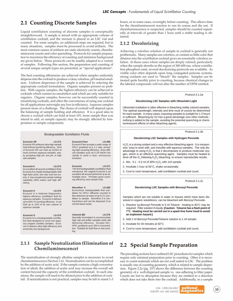
The preceding sections have outlined LSC procedures for samples whichrequire only minimal preparation prior to counting. Often it is neces-sary to count materials which are not well suited to LSC. The problemis usually one of counting geometry, which is related to sample disper-sion. Figure 2.2a (pg. 157) shows the difference between the countinggeometry of a well-dispersed sample vs. one adhering to filter paper.Counts are lost to absorption because they are emitted in a directionwhich does not take them into the cocktail. Additionally, in a sample
Ecoscint XR LS-272Ecoscint XR achieves ultra-high samplehold without sacrificing efficiency. 10mlof Ecoscint XR can hold up to10ml ofmost common aqueous samples, eas-ily accepting high pH, low pH, or highsalt samples.
Ecoscint A LS-273An excellent all around scintillation fluid,Ecoscint A is readily biodegradable withhigh flash point, low odor and low tox-icity. It has exceptional sample holdingcapability (40% water) and high effi-ciency.
Ecoscint H LS-275Ecoscint H is National Diagnostics’highest efficiency scintillation fluid foraqueous samples. Ecoscint H deliversup to 62% 3H counting efficiency. It canhold up to 10% of its own volume ofaqueous sample.
Ecoscint O LS-274Ecoscint O is a biodegradable scintilla-tion fluid designed to count non-aque-ous (organic soluble) samples. Ecos-cint O delivers ultra-high efficiency andextremely low background.
Biodegradable Scintillation Fluids
Ecoscint Flow LS-288Ecoscint Flow accepts a wide range ofHPLC gradients at a 1:1 ratio, provid-ing high counting efficiency. Even diffi-cult samples such as 0.1N NaOH mixrapidly to yield a clear, nonviscousemulsion.
Ecoscint LS-271The first biodegradable scintillation fluidintroduced, the original Ecoscint is anexcellent all around performer at an af-fordable price. Provides good count-ing efficiency and sample hold.
Monoflow 5 LS-285Economical, biodegradable flow scin-tillator for HPLC effluents counted inflow detectors at ratios of up to 3:1 scin-tillator to sample. Monoflow 5 is non-hazardous and can be disposed of asnormal liquid waste.
Uniscint BD LS-276Specially formulated to accommodatehigh salt and buffer samples while stilldelivering efficiency. Accepts NH4-HPO3 gradients up to 2M in concentra-tion. Suitable for both flow or vial count-ing.
2.1.1 Sample Neutralization (Elimination ofChemiluminescence)
The neutralization of strongly alkaline samples is necessary to avoidchemiluminescence (Section 1.6). Neutralization can be accomplishedby the addition of acetic acid. If the sample contains a high concentra-tion of alkali, the addition of acetic acid may increase the overall saltcontent beyond the capacity of the scintillation cocktail. In such situ-ations, the sample will need to be diluted prior to the addition of cock-tail. If neutralization is not practical, samples may be left to stand 1-3
LSC Concepts - Applications of Liquid Scintillation Counting
USA: 1-800-526-3867EUROPE: 441 482 646022
11
which rests on the bottom of the tube fully 50% of the counts may belost, as any downward emissions will either fail to scintillate or willgenerate photons with no available path to the PMT. Examples ofsamples which present dispersion problems are silica particles from TLCplates, precipitates collected on filters, tissue samples, and polyacryla-mide gels. Protocols are provided here for these samples.
2.2.1 TLC Plates
In a typical TLC experiment, the radioactivity is detected at two points:after TLC it is analyzed by autoradiography (Electrophoresis Theory,Section 4.1.3), to locate radioactive spots. These spots are then scrapedoff of the plate and counted to provide quantitative information. Eachof these steps can be enhanced using the following protocols.
Protocol 2.2.1a
Autoradiography and LSC with TLC Plates
A. Autoradiography (Fluorography)
After the plate has been developed, spray twice with National Diagnos-tics’ Autofluor and allow the plate to dry. This impregnates the plate withphosphors, which will convert the β emissions to more readily detectablephotons. Autofluor enhances the speed and sensitivity of detection whenthe plate is placed on film. For details on autoradiography procedures,see Electrophoresis Theory, Section 4.1.3.
B. Liquid scintillation counting of scraped TLC silica
Option 1: Suspend the silica powder in 10ml of a cocktail which has a gelphase with water such as National Diagnostics’ Hydrofluor. Shake well,and add 3ml H
2O. Shake until gel forms, and count.
Option 2: Suspend the silica in 10ml of an organic based (non-emulsion)cocktail such as National Diagnostics’ Ecoscint O. Add 0.5-1g finely di-vided silica thixotrophic agent to form a clear gel in the solution, keepingthe TLC particles suspended. Count as usual.
Protocol 2.2.2a
Counting Samples on Cellulose-Ester Filters
Do not dry the filters, because this will slow the dispersion process. If a filterhas dried, dampen it with 1-2 drops of distilled water.
1. Place damp filter with sample into 10ml of National Diagnostics’ Filtron X.
2. Allow to stand at room temperature for 15 minutes. Shake well and count.
2.2.2 Counting Samples on Cellulose-EsterFilters (MilliporeTM filters)
A common radiotracer technique is to precipitate macromolecules (pro-tein & DNA) with TCA or some other strong denaturant, collect theprecipitate on a filter and count it. Often such procedures give vari-able results, depending upon the degree to which the sample dispersesfrom the filter into the cocktail. A typical artifact is counts which riseover time as more material dissolves off of the filter. It is possible toavoid these artifacts by using a cocktail which dissolves the filter, re-producibly releasing all of the sample for counting.
Figure 2.2a The well-dispersed sample onthe right achieves 4π counting geometry,while half of the counts with the sample onthe right are lost due to absorption and at-tenuation of emissions by the filter paper.
Autofluor LS-315National Diagnostics’ autoradiographicimage intensifier, Autofluor, is a waterbased phosphor yielding superior re-sults to PPO-DMSO.
Ecoscint O LS-274Ecoscint O is a biodegradable scintilla-tion fluid designed to count non-aque-ous (organic soluble) samples.
Use in Autoradiography and Scintillation Counting with TLC Plates
Hydrofluor LS-111High performance scintillation fluid witha traditional solvent base, Hydrofluor of-fers a gel phase option for counting par-ticulate samples.
Filtron-X LS-201A complete scintillation fluid Filtron-Xsolubilizes cellulose acetate, cellulosenitrate and mixed ester filter disks as-suring homogeneous counting.
Counting Samples onCellulose Ester Filters
2.2.3 Counting Tissue Samples
Samples of animal or plant tissue are rarely thin or small enough toallow for full counting efficiency. Homogenization of such sampleswill allow them to be dispersed into a cocktail, but processing largenumbers of radioactive samples by homogenization is not practical.To allow for efficient and consistent counting of tissue samples, tissuesolubilizers have been developed. These products contain strong de-naturants and other agents, which can dissolve tissues at moderatelyelevated temperatures.
Protocol 2.2.3a
Counting Tissue Samples
BIOSOL/BIOSCINT
1. Place up to 200 mg of tissue, or 1 ml of blood, in a glass scintillation vial.Ground or minced tissue will dissolve more rapidly. Avoid adhesion of thesample to the bottom of the vial, as this will extend the digestion time.
2. Add 1 ml of Biosol. Agitate gently (do not vortex).
3. Incubate in shaking water bath at 50°C for 1-4 hours, until clear.
4. If necessary (for blood or other pigmented samples) decolorize with 0.2ml of 30% H2O2. Cap loosely and incubate at 50°C 1 hour.
5. Cool to room temperature, add 10 ml of Bioscint and count.
SOLUSOL
1. Place up to 100 mg of tissue, or 0.5 ml of blood, in a glass scintillationvial. Ground or minced tissue will dissolve more rapidly. Avoid adhe-sion of the sample to the bottom of the vial, as this will extend the diges-tion time.
2. Add 0.2-0.4 ml of Solusol. Agitate gently (do not vortex).
3. Incubate at 50°C for 1-2 hours, or at room temperature for 3-5 hours,until clear.
4. If necessary (for blood or other pigmented samples) decolorize with 2volumes of 20% benzoyl peroxide in toluene. Cap loosely and incubateat 50°C 30 minutes. Lightly colored samples may be bleached by UV orsunlight exposure.
5. Cool to room temperature, add 10 ml of Soluscint O and count.
Biosol LS-310Bioscint LS-309Together, Biosol and Bioscint form anonhazardous, biodegradable tissuesolubilizer and scintillation system. Thecombination eliminates chemilumines-cence and renders the mixture nonhaz-ardous.
Products for Counting Tissue Samples
Solusol LS-311Soluscint O LS-312Soluscint A LS-313Solusol is National Diagnostics’ tradi-tionally formulated solubilizer. SoluscintO is the scintillant designed for use withmost routine samples solubilized bySolusol. Use Soluscint A with largeaqueous samples.
USA: 1-800-526-3867EUROPE: 441 482 646022
12
LSC Concepts - Fundamentals of Liquid Scintillation Counting
4. Place gel directly onto filter paper and dry under heat (80°C) and vacuum.
5. Expose at -80°C. 24 hours is generally sufficient for 14C or 3H samples,although up to 72 hours may be required for maximum detection of 3H.
DISSOLUTION AND COUNTING OF GEL SLICES
1. Using the autoradiography film as a template, cut out the band(s) ofinterest.
2. To every 100mg of gel, add 0.5ml 30% H2O
2.
3. Incubate in a LSC vial at 50°C until digested (1-4 hours).
4. Heat at 37°C for one additional hour to drive off residual O2.
5. Cool, add 10ml of a scintillation cocktail capable of holding 0.6ml of aque-ous material (such as Ecoscint H) and count.
2.3 Flow Liquid Scintillation
Radiolabeled materials are often analyzed by chromatography. Theoriginal application of liquid scintillation counting to chromatographictechniques was to collect and count discrete fractions. This manner ofcounting is extremely laborious, and resolution is limited by the sizeof the fractions collected. Flow detectors were introduced to allowcontinuous LSC monitoring of column effluents. This gives extremelyhigh resolution results that are simultaneous with the separation. Mod-ern flow detectors also have a switchable outflow, allowing radioac-tive peaks in the chromatogram to be collected for further analysis, orsimply to sequester radioactive from nonradioactive waste.
2.2.4 Counting 14CO2
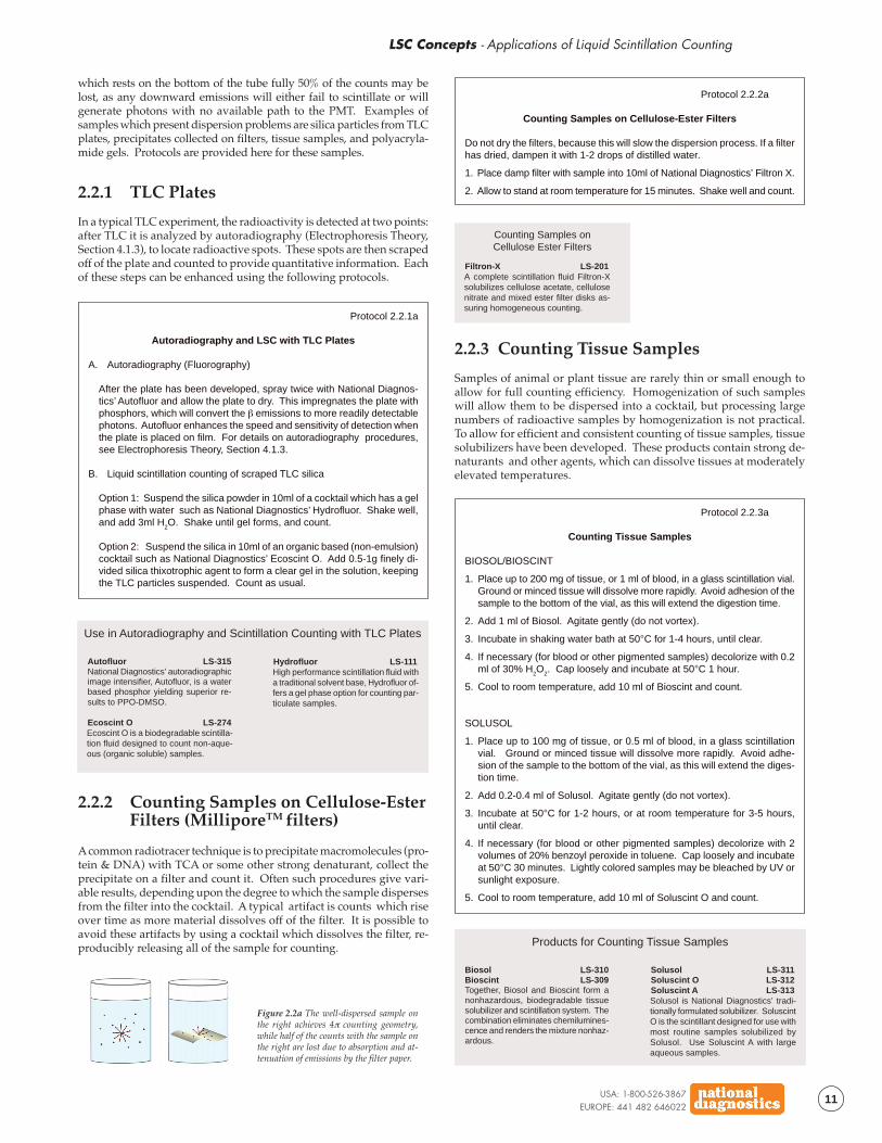
Prior to the introduction of LiquidScintillation counting, a primaryroute of radiotracer analysis wasto combust the organic materialand detect the 14CO2 so generatedin a gas phase proportionalcounter. Many protocols still callfor combustion and 14CO2 count-ing, and many metabolic studiesrequire quantitation of 14CO2 ex-haled by tracer-fed animals. 14CO2is assayed by trapping it in a liq-uid phase as a complex with astrong base (carbamate) and thencounting the liquid phase.
Protocol 2.2.4a
Counting 14CO2
OXOSOL C14
This is a single solution containing both carbamate and scintillators. Gascontaining 14CO2 is shaken with the cocktail or bubbled through with asparger. It is advisable to extract the gas with a second volume of solutionto ensure capture of >90% of the 14CO2 . Cap the vials and count.
CARBAMATE-1 + OXOSOL 306
In this system, the carbamate is provided as a separate solution, whichmay enhance capture efficiencies. Shake or bubble the gas with 1ml ofcarbamate. Add 10ml of Oxosol 306 and count.
Figure 2.2.4a Bubbling 14CO2through carbamate traps the gas inthe liquid phase, yielding a suitablesample for liquid scintillationcounting.
Oxosol C14 LS-211Oxosol C 14 is a complete scintillatordesigned to absorb and count 14CO
2 pro-
duced by sample combustion.
Oxosol 306 LS-231Complete scintillation counting solutionspecifically formulated to count 14CO
2
samples trapped in Carbamate.
Products for Counting 14CO2
Carbamate-1 LS-241Carbamate-1 is a high-capacity CO
2
absorber intended to be used in con-junction with Oxosol 306. One (1) mlabsorbs 5.8mM CO
2 at saturation.
2.2.5 Samples in Polyacrylamide Gels
Complex radioactive samples are often fractionated on polyacrylamidegels. Analysis of radiolabeled samples in electrophoretic gels followthe same pattern as that on TLC plates. The gel is analyzed as a wholefor radioactive bands, which are then excised and counted to obtainquantitative results. Autofluor, described in Section 2.2.1 for TLCplates, is also excellent for enhancing autoradiography of PAGE Gels(Electrophoresis Theory, Section 4.1.3). Once bands are located andexcised, they can be dissolved using hydrogen peroxide and thencounted efficiently.
Protocol 2.2.5a
Counting Samples in Polyacrylamide Gels
AUTOFLUOR FLUOROGRAPHY OF ELECTROPHORESIS GELS
1. Stain and fix gel as usual.
2. Rinse gel for 15 minutes in deionized water to remove fixative.
3. Immerse the gel in Autofluor. Agitate gently for 30 minutes per mm of gelthickness. Pour off the Autofluor and retain for future use. LABEL ASRADIOACTIVE MATERIAL!
○ ○ ○ ○ ○ ○ ○ ○ ○ ○ ○ ○ ○ ○ ○ ○ ○ ○ ○ ○ ○ ○c o n t i n u e d
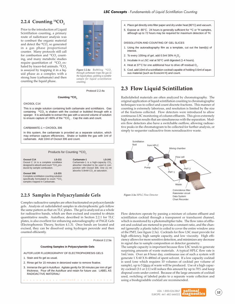
Scintillationfluid from HPLC
Pump
Mixing chamber
Flow cell
Waste
PMT 1
PMT 2
Coincidence filterRatemeter circuitData SystemChart Recorder
Figure 2.3a HPLC Flow Detector
Flow detectors operate by passing a mixture of column effluent andscintillation cocktail through a transparent or translucent channel,which is monitored by a photomultiplier tube. The flow rates of efflu-ent and cocktail are metered to provide a constant ratio, and the chan-nel (generally a plastic tube) is coiled to cover the entire window areaof the PMT, (see figure 2.3a). Cocktails for flow LSC must provide forhigh efficiency, high sample capacity, and low viscosity. High effi-ciency allows for more sensitive detection, and minimizes any decreasein signal due to sample composition or detector geometry.The sample capacity is important because flow LSC tends to generatesurprising amounts of waste materials. A typical HPLC flow rate is1ml/min. Over an 8 hour day, continuous use of such a system willgenerate 1 X 60 X 8=480ml of spent solvent. If a low capacity cocktailis used (one which requires 10 volumes of cocktail per volume ofsample), up to 5 liters of waste will be produced. Use of a high capac-ity cocktail (3:1 or 2:1) will reduce this amount by up to 70% and keepdisposal costs under control. Because of the large amounts of cocktailused, switching of labeled peaks to a separate waste collection andusing a biodegradable cocktail are recommended.

LSC Concepts - Applications of Liquid Scintillation Counting
USA: 1-800-526-3867EUROPE: 441 482 646022
13
2.4 Liquid Scintillation and RadiationSafety
Working with radioactive isotopes requires diligent attention to safetymeasures, in order to avoid hazardous exposure(s). Because radioac-tivity cannot be detected without instrumentation, spills can easily bespread through and even out of the lab before they are noticed. Safetyin radioisotope work requires sufficient attention to both containmentand surveillance. Containment measures are designed to prevent therelease of isotopes in unprotected areas. Surveillance aims to detectsuch accidental releases as rapidly as possible to prevent the spread ofcontamination.
Containment and MonitoringContainment measures are taught in radiation safety courses. A briefsummary is presented here, which is not intended as a substitute forsuch a course. The primary safeguard against radioactive spills is com-mon sense. Radioactivity should be handled only in designated ar-eas, which should be covered with disposable absorbent pads. Drop-lets of radioactive solutions will be absorbed and trapped by the pads,which are then disposed of as solid radioactive waste. Users of radio-activity must wear lab coats, gloves and eye protection. Gloves shouldbe monitored with a Geiger counter if the isotope emissions are de-tectable by this means. In any case, frequent changing of gloves ifcontamination is detected or suspected will keep exposure to a mini-mum. Shielding should be used for 125I and 32P work, or for any iso-tope whose emissions can penetrate skin, but it is important to keep inmind that the primary long term danger from radioactive componentsis through ingestion or skin absorption. Eating or drinking or evenchewing gum must be excluded from radioactive use areas.
Surveillance begins with personal dosimeters and Geiger counters.Dosimeters are most often film badges and film rings. These are wornduring radioactive experiments, and the film contained within them
Table 2.3a
Applications of National DiagnosticsFlow Scintillation Cocktails
CocktailSample Capacity
(ml /10ml cocktail) Applications
Monoflow 1Order # LS-281
Monoflow 2Order # LS-282
Monoflow 3Order # LS-283
Monoflow 4Order # LS-284
Biode-gradable
Monoflow 5Order # LS-285
Uniscint BDOrder # LS-276
N/A
3
5
3
3
3
Organic effluents. Lipid and
steroid separations.
Routine low salt aqueous
effluents (<200mM salt)
Routine low salt aqueous
effluents. Higher sample holding
capacity than Monoflow 2
High salt aqueous samples.
Can accommodate 2M salt
gradients.
Biodegradable cocktail for
routine low salt aqueous
samples (<200mM salt)
Biodegradable cocktail for high
salt aqueous samples. Can
accommodate up to 2M salt
gradients.
Ecoscint FlowOrder # LS-288
10 All purpose scintillation fluid for a
wide range of sample types.
Ultra-high sample hold.
is exposed by the emissions which affect the worker. A correlationbetween film exposure and worker exposure allows the detection ofdangerous levels of radiation in the lab. Radiation safety departmentsalso use film badges to ensure that no user exceeds their long termexposure limits in a given year. Short term monitoring of exposure tohigh-energy emissions can be done with a Geiger counter, which de-tects the ionization of a gas in a sealed tube. Only those emissionswhich are energetic enough to penetrate the tube can be detected: 32Pand the highest energy emissions from 35S. Geiger counters can beinvaluable for checking gloves for contamination during the course ofan experiment.
Wipe TestingOnce an experiment is finished, a comprehensive and sensitive checkof all work areas is required. This is accomplished by use of “wipetests”. A 4 cm2 piece of paper or other absorbent material is rubbedvigorously over the work area, placed in scintillation cocktail andcounted. If counts above background are detected, the contaminatedarea is subdivided and the divisions wipe tested. Contaminated areasare cleaned and retested until no contamination can be detected.
The type of filter used in wipe testing has a marked effect on the reli-ability of the results obtained. Often standard filter paper discs areused. Such discs generally adhere to the side or the bottom of thescintillation vial. If the vial is placed in the counter such that the filteris on the side facing the photomultiplier tube, much of the light emit-ted by the cocktail will be absorbed by the filter. This will give artifi-cially low numbers of counts, measuring contaminated areas as clean.This hazard is avoided by the use of a wipe which dissolves in thescintillation cocktail such as National Diagnostics’ Nuc-Wipes.
Efficient and effective cleaning of spills requires some knowledge ofthe chemical nature of the labeled compound. Water soluble materi-als will come off of nonabsorbent surfaces with detergent solutions.Hydrophobic compounds require the use of higher detergent concen-trations. Extremely hydrophobic compounds or absorbent surfacesmay require the use of organic solvents. If an unknown sample isspilled (spent culture medium, cellular extracts, etc.), a general pur-pose radioactive decontamination agent should be tried, such as Na-tional Diagnostics’ Nuclean, followed by solvents if necessary.
Figure 2.4b Nuc-Wipes eliminate thedependence of results on the direction ofthe filter paper and time. Because Nuc-Wipes dissolve in scintillation fluid, thereis no intact filter to absorb or attenuate betaemissions. 4π counting efficiency isachieved, giving reproducible results.
Figure 2.4a Using intact filters forenvironmental wipe tests can giveinaccurate, erratic results. β particlesoriginating from particles on intact filtersare attenuated and absorbed by the filter.Furthermore, depending on the relativeaffinity of the material for the solution, asmaterial leaves the filter for the solution,counts change over time.
Nuc-Wipes NW-300Nuc-Wipes are dissolvable wipe testpads, soluble in any scintillation solu-tion. Because Nuc-Wipes dissolve com-pletely, full 4π counting occurs, elimi-nating the lost counts due to absorp-tion by the filter, enhancing countingefficiency and reproducibility.
Products for Radiation Safety
Nuclean NC-200Nuclean is a concentrated, economicaland highly efficient solution for safe andfast removal of radioactivity from labo-ratory glassware, equipment and labo-ratory surfaces. It is also a superiorgeneral laboratory cleaner anddegreaser.
USA: 1-800-526-3867EUROPE: 441 482 646022
14
LSC Concepts - Fundamentals of Liquid Scintillation Counting
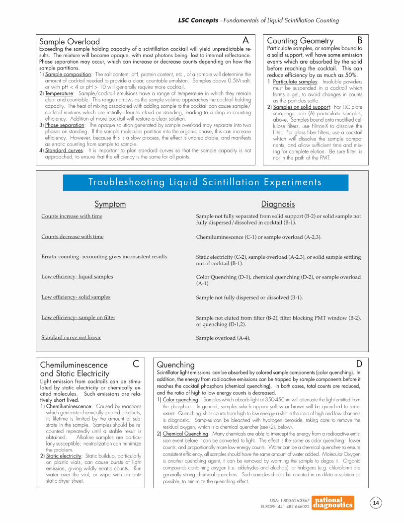
Sample OverloadExceeding the sample holding capacity of a scintillation cocktail will yield unpredictable re-sults. The mixture will become opaque, with most photons being lost to internal reflectance.Phase separation may occur, which can increase or decrease counts depending on how thesample partitions.1) Sample composition: The salt content, pH, protein content, etc., of a sample will determine the
amount of cocktail needed to provide a clear, countable emulsion. Samples above 0.5M salt,or with pH < 4 or pH > 10 will generally require more cocktail.
2) Temperature: Sample/cocktail emulsions have a range of temperature in which they remainclear and countable. This range narrows as the sample volume approaches the cocktail holdingcapacity. The heat of mixing associated with adding sample to the cocktail can cause sample/cocktail mixtures which are initially clear to cloud on standing, leading to a drop in countingefficiency. Addition of more cocktail will restore a clear solution.
3) Phase separation: The opaque solution generated by sample overload may separate into twophases on standing. If the sample molecules partition into the organic phase, this can increaseefficiency. However, because this is a slow process, the effect is unpredictable, and manifestsas erratic counting from sample to sample.
4) Standard curves: It is important to plan standard curves so that the sample capacity is notapproached, to ensure that the efficiency is the same for all points.
QuenchingScintillator light emissions can be absorbed by colored sample components (color quenching). Inaddition, the energy from radioactive emissions can be trapped by sample components before itreaches the cocktail phosphors (chemical quenching). In both cases, total counts are reduced,and the ratio of high to low energy counts is decreased.1) Color quenching: Samples which absorb light at 350-450nm will attenuate the light emitted from
the phosphors. In general, samples which appear yellow or brown will be quenched to someextent. Quenching shifts counts from high to low energy- a shift in the ratio of high and low channelsis diagnostic. Samples can be bleached with hydrogen peroxide, taking care to remove theresidual oxygen, which is a chemical quencher (see (2), below).
2) Chemical Quenching: Many chemicals are able to intercept the energy from a radioactive emis-sion event before it can be converted to light. The effect is the same as color quenching: lowercounts, and proportionally more low energy counts. Water can be a chemical quencher- to ensureconsistent efficiency, all samples should have the same amount of water added. Molecular Oxygenis another quenching agent, it can be removed by warming the sample to degas it. Organiccompounds containing oxygen (i.e. aldehydes and alcohols), or halogens (e.g. chloroform) aregenerally strong chemical quenchers. Such samples should be counted in as dilute a solution aspossible, to minimize the quenching effect.
Counting GeometryParticulate samples, or samples bound toa solid support, will have some emissionevents which are absorbed by the solidbefore reaching the cocktail. This canreduce efficiency by as much as 50%.1 Particulate samples: Insoluble powders
must be suspended in a cocktail whichforms a gel, to avoid changes in countsas the particles settle.
2) Samples on solid support: For TLC platescrapings, see (A) particulate samples,above. Samples bound onto modified cel-lulose filters, use Filtron-X to dissolve thefilter. For glass fiber filters, use a cocktailwhich will dissolve the sample compo-nents, and allow sufficient time and mix-ing for complete elution. Be sure filter isnot in the path of the PMT.
Symptom Diagnosis
Chemiluminescenceand Static ElectricityLight emission from cocktails can be stimu-lated by static electricity or chemically ex-cited molecules. Such emissions are rela-tively short lived.1) Chemiluminescence: Caused by reactions
which generate chemically excited products,its lifetime is limited by the amount of sub-strate in the sample. Samples should be re-counted repeatedly until a stable result isobtained. Alkaline samples are particu-larly susceptible; neutralization can minimizethe problem.
2) Static electricity: Static buildup, particularlyon plastic vials, can cause bursts of lightemission, giving wildly erratic counts. Runwater over the vial, or wipe with an anti-static dryer sheet.
A B
C D
Counts increase with time
Counts decrease with time
Erratic counting- recounting gives inconsistent results
Low efficiency- solid samples
Standard curve not linear
Low efficiency- liquid samples
Low efficiency- sample on filter
Troubleshoot ing L iquid Scint i l la t ion Experiments
Sample not fully separated from solid support (B-2) or solid sample notfully dispersed/dissolved in cocktail (B-1).
Static electricity (C-2), sample overload (A-2,3), or solid sample settlingout of cocktail (B-1).
Color Quenching (D-1), chemical quenching (D-2), or sample overload(A-1).
Sample not eluted from filter (B-2), filter blocking PMT window (B-2),or quenching (D-1,2).
Chemiluminescence (C-1) or sample overload (A-2,3).
Sample not fully dispersed or dissolved (B-1).
Sample overload (A-4).
LSC Concepts - Troubleshooting
USA: 1-800-526-3867EUROPE: 441 482 646022
15
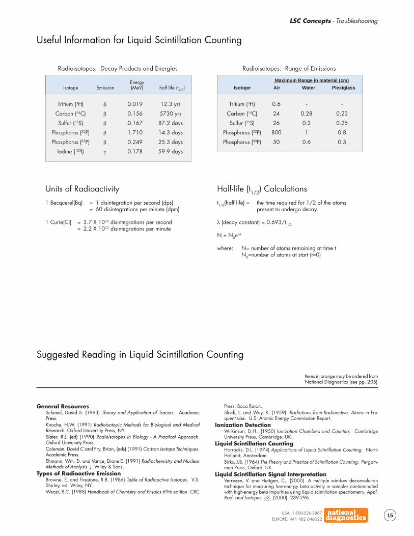
Useful Information for Liquid Scintillation Counting
Radioisotopes: Decay Products and Energies
Isotope EmissionEnergy(MeV)
Tritium (3H)
Carbon (14C)
Sulfur (35S)
Phosphorus (32P)
Phosphorus (33P)
Iodine (125I)
β
β
β
β
β
γ
half life (t1/2)
0.019
0.156
0.167
1.710
0.249
0.178
12.3 yrs
5730 yrs
87.2 days
14.3 days
25.3 days
59.9 days
Radioisotopes: Range of Emissions
Isotope Air Water
Tritium (3H)
Carbon (14C)
Sulfur (35S)
Phosphorus (32P)
Phosphorus (33P)
0.6
24
26
800
50
Plexiglass
-
0.28
0.3
1
0.6
-
0.23
0.25
0.8
0.5
Maximum Range in material (cm)
Units of Radioactivity1 Becquerel(Bq) = 1 disintegration per second (dps)
= 60 disintegrations per minute (dpm)
1 Curie(Ci) = 3.7 X 10¹⁰ disintegrations per second= 2.2 X 10¹² disintegrations per minute
Half-life (t1/2) Calculationst1/2(half life) = the time required for 1/2 of the atoms
present to undergo decay.
λ (decay constant) = 0.693/t1/2
N = N0e-λt
where: N= number of atoms remaining at time tN0=number of atoms at start (t=0)
Suggested Reading in Liquid Scintillation Counting
General ResourcesSchimel, David S. (1993) Theory and Application of Tracers. AcademicPress.Knoche, H.W. (1991) Radioisotopic Methods for Biological and MedicalResearch Oxford University Press, NY.Slater, R.J. (ed) (1990) Radioisotopes in Biology - A Practical Approach.Oxford University Press.Coleman, David C and Fry, Brian, (eds) (1991) Carbon Isotope Techniques.Academic Press.Ehmann, Wm. D. and Vance, Diane E. (1991) Radiochemistry and NuclearMethods of Analysis. J. Wiley & Sons.
Types of Radioactive EmissionBrowne, E. and Firestone, R.B. (1986) Table of Radioactive Isotopes. V.S.Shirley, ed. Wiley, NY.Weast, R.C. (1988) Handbook of Chemistry and Physics 69th edition. CRC
Items in orange may be ordered fromNational Diagnostics (see pp. 205)
Press, Boca Raton.Slack, L. and Way, K. (1959) Radiations from Radioactive Atoms in Fre-quent Use. U.S. Atomic Energy Commission Report.
Ionization DetectionWilkinson, D.H., (1950) Ionization Chambers and Counters. CambridgeUniversity Press, Cambridge, UK.
Liquid Scintillation CountingHorrocks, D.L. (1974) Applications of Liquid Scintillation Counting. NorthHolland, AmsterdamBirks, J.B. (1964) The Theory and Practice of Scintillation Counting. Pergam-mon Press, Oxford, UK.
Liquid Scintillation Signal InterpretationVerrezen, V. and Hurtgen, C., (2000) A multiple window deconvolutiontechnique for measuring low-energy beta activity in samples contaminatedwith high-energy beta impurities using liquid scintillation spectrometry. Appl.Rad. and Isotopes 53 (2000) 289-296.