PRIME HT - Thermoland, Συστήματα Ενέργειας HT 0085 GB 2 INSTRUCTIONS FOR THE USER...
40
Wall-mounted condensing boilers Installerʼs and Userʼs Instructions BAXI S.p.A. is a leading European manufacturer of central heating and domestic hot water appliances (wall mounted gas boilers, floor standing boilers, electric water heaters) and has been certified by CSQ as conforming to UNI EN ISO 9001. This certification confirms that the Quality System of BAXI S.p.A. in Bassano del Grappa, where this boiler was manufactured, satisfies the strict UNI EN ISO 9001 standard covering all aspects of company organisation, manufacturing and distribution. UNI EN ISO 9001 CERTIFICAZIONE DEI SISTEMI QUALITA' DELLE AZIENDE PRIME HT 0085 GB
Transcript of PRIME HT - Thermoland, Συστήματα Ενέργειας HT 0085 GB 2 INSTRUCTIONS FOR THE USER...

Wall-mounted condensing boilers
Installerʼs and Userʼs Instructions
BAXI S.p.A. is a leading European manufacturer of central heating and domestic hot water appliances (wall mounted gas boilers, floor standing boilers, electric water heaters) and has been certified by CSQ as conforming to UNI EN ISO 9001.This certification confirms that the Quality System of BAXI S.p.A. in Bassano del Grappa, where this boiler was manufactured, satisfies the strict UNI EN ISO 9001 standard covering all aspects of company organisation, manufacturing and distribution.
UNI EN ISO 9001
CERTIFICAZIONE DEI SISTEMIQUALITA' DELLE AZIENDE
PRIME HT
0085
GB
2
INSTRUCTIONS FOR THE USER
Dear Customer,
We are sure your new boiler will comply with all your require-ments.
Purchasing one of the BAXI products satisfies your expecta-tions: good functioning, simplicity and ease of use.
Do not dispose of this booklet without reading it: you can find here some very useful information, which will help you to run your boiler correctly and efficiently.
Do not leave any parts of the packaging (plastic bags, polystyrene, etc.) within children’s reach as they are a potential source of danger.
BAXI boilers bear the CE mark in compliance with the basic requirements as laid down in the following Directives:- Gas Directive 90/396/CEE- Performance Directive 92/42/CEE- Electromagnetic Compatibility Directive 89/336/CEE- Low Voltage Directive 73/23/CEE
3
INSTRUCTIONS FOR THE USER
9. General information 910. Instructions prior to installation 911. Boiler installation 1012. Boiler size 1013. Fittings present in the packaging 1114. Installation of flue and air ducts 1115. Connecting the mains supply 1516. Changing gas type 2217. Displaying electronic control card parameters on the boiler display (“INFO” mode) 2518. Control and operation devices 2719. Positioning of the ignition and flame sensing electrode 2820. Check of combustion parameters 2821. Activating the flue-sweeper function 2922. Output / pump head performances 2923. How to disassemble the DHW heat exchanger 3024. Cleaning the cold water filter 3025. Annual service 3026. Using the Siemens QAA73 temperature regulator to program boiler parameters 3127. Boiler schematic 33-3428. Illustrated wiring diagram 35-3629. Technical data 40
1. Instructions prior to installation 42. Instructions prior to commissioning 53. Commissioning of the boiler 54. Filling the boiler 75. Switching the boiler off 86. Prolonged standstill of the system. Frost protection 87. Gas change 88. Servicing instructions 8
CONTENTS
INSTRUCTIONS PERTAINING TO THE USER
INSTRUCTIONS PERTAINING TO THE INSTALLER
4
INSTRUCTIONS FOR THE USER
This boiler is designed to heat water at a lower than boiling temperature at atmospheric pressure. The boiler must be connected to a central heating system and to a domestic hot water supply system in compliance with its performances and output power.Have the boiler installed by a Qualified Service Engineer and ensure the following operations are accomplished:
This boiler is designed to heat water at a lower than boiling temperature at atmospheric pressure. The boiler must be connected to a central heating system and to a domestic hot water supply system in compliance with its performances and output power.Have the boiler installed by a Qualified Service Engineer and ensure the following operations are accom-plished:
a) careful checking that the boiler is fit for operation with the type of gas available. For more details see the notice on the packaging and the label on the appliance itself.
b) careful checking that the flue terminal draft is appropriate; that the terminal is not obstructed and that no other appliance exhaust gases are expelled through the same flue duct, unless the flue is especially de-signed to collect the exhaust gas coming from more than one appliance, in conformity with the laws and regulations in force.
c) careful checking that, in case the flue has been connected to pre-existing flue ducts, thorough cleaning has been carried out in that residual combustion products may come off during operation of the boiler and obstruct the flue duct.
d) to ensure correct operation of the appliance and avoid invalidating the guarantee, observe the following precautions:
1. Hot water circuit:
1.1. If the water hardness is greater than 20 °F (1 °F = 10 mg calcium carbonate per litre of water) a polyphosphate or comparable treatment system responding to current regulations.
1.2. Domestic Hot Water circuit must be thoroughly flushed after the installation of the appliance and before its use.
2. Heating circuit
2.1. new system Before proceeding with installation of the boiler, the system must be cleaned and flushed out thoroughly
to eliminate residual thread-cutting swarf, solder and solvents if any, using suitable proprietary products.
To avoid damaging metal, plastic and rubber parts, use only neutral cleaners, i.e. non-acid and non alkaline. The recommended products for cleaning are:
SENTINEL X300 or X400 and FERNOX heating circuit restore. To use this product proceeding strictly in accordance with the maker’s directions.
2.2. existing system Before proceeding with installation of the boiler, the system must be cleaned and flushed out to remove
sludge and contaminants, using suitable proprietary products as described in section 2.1. To avoid damaging metal, plastic and rubber parts, use only neutral cleaners, i.e. non-acid and non-
alkaline such as SENTINEL X100 and FERNOX heating circuit protective. To use this product proceeding strictly in accordance with the maker’s directions.
Remember that the presence of foreign matter in the heating system can adversely affect the operation of the boiler (e.g. overheating and noisy operation of the heat exchanger).
Failure to observe the above will render the guarantee null and void.
1. INSTRUCTIONS PRIOR TO INSTALLATION
5
INSTRUCTIONS FOR THE USER
0402_2501
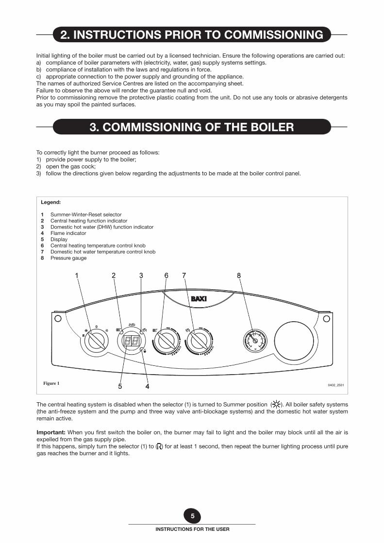
The central heating system is disabled when the selector (1) is turned to Summer position ( ). All boiler safety systems (the anti-freeze system and the pump and three way valve anti-blockage systems) and the domestic hot water system remain active.
Important: When you first switch the boiler on, the burner may fail to light and the boiler may block until all the air is expelled from the gas supply pipe.If this happens, simply turn the selector (1) to ( ) for at least 1 second, then repeat the burner lighting process until pure gas reaches the burner and it lights.
Legend:
1 Summer-Winter-Reset selector2 Central heating function indicator3 Domestic hot water (DHW) function indicator4 Flame indicator5 Display6 Central heating temperature control knob7 Domestic hot water temperature control knob 8 Pressure gauge
Figure 1
To correctly light the burner proceed as follows:1) provide power supply to the boiler;2) open the gas cock;3) follow the directions given below regarding the adjustments to be made at the boiler control panel.
Initial lighting of the boiler must be carried out by a licensed technician. Ensure the following operations are carried out:a) compliance of boiler parameters with (electricity, water, gas) supply systems settings.b) compliance of installation with the laws and regulations in force.c) appropriate connection to the power supply and grounding of the appliance.The names of authorized Service Centres are listed on the accompanying sheet. Failure to observe the above will render the guarantee null and void.Prior to commissioning remove the protective plastic coating from the unit. Do not use any tools or abrasive detergents as you may spoil the painted surfaces.
2. INSTRUCTIONS PRIOR TO COMMISSIONING
3. COMMISSIONING OF THE BOILER
6
INSTRUCTIONS FOR THE USER
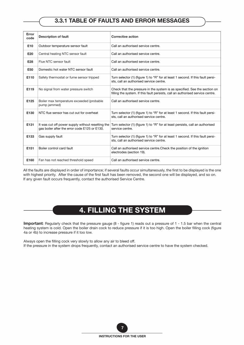
If a fault occurs, the display reads out an error message identifying it.
Note: If the error message contains more than 2 digits (e.g. E133), the display reads out the first two digits “E1” followed, by the last two digits “33”, as shown in figure 3.
Figure 3 0402_2504
3.3 ERROR MESSAGES AND RESETTING THE BOILER
Figure 2
0403
_250
1
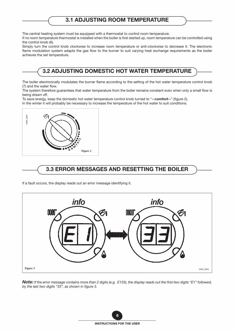
The boiler electronically modulates the burner flame according to the setting of the hot water temperature control knob (7) and the water flow.The system therefore guarantees that water temperature from the boiler remains constant even when only a small flow is being drawn off.To save energy, keep the domestic hot water temperature control knob turned to “--comfort--” (figure 2).In the winter it will probably be necessary to increase the temperature of the hot water to suit conditions.
3.2 ADJUSTING DOMESTIC HOT WATER TEMPERATURE
The central heating system must be equipped with a thermostat to control room temperature.If no room temperature thermostat is installed when the boiler is first started up, room temperature can be controlled using the control knob (6).Simply turn the control knob clockwise to increase room temperature or anti-clockwise to decrease it. The electronic flame modulation system adapts the gas flow to the burner to suit varying heat exchange requirements as the boiler achieves the set temperature.
3.1 ADJUSTING ROOM TEMPERATURE
7
INSTRUCTIONS FOR THE USER
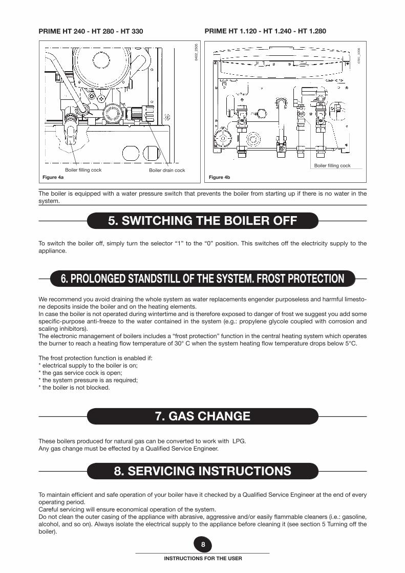
Important: Regularly check that the pressure gauge (8 - figure 1) reads out a pressure of 1 - 1.5 bar when the central heating system is cold. Open the boiler drain cock to reduce pressure if it is too high. Open the boiler filling cock (figure 4a or 4b) to increase pressure if it too low.
Always open the filling cock very slowly to allow any air to bleed off.If the pressure in the system drops frequently, contact an authorised service centre to have the system checked.
4. FILLING THE SYSTEM
Corrective action
Call an authorised service centre.
Call an authorised service centre.
Call an authorised service centre.
Call an authorised service centre.
Turn selector (1) (figure 1) to “R” for at least 1 second. If this fault persi-sts, call an authorised service centre.
Check that the pressure in the system is as specified. See the section on filling the system. If this fault persists, call an authorised service centre.
Call an authorised service centre.
Turn selector (1) (figure 1) to “R” for at least 1 second. If this fault persi-sts, call an authorised service centre.
Turn selector (1) (figure 1) to “R” for at least persists, call an authorised service centre.
Turn selector (1) (figure 1) to “R” for at least 1 second. If this fault persi-sts, call an authorised service centre.
Call an authorised service centre.Check the position of the ignition electrodes (section 19).
Call an authorised service centre.
Description of fault
Outdoor temperature sensor fault Central heating NTC sensor fault
Flue NTC sensor fault
Domestic hot water NTC sensor fault
Safety thermostat or fume sensor tripped
No signal from water pressure switch
Boiler max temperature exceeded (probable pump jammed)
NTC flue sensor has cut out for overheat
It was cut off power supply without resetting the gas boiler after the error code E125 or E130.
Gas supply fault
Boiler control card fault
Fan has not reached threshold speed
Errorcode
E10
E20
E28
E50
E110
E119
E125
E130
E131
E133
E151
E160
All the faults are displayed in order of importance; if several faults occur simultaneously, the first to be displayed is the one with highest priority. After the cause of the first fault has been removed, the second one will be displayed, and so on.If any given fault occurs frequently, contact the authorised Service Centre.
3.3.1 TABLE OF FAULTS AND ERROR MESSAGES
8
INSTRUCTIONS FOR THE USER
We recommend you avoid draining the whole system as water replacements engender purposeless and harmful limesto-ne deposits inside the boiler and on the heating elements.In case the boiler is not operated during wintertime and is therefore exposed to danger of frost we suggest you add some specific-purpose anti-freeze to the water contained in the system (e.g.: propylene glycole coupled with corrosion and scaling inhibitors).The electronic management of boilers includes a “frost protection” function in the central heating system which operates the burner to reach a heating flow temperature of 30° C when the system heating flow temperature drops below 5°C.
The frost protection function is enabled if:* electrical supply to the boiler is on;* the gas service cock is open;* the system pressure is as required;* the boiler is not blocked.
These boilers produced for natural gas can be converted to work with LPG. Any gas change must be effected by a Qualified Service Engineer.
To maintain efficient and safe operation of your boiler have it checked by a Qualified Service Engineer at the end of every operating period.Careful servicing will ensure economical operation of the system.Do not clean the outer casing of the appliance with abrasive, aggressive and/or easily flammable cleaners (i.e.: gasoline, alcohol, and so on). Always isolate the electrical supply to the appliance before cleaning it (see section 5 Turning off the boiler).
6. PROLONGED STANDSTILL OF THE SYSTEM. FROST PROTECTION
7. GAS CHANGE
8. SERVICING INSTRUCTIONS
To switch the boiler off, simply turn the selector “1” to the “0” position. This switches off the electricity supply to the appliance.
The boiler is equipped with a water pressure switch that prevents the boiler from starting up if there is no water in the system.
5. SWITCHING THE BOILER OFF
Boiler filling cock Boiler drain cock
Figure 4a
PRIME HT 240 - HT 280 - HT 330 PRIME HT 1.120 - HT 1.240 - HT 1.280
0301
_100
8
Boiler filling cock
Figure 4b
0402
_250
5
9
INSTRUCTIONS FOR THE INSTALLER
This boiler is designed to heat water at a lower than boiling temperature at atmospheric pressure. The boiler must be connected to a central heating system and to a domestic hot water supply system in compliance with its performances and output power.Have the boiler installed by a Qualified Service Engineer and ensure the following operations are accomplished:
a) careful checking that the boiler is fit for operation with the type of gas available. For more details see the notice on the packaging and the label on the appliance itself.
b) careful checking that the flue terminal draft is appropriate; that the terminal is not obstructed and that no other appliance exhaust gases are expelled through the same flue duct, unless the flue is especially designed to collect the exhaust gas coming from more than one appliance, in conformity with the laws and regulations in force.
c) careful checking that, in case the flue has been connected to pre-existing flue ducts, thorough cleaning has been carried out in that residual combustion products may come off during operation of the boiler and obstruct the flue duct.
To ensure correct operation of the appliance and avoid invalidating the guarantee, observe the following precautions:
1. Hot water circuit:
1.1. If the water hardness is greater than 20 °F (1 °F = 10 mg calcium carbonate per litre of water) a polyphosphate or comparable treatment system responding to current regulations.
1.2. Domestic Hot Water circuit must be thoroughly flushed after the installation of the appliance and before its use.
2. Heating circuit
2.1. new system Before proceeding with installation of the boiler, the system must be cleaned and flushed out thoroughly to eliminate
residual thread-cutting swarf, solder and solvents if any, using suitable proprietary products. To avoid damaging metal, plastic and rubber parts, use only neutral cleaners, i.e. non-acid and non alkaline. The
recommended products for cleaning are: SENTINEL X300 or X400 and FERNOX heating circuit restore. To use this product proceeding strictly in accordance
with the maker’s directions.
2.2. existing system Before proceeding with installation of the boiler, the system must be cleaned and flushed out to remove sludge and
contaminants, using suitable proprietary products as described in section 2.1. To avoid damaging metal, plastic and rubber parts, use only neutral cleaners, i.e. non-acid and non-
alkaline such as SENTINEL X100 and FERNOX heating circuit protective. To use this product proceeding strictly in accordance with the maker’s directions.
Remember that the presence of foreign matter in the heating system can adversely affect the operation of the boiler (e.g. overheating and noisy operation of the heat exchanger).
Failure to observe the above will render the guarantee null and void.
The following remarks and instructions are addressed to Service Engineers to help them carry out a faultless installation. Instructions regarding lighting and operation of the boiler are contained in the ‘Instructions pertaining to the user’ section.Note that installation, maintenance and operation of the domestic gas appliances must be performed exclusively by qua-lified personnel in compliance with current standards.Please note the following:* This boiler can be connected to any type of double- or single feeding pipe convector plates, radiators, thermocon-
vectors. Design the system sections as usual though taking into account the available output / pump head performan-ces, as shown in chapter 22.
* Do not leave any packaging components (plastic bags, polystyrene, etc.) within children’s reach as they are a potential source of danger.
* Initial lighting of the boiler must be effected by a Qualified Service Engineer.
Note: Failure to observe the above will render the guarantee null and void.
9. GENERAL INFORMATION
10. INSTRUCTIONS PRIOR TO INSTALLATION
10
INSTRUCTIONS FOR THE INSTALLER
Figure 6
0402
_250
6
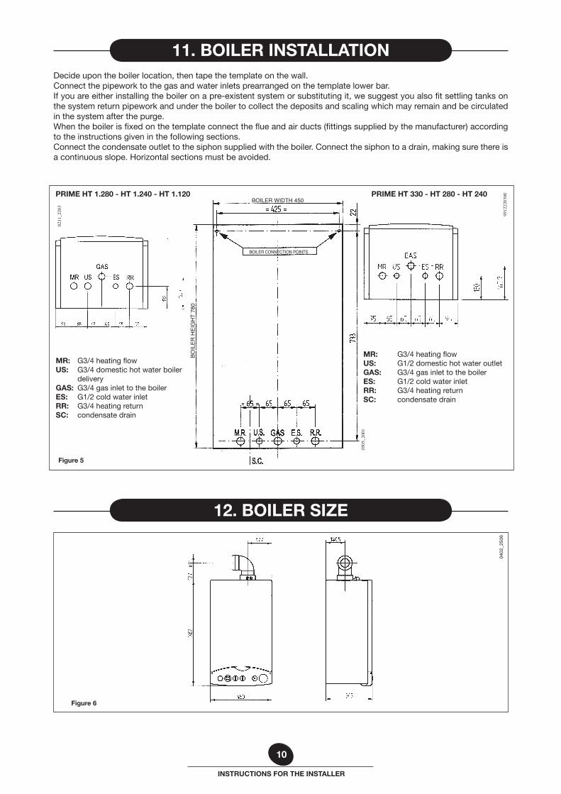
Decide upon the boiler location, then tape the template on the wall.Connect the pipework to the gas and water inlets prearranged on the template lower bar.If you are either installing the boiler on a pre-existent system or substituting it, we suggest you also fit settling tanks on the system return pipework and under the boiler to collect the deposits and scaling which may remain and be circulated in the system after the purge.When the boiler is fixed on the template connect the flue and air ducts (fittings supplied by the manufacturer) according to the instructions given in the following sections.Connect the condensate outlet to the siphon supplied with the boiler. Connect the siphon to a drain, making sure there is a continuous slope. Horizontal sections must be avoided.
11. BOILER INSTALLATION
12. BOILER SIZE
0505
_200
1
Figure 5
9912
2203
00
BOILER WIDTH 450
BOILER CONNECTION POINTS
BOIL
ER H
EIG
HT
780
0211
_220
3
PRIME HT 1.280 - HT 1.240 - HT 1.120 PRIME HT 330 - HT 280 - HT 240
MR: G3/4 heating flowUS: G1/2 domestic hot water outletGAS: G3/4 gas inlet to the boilerES: G1/2 cold water inletRR: G3/4 heating returnSC: condensate drain
MR: G3/4 heating flowUS: G3/4 domestic hot water boiler
deliveryGAS: G3/4 gas inlet to the boilerES: G1/2 cold water inletRR: G3/4 heating returnSC: condensate drain

11
INSTRUCTIONS FOR THE INSTALLER
0108
28_0
200
C33 C33
C13 C13
C43 C53 C83
Figure 8
Figure 7a
0301
_100
7
181716
19
PRIME HT 240 - HT 280 - HT 330
Figure 7b
0301
_100
8
18171619
PRIME HT 1.120 - HT 1.240 - HT 1.280
• template• gas cock (16)• inlet water tap with filter (17)• heating system delivery cock (19)• heating system return cock (18)• seals• telescopic joints• 8 mm wall plugs and hooks
We guarantee ease and flexibility of installation for a gas-fired forced draft boiler thanks to the fittings and fixtures sup-plied (described below).The boiler is especially designed for connection to an exhaust flue / air ducting, with either coaxial, vertical or horizontal terminal. By means of a splitting kit a two-pipe system may also be installed.In case exhaust and intake flues not supplied by BAXI S.p.A. have been installed, these must be certified for the type of use and must have a maximum pressure drop of 100 Pa.
Warnings for the following types of installation:
C13, C33 The terminals for the split flue must be provided for within a square with 50 cm sides. Detailed instructions are given together with each accessory.
C53 The terminals for combustion air intake and for the expulsion of combu-stion products must not be provided for on opposite walls of the building.
C63 The maximum pressure drop of the ducts must not exceed 100 Pa. The ducts must be certified for the specific use and for a temperature of over 100°C. The chimney flue must be certified in accordance with the prEN 1856-1 Regulation.
C43, C83 The chimney or flue used must be suitable for the use.
14. INSTALLATION OF FLUE AND AIR DUCTS
13. FITTINGS PRESENT IN THE PACKAGING
12
INSTRUCTIONS FOR THE INSTALLER
L max = 10 m
9912
2209
00
L max = 10 m L max = 10 m
L max = 9 m
L max = 9 m
0002
2304
00
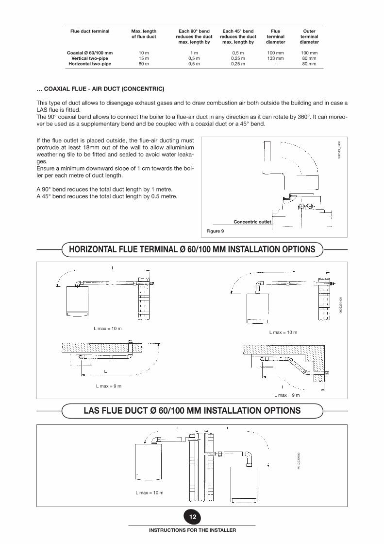
Flueterminal diameter
100 mm133 mm
-
Each 45° bendreduces the ductmax. length by
0,5 m0,25 m0,25 m
Each 90° bendreduces the ductmax. length by
1 m0,5 m0,5 m
Max. length of flue duct
10 m15 m80 m
Flue duct terminal
Coaxial Ø 60/100 mmVertical two-pipe
Horizontal two-pipe
Outerterminal diameter
100 mm80 mm80 mm
… COAXIAL FLUE - AIR DUCT (CONCENTRIC)
This type of duct allows to disengage exhaust gases and to draw combustion air both outside the building and in case a LAS flue is fitted.The 90° coaxial bend allows to connect the boiler to a flue-air duct in any direction as it can rotate by 360°. It can moreo-ver be used as a supplementary bend and be coupled with a coaxial duct or a 45° bend.
9905
19_0
400
Concentric outlet
Figure 9
LAS FLUE DUCT Ø 60/100 MM INSTALLATION OPTIONS
HORIZONTAL FLUE TERMINAL Ø 60/100 MM INSTALLATION OPTIONS
If the flue outlet is placed outside, the flue-air ducting must protrude at least 18mm out of the wall to allow alluminium weathering tile to be fitted and sealed to avoid water leaka-ges.Ensure a minimum downward slope of 1 cm towards the boi-ler per each metre of duct length.
A 90° bend reduces the total duct length by 1 metre.A 45° bend reduces the total duct length by 0.5 metre.
13
INSTRUCTIONS FOR THE INSTALLER
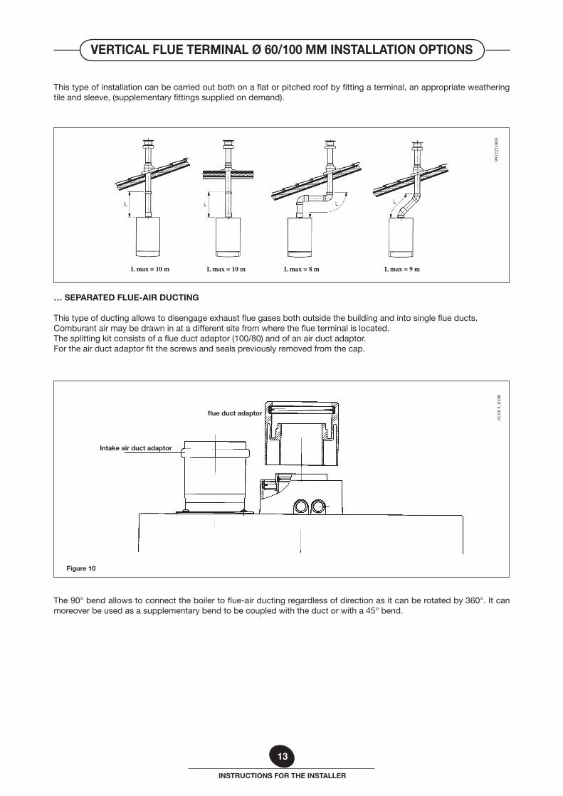
This type of installation can be carried out both on a flat or pitched roof by fitting a terminal, an appropriate weathering tile and sleeve, (supplementary fittings supplied on demand).
L max = 10 m L max = 10 m L max = 9 mL max = 8 m
9912
2210
00
… SEPARATED FLUE-AIR DUCTING
This type of ducting allows to disengage exhaust flue gases both outside the building and into single flue ducts.Comburant air may be drawn in at a different site from where the flue terminal is located.The splitting kit consists of a flue duct adaptor (100/80) and of an air duct adaptor. For the air duct adaptor fit the screws and seals previously removed from the cap.
0110
15_0
100
flue duct adaptor
Intake air duct adaptor
The 90° bend allows to connect the boiler to flue-air ducting regardless of direction as it can be rotated by 360°. It can moreover be used as a supplementary bend to be coupled with the duct or with a 45° bend.
Figure 10
VERTICAL FLUE TERMINAL Ø 60/100 MM INSTALLATION OPTIONS
14
INSTRUCTIONS FOR THE INSTALLER
0402
_250
7
Figure 11
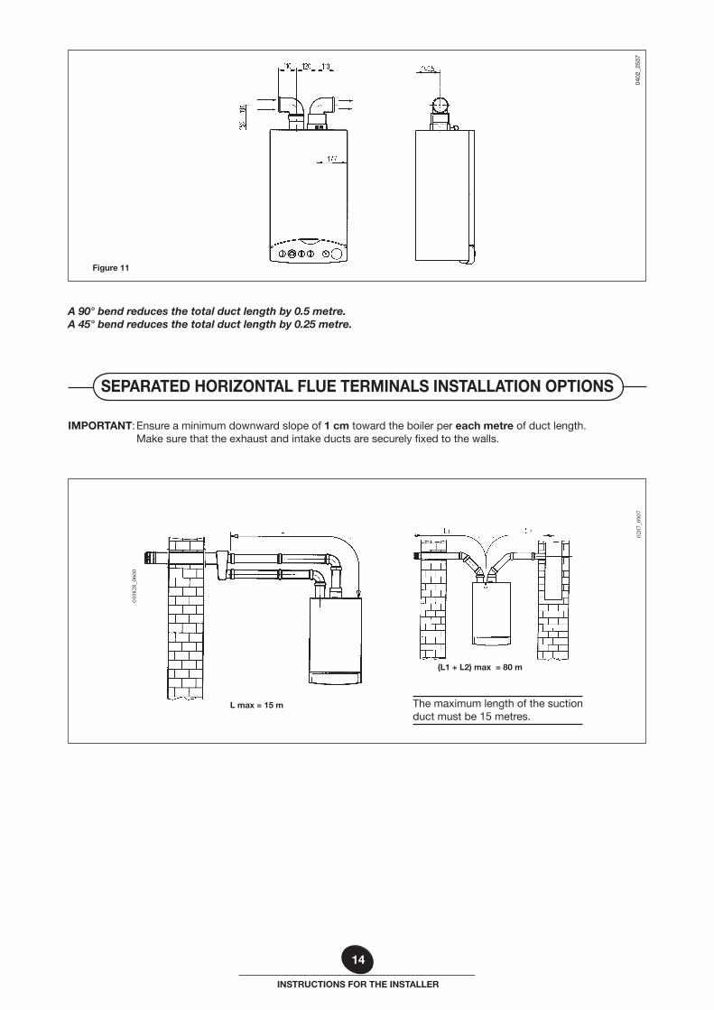
A 90° bend reduces the total duct length by 0.5 metre.A 45° bend reduces the total duct length by 0.25 metre.
IMPORTANT: Ensure a minimum downward slope of 1 cm toward the boiler per each metre of duct length. Make sure that the exhaust and intake ducts are securely fixed to the walls.
(L1 + L2) max = 80 m
L max = 15 m
0207
_090
7
0108
28_0
600
The maximum length of the suction duct must be 15 metres.
SEPARATED HORIZONTAL FLUE TERMINALS INSTALLATION OPTIONS
15
INSTRUCTIONS FOR THE INSTALLER
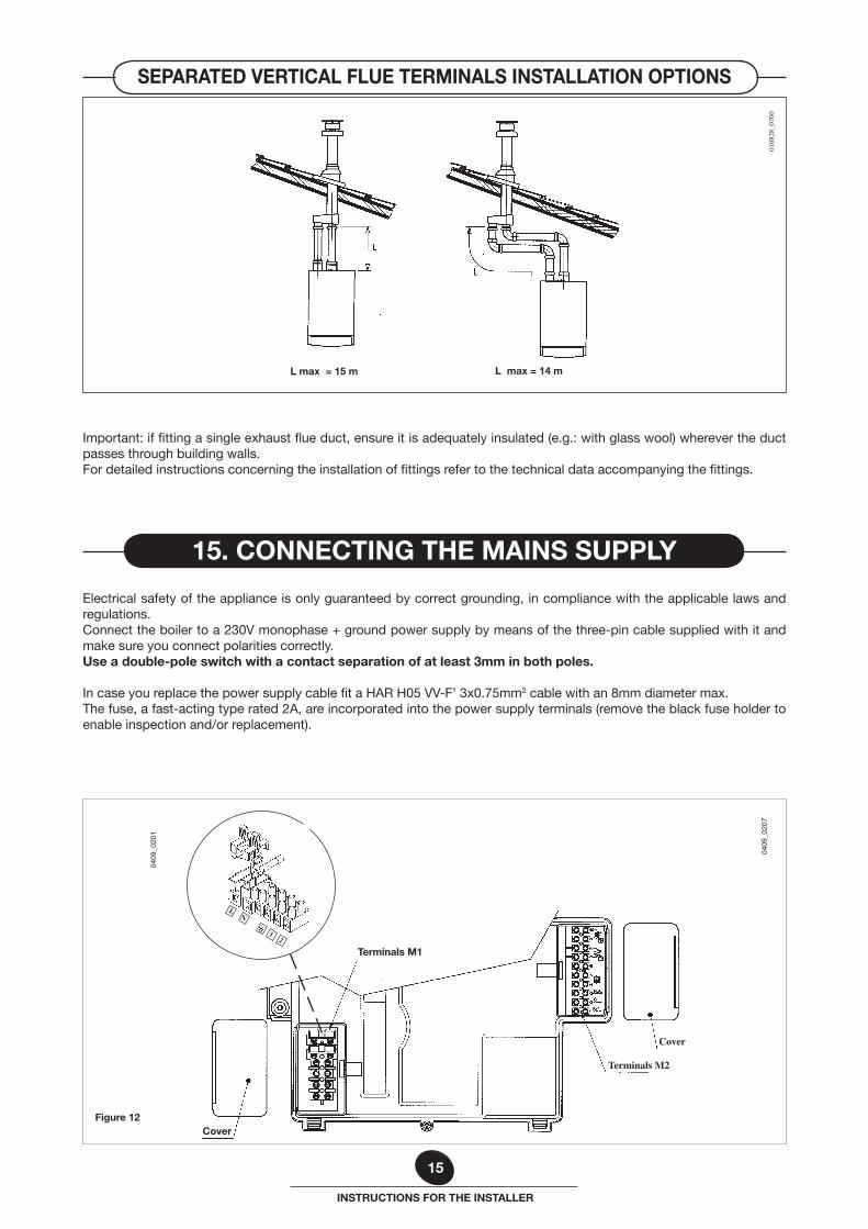
Important: if fitting a single exhaust flue duct, ensure it is adequately insulated (e.g.: with glass wool) wherever the duct passes through building walls.For detailed instructions concerning the installation of fittings refer to the technical data accompanying the fittings.
L max = 14 mL max = 15 m
0108
28_0
700
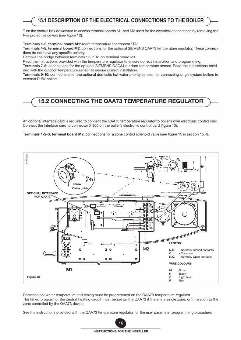
Electrical safety of the appliance is only guaranteed by correct grounding, in compliance with the applicable laws and regulations.Connect the boiler to a 230V monophase + ground power supply by means of the three-pin cable supplied with it and make sure you connect polarities correctly.Use a double-pole switch with a contact separation of at least 3mm in both poles.
In case you replace the power supply cable fit a HAR H05 VV-F’ 3x0.75mm2 cable with an 8mm diameter max.The fuse, a fast-acting type rated 2A, are incorporated into the power supply terminals (remove the black fuse holder to enable inspection and/or replacement).
Figure 12
0409
_020
7
Terminals M1
Terminals M2
Cover
Cover
0409
_020
1
21
NL
15. CONNECTING THE MAINS SUPPLY
SEPARATED VERTICAL FLUE TERMINALS INSTALLATION OPTIONS
16
INSTRUCTIONS FOR THE INSTALLER
Turn the control box downward to access terminal boards M1 and M2 used for the electrical connections by removing the two protective covers (see figure 12).
Terminals 1-2, terminal board M1: room temperature thermostat “TA”.Terminals 4-5, terminal board M2: connections for the optional SIEMENS QAA73 temperature regulator. These connec-tions do not have any specific polarity.Remove the bridge between terminals 1-2 “TA” on terminal board M1.Read the instructions provided with the temperature regulator to ensure correct installation and programming.Terminals 7-8: connections for the optional SIEMENS QAC34 outdoor temperature sensor. Read the instructions provi-ded with the outdoor temperature sensor to ensure correct installation.Terminals 9-10: connections for the optional domestic hot water priority sensor, for connecting single system boilers to external DHW boilers.
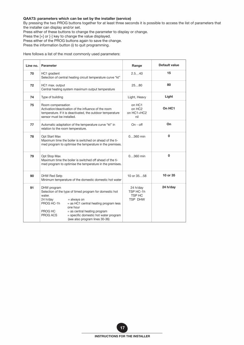
An optional interface card is required to connect the QAA73 temperature regulator to boiler’s own electronic control card.Connect the interface card to connector X 300 on the boiler’s electronic control card (figure 13).
Terminals 1-2-3, terminal board M2: connections for a zone control solenoid valve (see figure 15 in section 15.4).
Domestic hot water temperature and timing must be programmed on the QAA73 temperature regulator.The timed program of the central heating circuit must be set on the QAA73 if there is a single zone, or in relation to the zone controlled by the QAA73 device.
See the instructions provided with the QAA73 temperature regulator for the user parameter programming procedure.
15.1 DESCRIPTION OF THE ELECTRICAL CONNECTIONS TO THE BOILER
15.2 CONNECTING THE QAA73 TEMPERATURE REGULATOR
0403
_250
2
Screw
Figure 13
Cable guide
LEGEND:
N.C. - Normally Closed contactsC - CommonN.O. - Normally Open contacts
WIRE COLOURS:
M BrownN BlackC Light blueR Red
OPTIONAL INTERFACEFOR QAA73
17
INSTRUCTIONS FOR THE INSTALLER
QAA73: parameters which can be set by the installer (service)By pressing the two PROG buttons together for at least three seconds it is possible to access the list of parameters that the installer can display and/or set.Press either of these buttons to change the parameter to display or change.Press the [+] or [-] key to change the value displayed.Press either of the PROG buttons again to save the change.Press the information button (i) to quit programming.
Here follows a list of the most commonly used parameters:
Line no.
70
72
74
75
77
78
79
90
91
Default value
15
80
Light
On HC1
On
0
0
10 or 35
24 h/day
Range
2.5…40
25…80
Light, Heavy
on HC1on HC2
on HC1+HC2 nil
On - off
0…360 min
0…360 min
10 or 35…58
24 h/day TSP HC-1h
TSP HCTSP DHW
Parameter
HC1 gradient Selection of central heating circuit temperature curve “kt”
HC1 max. output Central heating system maximum output temperature
Type of building
Room compensation Activation/deactivation of the influence of the room temperature. If it is deactivated, the outdoor temperature sensor must be installed.
Automatic adaptation of the temperature curve “kt” in relation to the room temperature.
Opt Start MaxMaximum time the boiler is switched on ahead of the ti-med program to optimise the temperature in the premises.
Opt Stop Max Maximum time the boiler is switched off ahead of the ti-med program to optimise the temperature in the premises.
DHW Red SetpMinimum temperature of the domestic domestic hot water DHW programSelection of the type of timed program for domestic hot water.24 h/day = always on PROG HC-1h = as HC1 central heating program less
one hour PROG HC = as central heating programPROG ACS = specific domestic hot water program
(see also program lines 30-36)
18
INSTRUCTIONS FOR THE INSTALLER
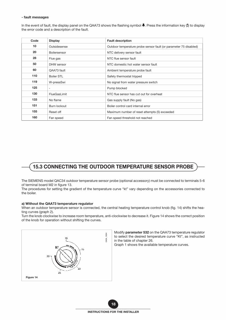
The SIEMENS model QAC34 outdoor temperature sensor probe (optional accessory) must be connected to terminals 5-6 of terminal board M2 in figure 13.The procedures for setting the gradient of the temperature curve “kt” vary depending on the accessories connected to the boiler.
0404
_160
4
Figure 14
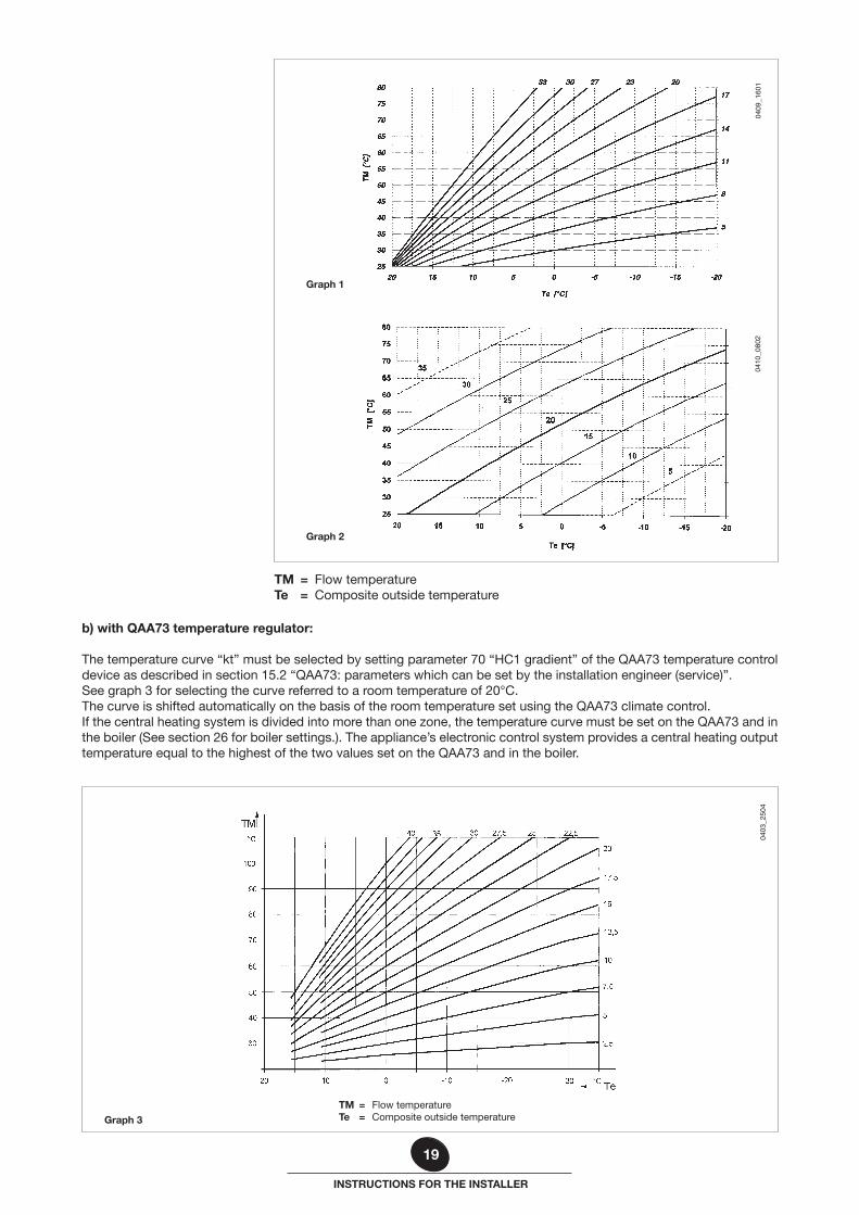
a) Without the QAA73 temperature regulatorWhen an outdoor temperature sensor is connected, the central heating temperature control knob (fig. 14) shifts the hea-ting curves (graph 2).Turn the knob clockwise to increase room temperature, anti-clockwise to decrease it. Figure 14 shows the correct position of the knob for operation without shifting the curves.
Modify parameter 532 on the QAA73 temperature regulator to select the desired temperature curve “Kt”, as instructed in the table of chapter 26.Graph 1 shows the available temperature curves.
15.3 CONNECTING THE OUTDOOR TEMPERATURE SENSOR PROBE
- fault messages
In the event of fault, the display panel on the QAA73 shows the flashing symbol . Press the information key ( ) to display the error code and a description of the fault.
Code Display Fault description
10 Outsidesense Outdoor temperature probe sensor fault (or parameter 75 disabled)
20 Boilersensor NTC delivery sensor fault
28 Flue gas NTC flue sensor fault
50 DHW sensor NTC domestic hot water sensor fault
60 QAA73 fault Ambient temperature probe fault
110 Boiler STL Safety thermostat tripped
119 W-pressSwi No signal from water pressure switch
125 - Pump blocked
130 FlueGasLimit NTC flue sensor has cut out for overheat
133 No flame Gas supply fault (No gas)
151 Burn lockout Boiler control card internal error
155 Reset off Maximum number of reset attempts (5) exceeded
160 Fan speed Fan speed threshold not reached
19
INSTRUCTIONS FOR THE INSTALLER
b) with QAA73 temperature regulator:
The temperature curve “kt” must be selected by setting parameter 70 “HC1 gradient” of the QAA73 temperature control device as described in section 15.2 “QAA73: parameters which can be set by the installation engineer (service)”.See graph 3 for selecting the curve referred to a room temperature of 20°C.The curve is shifted automatically on the basis of the room temperature set using the QAA73 climate control.If the central heating system is divided into more than one zone, the temperature curve must be set on the QAA73 and in the boiler (See section 26 for boiler settings.). The appliance’s electronic control system provides a central heating output temperature equal to the highest of the two values set on the QAA73 and in the boiler.
Graph 3
TM = Flow temperature Te = Composite outside temperature
0403
_250
4
TM = Flow temperature Te = Composite outside temperature
Graph 1
Graph 2
0409
_160
104
10_0
802
20
INSTRUCTIONS FOR THE INSTALLER
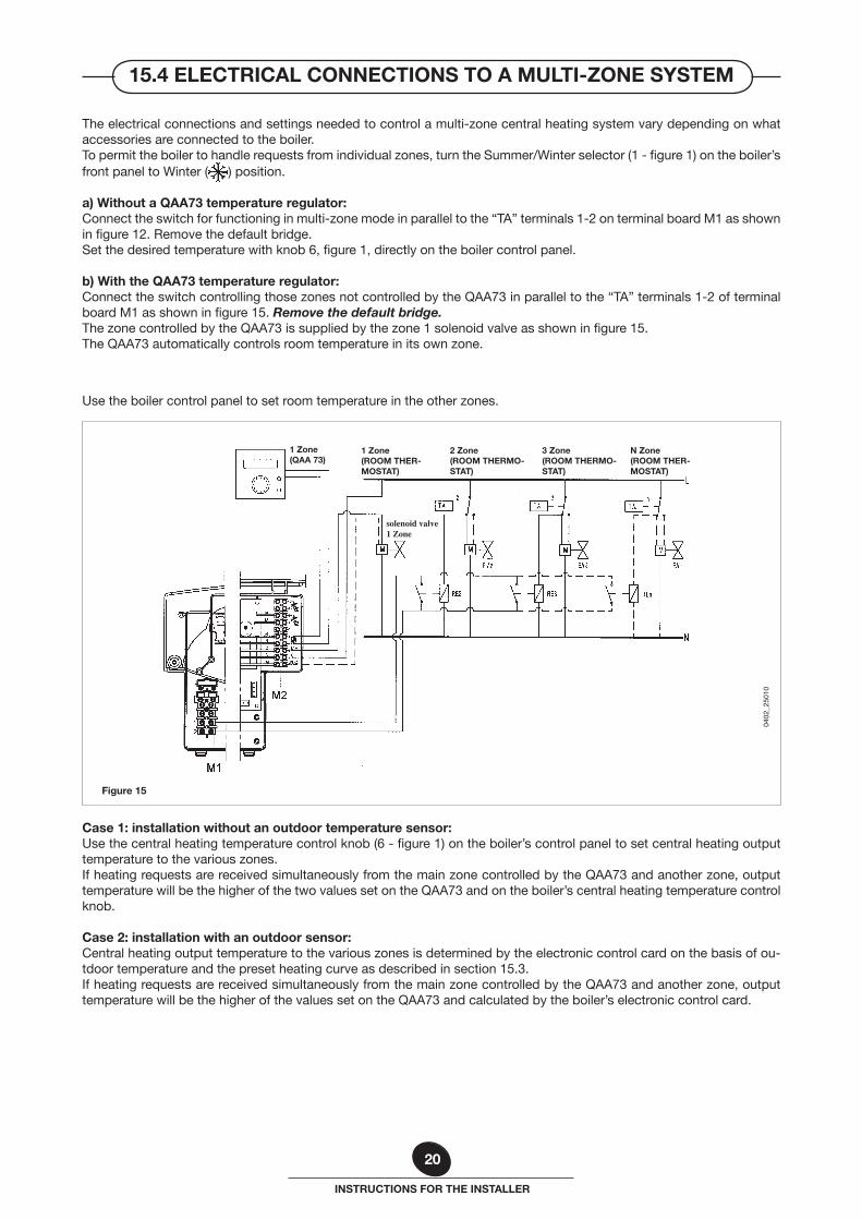
Figure 15
0402
_250
10
N Zone(ROOM THER-MOSTAT)
3 Zone(ROOM THERMO-STAT)
2 Zone(ROOM THERMO-STAT)
1 Zone(QAA 73)
solenoid valve 1 Zone
Case 1: installation without an outdoor temperature sensor:Use the central heating temperature control knob (6 - figure 1) on the boiler’s control panel to set central heating output temperature to the various zones.If heating requests are received simultaneously from the main zone controlled by the QAA73 and another zone, output temperature will be the higher of the two values set on the QAA73 and on the boiler’s central heating temperature control knob.
Case 2: installation with an outdoor sensor:Central heating output temperature to the various zones is determined by the electronic control card on the basis of ou-tdoor temperature and the preset heating curve as described in section 15.3.If heating requests are received simultaneously from the main zone controlled by the QAA73 and another zone, output temperature will be the higher of the values set on the QAA73 and calculated by the boiler’s electronic control card.
Use the boiler control panel to set room temperature in the other zones.
1 Zone(ROOM THER-MOSTAT)
The electrical connections and settings needed to control a multi-zone central heating system vary depending on what accessories are connected to the boiler.To permit the boiler to handle requests from individual zones, turn the Summer/Winter selector (1 - figure 1) on the boiler’s front panel to Winter ( ) position.
a) Without a QAA73 temperature regulator:Connect the switch for functioning in multi-zone mode in parallel to the “TA” terminals 1-2 on terminal board M1 as shown in figure 12. Remove the default bridge.Set the desired temperature with knob 6, figure 1, directly on the boiler control panel.
b) With the QAA73 temperature regulator:Connect the switch controlling those zones not controlled by the QAA73 in parallel to the “TA” terminals 1-2 of terminal board M1 as shown in figure 15. Remove the default bridge.The zone controlled by the QAA73 is supplied by the zone 1 solenoid valve as shown in figure 15.The QAA73 automatically controls room temperature in its own zone.
15.4 ELECTRICAL CONNECTIONS TO A MULTI-ZONE SYSTEM
21
INSTRUCTIONS FOR THE INSTALLER
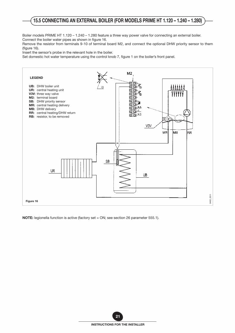
Boiler models PRIME HT 1.120 – 1.240 – 1.280 feature a three way power valve for connecting an external boiler.Connect the boiler water pipes as shown in figure 16.Remove the resistor from terminals 9-10 of terminal board M2, and connect the optional DHW priority sensor to them (figure 16).Insert the sensor’s probe in the relevant hole in the boiler.Set domestic hot water temperature using the control knob 7, figure 1 on the boiler’s front panel.
Figure 16
0402
_251
1
UB: DHW boiler unitUR: central heating unitV3V: three way valveM2: terminal boardSB: DHW priority sensorMR: central heating deliveryMB: DHW deliveryRR: central heating/DHW returnRB: resistor, to be removed
NOTE: legionella function is active (factory set = ON; see section 26 parameter 555.1).
15.5 CONNECTING AN EXTERNAL BOILER (FOR MODELS PRIME HT 1.120 – 1.240 – 1.280)
LEGEND
22
INSTRUCTIONS FOR THE INSTALLER
Proceed as follows to enter “calibration function” on the boiler control panel and calibrate the gas valve.
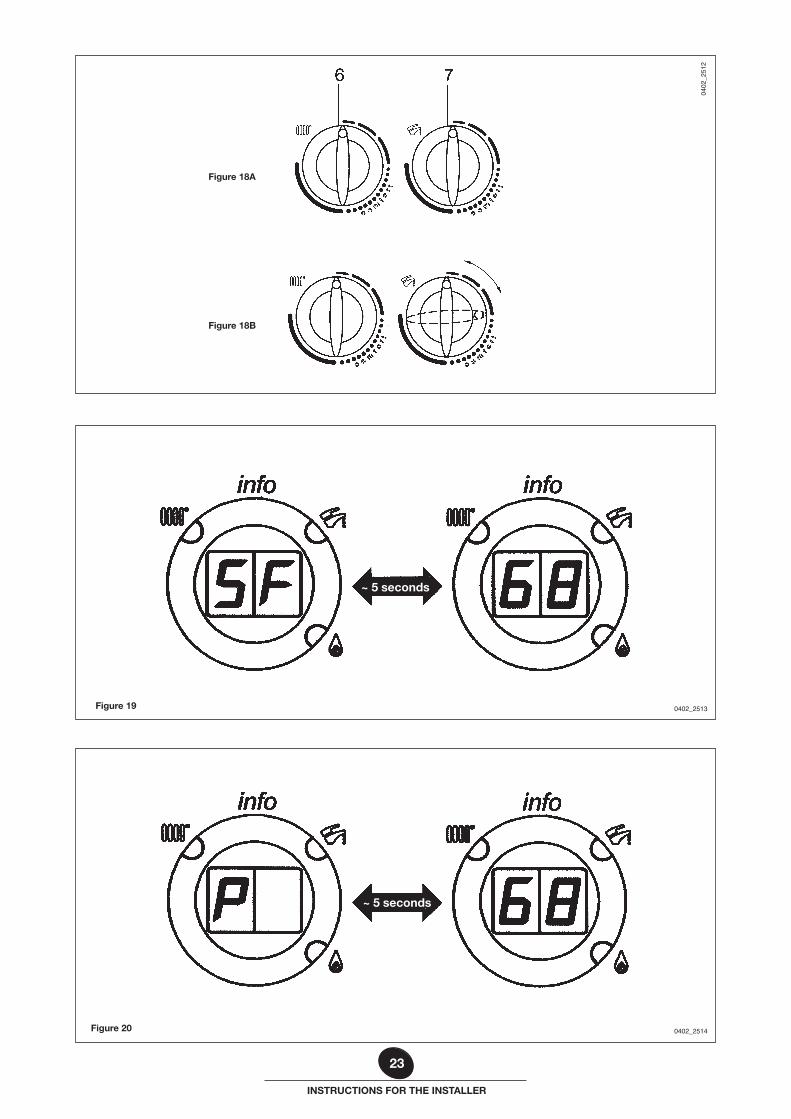
1) Turn the control knobs 6 and 7 (figure 1) fully anti-clockwise to their minimum positions as shown in figure 18A.2) Starting in this position, quickly turn control knob 7 twice consecutively clockwise through about a 1/4 turn as shown
in figure 18B.
NOTE: LEDs 2 and 3 (figure 1) flash alternately and the display alternates the message “SF” and the boiler output temperature about every five seconds (figure 19).
3) Now turn knob 6 to adjust fan speed to a setting between minimum thermal power (0%) and maximum thermal power (100%).
NOTE: In “calibration function”, the display alternates between the message “P” and the boiler output tempera-ture about every 5 seconds (figure 20).
4) Calibration function remains active for 20 minutes. To exit “calibration function” before this time simply turn control knob 7 (figure 1).
NOTE: This function is interrupted if the central heating delivery temperature reaches its MAX. SETPOINT.
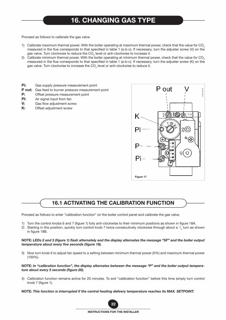
Proceed as follows to calibrate the gas valve.
1) Calibrate maximum thermal power. With the boiler operating at maximum thermal power, check that the value for CO2 measured in the flue corresponds to that specified in table 1 (a-b-c). If necessary, turn the adjuster screw (V) on the gas valve. Turn clockwise to reduce the CO2 level or anti-clockwise to increase it.
2) Calibrate minimum thermal power. With the boiler operating at minimum thermal power, check that the value for CO2 measured in the flue corresponds to that specified in table 1 (a-b-c). If necessary, turn the adjuster screw (K) on the gas valve. Turn clockwise to increase the CO2 level or anti-clockwise to reduce it.
0310
_011
4
Figure 17
Pi: Gas supply pressure measurement pointP out: Gas feed to burner pressure measurement pointP: Offset pressure measurement pointPl: Air signal input from fanV: Gas flow adjustment screwK: Offset adjustment screw
16.1 ACTIVATING THE CALIBRATION FUNCTION
16. CHANGING GAS TYPE
23
INSTRUCTIONS FOR THE INSTALLER
0402
_251
2
Figure 18B
Figure 19 0402_2513
~ 5 seconds
Figure 18A
Figure 20 0402_2514
~ 5 seconds
24
INSTRUCTIONS FOR THE INSTALLER
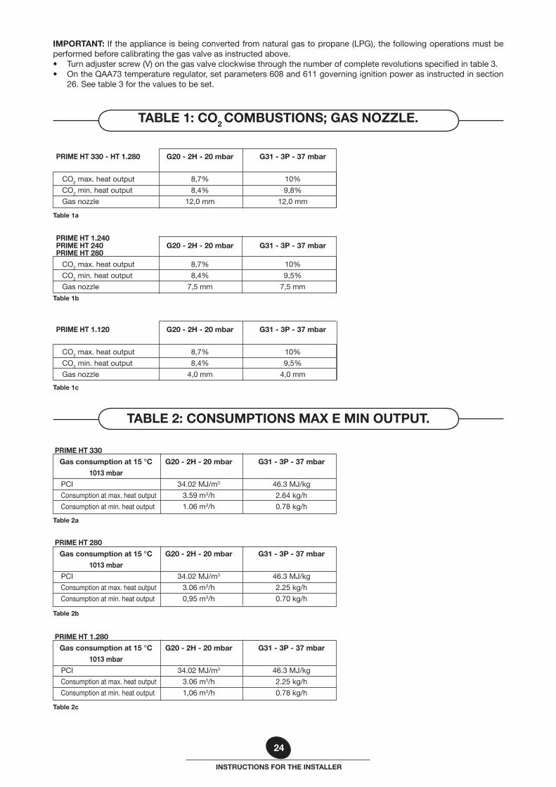
IMPORTANT: If the appliance is being converted from natural gas to propane (LPG), the following operations must be performed before calibrating the gas valve as instructed above.• Turn adjuster screw (V) on the gas valve clockwise through the number of complete revolutions specified in table 3.• On the QAA73 temperature regulator, set parameters 608 and 611 governing ignition power as instructed in section
26. See table 3 for the values to be set.
PRIME HT 1.240 PRIME HT 240 G20 - 2H - 20 mbar G31 - 3P - 37 mbar PRIME HT 280
CO2 max. heat output 8,7% 10%
CO2 min. heat output 8,4% 9,5%
Gas nozzle 7,5 mm 7,5 mm
PRIME HT 1.120 G20 - 2H - 20 mbar G31 - 3P - 37 mbar
CO2 max. heat output 8,7% 10%
CO2 min. heat output 8,4% 9,5%
Gas nozzle 4,0 mm 4,0 mm
Table 1c
Table 1b
PRIME HT 330 - HT 1.280 G20 - 2H - 20 mbar G31 - 3P - 37 mbar
CO2 max. heat output 8,7% 10%
CO2 min. heat output 8,4% 9,8%
Gas nozzle 12,0 mm 12,0 mm
Table 1a
PRIME HT 280
Gas consumption at 15 °C G20 - 2H - 20 mbar G31 - 3P - 37 mbar
1013 mbar
PCI 34.02 MJ/m3 46.3 MJ/kg
Consumption at max. heat output 3.06 m3/h 2.25 kg/h
Consumption at min. heat output 0,95 m3/h 0.70 kg/h
Table 2b
PRIME HT 330
Gas consumption at 15 °C G20 - 2H - 20 mbar G31 - 3P - 37 mbar
1013 mbar
PCI 34.02 MJ/m3 46.3 MJ/kg
Consumption at max. heat output 3.59 m3/h 2.64 kg/h
Consumption at min. heat output 1.06 m3/h 0.78 kg/h
Table 2a
PRIME HT 1.280
Gas consumption at 15 °C G20 - 2H - 20 mbar G31 - 3P - 37 mbar
1013 mbar
PCI 34.02 MJ/m3 46.3 MJ/kg
Consumption at max. heat output 3.06 m3/h 2.25 kg/h
Consumption at min. heat output 1,06 m3/h 0.78 kg/h
Table 2c
TABLE 1: CO2 COMBUSTIONS; GAS NOZZLE.
TABLE 2: CONSUMPTIONS MAX E MIN OUTPUT.
25
INSTRUCTIONS FOR THE INSTALLER
PRIME HT 240 - HT 1.240
Gas consumption at 15 °C G20 - 2H - 20 mbar G31 - 3P - 37 mbar
1013 mbar
PCI 34.02 MJ/m3 46.3 MJ/kg
Consumption at max. heat output 2.61 m3/h 1.92 kg/h
Consumption at min. heat output 0.74 m3/h 0.54 kg/h
Table 2d
PRIME HT 1.120
Gas consumption at 15 °C G20 - 2H - 20 mbar G31 - 3P - 37 mbar
1013 mbar
PCI 34.02 MJ/m3 46.3 MJ/kg
Consumption at max. heat output 1.31 m3/h 0.96 kg/h
Consumption at min. heat output 0,42 m3/h 0,31 kg/h
Table 2e
Counter clockwise Parameter 608 Parameter 611 Boiler model turns of screw % rpm
(V) Gas G20 Gas G31 Gas G20 Gas G31
PRIME HT 330 3 50 35 4100 3500
PRIME HT 280 4 55 35 4400 4000
PRIME HT 240 2 50 35 4300 4000
PRIME HT 1.280 3 50 35 4100 3500
PRIME HT 1.240 2 55 35 4500 4000
PRIME HT 1.120 3/4 40 40 4000 3350
Table 3
TABLE 3: SETTING PARAMETRES 608 AND 611
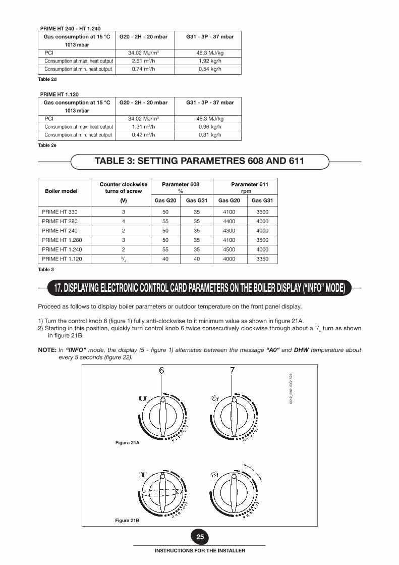
Proceed as follows to display boiler parameters or outdoor temperature on the front panel display.
1) Turn the control knob 6 (figure 1) fully anti-clockwise to it minimum value as shown in figure 21A.2) Starting in this position, quickly turn control knob 6 twice consecutively clockwise through about a 1/4 turn as shown
in figure 21B.
NOTE: In “INFO” mode, the display (5 - figure 1) alternates between the message “A0” and DHW temperature about every 5 seconds (figure 22).
17. DISPLAYING ELECTRONIC CONTROL CARD PARAMETERS ON THE BOILER DISPLAY (“INFO” MODE)
Figura 21B
0512
_080
1/C
G15
23
Figura 21A
26
INSTRUCTIONS FOR THE INSTALLER
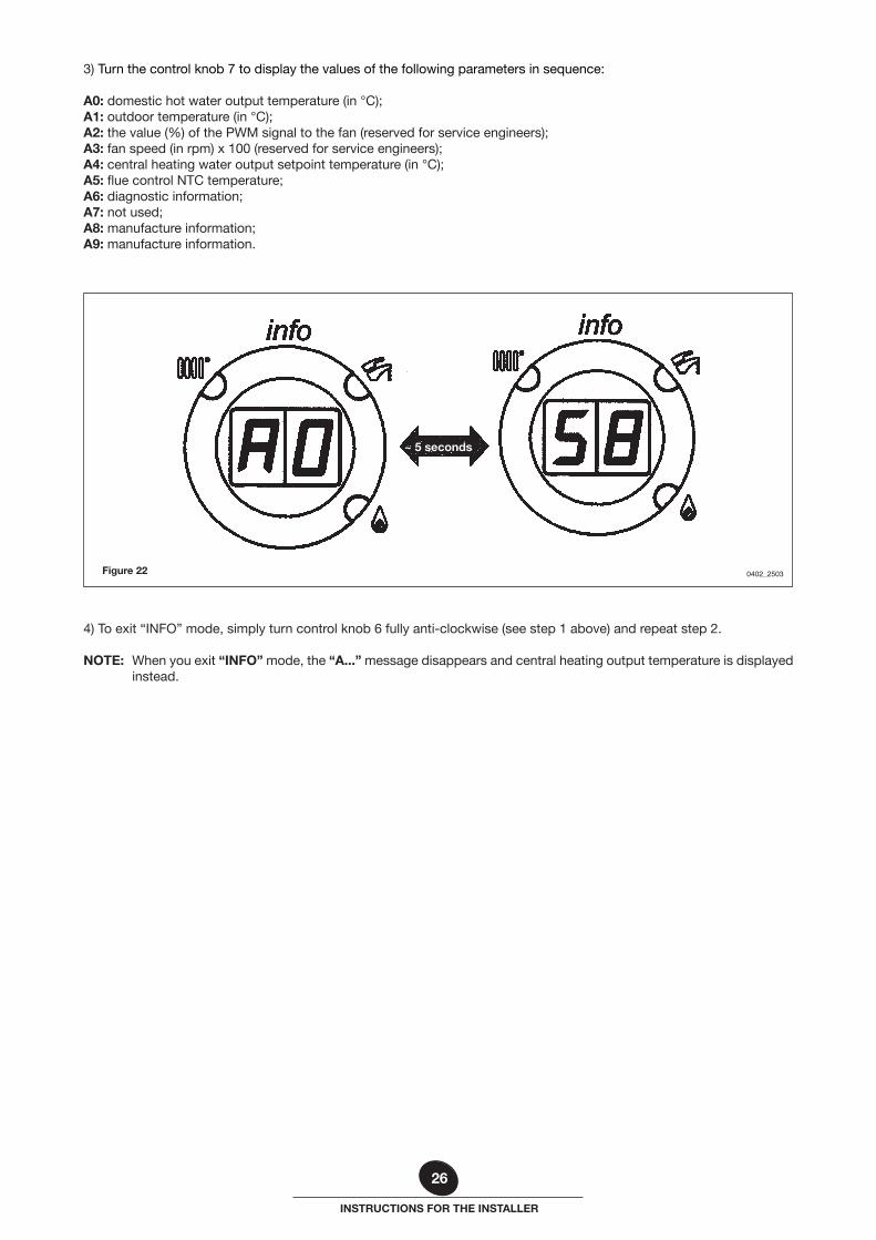
3) Turn the control knob 7 to display the values of the following parameters in sequence:
A0: domestic hot water output temperature (in °C);A1: outdoor temperature (in °C);A2: the value (%) of the PWM signal to the fan (reserved for service engineers);A3: fan speed (in rpm) x 100 (reserved for service engineers);A4: central heating water output setpoint temperature (in °C);A5: flue control NTC temperature;A6: diagnostic information;A7: not used;A8: manufacture information;A9: manufacture information.
Figure 22 0402_2503
~ 5 seconds
4) To exit “INFO” mode, simply turn control knob 6 fully anti-clockwise (see step 1 above) and repeat step 2.
NOTE: When you exit “INFO” mode, the “A...” message disappears and central heating output temperature is displayed instead.
27
INSTRUCTIONS FOR THE INSTALLER
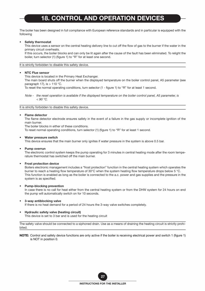
The boiler has been designed in full compliance with European reference standards and in particular is equipped with the following
• Safety thermostat This device uses a sensor on the central heating delivery line to cut off the flow of gas to the burner if the water in the
primary circuit overheats. If this occurs, the boiler blocks and can only be lit again after the cause of the fault has been eliminated. To relight the
boiler, turn selector (1) (figure 1) to “R” for at least one second.
It is strictly forbidden to disable this safety device.
• NTC Flue sensor This device is located in the Primary Heat Exchanger. The main board shuts off the burner when the displayed temperature on the boiler control panel, A5 parameter (see
paragraph 17), is > 110 °C. To reset the normal operating conditions, turn selector (1 - figure 1) to “R” for at least 1 second.
Note - the reset operation is available if the displayed temperature on the boiler control panel, A5 parameter, is < 90 °C.
It is strictly forbidden to disable this safety device.
• Flame detector The flame detector electrode ensures safety in the event of a failure in the gas supply or incomplete ignition of the
main burner. The boiler blocks in either of these conditions. To reset normal operating conditions, turn selector (1) (figure 1) to “R” for at least 1 second.
• Water pressure switch This device ensures that the main burner only ignites if water pressure in the system is above 0.5 bar.
• Pump overrun The electronic control system keeps the pump operating for 3 minutes in central heating mode after the room tempe-
rature thermostat has switched off the main burner.
• Frost protection device Boilers electronic management includes a “frost protection” function in the central heating system which operates the
burner to reach a heating flow temperature of 30°C when the system heating flow temperature drops below 5 °C. This function is enabled as long as the boiler is connected to the a.c. power and gas supplies and the pressure in the
system is as specified.
• Pump-blocking prevention In case there is no call for heat either from the central heating system or from the DHW system for 24 hours on end
the pump will automatically switch on for 10 seconds.
• 3-way antiblocking valve If there is no heat demand for a period of 24 hours the 3-way valve switches completely.
• Hydraulic safety valve (heating circuit) This device is set to 3 bar and is used for the heating circuit
The safety valve should be connected to a siphoned drain. Use as a means of draining the heating circuit is strictly prohi-bited.
NOTE: Control and safety device functions are only active if the boiler is receiving electrical power and switch 1 (figure 1) is NOT in position 0.
18. CONTROL AND OPERATION DEVICES
28
INSTRUCTIONS FOR THE INSTALLER
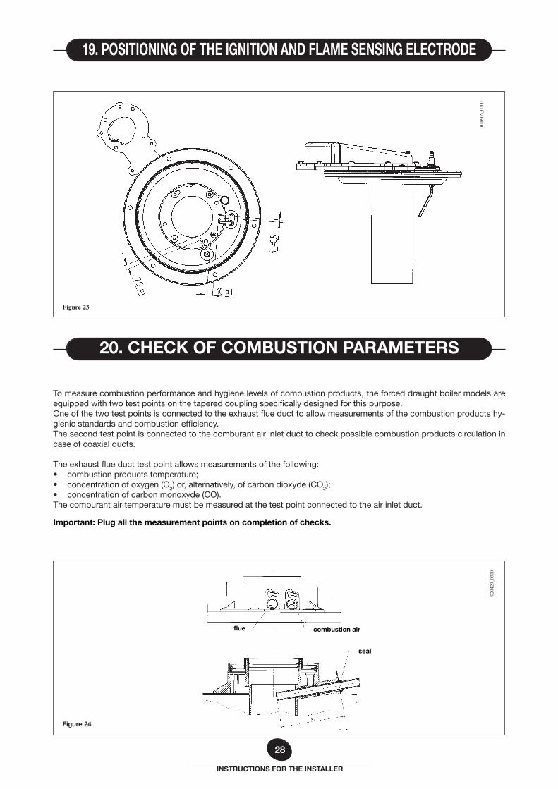
To measure combustion performance and hygiene levels of combustion products, the forced draught boiler models are equipped with two test points on the tapered coupling specifically designed for this purpose.One of the two test points is connected to the exhaust flue duct to allow measurements of the combustion products hy-gienic standards and combustion efficiency.The second test point is connected to the comburant air inlet duct to check possible combustion products circulation in case of coaxial ducts.
The exhaust flue duct test point allows measurements of the following:• combustion products temperature;• concentration of oxygen (O2) or, alternatively, of carbon dioxyde (CO2);• concentration of carbon monoxyde (CO).The comburant air temperature must be measured at the test point connected to the air inlet duct.
Important: Plug all the measurement points on completion of checks.
Figure 24
0204
29_0
300
flue combustion air
seal
Figure 23
0109
05_0
200
19. POSITIONING OF THE IGNITION AND FLAME SENSING ELECTRODE
20. CHECK OF COMBUSTION PARAMETERS
29
INSTRUCTIONS FOR THE INSTALLER
Proceed as follows to activate the flue sweep function before measuring combustion efficiency and fume composition.1) Turn knobs 6 and 7 (figure 1) fully anti-clockwise to their minimum positions as shown in figure 18A.2) Starting in this position, quickly turn control knob 7 twice consecutively clockwise through about 1/4 of a turn as shown
in figure 18B.
NOTE: In FLUE SWEEP mode, LEDs 2 and 3 (figure 1) flash alternately and the display alternates the message “SF” and the boiler output temperature about every five seconds (figure 19).
IMPORTANT: In FLUE SWEEP mode, do not turn knob 6 from its initial position or you will enter “calibration” mode in-stead (see section 16.1).
3) Flue sweep mode remains active for 20 minutes. To exit FLUE SWEEP mode before this time, simply turn knob 7 (figure 1). The function also stops if the central heating MAX. SETPOINT temperature is reached (see section 16.1 point 4).
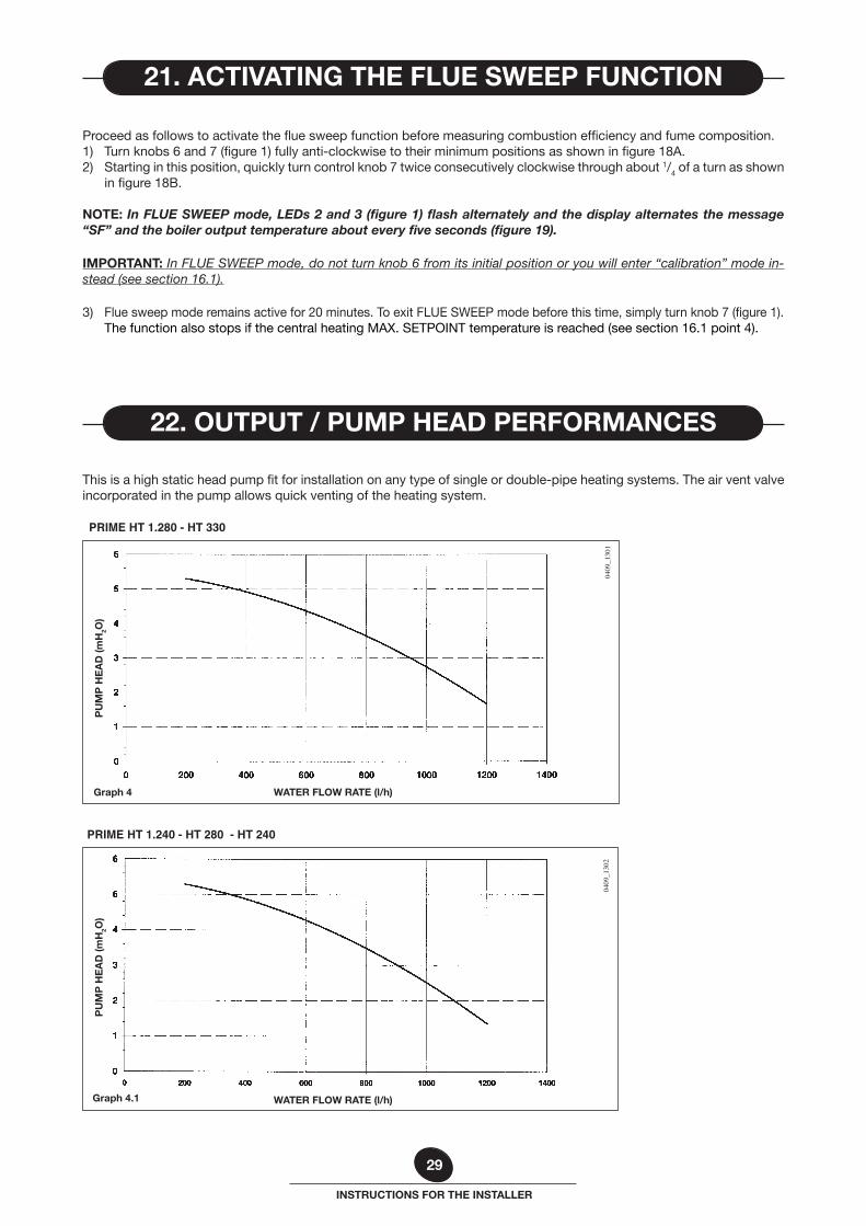
This is a high static head pump fit for installation on any type of single or double-pipe heating systems. The air vent valve incorporated in the pump allows quick venting of the heating system.
PU
MP
HE
AD
(mH
2O)
WATER FLOW RATE (l/h)Graph 4
Graph 4.1
21. ACTIVATING THE FLUE SWEEP FUNCTION
22. OUTPUT / PUMP HEAD PERFORMANCES
0409
_130
104
09_1
302
PRIME HT 1.280 - HT 330
PRIME HT 1.240 - HT 280 - HT 240
PU
MP
HE
AD
(mH
2O)
WATER FLOW RATE (l/h)
30
INSTRUCTIONS FOR THE INSTALLER
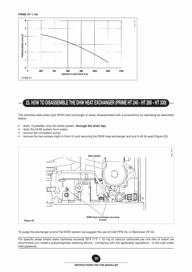
The stainless steel plate-type DHW heat exchanger is easily disassembled with a screwdriver by operating as described below:
• drain, if possible, only the boiler system, through the drain tap;• drain the DHW system from water;• remove the circulation pump;• remove the two screws (right in front of you) securing the DHW heat exchanger and pull it off its seat (Figure 25).
Figure 25
DHW heat exchanger securing screws
flow sensor 0402
_251
5
To purge the exchanger and/or the DHW system we suggest the use of Cillit FFW-AL or Beckinser HF-AL.
For specific areas where water hardness exceeds 20°F (1°F = 10 mg of calcium carbonate per one litre of water) we recommend you install a polyphosphate metering device - complying with the applicable regulations - in the cold water inlet pipework.
23. HOW TO DISASSEMBLE THE DHW HEAT EXCHANGER (PRIME HT 240 - HT 280 - HT 330)
WATER FLOW RATE (l/h)
Graph 4.2
PR
EVA
LEN
ZA
(mH
2O)
0409
_130
3
PRIME HT 1.120
31
INSTRUCTIONS FOR THE INSTALLER
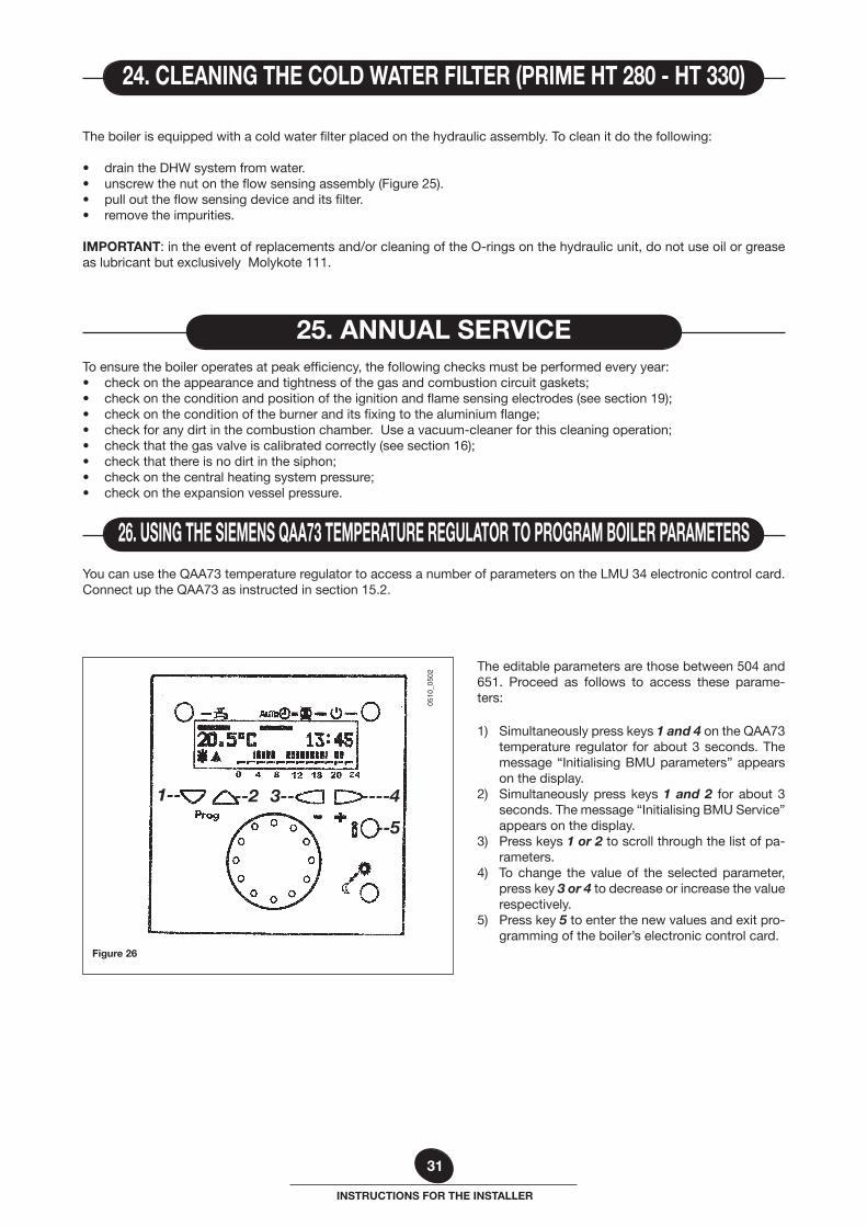
The editable parameters are those between 504 and 651. Proceed as follows to access these parame-ters:
1) Simultaneously press keys 1 and 4 on the QAA73 temperature regulator for about 3 seconds. The message “Initialising BMU parameters” appears on the display.
2) Simultaneously press keys 1 and 2 for about 3 seconds. The message “Initialising BMU Service” appears on the display.
3) Press keys 1 or 2 to scroll through the list of pa-rameters.
4) To change the value of the selected parameter, press key 3 or 4 to decrease or increase the value respectively.
5) Press key 5 to enter the new values and exit pro-gramming of the boiler’s electronic control card.
You can use the QAA73 temperature regulator to access a number of parameters on the LMU 34 electronic control card. Connect up the QAA73 as instructed in section 15.2.
Figure 26
26. USING THE SIEMENS QAA73 TEMPERATURE REGULATOR TO PROGRAM BOILER PARAMETERS
To ensure the boiler operates at peak efficiency, the following checks must be performed every year:• check on the appearance and tightness of the gas and combustion circuit gaskets;• check on the condition and position of the ignition and flame sensing electrodes (see section 19);• check on the condition of the burner and its fixing to the aluminium flange;• check for any dirt in the combustion chamber. Use a vacuum-cleaner for this cleaning operation;• check that the gas valve is calibrated correctly (see section 16);• check that there is no dirt in the siphon;• check on the central heating system pressure;• check on the expansion vessel pressure.
25. ANNUAL SERVICE
The boiler is equipped with a cold water filter placed on the hydraulic assembly. To clean it do the following:
• drain the DHW system from water.• unscrew the nut on the flow sensing assembly (Figure 25).• pull out the flow sensing device and its filter.• remove the impurities.
IMPORTANT: in the event of replacements and/or cleaning of the O-rings on the hydraulic unit, do not use oil or grease as lubricant but exclusively Molykote 111.
24. CLEANING THE COLD WATER FILTER (PRIME HT 280 - HT 330)
0510
_050
2
1-- 3----2 ----4
--5
32
INSTRUCTIONS FOR THE INSTALLER
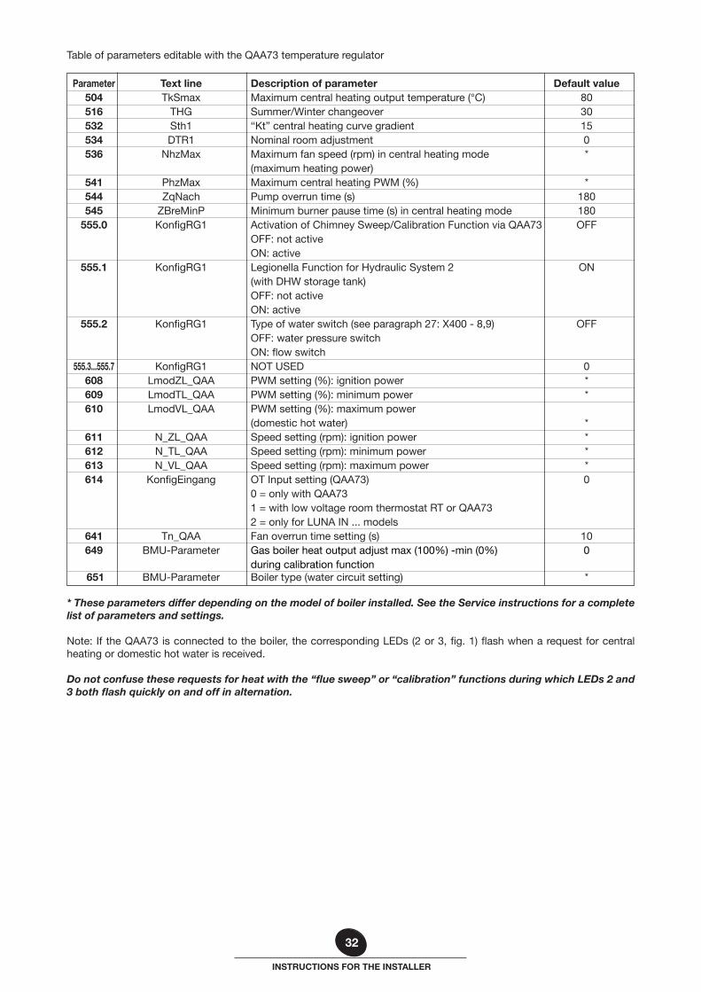
* These parameters differ depending on the model of boiler installed. See the Service instructions for a complete list of parameters and settings.
Note: If the QAA73 is connected to the boiler, the corresponding LEDs (2 or 3, fig. 1) flash when a request for central heating or domestic hot water is received.
Do not confuse these requests for heat with the “flue sweep” or “calibration” functions during which LEDs 2 and 3 both flash quickly on and off in alternation.
Table of parameters editable with the QAA73 temperature regulator
Parameter Text line Description of parameter Default value 504 TkSmax Maximum central heating output temperature (°C) 80 516 THG Summer/Winter changeover 30 532 Sth1 “Kt” central heating curve gradient 15 534 DTR1 Nominal room adjustment 0 536 NhzMax Maximum fan speed (rpm) in central heating mode * (maximum heating power) 541 PhzMax Maximum central heating PWM (%) * 544 ZqNach Pump overrun time (s) 180 545 ZBreMinP Minimum burner pause time (s) in central heating mode 180 555.0 KonfigRG1 Activation of Chimney Sweep/Calibration Function via QAA73 OFF OFF: not active ON: active 555.1 KonfigRG1 Legionella Function for Hydraulic System 2 ON (with DHW storage tank) OFF: not active ON: active 555.2 KonfigRG1 Type of water switch (see paragraph 27: X400 - 8,9) OFF OFF: water pressure switch ON: flow switch 555.3...555.7 KonfigRG1 NOT USED 0 608 LmodZL_QAA PWM setting (%): ignition power * 609 LmodTL_QAA PWM setting (%): minimum power * 610 LmodVL_QAA PWM setting (%): maximum power (domestic hot water) * 611 N_ZL_QAA Speed setting (rpm): ignition power * 612 N_TL_QAA Speed setting (rpm): minimum power * 613 N_VL_QAA Speed setting (rpm): maximum power * 614 KonfigEingang OT Input setting (QAA73) 0 0 = only with QAA73 1 = with low voltage room thermostat RT or QAA73 2 = only for LUNA IN ... models 641 Tn_QAA Fan overrun time setting (s) 10 649 BMU-Parameter Gas boiler heat output adjust max (100%) -min (0%) 0 during calibration function 651 BMU-Parameter Boiler type (water circuit setting) *
33
INSTRUCTIONS FOR THE INSTALLER
Figure 27
0402
_251
6
heating domestic water gas domestic water heating inlet outlet inlet return
SEALED CHAMBER
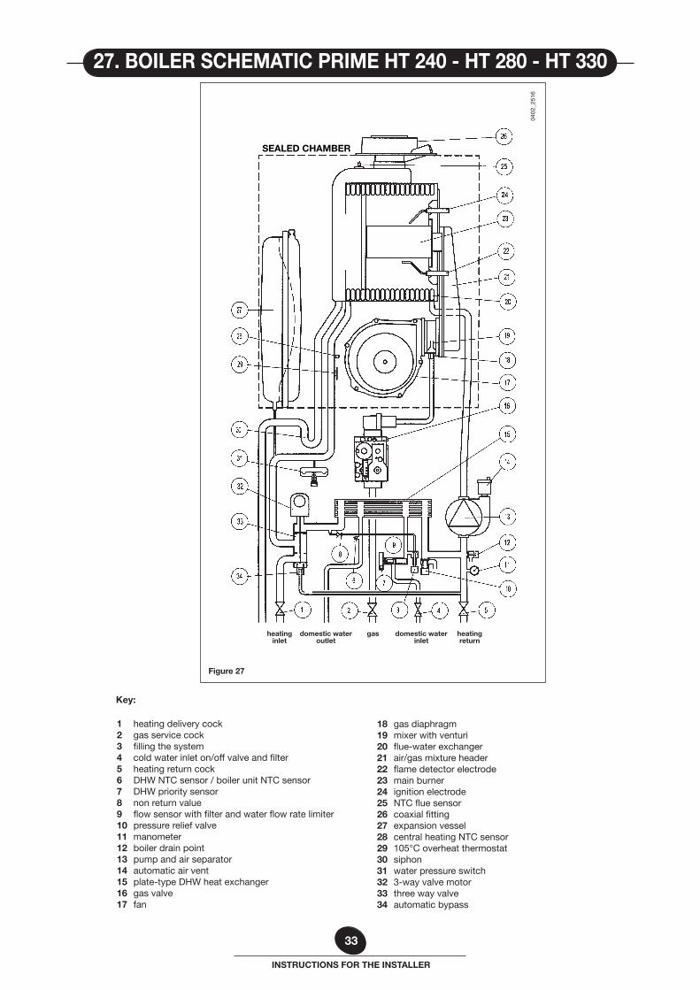
1 heating delivery cock2 gas service cock3 filling the system4 cold water inlet on/off valve and filter5 heating return cock6 DHW NTC sensor / boiler unit NTC sensor7 DHW priority sensor8 non return value9 flow sensor with filter and water flow rate limiter10 pressure relief valve11 manometer12 boiler drain point13 pump and air separator14 automatic air vent15 plate-type DHW heat exchanger16 gas valve17 fan
18 gas diaphragm19 mixer with venturi20 flue-water exchanger21 air/gas mixture header22 flame detector electrode23 main burner24 ignition electrode25 NTC flue sensor26 coaxial fitting27 expansion vessel28 central heating NTC sensor29 105°C overheat thermostat30 siphon31 water pressure switch32 3-way valve motor33 three way valve34 automatic bypass
27. BOILER SCHEMATIC PRIME HT 240 - HT 280 - HT 330
Key:
34
INSTRUCTIONS FOR THE INSTALLER
Figure 28
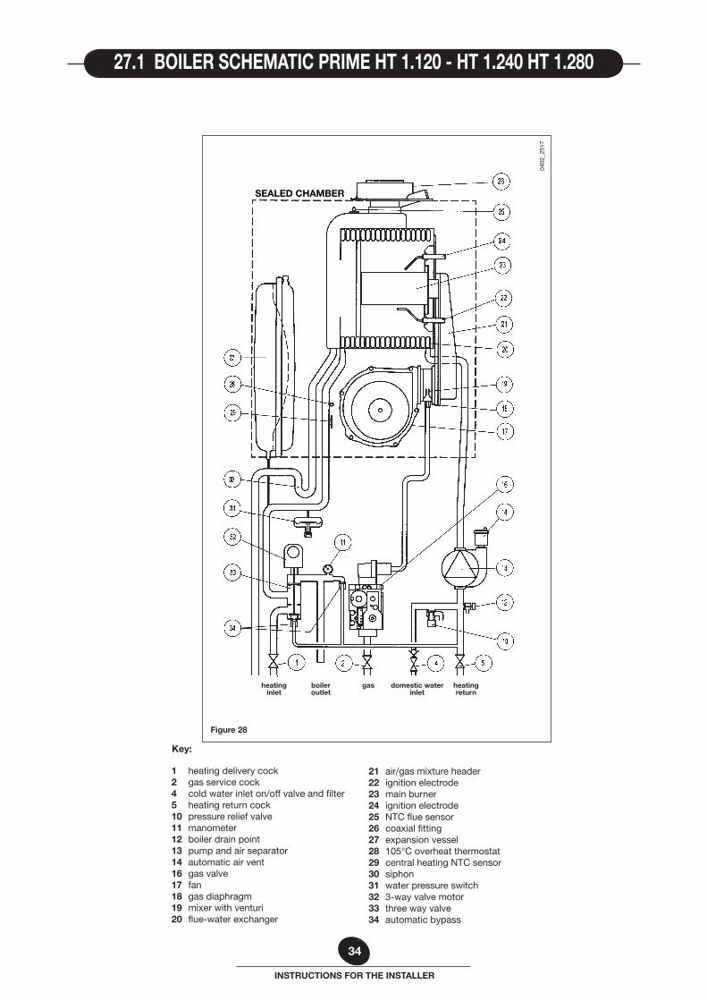
heating boiler gas domestic water heating inlet outlet inlet return
1 heating delivery cock2 gas service cock4 cold water inlet on/off valve and filter5 heating return cock10 pressure relief valve11 manometer12 boiler drain point13 pump and air separator14 automatic air vent16 gas valve17 fan18 gas diaphragm19 mixer with venturi20 flue-water exchanger
21 air/gas mixture header22 ignition electrode23 main burner24 ignition electrode25 NTC flue sensor26 coaxial fitting27 expansion vessel28 105°C overheat thermostat29 central heating NTC sensor30 siphon31 water pressure switch32 3-way valve motor33 three way valve34 automatic bypass
0402
_251
7
SEALED CHAMBER
27.1 BOILER SCHEMATIC PRIME HT 1.120 - HT 1.240 HT 1.280
Key:
35
INSTRUCTIONS FOR THE INSTALLER
FAN
MA
INS
PO
WER
230
V
FUSE
S
MA
INS
POW
ER T
ERM
INA
L BO
ARD
SAFE
TY
THER
MO
STAT
FLA
ME
DET
ECTI
ON
EL
ECTR
OD
E
GA
S VA
LVE
CENT
RAL
HEAT
ING
NTC
SENS
OR
230
V R
OO
M T
EMPE
RAT
UR
E
THER
MO
STAT
PROV
ISION
FOR
OUTD
OOR T
EMPE
RATU
RE SE
NSOR
IGN
ITER IG
NIT
ION
EL
ECTR
OD
E
WAT
ER P
RES
SUR
E SW
ITC
H
DO
MES
TIC
HO
T W
ATER
NTC
SEN
SOR
THR
EE W
AY V
ALV
E
CEN
TRA
L H
EATI
NG
PR
OG
RA
MM
ER
PUM
P
BO
ILER
FR
AM
E
EART
H T
ERM
INA
L B
OA
RD
Sum
mer
/Win
ter S
ELEC
TOR
- RES
ET
DO
MES
TIC
HO
T W
ATER
PR
IOR
ITY
SEN
SOR
CA
BLE
S C
OLO
UR
S
C
=
light
blu
e
M =
br
own
N
=
blac
k
R =
re
d G
/V =
ye
llow
/gre
en
B =
w
hite
G
=
yello
w
FLU
E SE
NSO
R
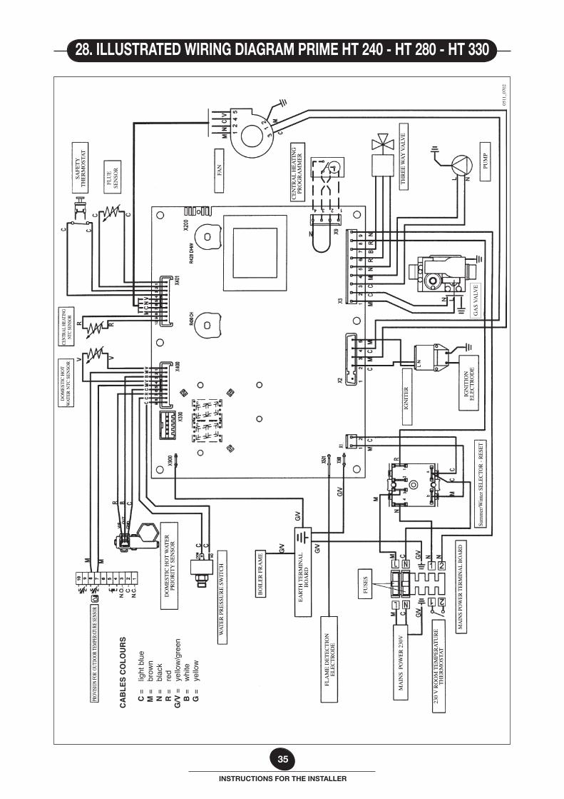
28. ILLUSTRATED WIRING DIAGRAM PRIME HT 240 - HT 280 - HT 330
0511
_070
2
36
INSTRUCTIONS FOR THE INSTALLER
FAN
MA
INS
PO
WER
230
V
FUSE
S
MA
INS
POW
ER T
ERM
INA
L BO
ARD
SAFE
TY
THER
MO
STAT
IGN
ITER
IGN
ITIO
N
ELEC
TRO
DE
WAT
ER P
RES
SUR
E SW
ITC
H
PRO
VIS
ION
FO
R D
HW
PR
IOR
ITY
NTC
SEN
SOR
THR
EE W
AY V
ALV
E
CEN
TRA
L H
EATI
NG
PR
OG
RA
MM
ER
PUM
P
BO
ILER
FR
AM
E
EART
H T
ERM
INA
L B
OA
RD
Sum
mer
/Win
ter S
ELEC
TOR
- RES
ET
CA
BLE
S C
OLO
UR
S
C
=
light
blu
e
M =
br
own
N
=
blac
k
R =
re
d G
/V =
ye
llow
/gre
en
B =
w
hite
G
=
yello
w
PROV
ISION
FOR
OUTD
OOR T
EMPE
RATU
RE SE
NSOR
FLA
ME
DET
ECTI
ON
EL
ECTR
OD
E
230
V R
OO
M T
EMPE
RAT
UR
E
THER
MO
STAT
CENT
RAL H
EATI
NG
NTC
SENS
OR
FLU
E SE
NSO
R
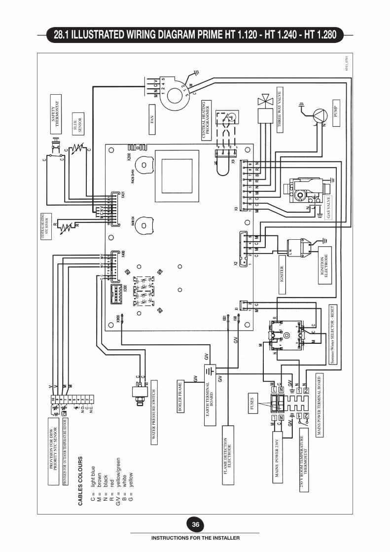
28.1 ILLUSTRATED WIRING DIAGRAM PRIME HT 1.120 - HT 1.240 - HT 1.280
GA
S VA
LVE
0511
_070
1

37
INSTRUCTIONS FOR THE INSTALLER

38
INSTRUCTIONS FOR THE INSTALLER

39
INSTRUCTIONS FOR THE INSTALLER
codice C604715.2
BAXI S.p.A is constantly striving to improve its products and therefore reserves the right to modify the data contained in this document at any time and without prior notice. This document is provided for information purposes only and cannot be considered contractually binding.
BAXI S.p.A.36061 BASSANO DEL GRAPPA (VI) ITALIA
Via Trozzetti, 20Tel. 0424 - 517111
Telefax 0424/38089
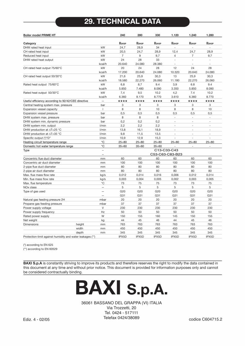
Boiler model PRIME HT 240 280 330 1.120 1.240 1.280
Category II2H3P II2H3P II2H3P II2H3P II2H3P II2H3P
DHW rated heat input kW 24,7 28,9 34 - - -CH rated heat input kW 20,5 24,7 28,9 12,4 24,7 28,9Reduced heat input kW 7 9 9,7 4 7 9,7DHW rated heat output kW 24 28 33 - - - kcal/h 20.640 24.080 28.380 - - -CH rated heat output 75/60°C kW 20 24 28 12 24 28 kcal/h 17.200 20.640 24.080 10.320 20.640 24.080CH rated heat output 50/30°C kW 21,6 25,9 30,3 13 25,9 30,3 kcal/h 18.580 22.270 26.060 11.180 22.270 26.060Rated heat output 75/60°C kW 6,8 8,7 9.4 3,9 6.8 9.4 kcal/h 5.850 7.480 8.090 3.350 5.850 8.090Rated heat output 50/30°C kW 7,4 9,5 10.2 4,2 7.4 10.2 kcal/h 6.360 8.170 8.770 3.610 6.360 8.770Useful efficiency according to 92/42/CEE directive — ★★★★ ★★★★ ★★★★ ★★★★ ★★★★ ★★★★
Central heating system max. pressure bar 3 3 3 3 3 3Expansion vessel capacity l 8 8 10 8 8 10Expansion vessel pressure bar 0,5 0,5 0,5 0,5 0,5 0,5DHW system max. pressure bar 8 8 8 - - -DHW system min. dynamic pressure bar 0,2 0,2 0,2 - - -DHW system min. output l/min 2,2 2,2 2,2 - - -DHW production at ∆T=25 °C l/min 13,8 16,1 18,9 - - -DHW production at ∆T=35 °C l/min 9,8 11,5 13,5 - - -Specific output (*)“D” l/min 10,9 12,9 15,3 - - -Heating circuit temperature range °C 25÷80 25÷80 25÷80 25÷80 25÷80 25÷80Domestic hot water temperature range °C 35÷60 35÷60 35÷60 - - -Type — C13-C33-C43 — C53-C63-C83-B23Concentric flue duct diameter mm 60 60 60 60 60 60Concentric air duct diameter mm 100 100 100 100 100 1002-pipe flue duct diameter mm 80 80 80 80 80 802-pipe air duct diameter mm 80 80 80 80 80 80Max. flue mass flow rate kg/s 0,012 0,014 0,016 0,006 0,012 0,014Min. flue mass flow rate kg/s 0,003 0,004 0,005 0,002 0,003 0,005Max. flue temperature °C 73 75 75 73 73 75NOx class — 5 5 5 5 5 5Type of gas used — G20 G20 G20 G20 G20 G20 — G31 G31 G31 G31 G31 G31Natural gas feeding pressure 2H mbar 20 20 20 20 20 20Propane gas feeding pressure mbar 37 37 37 37 37 37Power supply voltage V 230 230 230 230 230 230Power supply frequency Hz 50 50 50 50 50 50Rated power supply W 150 155 160 145 150 155Net weight kg 44 45 46 44 45 46Dimensions height mm 763 763 763 763 763 763 width mm 450 450 450 450 450 450 depth mm 345 345 345 345 345 345Protection-limit against humidity and water leakages (**) IPX5D IPX5D IPX5D IPX5D IPX5D IPX5D (*) according to EN 625 (**) according to EN 60529
Ediz. 4 - 02/05
29. TECHNICAL DATA