
Primary goal of a MN is to achieve Γinekim/e194rfs01/lec20ek.pdfRegion of matching for series C...
22
EEE 194RF_L20 1 Matching Networks • MNs are critical for at least two critical reasons – maximize power transfer: – minimize • Primary goal of a MN is to achieve 0 = Γ in ) | | 1 ( 2 in i r i t P P P P Γ - = - = | | 1 | | 1 in in SWR Γ - Γ =
Transcript of Primary goal of a MN is to achieve Γinekim/e194rfs01/lec20ek.pdfRegion of matching for series C...
EEE 194RF_L20 1
Matching Networks
• MNs are critical for at least two critical reasons– maximize power transfer: – minimize
• Primary goal of a MN is to achieve
0=Γin
)||1( 2inirit PPPP Γ−=−=
||1||1
in
inSWRΓ−Γ+
=
EEE 194RF_L20 2
Matching Strategy
• Pick an appropriate two-element MN for which matching is possible (based on a given load impedance or S-parameter)
• Find the L, C values from the ZY Smith Chart
• Convert discrete values into equivalent microstriplines
EEE 194RF_L20 3
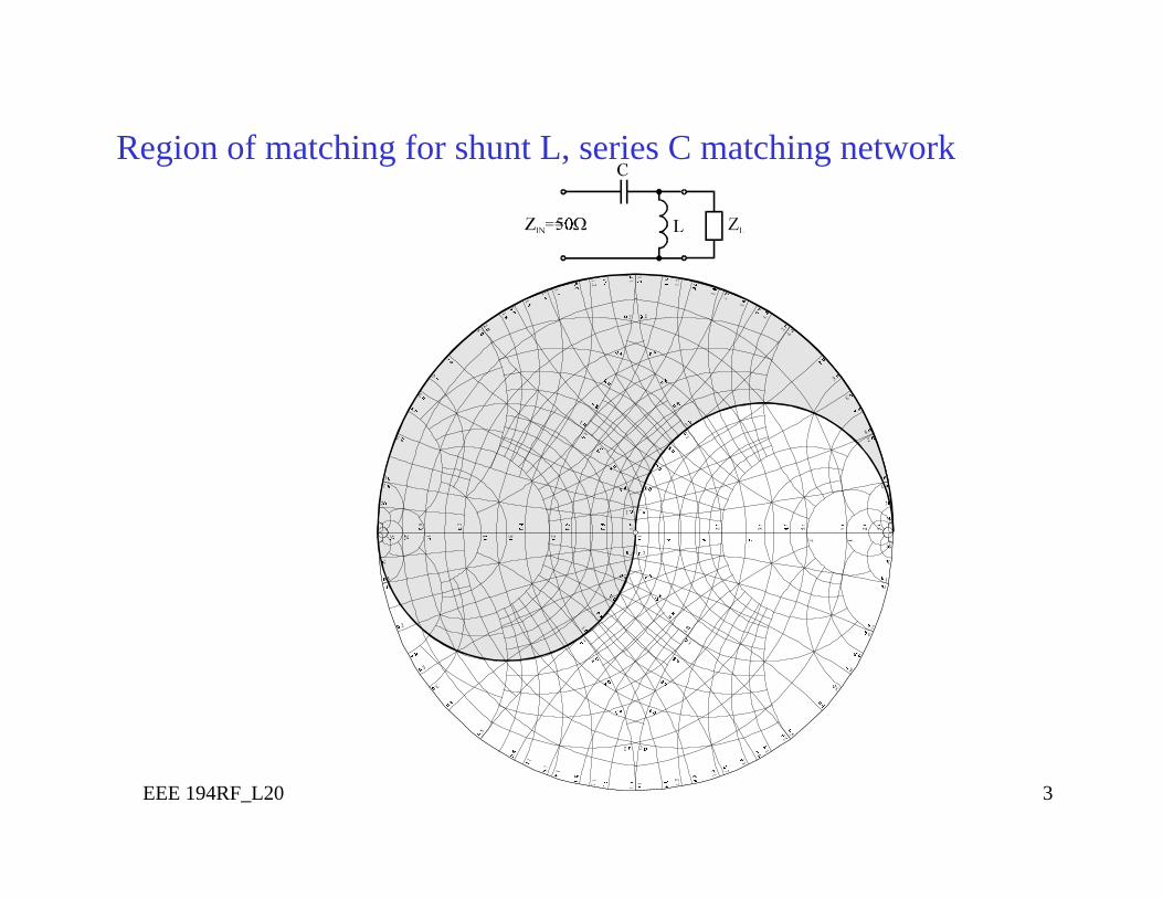
Region of matching for shunt L, series C matching network
EEE 194RF_L20 4
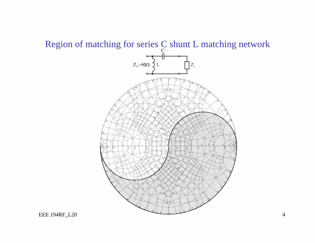
Region of matching for series C shunt L matching network
EEE 194RF_L20 5
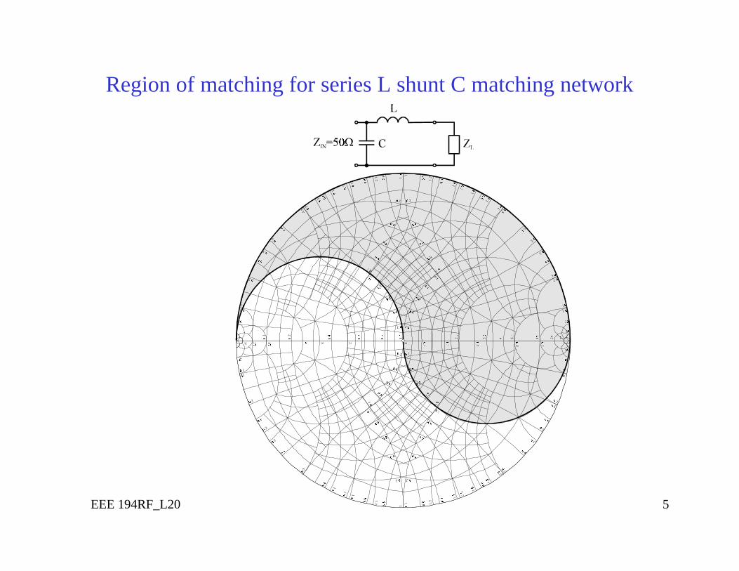
Region of matching for series L shunt C matching network
EEE 194RF_L20 6
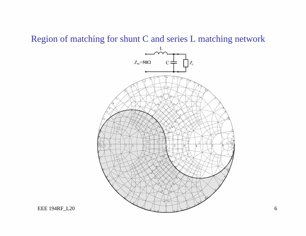
Region of matching for shunt C and series L matching network
EEE 194RF_L20 7
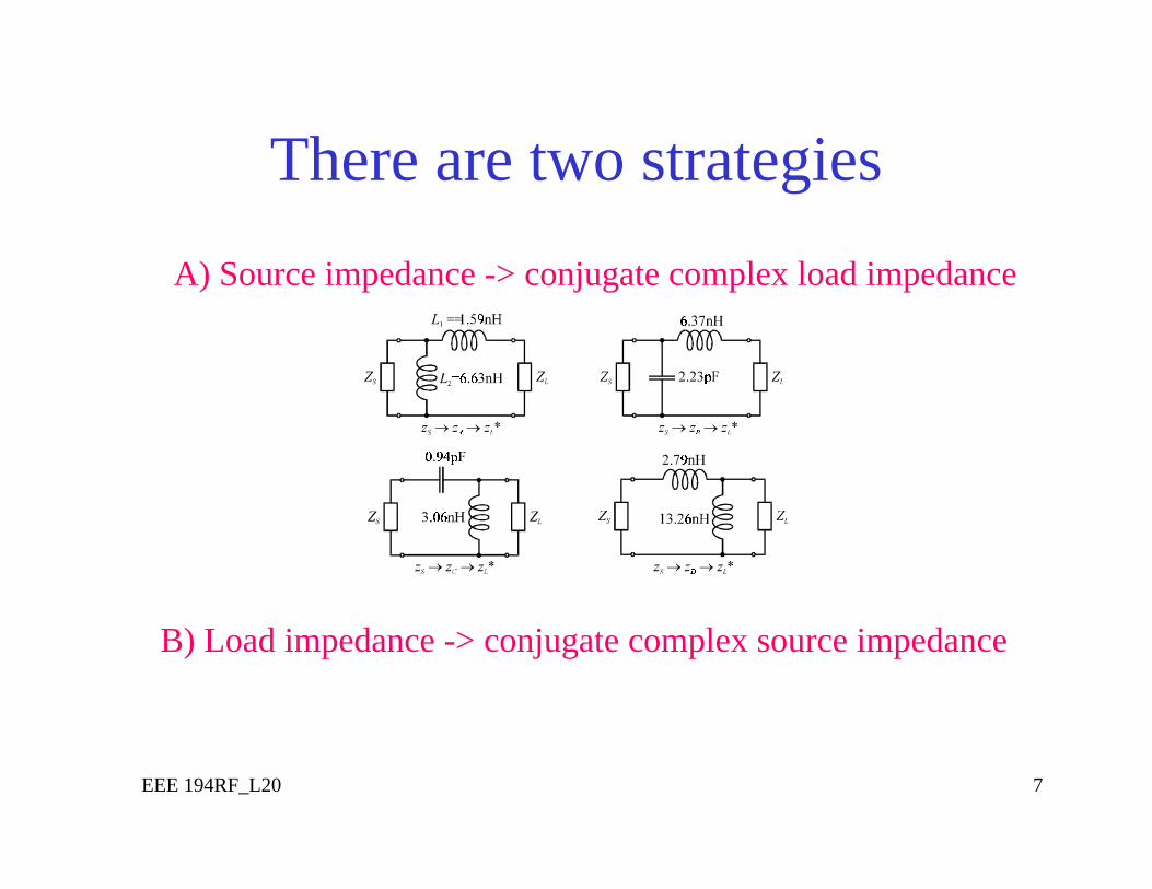
There are two strategies
A) Source impedance -> conjugate complex load impedance
B) Load impedance -> conjugate complex source impedance
EEE 194RF_L20 8
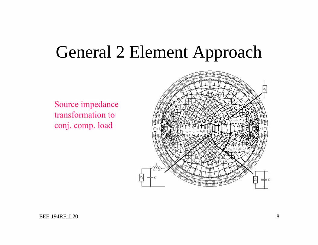
General 2 Element Approach
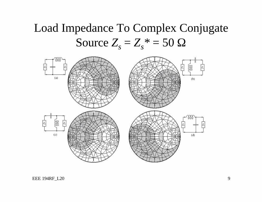
EEE 194RF_L20 9
Load Impedance To Complex Conjugate Source Zs = Zs* = 50 Ω
EEE 194RF_L20 10
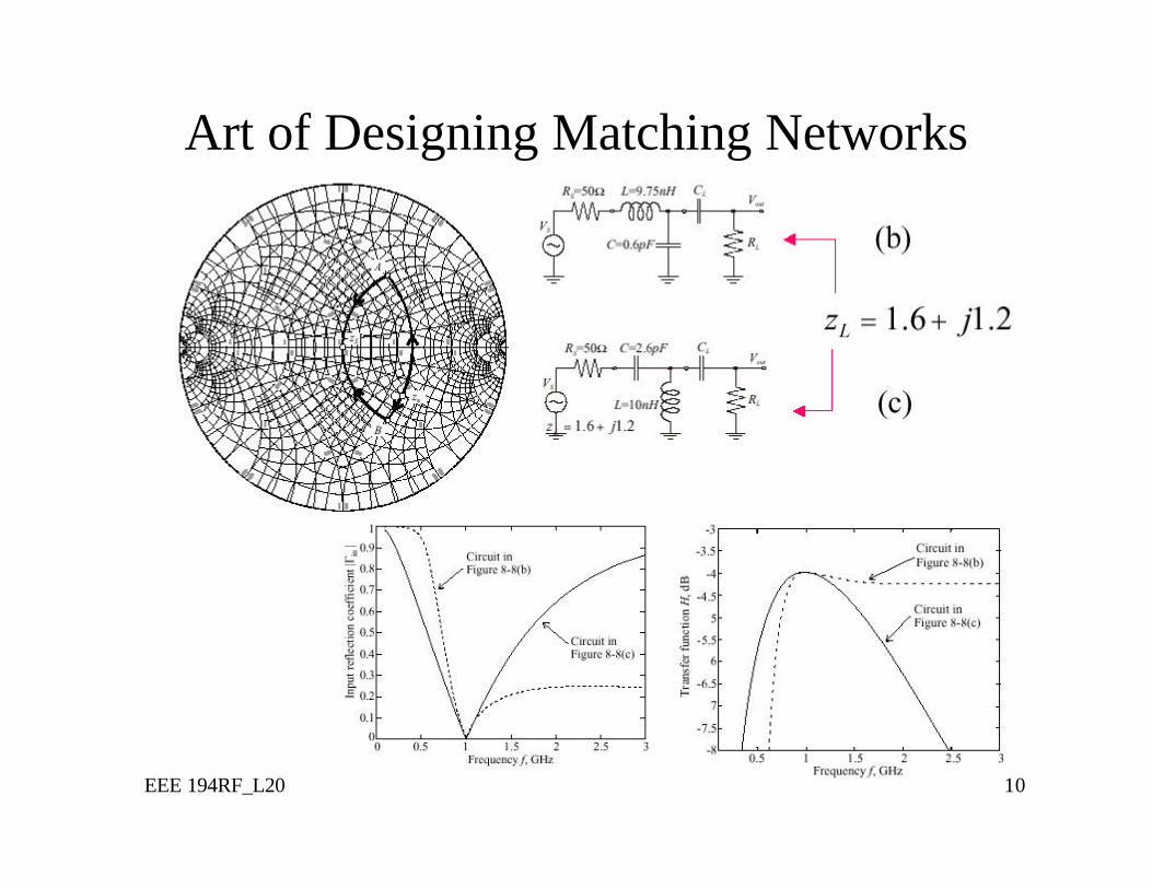
Art of Designing Matching Networks
EEE 194RF_L20 11
More Complicated Networks
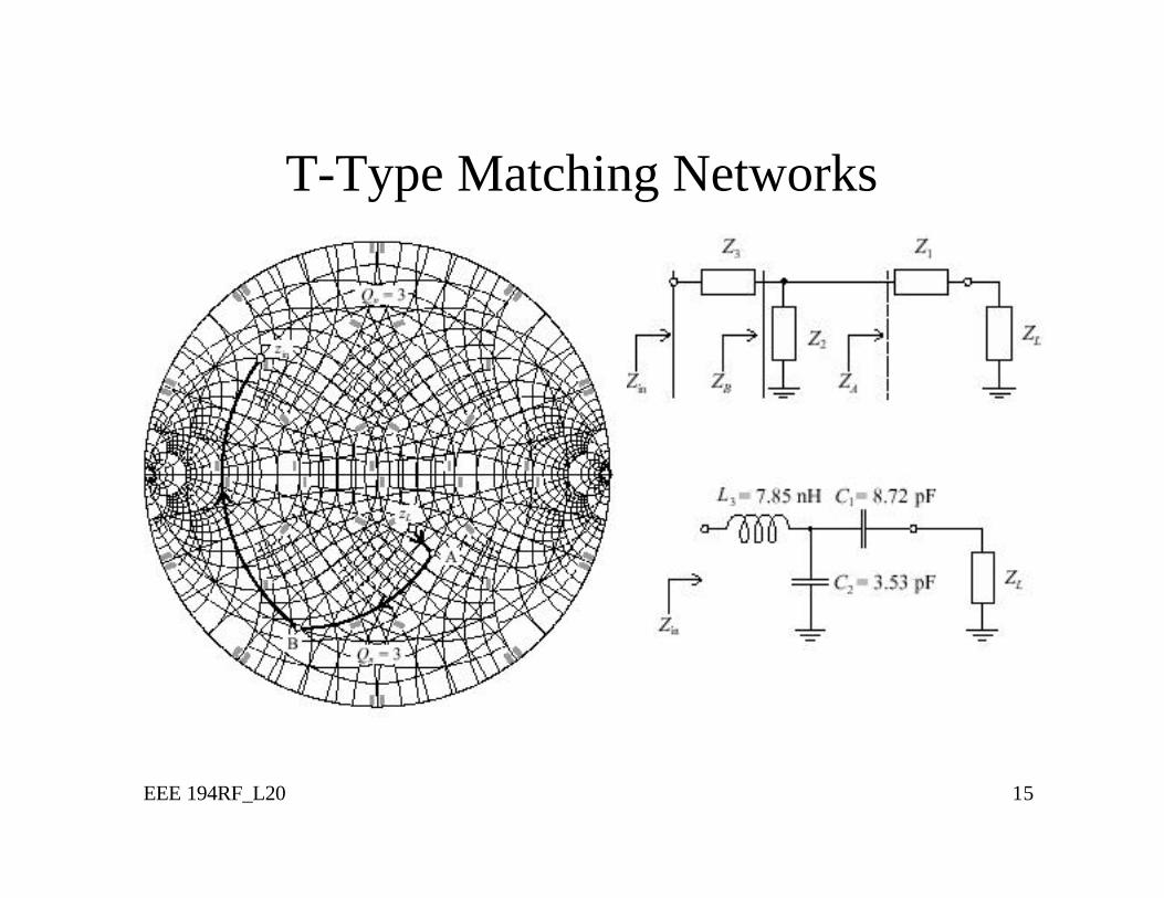
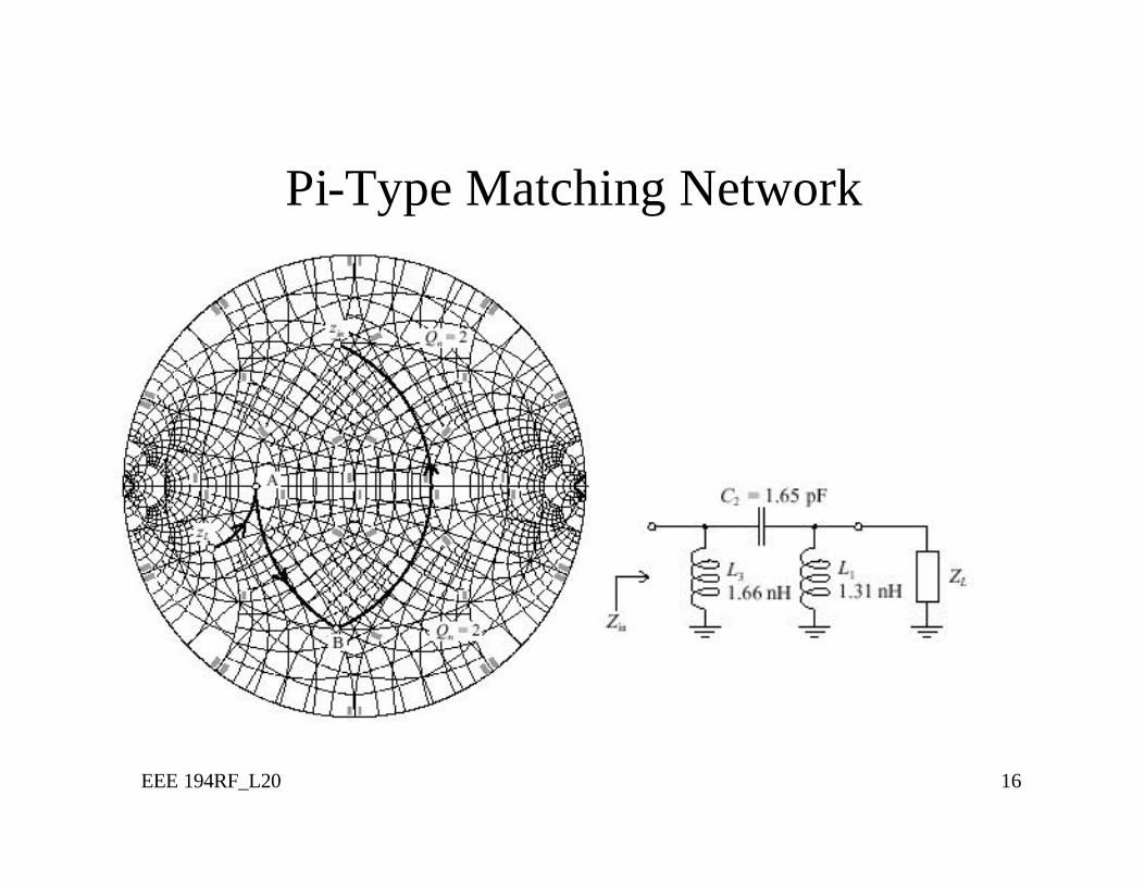
• Three-element Pi and T networks permit the matching of almost any load conditions
• Added element has the advantage of more flexibility in the design process (fine tuning)
• Provides quality factor design (see Ex. 8.4)
EEE 194RF_L20 12
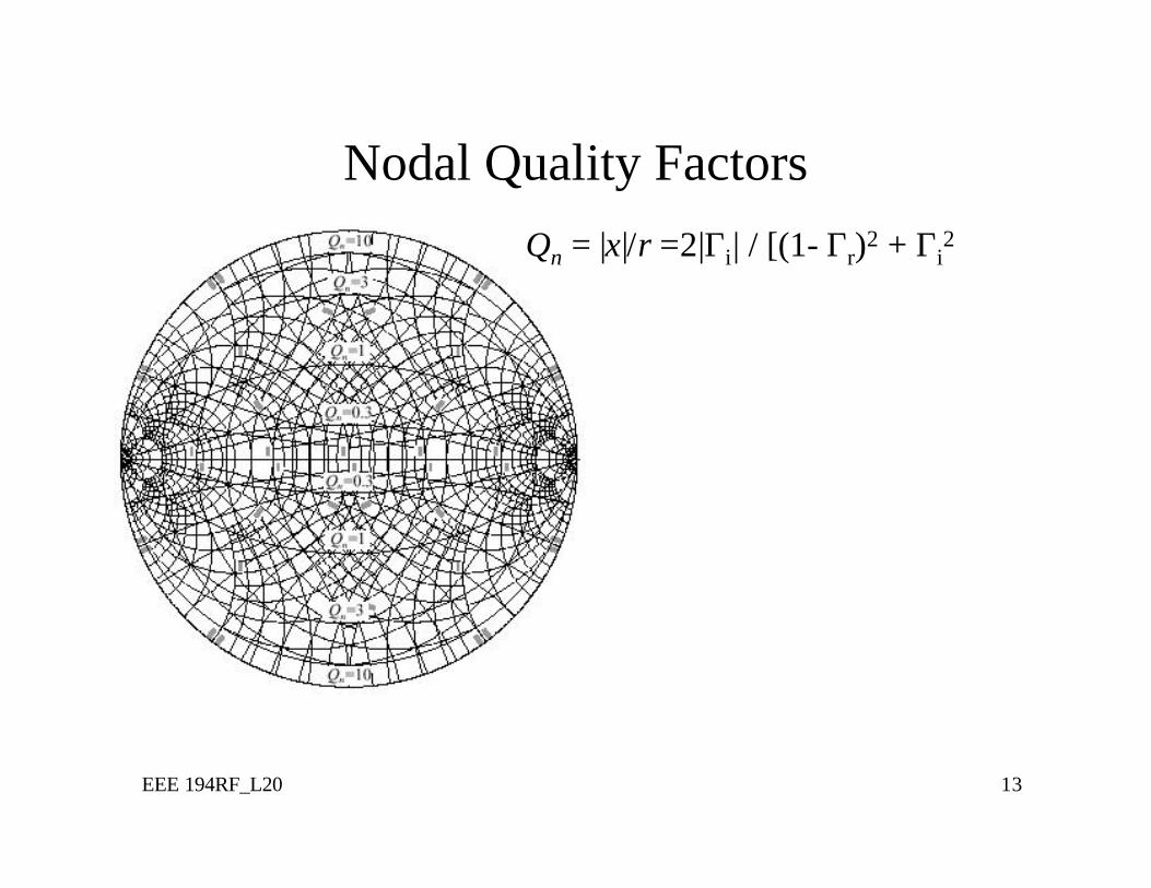
Quality Factor• Resonance effect has implications on design of
matching network.• Loaded Quality Factor: QL = fO/BW• If we know the Quality Factor Q, then we can find
BW• Estimate Q of matching network using Nodal
Quality Factor Qn
• At each circuit node can find Qn = |Xs|/Rs or Qn = |BP|/GP and
• QL = Qn/2 true for any L-type Matching Network
EEE 194RF_L20 13
Nodal Quality FactorsQn = |x|/r =2|Γi| / [(1- Γr)2 + Γi
2
EEE 194RF_L20 14
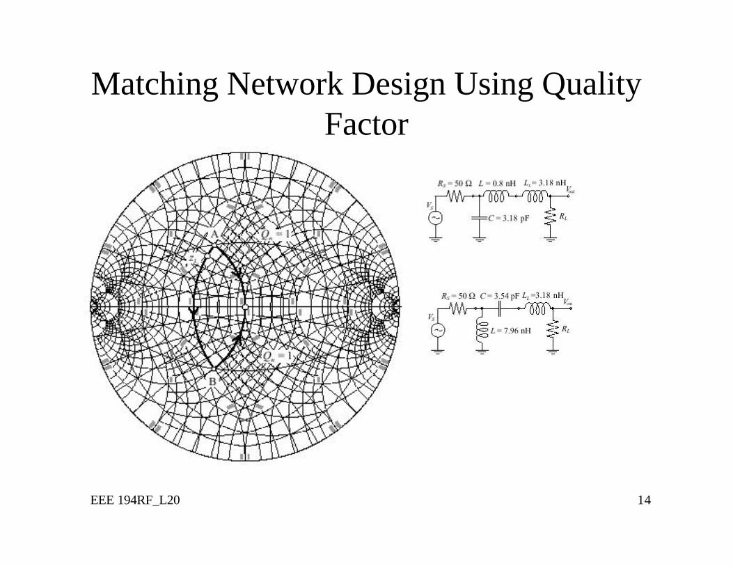
Matching Network Design Using Quality Factor
EEE 194RF_L20 15
T-Type Matching Networks
EEE 194RF_L20 16
Pi-Type Matching Network
EEE 194RF_L20 17
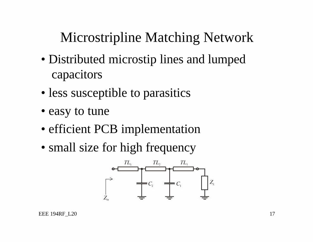
Microstripline Matching Network• Distributed microstip lines and lumped
capacitors• less susceptible to parasitics• easy to tune• efficient PCB implementation• small size for high frequency
EEE 194RF_L20 18
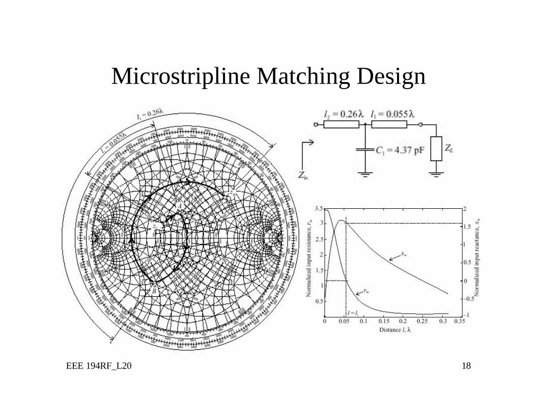
Microstripline Matching Design
EEE 194RF_L20 19
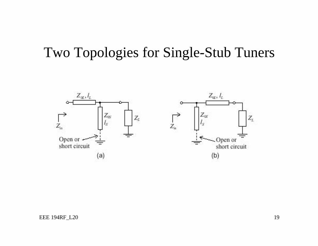
Two Topologies for Single-Stub Tuners
EEE 194RF_L20 20
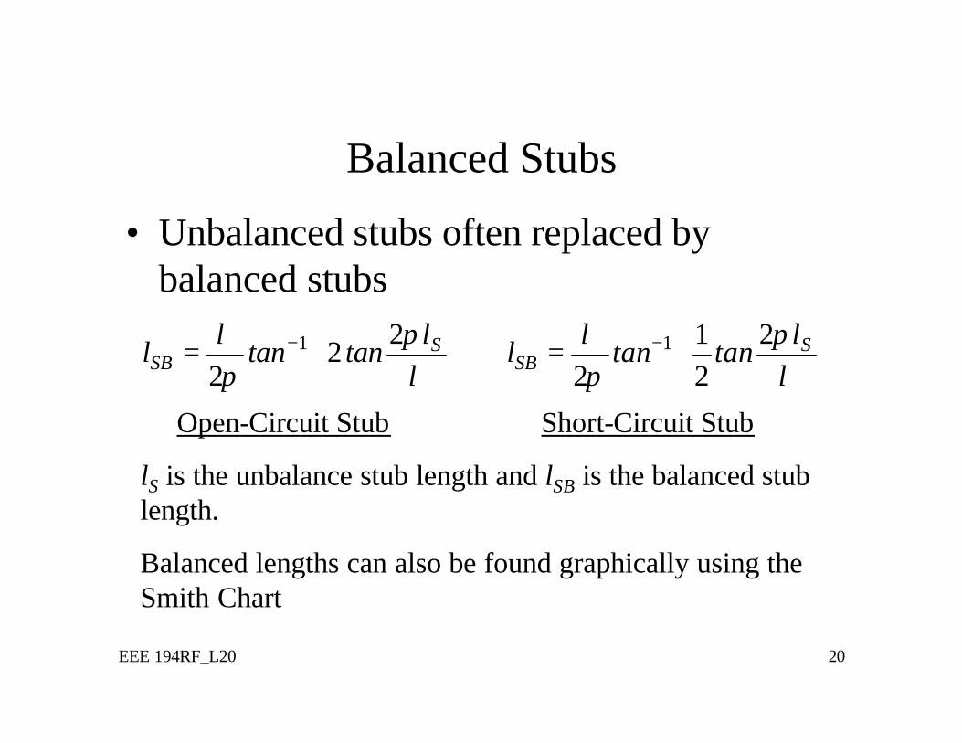
Balanced Stubs
• Unbalanced stubs often replaced by balanced stubs
1 22
2S
SBl
l tan tanπλ
π λ− =
1 21
2 2S
SBl
l tan tanπλ
π λ− =
Open-Circuit Stub Short-Circuit Stub
lS is the unbalance stub length and lSB is the balanced stub length.
Balanced lengths can also be found graphically using the Smith Chart
EEE 194RF_L20 21
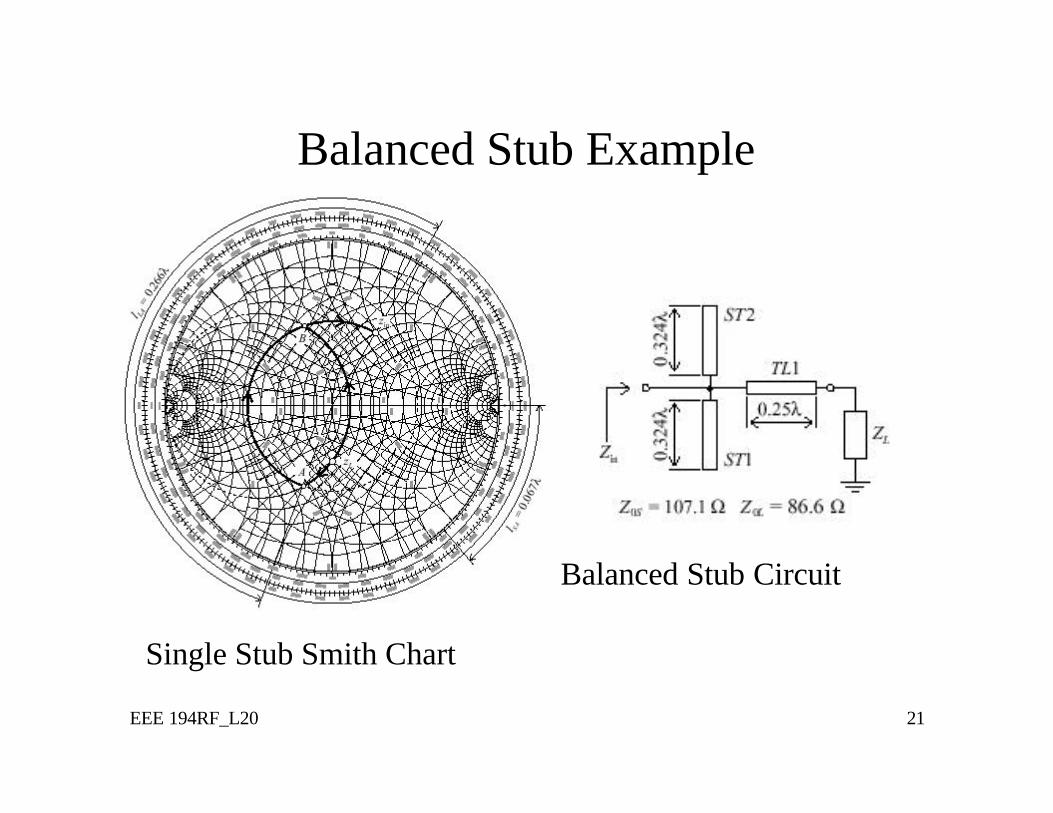
Balanced Stub Example
Single Stub Smith Chart
Balanced Stub Circuit
EEE 194RF_L20 22
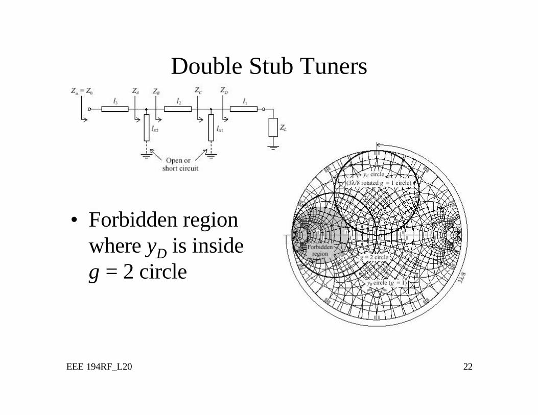
Double Stub Tuners
• Forbidden region where yD is inside g = 2 circle