Presentation on Plasma Physics at AWE - gov.uk · PDF filez 1975 AWE paper on a route to laser...
48
Transcript of Presentation on Plasma Physics at AWE - gov.uk · PDF filez 1975 AWE paper on a route to laser...
Contents
z Brief history of lasers at AWEz Helenz ORION
z The ORION laserz Configurationz Diagnostics
z ORION experimentsz Target fabrication
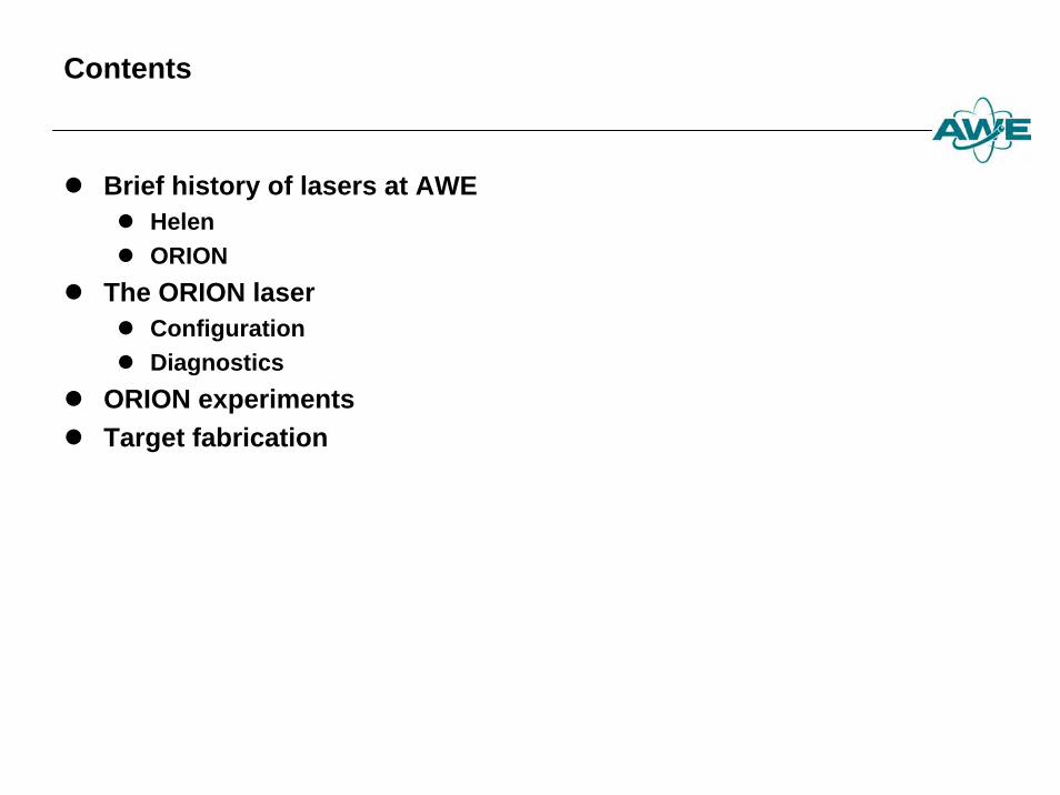
Laser work started at AWE in 1962.The AWE HELEN laser opened in 1979.
z 1960 Laser inventedz 1962 Fusion study at AWEz 1971 AWE paper on proposed programme for Laser Fusion
studiesz 1972 LLNL publishes work on Laser Fusionz 1975 AWE paper on a route to laser fusion (hohlraums)
z potential for study of materials properties in near-termz 1979 HELEN opened
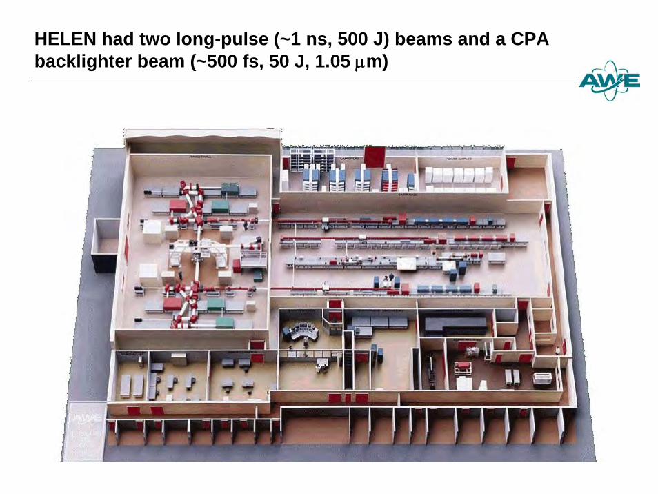
HELEN had two long-pulse (~1 ns, 500 J) beams and a CPA backlighter beam (~500 fs, 50 J, 1.05 μm)
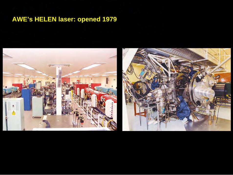
AWE’s HELEN laser: opened 1979
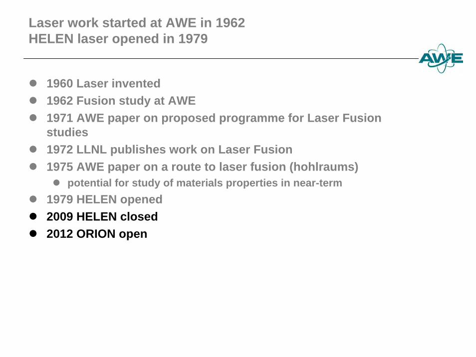
Laser work started at AWE in 1962HELEN laser opened in 1979
z 1960 Laser inventedz 1962 Fusion study at AWEz 1971 AWE paper on proposed programme for Laser Fusion
studiesz 1972 LLNL publishes work on Laser Fusionz 1975 AWE paper on a route to laser fusion (hohlraums)
z potential for study of materials properties in near-termz 1979 HELEN openedz 2009 HELEN closedz 2012 ORION open
Slide 7 of many
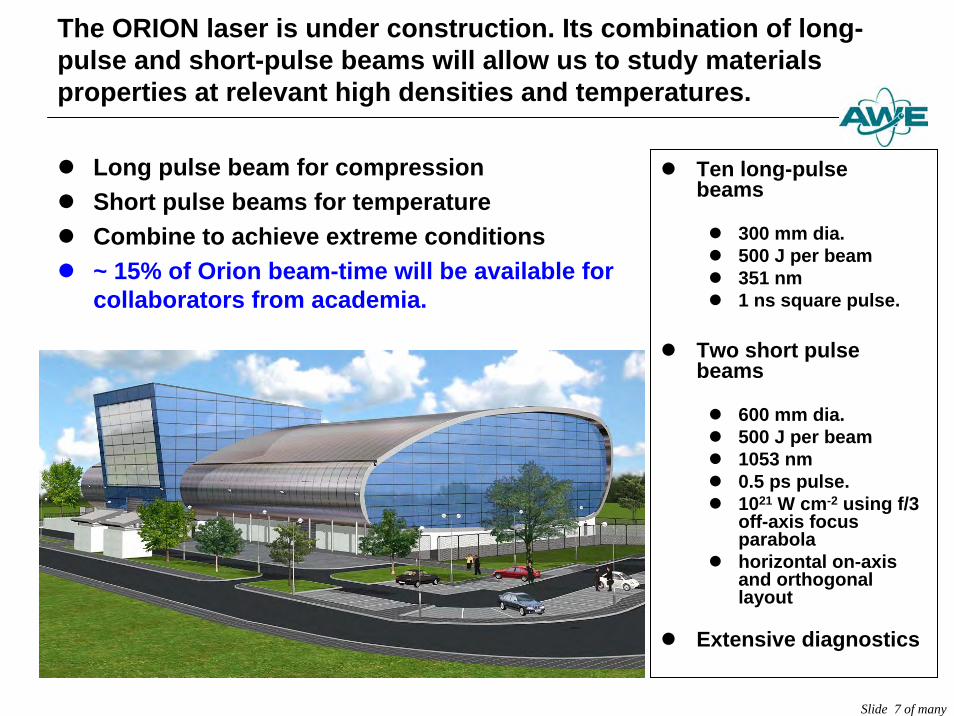
The ORION laser is under construction. Its combination of long-pulse and short-pulse beams will allow us to study materials properties at relevant high densities and temperatures.
z Long pulse beam for compressionz Short pulse beams for temperaturez Combine to achieve extreme conditionsz ~ 15% of Orion beam-time will be available for
collaborators from academia.
z Ten long-pulse beams
z 300 mm dia.z 500 J per beamz 351 nmz 1 ns square pulse.
z Two short pulse beams
z 600 mm dia.z 500 J per beamz 1053 nmz 0.5 ps pulse. z 1021 W cm-2 using f/3
off-axis focus parabola
z horizontal on-axis and orthogonal layout
z Extensive diagnostics
Slide 8 of many
ORION
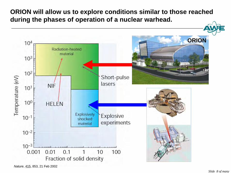
Nature, 415, 853, 21 Feb 2002
ORION will allow us to explore conditions similar to those reached during the phases of operation of a nuclear warhead.
Slide 9 of many
Slide 10 of many
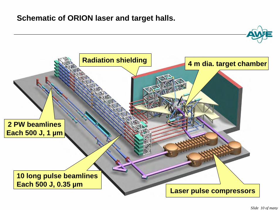
Schematic of ORION laser and target halls.
2 PW beamlinesEach 500 J, 1 µm
10 long pulse beamlinesEach 500 J, 0.35 µm
Radiation shielding 4 m dia. target chamber
Laser pulse compressors
Slide 11 of many
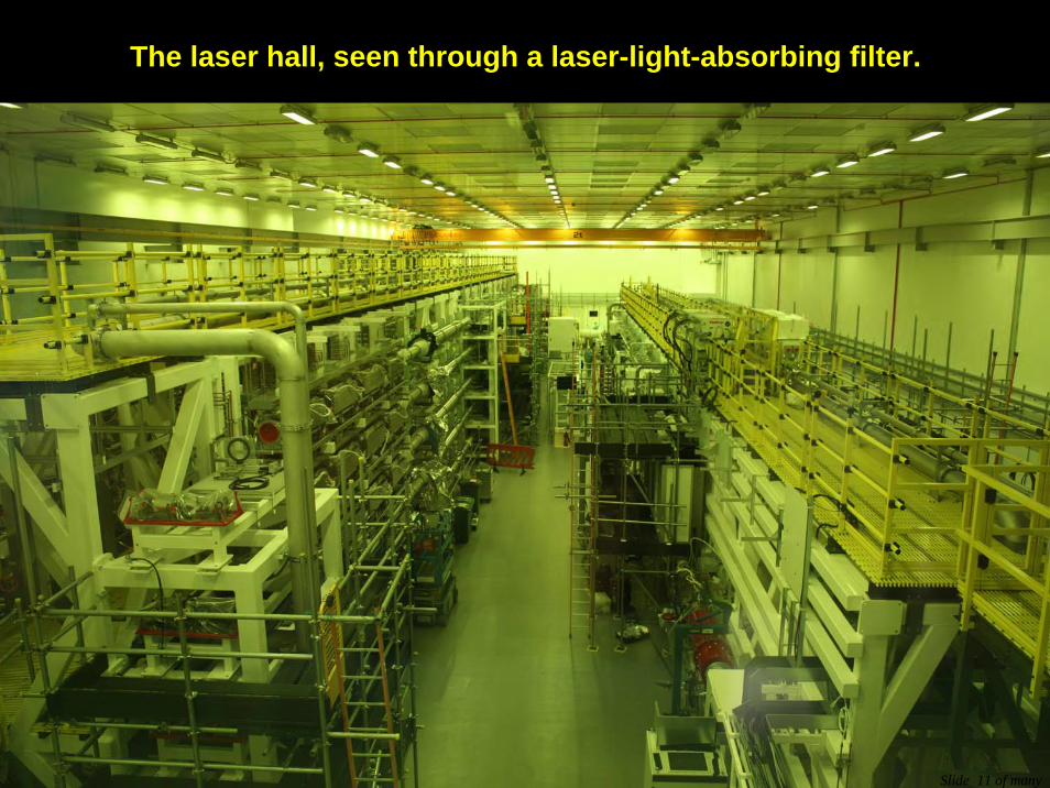
The laser hall, seen through a laser-light-absorbing filter.
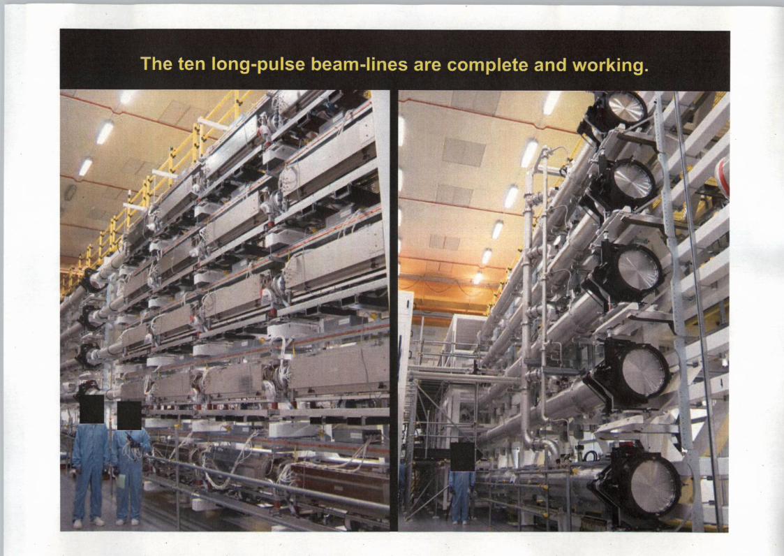
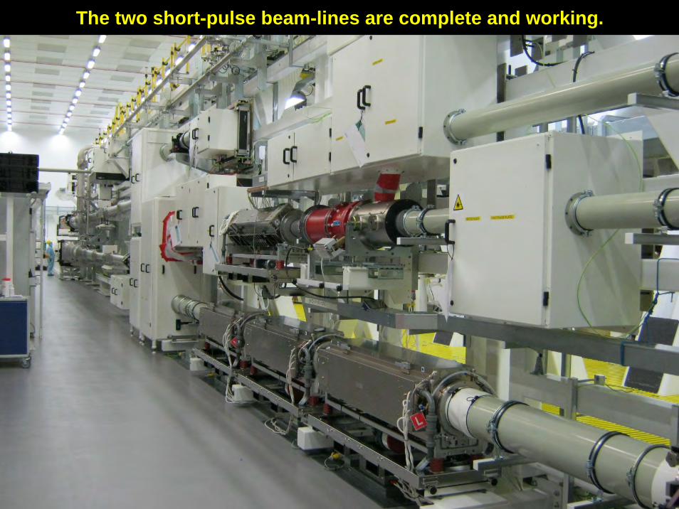
The two short-pulse beam-lines are complete and working.
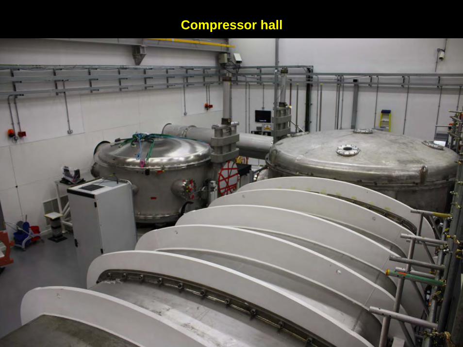
Compressor hall
Slide 14 of many
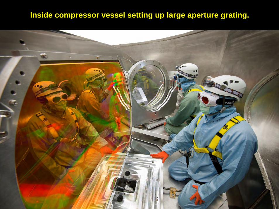
Inside compressor vessel setting up large aperture grating.
Slide 15 of many
Slide 17 of many
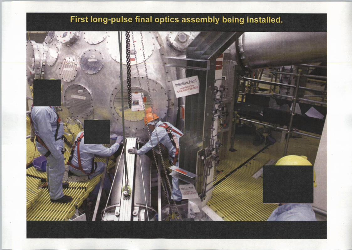
z
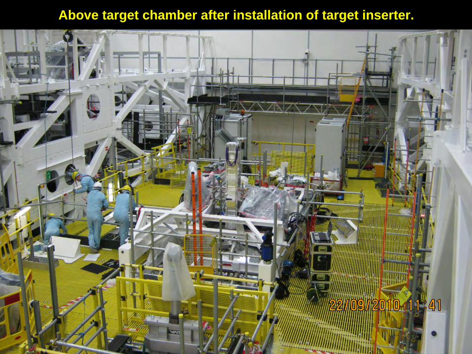
Above target chamber after installation of target inserter.
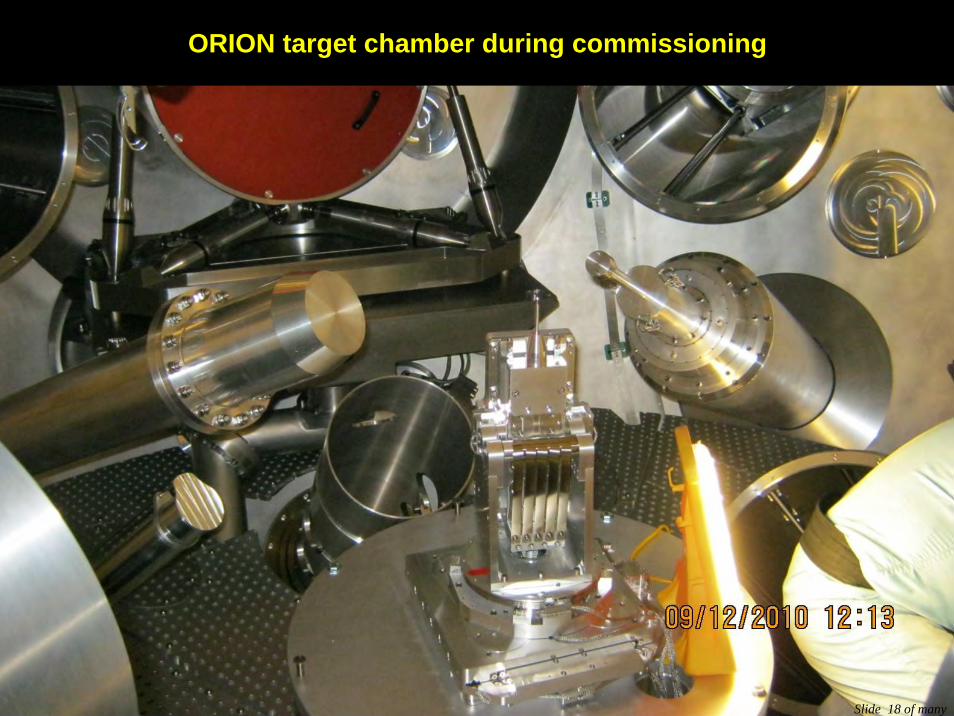
ORION target chamber during commissioning
Slide 18 of many
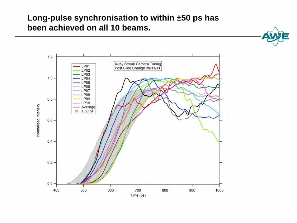
Long-pulse synchronisation to within ±50 ps has been achieved on all 10 beams.
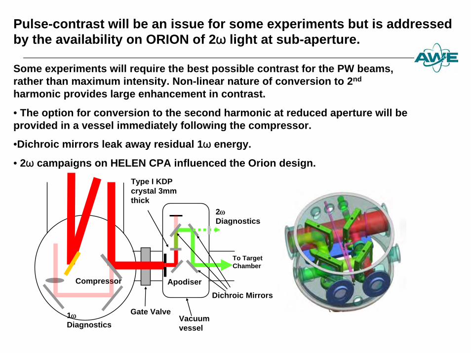
Pulse-contrast will be an issue for some experiments but is addressed by the availability on ORION of 2ω light at sub-aperture.
Some experiments will require the best possible contrast for the PW beams, rather than maximum intensity. Non-linear nature of conversion to 2nd
harmonic provides large enhancement in contrast.
• The option for conversion to the second harmonic at reduced aperture will be provided in a vessel immediately following the compressor.
•Dichroic mirrors leak away residual 1ω energy.
• 2ω campaigns on HELEN CPA influenced the Orion design.
Compressor
Gate Valve
Type I KDP crystal 3mm thick
2ωDiagnostics
To Target Chamber
Dichroic Mirrors
Vacuum vessel
Apodiser
1ωDiagnostics
Slide 21 of many
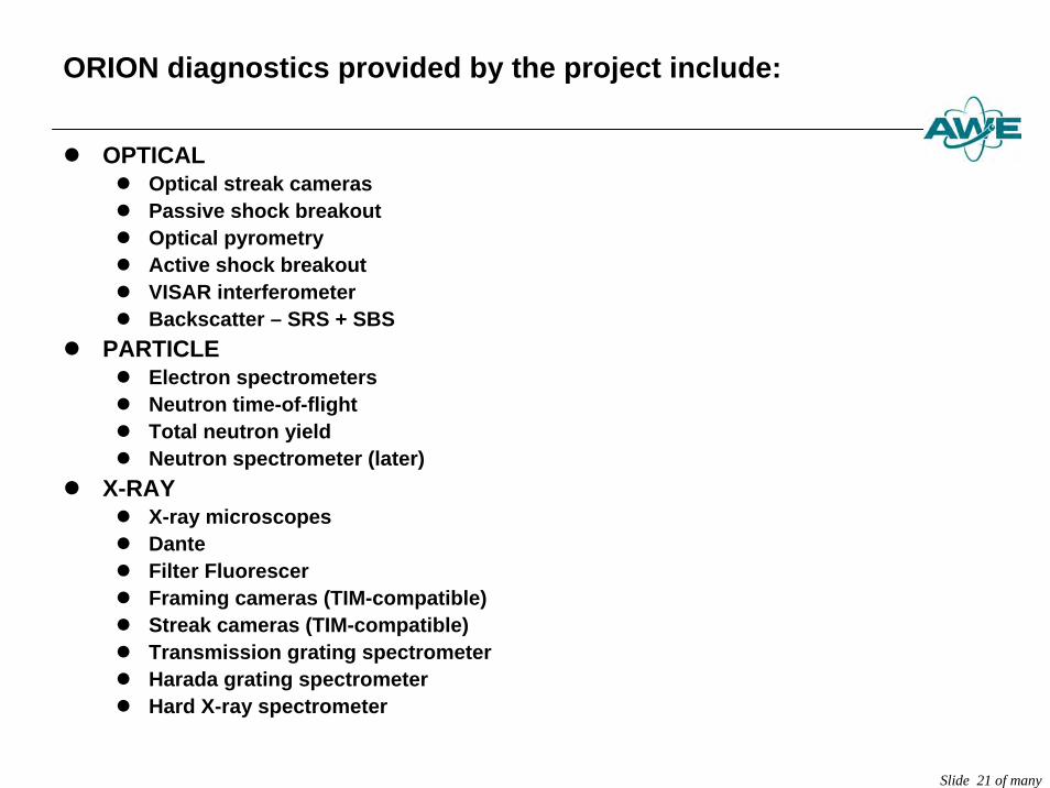
ORION diagnostics provided by the project include:
z OPTICALz Optical streak camerasz Passive shock breakout z Optical pyrometryz Active shock breakoutz VISAR interferometerz Backscatter – SRS + SBS
z PARTICLEz Electron spectrometersz Neutron time-of-flightz Total neutron yieldz Neutron spectrometer (later)
z X-RAYz X-ray microscopes z Dantez Filter Fluorescerz Framing cameras (TIM-compatible)z Streak cameras (TIM-compatible)z Transmission grating spectrometerz Harada grating spectrometerz Hard X-ray spectrometer
Slide 22 of many
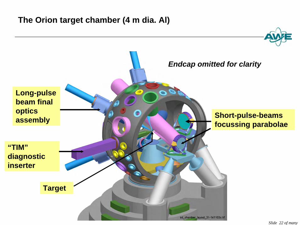
The Orion target chamber (4 m dia. Al)
Endcap omitted for clarity
“TIM”diagnostic inserter
Long-pulse beam final optics assembly Short-pulse-beams
focussing parabolae
Target
Slide 23 of many
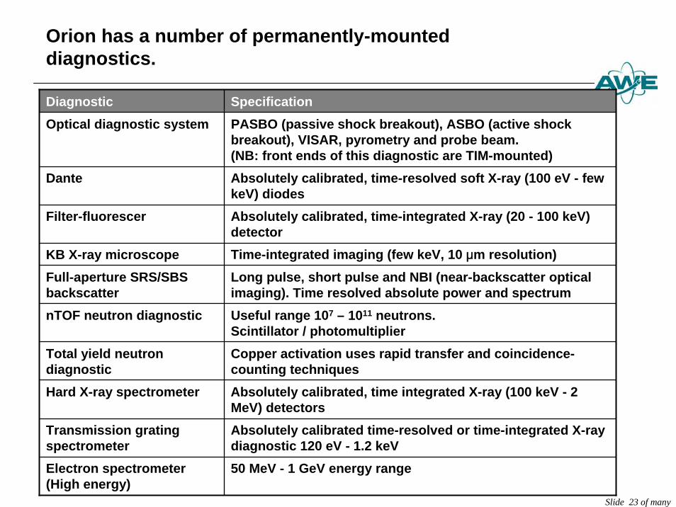
Orion has a number of permanently-mounted diagnostics.
Diagnostic SpecificationOptical diagnostic system PASBO (passive shock breakout), ASBO (active shock
breakout), VISAR, pyrometry and probe beam.(NB: front ends of this diagnostic are TIM-mounted)
Dante Absolutely calibrated, time-resolved soft X-ray (100 eV - few keV) diodes
Filter-fluorescer Absolutely calibrated, time-integrated X-ray (20 - 100 keV) detector
KB X-ray microscope Time-integrated imaging (few keV, 10 μm resolution)Full-aperture SRS/SBS backscatter
Long pulse, short pulse and NBI (near-backscatter optical imaging). Time resolved absolute power and spectrum
nTOF neutron diagnostic Useful range 107 – 1011 neutrons.Scintillator / photomultiplier
Total yield neutron diagnostic
Copper activation uses rapid transfer and coincidence-counting techniques
Hard X-ray spectrometer Absolutely calibrated, time integrated X-ray (100 keV - 2 MeV) detectors
Transmission grating spectrometer
Absolutely calibrated time-resolved or time-integrated X-raydiagnostic 120 eV - 1.2 keV
Electron spectrometer (High energy)
50 MeV - 1 GeV energy range
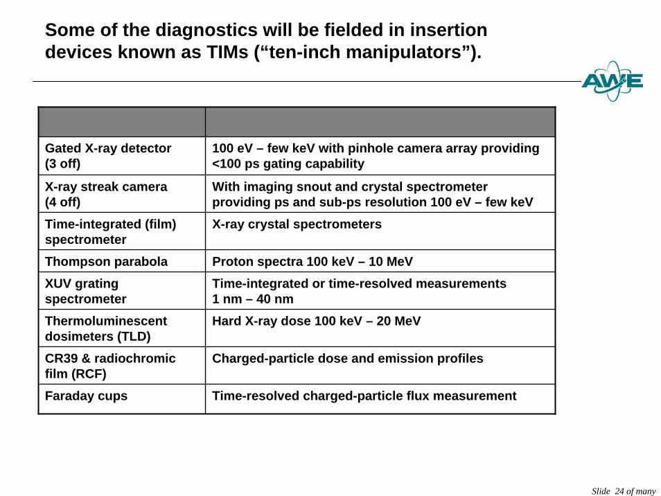
Slide 24 of many
Diagnostic Specification
Gated X-ray detector (3 off)
100 eV – few keV with pinhole camera array providing <100 ps gating capability
X-ray streak camera(4 off)
With imaging snout and crystal spectrometer providing ps and sub-ps resolution 100 eV – few keV
Time-integrated (film) spectrometer
X-ray crystal spectrometers
Thompson parabola Proton spectra 100 keV – 10 MeVXUV grating spectrometer
Time-integrated or time-resolved measurements1 nm – 40 nm
Thermoluminescentdosimeters (TLD)
Hard X-ray dose 100 keV – 20 MeV
CR39 & radiochromicfilm (RCF)
Charged-particle dose and emission profiles
Faraday cups Time-resolved charged-particle flux measurement
Some of the diagnostics will be fielded in insertion devices known as TIMs (“ten-inch manipulators”).
Slide 25 of many
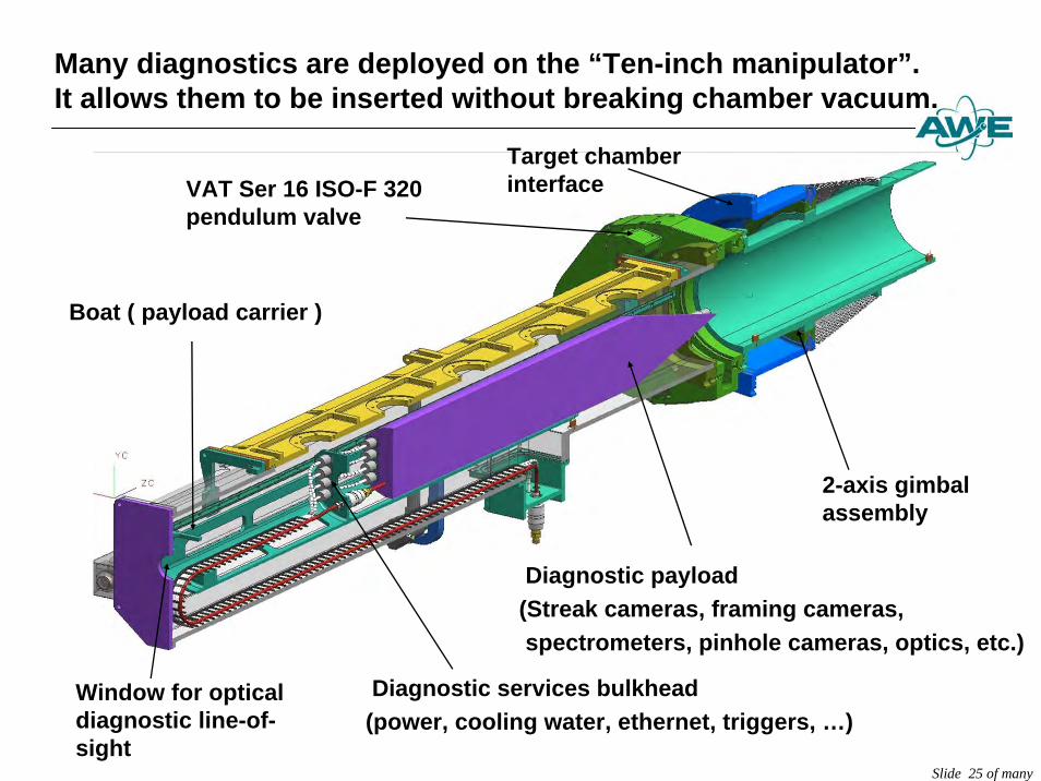
Many diagnostics are deployed on the “Ten-inch manipulator”.It allows them to be inserted without breaking chamber vacuum.
VAT Ser 16 ISO-F 320 pendulum valve
Window for optical diagnostic line-of-sight
2-axis gimbalassembly
Boat ( payload carrier )
Target chamber interface
Diagnostic services bulkhead(power, cooling water, ethernet, triggers, …)
Diagnostic payload(Streak cameras, framing cameras,spectrometers, pinhole cameras, optics, etc.)
Slide 26 of many
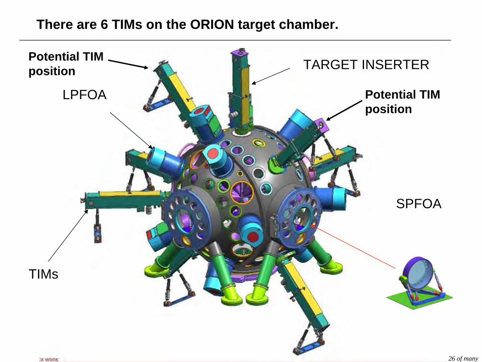
TARGET INSERTER
TIMs
LPFOA
SPFOA
Potential TIM position
There are 6 TIMs on the ORION target chamber.
Potential TIM position
27
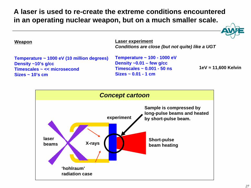
A laser is used to re-create the extreme conditions encountered in an operating nuclear weapon, but on a much smaller scale.
Laser experimentConditions are close (but not quite) like a UGT
Temperature ~ 100 - 1000 eVDensity ~0.01 – few g/ccTimescales ~ 0.001 - 50 nsSizes ~ 0.01 - 1 cm
1eV ≈ 11,600 Kelvin
Weapon
Temperature ~ 1000 eV (10 million degrees)Density ~10’s g/ccTimescales ~ << microsecondSizes ~ 10’s cm
laserbeams X-rays
experiment
‘hohlraum’radiation case
Short-pulse beam heating
Sample is compressed bylong-pulse beams and heated by short-pulse beam.
Concept cartoon
Likely ORION experiments
z Opacityz Warm dense matterz Strength
Slide 28 of many
Slide 29 of many
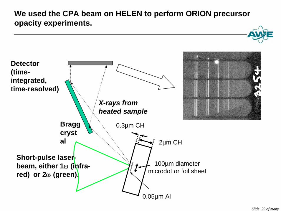
We used the CPA beam on HELEN to perform ORION precursor opacity experiments.
2µm CH
Short-pulse laser-beam, either 1ω (infra-red) or 2ω (green).
0.3µm CH
0.05µm Al
100µm diametermicrodot or foil sheet
Bragg crystal
Detector(time-integrated, time-resolved)
X-rays from heated sample
Slide 30 of many
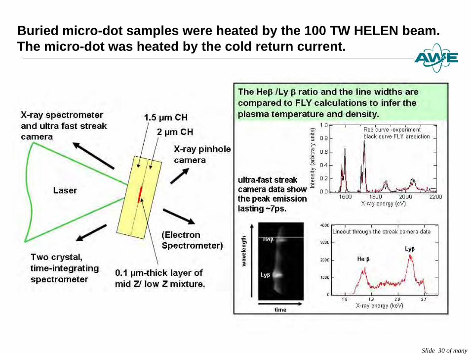
Buried micro-dot samples were heated by the 100 TW HELEN beam. The micro-dot was heated by the cold return current.
Slide 31 of many
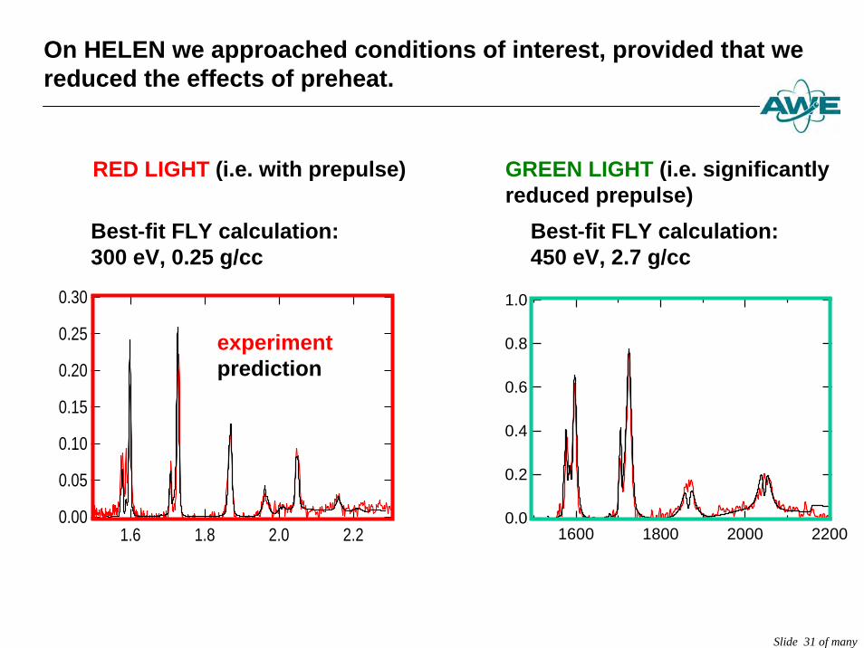
On HELEN we approached conditions of interest, provided that we reduced the effects of preheat.
Best-fit FLY calculation: 300 eV, 0.25 g/cc
Best-fit FLY calculation: 450 eV, 2.7 g/cc
RED LIGHT (i.e. with prepulse) GREEN LIGHT (i.e. significantly reduced prepulse)
0.30
0.25
0.20
0.15
0.10
0.05
0.002.22.01.81.6
experimentprediction
1.0
0.8
0.6
0.4
0.2
0.02200200018001600
Slide 32 of many
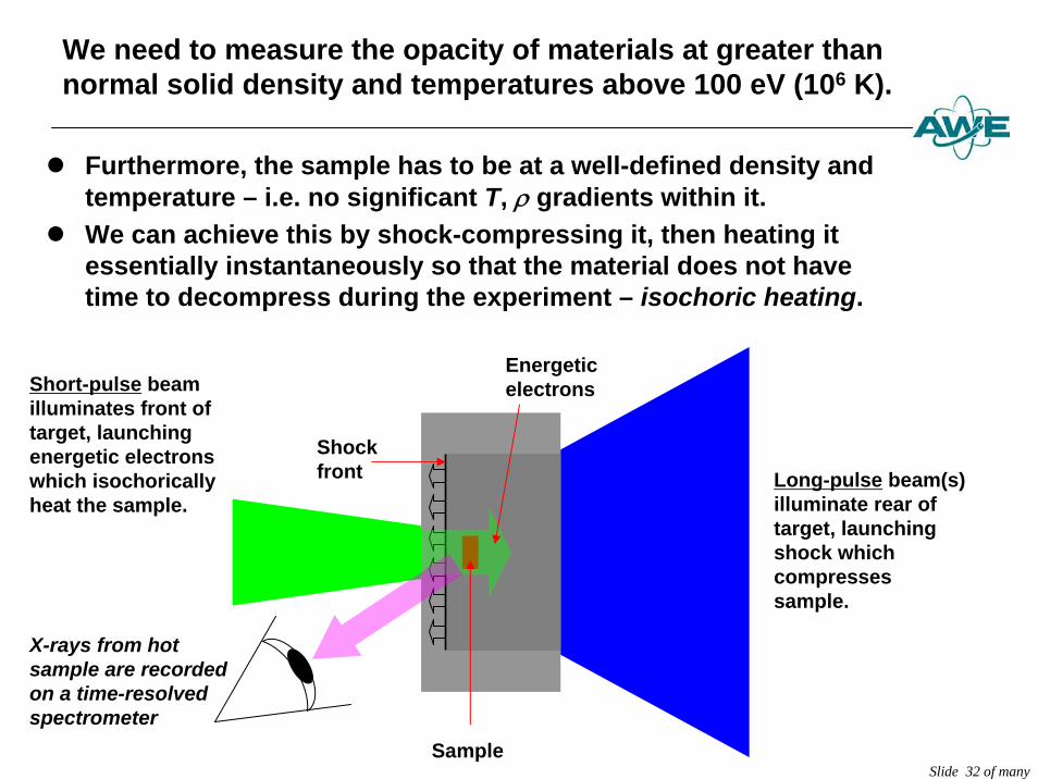
We need to measure the opacity of materials at greater than normal solid density and temperatures above 100 eV (106 K).
z Furthermore, the sample has to be at a well-defined density and temperature – i.e. no significant T, ρ gradients within it.
z We can achieve this by shock-compressing it, then heating it essentially instantaneously so that the material does not have time to decompress during the experiment – isochoric heating.
Long-pulse beam(s) illuminate rear oftarget, launching shock which compresses sample.
Short-pulse beam illuminates front of target, launching energetic electrons which isochoricallyheat the sample.
Energetic electrons
Sample
Shock front
X-rays from hot sample are recordedon a time-resolved spectrometer
Slide 33 of many
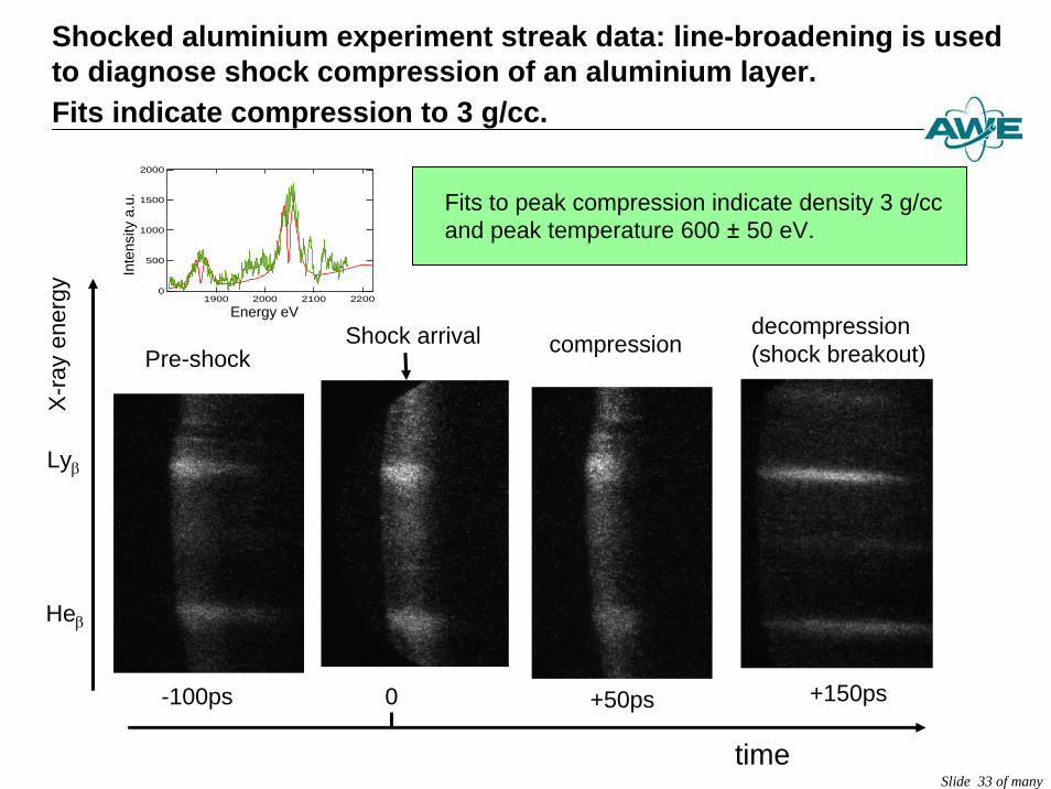
Shocked aluminium experiment streak data: line-broadening is used to diagnose shock compression of an aluminium layer.Fits indicate compression to 3 g/cc.
X-ra
y en
ergy
time
-100ps
compression
+50ps +150ps
Lyβ
Heβ
Shock arrival
0
decompression(shock breakout)Pre-shock
2000
1500
1000
500
02200210020001900
Energy eV
Inte
nsity
a.u
. Fits to peak compression indicate density 3 g/ccand peak temperature 600 ± 50 eV.
Slide 34 of many
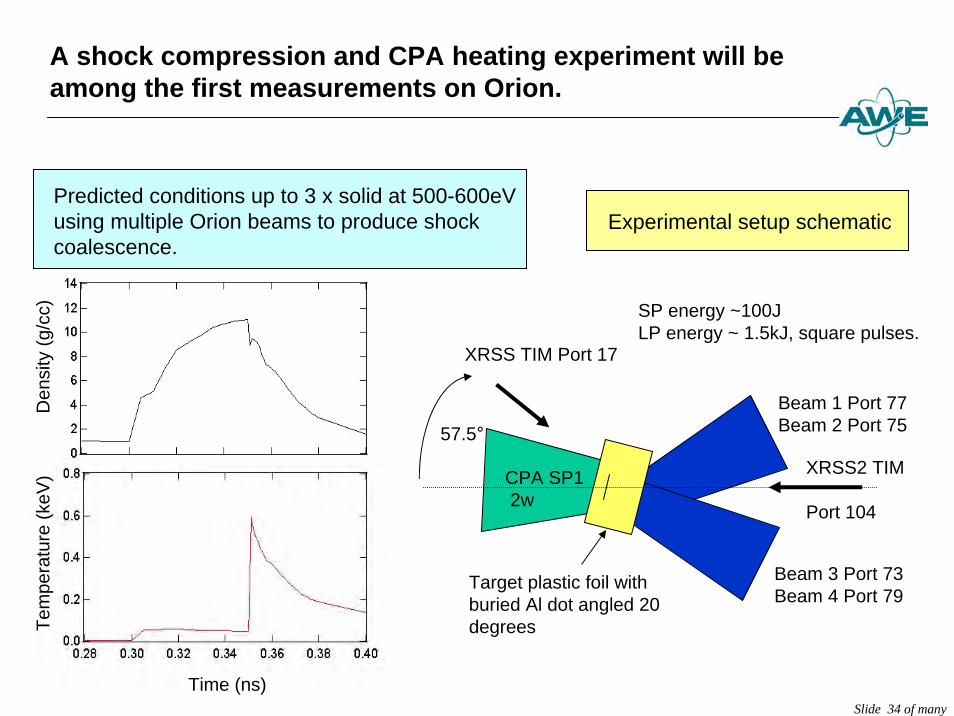
A shock compression and CPA heating experiment will be among the first measurements on Orion.
Den
sity
(g/c
c)Te
mpe
ratu
re (k
eV)
Time (ns)
XRSS2 TIM
Port 104
CPA SP12w
Target plastic foil with buried Al dot angled 20 degrees
XRSS TIM Port 17
57.5°Beam 1 Port 77Beam 2 Port 75
Beam 3 Port 73Beam 4 Port 79
SP energy ~100J LP energy ~ 1.5kJ, square pulses.
Predicted conditions up to 3 x solid at 500-600eV using multiple Orion beams to produce shock coalescence.
Experimental setup schematic
Slide 35 of many
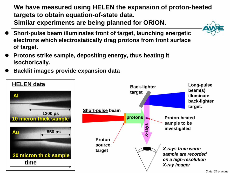
We have measured using HELEN the expansion of proton-heated targets to obtain equation-of-state data.Similar experiments are being planned for ORION.
z Short-pulse beam illuminates front of target, launching energetic electrons which electrostatically drag protons from front surface of target.
z Protons strike sample, depositing energy, thus heating it isochorically.
z Backlit images provide expansion data
Long-pulsebeam(s) illuminate back-lighter target.
Proton-heated sample to be investigated
Proton source target
Short-pulse beam
Back-lighter target
X-rays from warm sample are recordedon a high-resolution X-ray imager
protons
X-ra
ys
1200 ps
Al
10 micron thick sample
Au 850 ps
20 micron thick sample
HELEN data
time
Slide 36 of many
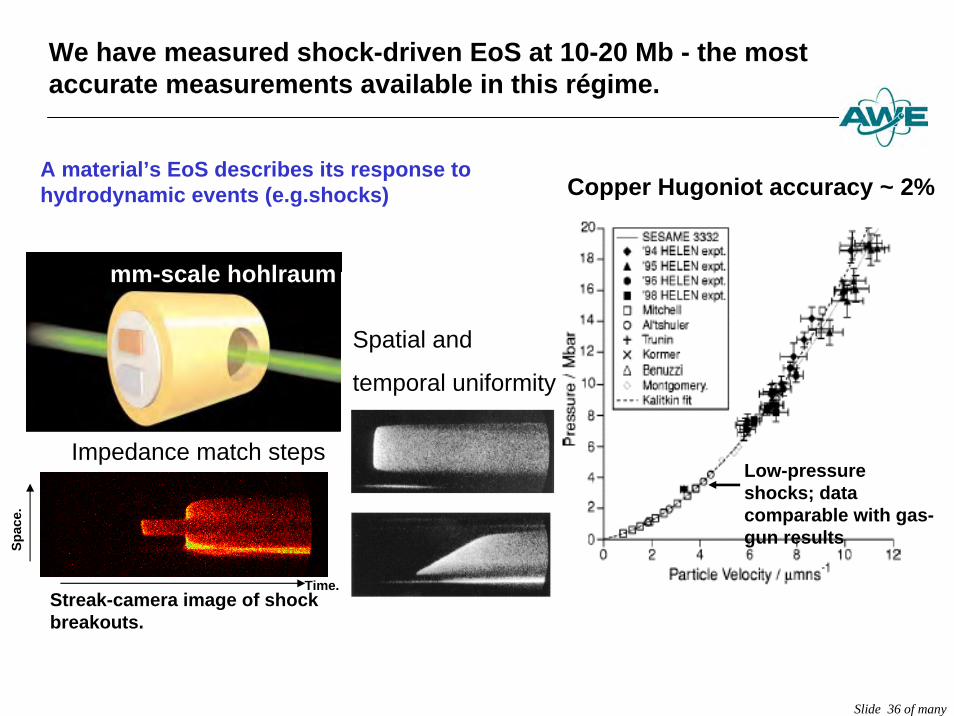
We have measured shock-driven EoS at 10-20 Mb - the most accurate measurements available in this régime.
Impedance match steps
Copper Hugoniot accuracy ~ 2%
Streak-camera image of shock breakouts.
Time.
Spac
e.
Low-pressure shocks; data comparable with gas-gun results
Spatial and
temporal uniformity
mm-scale hohlraum
A material’s EoS describes its response tohydrodynamic events (e.g.shocks)
Slide 37 of many
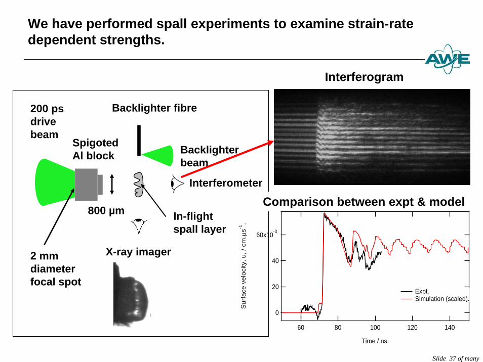
We have performed spall experiments to examine strain-rate dependent strengths.
Backlighter fibre
X-ray imager
Interferometer
SpigotedAl block
200 psdrive beam
Backlighterbeam
800 µm
2 mm diameter focal spot
In-flight spall layer
Interferogram
60x10-3
40
20
0
Surf
ace
velo
city
, u, / cm
.μs-1
.
1401201008060
Time / ns.
Expt. Simulation (scaled).
Comparison between expt & model
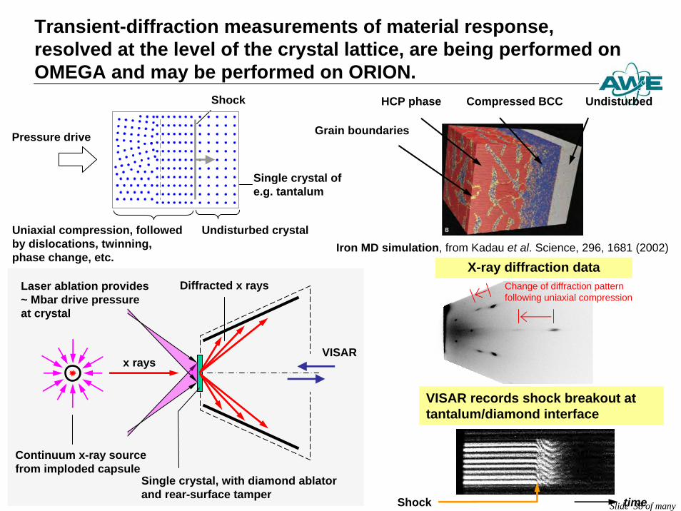
Transient-diffraction measurements of material response, resolved at the level of the crystal lattice, are being performed on OMEGA and may be performed on ORION.
Slide 38 of many
X-ray diffraction dataIron MD simulation, from Kadau et al. Science, 296, 1681 (2002)
UndisturbedCompressed BCCHCP phase
Grain boundaries
VISAR records shock breakout at tantalum/diamond interface
timeShock
Change of diffraction patternfollowing uniaxial compression
Continuum x-ray sourcefrom imploded capsule
Diffracted x rays
Single crystal, with diamond ablator and rear-surface tamper
VISARx rays
Laser ablation provides ~ Mbar drive pressure at crystal
Pressure drive
Undisturbed crystalUniaxial compression, followedby dislocations, twinning,phase change, etc.
Shock
Single crystal of e.g. tantalum
Slide 39 of many
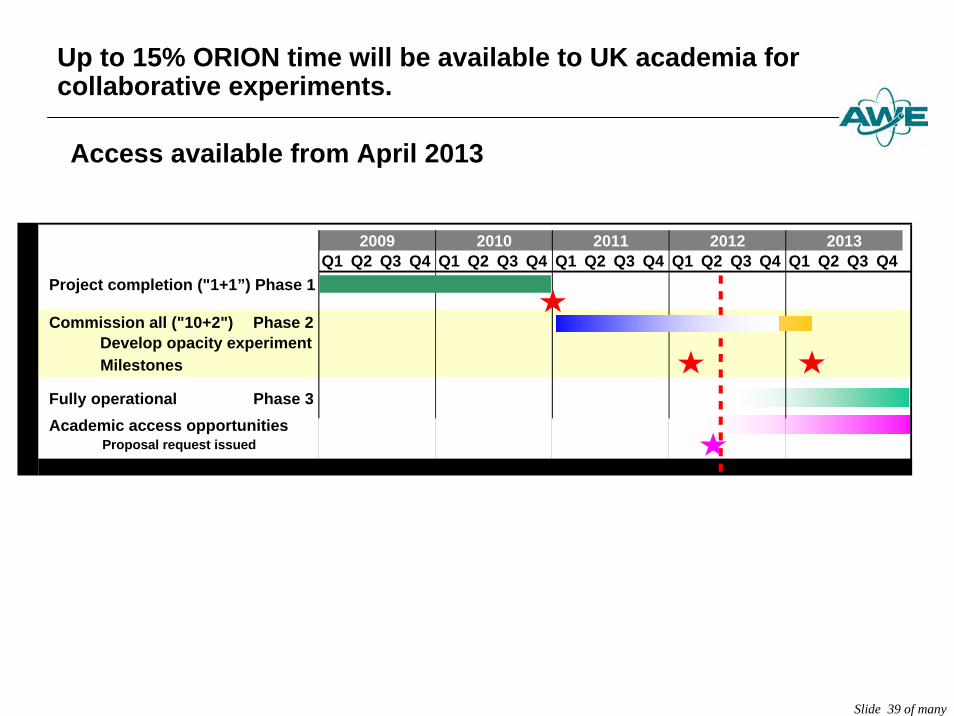
Up to 15% ORION time will be available to UK academia for collaborative experiments.
Access available from April 2013
Q1 Q2 Q3 Q4 Q1 Q2 Q3 Q4 Q1 Q2 Q3 Q4 Q1 Q2 Q3 Q4 Q1 Q2 Q3 Q4
Develop opacity experiment
Fully operational Phase 3
20132009 2010 2011 2012
Project completion ("1+1”) Phase 1
Commission all ("10+2") Phase 2
Milestones
Academic access opportunitiesProposal request issued
Slide 40 of many
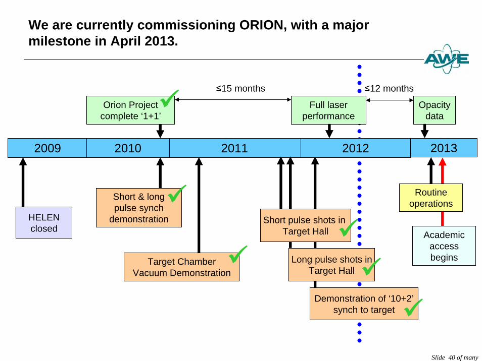
We are currently commissioning ORION, with a major milestone in April 2013.
≤12 months
2011
Target Chamber Vacuum Demonstration
Short & long pulse synch
demonstration
Orion Project complete ‘1+1’
Full laser performance
≤15 months
Opacitydata
2009 2010 2012
HELENclosed
Demonstration of ‘10+2’synch to target
2013
Short pulse shots inTarget Hall
Long pulse shots inTarget Hall
Academic access begins
Routine operations9
9
9
9
9
9
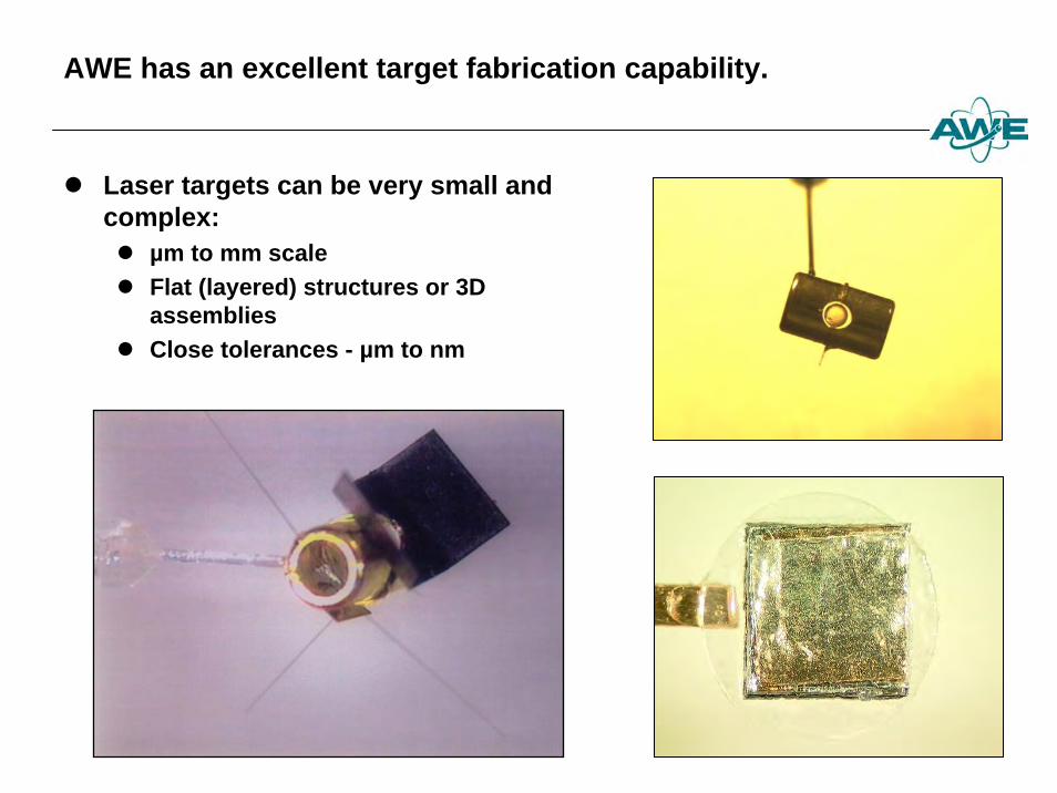
AWE has an excellent target fabrication capability.
z Laser targets can be very small and complex: z µm to mm scalez Flat (layered) structures or 3D
assembliesz Close tolerances - µm to nm
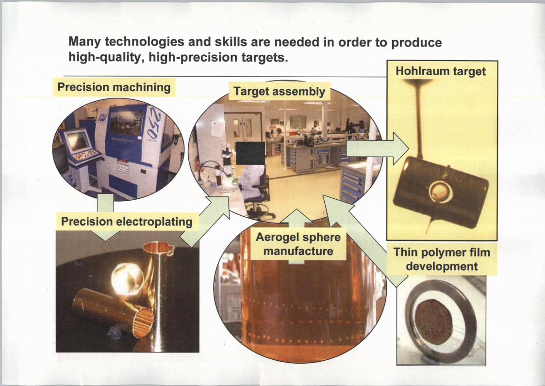
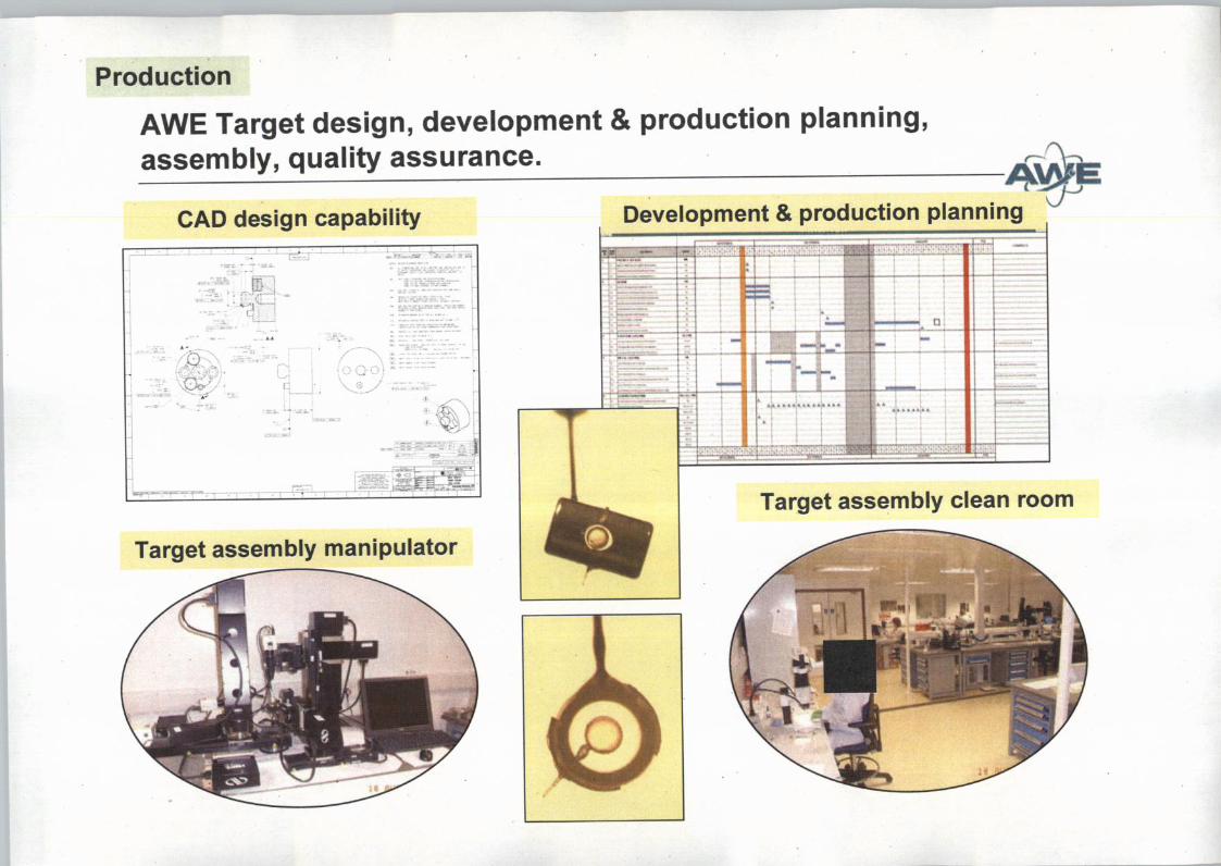
Target fabrication involves four key themes:
z Materials Science - make the raw materialsz Engineering - form it to the shape we needz Characterisation & metrology - do the components meet
requirements?z Production - assemble the targets
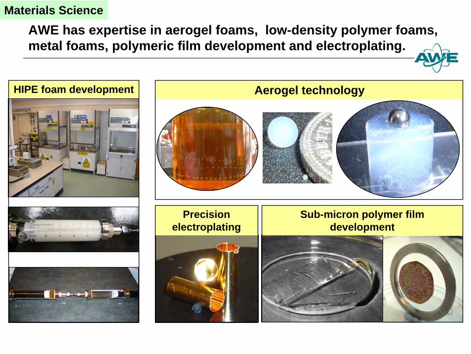
AWE has expertise in aerogel foams, low-density polymer foams, metal foams, polymeric film development and electroplating.
Materials Science
HIPE foam development
Precision electroplating
Sub-micron polymer film development
Aerogel technology
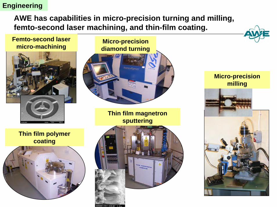
Engineering
Micro-precision diamond turning
Micro-precision milling
Femto-second lasermicro-machining
Thin film magnetron sputtering
Thin film polymer coating
AWE has capabilities in micro-precision turning and milling, femto-second laser machining, and thin-film coating.
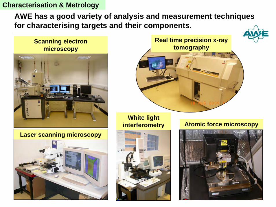
Characterisation & Metrology
Real time precision x-ray tomography
Laser scanning microscopy
White light interferometry Atomic force microscopy
Scanning electron microscopy
AWE has a good variety of analysis and measurement techniques for characterising targets and their components.
Summary
z ORION commissioning underway; commissioning milestone is March 2013z All 10 long-pulse beams are available (~400 J in 1 ns)z Both short-pulse beams are available (~300 J in 0.5 ps)z All have been synchronised to within ± 50 ps.
z During 2012 we are working towards an MoD-mandated experiment milestone (deadline: March 2013) to show that the laser can generate appropriate data
z Academic access starts 2013, with 15% of ORION time available.