Precision Design- Stiffness Enhancement
20
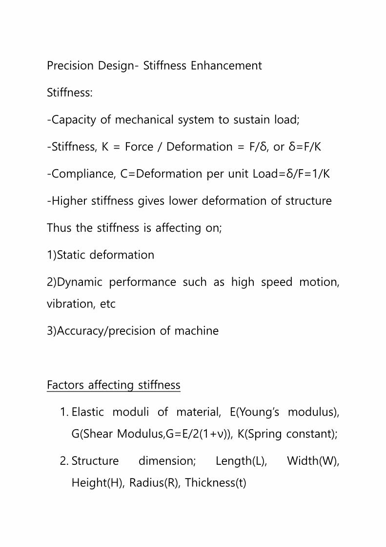
Precision Design- Stiffness Enhancement Stiffness: -Capacity of mechanical system to sustain load; -Stiffness, K = Force / Deformation = F/δ, or δ=F/K -Compliance, C=Deformation per unit Load=δ/F=1/K -Higher stiffness gives lower deformation of structure Thus the stiffness is affecting on; 1)Static deformation 2)Dynamic performance such as high speed motion, vibration, etc 3)Accuracy/precision of machine Factors affecting stiffness 1. Elastic moduli of material, E(Young’s modulus), G(Shear Modulus,G=E/2(1+ν)), K(Spring constant); 2. Structure dimension; Length(L), Width(W), Height(H), Radius(R), Thickness(t)
Transcript of Precision Design- Stiffness Enhancement
Precision Design- Stiffness Enhancement
Stiffness:
-Capacity of mechanical system to sustain load;
-Stiffness, K = Force / Deformation = F/δ, or δ=F/K
-Compliance, C=Deformation per unit Load=δ/F=1/K
-Higher stiffness gives lower deformation of structure
Thus the stiffness is affecting on;
1)Static deformation
2)Dynamic performance such as high speed motion,
vibration, etc
3)Accuracy/precision of machine
Factors affecting stiffness
1. Elastic moduli of material, E(Young’s modulus),
G(Shear Modulus,G=E/2(1+ν)), K(Spring constant);
2. Structure dimension; Length(L), Width(W),
Height(H), Radius(R), Thickness(t)
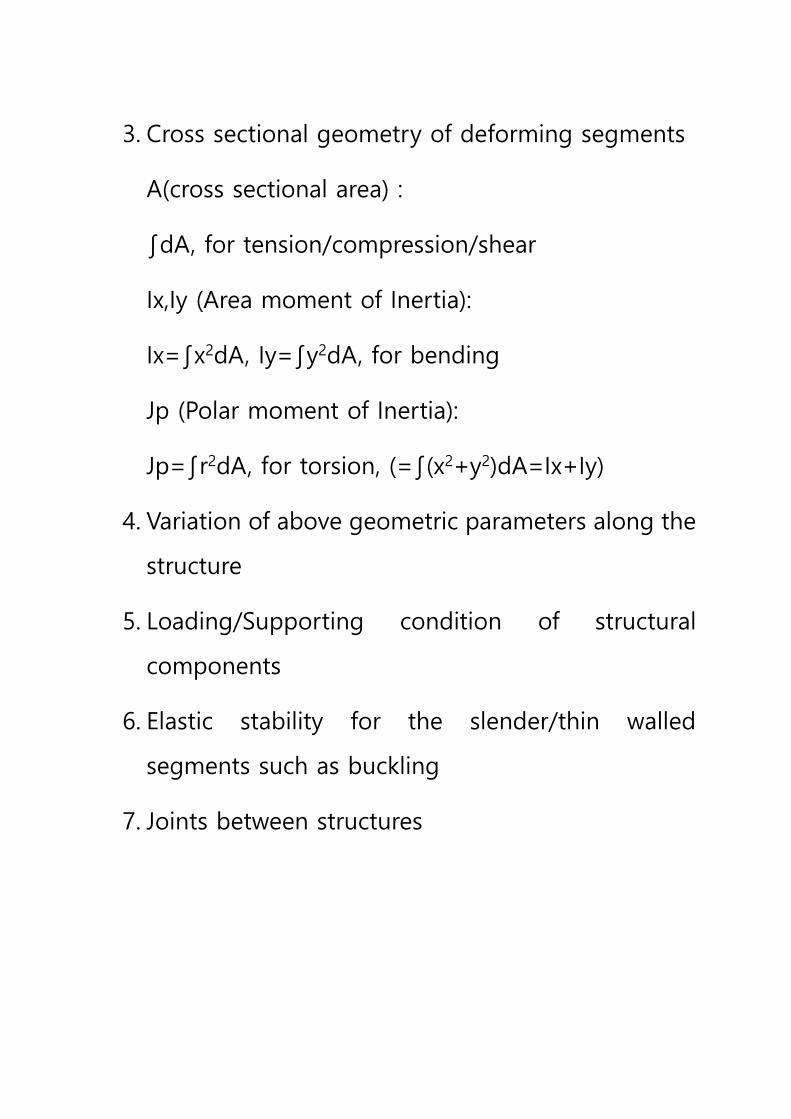
3. Cross sectional geometry of deforming segments
A(cross sectional area) :
∫dA, for tension/compression/shear
Ix,Iy (Area moment of Inertia):
Ix=∫x2dA, Iy=∫y2dA, for bending
Jp (Polar moment of Inertia):
Jp=∫r2dA, for torsion, (=∫(x2+y2)dA=Ix+Iy)
4. Variation of above geometric parameters along the
structure
5. Loading/Supporting condition of structural
components
6. Elastic stability for the slender/thin walled
segments such as buckling
7. Joints between structures
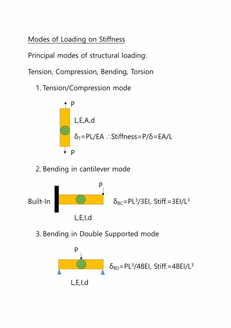
Modes of Loading on Stiffness
Principal modes of structural loading:
Tension, Compression, Bending, Torsion
1. Tension/Compression mode
P
L,E,A,d
δT=PL/EA ∴Stiffness=P/δ=EA/L
P
2. Bending in cantilever mode
P
Built-In δBC=PL3/3EI, Stiff.=3EI/L3
L,E,I,d
3. Bending in Double Supported mode
P
δBD=PL3/48EI, Stiff.=48EI/L3
L,E,I,d
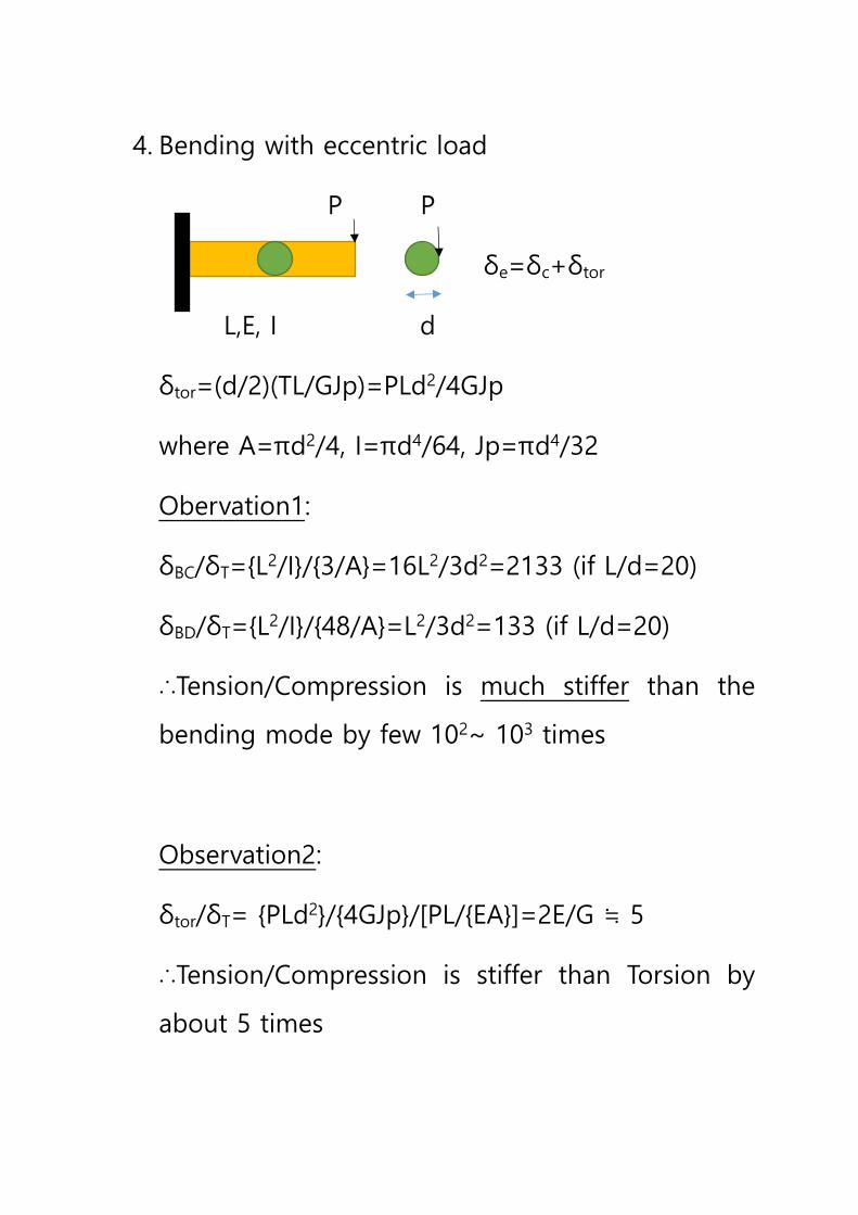
4. Bending with eccentric load
P P
δe=δc+δtor
L,E, I d
δtor=(d/2)(TL/GJp)=PLd2/4GJp
where A=πd2/4, I=πd4/64, Jp=πd4/32
Obervation1:
δBC/δT={L2/I}/{3/A}=16L2/3d2=2133 (if L/d=20)
δBD/δT={L2/I}/{48/A}=L2/3d2=133 (if L/d=20)
∴Tension/Compression is much stiffer than the
bending mode by few 102~ 103 times
Observation2:
δtor/δT= {PLd2}/{4GJp}/[PL/{EA}]=2E/G ≒ 5
∴Tension/Compression is stiffer than Torsion by
about 5 times
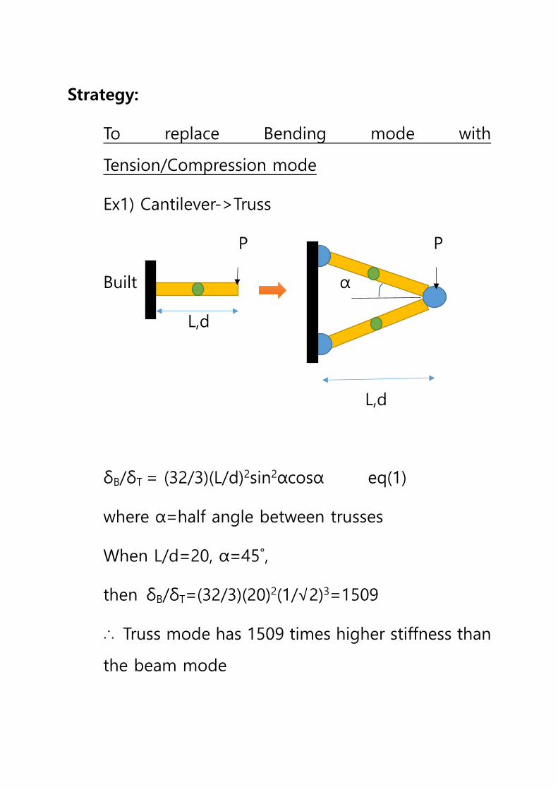
Strategy:
To replace Bending mode with
Tension/Compression mode
Ex1) Cantilever->Truss
P P
Built α
L,d
L,d
δB/δT = (32/3)(L/d)2sin2αcosα eq(1)
where α=half angle between trusses
When L/d=20, α=45˚,
then δB/δT=(32/3)(20)2(1/√2)3=1509
∴ Truss mode has 1509 times higher stiffness than
the beam mode
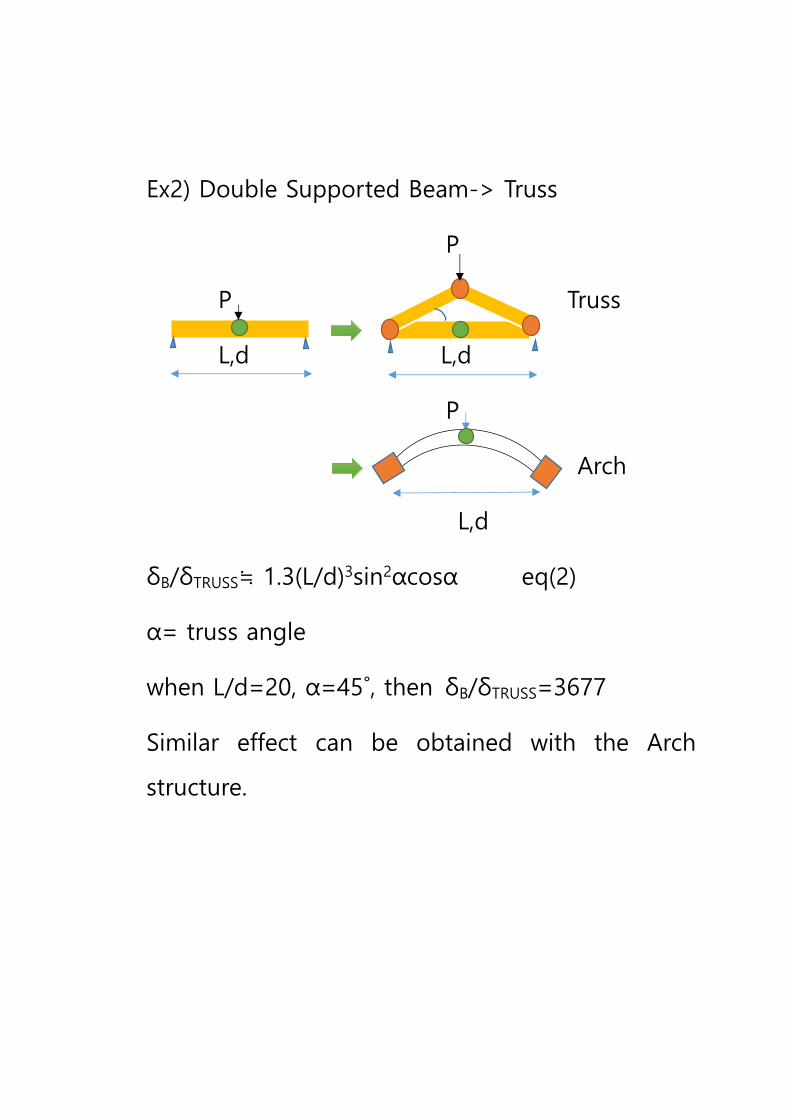
Ex2) Double Supported Beam-> Truss
P
P Truss
L,d L,d
P
Arch
L,d
δB/δTRUSS≒ 1.3(L/d)3sin2αcosα eq(2)
α= truss angle
when L/d=20, α=45˚, then δB/δTRUSS=3677
Similar effect can be obtained with the Arch
structure.
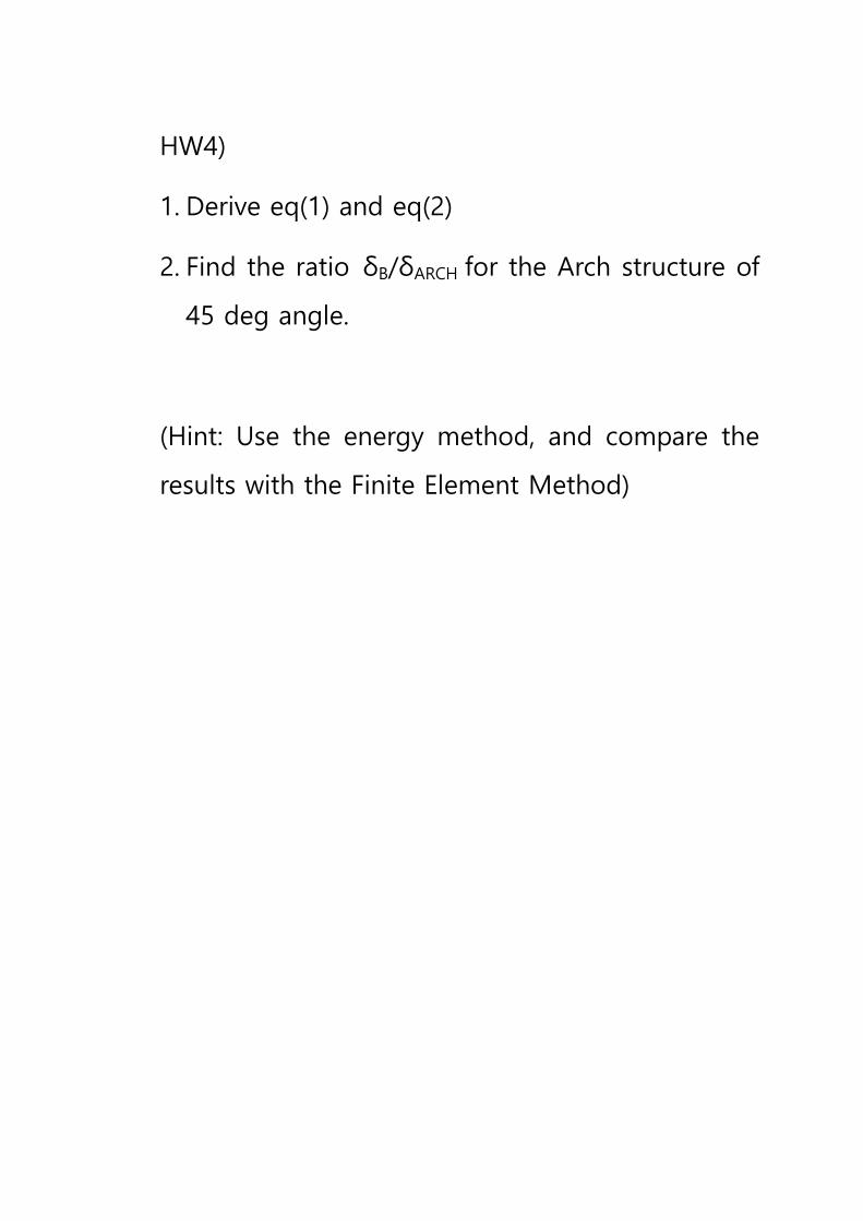
HW4)
1. Derive eq(1) and eq(2)
2. Find the ratio δB/δARCH for the Arch structure of
45 deg angle.
(Hint: Use the energy method, and compare the
results with the Finite Element Method)
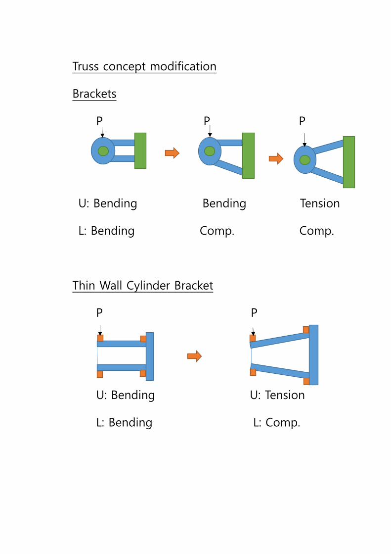
Truss concept modification
Brackets
P P P
U: Bending Bending Tension
L: Bending Comp. Comp.
Thin Wall Cylinder Bracket
P P
U: Bending U: Tension
L: Bending L: Comp.
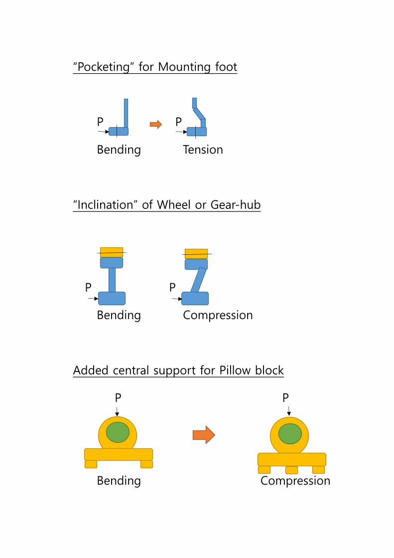
“Pocketing” for Mounting foot
P P
Bending Tension
“Inclination” of Wheel or Gear-hub
P P
Bending Compression
Added central support for Pillow block
P P
Bending Compression
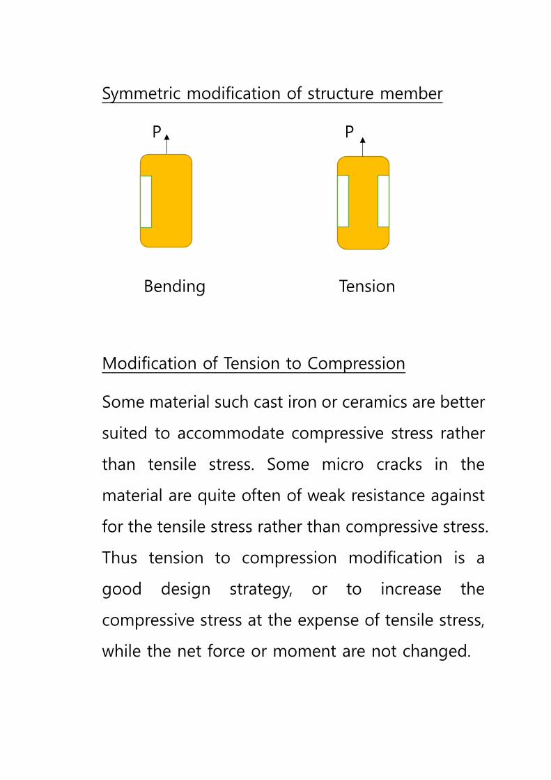
Symmetric modification of structure member
P P
Bending Tension
Modification of Tension to Compression
Some material such cast iron or ceramics are better
suited to accommodate compressive stress rather
than tensile stress. Some micro cracks in the
material are quite often of weak resistance against
for the tensile stress rather than compressive stress.
Thus tension to compression modification is a
good design strategy, or to increase the
compressive stress at the expense of tensile stress,
while the net force or moment are not changed.
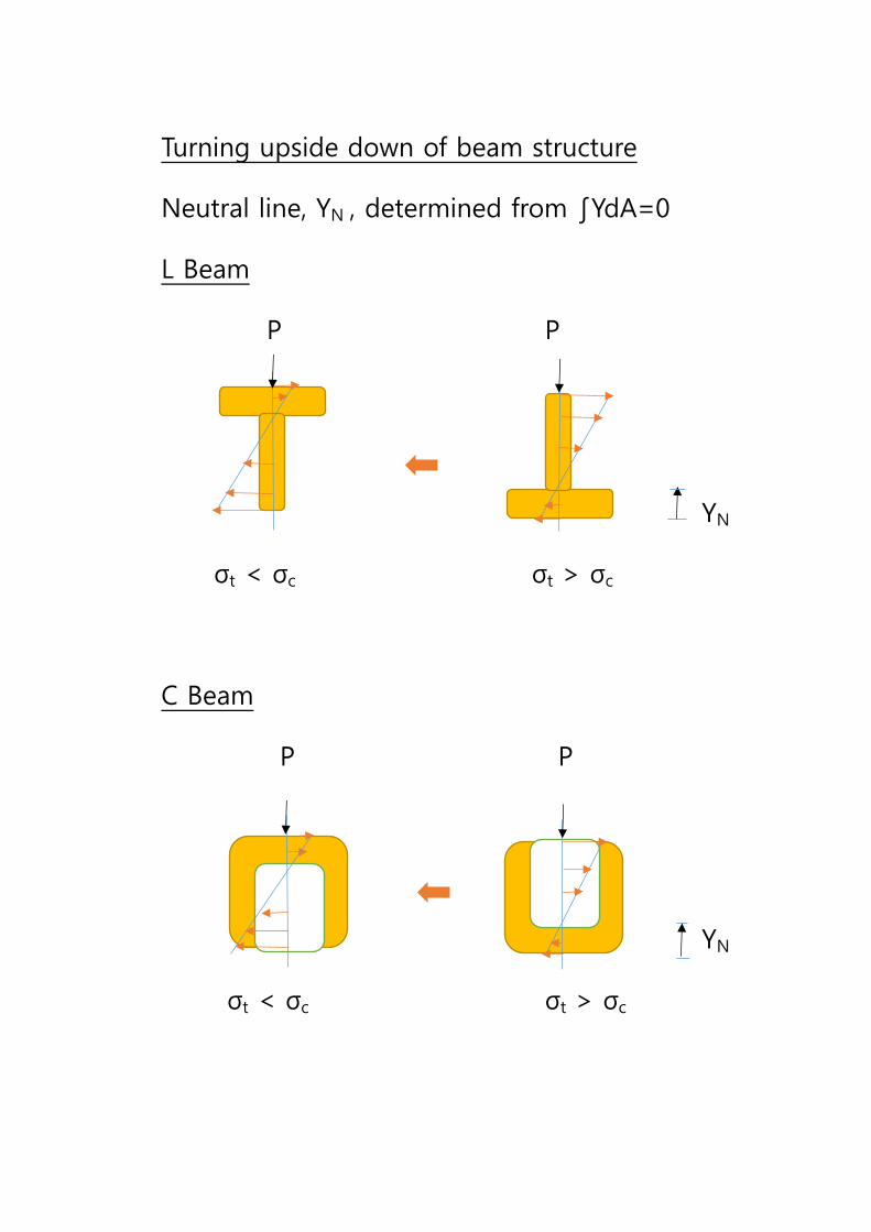
Turning upside down of beam structure
Neutral line, YN , determined from ∫YdA=0
L Beam
P P
YN
σt < σc σt > σc
C Beam
P P
YN
σt < σc σt > σc
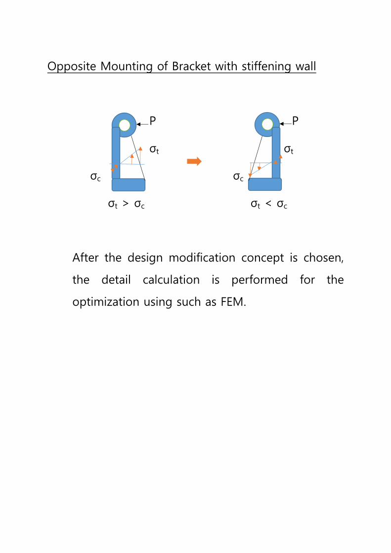
Opposite Mounting of Bracket with stiffening wall
P P
σt σt
σc σc
σt > σc σt < σc
After the design modification concept is chosen,
the detail calculation is performed for the
optimization using such as FEM.
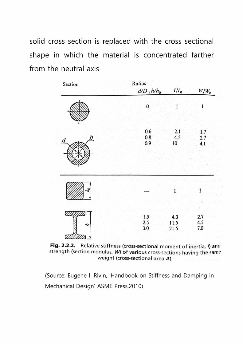
Optimization of Cross Sectional Shape
Significant gains in stiffness can be achieved
depending on the cross sectional shape.
Hollow shaft or thin walled structure have
advantage for using machine parts or robotic links
such as;
1. Very high bending or torsional stiffness/weight
ratio, minimizing the material needed
2. Light weight to reduce inertial forces and to
allow the larger payload per given sizes of
motors and actuators
3. Internal hollow provides area for electrical lines
for power and communication, hoses, control
rods, etc
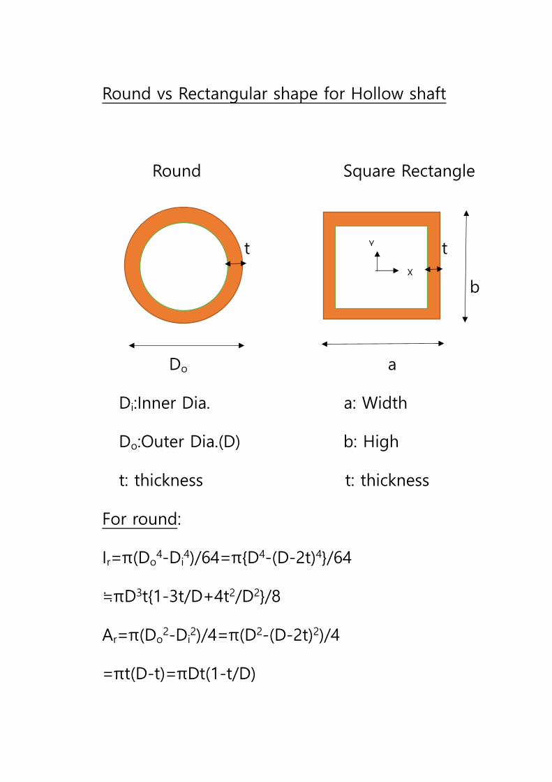
Round vs Rectangular shape for Hollow shaft
Round Square Rectangle
t t
b
Do a
Di:Inner Dia. a: Width
Do:Outer Dia.(D) b: High
t: thickness t: thickness
For round:
Ir=π(Do4-Di
4)/64=π{D4-(D-2t)4}/64
≒πD3t{1-3t/D+4t2/D2}/8
Ar=π(Do2-Di
2)/4=π(D2-(D-2t)2)/4
=πt(D-t)=πDt(1-t/D)
X
Y
For square rectangle
Ix=ab3/12-(a-2t)(b-2t)3/12
Iy=a3b/12-(a-2t)3(b-2t)/12
As=ab-(a-2t)(b-2t)=2t(a+b)-4t2
When a=b,
Is=Ix=Iy=a4/12-(a-2t)4/12
≒⅔a3t(1-3t/a+4t2/a2)
As=4ta-4t2=4ta(1-t/a)
Case1
D=a, t is the same for both shape
Is/Ir=⅔/(π/8)=1.7
As/Ar=4/π=1.27
Thus square hollow shaft gives 70% higher
bending stiffness with only 27% increase in weight
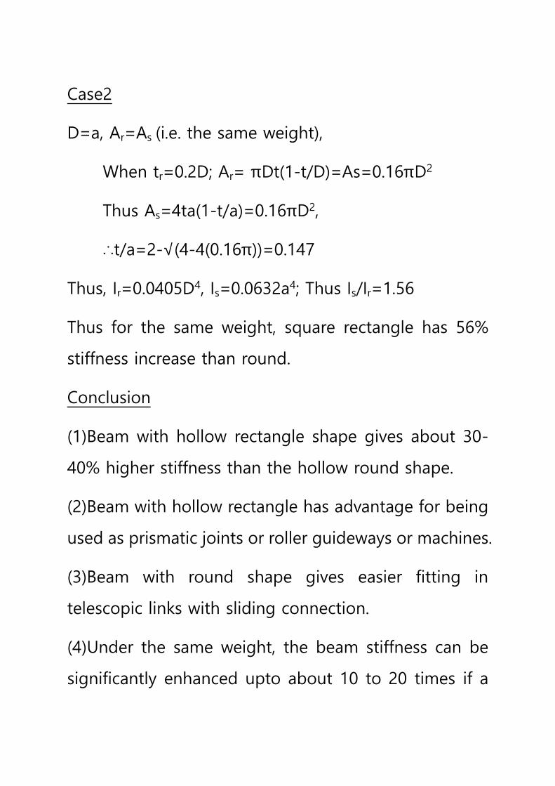
Case2
D=a, Ar=As (i.e. the same weight),
When tr=0.2D; Ar= πDt(1-t/D)=As=0.16πD2
Thus As=4ta(1-t/a)=0.16πD2,
∴t/a=2-√(4-4(0.16π))=0.147
Thus, Ir=0.0405D4, Is=0.0632a4; Thus Is/Ir=1.56
Thus for the same weight, square rectangle has 56%
stiffness increase than round.
Conclusion
(1)Beam with hollow rectangle shape gives about 30-
40% higher stiffness than the hollow round shape.
(2)Beam with hollow rectangle has advantage for being
used as prismatic joints or roller guideways or machines.
(3)Beam with round shape gives easier fitting in
telescopic links with sliding connection.
(4)Under the same weight, the beam stiffness can be
significantly enhanced upto about 10 to 20 times if a
solid cross section is replaced with the cross sectional
shape in which the material is concentrated farther
from the neutral axis
(Source: Eugene I. Rivin, ‘Handbook on Stiffness and Damping in
Mechanical Design’ ASME Press,2010)
Stiffness and Damping of Helically Patterned Tube
Helically patterned tubes are frequently used in heat
exchangers and some structural applications such as
vibration-assistant smokestacks.
Width(w) and wall thickness(t) gives very small influence
on the stiffness and damping characteristics.
Depth(h) and pitch(s) of the groove pattern are
important, and test results of brass tube approximately
show under D=16-24mm, h=0.4-1.5mm, s=8.3-24mm.
(EI)hp=(EI)s exp(-4.8(h/s))
Where (EI)s=Bending stiffness of solid tube
(EI)hp= Bending stiffness of helical patterned tube
The damping performance is also enhanced up to 7
times higher damping as shown in fig., probably due to
the stress concentration introduced by the helical
grooves, where δ indicates the logarithmetic decrement,
that is,
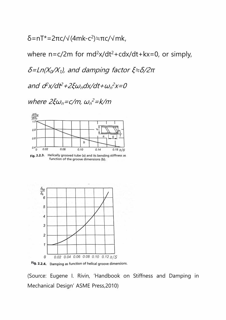
δ=nT*=2πc/√(4mk-c2)≒πc/√mk,
where n=c/2m for md2x/dt2+cdx/dt+kx=0, or simply,
δ=Ln(X0/X1), and damping factor ξ≒δ/2π
and d2x/dt2+2ξωndx/dt+ωn2x=0
where 2ξωn=c/m, ωn2=k/m
(Source: Eugene I. Rivin, ‘Handbook on Stiffness and Damping in
Mechanical Design’ ASME Press,2010)
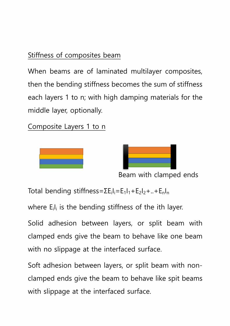
Stiffness of composites beam
When beams are of laminated multilayer composites,
then the bending stiffness becomes the sum of stiffness
each layers 1 to n; with high damping materials for the
middle layer, optionally.
Composite Layers 1 to n
Beam with clamped ends
Total bending stiffness=ΣEiIi=E1I1+E2I2+..+EnIn
where EiIi is the bending stiffness of the ith layer.
Solid adhesion between layers, or split beam with
clamped ends give the beam to behave like one beam
with no slippage at the interfaced surface.
Soft adhesion between layers, or split beam with non-
clamped ends give the beam to behave like spit beams
with slippage at the interfaced surface.