Practice Exam2 - Solutions
10
ME 351, Fluid Mechanics Spring 2014 Practice Midterm Exam 2 - Solutions Conceptual Questions (3 points each, 36 points total): 1. A table tennis ball is hit at a horizontal velocity U with a counterclockwise spin of angular velocity ω. If the ball were to travel along a horizontal path without spin, the counterclock- wise spin makes the ball travel a downward curving path instead, as shown in the figure below. The underlined statement above is (a) True; (b) False . 2. Consider the fluid transport between two large tanks as shown in the figure below. In the near-wall regions indicated by A, both inertial and viscous effects are significant and must be considered simultaneously. (a) True ; (b) False.
-
Upload
ryan-kelly -
Category
Documents
-
view
55 -
download
1
description
Solutions to the Fluid mechanics exam
Transcript of Practice Exam2 - Solutions
ME 351, Fluid Mechanics Spring 2014
Practice Midterm Exam 2 - Solutions
Conceptual Questions (3 points each, 36 points total):
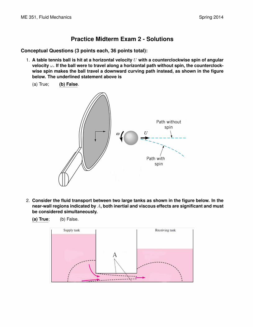
1. A table tennis ball is hit at a horizontal velocity U with a counterclockwise spin of angularvelocity ω. If the ball were to travel along a horizontal path without spin, the counterclock-wise spin makes the ball travel a downward curving path instead, as shown in the figurebelow. The underlined statement above is
(a) True; (b) False.
2. Consider the fluid transport between two large tanks as shown in the figure below. In thenear-wall regions indicated by A, both inertial and viscous effects are significant and mustbe considered simultaneously.
(a) True; (b) False.
ME 351, Fluid Mechanics Spring 2014
3. Consider a flow with a velocity field ~V =(3x2 + 2yt
)i − (6xy) j + 4k, where i, j, and k are
the x-, y-, and z-directional unit vectors of a Cartesian coordinate, respectively. The flowcan be represented by stream functions.
(a) True; (b) False.
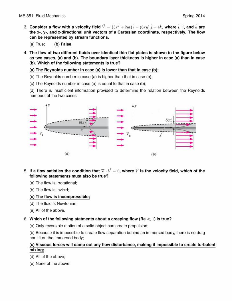
4. The flow of two different fluids over identical thin flat plates is shown in the figure belowas two cases, (a) and (b). The boundary layer thickness is higher in case (a) than in case(b). Which of the following statements is true?
(a) The Reynolds number in case (a) is lower than that in case (b);
(b) The Reynolds number in case (a) is higher than that in case (b);
(c) The Reynolds number in case (a) is equal to that in case (b);
(d) There is insufficient infomration provided to determine the relation between the Reynoldsnumbers of the two cases.
5. If a flow satisfies the condition that ∇ · ~V = 0, where ~V is the velocity field, which of thefollowing statements must also be true?
(a) The flow is irrotational;
(b) The flow is invicid;
(c) The flow is incompressible;
(d) The fluid is Newtonian;
(e) All of the above.
6. Which of the following statments about a creeping flow (Re� 1) is true?
(a) Only reversible motion of a solid object can create propulsion;
(b) Because it is impossible to create flow separation behind an immersed body, there is no dragnor lift on the immersed body;
(c) Viscous forces will damp out any flow disturbance, making it impossible to create turbulentmixing;
(d) All of the above;
(e) None of the above.
ME 351, Fluid Mechanics Spring 2014
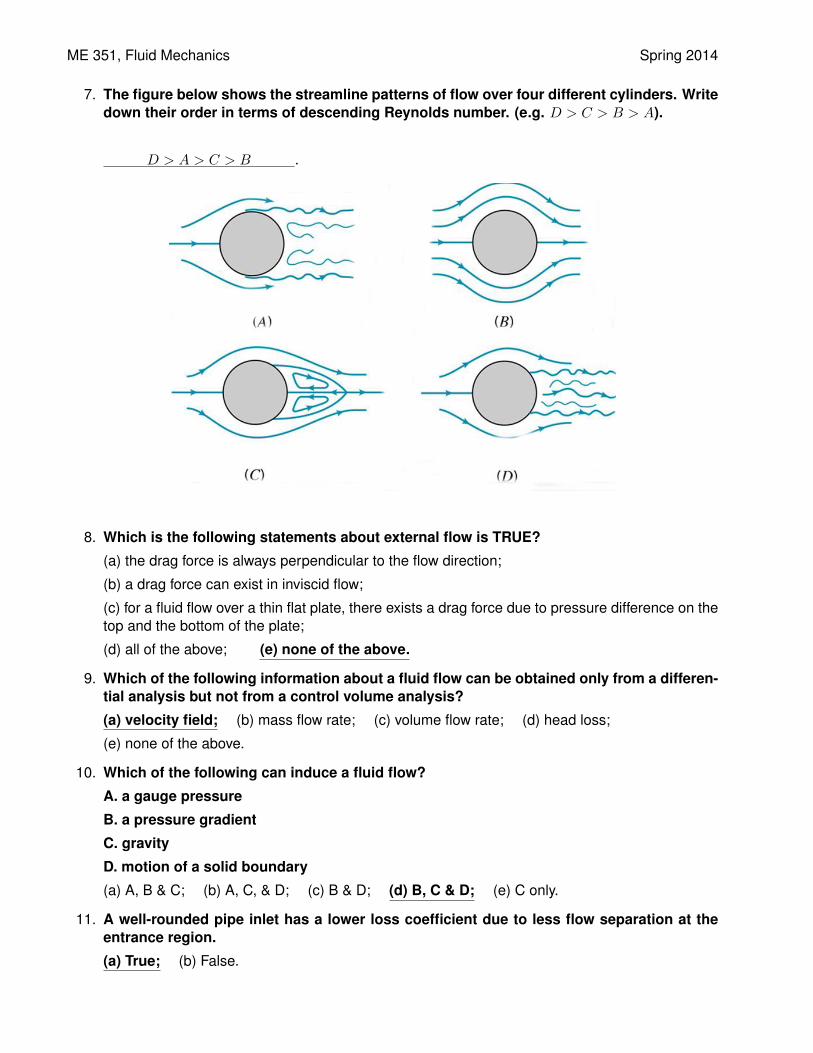
7. The figure below shows the streamline patterns of flow over four different cylinders. Writedown their order in terms of descending Reynolds number. (e.g. D > C > B > A).
D > A > C > B .
8. Which is the following statements about external flow is TRUE?
(a) the drag force is always perpendicular to the flow direction;
(b) a drag force can exist in inviscid flow;
(c) for a fluid flow over a thin flat plate, there exists a drag force due to pressure difference on thetop and the bottom of the plate;
(d) all of the above; (e) none of the above.
9. Which of the following information about a fluid flow can be obtained only from a differen-tial analysis but not from a control volume analysis?
(a) velocity field; (b) mass flow rate; (c) volume flow rate; (d) head loss;
(e) none of the above.
10. Which of the following can induce a fluid flow?
A. a gauge pressure
B. a pressure gradient
C. gravity
D. motion of a solid boundary
(a) A, B & C; (b) A, C, & D; (c) B & D; (d) B, C & D; (e) C only.
11. A well-rounded pipe inlet has a lower loss coefficient due to less flow separation at theentrance region.
(a) True; (b) False.
ME 351, Fluid Mechanics Spring 2014
12. Which is the following statements about an airfoil is TRUE?
(a) when calculating the lift of an airfoil, the frontal area should be used;
(b) to maximize lift and minimize drag, a large angle of attack should be used as much as possibleduring a flight;
(c) flaps are used to decrease the drag generated by an airfoil at a given flying speed;
(d) an airfoil loses significant lift when stalling at a large angle of attack due to large flow
separation;
(e) none of the above.
Analytical Problems (15 points each, 60 points total):
Additional Information:Water: ρ = 1000 kg/m3, µ = 1.003× 10⁻³ kg/m·s.Air: ρ = 1.269 kg/m3, µ = 1.754× 10⁻⁵ kg/m·s.Gravitational acceleration: g = 9.81 m/s2.
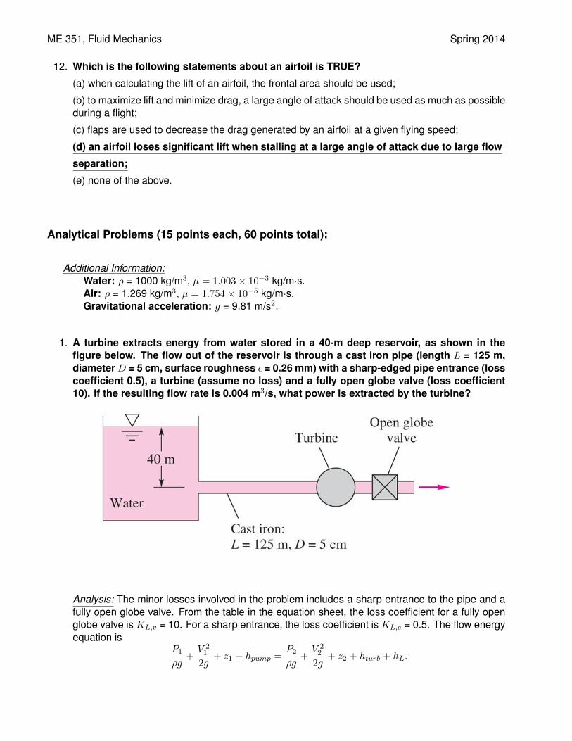
1. A turbine extracts energy from water stored in a 40-m deep reservoir, as shown in thefigure below. The flow out of the reservoir is through a cast iron pipe (length L = 125 m,diameterD = 5 cm, surface roughness ε = 0.26 mm) with a sharp-edged pipe entrance (losscoefficient 0.5), a turbine (assume no loss) and a fully open globe valve (loss coefficient10). If the resulting flow rate is 0.004 m3/s, what power is extracted by the turbine?
Analysis: The minor losses involved in the problem includes a sharp entrance to the pipe and afully open globe valve. From the table in the equation sheet, the loss coefficient for a fully openglobe valve is KL,v = 10. For a sharp entrance, the loss coefficient is KL,e = 0.5. The flow energyequation is
P1
ρg+V 21
2g+ z1 + hpump =
P2
ρg+V 22
2g+ z2 + hturb + hL.
ME 351, Fluid Mechanics Spring 2014
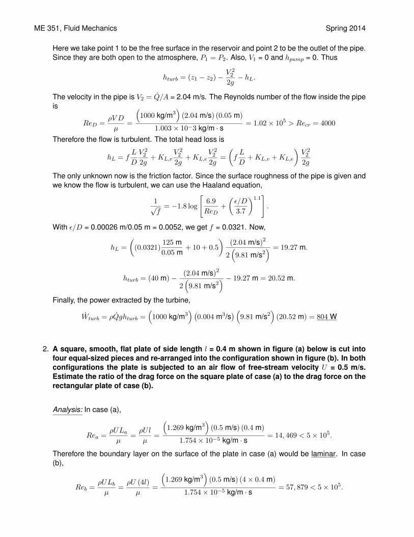
Here we take point 1 to be the free surface in the reservoir and point 2 to be the outlet of the pipe.Since they are both open to the atmosphere, P1 = P2. Also, V1 = 0 and hpump = 0. Thus
hturb = (z1 − z2)−V 22
2g− hL.
The velocity in the pipe is V2 = Q/A = 2.04 m/s. The Reynolds number of the flow inside the pipeis
ReD =ρV D
µ=
(1000 kg/m3
)(2.04 m/s) (0.05 m)
1.003× 10⁻³ kg/m · s= 1.02× 10⁵ > Recr = 4000
Therefore the flow is turbulent. The total head loss is
hL = fL
D
V 22
2g+KL,v
V 22
2g+KL,e
V 22
2g=
(fL
D+KL,v +KL,e
)V 22
2g
The only unknown now is the friction factor. Since the surface roughness of the pipe is given andwe know the flow is turbulent, we can use the Haaland equation,
1√f= −1.8 log
[6.9
ReD+
(ε/D
3.7
)1.1].
With ε/D = 0.00026 m/0.05 m = 0.0052, we get f = 0.0321. Now,
hL =
((0.0321)
125 m0.05 m
+ 10 + 0.5
)(2.04 m/s)2
2(9.81 m/s2
) = 19.27 m.
hturb = (40 m)− (2.04 m/s)2
2(9.81 m/s2
) − 19.27 m = 20.52 m.
Finally, the power extracted by the turbine,
Wturb = ρQghturb =(1000 kg/m3
) (0.004 m3/s
) (9.81 m/s2
)(20.52 m) = 804 W
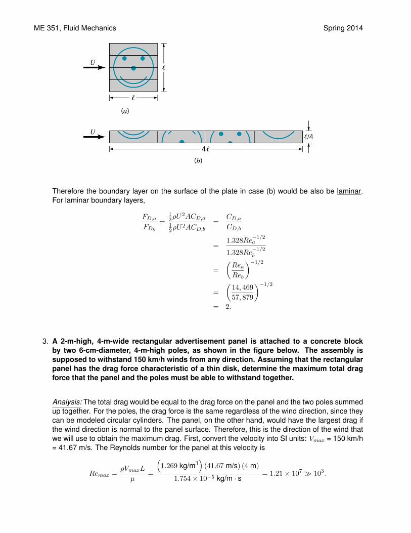
2. A square, smooth, flat plate of side length l = 0.4 m shown in figure (a) below is cut intofour equal-sized pieces and re-arranged into the configuration shown in figure (b). In bothconfigurations the plate is subjected to an air flow of free-stream velocity U = 0.5 m/s.Estimate the ratio of the drag force on the square plate of case (a) to the drag force on therectangular plate of case (b).
Analysis: In case (a),
Rea =ρULaµ
=ρUl
µ=
(1.269 kg/m3
)(0.5 m/s) (0.4 m)
1.754× 10⁻⁵ kg/m · s= 14, 469 < 5× 10⁵.
Therefore the boundary layer on the surface of the plate in case (a) would be laminar. In case(b),
Reb =ρULbµ
=ρU (4l)
µ=
(1.269 kg/m3
)(0.5 m/s) (4× 0.4 m)
1.754× 10⁻⁵ kg/m · s= 57, 879 < 5× 10⁵.
ME 351, Fluid Mechanics Spring 2014
Therefore the boundary layer on the surface of the plate in case (b) would be also be laminar.For laminar boundary layers,
FD,aFDb
=12ρU
2ACD,a12ρU
2ACD,b=
CD,aCD,b
=1.328Re
−1/2a
1.328Re−1/2b
=
(ReaReb
)−1/2
=
(14, 469
57, 879
)−1/2
= 2.
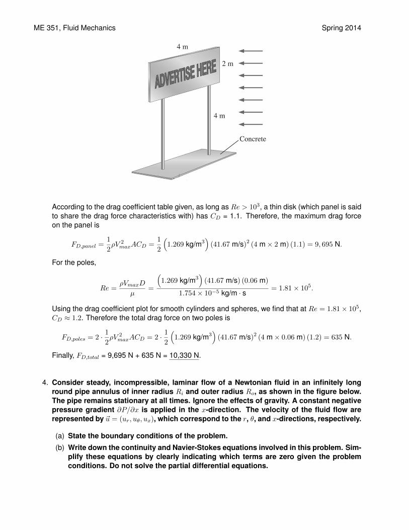
3. A 2-m-high, 4-m-wide rectangular advertisement panel is attached to a concrete blockby two 6-cm-diameter, 4-m-high poles, as shown in the figure below. The assembly issupposed to withstand 150 km/h winds from any direction. Assuming that the rectangularpanel has the drag force characteristic of a thin disk, determine the maximum total dragforce that the panel and the poles must be able to withstand together.
Analysis: The total drag would be equal to the drag force on the panel and the two poles summedup together. For the poles, the drag force is the same regardless of the wind direction, since theycan be modeled circular cylinders. The panel, on the other hand, would have the largest drag ifthe wind direction is normal to the panel surface. Therefore, this is the direction of the wind thatwe will use to obtain the maximum drag. First, convert the velocity into SI units: Vmax = 150 km/h= 41.67 m/s. The Reynolds number for the panel at this velocity is
Remax =ρVmaxL
µ=
(1.269 kg/m3
)(41.67 m/s) (4 m)
1.754× 10⁻⁵ kg/m · s= 1.21× 10⁷ � 103.
ME 351, Fluid Mechanics Spring 2014
According to the drag coefficient table given, as long as Re > 103, a thin disk (which panel is saidto share the drag force characteristics with) has CD = 1.1. Therefore, the maximum drag forceon the panel is
FD,panel =1
2ρV 2
maxACD =1
2
(1.269 kg/m3
)(41.67 m/s)2 (4 m× 2 m) (1.1) = 9, 695 N.
For the poles,
Re =ρVmaxD
µ=
(1.269 kg/m3
)(41.67 m/s) (0.06 m)
1.754× 10⁻⁵ kg/m · s= 1.81× 10⁵.
Using the drag coefficient plot for smooth cylinders and spheres, we find that at Re = 1.81× 10⁵,CD ≈ 1.2. Therefore the total drag force on two poles is
FD,poles = 2 · 12ρV 2
maxACD = 2 · 12
(1.269 kg/m3
)(41.67 m/s)2 (4 m× 0.06 m) (1.2) = 635 N.
Finally, FD,total = 9,695 N + 635 N = 10,330 N.
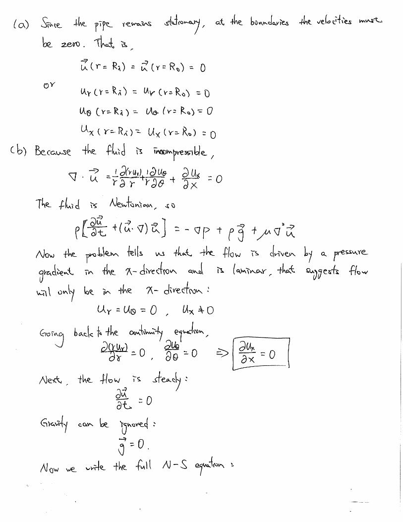
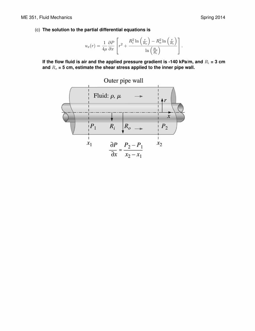
4. Consider steady, incompressible, laminar flow of a Newtonian fluid in an infinitely longround pipe annulus of inner radius Ri and outer radius Ro, as shown in the figure below.The pipe remains stationary at all times. Ignore the effects of gravity. A constant negativepressure gradient ∂P/∂x is applied in the x-direction. The velocity of the fluid flow arerepresented by ~u = (ur, uθ, ux), which correspond to the r, θ, and x-directions, respectively.
(a) State the boundary conditions of the problem.
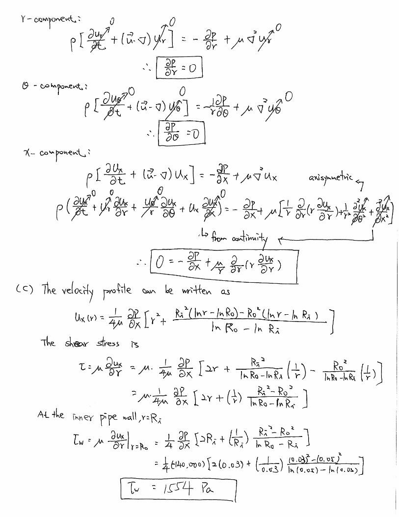
(b) Write down the continuity and Navier-Stokes equations involved in this problem. Sim-plify these equations by clearly indicating which terms are zero given the problemconditions. Do not solve the partial differential equations.
ME 351, Fluid Mechanics Spring 2014
(c) The solution to the partial differential equations is
ux(r) =1
4µ
∂P
∂x
r2 + R2i ln
(rRo
)−R2
o ln(rRi
)ln(RoRi
) .
If the flow fluid is air and the applied pressure gradient is -140 kPa/m, and Ri = 3 cmand Ro = 5 cm, estimate the shear stress applied to the inner pipe wall.