POWERPACK - Nireco pipe hydraulic pressure MPa 1 1.2 1.2 0.8 Diameter of jet pip mm 2.0 1.6 1.6...
4
MODEL AJ11,AJ21,AJ41 POWERPACK The Powerpack is an actuator that controls a load such as a valve. As its output shaft performs rotary motions it is suitable for controlling a final control element of rotary type such as a butterfly valve.
Transcript of POWERPACK - Nireco pipe hydraulic pressure MPa 1 1.2 1.2 0.8 Diameter of jet pip mm 2.0 1.6 1.6...
MODEL AJ11,AJ21,AJ41POWERPACK
The Powerpack is an actuator that controls a load such as a valve. As its output shaft performs rotary motions it is suitable for controlling a final control element of rotary type such as a butterfly valve.
2
INTRODUCTIONThe Powerpack is a kind of an electro-hydraulic actuator.It is of the proportional positioning type and has a hydraulic work piston that is proportional to the electrical system, with the function of converting a DC electrical signal (DC 4-20mA) into a motion of the hydraulic work piston.The Powerpack is of a structure that unitizes the current- hydraulic pressure converter unit, the hydraulic pump and the work cylinder, and it does not require external piping.
FEATURES●Usable as an actuator for various electronic controllers.●The actuating speed is high and a large actuating force can be obtained because actuation is performed by using hydraulic pressure on reception of an electrical signal.●Maintenance is easy and reliability is high because of a moving coil system incorporating a hydraulic jet pipe and a stable permanent magnet.●As the casing serves as an oil tank and all parts are contained in the interior, no external piping is required.
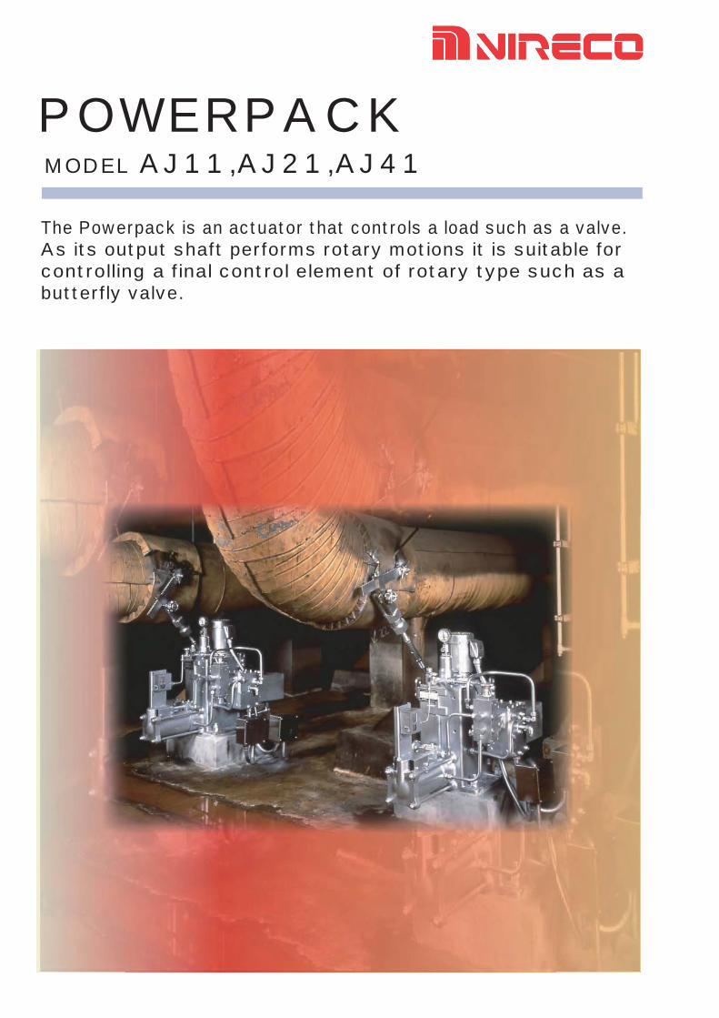
SPECIFICATIONSGeneral specifications
Input signal…………………………… DC 4 to 20mAResistance of moving coil … 470Ω+0Ω/-50Ω(at25℃)Floating band……………………………………… 15%Linearity……………………………………………±2%Maximum crank arm rotation……………… 60 degreesLength of crank arm…………………………… 300mmControl action……………………… Proportional actionOperating directionNormal: Crank arm turns counterclockwise with input signal up.Reverse: Crank arm turns clockwise with input signal up.Installation……………………………………HorizontalHydraulic oil temperature…………………+10 to+ 70℃Paint color…………………………………………Silver
Specifications by model
Model AJ21 AJ41 AJ1150Hz 60Hz
Motor kW 0.4 0.75 1.5Max.Operating torquekN・m
Max 1.42 1.71 2.15 4.12 Min. 1.02 1.23 1.53 2.95
Max.speed with no load degree/sec 2.4 7 8.5Max. operating pressure MPa 1 1.2 1.2 2.3Jet pipe hydraulic pressure MPa 1 1.2 1.2 0.8Diameter of jet pip mm 2.0 1.6 1.6Auxiliary piston NoneCylinder dia.x stroke mm φ125×150 φ125×150 φ125×150Hystresis error (no load) % 1 1 1Overshooting (no load ) % 1 1 1Amount of oil required 27(w/ACC:34) 27(w/ACC:34) 27(w/ACC:34)Hydraulic pump type Fixed VariableRotating direction of motor Reverse Normal
Mass. (including oil) kg 175 180 195Ambient temperature ℃ -20~+55 -20~+55 -20~+60
With CV2 With CV2
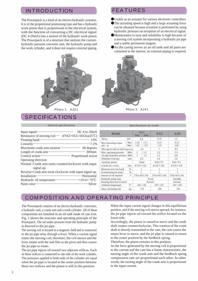
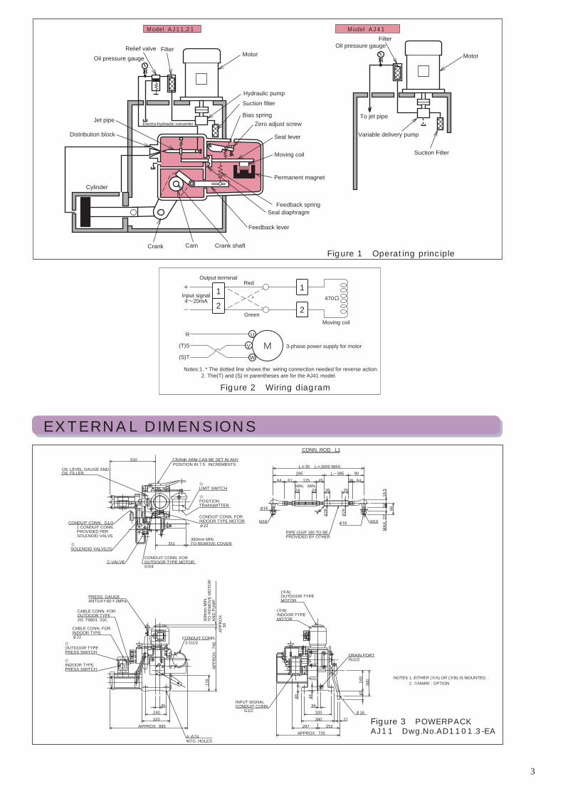
COMPOSITION AND OPERATING PRINCIPLEThe Powerpack consists of an electro-hydraulic converter,a hydraulic unit, a crank unit and a work cylinder. All of these components are installed in an oil tank made of cast iron.Fig. 1 shows the structure and operating principle of the Powerpack. The oil under pressure from the hydraulic pump is directed to the jet pipe.The moving coil is located in a magnetic field and is connectedto the jet pipe relay through a lever. When a current signal enters the moving coil, therefore, the coil moves and the lever rotates with the seal film as the pivot and thus causes the jet pipe to rotate.The jet pipe injects oil toward two adjacent orifices. Each of these orifices is connected to one side of the work cylinder. The pressures applied to both ends of the cylinder are equal when the jet pipe is located in the center position between these two orifices and the piston is still in this position.
When the input current signal changes in this equilibrium position, and if the moving coil moves upward, for instance, the jet pipe injects oil toward the orifice located on the lower side.Accordingly, the piston is caused to move and the crank shaft rotates counterclockwise. This rotation of the crank shaft is directly transmitted to the cam, the cam causes the return lever to move, and the jet pipe is caused to return to the center position by the feedback spring. Therefore, the piston remains in this position.As the force generated by the moving coil is proportional to the current and the cam has a linear characteristic, the turning angle of the crank arm and the feedback spring compression rate are proportional each other. In other words, the turning angle of the crank arm is proportional to the input current.
Photo 1 AJ21 Photo 2 AJ41
3
Figure 1 Operating principle
Output terminalRed
Green
* 470Ω
Moving coil
Input signal4~20mA
+
-
1 1
2 2
MU
V 3-phase power supply for motor
R
(S)T
(T)S
W
Figure 2 Wiring diagram
Notes:1. * The dotted line shows the wiring connection needed for reverse action.2. The(T) and (S) in parentheses are for the AJ41 model.
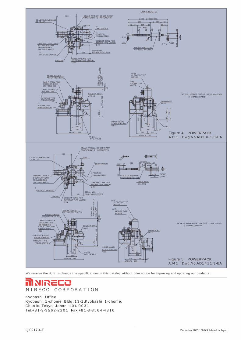
EXTERNAL DIMENSIONS
Figure 3 POWERPACKAJ11 Dwg.No.AD1101.3-EA
NOTES 1. EITHER (※A) OR (※B) IS MOUNTED. 2. ☆MARK : OPTION
CONN. ROD L1
φ26
φ26
45 26
66M
AX. 2
219
.5
φ16
φ16
24 24 35 35
L-385L±35 L=2000 MAX.
295 9064 61 125 64
MIN.
300m
m M
IN.
TO R
EMO
VE M
OTO
RAN
D P
UM
P
☆
530
351
☆
☆ MIN.
24
42
252APPROX. 735
297380320
34
21
40 45
30024
0
☆
☆
320240
45
178
APPR
OX.
740
APPR
OX.
30
APPROX. 895
LIMIT SWITCH
POSITION TRANSMITTER
(※A)OUTDOOR TYPEMOTOR
PIPE (SGP 1B) TO BEPROVIDED BY OTHER
M16M16
CRANK ARM CAN BE SET IN ANYPOSITION IN 7.5゚ INCREMENTS
CONDUIT CONN. G1/21 CONDUIT CONN.PROVIDED PERSOLENOID VALVE
SOLENOID VALVE(S)
OIL LEVEL GAUGE ANDOIL FILLER
C-VALVECONDUIT CONN. FOROUTDOOR TYPE MOTORG3/4
CONDUIT CONN. FORINDOOR TYPE MOTORφ22
300mm MIN.TO REMOVE COVER
(※B)INDOOR TYPEMOTOR
φ16
DRAIN PORTRc1/2
INPUT SIGNALCONDUIT CONN.
G1/2
CONDUIT CONN.2-G1/2
PRESS. GAUGEANT1/4×60×3MPa
CABLE CONN. FOROUTDOOR TYPEJIS F8801 20C
OUTDOOR TYPEPRESS SWITCH
INDOOR TYPEPRESS SWITCH
CABLE CONN. FORINDOOR TYPEφ22
4-φ24MTG. HOLES
Motor
Model AJ11,21
Relief valve Filter Oil pressure gauge
Jet pipe
Distribution block
Cylinder
Electro-hydraulic converter
Crank Crank shaft
Feedback lever
Seal diaphragm
Cam
Feedback spring
Permanent magnet
Moving coil
Seal lever
Zero adjust screwBias spring
Suction filterHydraulic pump
Motor
Variable delivery pump
Suction Filter
To jet pipe
Oil pressure gaugeFilter
Model AJ41
December 2005 100 KS Printed in JapanQI0217.4-E
Figure 4 POWERPACKAJ21 Dwg.No.AD1301.3-EA
CONN. ROD L1
φ26
φ26
24
45 26
66M
AX. 2
219
.5
φ16
φ16
24 24 35 35
L-385L±35 L=2000 MAX.
295 9064 61 125 64
MIN.
42
252APPROX. 735
297380320
34
21
40 45
320240
45
300m
m M
IN.
TO R
EMO
VE M
OTO
RAN
D P
UM
P17
8AP
PRO
X. 7
50AP
PRO
X.30
530
APPROX. 895
351
☆
☆
30024
0
MIN.
NOTES 1. EITHER (※A) OR (※B) IS MOUNTED. 2. ☆MARK : OPTION
LIMIT SWITCH
POSITION TRANSMITTER
(※A)OUTDOOR TYPEMOTOR
CONDUIT CONN.2-G1/2
(※B)INDOOR TYPEMOTOR
PIPE (SGP 1B) TO BEPROVIDED BY OTHER
M16M16
φ16
DRAIN PORTRc1/2
INPUT SIGNALCONDUIT CONN.G1/2
CABLE CONN. FOROUTDOOR TYPEJIS F8801 20C
OUTDOOR TYPEPRESS SWITCH
INDOOR TYPEPRESS SWITCH
CABLE CONN. FORINDOOR TYPEφ22
4-φ24MTG. HOLES
CRANK ARM CAN BE SET IN ANYPOSITION IN 7.5゚ INCREMENTS
CONDUIT CONN. G1/21 CONDUIT CONN.PROVIDED PERSOLENOID VALVE
SOLENOID VALVE(S)
OIL LEVEL GAUGE ANDOIL FILLER
C-VALVECONDUIT CONN. FOROUTDOOR TYPE MOTORG3/4
CONDUIT CONN. FORINDOOR TYPE MOTORφ22
300mm MIN.TO REMOVE COVER
PRESS. GAUGEANT1/4×60×3MPa
☆
☆
☆
☆
☆
25
φ20 512 MAX.2700157115
25
77
φ20h7
5028
45240320
895
178
780
40
34
297 265 52800
4540
4261
240
30026
351
530
φ20
320380
CONN. RODGE1200.2
Rc2
(HOLE)(SHAFT)PIPE (SGP 2B) TO BE
PROVIDED BY OTHER
APPROX.
NOTES 1. EITHER (※A)OR(※B) IS MOUNTED. 2. ☆ MARK : OPTION
C-VALVECONDUIT CONN. FOROUTDOOR TYPE MOTORG3/4
APPROX.
APPR
OX.
APPR
OX.30
0mm
MIN
.TO
REM
OVE
MO
TOR
AND
PU
MP
PRESS. GAUGEANT1/4×60×5MPa
PRESS. GAUGEANT1/4×60×3MPa
CABLE CONN. FOROUTDOOR TYPEJIS F8801 20CCABLE CONN. FORINDOOR TYPEφ22
OUTDOOR TYPEPRESS. SWITCHINDOOR TYPEPRESS. SWITCH
CONDUIT CONN.2-G1/2
4-φ24MTG. HOLES
INPUT SIGNALCONDUIT CONN.G1/2
DRAIN PORTRc1/2
OUTDOOR TYPEMOTOR
INDOOR TYPEMOTOR
(※A)
(※B)
SOLENOID VALVE(S)300mm MIN.TO REMOVE COVER
OIL LEVEL GAUGE ANDOIL FILLER
CONDUIT CONN. G1/21 CONDUIT CONN.PROVIDED PERSOLENOID VALVE
CRANK ARM CAN BE SET IN ANYPOSITION IN 7.5°INCREMENTS
LIMIT SWITCH
POSITIONTRANSMITTER
CONDUIT CONN. FORINDOOR TYPE MOTORφ28
R23
Figure 5 POWERPACKAJ41 Dwg.No.AD1411.3-EA
Kyobashi OfficeKyobashi 1-chome Bldg.,13-1,Kyobashi 1-chome,Chuo-ku,Tokyo Japan 104-0031Tel:+81-3-3562-2201 Fax:+81-3-3564-4316
We reserve the right to change the specifications in this catalog without prior notice for improving and updating our products.
NIRECO CORPORATION
☆
☆
☆