Power Electronics No. 11: Chopper circuit with a braking ...
15
Power Electronics No. 11: Chopper circuit with a braking function Takeshi Furuhashi Furuhashi_at_cse.nagoya-u.ac.jp 1
Transcript of Power Electronics No. 11: Chopper circuit with a braking ...
Power Electronics No. 11: Chopper circuit with
a braking function
Takeshi Furuhashi Furuhashi_at_cse.nagoya-u.ac.jp
1
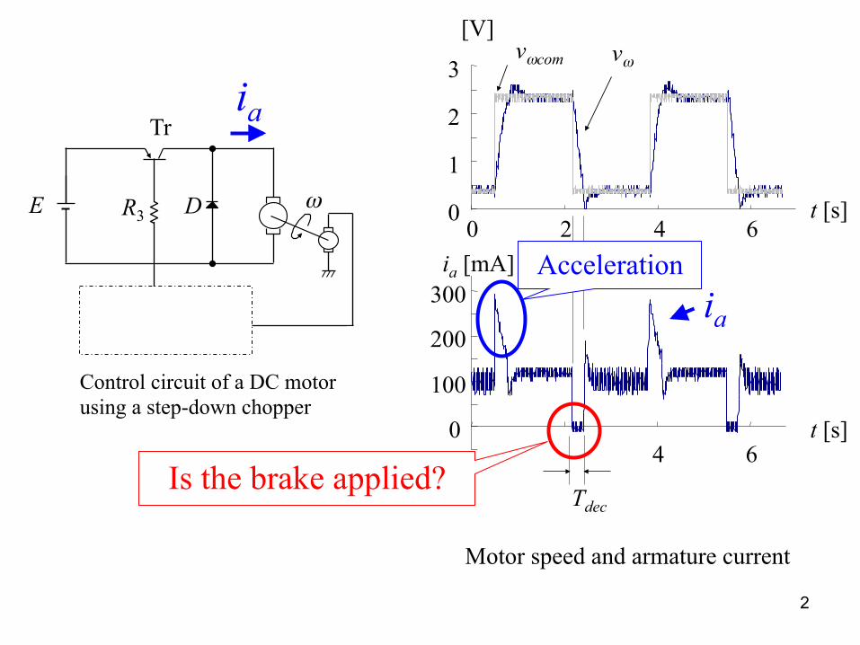
Control circuit of a DC motor using a step-down chopper
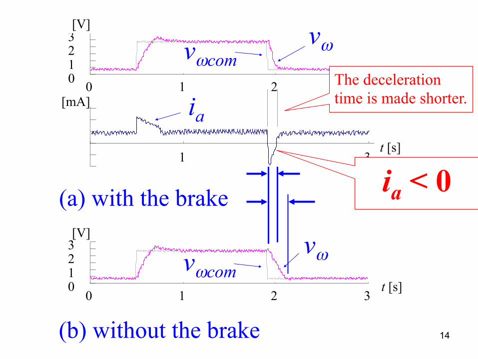
Motor speed and armature current
1
2
3
2 4 6 0
0
vω
t [s]
vωcom
0
100
200
300
4 6
[V]
t [s]
ia [mA]
Tdec
ω
Tr
D E R3
ia
ia
Acceleration
Is the brake applied?
2
ω
Tr
D E R3
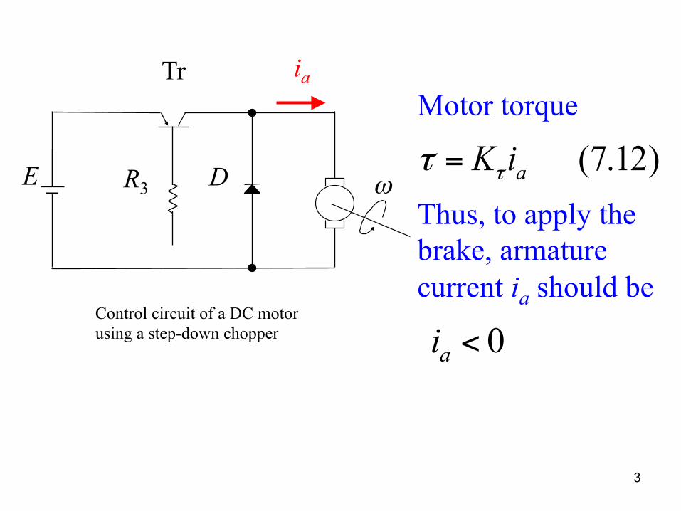
ia Motor torque Thus, to apply the brake, armature current ia should be
3
Control circuit of a DC motor using a step-down chopper
(7.12) aiKττ =
0 <ai
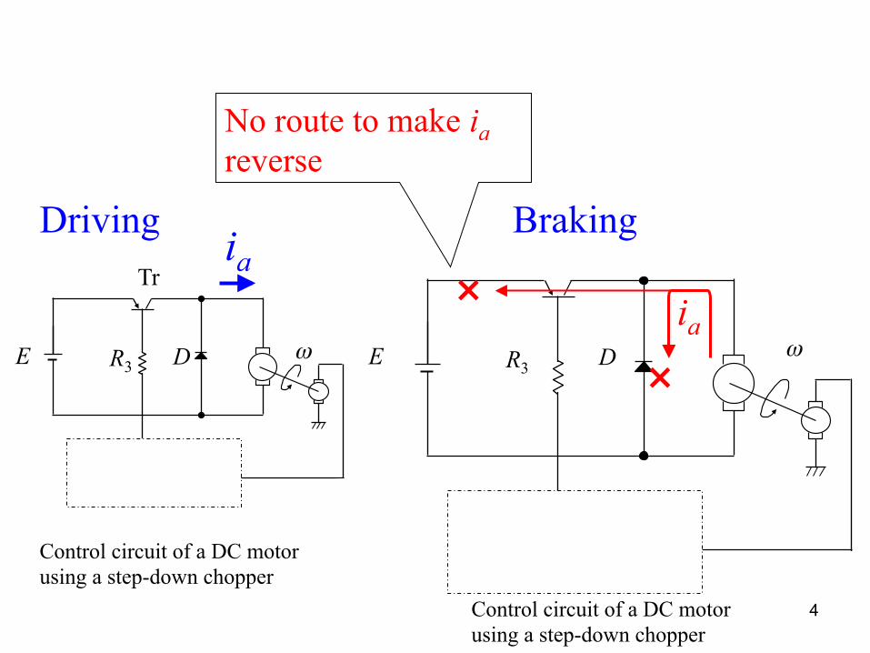
ωD E R3
No route to make ia reverse
Braking Driving
4
Control circuit of a DC motor using a step-down chopper
ω
Tr
D E R3
ia
Control circuit of a DC motor using a step-down chopper
ia
×
×
Ra
La
Ea
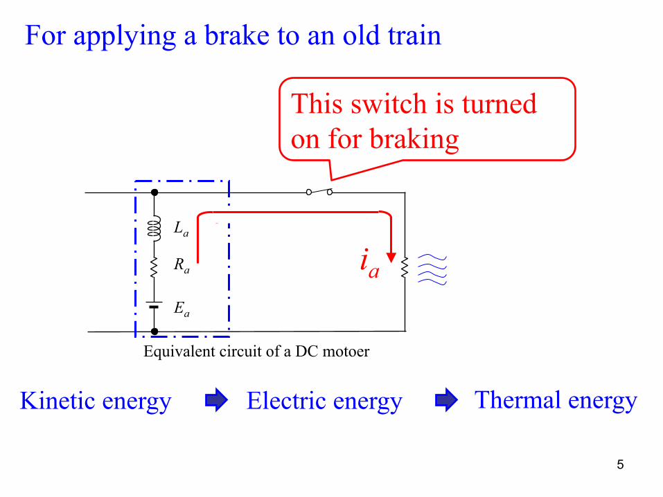
Equivalent circuit of a DC motoer
For applying a brake to an old train
This switch is turned on for braking
5
Thermal energy Kinetic energy Electric energy
ia
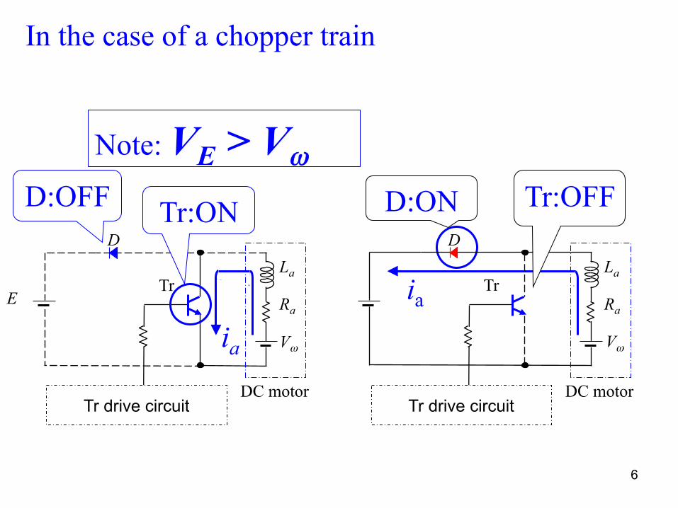
In the case of a chopper train
6
Note: VE > Vω
Ra
La
Tr drive circuit
Tr E
D
ia
DC motor
Tr:ON D:OFF
Vω Vω
Ra
La
Tr drive circuit
Tr
D
ia
DC motor
D:ON Tr:OFF
E + C
R
LED
VE Tr
L D
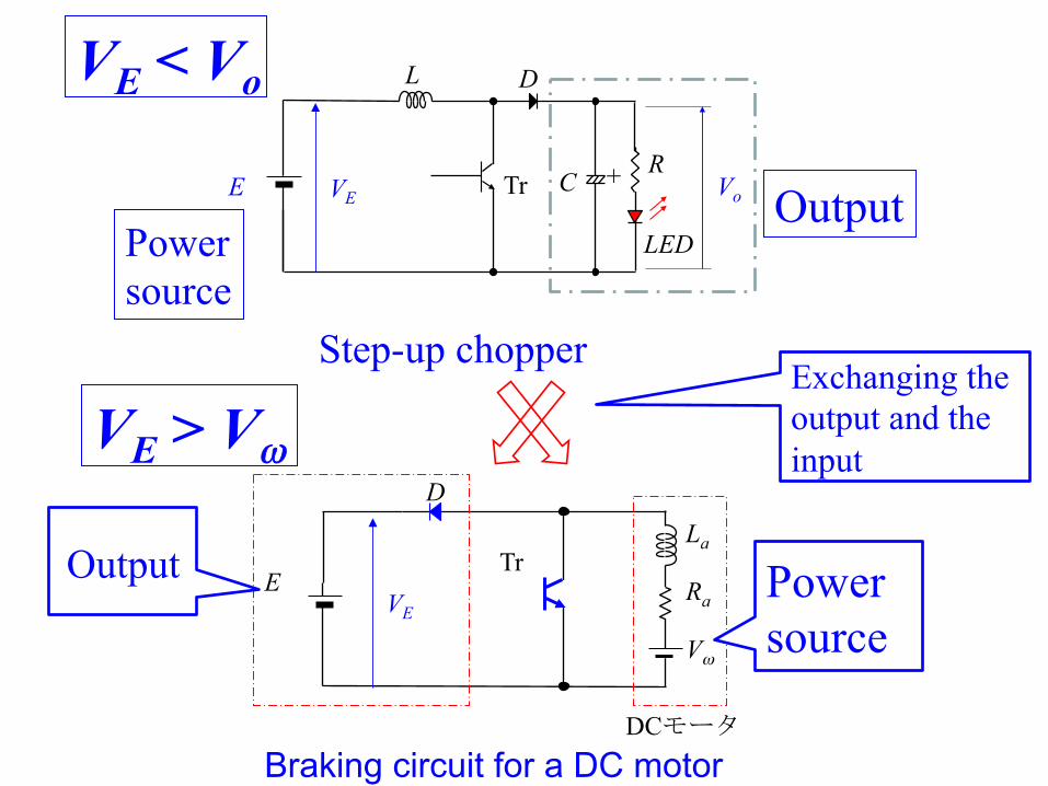
Step-up chopper
Vo
Ra
La
Vω
Tr E
D
DCモータ Braking circuit for a DC motor
VE
Exchanging the output and the input
VE < Vo
VE > Vω
Output Power source
Output Power source
La
Ea
E
D
La
Ea
E
D
La
Ea
E
Dia
DC motor
La
Ea
E
D
ia
DC motor
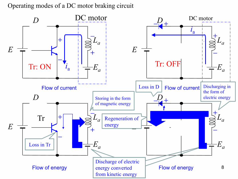
Flow of current
Flow of energy
Flow of current
Flow of energy
+
- +
-
+
-
+
-
+
-
+ -
+
-
+ -
8
Loss in Tr
Discharging in the form of electric energy Storing in the form
of magnetic energy
Loss in D
Discharge of electric energy converted from kinetic energy
Operating modes of a DC motor braking circuit
Regeneration of energy
Tr
Tr: OFF Tr: ON
D1
D2
E
9
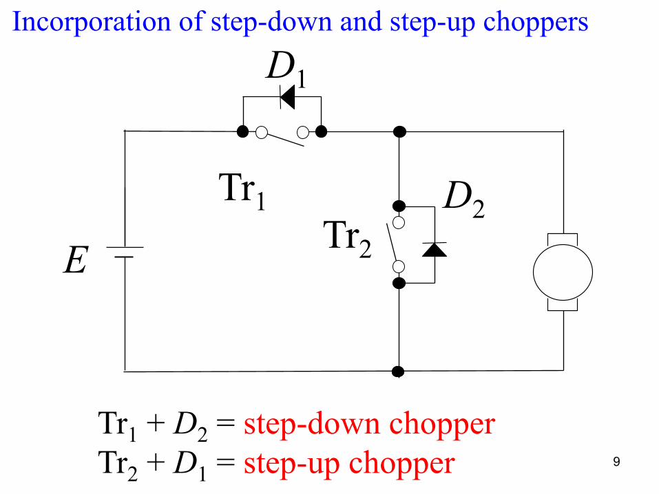
Incorporation of step-down and step-up choppers
Tr1 + D2 = step-down chopper Tr2 + D1 = step-up chopper
Tr1 Tr2
10
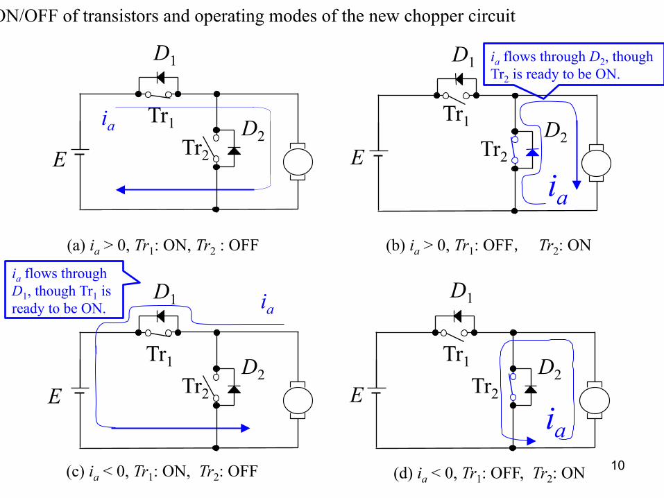
(a) ia > 0, Tr1: ON, Tr2 : OFF (b) ia > 0, Tr1: OFF, Tr2: ON
(c) ia < 0, Tr1: ON, Tr2: OFF (d) ia < 0, Tr1: OFF, Tr2: ON
ia flows through D2, though Tr2 is ready to be ON.
ON/OFF of transistors and operating modes of the new chopper circuit
D1
Tr1 Tr2
D2
ia
D1
Tr1 Tr2
D2 ia
E E
D1
Tr1 Tr2
D2
ia
D1
Tr1 Tr2
D2
ia
E E
ia flows through D1, though Tr1 is ready to be ON.
D1
Tr1 Tr2
D2
E
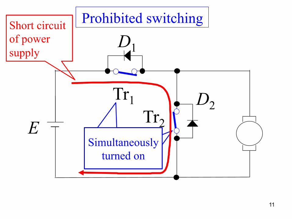
11
Simultaneously turned on
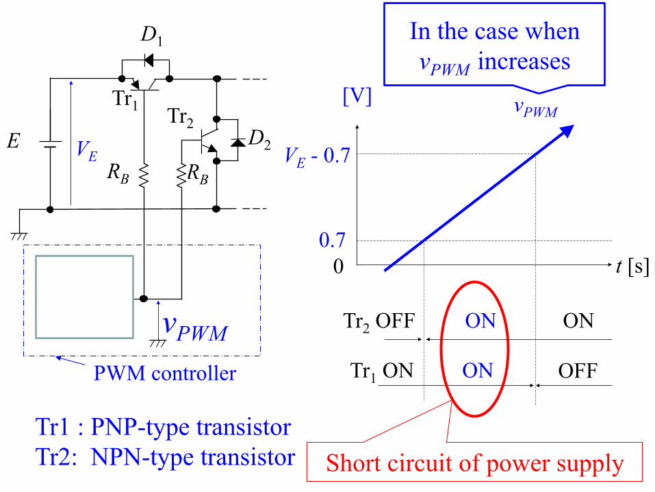
Prohibited switching Short circuit of power supply
D1
Tr1
E
Tr2 D2
RB RB
-
+
VE
vPWM
[V]
0 0.7
VE - 0.7
Tr2 OFF
ON
t [s]
ON
Tr1 ON
Short circuit of power supply
OFF
ON
vPWM
PWM controller
In the case when vPWM increases
Tr1 : PNP-type transistor Tr2: NPN-type transistor
[V]
0
-0.7
0.7 vBE
t [s]
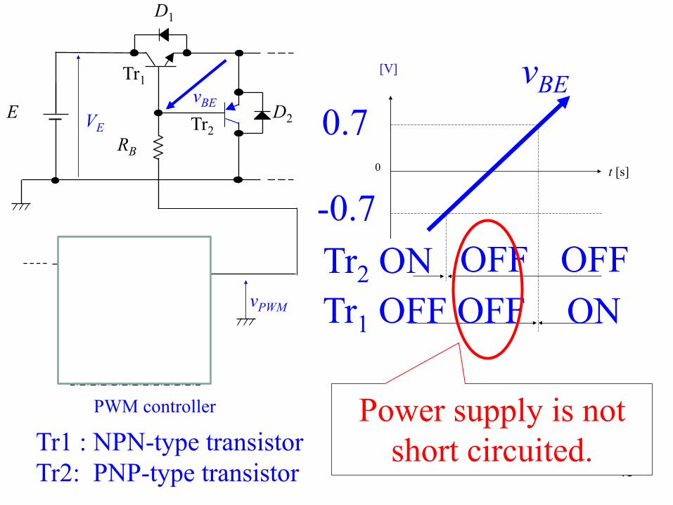
vBE
D1
Tr1
E Tr2 D2
RB
VE
vref
三角波生成回路
- +
vtri
OP
vPWM
Tr2 ON OFF OFF
13
PWM controller
Tr1 : NPN-type transistor Tr2: PNP-type transistor
OFF Tr1 OFF ON
Power supply is not short circuited.
vωcom vω
t [s]
ia [mA]
t [s]
vωt [s]
[V]
(a) with the brake
(b) without the brake
0 1 2 3
0 1 2 3
0 1 2 3
0 1 2 3
[V]
vωcom
1 3
14
ia < 0
The deceleration time is made shorter.
ω
-
+
0.1µF100k
VR2 C1
OP1
D DCM1
DCM2
STEP 8. Circuit construction practice Design the circuit that satisfies the following. P gain Kp and I gain KI of the PI controller are 5 and
1000, respectively. If SW1 is turned on, the motor stops. If SW2 is turned on, a brake can be applied to DCM1. If SW2 is turned off, the brake is not available.
6V
3V
vPWM
510R4
LED1
(A1 A0 = 10)
3V PIC16F615 PIC12F615 PIC12F615
P1B
A2 A1 A0 1µFCS
-vωcom vcom
vω510 RB
Tr1 Tr2
D1
2SC2120 2SA950
10k
10k
R2
R1
2kR6
SW1
SW2
50Rs


![[4063] – 67 - Savitribai Phule Pune · PDF file[4063] – 67 T.E. (E & TC/Electronics, ... A step down DC chopper has a resistive load of R=15Ω and input voltage ... thickness of](https://static.fdocument.org/doc/165x107/5a9dd2c37f8b9abd0a8d9823/4063-67-savitribai-phule-pune-4063-67-te-e-tcelectronics-a.jpg)