Porous Problems in Fluid Mechanics
10
4.52 Water flows steadily past a porous flat plate. Constant suction is applied along the porous section. The velocity profile at section cd is u U N 5 3 y δ hi 2 2 y δ hi 3=2 Evaluate the mass flow rate across section bc. L = 2 m V = –0.2j mm/s ^ d a c u δ = 1.5 mm Width, w = 1.5 m y x U = 3 m/s b P4.52, P4.53 4.53 Consider incompressible steady flow of standard air in a boundary layer on the length of porous surface shown. Assume the boundary layer at the downstream end of the surface has an approximately parabolic velocity profile, u/U N 5 2(y/δ) 2 (y/δ) 2 . Uniform suction is applied along the porous surface, as shown. Calculate the volume flow rate across surface cd, through the porous suction surface, and across surface bc. 4.54 A tank of fixed volume contains brine with initial density, ρ i , greater than water. Pure water enters the tank steadily and mixes thoroughly with the brine in the tank. The liquid level in the tank remains constant. Derive expressions for (a) the rate of change of density of the liquid mixture in the tank and (b) the time required for the density to reach the value ρ f , where ρ i . ρ f . ρ H 2 O . m in • ρ m out • ρ H 2 O V = constant P4.54 4.55 A conical funnel of half-angle θ 5 30 drains through a small hole of diameter d 5 0.25 in. at the vertex. The speed of the liquid leaving the funnel is approximately V ¼ ffiffiffiffiffiffiffi 2gy p , where y is the height of the liquid free surface above the hole. The funnel initially is filled to height y 0 5 12 in. Obtain an expression for the time, t, for the funnel to completely drain, and evaluate. Find the time to drain from 12 in. to 6 in. (a change in depth of 6 in.), and from 6 in. to completely empty (also a change in depth of 6 in.). Can you explain the discrepancy in these times? Plot the drain time t as a function diameter d for d ranging from 0.25 in. to 0.5 in. 4.56 For the funnel of Problem 4.55, find the diameter d required if the funnel is to drain in t 5 1 min. from an initial depth y 0 5 12 in. Plot the diameter d required to drain the funnel in 1 min as a function of initial depth y 0 , for y 0 ranging from 1 in. to 24 in. 4.57 Over time, air seeps through pores in the rubber of high- pressure bicycle tires. The saying is that a tire loses pressure at the rate of “a pound [1 psi] a day.” The true rate of pressure loss is not constant; instead, the instantaneous leakage mass flow rate is proportional to the air density in the tire and to the gage pressure in the tire, _ m~ρp. Because the leakage rate is slow, air in the tire is nearly isothermal. Consider a tire that initially is inflated to 0.6 MPa (gage). Assume the initial rate of pressure loss is 1 psi per day. Estimate how long it will take for the pressure to drop to 500 kPa. How accurate is “a pound a day” over the entire 30 day period? Plot the pressure as a function of time over the 30 day period. Show the rule-of- thumb results for comparison. Momentum Equation for Inertial Control Volume 4.58 Evaluate the net rate of flux of momentum out through the control surface of Problem 4.24. 4.59 For the conditions of Problem 4.34, evaluate the ratio of the x-direction momentum flux at the channel outlet to that at the inlet. 4.60 For the conditions of Problem 4.35, evaluate the ratio of the x-direction momentum flux at the pipe outlet to that at the inlet. 4.61 Evaluate the net momentum flux through the bend of Problem 4.38, if the depth normal to the diagram is w 5 1 m. 4.62 Evaluate the net momentum flux through the channel of Problem 4.39. Would you expect the outlet pressure to be higher, lower, or the same as the inlet pressure? Why? 4.63 Water jets are being used more and more for metal cutting operations. If a pump generates a flow of 1 gpm through an orifice of 0.01 in. diameter, what is the average jet speed? What force (lbf) will the jet produce at impact, assuming as an approximation that the water sprays sideways after impact? 4.64 Considering that in the fully developed region of a pipe, the integral of the axial momentum is the same at all cross sections, explain the reason for the pressure drop along the pipe. 4.65 Find the force required to hold the plug in place at the exit of the water pipe. The flow rate is 1.5 m 3 /s, and the upstream pressure is 3.5 MPa. F 0.2 m 0.25 m P4.65 4.66 A jet of water issuing from a stationary nozzle at 10 m/s (A j 5 0.1 m 2 ) strikes a turning vane mounted on a cart as shown. The vane turns the jet through angle θ 5 40 . Determine the value of M required to hold the cart sta- tionary. If the vane angle θ is adjustable, plot the mass, M, needed to hold the cart stationary versus θ for 0 # θ # 180 . 154 Chapter 4 Basic Equations in Integral Form for a Control Volume
-
Upload
jengwonwoo -
Category
Documents
-
view
2.192 -
download
29
description
Some Problems for Porous Examples in Fluid Mechanics
Transcript of Porous Problems in Fluid Mechanics
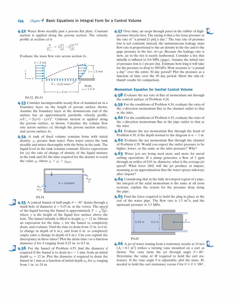
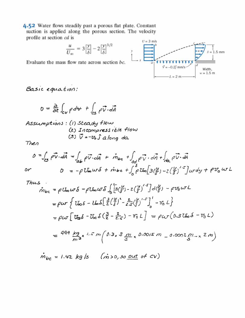
4.52 Water flows steadily past a porous flat plate. Constantsuction is applied along the porous section. The velocityprofile at section cd is
u
UN5 3
y
δ
h i2 2
y
δ
h i3=2
Evaluate the mass flow rate across section bc.
L = 2 m
V = –0.2j mm/s^ da
c
u δ = 1.5 mm
Width,w = 1.5 m
y
x
U = 3 m/sb
P4.52, P4.53
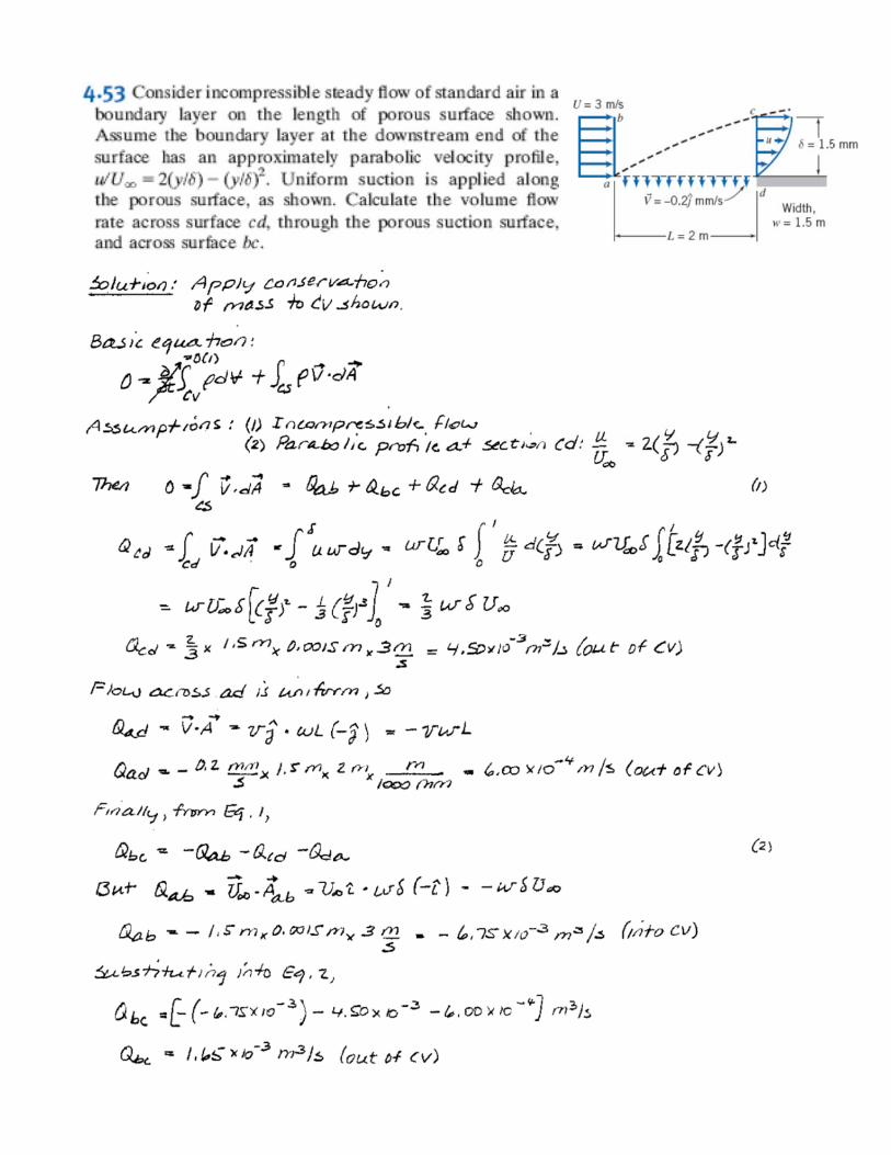
4.53 Consider incompressible steady flow of standard air in aboundary layer on the length of porous surface shown.Assume the boundary layer at the downstream end of thesurface has an approximately parabolic velocity profile,u/UN5 2(y/δ)2 (y/δ)2. Uniform suction is applied alongthe porous surface, as shown. Calculate the volume flowrate across surface cd, through the porous suction surface,and across surface bc.
4.54 A tank of fixed volume contains brine with initialdensity, ρi, greater than water. Pure water enters the tanksteadily and mixes thoroughly with the brine in the tank. Theliquid level in the tank remains constant. Derive expressionsfor (a) the rate of change of density of the liquid mixturein the tank and (b) the time required for the density to reachthe value ρf, where ρi . ρf . ρH2O
.
min•
ρ
mout•
ρ
H2O
V = constant
P4.54
4.55 A conical funnel of half-angle θ 5 30� drains through asmall hole of diameter d 5 0.25 in. at the vertex. The speedof the liquid leaving the funnel is approximately V ¼ ffiffiffiffiffiffiffiffi
2gyp
,where y is the height of the liquid free surface above thehole. The funnel initially is filled to height y0 5 12 in. Obtainan expression for the time, t, for the funnel to completelydrain, and evaluate. Find the time to drain from 12 in. to 6 in.(a change in depth of 6 in.), and from 6 in. to completelyempty (also a change in depth of 6 in.). Can you explain thediscrepancy in these times? Plot the drain time t as a functiondiameter d for d ranging from 0.25 in. to 0.5 in.
4.56 For the funnel of Problem 4.55, find the diameter drequired if the funnel is to drain in t 5 1 min. from an initialdepth y0 5 12 in. Plot the diameter d required to drain thefunnel in 1 min as a function of initial depth y0, for y0 rangingfrom 1 in. to 24 in.
4.57 Over time, air seeps through pores in the rubber of high-pressure bicycle tires. The saying is that a tire loses pressure atthe rate of “a pound [1 psi] a day.” The true rate of pressureloss is not constant; instead, the instantaneous leakage massflow rate is proportional to the air density in the tire and to thegage pressure in the tire, _m~ρp. Because the leakage rate isslow, air in the tire is nearly isothermal. Consider a tire thatinitially is inflated to 0.6 MPa (gage). Assume the initial rateof pressure loss is 1 psi per day. Estimate how long it will takefor the pressure to drop to 500 kPa. How accurate is “a pounda day” over the entire 30 day period? Plot the pressure as afunction of time over the 30 day period. Show the rule-of-thumb results for comparison.
Momentum Equation for Inertial Control Volume
4.58 Evaluate the net rate of flux of momentum out throughthe control surface of Problem 4.24.
4.59 For the conditions of Problem 4.34, evaluate the ratio ofthe x-direction momentum flux at the channel outlet to thatat the inlet.
4.60 For the conditions of Problem 4.35, evaluate the ratio ofthe x-direction momentum flux at the pipe outlet to that atthe inlet.
4.61 Evaluate the net momentum flux through the bend ofProblem 4.38, if the depth normal to the diagram is w 5 1 m.
4.62 Evaluate the net momentum flux through the channelof Problem 4.39. Would you expect the outlet pressure to behigher, lower, or the same as the inlet pressure? Why?
4.63 Water jets are being used more and more for metalcutting operations. If a pump generates a flow of 1 gpmthrough an orifice of 0.01 in. diameter, what is the average jetspeed? What force (lbf) will the jet produce at impact,assuming as an approximation that the water sprays sidewaysafter impact?
4.64 Considering that in the fully developed region of a pipe,the integral of the axial momentum is the same at all crosssections, explain the reason for the pressure drop alongthe pipe.
4.65 Find the force required to hold the plug in place at theexit of the water pipe. The flow rate is 1.5 m3/s, and theupstream pressure is 3.5 MPa.
F0.2 m0.25 m
P4.65
4.66 A jet of water issuing from a stationary nozzle at 10 m/s(Aj5 0.1 m2) strikes a turning vane mounted on a cart asshown. The vane turns the jet through angle θ5 40�.Determine the value of M required to hold the cart sta-tionary. If the vane angle θ is adjustable, plot the mass, M,needed to hold the cart stationary versus θ for 0 # θ # 180�.
154 Chapter 4 Basic Equations in Integral Form for a Control Volume
Stagnationtube
Fixed vane
Freewater jet
Open
Hg 0.75 m
Water
30°
50 mm dia.
P4.116
*4.117 A Venturi meter installed along a water pipe consistsof a convergent section, a constant-area throat, and adivergent section. The pipe diameter isD 5 100 mm, and thethroat diameter is d 5 50 mm. Find the net fluid force actingon the convergent section if the water pressure in the pipe is200 kPa (gage) and the flow rate is 1000 L/min. For thisanalysis, neglect viscous effects.
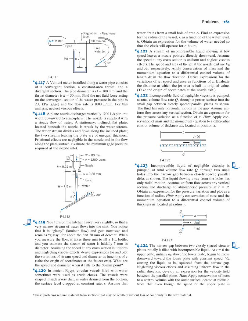
*4.118 A plane nozzle discharges vertically 1200 L/s per unitwidth downward to atmosphere. The nozzle is supplied witha steady flow of water. A stationary, inclined, flat plate,located beneath the nozzle, is struck by the water stream.The water stream divides and flows along the inclined plate;the two streams leaving the plate are of unequal thickness.Frictional effects are negligible in the nozzle and in the flowalong the plate surface. Evaluate the minimum gage pressurerequired at the nozzle inlet.
h = 0.25 m
H = 7.5 m
V3
θ θ
Water
w = 0.25 mm
Nozzle
Q = 1200 L/s/m
V2= 20
W = 80 mm
V
V
= 30°
P4.118
*4.119 You turn on the kitchen faucet very slightly, so that avery narrow stream of water flows into the sink. You noticethat it is “glassy” (laminar flow) and gets narrower andremains “glassy” for about the first 50 mm of descent. Whenyou measure the flow, it takes three min to fill a 1-L bottle,and you estimate the stream of water is initially 5 mm indiameter. Assuming the speed at any cross section is uniformand neglecting viscous effects, derive expressions for and plotthe variations of stream speed and diameter as functions of z(take the origin of coordinates at the faucet exit). What arethe speed and diameter when it falls to the 50-mm point?
*4.120 In ancient Egypt, circular vessels filled with watersometimes were used as crude clocks. The vessels wereshaped in such a way that, as water drained from the bottom,the surface level dropped at constant rate, s. Assume that
water drains from a small hole of area A. Find an expressionfor the radius of the vessel, r, as a function of the water level,h. Obtain an expression for the volume of water needed sothat the clock will operate for n hours.
*4.121 A stream of incompressible liquid moving at lowspeed leaves a nozzle pointed directly downward. Assumethe speed at any cross section is uniform and neglect viscouseffects. The speed and area of the jet at the nozzle exit are V0
and A0, respectively. Apply conservation of mass and themomentum equation to a differential control volume oflength dz in the flow direction. Derive expressions for thevariations of jet speed and area as functions of z. Evaluatethe distance at which the jet area is half its original value.(Take the origin of coordinates at the nozzle exit.)
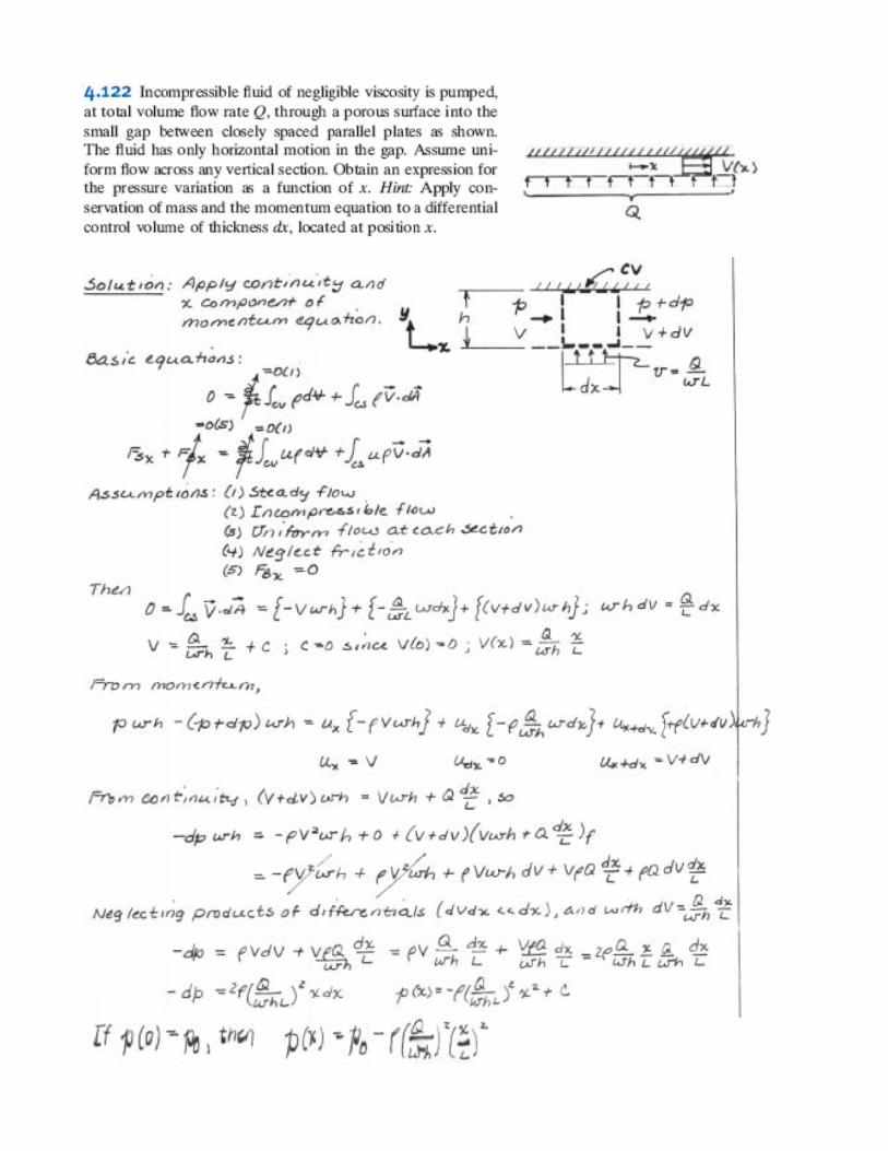
*4.122 Incompressible fluid of negligible viscosity is pumped,at total volume flow rate Q, through a porous surface into thesmall gap between closely spaced parallel plates as shown.The fluid has only horizontal motion in the gap. Assume uni-form flow across any vertical section. Obtain an expression forthe pressure variation as a function of x. Hint: Apply con-servation of mass and the momentum equation to a differentialcontrol volume of thickness dx, located at position x.
L
V (x)
x
Q
P4.122
*4.123 Incompressible liquid of negligible viscosity ispumped, at total volume flow rate Q, through two smallholes into the narrow gap between closely spaced paralleldisks as shown. The liquid flowing away from the holes hasonly radial motion. Assume uniform flow across any verticalsection and discharge to atmospheric pressure at r 5 R.Obtain an expression for the pressure variation and plot as afunction of radius. Hint: Apply conservation of mass and themomentum equation to a differential control volume ofthickness dr located at radius r.
r
Q__2
Q__2
V(r)
R
P4.123
*4.124 The narrow gap between two closely spaced circularplates initially is filled with incompressible liquid. At t 5 0 theupper plate, initially h0 above the lower plate, begins to movedownward toward the lower plate with constant speed, V0,causing the liquid to be squeezed from the narrow gap.Neglecting viscous effects and assuming uniform flow in theradial direction, develop an expression for the velocity fieldbetween the parallel plates. Hint: Apply conservation of massto a control volume with the outer surface located at radius r.Note that even though the speed of the upper plate is
*These problems require material from sections that may be omitted without loss of continuity in the text material.
Problems 161
A5 2 m24 � s21 and x is measured in meters. Find the sim-plest y component of velocity for this flow field. Evaluate theacceleration of a fluid particle at point (x, y)5 (1, 3).
5.42 The velocity field within a laminar boundary layer isapproximated by the expression
~V 5AUy
x1=2i1
AUy2
4x3=2j
In this expression, A5 141 m21/2, and U5 0.240 m/s is thefreestream velocity. Show that this velocity field represents apossible incompressible flow. Calculate the acceleration of afluid particle at point (x, y)5 (0.5 m, 5 mm). Determine theslope of the streamline through the point.
5.43 Wave flow of an incompressible fluid into a solid surfacefollows a sinusoidal pattern. Flow is two-dimensional withthe x axis normal to the surface and y axis along the wall. Thex component of the flow follows the pattern
u 5 Ax sin2πtT
� �
Determine the y component of flow (v) and the convectiveand local components of the acceleration vector.
5.44 The y component of velocity in a two-dimensional,incompressible flow field is given by v52Axy, where v is inm/s, x and y are in meters, and A is a dimensional constant.There is no velocity component or variation in the z direc-tion. Determine the dimensions of the constant, A. Find thesimplest x component of velocity in this flow field. Calculatethe acceleration of a fluid particle at point (x, y)5 (1, 2).
5.45 Consider the velocity field ~V 5 Ax=ðx2 1 y2Þi1Ay=ðx2 1 y2Þj in the xy plane, where A5 10 m2/s, and x and y aremeasured inmeters. Is this an incompressible flowfield?Derivean expression for the fluid acceleration. Evaluate the velocityand acceleration along the x axis, the y axis, and along a linedefined by y5 x. What can you conclude about this flow field?
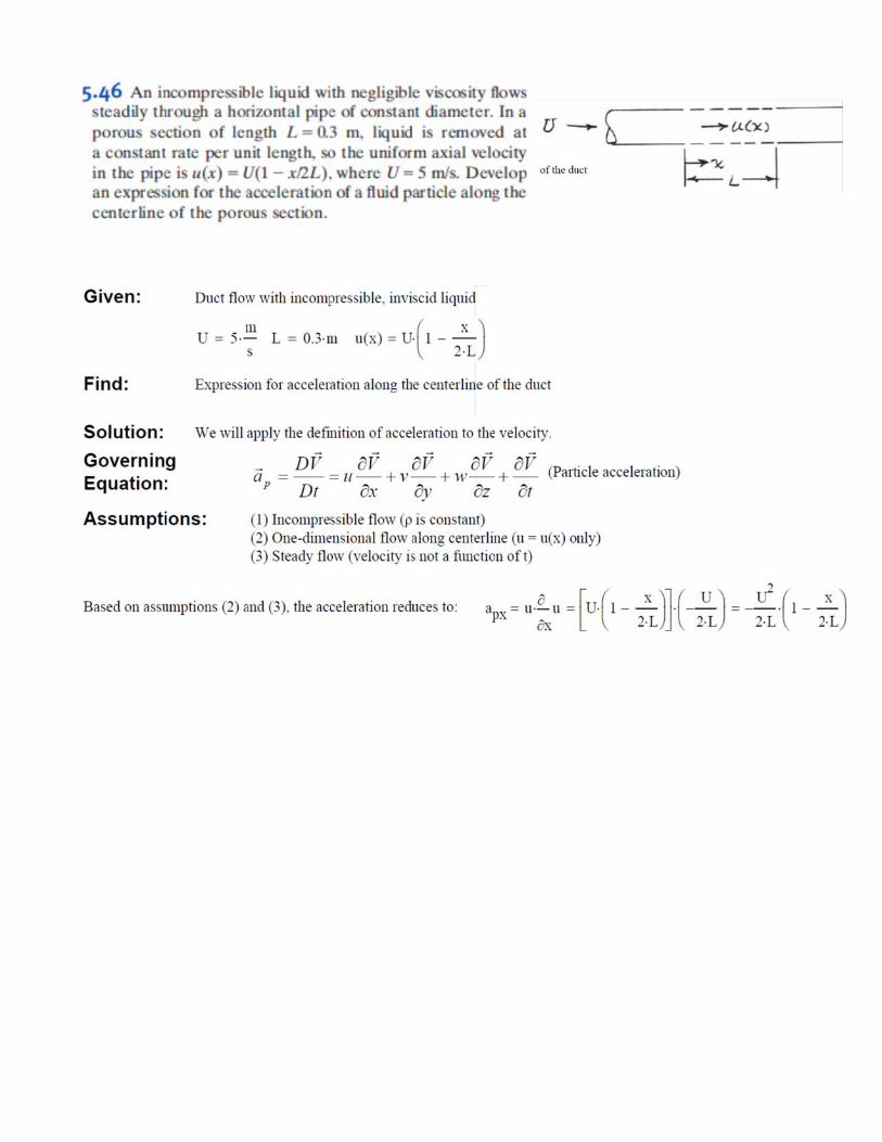
5.46 An incompressible liquid with negligible viscosity flowssteadily through a horizontal pipe of constant diameter. In aporous section of length L5 0.3 m, liquid is removed ata constant rate per unit length, so the uniform axial velocityin the pipe is u(x)5U(12 x/2L), where U5 5 m/s. Developan expression for the acceleration of a fluid particle along thecenterline of the porous section.
5.47 An incompressible liquid with negligible viscosity flowssteadily through a horizontal pipe. The pipe diameter linearlyvaries from 4 in. to 1 in. over a length of 6 ft. Develop anexpression for the acceleration of a fluid particle along thepipe centerline. Plot the centerline velocity and accelerationversus position along the pipe, if the inlet centerline velocityis 3 ft/s.
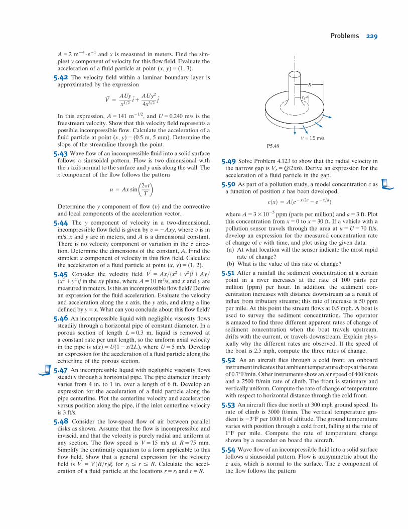
5.48 Consider the low-speed flow of air between paralleldisks as shown. Assume that the flow is incompressible andinviscid, and that the velocity is purely radial and uniform atany section. The flow speed is V5 15 m/s at R5 75 mm.Simplify the continuity equation to a form applicable to thisflow field. Show that a general expression for the velocityfield is ~V 5 VðR=rÞer for ri # r # R. Calculate the accel-eration of a fluid particle at the locations r5 ri and r5R.
5.49 Solve Problem 4.123 to show that the radial velocity inthe narrow gap is Vr5Q/2πrh. Derive an expression for theacceleration of a fluid particle in the gap.
5.50 As part of a pollution study, a model concentration c asa function of position x has been developed,
cðxÞ 5 Aðe2 x=2a 2 e2 x=aÞwhere A5 33 1025 ppm (parts per million) and a5 3 ft. Plotthis concentration from x5 0 to x5 30 ft. If a vehicle with apollution sensor travels through the area at u5U5 70 ft/s,develop an expression for the measured concentration rateof change of c with time, and plot using the given data.(a) At what location will the sensor indicate the most rapid
rate of change?(b) What is the value of this rate of change?
5.51 After a rainfall the sediment concentration at a certainpoint in a river increases at the rate of 100 parts permillion (ppm) per hour. In addition, the sediment con-centration increases with distance downstream as a result ofinflux from tributary streams; this rate of increase is 50 ppmper mile. At this point the stream flows at 0.5 mph. A boat isused to survey the sediment concentration. The operatoris amazed to find three different apparent rates of change ofsediment concentration when the boat travels upstream,drifts with the current, or travels downstream. Explain phys-ically why the different rates are observed. If the speed ofthe boat is 2.5 mph, compute the three rates of change.
5.52 As an aircraft flies through a cold front, an onboardinstrument indicates that ambient temperaturedrops at the rateof 0.7�F/min. Other instruments show an air speed of 400 knotsand a 2500 ft/min rate of climb. The front is stationary andvertically uniform. Compute the rate of change of temperaturewith respect to horizontal distance through the cold front.
5.53 An aircraft flies due north at 300 mph ground speed. Itsrate of climb is 3000 ft/min. The vertical temperature gra-dient is23�F per 1000 ft of altitude. The ground temperaturevaries with position through a cold front, falling at the rate of1�F per mile. Compute the rate of temperature changeshown by a recorder on board the aircraft.
5.54 Wave flow of an incompressible fluid into a solid surfacefollows a sinusoidal pattern. Flow is axisymmetric about thez axis, which is normal to the surface. The z component ofthe flow follows the pattern
R
ri
V = 15 m/s
P5.48
Problems 229
Vz 5 Az sin2πtT
� �
Determine (a) the radial component of flow (Vr) and (b) theconvective and local components of the acceleration vector.
5.55 Expand ð~V �rÞ~V in rectangular coordinates by directsubstitution of the velocity vector to obtain the convectiveacceleration of a fluid particle. Verify the results given inEqs. 5.11.
5.56 A steady, two-dimensional velocity field is given by~V 5 Axi2Ayj; whereA 5 1 s21: Show that the streamlinesfor this flow are rectangular hyperbolas, xy5C. Obtain ageneral expression for the acceleration of a fluid particle inthis velocity field. Calculate the acceleration of fluid particlesat the points ðx; yÞ 5 ð12 ; 2Þ; ð1; 1Þ; and ð2; 1
2Þ; where x andy are measured in meters. Plot streamlines that correspondto C5 0, 1, and 2 m2 and show the acceleration vectors onthe streamline plot.
5.57 A velocity field is represented by the expression ~V 5
ðAx2BÞi2Ayj; where A5 0.2 s21, B5 0.6 m � s21, and thecoordinates are expressed in meters. Obtain a generalexpression for the acceleration of a fluid particle in this velocityfield. Calculate the acceleration of fluid particles at pointsðx; yÞ 5 ð0; 4
3Þ; ð1; 2Þ; and (2, 4). Plot a few streamlines in thexy plane. Show the acceleration vectors on the streamline plot.
5.58 A velocity field is represented by the expression ~V 5ðAx2BÞi1Cyj1Dtk; where A5 2 s21, B5 4 m � s21, D5
5 m � s22, and the coordinates are measured in meters. Deter-mine the proper value for C if the flow field is to be incom-pressible. Calculate the acceleration of a fluid particle located atpoint (x, y)5 (3, 2). Plot a few flow streamlines in the xy plane.
5.59 A linear approximate velocity profile was used in Prob-lem 5.10 to model a laminar incompressible boundary layeron a flat plate. For this profile, obtain expressions for the xand y components of acceleration of a fluid particle in theboundary layer. Locate the maximum magnitudes of the xand y accelerations. Compute the ratio of the maximum xmagnitude to the maximum y magnitude for the flow con-ditions of Problem 5.10.
5.60 A parabolic approximate velocity profile was used inProblem 5.11 to model flow in a laminar incompressibleboundary layer on a flat plate. For this profile, find the x com-ponentofacceleration,ax, of afluidparticlewithin theboundarylayer. Plot ax at location x5 0.8m, where δ5 1.2mm, for a flowwithU5 6m/s. Find themaximum value of ax at this x location.
5.61 Show that the velocity field of Problem 2.18 represents apossible incompressible flow field. Determine and plot thestreamline passing through point (x, y)5 (2, 4) at t5 1.5 s.For the particle at the same point and time, show on the plotthe velocity vector and the vectors representing the local,convective, and total accelerations.
5.62 A sinusoidal approximate velocity profile was used inProblem 5.12 to model flow in a laminar incompressibleboundary layer on a flat plate. For this profile, obtain anexpression for the x and y components of acceleration of afluid particle in the boundary layer. Plot ax and ay at locationx5 3 ft, where δ5 0.04 in., for a flow with U5 20 ft/s. Findthe maxima of ax and ay at this x location.
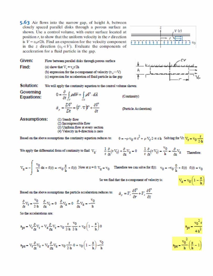
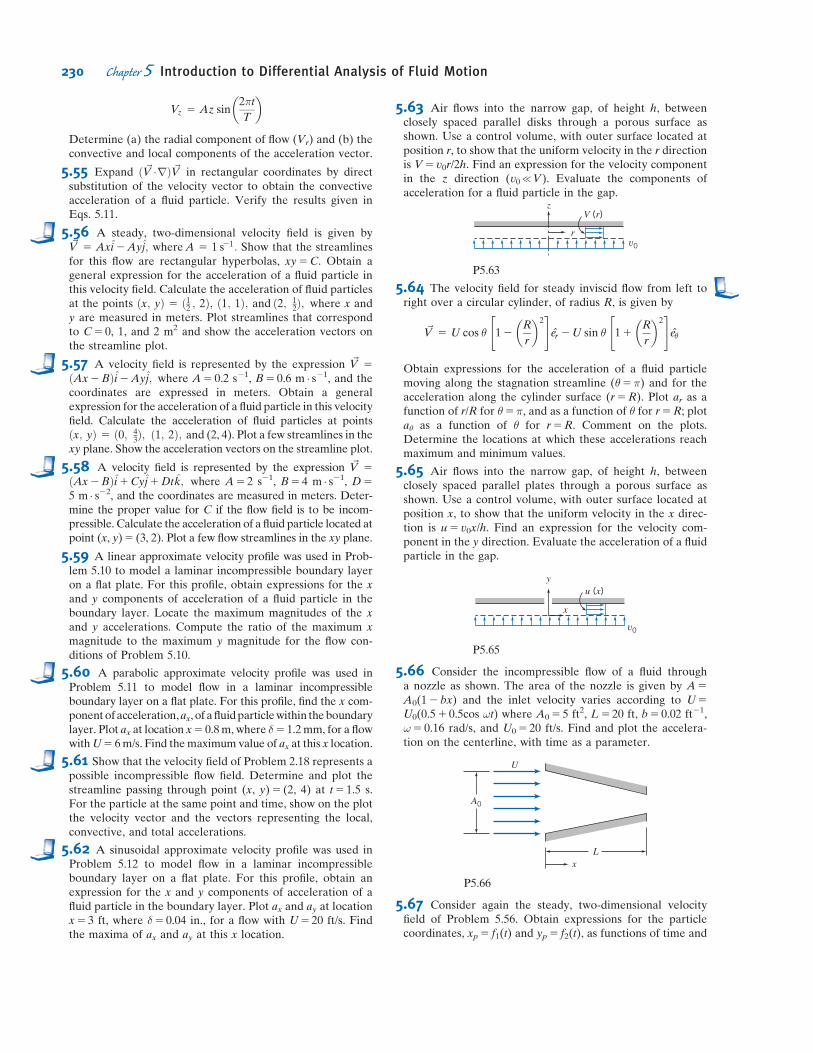
5.63 Air flows into the narrow gap, of height h, betweenclosely spaced parallel disks through a porous surface asshown. Use a control volume, with outer surface located atposition r, to show that the uniform velocity in the r directionis V5 v0r/2h. Find an expression for the velocity componentin the z direction (v0{V). Evaluate the components ofacceleration for a fluid particle in the gap.
v0
zV (r)
r
P5.63
5.64 The velocity field for steady inviscid flow from left toright over a circular cylinder, of radius R, is given by
~V 5 U cos θ 12R
r
� �2" #
er 2U sin θ 11R
r
� �2" #
eθ
Obtain expressions for the acceleration of a fluid particlemoving along the stagnation streamline (θ5π) and for theacceleration along the cylinder surface (r5R). Plot ar as afunction of r/R for θ5π, and as a function of θ for r5R; plotaθ as a function of θ for r5R. Comment on the plots.Determine the locations at which these accelerations reachmaximum and minimum values.
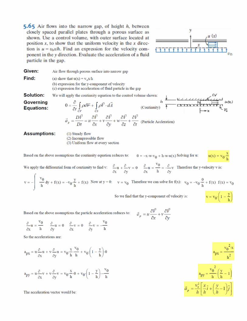
5.65 Air flows into the narrow gap, of height h, betweenclosely spaced parallel plates through a porous surface asshown. Use a control volume, with outer surface located atposition x, to show that the uniform velocity in the x direc-tion is u5 v0x/h. Find an expression for the velocity com-ponent in the y direction. Evaluate the acceleration of a fluidparticle in the gap.
v0
yu (x)
x
P5.65
5.66 Consider the incompressible flow of a fluid througha nozzle as shown. The area of the nozzle is given by A5
A0(12 bx) and the inlet velocity varies according to U5U0(0.51 0.5cos ωt) where A05 5 ft2, L5 20 ft, b5 0.02 ft21,ω5 0.16 rad/s, and U05 20 ft/s. Find and plot the accelera-tion on the centerline, with time as a parameter.
xL
U
A0
P5.66
5.67 Consider again the steady, two-dimensional velocityfield of Problem 5.56. Obtain expressions for the particlecoordinates, xp5 f1(t) and yp5 f2(t), as functions of time and
230 Chapter 5 Introduction to Differential Analysis of Fluid Motion