Plasmas radiofréquence à couplage capacitive: effet de la ...
72
Laboratoire de Physique des Plasmas Plasmas radiofréquence à couplage capacitive: effet de la fréquence, les mélanges de fréquences et la forme d'onde Jean-Paul Booth
Transcript of Plasmas radiofréquence à couplage capacitive: effet de la ...
Laboratoire de Physique des Plasmas
Plasmas radiofréquence à couplage capacitive:
effet de la fréquence,
les mélanges de fréquences
et la forme d'onde
Jean-Paul Booth
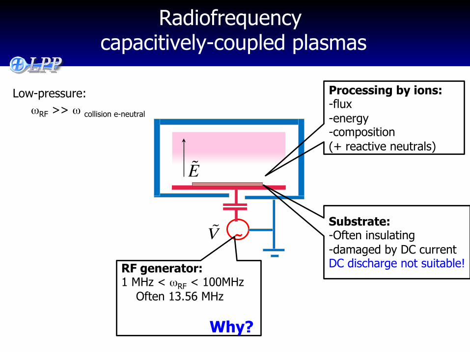
Radiofrequency capacitively-coupled plasmas
~ V
E
Low-pressure: ωRF >> ω collision e-neutral
RF generator: 1 MHz < ωRF < 100MHz Often 13.56 MHz Why?
Substrate: -Often insulating -damaged by DC current DC discharge not suitable!
Processing by ions: -flux -energy -composition (+ reactive neutrals)
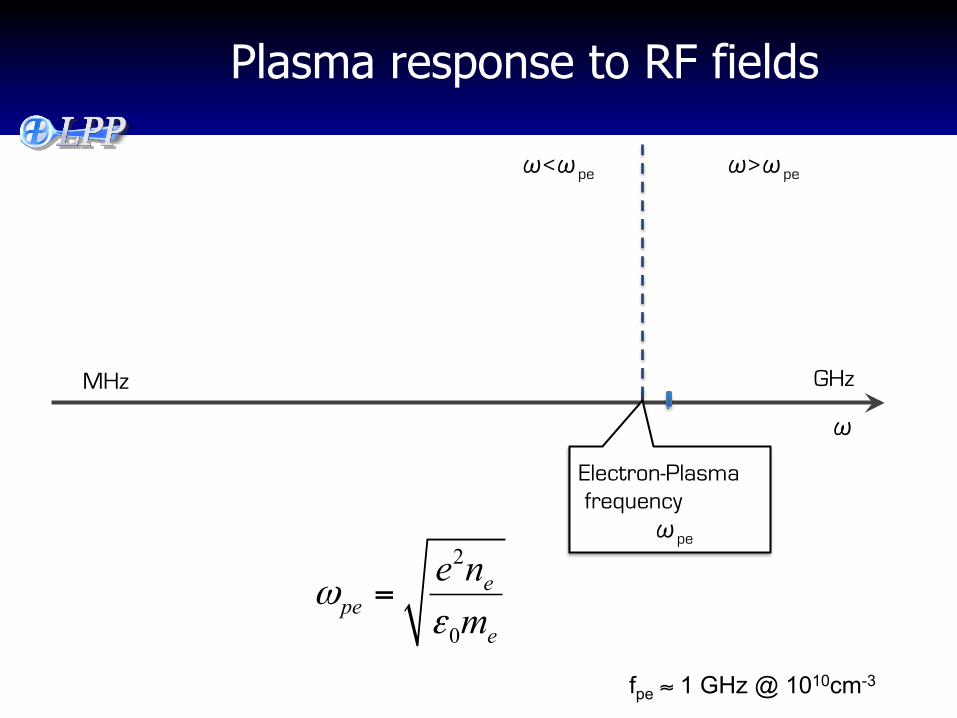
Plasma response to RF fields
MHz GHz
�
�<�pe �>�pe
Electron-Plasma frequency
�pe 2
0
epe
e
e nm
ωε
=
fpe ≈ 1 GHz @ 1010cm-3
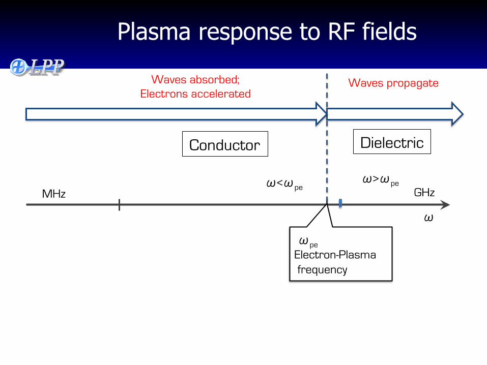
Plasma response to RF fields
MHz GHz
�
Conductor
�<�pe
Dielectric
�>�pe
�pe Electron-Plasma frequency
Waves absorbed; Electrons accelerated
Waves propagate
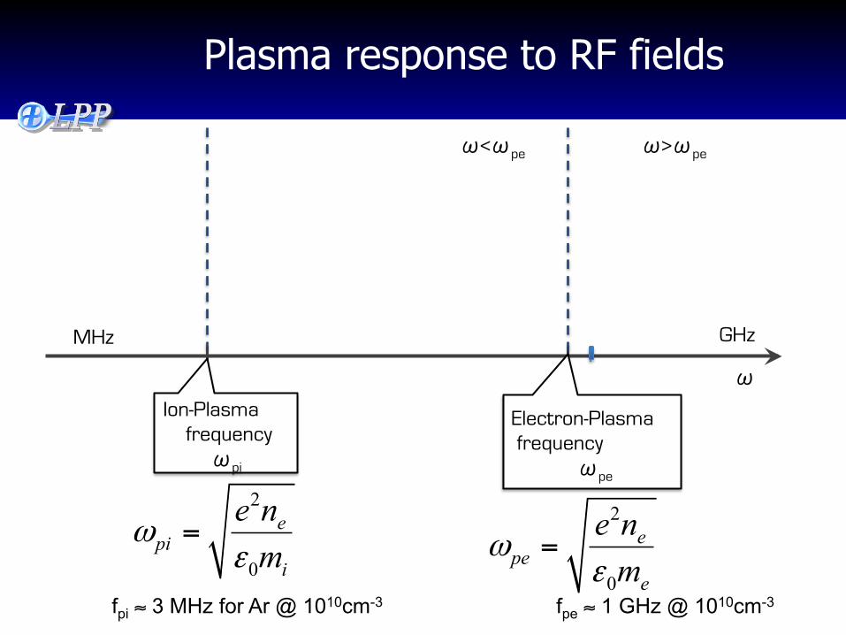
Plasma response to RF fields
MHz GHz
�
�<�pe �>�pe
Electron-Plasma frequency
�pe
Ion-Plasma frequency �pi
2
0
epe
e
e nm
ωε
=
2
0
epi
i
e nm
ωε
=
fpe ≈ 1 GHz @ 1010cm-3 fpi ≈ 3 MHz for Ar @ 1010cm-3
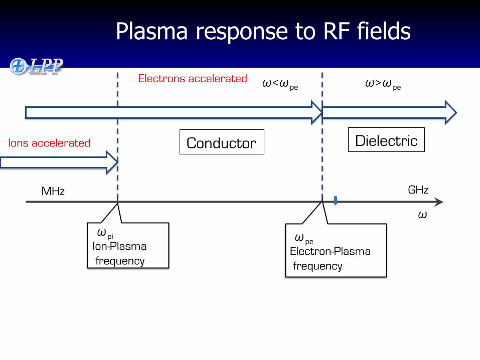
Plasma response to RF fields
MHz GHz
�
Conductor
�<�pe
Dielectric
�>�pe
�pe Electron-Plasma frequency
�pi Ion-Plasma frequency
Electrons accelerated
Ions accelerated
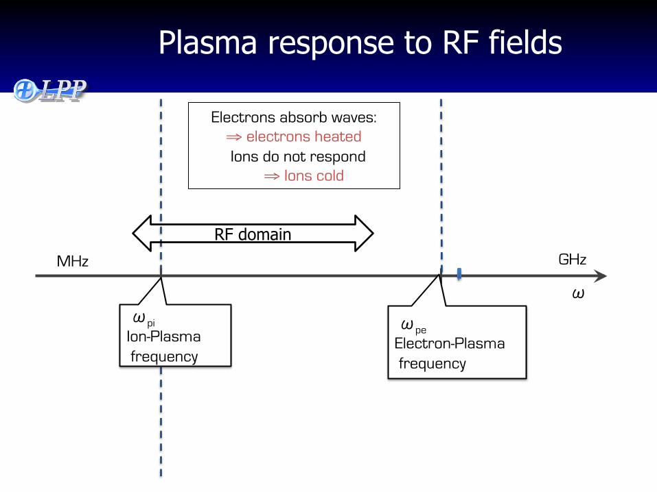
Plasma response to RF fields
MHz GHz
�
Electrons absorb waves: ⇒ electrons heated Ions do not respond
⇒ Ions cold
�pe Electron-Plasma frequency
�pi Ion-Plasma frequency
RF domain
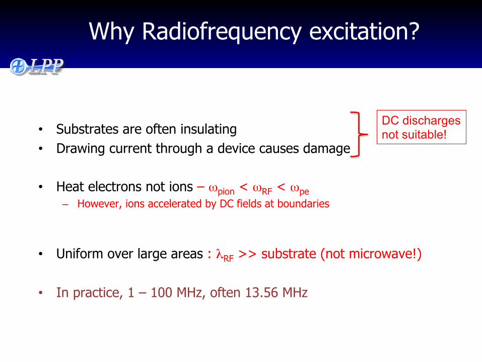
Why Radiofrequency excitation?
• Substrates are often insulating • Drawing current through a device causes damage
• Heat electrons not ions – ωpion < ωRF < ωpe – However, ions accelerated by DC fields at boundaries
• Uniform over large areas : λRF >> substrate (not microwave!)
• In practice, 1 – 100 MHz, often 13.56 MHz
DC discharges not suitable!
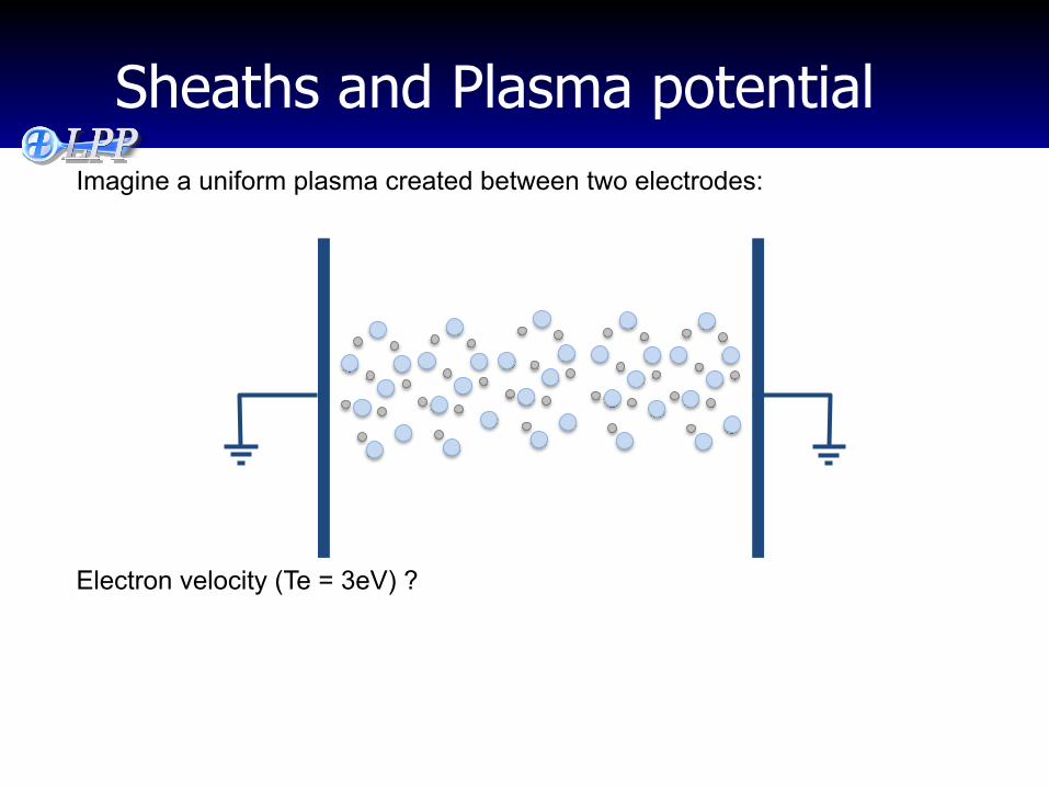
Sheaths and Plasma potential
Electron velocity (Te = 3eV) ?
Imagine a uniform plasma created between two electrodes:
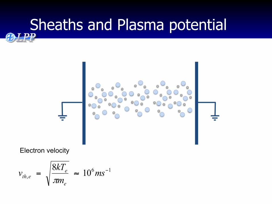
Sheaths and Plasma potential
16, 108 −≈= ms
mkTve
eeth π
Electron velocity
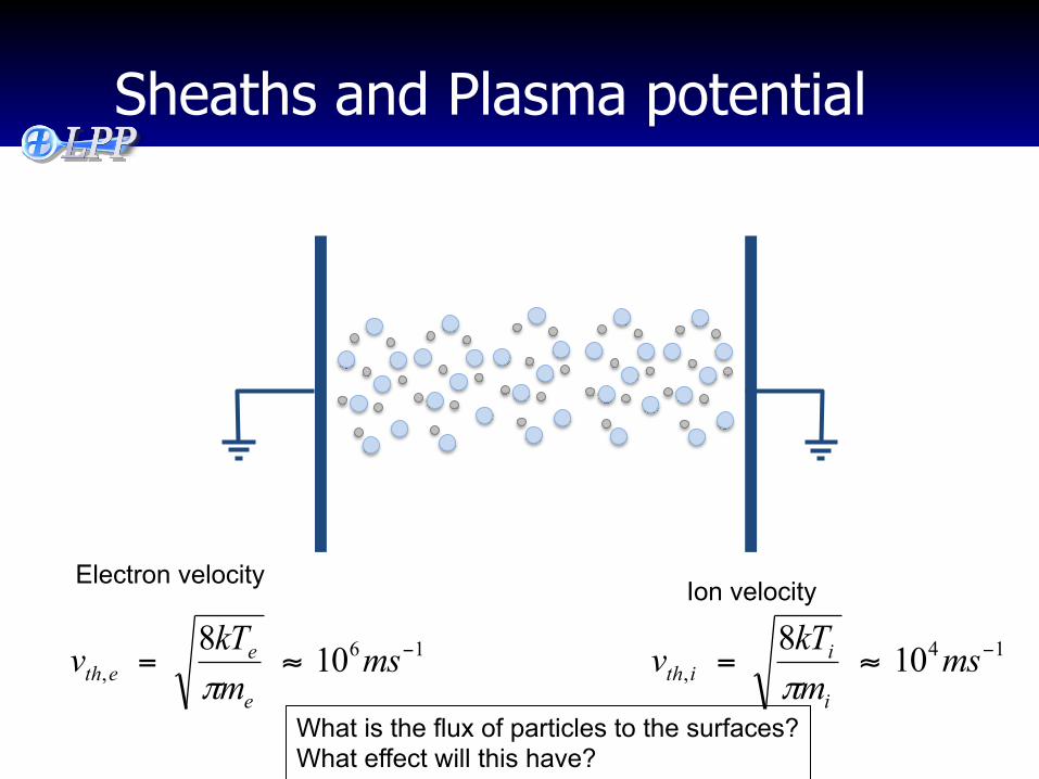
Sheaths and Plasma potential
16, 108 −≈= ms
mkTve
eeth π
14, 108 −≈= ms
mkTvi
iith π
Electron velocity Ion velocity
What is the flux of particles to the surfaces? What effect will this have?
Sheaths and Plasma potential
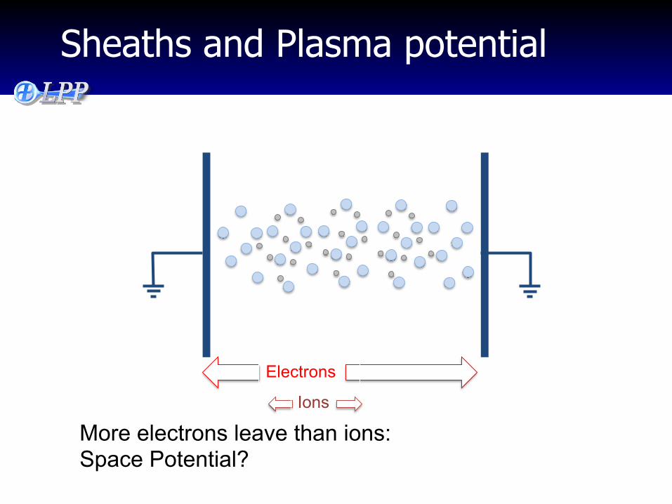
More electrons leave than ions: Space Potential?
Electrons
Ions
Sheaths and Plasma potential
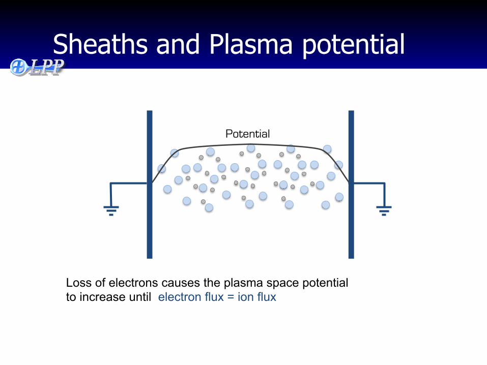
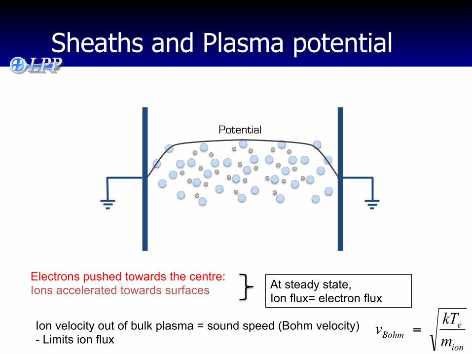
Potential
Loss of electrons causes the plasma space potential to increase until electron flux = ion flux
Sheaths and Plasma potential
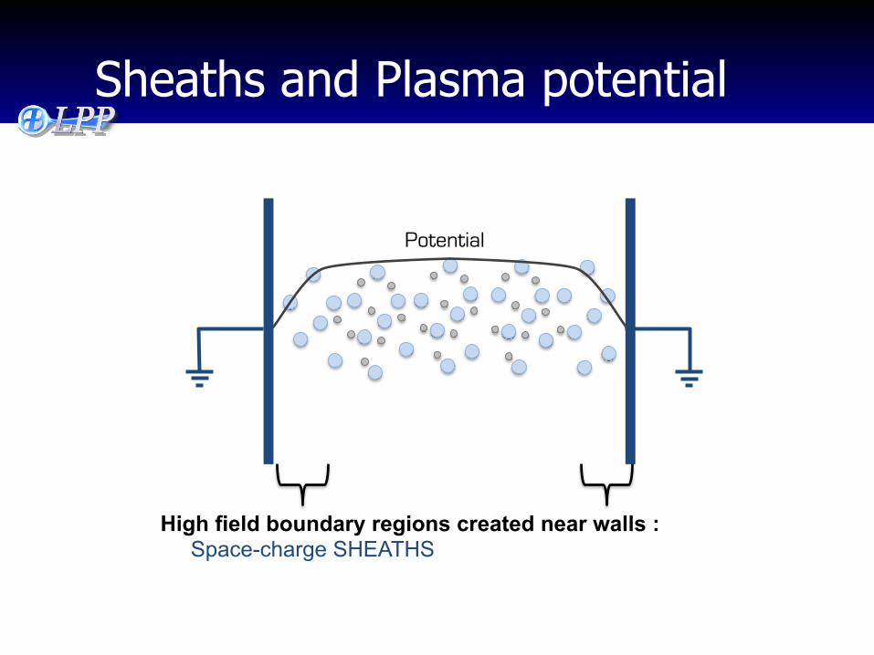
Potential
High field boundary regions created near walls : Space-charge SHEATHS
Sheaths and Plasma potential
Potential
Electrons pushed towards the centre: Ions accelerated towards surfaces At steady state,
Ion flux= electron flux
Ion velocity out of bulk plasma = sound speed (Bohm velocity) - Limits ion flux
ion
eBohm m
kTv =
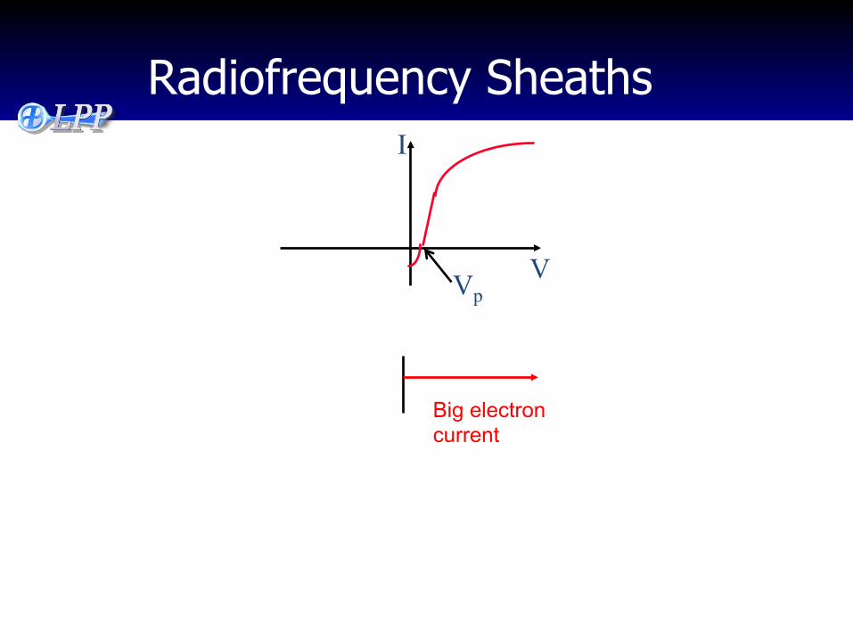
Radiofrequency Sheaths I
V
Big electron current
Vp
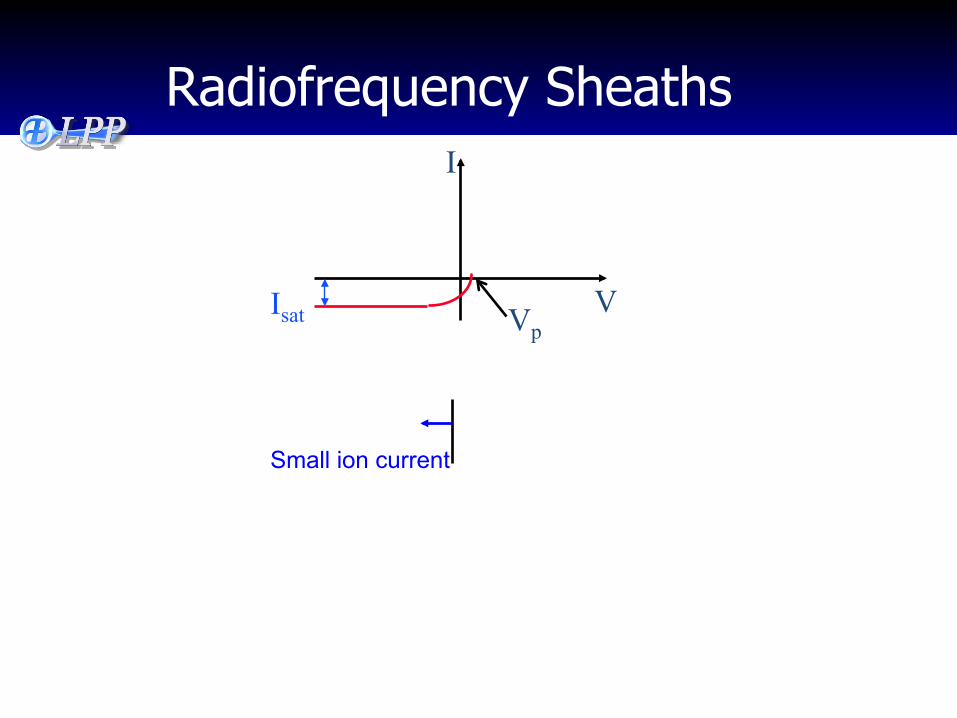
Radiofrequency Sheaths
Isat
I
V
Small ion current
Vp
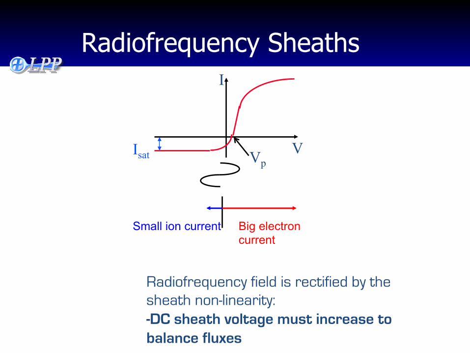
Radiofrequency Sheaths
Radiofrequency field is rectified by the sheath non-linearity: -DC sheath voltage must increase to balance fluxes
Isat
I
V
Big electron current
Small ion current
Vp
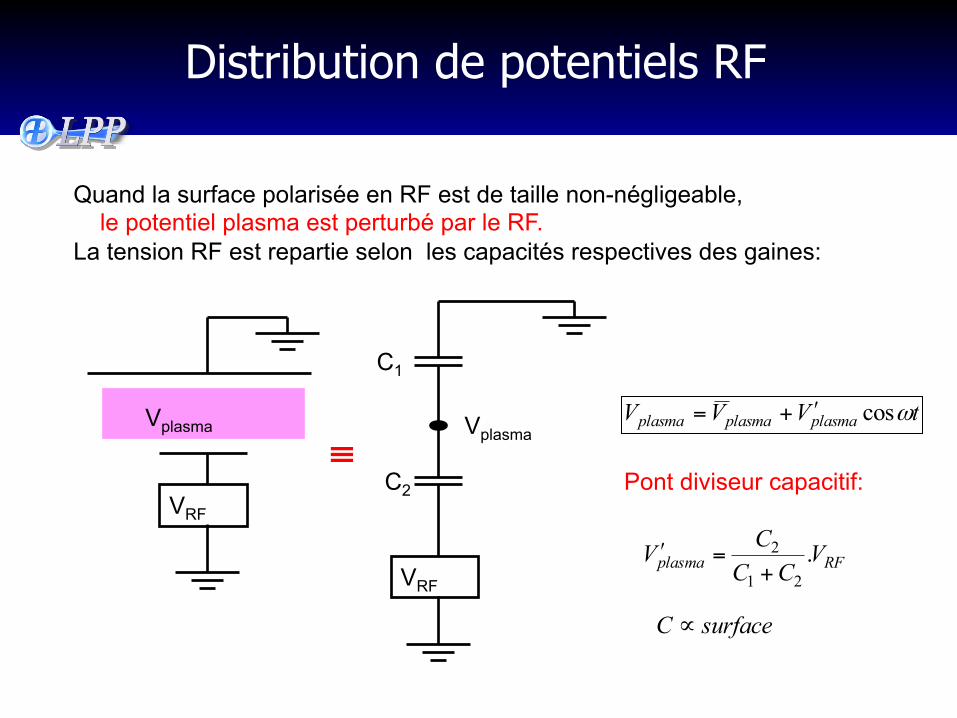
Distribution de potentiels RF
Quand la surface polarisée en RF est de taille non-négligeable, le potentiel plasma est perturbé par le RF. La tension RF est repartie selon les capacités respectives des gaines:
VRF
Vplasma
VRF
C1
C2
Vplasma tVVV plasmaplasmaplasma ωcosʹ+=
Pont diviseur capacitif: ≡
RFplasma VCC
CV .21
2
+=ʹ
surfaceC ∝
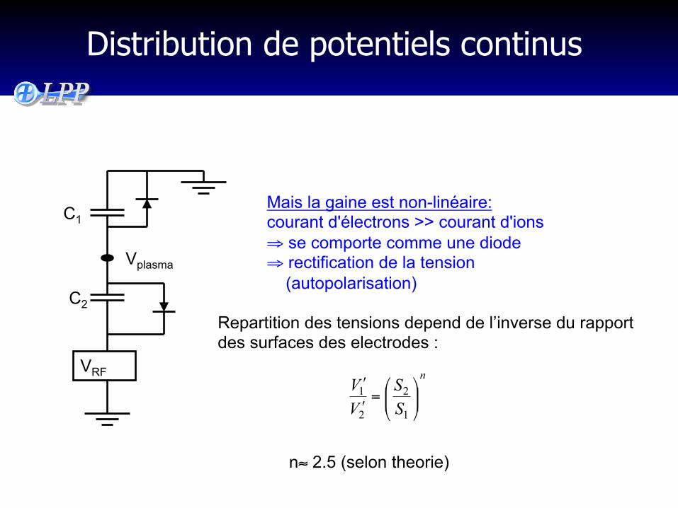
Distribution de potentiels continus
VRF
C1
C2
Vplasma
Mais la gaine est non-linéaire: courant d'électrons >> courant d'ions ⇒ se comporte comme une diode ⇒ rectification de la tension (autopolarisation)
n
SS
VV
⎟⎟⎠
⎞⎜⎜⎝
⎛=ʹʹ
1
2
2
1
Repartition des tensions depend de l’inverse du rapport des surfaces des electrodes :
n≈ 2.5 (selon theorie)
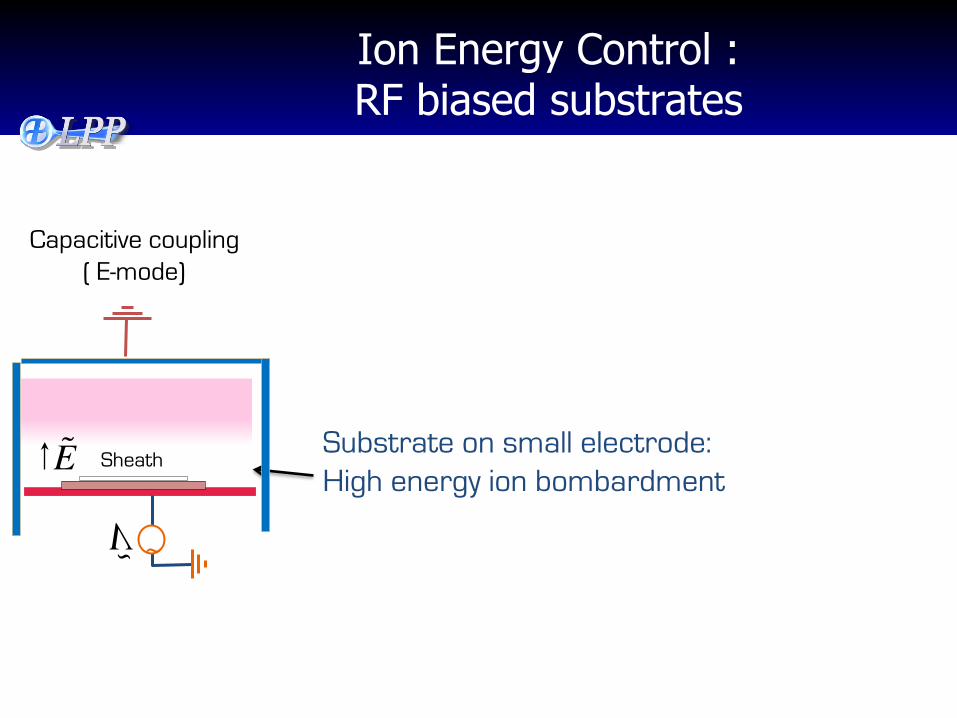
Ion Energy Control : RF biased substrates
Capacitive coupling ( E-mode)
Substrate on small electrode: High energy ion bombardment ~ V
Sheath E
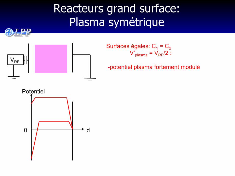
Reacteurs grand surface: Plasma symétrique
VRF
Potentiel
d 0
Surfaces égales: C1 = C2 V’plasma = VRF/2 :
-potentiel plasma fortement modulé
Laboratoire de Physique des Plasmas
Effects of frequency
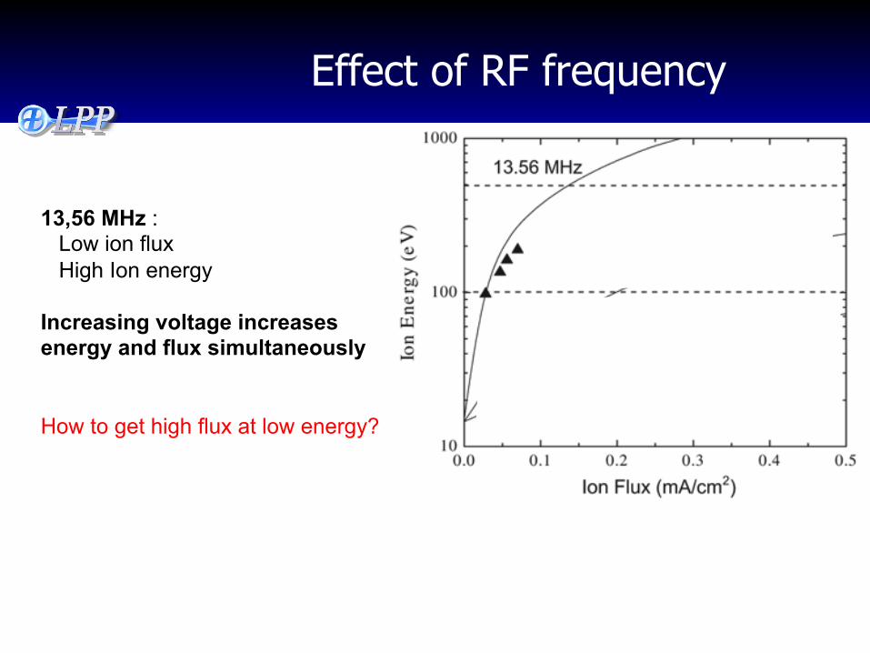
Effect of RF frequency
13,56 MHz : Low ion flux High Ion energy Increasing voltage increases energy and flux simultaneously How to get high flux at low energy?
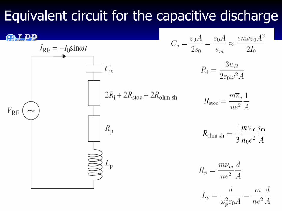
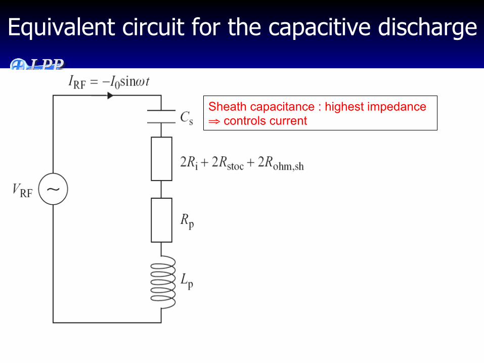
Equivalent circuit for the capacitive discharge
Equivalent circuit for the capacitive discharge
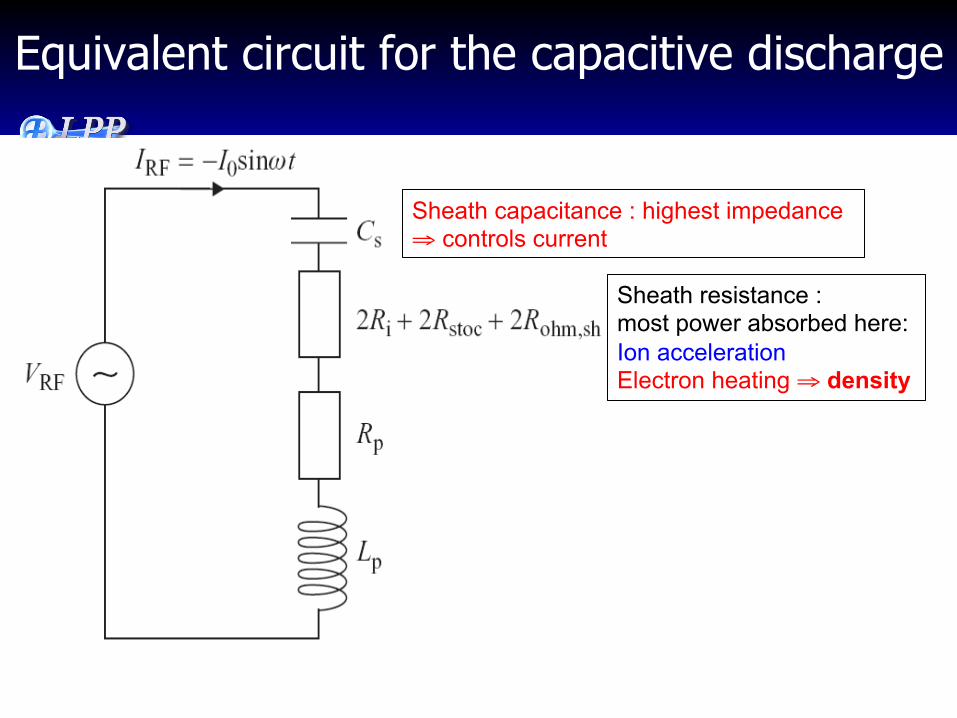
Sheath capacitance : highest impedance ⇒ controls current
Equivalent circuit for the capacitive discharge
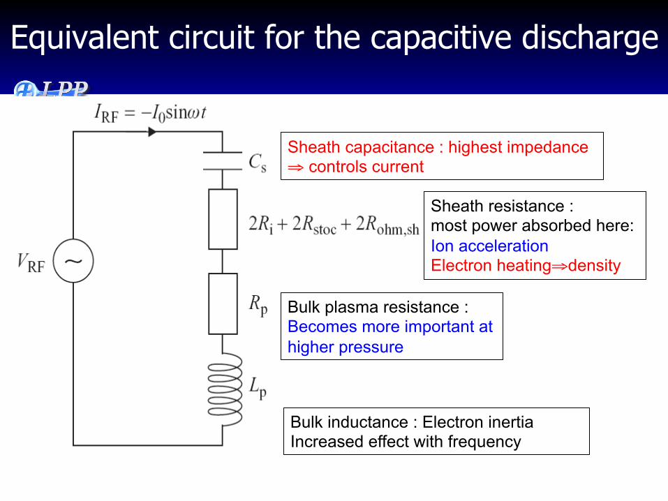
Sheath capacitance : highest impedance ⇒ controls current
Sheath resistance : most power absorbed here: Ion acceleration Electron heating ⇒ density
Equivalent circuit for the capacitive discharge
Sheath capacitance : highest impedance ⇒ controls current
Sheath resistance : most power absorbed here: Ion acceleration Electron heating⇒density
Bulk plasma resistance : Becomes more important at higher pressure
Bulk inductance : Electron inertia Increased effect with frequency
Effect of RF frequency
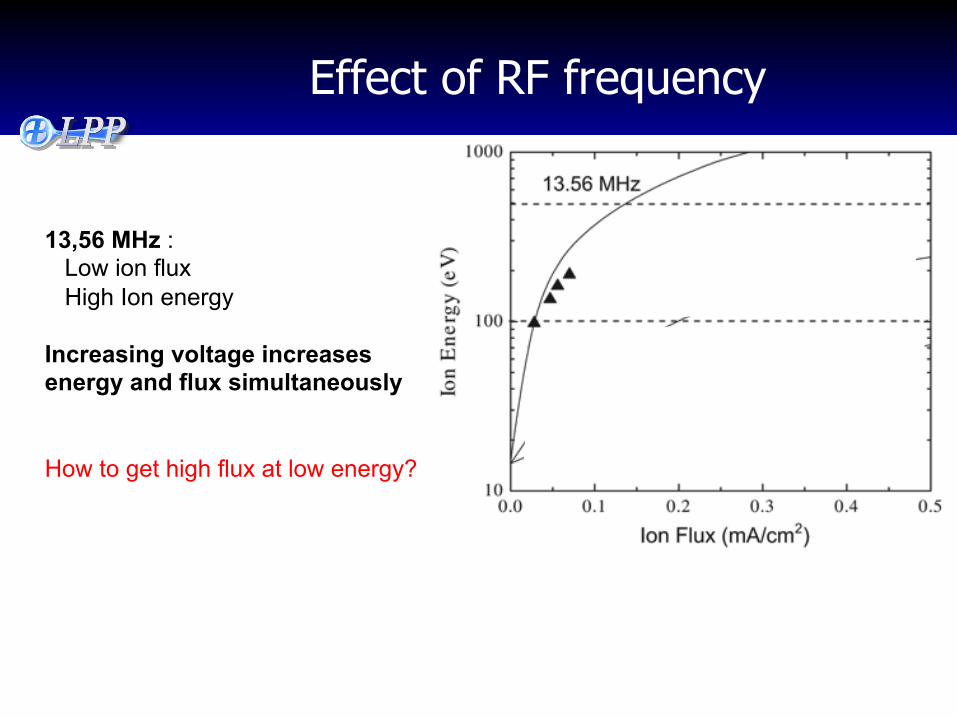
13,56 MHz : Low ion flux High Ion energy Increasing voltage increases energy and flux simultaneously How to get high flux at low energy?
Effect of RF frequency
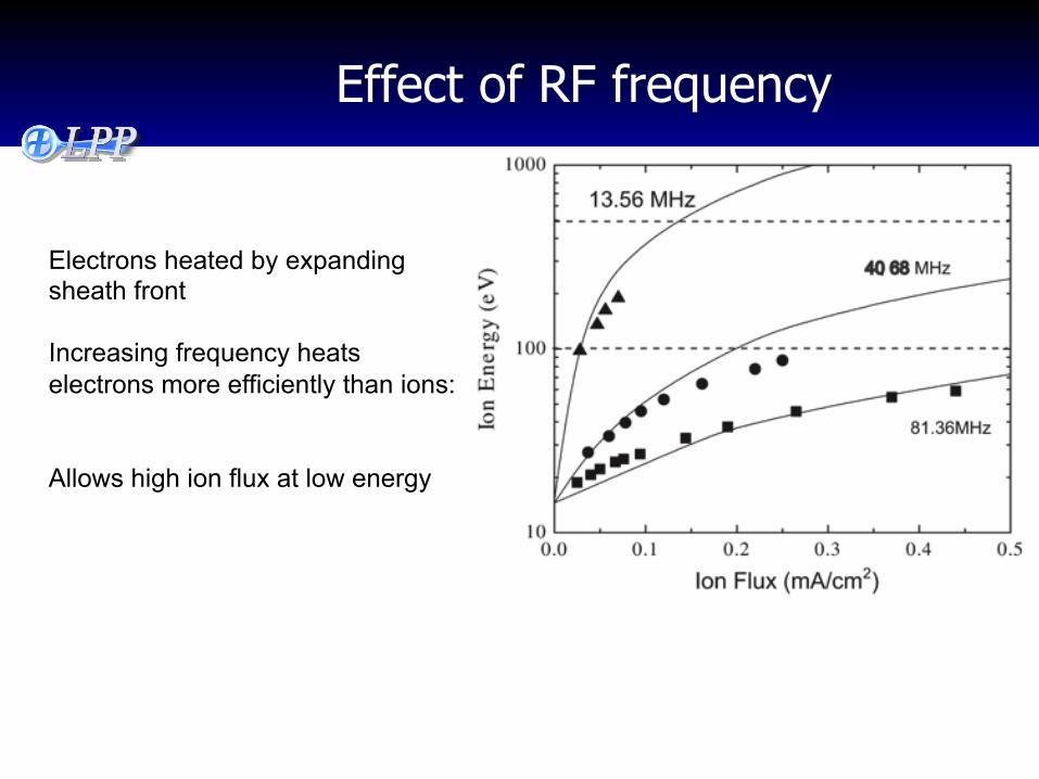
Electrons heated by expanding sheath front Increasing frequency heats electrons more efficiently than ions: Allows high ion flux at low energy
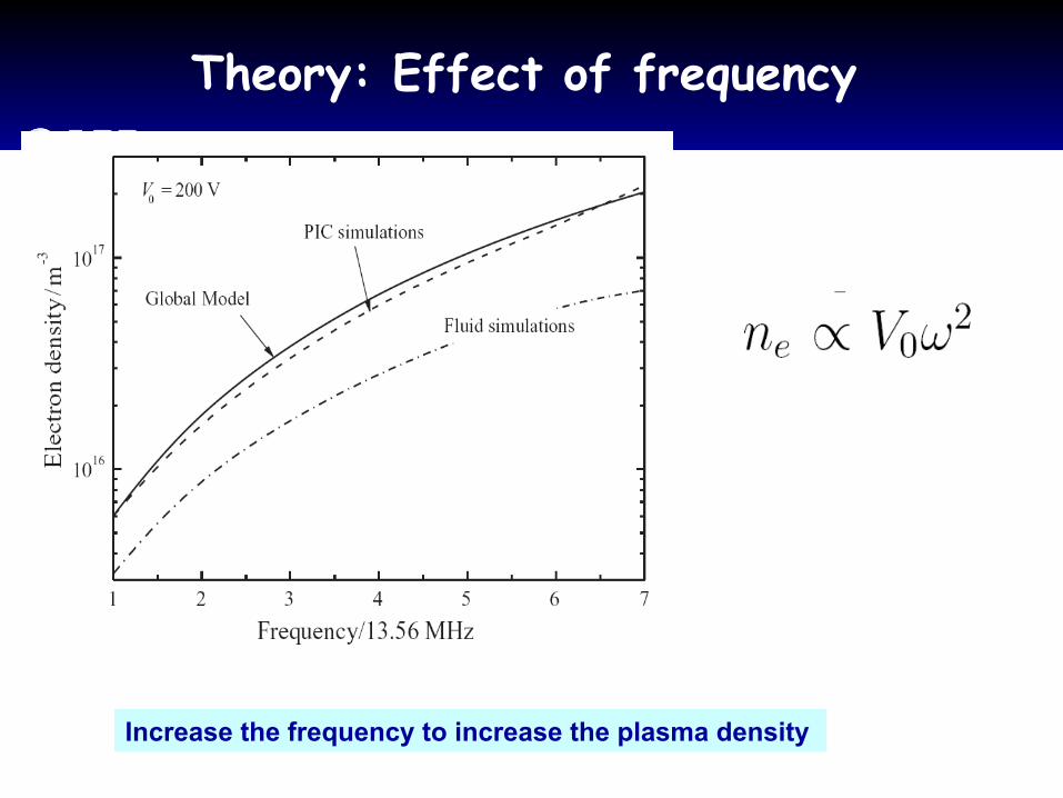
Theory: Effect of frequency
Increase the frequency to increase the plasma density
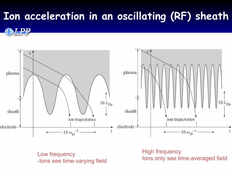
Ion acceleration in an oscillating (RF) sheath
Low frequency -Ions see time-varying field
High frequency Ions only see time-averaged field
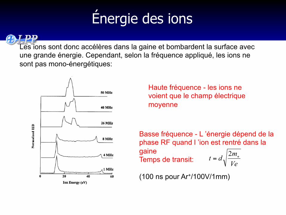
Énergie des ions
Les ions sont donc accélères dans la gaine et bombardent la surface avec une grande énergie. Cependant, selon la fréquence appliqué, les ions ne sont pas mono-énergétiques:
Basse fréquence - L ’énergie dépend de la phase RF quand l ’ion est rentré dans la gaine Temps de transit: (100 ns pour Ar+/100V/1mm)
Haute fréquence - les ions ne voient que le champ électrique moyenne
Vemdt +=2
0,0 0,1 0,2 0,3 0,4 0,510
100
1000
13.56 MHz
40.68 MHz
81.36 MHz
Ene
rgie
des
ions
(V
)
Flux d'ions Ji (mA.cm-2)
15 mTorr
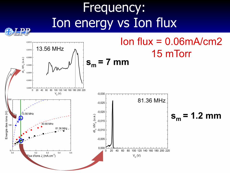
Frequency: Ion energy vs Ion flux
Ion flux = 0.06mA/cm2 15 mTorr
0 20 40 60 80 100 120 140 160 180 200 2200,000
-0,005
-0,010
-0,015
-0,020
-0,025
-0,030
dIC /d
VD (
u.a.
)
VD (V)
Derivative of Data32_Coll
81.36 MHz
sm = 1.2 mm
0 20 40 60 80 100 120 140 160 180 200 2200,0000
-0,0002
-0,0004
-0,0006
-0,0008
-0,0010
-0,0012
dIC /d
VD (
u.a.
)
VD (V)
Derivative of Smoothed1_Data1Coll
13.56 MHz
sm = 7 mm
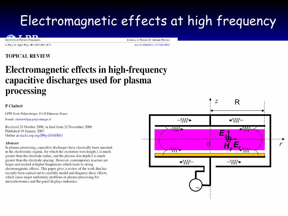
Electromagnetic effects at high frequency
~
z
r 0
R
Hφ
Ez
Er
r
z
Field line E
Field line B
E0 B1 E1
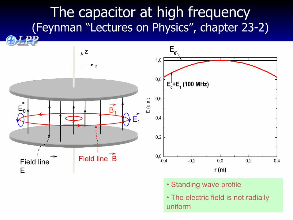
-0,4 -0,2 0,0 0,2 0,40,0
0,2
0,4
0,6
0,8
1,0
E0+E1 (100 MHz)
E (u
.a.)
r (m)
E0
• Standing wave profile
• The electric field is not radially uniform
The capacitor at high frequency (Feynman “Lectures on Physics”, chapter 23-2)
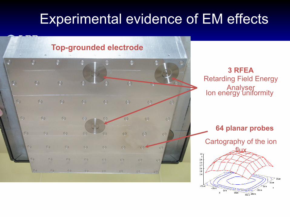
Experimental evidence of EM effects
Top-grounded electrode
64 planar probes
Cartography of the ion flux
3 RFEA Retarding Field Energy
Analyser Ion energy uniformity
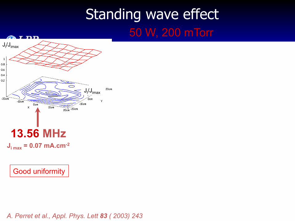
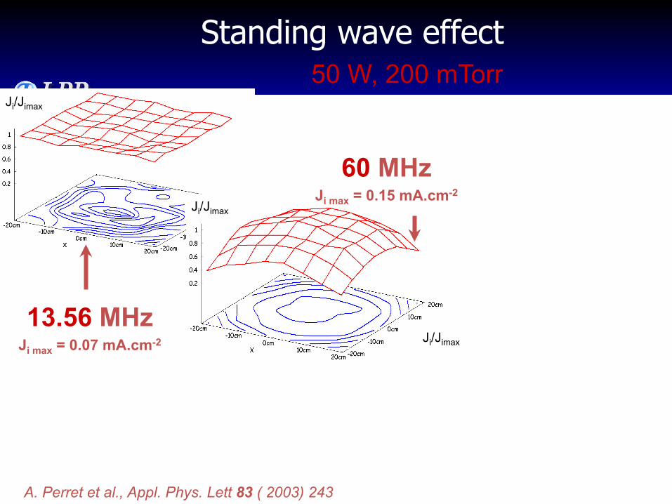
Standing wave effect
13.56 MHz Ji max = 0.07 mA.cm-2
50 W, 200 mTorr Ji/Jimax
Ji/Jimax
A. Perret et al., Appl. Phys. Lett 83 ( 2003) 243
Good uniformity
Standing wave effect
13.56 MHz Ji max = 0.07 mA.cm-2
50 W, 200 mTorr Ji/Jimax
Ji/Jimax
Ji/Jimax
60 MHz Ji max = 0.15 mA.cm-2
A. Perret et al., Appl. Phys. Lett 83 ( 2003) 243
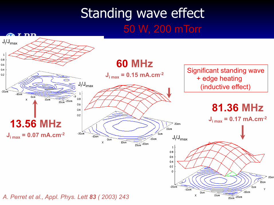
Standing wave effect
13.56 MHz Ji max = 0.07 mA.cm-2
50 W, 200 mTorr Ji/Jimax
Ji/Jimax
Ji/Jimax
60 MHz Ji max = 0.15 mA.cm-2
81.36 MHz Ji max = 0.17 mA.cm-2
A. Perret et al., Appl. Phys. Lett 83 ( 2003) 243
Significant standing wave + edge heating (inductive effect)
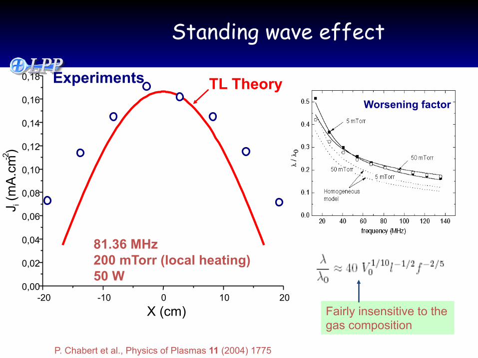
-20 -10 0 10 20 0,00
0,02
0,04
0,06
0,08
0,10
0,12
0,14
0,16
0,18 Experiments
J i (m
A.c
m -2 )
X (cm)
TL Theory
Standing wave effect
81.36 MHz 200 mTorr (local heating) 50 W
P. Chabert et al., Physics of Plasmas 11 (2004) 1775
Worsening factor
Fairly insensitive to the gas composition
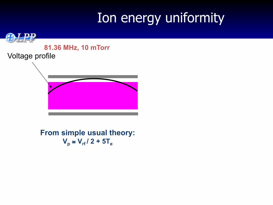
Ion energy uniformity
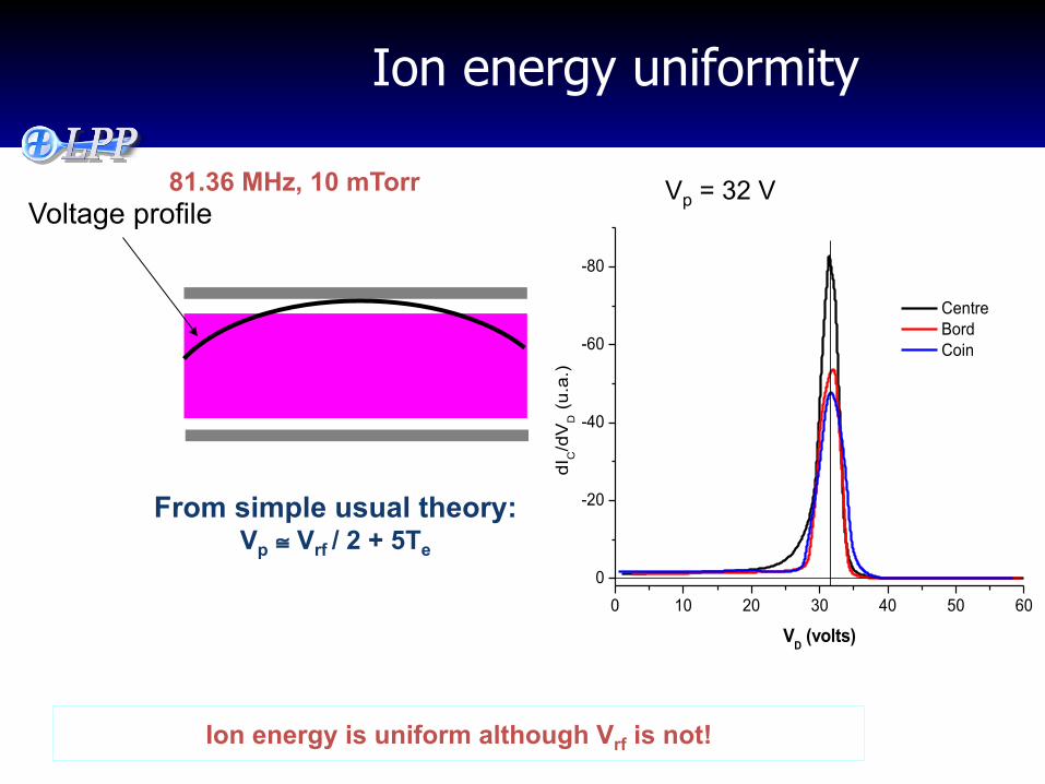
81.36 MHz, 10 mTorr
Voltage profile
From simple usual theory: Vp ≅ Vrf / 2 + 5Te
Ion energy uniformity
0 10 20 30 40 50 60
0
-20
-40
-60
-80
dIC/d
VD (
u.a.
)
VD (volts)
Centre Bord Coin
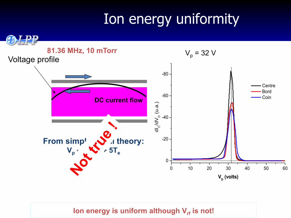
81.36 MHz, 10 mTorr Vp = 32 V Voltage profile
From simple usual theory: Vp ≅ Vrf / 2 + 5Te
Ion energy is uniform although Vrf is not!
Ion energy uniformity
0 10 20 30 40 50 60
0
-20
-40
-60
-80
dIC/d
VD (
u.a.
)
VD (volts)
Centre Bord Coin
81.36 MHz, 10 mTorr Vp = 32 V Voltage profile
From simple usual theory: Vp ≅ Vrf / 2 + 5Te
DC current flow
Ion energy is uniform although Vrf is not!
Laboratoire de Physique des Plasmas
L’excitation multifréquence: non-synchronisée
Comment contrôler indépendamment le flux et l’énergie des ions?
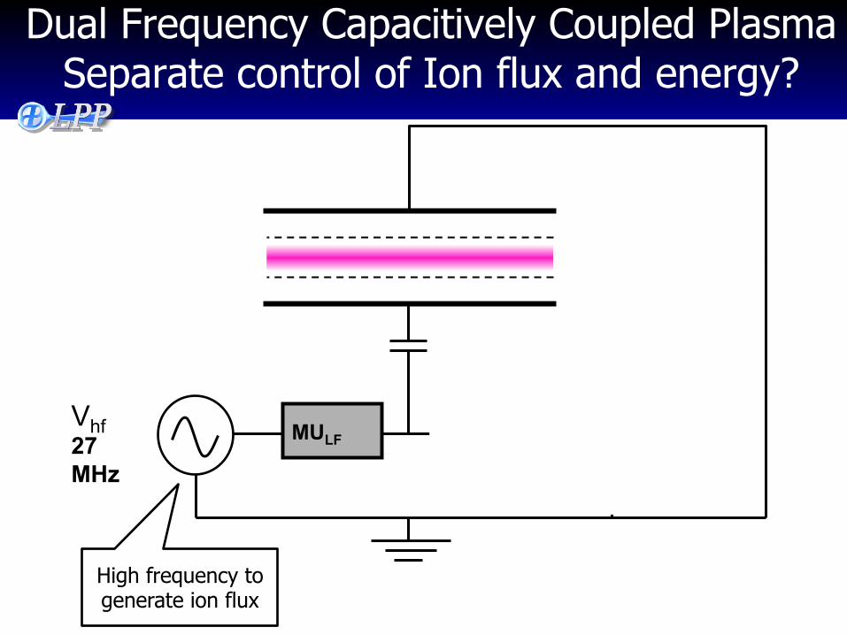
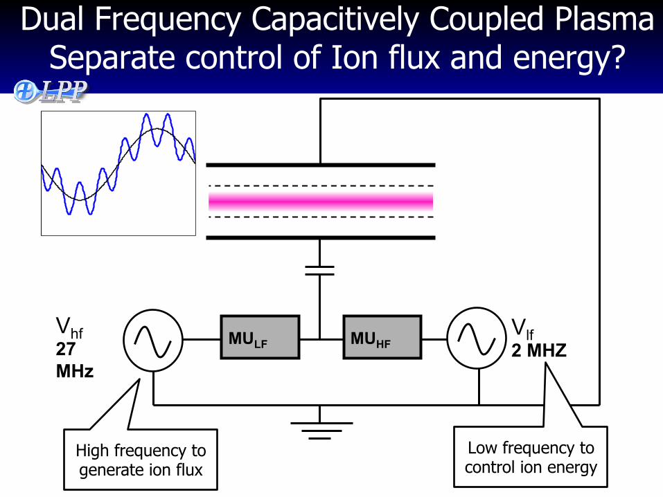
Dual Frequency Capacitively Coupled Plasma Separate control of Ion flux and energy?
Vhf 27 MHz
Vlf 2 MHZ
MULF MUHF
High frequency to generate ion flux
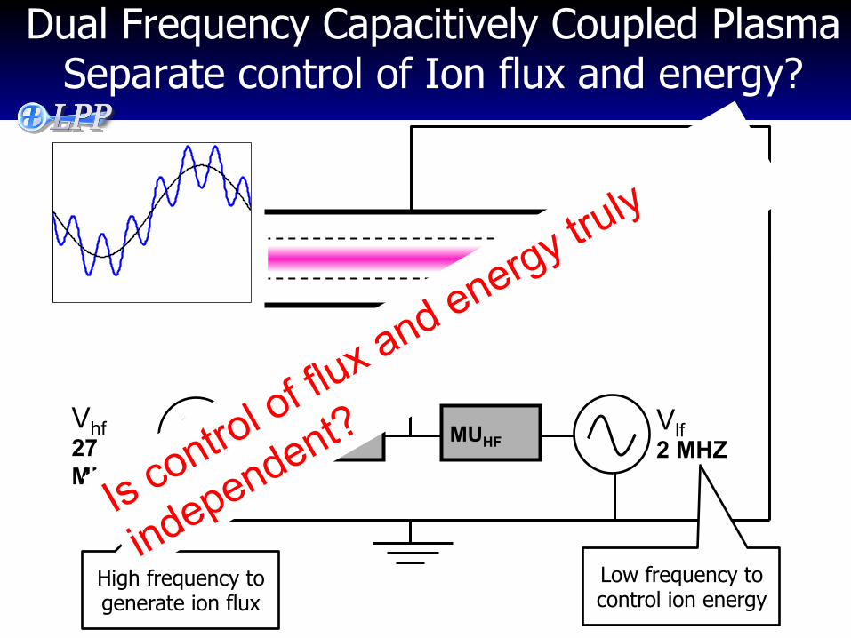
Dual Frequency Capacitively Coupled Plasma Separate control of Ion flux and energy?
Vhf 27 MHz
Vlf 2 MHZ
MULF MUHF
Low frequency to control ion energy
High frequency to generate ion flux
Dual Frequency Capacitively Coupled Plasma Separate control of Ion flux and energy?
Vhf 27 MHz
Vlf 2 MHZ
MULF MUHF
Low frequency to control ion energy
High frequency to generate ion flux
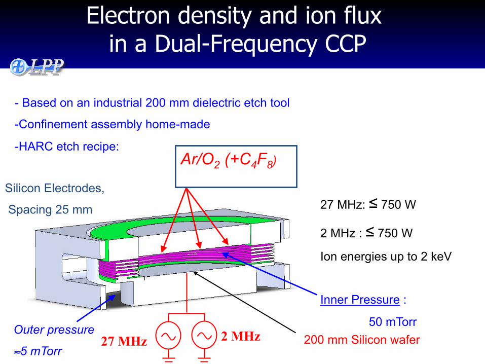
Electron density and ion flux in a Dual-Frequency CCP
27 MHz 2 MHz 200 mm Silicon wafer
Silicon Electrodes,
Spacing 25 mm
- Based on an industrial 200 mm dielectric etch tool
- Confinement assembly home-made
- HARC etch recipe: Ar/O2 (+C4F8)
27 MHz: ≤ 750 W
2 MHz : ≤ 750 W
Ion energies up to 2 keV
Inner Pressure :
50 mTorr Outer pressure
≈5 mTorr
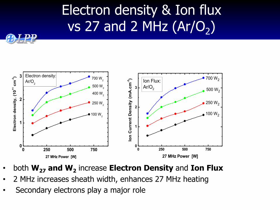
Electron density & Ion flux vs 27 and 2 MHz (Ar/O2)
• both W27 and W2 increase Electron Density and Ion Flux • 2 MHz increases sheath width, enhances 27 MHz heating • Secondary electrons play a major role
0 250 500 7500
1
2
3
100 W2
400 W2
250 W2
500 W2
Ele
ctro
n de
nsity
, (10
11 c
m-3)
27 MHz Power [W]
700 W2Electron density:Ar/O2
0 250 500 7500
1
2
3
100 W2
250 W2
500 W2
Ion
Cur
rent
Den
sity
(m
A.c
m-2)
27 MHz Power [W]
700 W2Ion Flux:Ar/O2
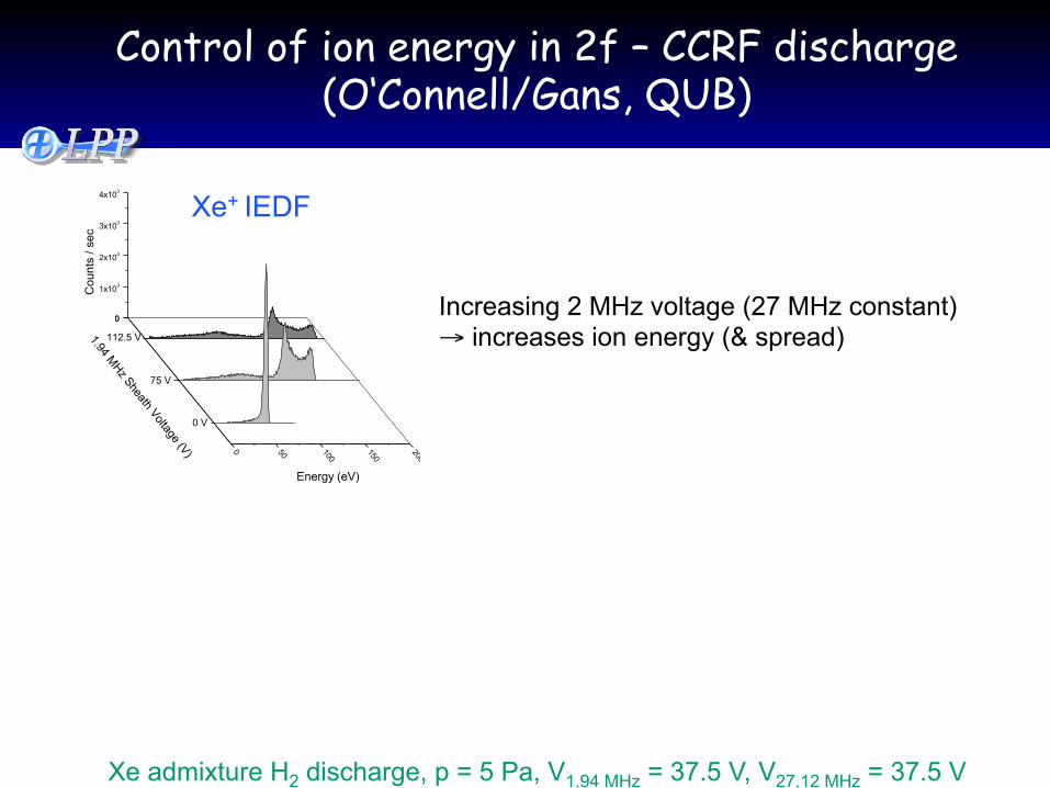
Control of ion energy in 2f – CCRF discharge (O‘Connell/Gans, QUB)
00
1x10³
2x10³
3x10³
4x10³
0 50 100
150
200
Energy (eV)
Cou
nts
/ sec
1.94 MHz Sheath Voltage (V)
112.5 V
75 V
0 V
Xe admixture H2 discharge, p = 5 Pa, V1.94 MHz = 37.5 V, V27.12 MHz = 37.5 V
Xe+ IEDF
Increasing 2 MHz voltage (27 MHz constant) → increases ion energy (& spread)
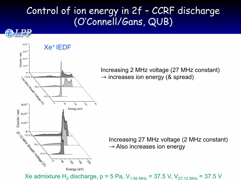
Control of ion energy in 2f – CCRF discharge (O‘Connell/Gans, QUB)
00
1x10³
2x10³
3x10³
0 50 100
150
200
Energy (eV)
Cou
nts
/ sec
27.12 MHz Sheath Voltage (V)
112.5 V
75 V
37.5 V
00
1x10³
2x10³
3x10³
4x10³
0 50 100
150
200
Energy (eV)
Cou
nts
/ sec
1.94 MHz Sheath Voltage (V)
112.5 V
75 V
0 V
Xe admixture H2 discharge, p = 5 Pa, V1.94 MHz = 37.5 V, V27.12 MHz = 37.5 V
Xe+ IEDF
Increasing 2 MHz voltage (27 MHz constant) → increases ion energy (& spread)
Increasing 27 MHz voltage (2 MHz constant) → Also increases ion energy
DF-CCP Summary
• Use of dual (or even triple) frequency allows access to a wide range of ion flux/ energy not available with single frequency
• Ion energy distribution functions : wide, complex (But may be useful for processing..)
• Low frequency power nevertheless also increases flux
• High frequency power also increases ion energy
Laboratoire de Physique des Plasmas
L’excitation multifréquence synchronisée: les formes d’onde « sur-mesure »
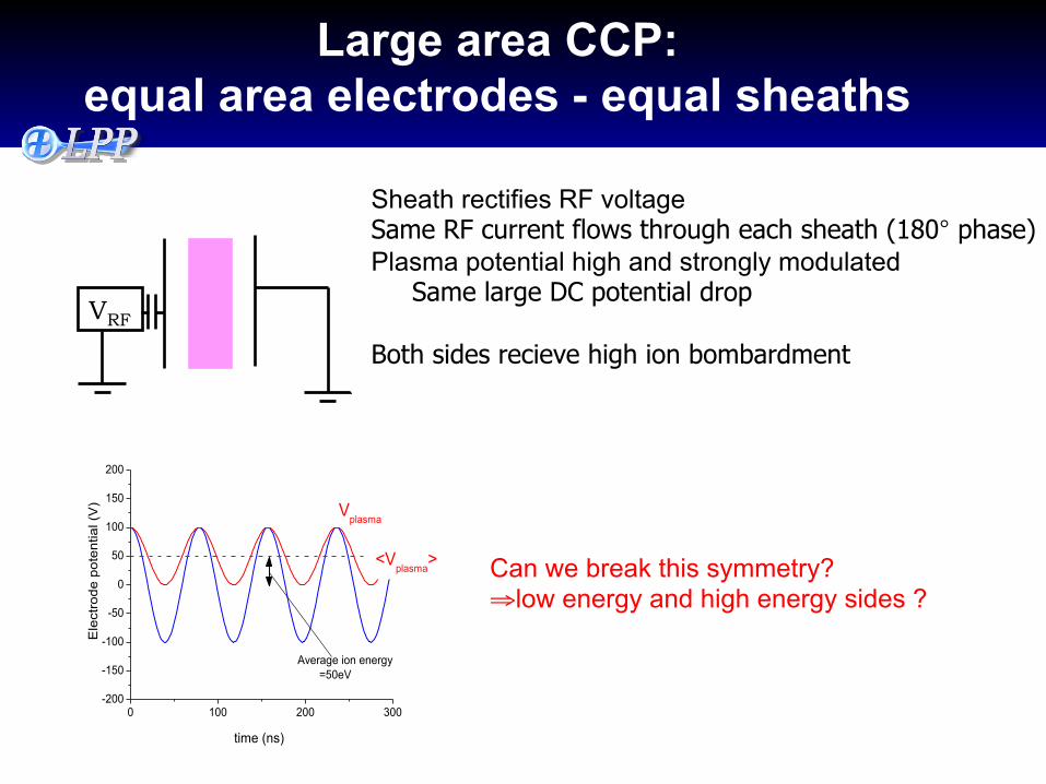
0 100 200 300-200
-150
-100
-50
0
50
100
150
200
<Vplasma
>
Vplasma
Ele
ctro
de p
oten
tial (
V)
time (ns)
Average ion energy =50eV
VRF
Sheath rectifies RF voltage Same RF current flows through each sheath (180° phase) Plasma potential high and strongly modulated Same large DC potential drop Both sides recieve high ion bombardment
Large area CCP: equal area electrodes - equal sheaths
Can we break this symmetry? ⇒low energy and high energy sides ?
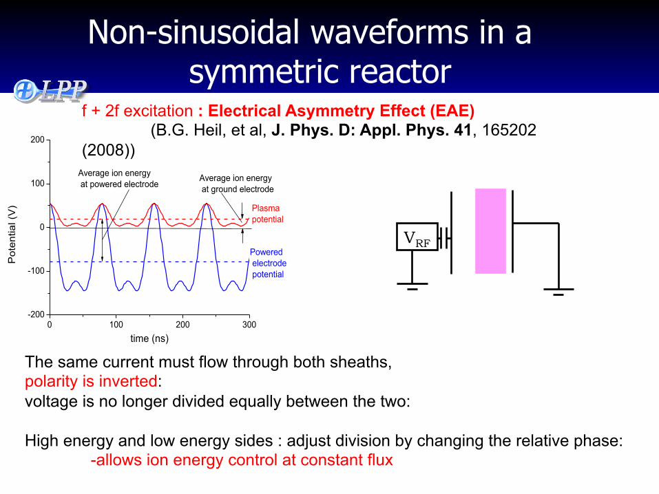
The same current must flow through both sheaths, polarity is inverted: voltage is no longer divided equally between the two: High energy and low energy sides : adjust division by changing the relative phase:
-allows ion energy control at constant flux
VRF
0 100 200 300-200
-100
0
100
200
Average ion energy at ground electrode
Pot
entia
l (V
)
time (ns)
Average ion energy at powered electrode
Plasma potential
Powered electrode potential
f + 2f excitation : Electrical Asymmetry Effect (EAE) (B.G. Heil, et al, J. Phys. D: Appl. Phys. 41, 165202 (2008))
Non-sinusoidal waveforms in a symmetric reactor
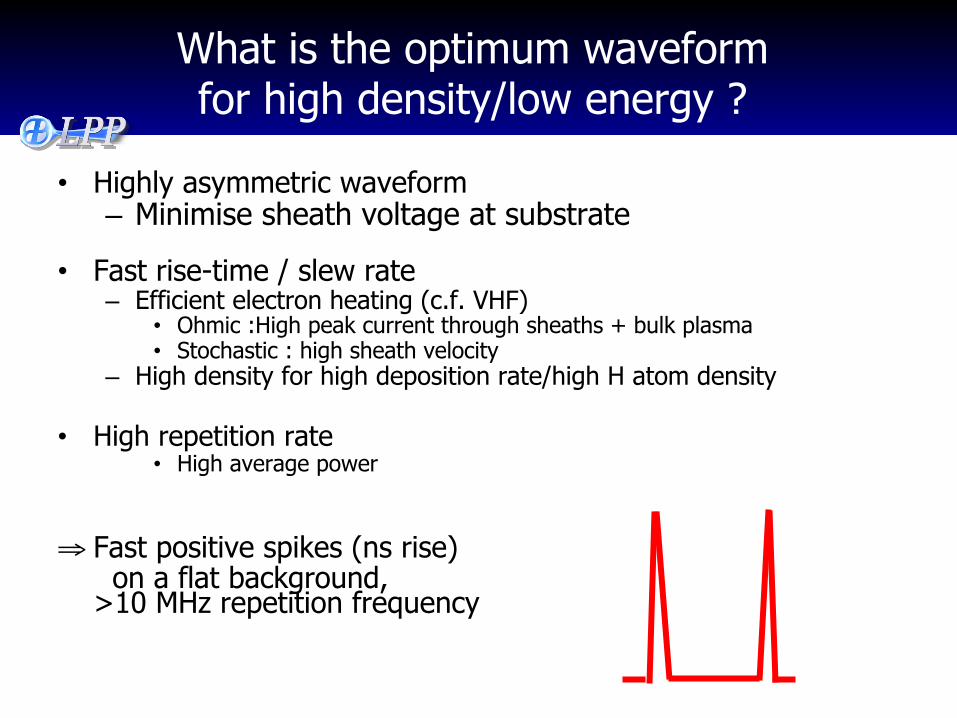
What is the optimum waveform for high density/low energy ?
• Highly asymmetric waveform – Minimise sheath voltage at substrate
• Fast rise-time / slew rate – Efficient electron heating (c.f. VHF)
• Ohmic :High peak current through sheaths + bulk plasma • Stochastic : high sheath velocity
– High density for high deposition rate/high H atom density
• High repetition rate • High average power
⇒ Fast positive spikes (ns rise) on a flat background,
>10 MHz repetition frequency
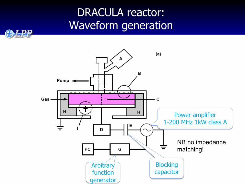
DRACULA reactor: Waveform generation
Power amplifier 1-200 MHz 1kW class A
Arbitrary function
generator
Blocking capacitor
NB no impedance matching!
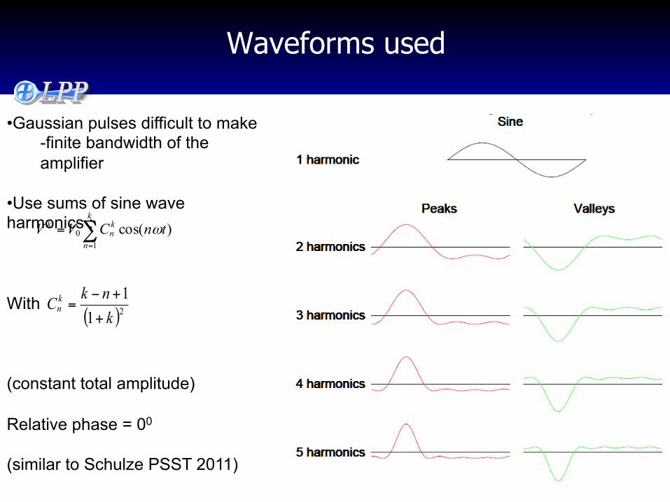
• Gaussian pulses difficult to make -finite bandwidth of the amplifier
• Use sums of sine wave harmonics :
With
(constant total amplitude) Relative phase = 00
(similar to Schulze PSST 2011)
∑=
=k
n
kn
k tnCVV1
0 )cos( ω
( )211
knkCk
n+
+−=
Waveforms used
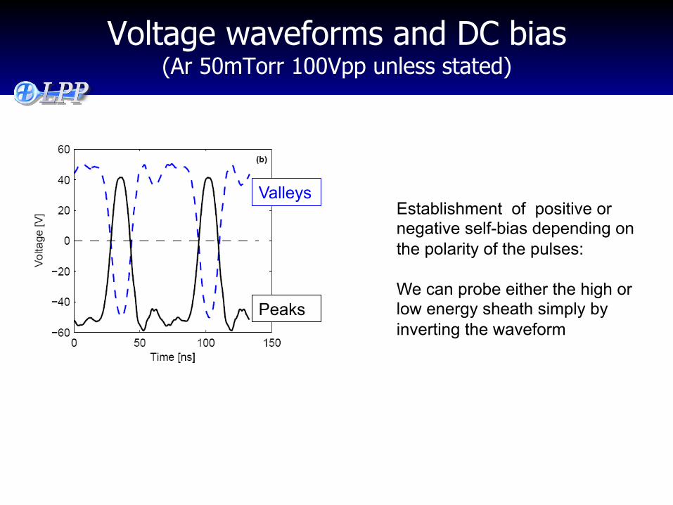
Voltage waveforms and DC bias (Ar 50mTorr 100Vpp unless stated)
Peaks
Valleys Establishment of positive or negative self-bias depending on the polarity of the pulses: We can probe either the high or low energy sheath simply by inverting the waveform
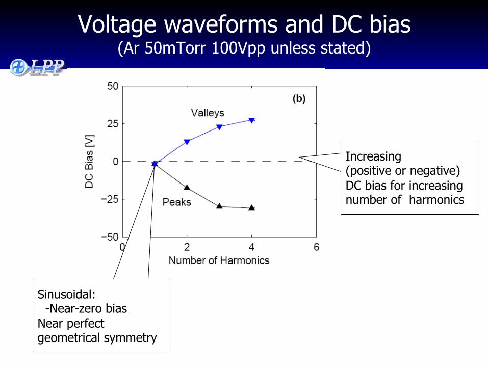
Voltage waveforms and DC bias (Ar 50mTorr 100Vpp unless stated)
Sinusoidal: -Near-zero bias Near perfect geometrical symmetry
Increasing (positive or negative) DC bias for increasing number of harmonics
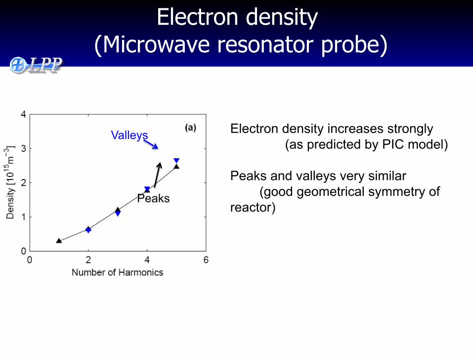
Electron density (Microwave resonator probe)
Electron density increases strongly (as predicted by PIC model) Peaks and valleys very similar (good geometrical symmetry of reactor)
Valleys
Peaks
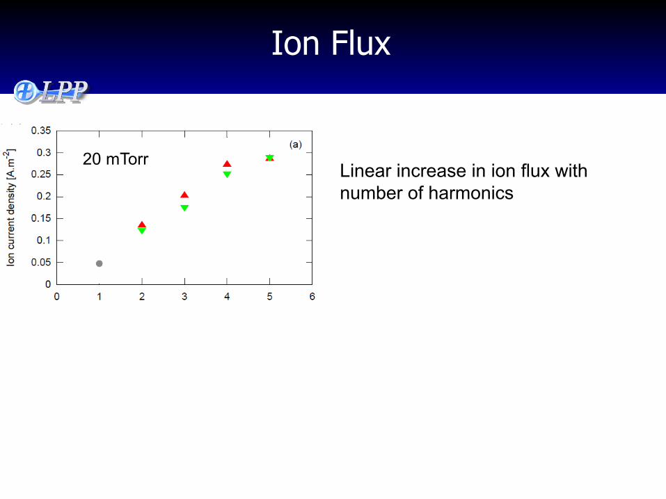
20 mTorr Linear increase in ion flux with number of harmonics
Ion Flux
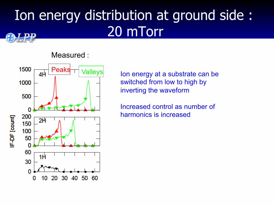
Measured :
Peaks Valleys Ion energy at a substrate can be switched from low to high by inverting the waveform Increased control as number of harmonics is increased
Ion energy distribution at ground side : 20 mTorr
Can we break the ion FLUX symmetry?
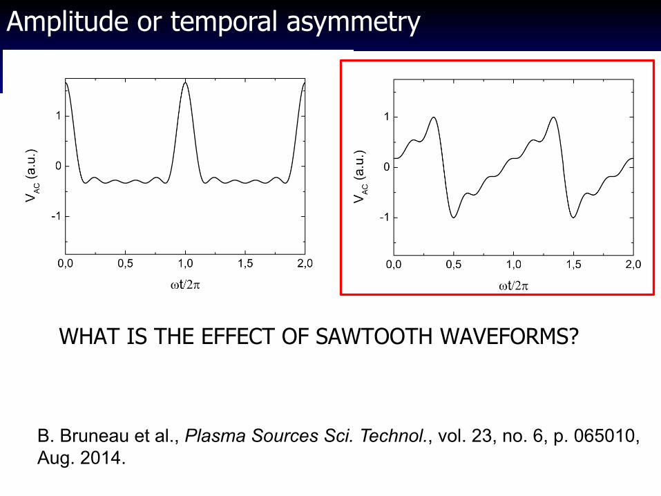
WHAT IS THE EFFECT OF SAWTOOTH WAVEFORMS?
B. Bruneau et al., Plasma Sources Sci. Technol., vol. 23, no. 6, p. 065010, Aug. 2014.
Amplitude or temporal asymmetry

Bastien Bruneau – 12/11/2014 6
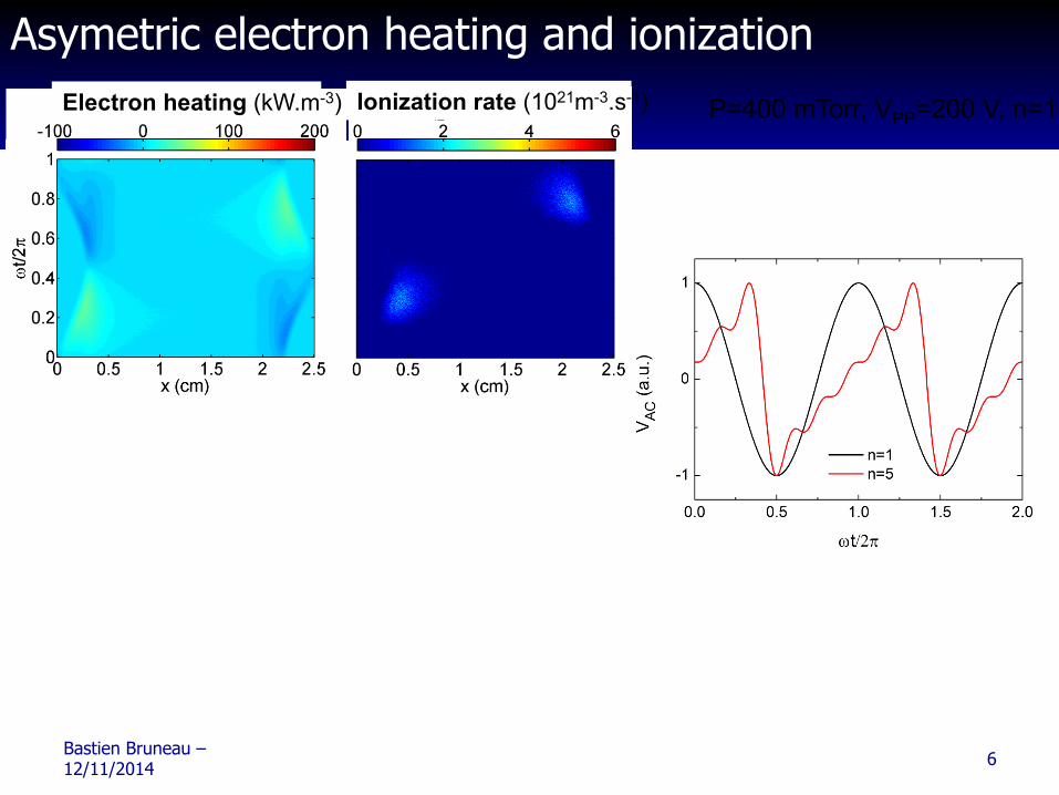
Asymetric electron heating and ionization Ionization rate (1021m-3.s-1) Electron heating (kW.m-3) P=400 mTorr, VPP=200 V, n=1-5
Bastien Bruneau – 12/11/2014 6
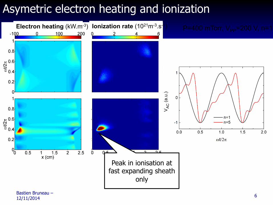
Asymetric electron heating and ionization Ionization rate (1021m-3.s-1) Electron heating (kW.m-3) P=400 mTorr, VPP=200 V, n=1-5
Bastien Bruneau – 12/11/2014 6
Asymetric electron heating and ionization Ionization rate (1021m-3.s-1) Electron heating (kW.m-3) P=400 mTorr, VPP=200 V, n=1-5
Peak in ionisation at fast expanding sheath
only
Bastien Bruneau – 12/11/2014 8 P=400 mTorr, VPP=200 V, n=1-5
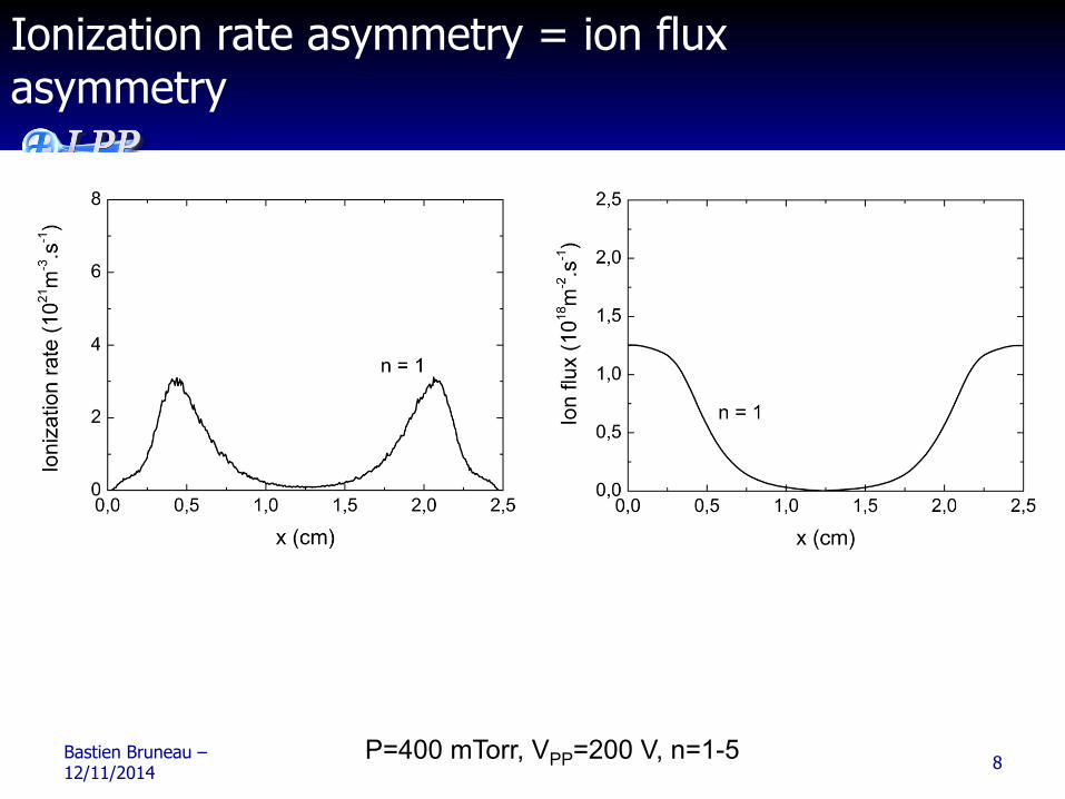
Ionization rate asymmetry = ion flux asymmetry
Bastien Bruneau – 12/11/2014 8 P=400 mTorr, VPP=200 V, n=1-5
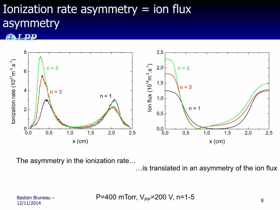
Ionization rate asymmetry = ion flux asymmetry
…is translated in an asymmetry of the ion flux The asymmetry in the ionization rate…
Bibliography
• Physics of Radiofrequency Plasmas P. Chabert and N. Braithwaite, Cambridge University Press, 2011
• Principles of Plasma Discharges and Materials Processing, M.A.Lieberman and A.J.Lichtenberg, 2nd Edition, John Wiley and Sons Inc.,
New York, 2005 • Fields and Waves in Communication, S. Ramo, J. R. Whinnery, and T. Vanduzer, Electronics, 3rd ed., John Wiley and Sons Inc., New York, 1994