PhysTech-2005-6-dc-pulsed magnetron · PDF file · 2012-03-31j n e exp 8 4 1 0 m e...
10
Herstellen Dünner Schichten - Aufdampfen/Kondensieren 2005-1 PhysTech Coating Technology GmbH 1 Publikationen 2005-6 Plasma investigations of dc and dc pulsed magnetron sputter processes Georg N. Strauss Stefan Schlichtherle PhysTech Coating Technology GmbH Pflach/Austria Hans K. Pulker Institut für Ionenphysik, AG: Dünnschichttechnologie Universität Innsbruck, Innsbruck/Austria PhysTech Coating Technology GmbH Kohlplatz 7, Innovationszentrum A-6600 Pflach [email protected] www.phystech-coating.com
Transcript of PhysTech-2005-6-dc-pulsed magnetron · PDF file · 2012-03-31j n e exp 8 4 1 0 m e...
Herstellen Dünner Schichten - Aufdampfen/Kondensieren
2005-1 PhysTech Coating Technology GmbH 1
Publikationen 2005-6 Plasma investigations of dc and dc
pulsed magnetron sputter processes
Georg N. Strauss
Stefan Schlichtherle PhysTech Coating Technology GmbH
Pflach/Austria
Hans K. Pulker Institut für Ionenphysik, AG: Dünnschichttechnologie
Universität Innsbruck, Innsbruck/Austria
PhysTech Coating Technology GmbH Kohlplatz 7, Innovationszentrum A-6600 Pflach [email protected] www.phystech-coating.com
Plasma analysis of DC and DC pulsed magnetron sputtering
2 PhysTech Coating Technology GmbH 2005-6
Plasma investigation of DC and DC pulsed magnetron sputter processes Georg N. Strauss1, Stefan Schlichtherle1, Hans K. Pulker2 1 PhysTech Coating Technology GmbH, Kohlplatz 7, Innovationszentrum, A-6600 Pflach email: [email protected], Internet: www.phystech-coating.com 2 University of Innsbruck, Institute of Ion Physics, Technikerstrasse 25, A-6020 Innsbruck
Abstract: The plasma of different dc and dc pulsed pvd processes (TiN, CrN, Ta2O5) has been investigated by means of a plasma monitoring system PPM421. The system consists of a quadrupol mass spectrometer with an additional energy analyzer and gives the possibility to determine the kind of the process ions and their energy distribution. The ion energy distribution of the process relevant ions has been measured and the dependence of the plasma properties on the process parameters like pulse frequency and pulse voltage is shown. Starting with a summarization concerning the theoretical concept behind the plasma properties in dc pulsed sputter processes, some predictions about the kinetic energy of the ions and the shape of the ion energy distribution are compared with the experimental results in different dc pulsed sputter processes. It can be seen that there is a significant difference in the ion energy distribution in standard dc magnetron processes compared to dc pulsed processes and the process parameters pulse frequency and pulse voltage give a good possibility to control the kinetic energy of the process ions. 1. Introduction: In generating and sustaining plasmas, energy is imparted to electrons by electric fields and the energetic electrons create ionization by electron-atom impact. Electrons in a plasma originate from secondary electrons from an ion or electron bombarded surface (secondary electron emission), ionizing collisions and electrons from a thermo-electron emitting source (hot cathode). The typical configurations associated with the technique referred to as diode sputtering is to apply a high voltage (200V to over 1000V) between two electrodes. If proper conditions are met (electric field, gas pressure) a discharge will occur, generating a plasma. Ions extracted from the plasma will be accelerated towards the cathode (sputtering target) and will bombard the surface, sputtering the cathode material. The ions also will experience physical collisions in the gas phase and lose some of their kinetic energy. Some of the ions being accelerated to the cathode may become neutralized by charge-exchange processes and this produces a spectrum of high energy neutral species. Depending on the mode of operation, the plasma is divided into different sections, depending on the specific phenomena that occur in these regions. Pulsed sputtering has been introduced to stabilize reactive magnetron deposition processes. During recent years several investigations have indicated that pulsed powering not only remarkably improves the process stability, but also increases energetic particle bombardment of the substrate and the growing film. Pulsed DC uses a potential in the range of 50 to 350 kHz where the voltage, pulse width, off time and pulse polarity can be varied. The pulse can be unipolar, where the voltage is typically negative with a no-voltage off-time, or bipolar where the voltage polarity alternates between negative and positiv. Pulsed power can be obtained by switching a continous DC or sinewave power supply, or can be obtained from a specially designed pulsed power supply that generally allows more flexibility as to waveform. 1.1. Theory: In this part a technique to predict the evolution of the potential of a surface exposed to the plasma and the current from the plasma inducing this potential evolution, which was mainly done by Edward V. Barnat and Toh-Ming Lu [1], is summarized, and the predicted energy spectra of the ions to the electrode in response to an applied pulse is compared with some measurements in different dc pulsed and dc biased magnetron sputter processes shown in the experimental part of this paper. Definition of the pulse:
Plasma analysis of DC and DC pulsed magnetron sputtering
2005-6 PhysTech Coating Technology GmbH 3
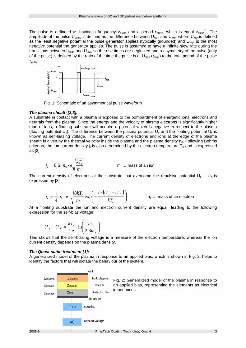
The pulse is definded as having a frequency νpulse and a period τpulse, which is equal νpulse-1. The
amplitude of the pulse Upulse is defined as the difference between Uhigh and Ulow, where Ulow is defined as the least negative potential the pulse generator applies (typically grounded) and Uhigh is the most negative potential the generator applies. The pulse is assumed to have a infinite slew rate during the transitions between Uhigh and Ulow, so the rise times are neglected and a asymmetry of the pulse (duty of the pulse) is defined by the ratio of the time the pulse is at Uhigh (τhigh) to the total period of the pulse τpulse.
Fig. 1: Schematic of an asymmetrical pulse waveform The plasma sheath [2,3]: A substrate in contact with a plasma is exposed to the bombardment of energetic ions, electrons and neutrals from the plasma. Since the energy and the velocity of plasma electrons is significantly higher than of ions, a floating substrate will acquire a potential which is negative in respect to the plasma (floating potential Ufl). The difference between the plasma potential Up and the floating potential Ufl is known as self-biasing voltage. The current density of electrons and ions at the edge of the plasma sheath is given by the thermal velocity inside the plasma and the plasma density n0. Following Bohms criterion, the ion current density ji is also determined by the electron temperature Te and is expressed as [3]:
i
ei m
kTenj ⋅⋅= 06,0 mi … mass of an ion
The current density of electrons at the substrate that overcome the repulsive potential Up – Ufl is expressed by [3]
( )⎟⎟⎠
⎞⎜⎜⎝
⎛ −⋅−⋅⋅=
e
flp
e
ee kT
UUemkT
enj exp8
41
0 me … mass of an electron
At a floating substrate the ion and electron current density are equal, leading to the following expression for the self-bias voltage:
⎟⎟⎠
⎞⎜⎜⎝
⎛⋅=−
e
ieflp m
me
kTUU
3,2ln
2
This shows that the self-biasing voltage is a measure of the electron temperature, whereas the ion current density depends on the plasma density. The Quasi-static treatment [1]: A generalized model of the plasma in response to an applied bias, which is shown in Fig. 2, helps to identify the factors that will dictate the behaviour of the system.
Fig. 2: Generalized model of the plasma in response to an applied bias, representing the elements as electrical impedances
wall
bulk plasma
sheath
dielectric film
electrode
Uplasma
Usheath
Usurface
Zplasma
Zsheath
Zfilm
Zblock
U(t) applied voltage
coupling
Plasma analysis of DC and DC pulsed magnetron sputtering
4 PhysTech Coating Technology GmbH 2005-6
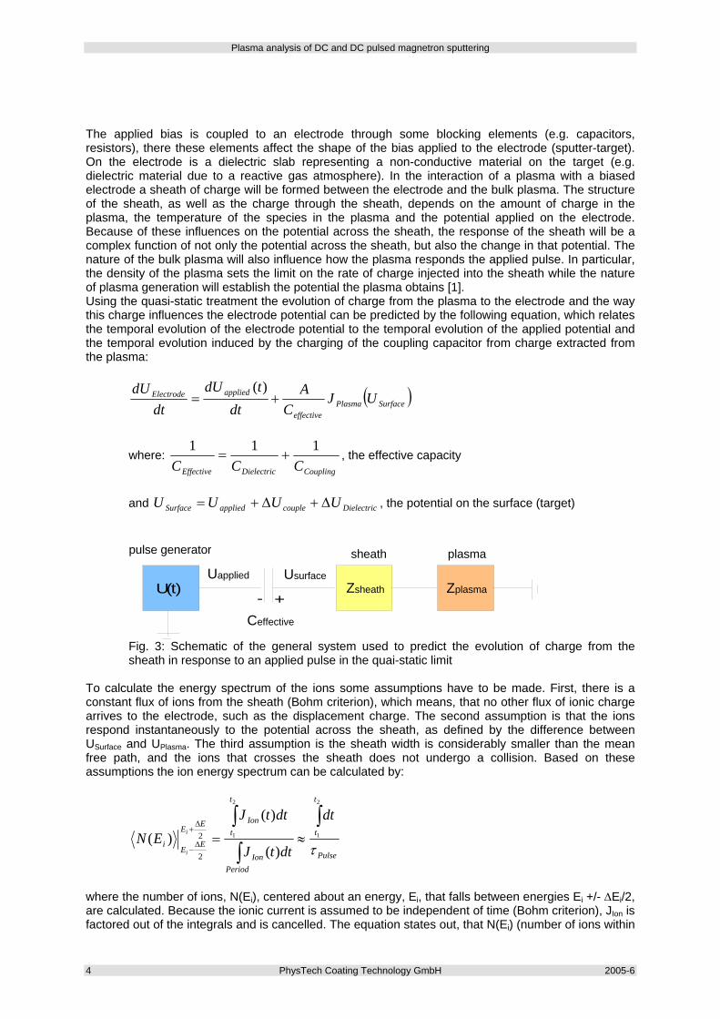
The applied bias is coupled to an electrode through some blocking elements (e.g. capacitors, resistors), there these elements affect the shape of the bias applied to the electrode (sputter-target). On the electrode is a dielectric slab representing a non-conductive material on the target (e.g. dielectric material due to a reactive gas atmosphere). In the interaction of a plasma with a biased electrode a sheath of charge will be formed between the electrode and the bulk plasma. The structure of the sheath, as well as the charge through the sheath, depends on the amount of charge in the plasma, the temperature of the species in the plasma and the potential applied on the electrode. Because of these influences on the potential across the sheath, the response of the sheath will be a complex function of not only the potential across the sheath, but also the change in that potential. The nature of the bulk plasma will also influence how the plasma responds the applied pulse. In particular, the density of the plasma sets the limit on the rate of charge injected into the sheath while the nature of plasma generation will establish the potential the plasma obtains [1]. Using the quasi-static treatment the evolution of charge from the plasma to the electrode and the way this charge influences the electrode potential can be predicted by the following equation, which relates the temporal evolution of the electrode potential to the temporal evolution of the applied potential and the temporal evolution induced by the charging of the coupling capacitor from charge extracted from the plasma:
( )SurfacePlasmaeffective
appliedElectrode UJC
Adt
tdUdt
dU+=
)(
where: CouplingDielectricEffective CCC
111+= , the effective capacity
and DielectriccoupleappliedSurface UUUU Δ+Δ+= , the potential on the surface (target)
U(t)
pulse generator
Ceffective
UsurfaceUapplied
- +
sheath plasma
Zsheath Zplasma
Fig. 3: Schematic of the general system used to predict the evolution of charge from the sheath in response to an applied pulse in the quai-static limit
To calculate the energy spectrum of the ions some assumptions have to be made. First, there is a constant flux of ions from the sheath (Bohm criterion), which means, that no other flux of ionic charge arrives to the electrode, such as the displacement charge. The second assumption is that the ions respond instantaneously to the potential across the sheath, as defined by the difference between USurface and UPlasma. The third assumption is the sheath width is considerably smaller than the mean free path, and the ions that crosses the sheath does not undergo a collision. Based on these assumptions the ion energy spectrum can be calculated by:
Pulse
t
t
PeriodIon
t
tIonEE
EEi
dt
dttJ
dttJEN i
i τ
∫
∫
∫≈=
Δ+
Δ−
2
1
2
1
)(
)()( 2
2
where the number of ions, N(Ei), centered about an energy, Ei, that falls between energies Ei +/- ΔEi/2, are calculated. Because the ionic current is assumed to be independent of time (Bohm criterion), JIon is factored out of the integrals and is cancelled. The equation states out, that N(Ei) (number of ions within
Plasma analysis of DC and DC pulsed magnetron sputtering
2005-6 PhysTech Coating Technology GmbH 5
a range of ΔE centered about Ei), is proportional to the fraction of time (per cycle) that the electrode potential resides in the range of Ei/e +/- ΔEi/e, with typically values of ΔE in the order of 1eV. This solution yields the temporal evolution of the current to the electrode and the temporal evolution of the electrode potential in response to this current.
ion energy
ion
coun
t (ar
b .)
low energy peak
high energy peak
width of low peak
width of high peak
Elow Ehigh
Fig. 4: Illustration of a generic energy spectra
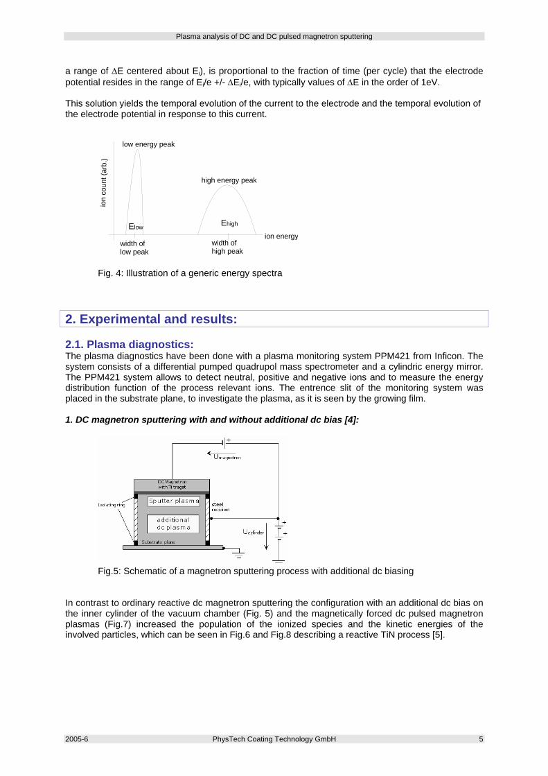
2. Experimental and results: 2.1. Plasma diagnostics: The plasma diagnostics have been done with a plasma monitoring system PPM421 from Inficon. The system consists of a differential pumped quadrupol mass spectrometer and a cylindric energy mirror. The PPM421 system allows to detect neutral, positive and negative ions and to measure the energy distribution function of the process relevant ions. The entrence slit of the monitoring system was placed in the substrate plane, to investigate the plasma, as it is seen by the growing film. 1. DC magnetron sputtering with and without additional dc bias [4]:
Fig.5: Schematic of a magnetron sputtering process with additional dc biasing In contrast to ordinary reactive dc magnetron sputtering the configuration with an additional dc bias on the inner cylinder of the vacuum chamber (Fig. 5) and the magnetically forced dc pulsed magnetron plasmas (Fig.7) increased the population of the ionized species and the kinetic energies of the involved particles, which can be seen in Fig.6 and Fig.8 describing a reactive TiN process [5].
Plasma analysis of DC and DC pulsed magnetron sputtering
6 PhysTech Coating Technology GmbH 2005-6
0 5 10 15 20 25 30 35 40 45 50 55 60102
103
104
105
106
107
Ti++
TiN++
Ti+
N+
TiN+
Ar+
Ar++
N2+
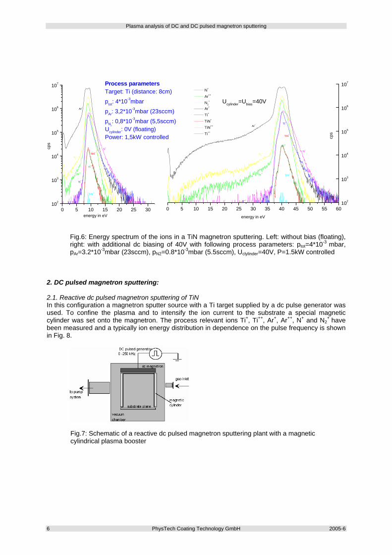
Process parametersTarget: Ti (distance: 8cm)
ptot: 4*10-3mbar
pAr: 3,2*10-3mbar (23sccm)
pN2: 0,8*10-3mbar (5,5sccm)
Ucylinder: 0V (floating)Power: 1,5kW controlled
cps
energy in eV
Fig.6: Energy spectrum of the ions in a TiN magnetron sputtering. Left: without bias (floating), right: with additional dc biasing of 40V with following process parameters: ptot=4*10-3 mbar, pAr=3.2*10-3mbar (23sccm), pN2=0.8*10-3mbar (5.5sccm), Uclylinder=40V, P=1.5kW controlled
2. DC pulsed magnetron sputtering: 2.1. Reactive dc pulsed magnetron sputtering of TiN In this configuration a magnetron sputter source with a Ti target supplied by a dc pulse generator was used. To confine the plasma and to intensify the ion current to the substrate a special magnetic cylinder was set onto the magnetron. The process relevant ions Ti+, Ti++, Ar+, Ar++, N+ and N2
+ have been measured and a typically ion energy distribution in dependence on the pulse frequency is shown in Fig. 8.
Fig.7: Schematic of a reactive dc pulsed magnetron sputtering plant with a magnetic cylindrical plasma booster
0 5 10 15 20 25 30 35 40 45 50 55 60102
103
104
105
106
107
cps
Ucylinder=Ubias=40V
Ti++
TiN++
Ti+
N+
TiN+
Ar+
Ar++
N2+
N+
Ar++
N2+
Ar+
Ti+
TiN+
TiN++
Ti++
energy in eV
Plasma analysis of DC and DC pulsed magnetron sputtering
2005-6 PhysTech Coating Technology GmbH 7
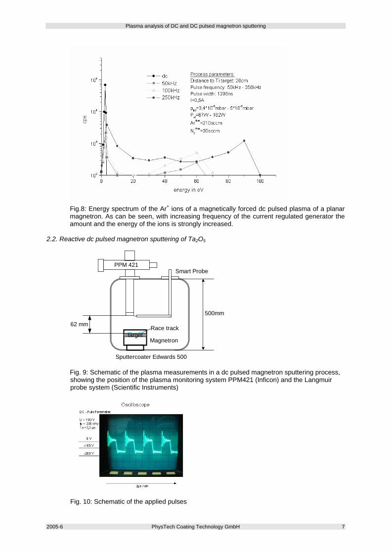
Fig.8: Energy spectrum of the Ar+ ions of a magnetically forced dc pulsed plasma of a planar magnetron. As can be seen, with increasing frequency of the current regulated generator the amount and the energy of the ions is strongly increased.
2.2. Reactive dc pulsed magnetron sputtering of Ta2O5
PPM 421 Smart Probe
Magnetron target
Race track
Sputtercoater Edwards 500
62 mm
500mm
Fig. 9: Schematic of the plasma measurements in a dc pulsed magnetron sputtering process, showing the position of the plasma monitoring system PPM421 (Inficon) and the Langmuir probe system (Scientific Instruments)
Fig. 10: Schematic of the applied pulses
Plasma analysis of DC and DC pulsed magnetron sputtering
8 PhysTech Coating Technology GmbH 2005-6
0 50 100 150 200
103
104
105
106
350kHz
100kHzDC
ta2o5_0_40_frequenz07/2004:Strauss/Schlichtherle
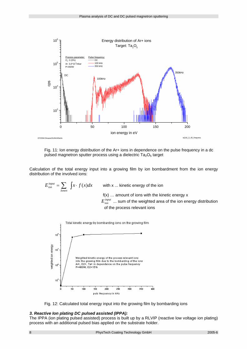
Process parameter:O2: 0 (0%)Ar: 3,0*10-3mbarP=450W
Energy distribution of Ar+ ionsTarget: Ta2O5
Pulse frequency: DC 100 kHz 350 kHz
cps
ion energy in eV
Fig. 11: Ion energy distribution of the Ar+ ions in dependence on the pulse frequency in a dc pulsed magnetron sputter process using a dielectric Ta2O5 target
Calculation of the total energy input into a growing film by ion bombardment from the ion energy distribution of the involved ions:
∫∑ ⋅= dxxfxEIonen
inpution )( with x ... kinetic energy of the ion
f(x) … amount of ions with the kinetic energy x inputionE ... sum of the weighted area of the ion energy distribution of the process relevant ions
Fig. 12: Calculated total energy input into the growing film by bombarding ions
3. Reactive Ion plating DC pulsed assisted (IPPA): The IPPA (ion plating pulsed assisted) process is built up by a RLVIP (reactive low voltage ion plating) process with an additional pulsed bias applied on the substrate holder.
Plasma analysis of DC and DC pulsed magnetron sputtering
2005-6 PhysTech Coating Technology GmbH 9
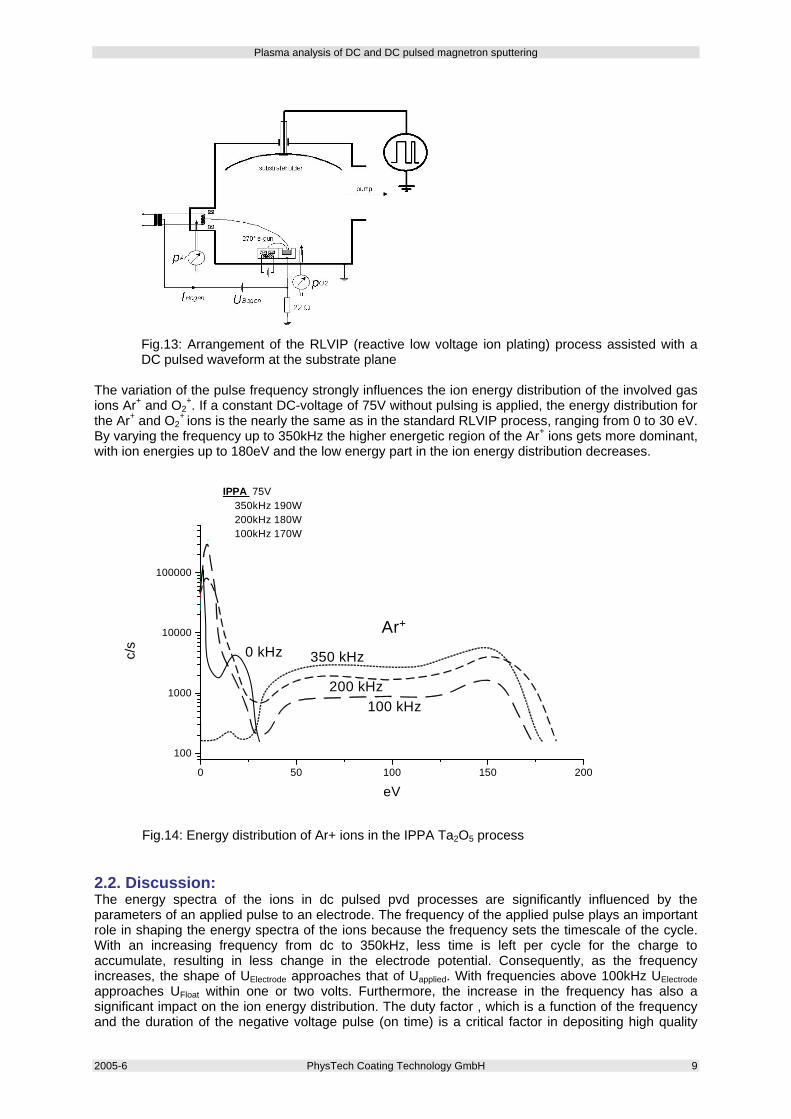
Fig.13: Arrangement of the RLVIP (reactive low voltage ion plating) process assisted with a DC pulsed waveform at the substrate plane
The variation of the pulse frequency strongly influences the ion energy distribution of the involved gas ions Ar+ and O2
+. If a constant DC-voltage of 75V without pulsing is applied, the energy distribution for the Ar+ and O2
+ ions is the nearly the same as in the standard RLVIP process, ranging from 0 to 30 eV. By varying the frequency up to 350kHz the higher energetic region of the Ar+ ions gets more dominant, with ion energies up to 180eV and the low energy part in the ion energy distribution decreases.
0 50 100 150 200
100
1000
10000
100000
IPPA 75V 350kHz 190W 200kHz 180W 100kHz 170W 0kHz 125W
Ar+
350kHz 200Khz 100kHz 0kHz
c/s
eV
0 kHz
100 kHz200 kHz
350 kHz
Ar+
Fig.14: Energy distribution of Ar+ ions in the IPPA Ta2O5 process
2.2. Discussion: The energy spectra of the ions in dc pulsed pvd processes are significantly influenced by the parameters of an applied pulse to an electrode. The frequency of the applied pulse plays an important role in shaping the energy spectra of the ions because the frequency sets the timescale of the cycle. With an increasing frequency from dc to 350kHz, less time is left per cycle for the charge to accumulate, resulting in less change in the electrode potential. Consequently, as the frequency increases, the shape of UElectrode approaches that of Uapplied. With frequencies above 100kHz UElectrode approaches UFloat within one or two volts. Furthermore, the increase in the frequency has also a significant impact on the ion energy distribution. The duty factor , which is a function of the frequency and the duration of the negative voltage pulse (on time) is a critical factor in depositing high quality
Plasma analysis of DC and DC pulsed magnetron sputtering
10 PhysTech Coating Technology GmbH 2005-6
films at frequencies between 5 and 100kHz, because there is a strong effect of the duty factor on the energy distribution of the process ions [1, 7]. In dc magnetron sputter configuration the kinetic energies of the ions are in the range from 0 to 15eV, depending on the process parameters and configuration. In this case, no high energy peak can be seen in the ion energy distribution [8]. Applying a pulsed voltage to the electrode (target), the energy spectrum is getting bimodal in nature, with a sharp low energy peak and an additional higher energy peak. With increasing frequency, the lower energy peak decreases in amplitude and the higher energy peak increases in amplitude (e.g. Fig 8, 11 and 14). The increased amplitude of the high energy peak, with increasing frequency, results from the relative increase in the percentage of the total ion flux that arrives to the electrode with a higher energy in the range of Ei +/- ΔE. Pulsing the target is a technique that allows the modification of film surfaces by bombardment of ions with higher kinetic energy than those observed in dc sputtering discharges. From the ion energy distributions shown in Fig.8, 11 and 14 it is apparent that the ions at higher energies make up a significant fraction of the total ion flux at the substrate, which leads to a significant increase in the total ion energy input to a growing film by the bombarding ions. With increasing frequency, for a given duty, the total ion energy by bombarding ions on a growing film is seen to approach some asymptotic value, see Fig.12. The average energy of the high energy peak is seen to approach also an asymptotic value at higher frequencies. Another factor which has an influence on the shape of the applied electrode voltage and the ion energy spectra is the duty of the pulse, or the fraction of the total period Uapplied is set to Uhigh. While the frequency of the pulse determine the total time of the cycle, the duty establishes the time within the cycle the pulse is set to Uhigh and Ulow. In addition to increasing the frequency, the duty can be increased, increasing the time to allow higher energy ion extraction and to reduce lower energy ion extraction, so with increasing duty more and more ions are shifted into the higher energy regime. As a conclusion it can be mentioned, that the dependence of the ion energy distribution on the frequency and the duty of the applied pulse leads to the possibility to control the kinetic energy of the process relevant ions and further to control the energy input into the growing film by ion bombardment by varying the frequency or the pulse duty. On the other hand, film property modifications by ion bombardment are mainly caused by momentum transfer from the ions to the film atoms. The collisional effects due to the bombardment of energetic particles during film deposition can produce a large variety of effects in the growing film [5, 6, 8]. These effects can appear as structural modifications to the crystal structure and orientation of the film, changes in the average grain size of the film, modification of the film stress, incorporation of inert gases, modification on the lattice constants and numerous other film property changes. Chemically, the film can be made purer, with better adhesion to the substrate, and the relative stoichiometry of the film can be altered over a broad range. These changes can subsequently affect such film properties like the film density, the refractive index, the optical absorption, mechanical stress, adhesion, electrical resistance, the stability on air and surface topography. As a consequence dc pulsed configurations give the ability to control various mechanical, optical and electrical film properties by controlling the parameter pulse frequency and pulse duty. 3. References: [1] Edward V. Barnat, Toh-Ming Lu, Pulsed and Pulsed Bias Sputtering, Kluwer Academic Publishers, (2003) [2] H. Bartzsch, P. Frach, K. Goedicke, Anode effects on energetic particle bombardment of the substrate in pulsed magnetron sputtering, Suf. Coat. Technol. 132, 244-250, (2000) [3] B. Chapman, Glow Discharge Processes, John Wiley&Sons, New York, (1980) [4] G.N. Strauss, H.K. Pulker, Plasma diagnostic of ion and plasma PVD processes, Thin Solid Films 442, 66-73, (2003) [5] C. Engström, et.al., Vacuum 56, 107, (2000) [6] H. Kersten, et.al., On the energy influx to the substrate during sputter deposition of thin aluminium films, Thin Solid Films 332, 282-289, (1998) [7] P.J. Kelly, P.S. Henderson, R.D. Arnell, G.A. Roche, D. Carter, j.Vac.Sci.Technol. A18(6), 2890-2896, (2000) [8] C. Muratore, J.J. Moore, J.A. Rees, Electrostatic quadrupol plasma mass spectrometer and Langmuir probe measurements of mid-frequency pulsed DC magnetron discharges, Surface and Coatings Technology, (2002) [9] P.J. Kelly, et.al, Substrate effects during mid-frequency pulsed dc biasing, Surface and Coatings Technology 142-144, 635-641, (2001)