Physics II - Wydział Fizyki Politechniki Warszawskiejdanielb/?download=PhysicsII_part2_EM...These...
123
Electromagnetic waves Daniel Budaszewski Ph.D. Eng. Physics II
Transcript of Physics II - Wydział Fizyki Politechniki Warszawskiejdanielb/?download=PhysicsII_part2_EM...These...
Electromagnetic waves
Daniel Budaszewski Ph.D. Eng.
Physics II
*
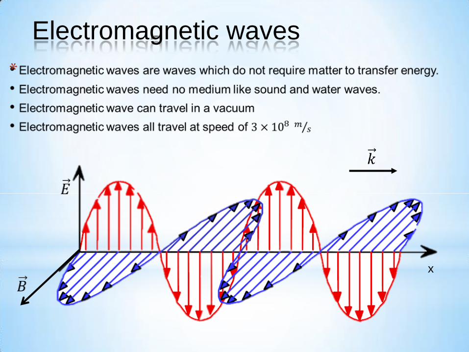
Electromagnetic waves
x
3
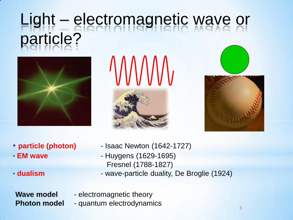
• particle (photon) - Isaac Newton (1642-1727)
• EM wave - Huygens (1629-1695)
Fresnel (1788-1827)
• dualism - wave-particle duality, De Broglie (1924)
Wave model - electromagnetic theory
Photon model - quantum electrodynamics
Light – electromagnetic wave or
particle?
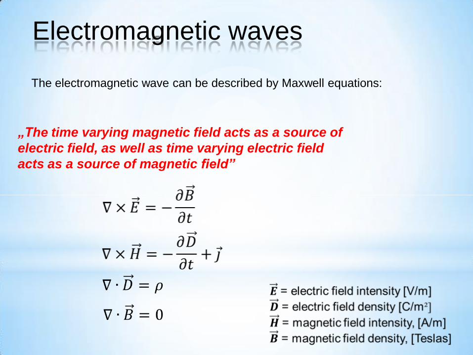
The electromagnetic wave can be described by Maxwell equations:
„The time varying magnetic field acts as a source of
electric field, as well as time varying electric field
acts as a source of magnetic field”
Electromagnetic waves
Electromagnetic waves
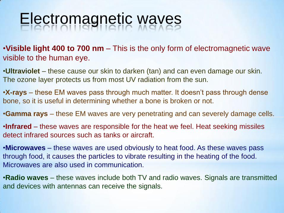
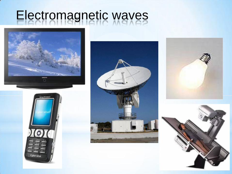
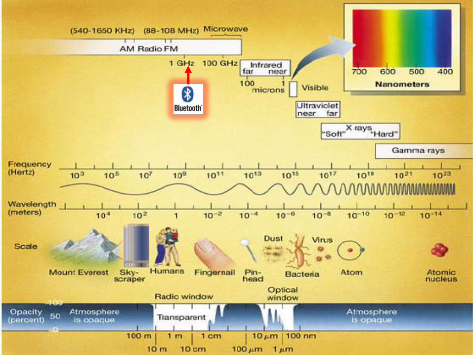
•Visible light 400 to 700 nm – This is the only form of electromagnetic wave
visible to the human eye.
•Ultraviolet – these cause our skin to darken (tan) and can even damage our skin.
The ozone layer protects us from most UV radiation from the sun.
•X-rays – these EM waves pass through much matter. It doesn’t pass through dense
bone, so it is useful in determining whether a bone is broken or not.
•Gamma rays – these EM waves are very penetrating and can severely damage cells.
•Infrared – these waves are responsible for the heat we feel. Heat seeking missiles
detect infrared sources such as tanks or aircraft.
•Microwaves – these waves are used obviously to heat food. As these waves pass
through food, it causes the particles to vibrate resulting in the heating of the food.
Microwaves are also used in communication.
•Radio waves – these waves include both TV and radio waves. Signals are transmitted
and devices with antennas can receive the signals.
Electromagnetic waves
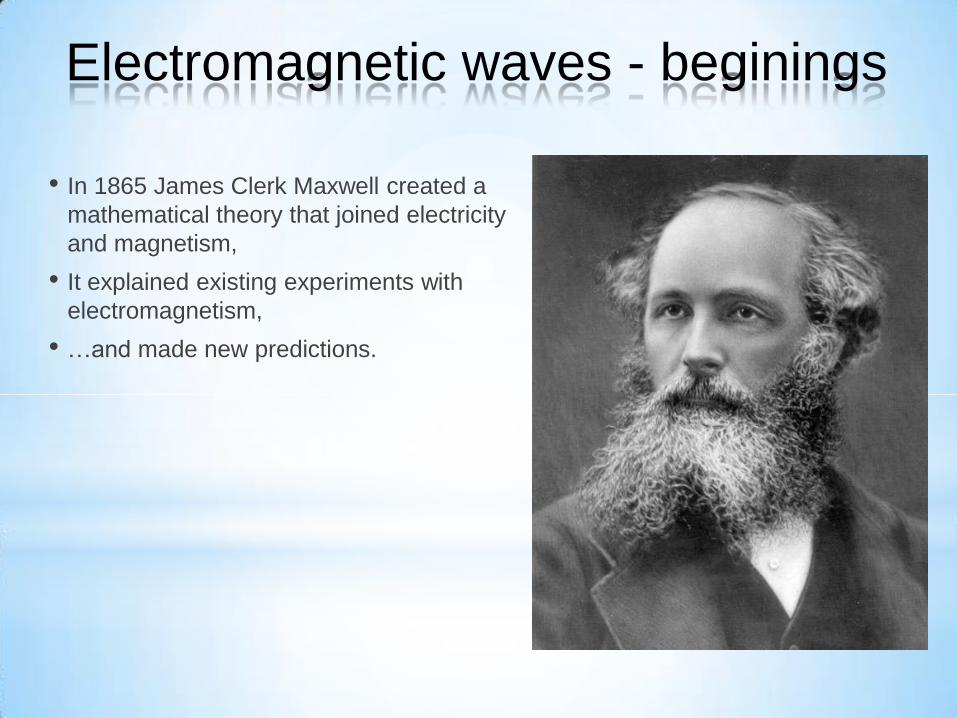
• In 1865 James Clerk Maxwell created a
mathematical theory that joined electricity
and magnetism,
• It explained existing experiments with
electromagnetism,
• …and made new predictions.
Electromagnetic waves - beginings
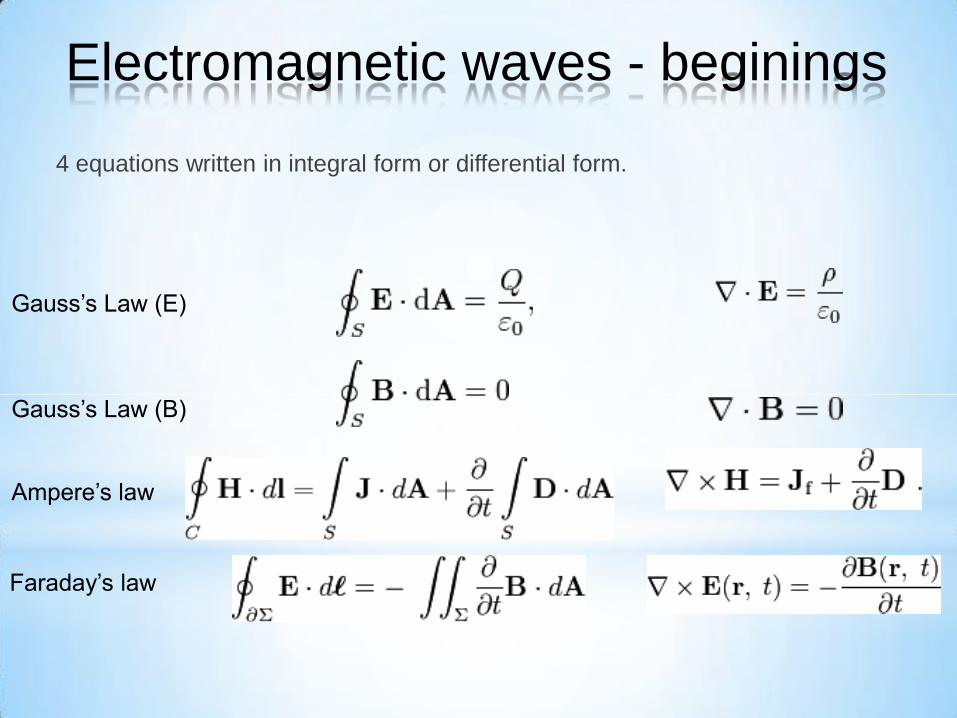
4 equations written in integral form or differential form.
Gauss’s Law (E)
Gauss’s Law (B)
Ampere’s law
Faraday’s law
Electromagnetic waves - beginings
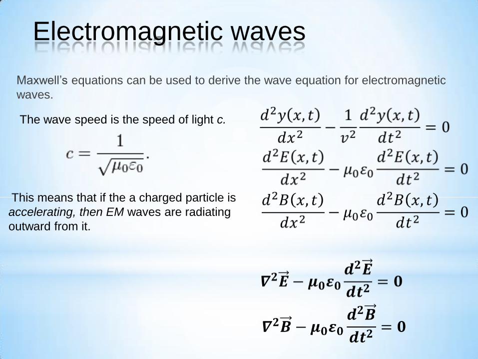
Maxwell’s equations can be used to derive the wave equation for electromagnetic
waves.
The wave speed is the speed of light c.
This means that if the a charged particle is
accelerating, then EM waves are radiating
outward from it.
Electromagnetic waves
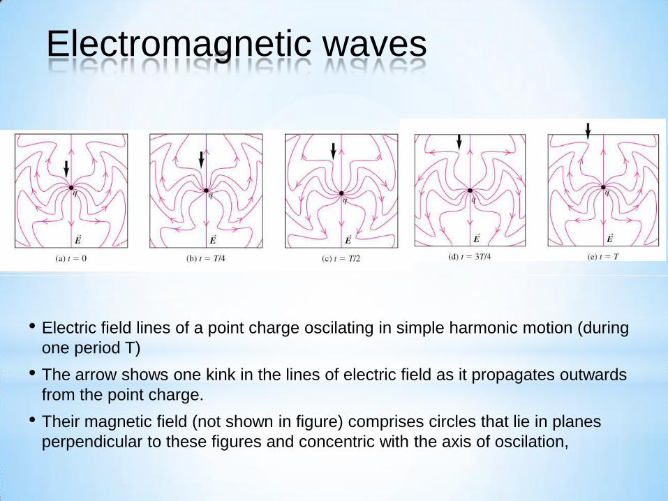
• Electric field lines of a point charge oscilating in simple harmonic motion (during
one period T)
• The arrow shows one kink in the lines of electric field as it propagates outwards
from the point charge.
• Their magnetic field (not shown in figure) comprises circles that lie in planes
perpendicular to these figures and concentric with the axis of oscilation,
Electromagnetic waves
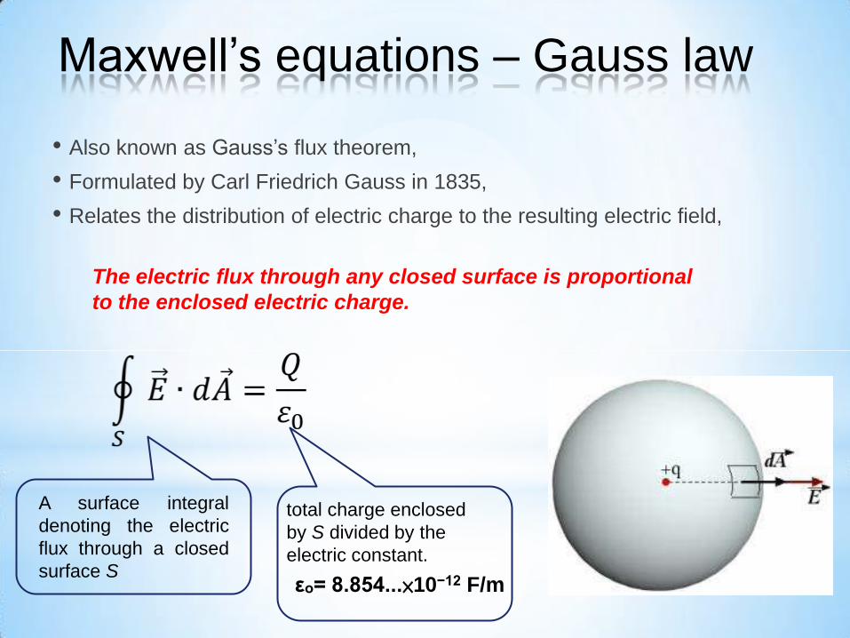
• Also known as Gauss’s flux theorem,
• Formulated by Carl Friedrich Gauss in 1835,
• Relates the distribution of electric charge to the resulting electric field,
The electric flux through any closed surface is proportional
to the enclosed electric charge.
A surface integral
denoting the electric
flux through a closed
surface S
total charge enclosed
by S divided by the
electric constant.
εₒ= 8.854...×10−12 F/m
Maxwell’s equations – Gauss law
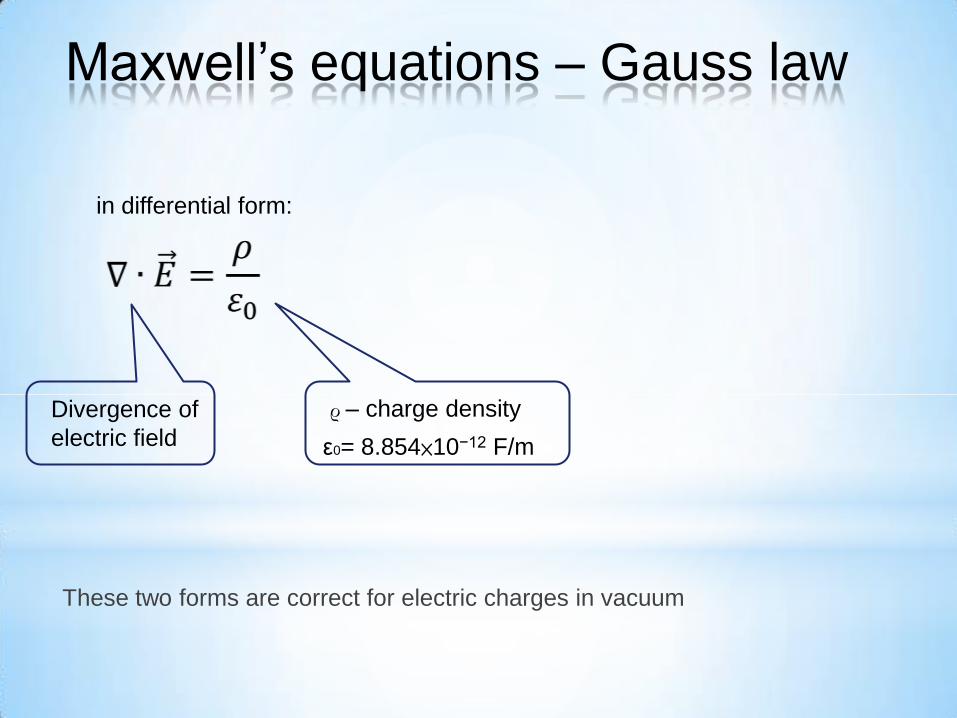
in differential form:
Divergence of
electric field
ρ – charge density
ε0= 8.854×10⁻¹² F/m
These two forms are correct for electric charges in vacuum
Maxwell’s equations – Gauss law
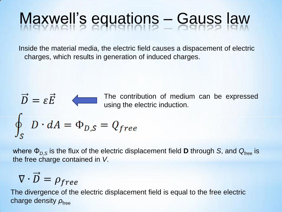
The contribution of medium can be expressed
using the electric induction.
Inside the material media, the electric field causes a dispacement of electric
charges, which results in generation of induced charges.
where ΦD,S is the flux of the electric displacement field D through S, and Qfree is
the free charge contained in V.
The divergence of the electric displacement field is equal to the free electric
charge density ρfree
Maxwell’s equations – Gauss law
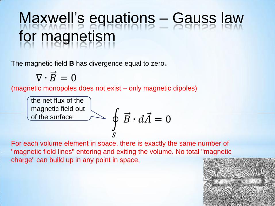
The magnetic field B has divergence equal to zero.
(magnetic monopoles does not exist – only magnetic dipoles)
For each volume element in space, there is exactly the same number of
"magnetic field lines" entering and exiting the volume. No total "magnetic
charge" can build up in any point in space.
the net flux of the
magnetic field out
of the surface
Maxwell’s equations – Gauss law
for magnetism
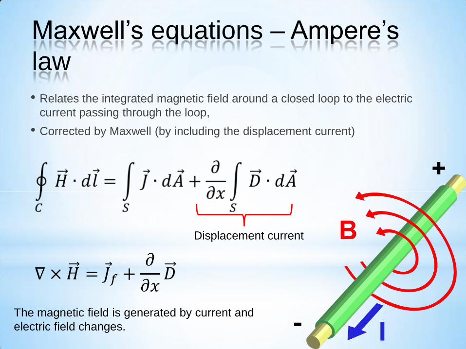
• Relates the integrated magnetic field around a closed loop to the electric
current passing through the loop,
• Corrected by Maxwell (by including the displacement current)
Displacement current
The magnetic field is generated by current and
electric field changes.
Maxwell’s equations – Ampere’s
law
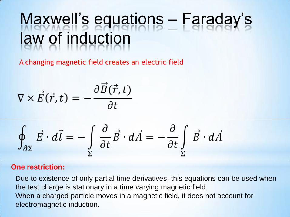
A changing magnetic field creates an electric field
Due to existence of only partial time derivatives, this equations can be used when
the test charge is stationary in a time varying magnetic field.
When a charged particle moves in a magnetic field, it does not account for
electromagnetic induction.
One restriction:
Maxwell’s equations – Faraday’s
law of induction
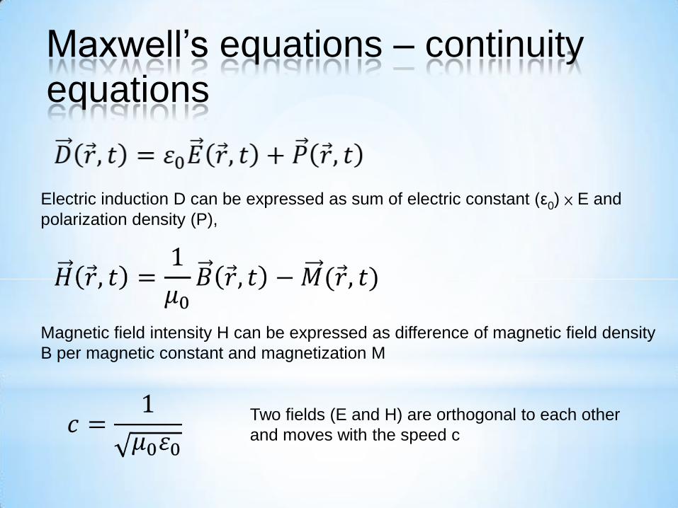
Electric induction D can be expressed as sum of electric constant (ε0) × E and
polarization density (P),
Magnetic field intensity H can be expressed as difference of magnetic field density
B per magnetic constant and magnetization M
Two fields (E and H) are orthogonal to each other
and moves with the speed c
Maxwell’s equations – continuity
equations
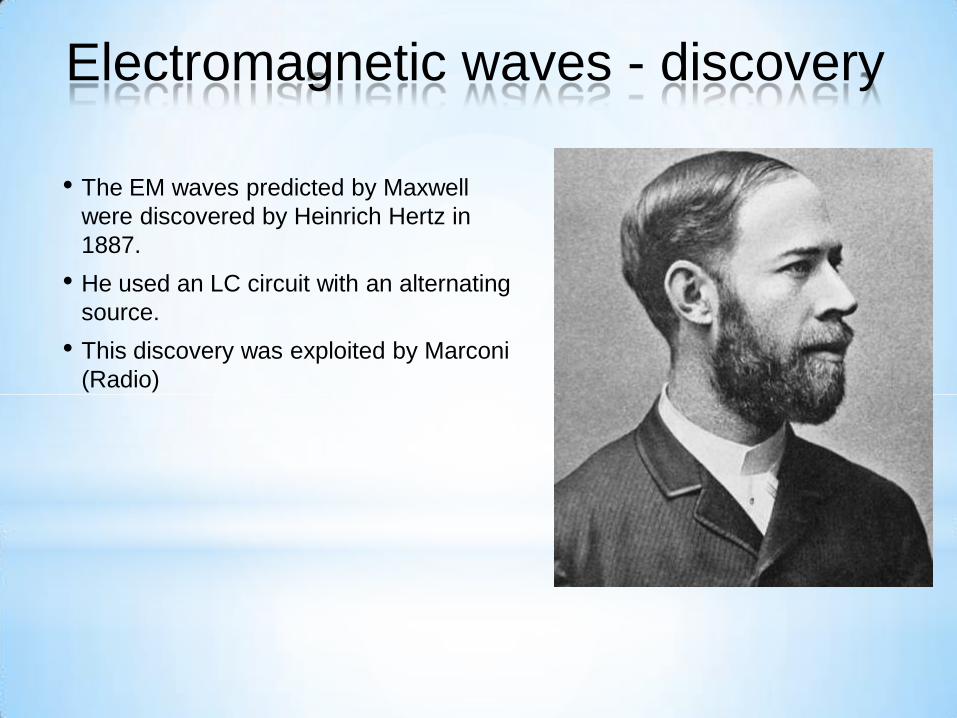
• The EM waves predicted by Maxwell
were discovered by Heinrich Hertz in
1887.
• He used an LC circuit with an alternating
source.
• This discovery was exploited by Marconi
(Radio)
Electromagnetic waves - discovery
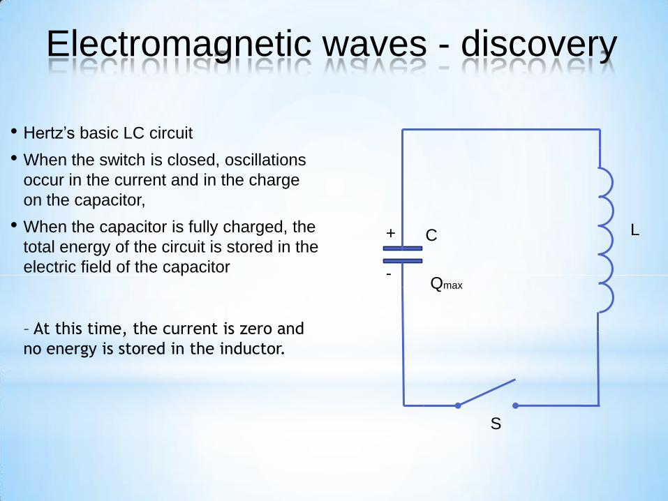
• Hertz’s basic LC circuit
• When the switch is closed, oscillations
occur in the current and in the charge
on the capacitor,
• When the capacitor is fully charged, the
total energy of the circuit is stored in the
electric field of the capacitor
– At this time, the current is zero and
no energy is stored in the inductor.
Electromagnetic waves - discovery
S
C L
Qmax
+
-

• As the capacitor discharges, the energy stored in the electric field decreases ,
• At the same time, the current increases and the energy stored in the magnetic
field increases,
• When the capacitor is fully discharged, there is no energy stored in its electric
field,
• The current is at a maximum and all the energy is stored in the magnetic field
in the inductor,
• The process repeats in the opposite direction,
• There is a continuous transfer of energy between the inductor and the
capacitor.
Electromagnetic waves - discovery
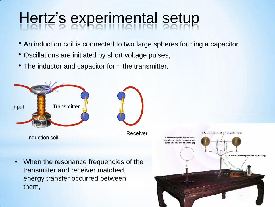
• An induction coil is connected to two large spheres forming a capacitor,
• Oscillations are initiated by short voltage pulses,
• The inductor and capacitor form the transmitter,
Hertz’s experimental setup
Input
Induction coil
Transmitter
Receiver
• When the resonance frequencies of the
transmitter and receiver matched,
energy transfer occurred between
them,
• Hertz hypothesized the energy transfer was in the form of waves
• These are now known to be electromagnetic waves
• Hertz confirmed Maxwell’s theory by showing the waves existed and had all
the properties of light waves
• They had different frequencies and wavelengths
• Hertz measured the speed of the waves from the transmitter
• He used the waves to form an interference pattern and calculated the wavelength,
From v = f λ, v was found (very close to speed of light)
• This provided evidence in support of Maxwell’s theory
Hertz’s conclusions
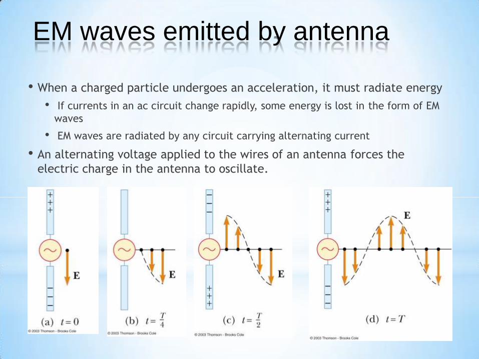
• When a charged particle undergoes an acceleration, it must radiate energy
• If currents in an ac circuit change rapidly, some energy is lost in the form of EM
waves
• EM waves are radiated by any circuit carrying alternating current
• An alternating voltage applied to the wires of an antenna forces the
electric charge in the antenna to oscillate.
EM waves emitted by antenna
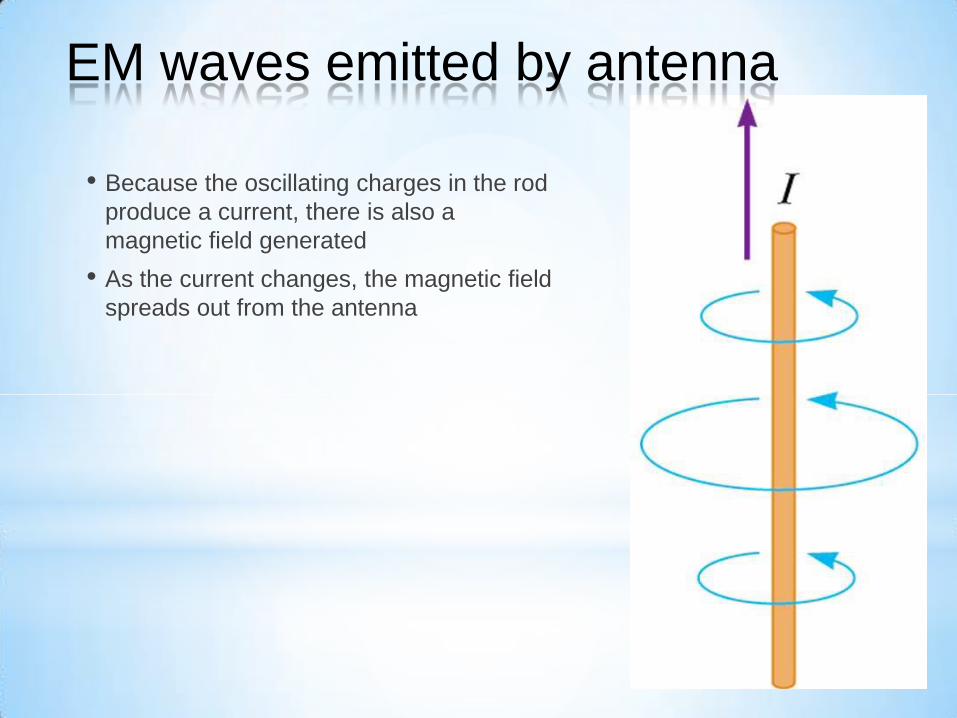
• Because the oscillating charges in the rod
produce a current, there is also a
magnetic field generated
• As the current changes, the magnetic field
spreads out from the antenna
EM waves emitted by antenna
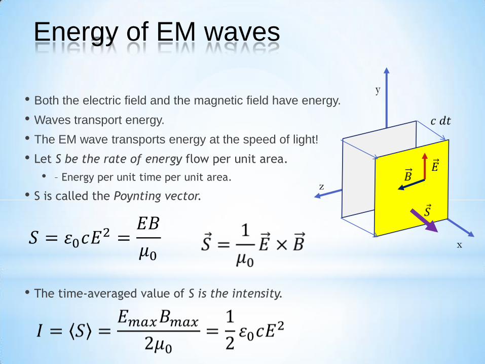
• Both the electric field and the magnetic field have energy.
• Waves transport energy.
• The EM wave transports energy at the speed of light!
• Let S be the rate of energy flow per unit area.
• – Energy per unit time per unit area.
• S is called the Poynting vector.
• The time-averaged value of S is the intensity.
Energy of EM waves
x
y
z
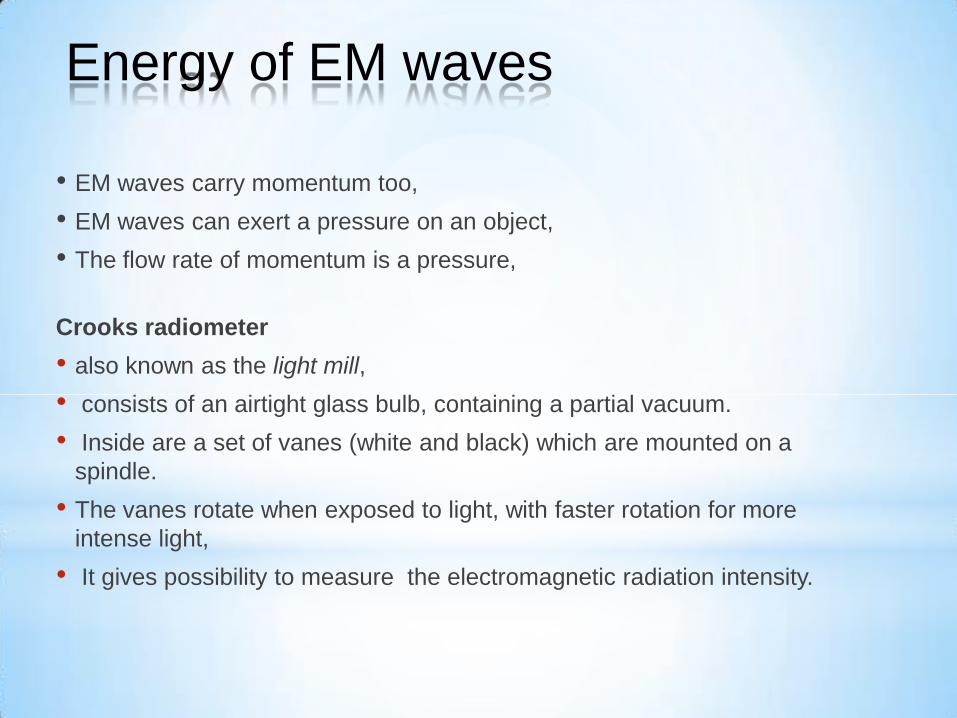
• EM waves carry momentum too,
• EM waves can exert a pressure on an object,
• The flow rate of momentum is a pressure,
Crooks radiometer
• also known as the light mill,
• consists of an airtight glass bulb, containing a partial vacuum.
• Inside are a set of vanes (white and black) which are mounted on a
spindle.
• The vanes rotate when exposed to light, with faster rotation for more
intense light,
• It gives possibility to measure the electromagnetic radiation intensity.
Energy of EM waves

STOP:
• The idea of work is not related to the pressure of light!
• The darker side of the vane is heated faster than the light one,
• The pressure difference causes the vane to move cold (light) side forward.
Energy of EM waves
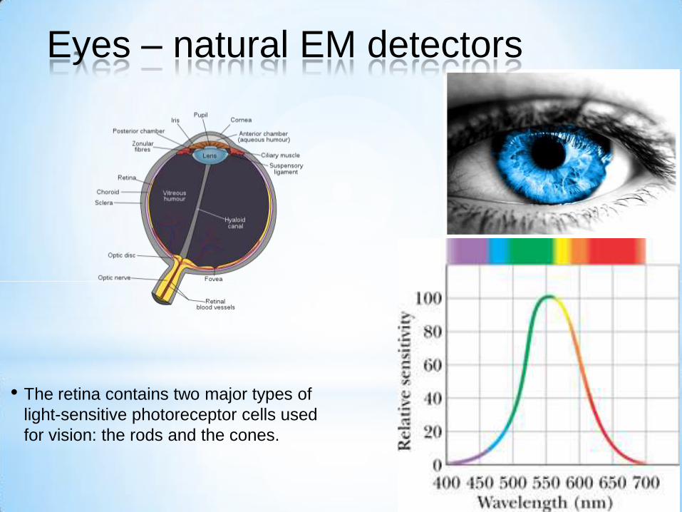
• The retina contains two major types of
light-sensitive photoreceptor cells used
for vision: the rods and the cones.
Eyes – natural EM detectors
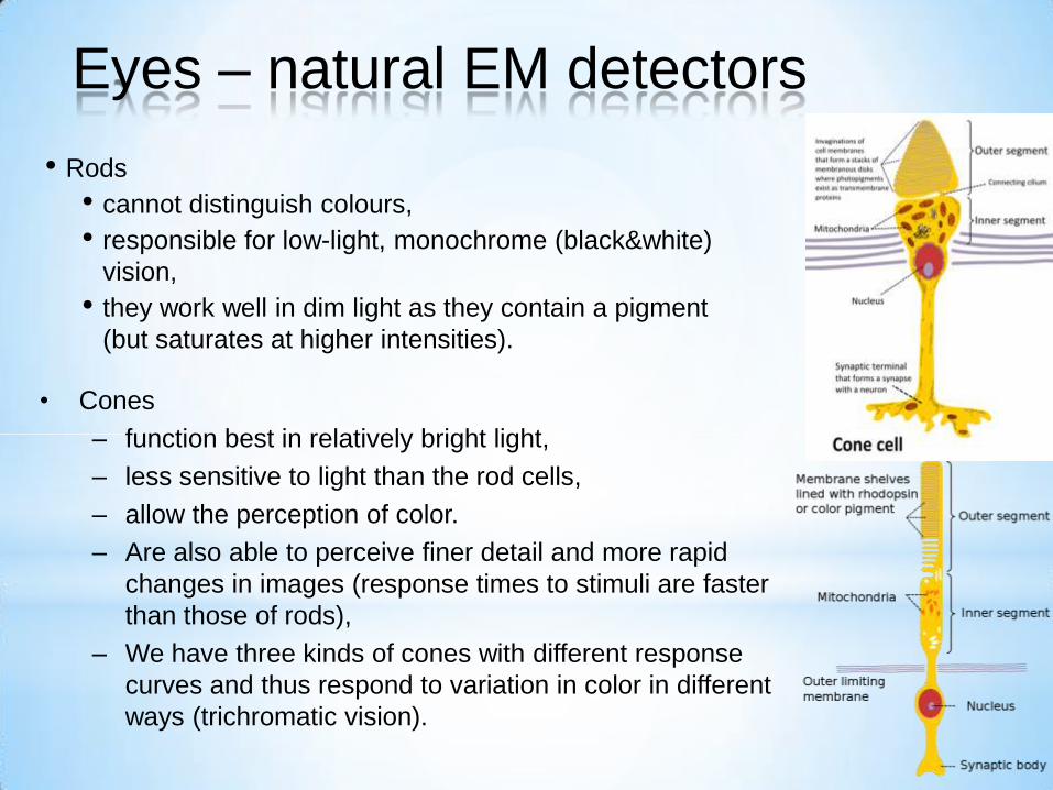
• Rods
• cannot distinguish colours,
• responsible for low-light, monochrome (black&white)
vision,
• they work well in dim light as they contain a pigment
(but saturates at higher intensities).
• Cones
– function best in relatively bright light,
– less sensitive to light than the rod cells,
– allow the perception of color.
– Are also able to perceive finer detail and more rapid
changes in images (response times to stimuli are faster
than those of rods),
– We have three kinds of cones with different response
curves and thus respond to variation in color in different
ways (trichromatic vision).
Eyes – natural EM detectors
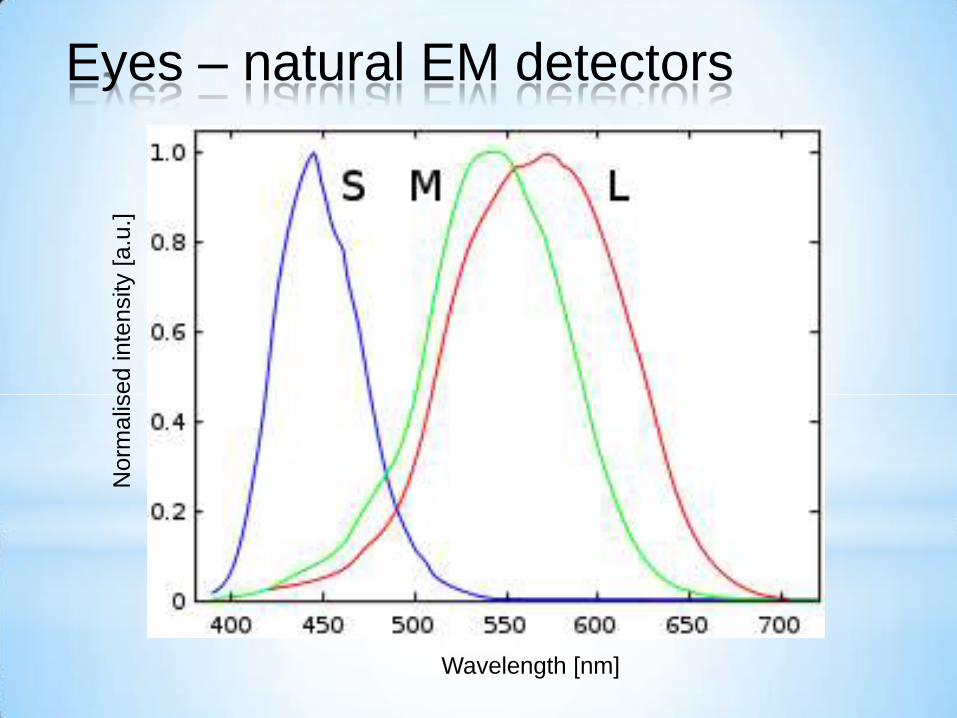
Wavelength [nm]
Norm
alis
ed
inte
nsity [
a.u
.]
Eyes – natural EM detectors
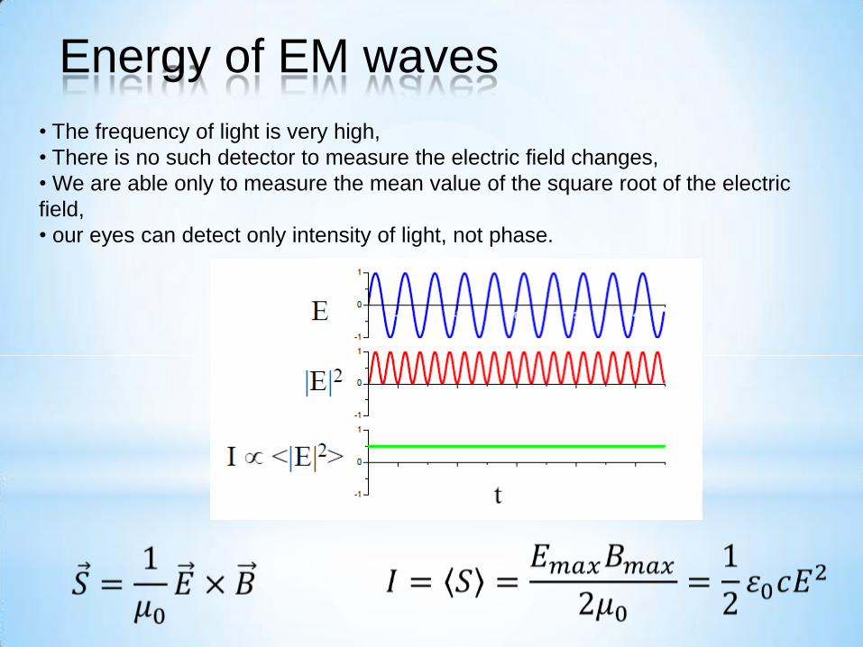
• The frequency of light is very high,
• There is no such detector to measure the electric field changes,
• We are able only to measure the mean value of the square root of the electric
field,
• our eyes can detect only intensity of light, not phase.
Energy of EM waves
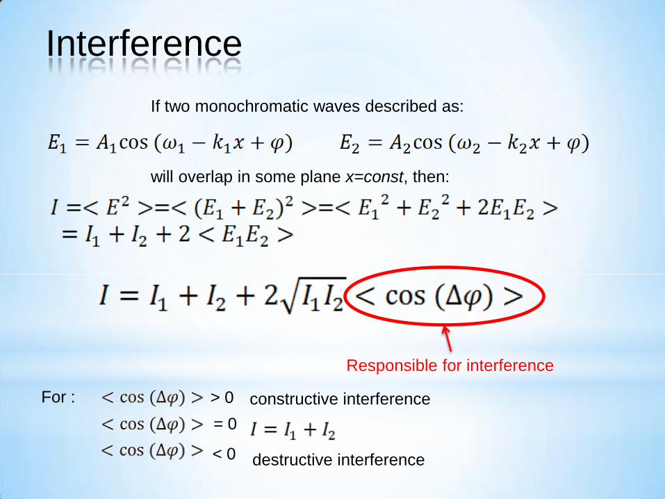
If two monochromatic waves described as:
will overlap in some plane x=const, then:
Responsible for interference
Interference
For : > 0 constructive interference
= 0
destructive interference < 0
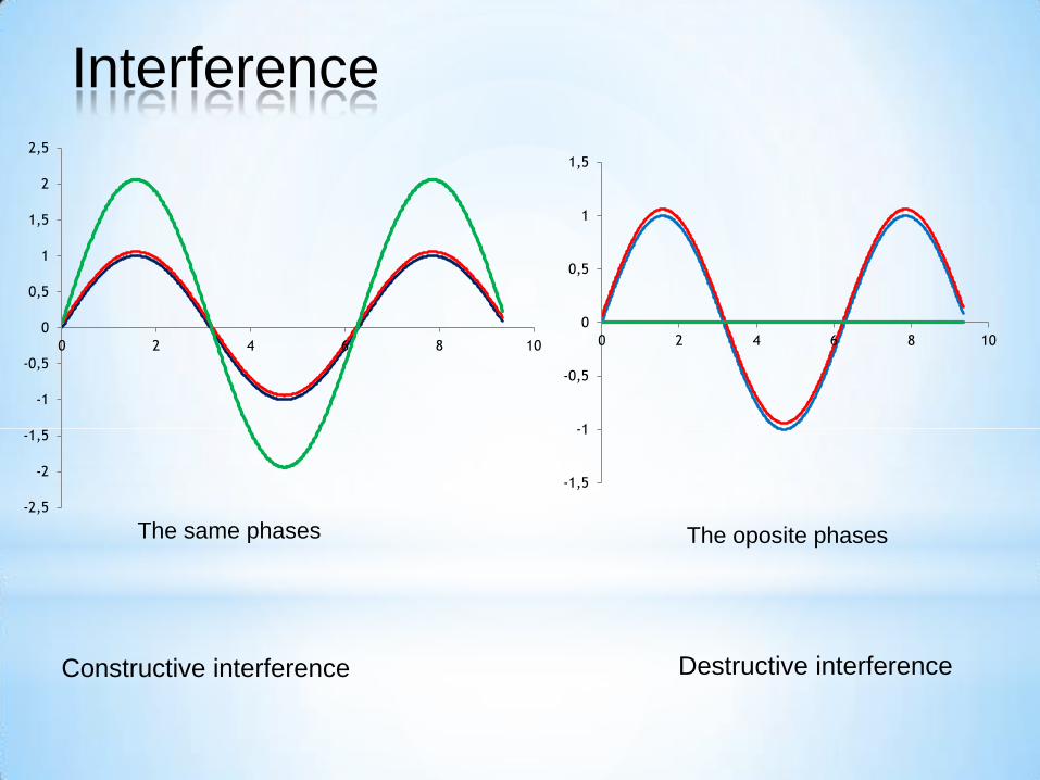
The same phases The oposite phases
Constructive interference Destructive interference
-2,5
-2
-1,5
-1
-0,5
0
0,5
1
1,5
2
2,5
0 2 4 6 8 10
-1,5
-1
-0,5
0
0,5
1
1,5
0 2 4 6 8 10
Interference
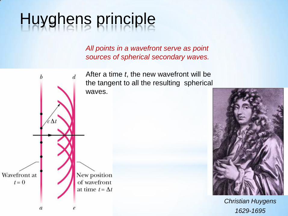
Christian Huygens
1629-1695
All points in a wavefront serve as point
sources of spherical secondary waves.
After a time t, the new wavefront will be
the tangent to all the resulting spherical
waves.
Huyghens principle
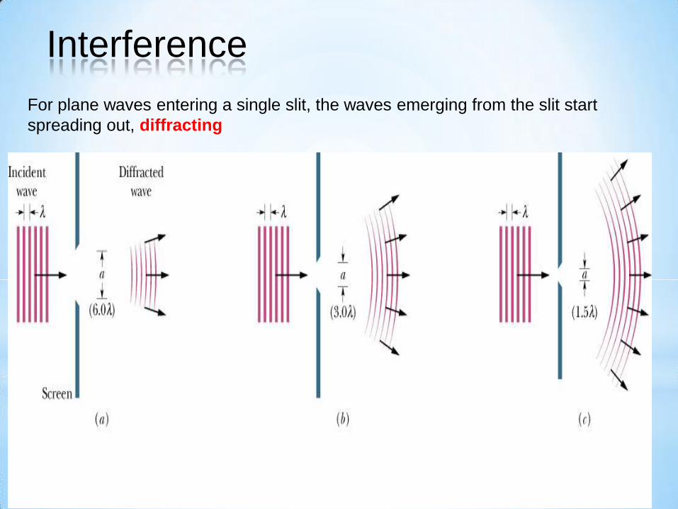
For plane waves entering a single slit, the waves emerging from the slit start
spreading out, diffracting
Interference
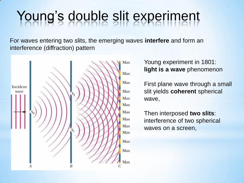
For waves entering two slits, the emerging waves interfere and form an
interference (diffraction) pattern
Young experiment in 1801:
light is a wave phenomenon
First plane wave through a small
slit yields coherent spherical
wave,
Then interposed two slits:
interference of two spherical
waves on a screen,
Young’s double slit experiment
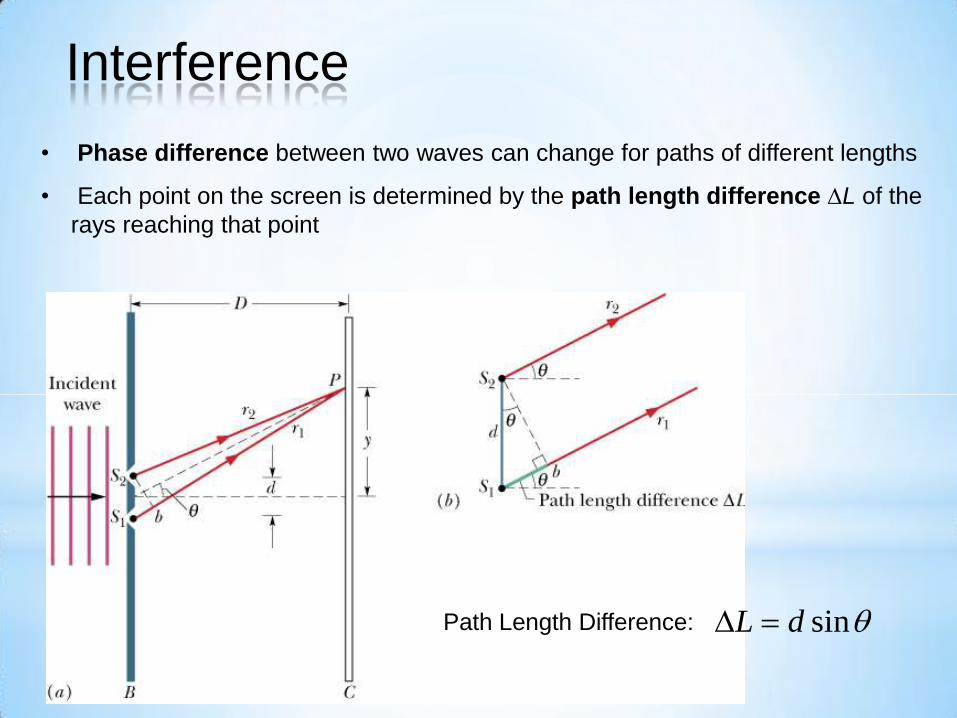
• Phase difference between two waves can change for paths of different lengths
• Each point on the screen is determined by the path length difference DL of the
rays reaching that point
Path Length Difference: sinL d D
Interference
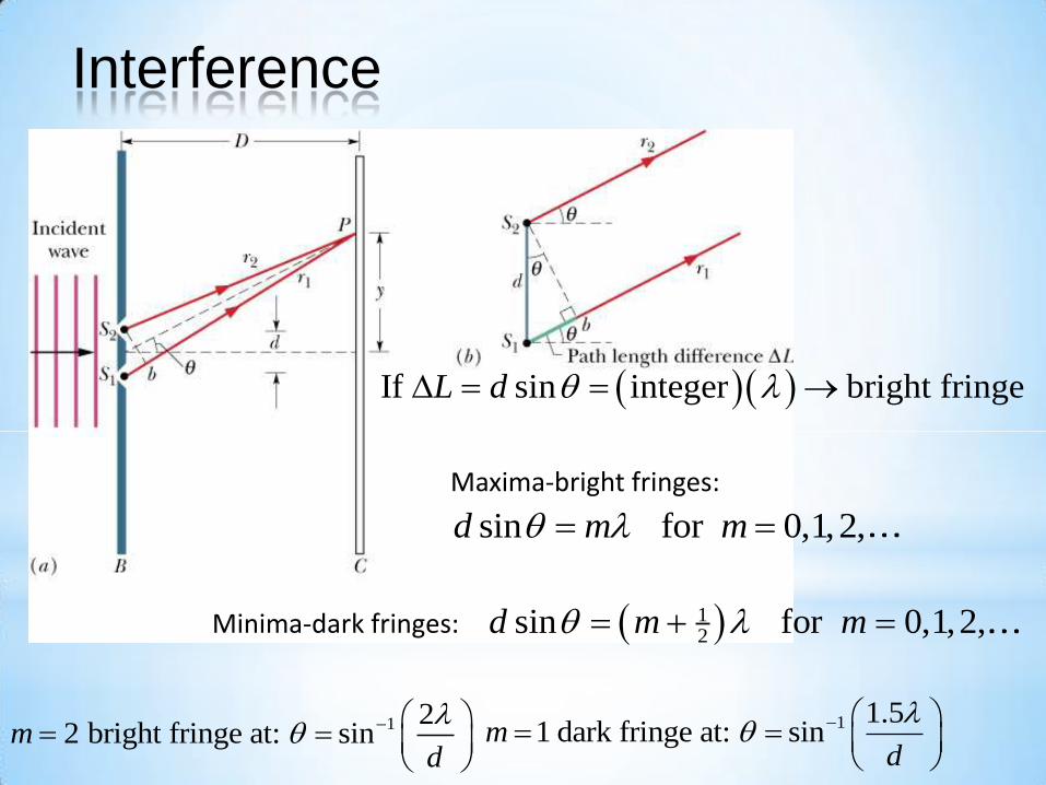
If sin integer bright fringeL d D
Maxima-bright fringes:
sin for 0,1,2,d m m
Minima-dark fringes: 12
sin for 0,1,2,d m m
1 1.51 dark fringe at: sinm
d
1 22 bright fringe at: sinm
d
Interference
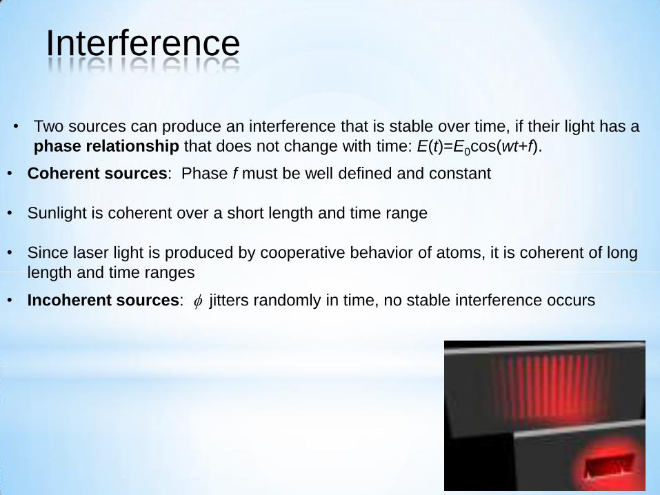
• Two sources can produce an interference that is stable over time, if their light has a
phase relationship that does not change with time: E(t)=E0cos(wt+f).
• Coherent sources: Phase f must be well defined and constant
• Sunlight is coherent over a short length and time range
• Since laser light is produced by cooperative behavior of atoms, it is coherent of long
length and time ranges
• Incoherent sources: f jitters randomly in time, no stable interference occurs
Interference
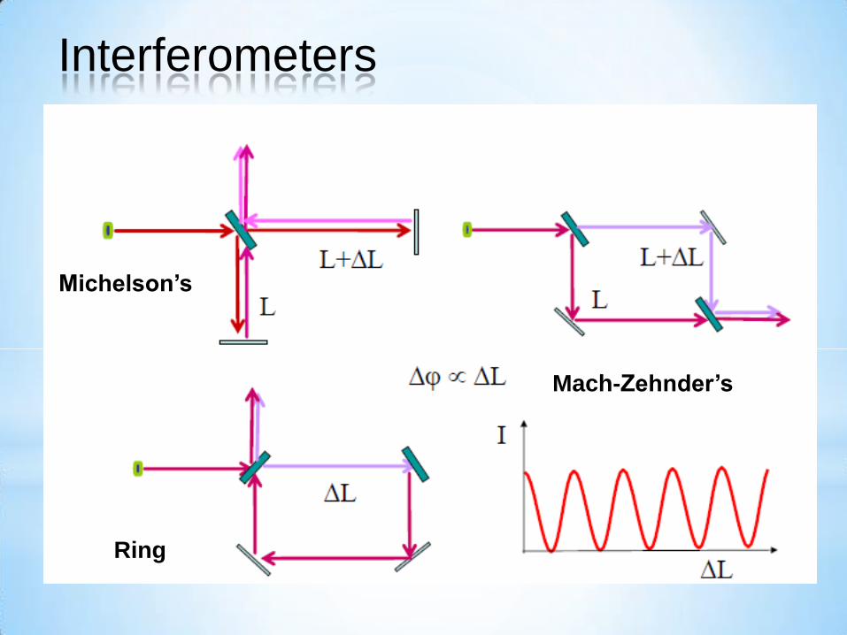
Michelson’s
Mach-Zehnder’s
Ring
Interferometers
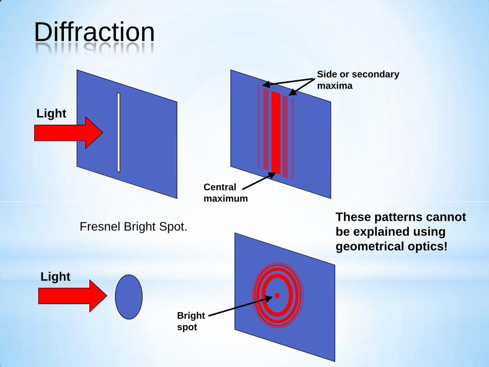
Central
maximum
Side or secondary
maxima
Light
Fresnel Bright Spot.
Bright
spot
Light
These patterns cannot
be explained using
geometrical optics!
Diffraction
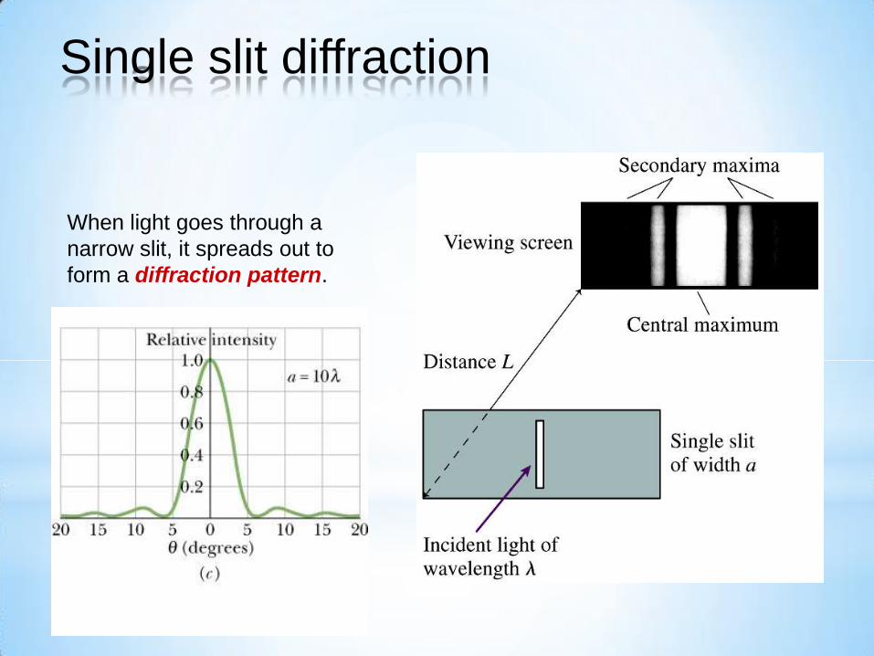
When light goes through a
narrow slit, it spreads out to
form a diffraction pattern.
Single slit diffraction
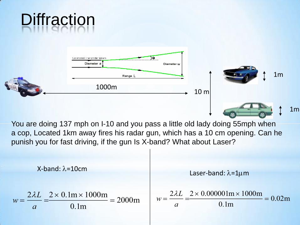
X-band: =10cm
You are doing 137 mph on I-10 and you pass a little old lady doing 55mph when
a cop, Located 1km away fires his radar gun, which has a 10 cm opening. Can he
punish you for fast driving, if the gun Is X-band? What about Laser?
1m
1m
10 m 1000m
w 2L
a2 0.1m 1000m
0.1m 2000m w
2L
a2 0.000001m 1000m
0.1m 0.02m
Laser-band: =1m
Diffraction

The Rayleigh Resolution Criterion
says that the minimum separation to
separate two objects is to have the
diffraction peak of one at the
diffraction minimum of the other, i.e.,
D 1.22 /D.
Example: The Hubble Space Telescope
has a mirror diameter of 4 m, leading to
excellent resolution of close-lying objects.
For light with wavelength of 500 nm, the
angular resolution of the Hubble is D = 1.53 x 10⁻⁷ radians.
Diffraction
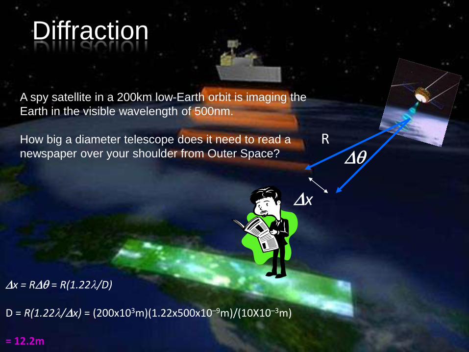
A spy satellite in a 200km low-Earth orbit is imaging the
Earth in the visible wavelength of 500nm.
How big a diameter telescope does it need to read a
newspaper over your shoulder from Outer Space?
Diffraction
R
Dx
D
Dx = RD = R(1.22/D) D = R(1.22/Dx) = (200x103m)(1.22x500x10–9m)/(10X10–3m) = 12.2m
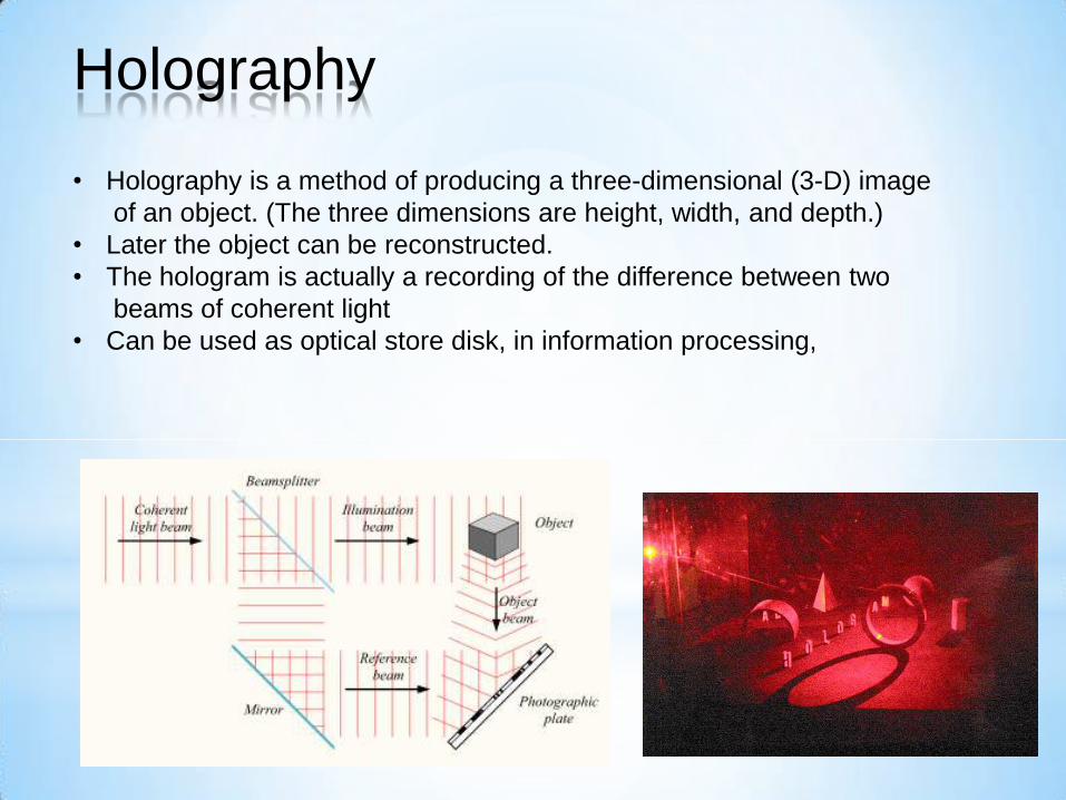
Holography
• Holography is a method of producing a three-dimensional (3-D) image
of an object. (The three dimensions are height, width, and depth.)
• Later the object can be reconstructed.
• The hologram is actually a recording of the difference between two
beams of coherent light
• Can be used as optical store disk, in information processing,

Conventional:
• 2-d version of a 3-d scene
• Photograph lacks depth perception or parallax
• Film sensitive only to radiant energy
• Phase relation (i.e. interference) are lost
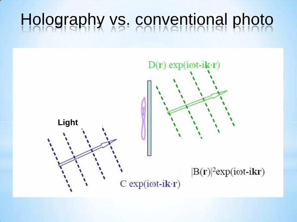
Holography vs. conventional photo
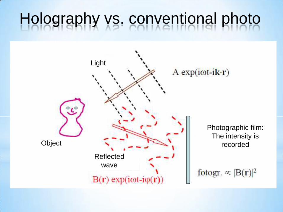
Light
Object
Reflected
wave
Photographic film:
The intensity is
recorded
Holography vs. conventional photo
Holography vs. conventional photo
Light
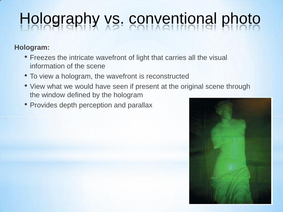
Hologram:
• Freezes the intricate wavefront of light that carries all the visual
information of the scene
• To view a hologram, the wavefront is reconstructed
• View what we would have seen if present at the original scene through
the window defined by the hologram
• Provides depth perception and parallax
Holography vs. conventional photo
• Converts phase information into amplitude information (in-phase -
maximum amplitude, out-of-phase – minimum amplitude)
• Interfere wavefront of light from a scene with a reference wave
• The hologram is a complex interference pattern of microscopically
spaced fringes
Holography vs. conventional photo
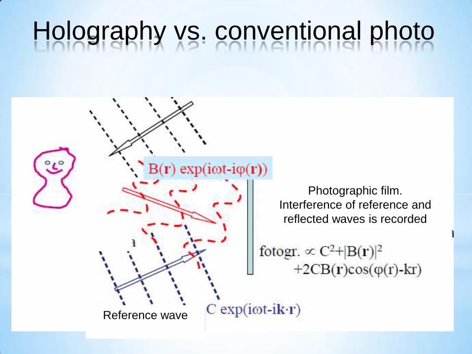
Reference wave
Photographic film.
Interference of reference and
reflected waves is recorded
Holography vs. conventional photo

• Film is developed,
• Hologram illuminated at same angle as reference beam during
original exposure to reveal holographic image,
Holography vs. conventional photo
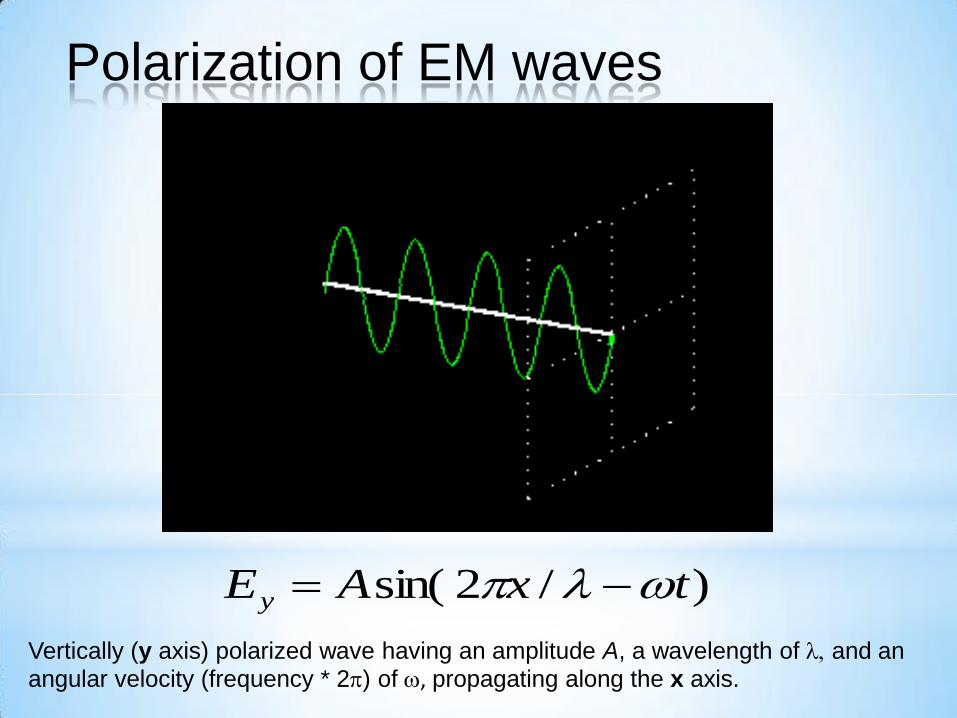
)/2sin( txAEy
Vertically (y axis) polarized wave having an amplitude A, a wavelength of and an
angular velocity (frequency * 2) of , propagating along the x axis.
Polarization of EM waves
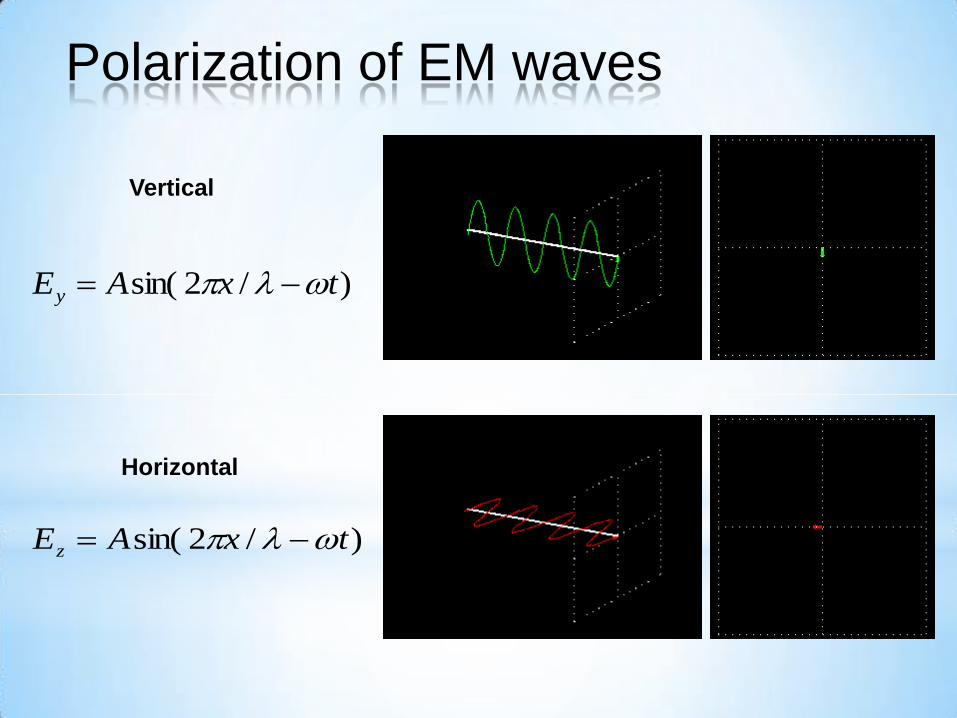
Vertical
Horizontal
)/2sin( txAEy
)/2sin( txAEz
Polarization of EM waves
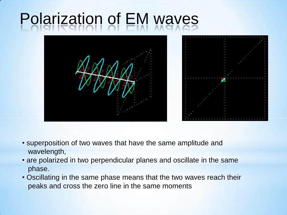
• superposition of two waves that have the same amplitude and
wavelength,
• are polarized in two perpendicular planes and oscillate in the same
phase.
• Oscillating in the same phase means that the two waves reach their
peaks and cross the zero line in the same moments
Polarization of EM waves
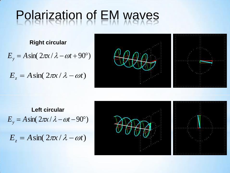
Right circular
Left circular
)90/2sin( txAEy
)/2sin( txAEz
)90/2sin( txAEy
)/2sin( txAEz
Polarization of EM waves
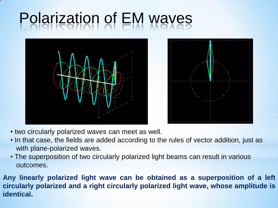
• two circularly polarized waves can meet as well.
• In that case, the fields are added according to the rules of vector addition, just as
with plane-polarized waves.
• The superposition of two circularly polarized light beams can result in various
outcomes.
Any linearly polarized light wave can be obtained as a superposition of a left
circularly polarized and a right circularly polarized light wave, whose amplitude is
identical.
Polarization of EM waves
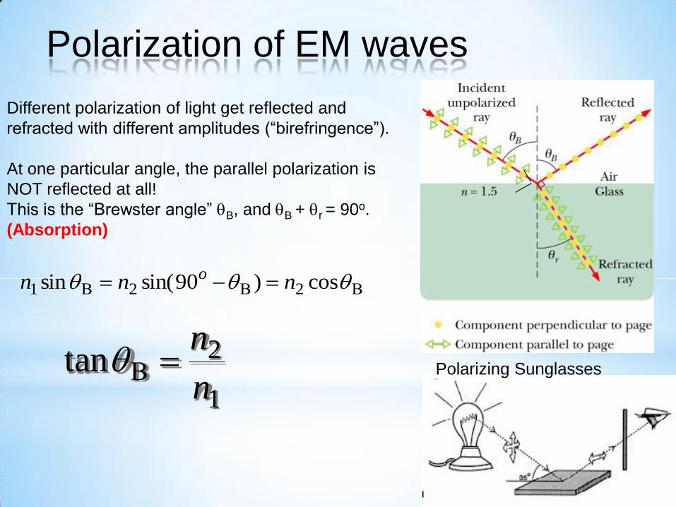
Different polarization of light get reflected and
refracted with different amplitudes (“birefringence”).
At one particular angle, the parallel polarization is
NOT reflected at all!
This is the “Brewster angle” B, and B + r = 90o.
(Absorption)
cos)90sin(sin 221 nnn o
1
2tann
n Polarizing Sunglasses
Polarization of EM waves
Polarization of EM waves

Polarization of EM waves
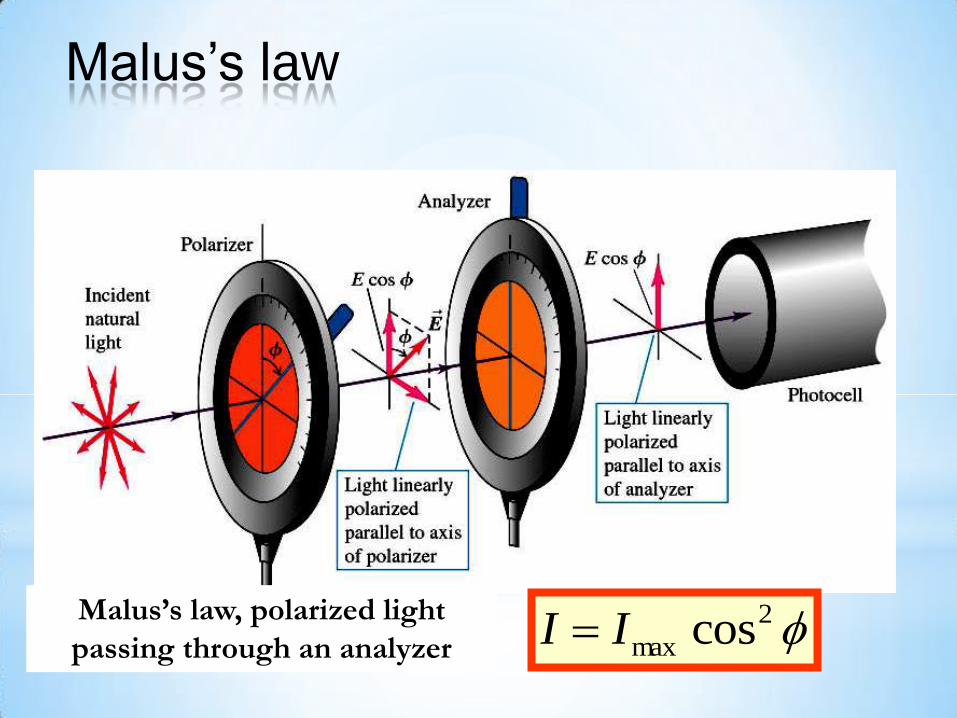
f2
max cosII Malus’s law, polarized light
passing through an analyzer
Malus’s law
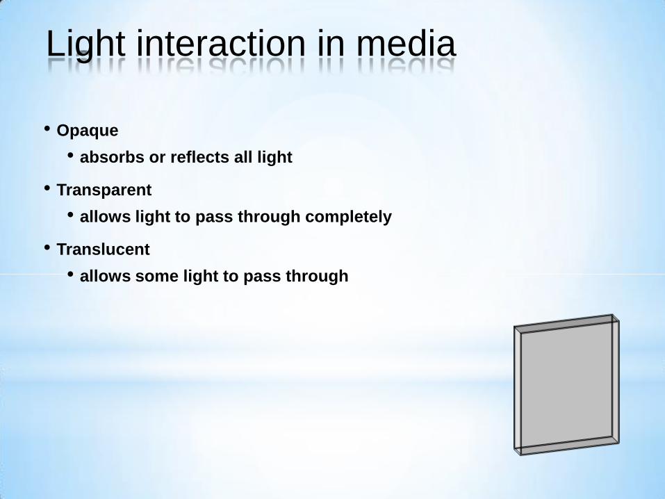
• Opaque
• absorbs or reflects all light
• Transparent
• allows light to pass through completely
• Translucent
• allows some light to pass through
Light interaction in media
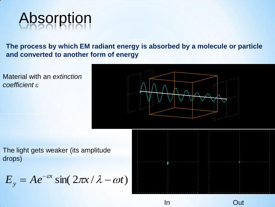
)/2sin( txAeE x
y
Material with an extinction
coefficient
The light gets weaker (its amplitude
drops)
In Out
The process by which EM radiant energy is absorbed by a molecule or particle
and converted to another form of energy
Absorption
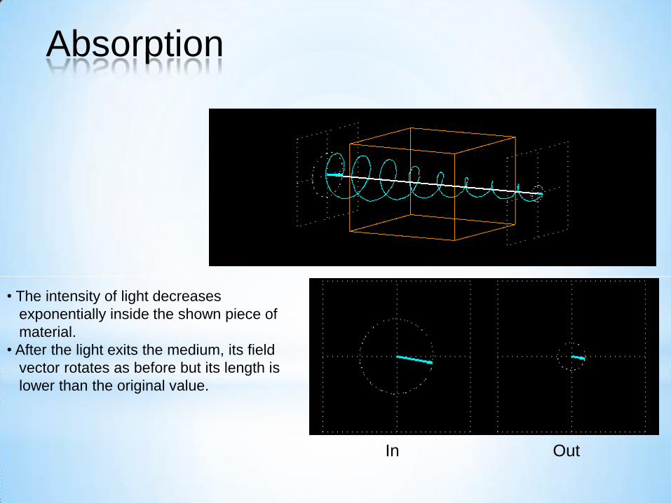
In Out
• The intensity of light decreases
exponentially inside the shown piece of
material.
• After the light exits the medium, its field
vector rotates as before but its length is
lower than the original value.
Absorption
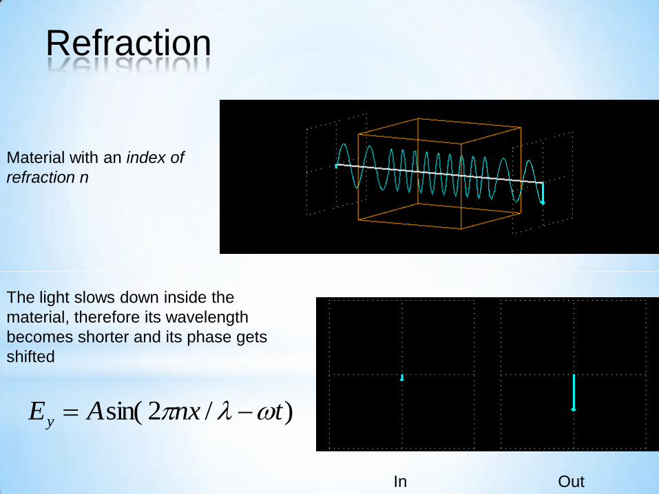
In Out
Material with an index of
refraction n
The light slows down inside the
material, therefore its wavelength
becomes shorter and its phase gets
shifted
)/2sin( tnxAEy
Refraction
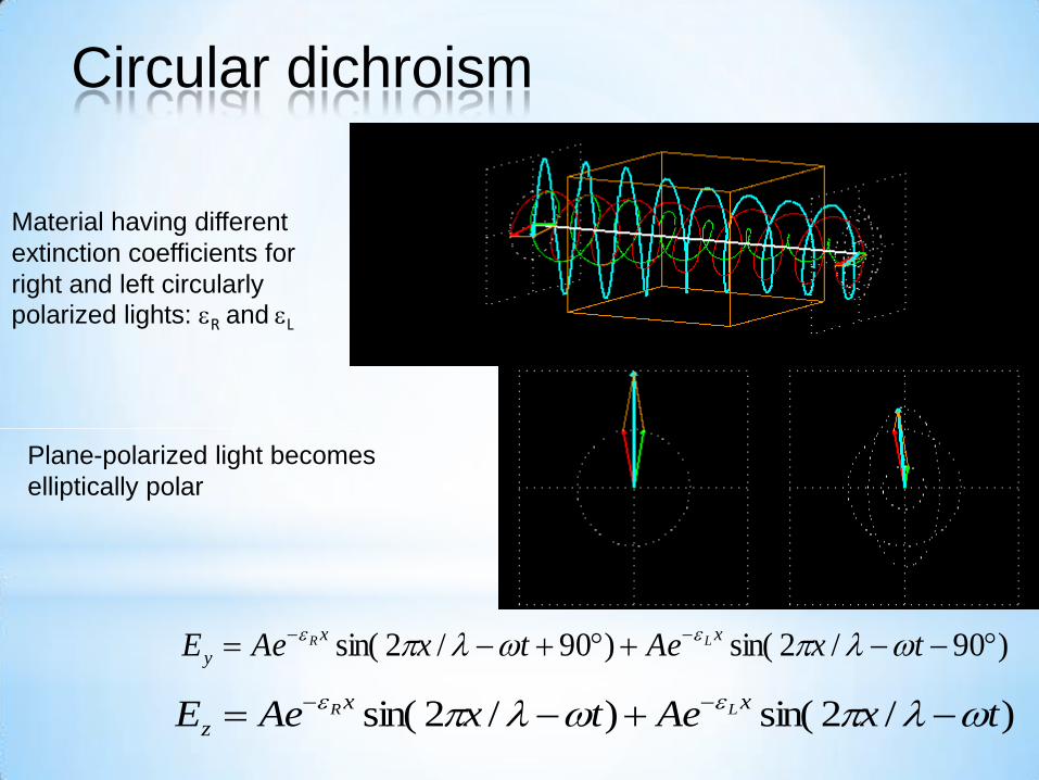
In Out
Material having different
extinction coefficients for
right and left circularly
polarized lights: R and L
Plane-polarized light becomes
elliptically polar
)90/2sin()90/2sin(
txAetxAeExx
yLR
)/2sin()/2sin( txAetxAeExx
zLR
Circular dichroism
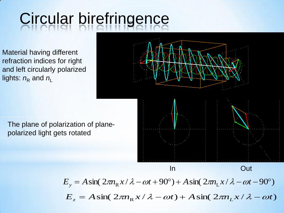
In Out
Material having different
refraction indices for right
and left circularly polarized
lights: nR and nL
The plane of polarization of plane-
polarized light gets rotated
)90/2sin()90/2sin( LR txnAtxnAEy
)/2sin()/2sin( R txnAtxnAE Lz
Circular birefringence
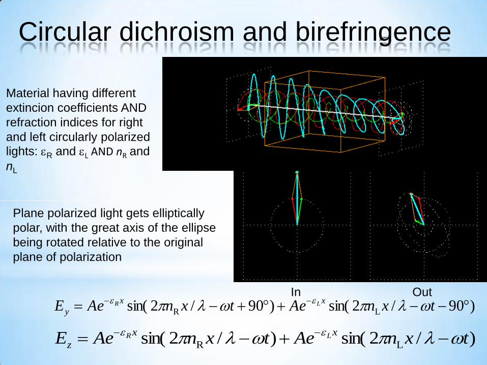
In Out
Material having different
extincion coefficients AND
refraction indices for right
and left circularly polarized
lights: R and L AND nR and
nL
Plane polarized light gets elliptically
polar, with the great axis of the ellipse
being rotated relative to the original
plane of polarization
)90/2sin()90/2sin( LR
txnAetxnAeExx
yLR
)/2sin()/2sin( LR txnAetxnAeExx
zLR
Circular dichroism and birefringence
• Rayleigh
• Mie
• Geometric
The process whereby EM radiation is absorbed and immediately
re-emitted by a particle or molecule – energy can be emitted in
multiple-directions
The type of scattering is controlled by the size of the wavelength relative
to the size of the particle
Light scattering

NOON
• less atmosphere
• less scattering
• blue sky, yellow sun
SUNSET
• more atmosphere
• more scattering
• orange-red sky & sun
• Molecules in atmosphere
scatter light rays.
• Shorter wavelengths (blue, violet) are
scattered more easily.
Light scattering
Blue sky and red sunset

• Wavelength of light is much larger than scattering particles,
• Blue light ~4000 Angstroms, scattering particles ~1 Angstrom (1A=10-10 m)
Rayleigh scattering
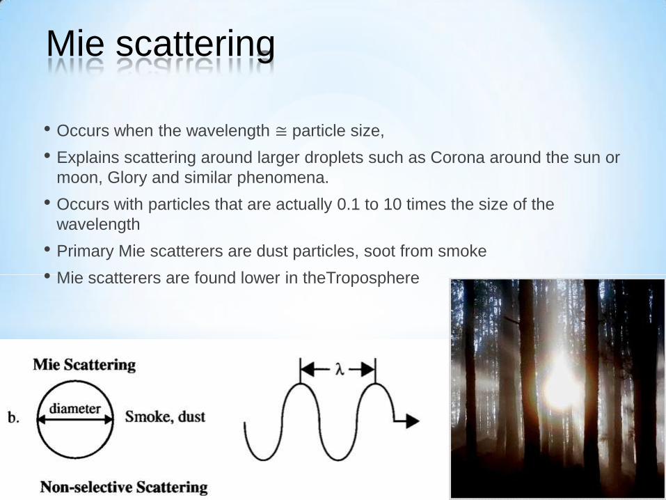
• Occurs when the wavelength ≅ particle size,
• Explains scattering around larger droplets such as Corona around the sun or
moon, Glory and similar phenomena.
• Occurs with particles that are actually 0.1 to 10 times the size of the
wavelength
• Primary Mie scatterers are dust particles, soot from smoke
• Mie scatterers are found lower in theTroposphere
Mie scattering
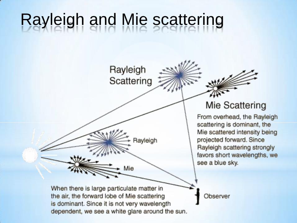
Rayleigh and Mie scattering
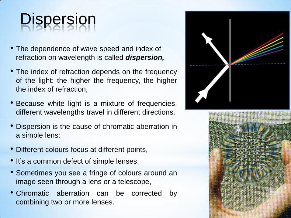
• The dependence of wave speed and index of
refraction on wavelength is called dispersion,
• The index of refraction depends on the frequency
of the light: the higher the frequency, the higher
the index of refraction,
• Because white light is a mixture of frequencies,
different wavelengths travel in different directions.
• Dispersion is the cause of chromatic aberration in
a simple lens:
• Different colours focus at different points,
• It’s a common defect of simple lenses,
• Sometimes you see a fringe of colours around an
image seen through a lens or a telescope,
• Chromatic aberration can be corrected by
combining two or more lenses.
Dispersion
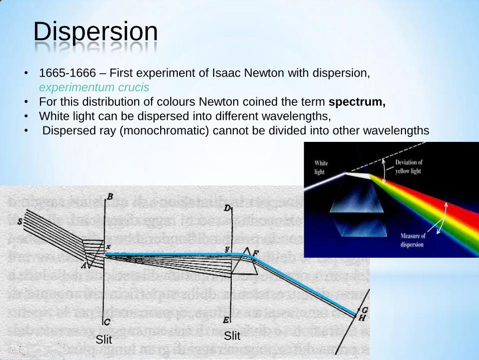
• 1665-1666 – First experiment of Isaac Newton with dispersion,
experimentum crucis
• For this distribution of colours Newton coined the term spectrum,
• White light can be dispersed into different wavelengths,
• Dispersed ray (monochromatic) cannot be divided into other wavelengths
Dispersion
*
Slit Slit
• White light is a “Heterogeneous mixture of different refrangible Rays”
• Colours of the spectrum cannot be individually modified.
• Colours are “Original and connate properties, which in divers Rays
are divers. Some Rays are disposed to exhibit a red colour and no
other; some a yellow and no other, some a green and no other, and
so of the rest”.
Dispersion – Newton’s conclusions
*
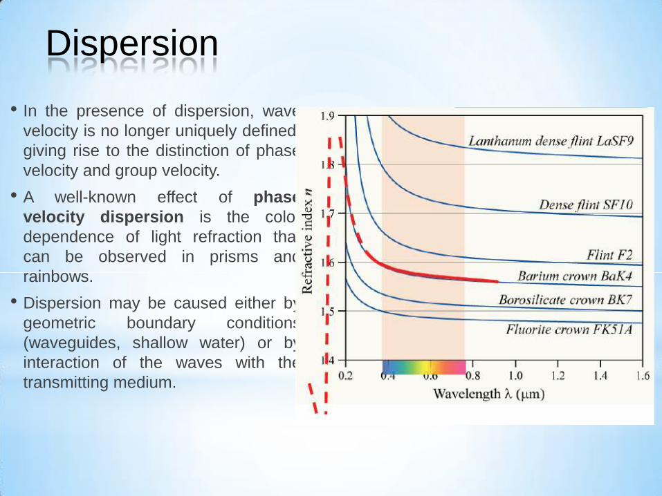
• In the presence of dispersion, wave
velocity is no longer uniquely defined,
giving rise to the distinction of phase
velocity and group velocity.
• A well-known effect of phase
velocity dispersion is the color
dependence of light refraction that
can be observed in prisms and
rainbows.
• Dispersion may be caused either by
geometric boundary conditions
(waveguides, shallow water) or by
interaction of the waves with the
transmitting medium.
Dispersion

• is the phenomenon in which the phase velocity of a wave depends on its
frequency, or alternatively when the group velocity depends on the frequency.
• Media having such a property are termed dispersive media. Dispersion is
sometimes called chromatic dispersion to emphasize its wavelength-
dependent nature, or group-velocity dispersion (GVD) to emphasize the
role of the group velocity.
• Dispersion is called normal when the refractive index decreases with the
wavelength,
• For materials with selective absorption
the refractive index can increase in
some selective wavelength ranges…
• This kind of dispersion is called
anomalous.
Dispersion
Refr
active index
(n)
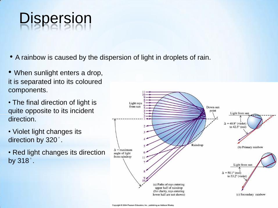
• A rainbow is caused by the dispersion of light in droplets of rain.
• When sunlight enters a drop,
it is separated into its coloured
components.
• The final direction of light is
quite opposite to its incident
direction.
• Violet light changes its
direction by 320°.
• Red light changes its direction
by 318°.
Dispersion
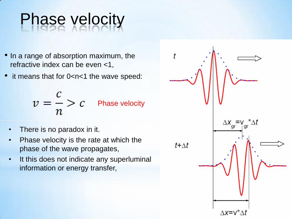
• In a range of absorption maximum, the
refractive index can be even <1,
• it means that for 0<n<1 the wave speed:
• There is no paradox in it.
• Phase velocity is the rate at which the
phase of the wave propagates,
• It this does not indicate any superluminal
information or energy transfer,
Phase velocity
Phase velocity

• The group velocity of a wave is the velocity with which the overall shape of
the wave's amplitudes — known as the modulation or envelope of the wave
— propagates through space.
• The group velocity is often thought of as the velocity at which energy or
information is conveyed along a wave.
• In most cases this is accurate, and the group velocity can be thought of as
the signal velocity of the waveform.
• However, if the wave is travelling through an absorptive medium, this does
not always hold.
Group velocity
• various experiments have verified that it is possible for the group velocity of laser light
pulses sent through specially prepared materials to significantly exceed the speed of
light in vacuum,
• However, superluminal communication is not possible in this case, since the signal
velocity remains less than the speed of light.
• It is also possible to reduce the group velocity to zero, stopping the pulse, or have
negative group velocity, making the pulse appear to propagate backwards.
• However, in all these cases, photons continue to propagate at the expected speed of
light in the medium
• 1999 Rowland Institute for Science, Cambridge,
• 2000 NEC Research Institute, Princton,
Group velocity (equal to an electron's speed) should not be confused with phase
velocity (equal to the product of the electron's frequency multiplied by its
wavelength).
Phase and group velocity

• In a dispersive medium, the phase velocity varies with frequency and is not
necessarily the same as the group velocity of the wave, which is the rate at
which changes in amplitude (known as the envelope of the wave) propagate.
• In some specific cases the phase velocity has a negative sign as group
velocity.
moves with the phase velocity,
moves with the group velocity
Phase and group velocity
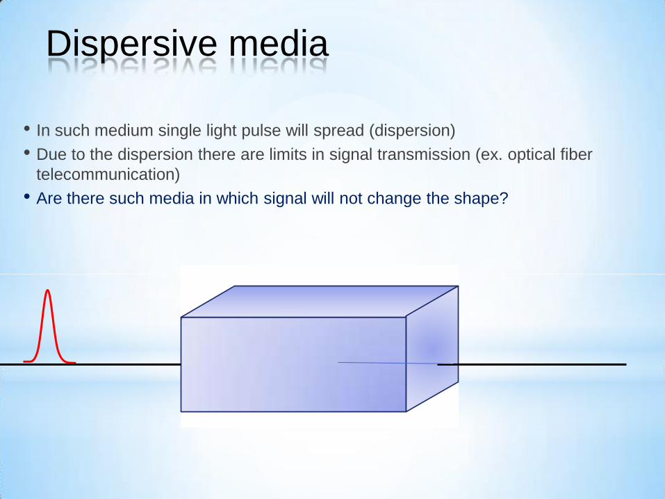
• In such medium single light pulse will spread (dispersion)
• Due to the dispersion there are limits in signal transmission (ex. optical fiber
telecommunication)
• Are there such media in which signal will not change the shape?
Dispersive media
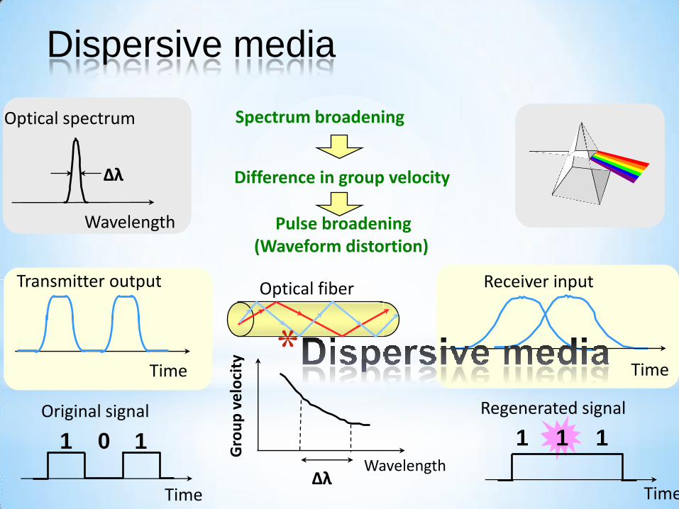
Spectrum broadening
Difference in group velocity
Wavelength
Gro
up
ve
loci
ty
Δλ
1
Time
1 0
Original signal
Time
Transmitter output
Time
Receiver input
Time
1 1 1
Regenerated signal
Wavelength
Optical spectrum
Δλ
Pulse broadening (Waveform distortion)
Optical fiber
*
Dispersive media
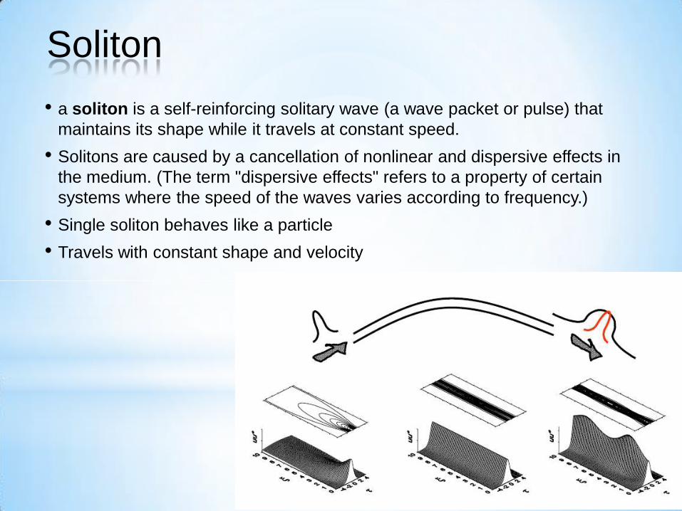
• a soliton is a self-reinforcing solitary wave (a wave packet or pulse) that
maintains its shape while it travels at constant speed.
• Solitons are caused by a cancellation of nonlinear and dispersive effects in
the medium. (The term "dispersive effects" refers to a property of certain
systems where the speed of the waves varies according to frequency.)
• Single soliton behaves like a particle
• Travels with constant shape and velocity
Soliton
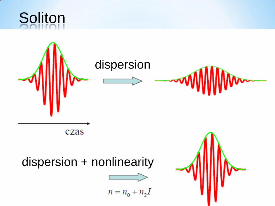
dispersion
dispersion + nonlinearity
Soliton
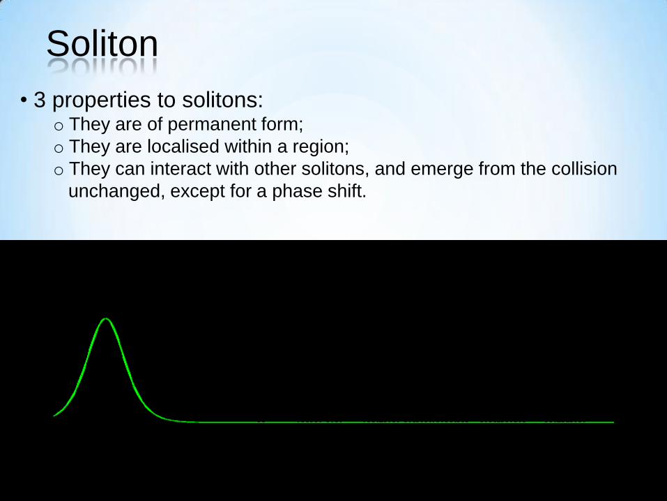
• 3 properties to solitons: o They are of permanent form;
o They are localised within a region;
o They can interact with other solitons, and emerge from the collision
unchanged, except for a phase shift.
Soliton

• The soliton phenomenon was first
described by John Scott Russell (1808–
1882)
• Observation in 1834 in canal near
Edinburgh
• He reproduced the phenomenon in a
wave tank and named it the "Wave of
Translation".
• Large “wave of translation” which did
not dissipate
“Happiest day of my life”
John Scott-Russell’s Soliton

John Scott-Russell’s Soliton
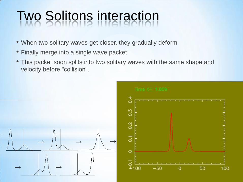
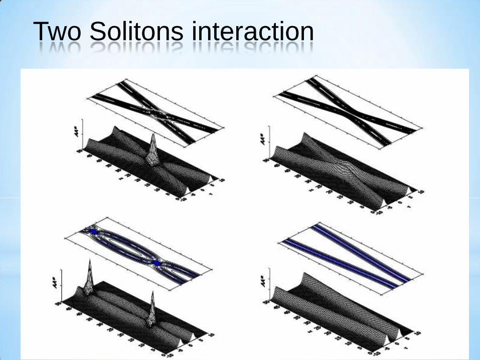
• When two solitary waves get closer, they gradually deform
• Finally merge into a single wave packet
• This packet soon splits into two solitary waves with the same shape and
velocity before "collision".
Two Solitons interaction
Two Solitons interaction
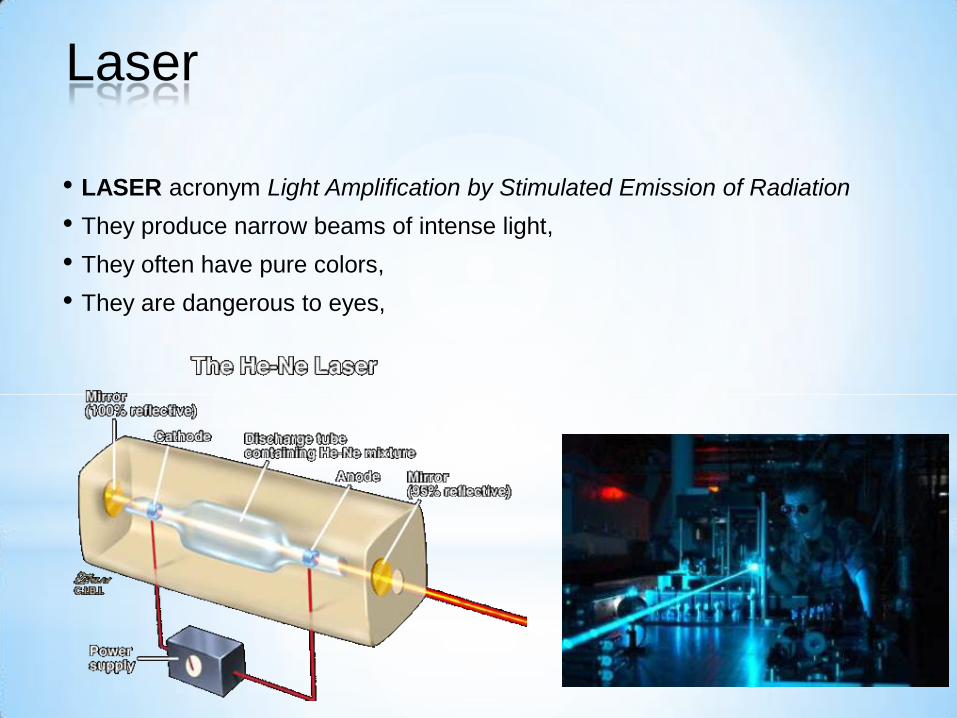
• LASER acronym Light Amplification by Stimulated Emission of Radiation
• They produce narrow beams of intense light,
• They often have pure colors,
• They are dangerous to eyes,
Laser

• Excited atoms normally emit light spontaneously
• Photons are uncorrelated and independent
• Incoherent light
Spontaneous emission
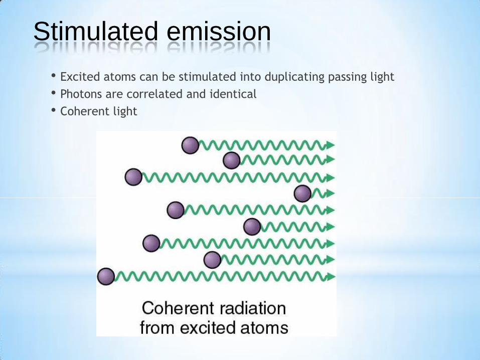
• Excited atoms can be stimulated into duplicating passing light
• Photons are correlated and identical
• Coherent light
Stimulated emission
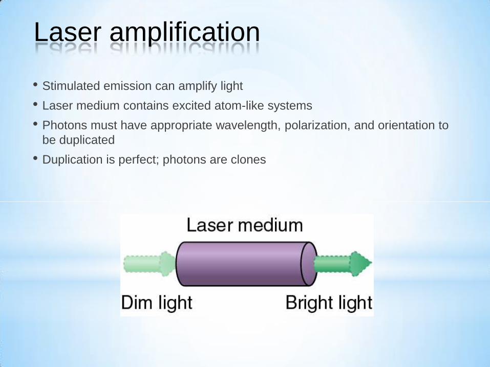
• Stimulated emission can amplify light
• Laser medium contains excited atom-like systems
• Photons must have appropriate wavelength, polarization, and orientation to
be duplicated
• Duplication is perfect; photons are clones
Laser amplification
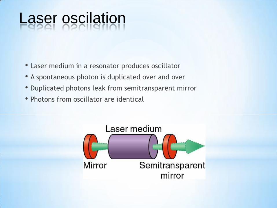
• Laser medium in a resonator produces oscillator
• A spontaneous photon is duplicated over and over
• Duplicated photons leak from semitransparent mirror
• Photons from oscillator are identical
Laser oscilation
• Coherent – identical photons
• Controllable wavelength/frequency – nice colors
• Controllable spatial structure – narrow beams
• Controllable temporal structure – short pulses
• Energy storage and retrieval – intense pulses
• Giant interference effects
• Apart from these issues, laser light is just light
Properties of laser light
• Gas (HeNe, CO2, Argon, Krypton)
• Powered by electricity
• Solid state (Ruby, Nd:YAG, Ti:Sapphire, Diode)
• Powered by electricity or light
• Liquid (Dye, Jello)
• Powered by light
• Chemical (HF)
• Nuclear
Types of lasers
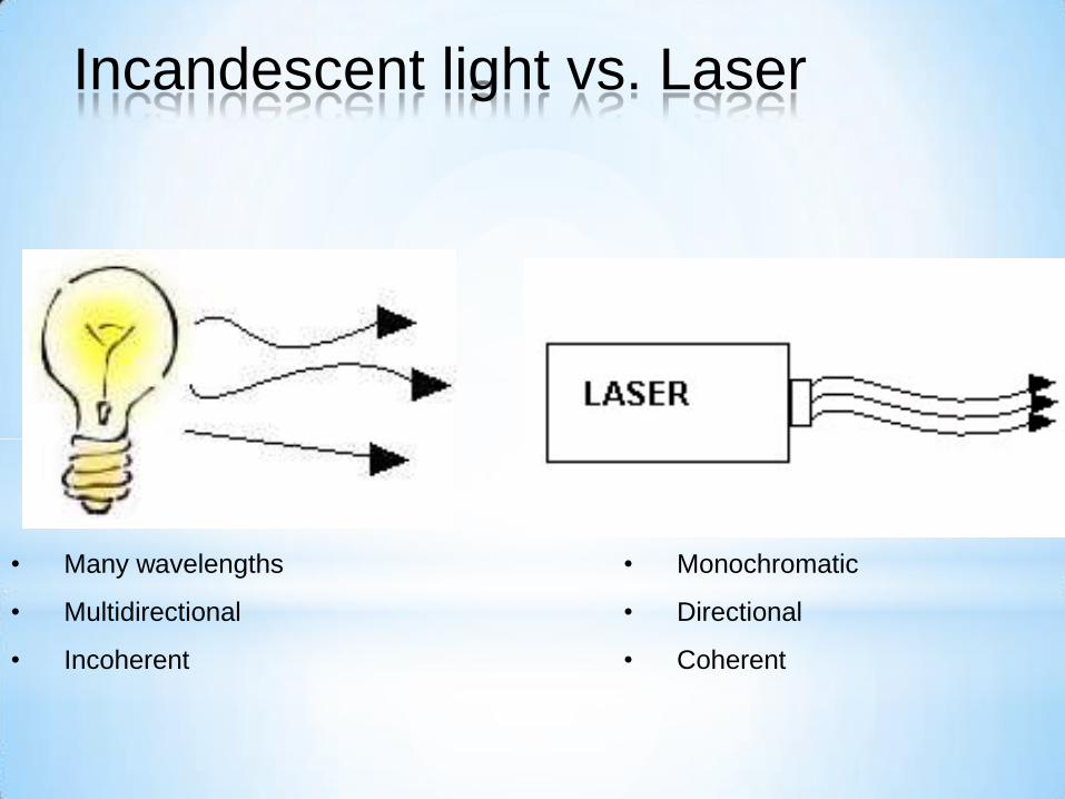
• Many wavelengths
• Multidirectional
• Incoherent
• Monochromatic
• Directional
• Coherent
Incandescent light vs. Laser

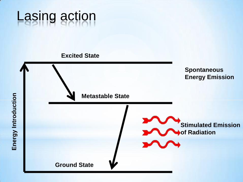
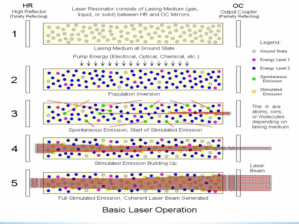
1. Energy is applied to a medium raising electrons to an unstable energy level.
2. These atoms spontaneously decay to a relatively long-lived, lower energy, metastable state.
3. A population inversion is achieved when the majority of atoms have reached this metastable state.
4. Lasing action occurs when an electron spontaneously returns to its ground state and produces a photon.
5. If the energy from this photon is of the precise wavelength, it will stimulate the production of another photon of the same wavelength and resulting in a cascading effect.
6. The highly reflective mirror and partially reflective mirror continue the reaction by directing photons back through the medium along the long axis of the laser.
7. The partially reflective mirror allows the transmission of a small amount of coherent radiation that we observe as the “beam”.
8. Laser radiation will continue as long as energy is applied to the lasing medium.
Lasing action
En
erg
y I
ntr
od
ucti
on
Ground State
Excited State
Metastable State
Spontaneous
Energy Emission
Stimulated Emission
of Radiation
Lasing action
105
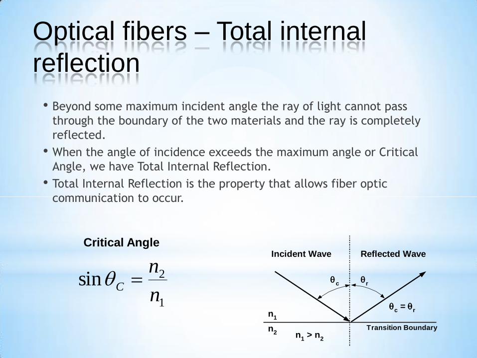
• Beyond some maximum incident angle the ray of light cannot pass
through the boundary of the two materials and the ray is completely
reflected.
• When the angle of incidence exceeds the maximum angle or Critical
Angle, we have Total Internal Reflection.
• Total Internal Reflection is the property that allows fiber optic
communication to occur.
n1
n2 n
1 > n
2
c
r
c =
r
Incident Wave Reflected Wave
Transition Boundary
1
2sinn
nC
Critical Angle
Optical fibers – Total internal
reflection
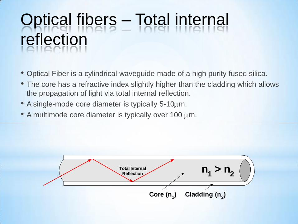
• Optical Fiber is a cylindrical waveguide made of a high purity fused silica.
• The core has a refractive index slightly higher than the cladding which allows
the propagation of light via total internal reflection.
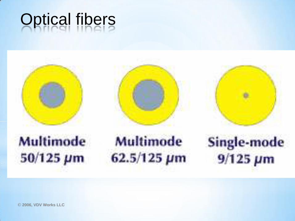
• A single-mode core diameter is typically 5-10m.
• A multimode core diameter is typically over 100 m.
Cladding (n2)Core (n
1)
n1 > n
2Total Internal
Reflection
Optical fibers – Total internal
reflection
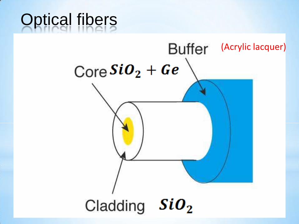
(Acrylic lacquer)
Optical fibers
© 2006, VDV Works LLC
*
Optical fibers
© 2006, VDV Works LLC
Optical fibers
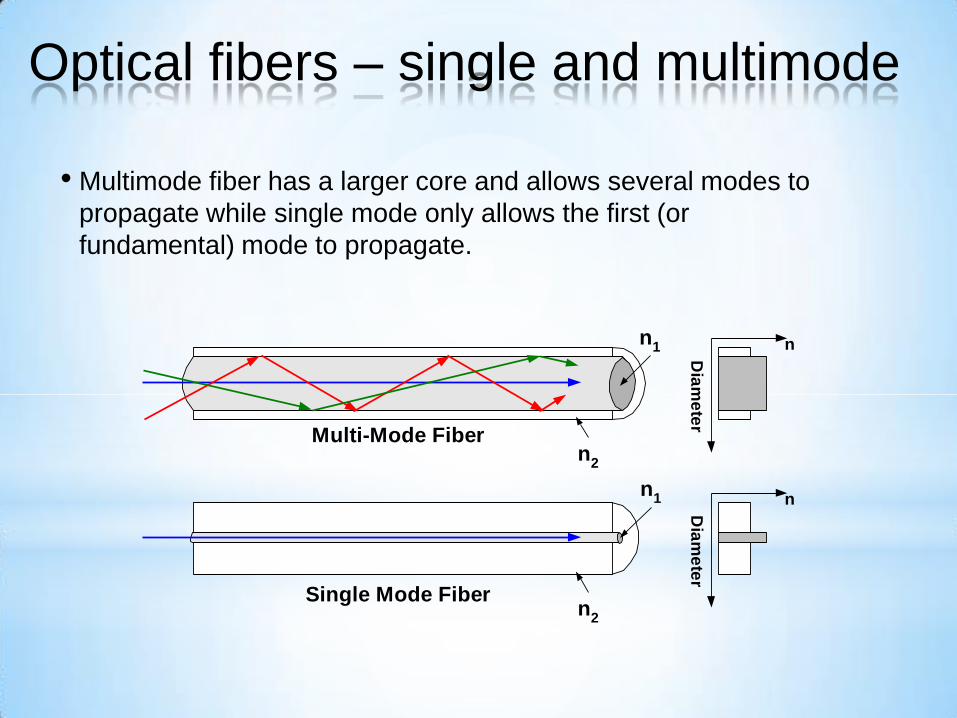
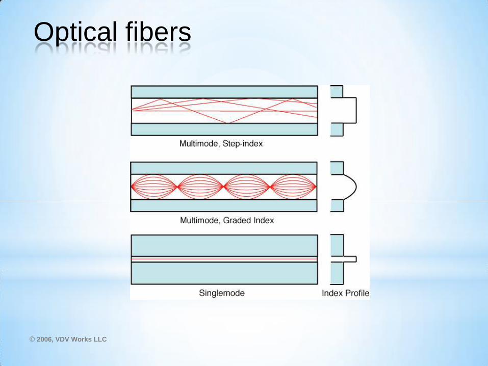
• Multimode fiber has a larger core and allows several modes to
propagate while single mode only allows the first (or
fundamental) mode to propagate.
n2
n1 n
Dia
me
ter
n2
n1 n
Dia
me
ter
Single Mode Fiber
Multi-Mode Fiber
Optical fibers – single and multimode
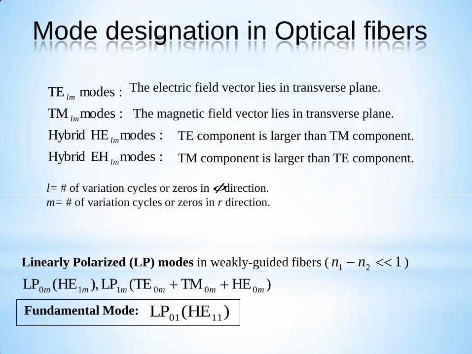
:modesEH Hybrid
:modesHE Hybrid
:modesTM
:modes TE
lm
lm
lm
lmThe electric field vector lies in transverse plane.
The magnetic field vector lies in transverse plane.
TE component is larger than TM component.
TM component is larger than TE component.
l= # of variation cycles or zeros in direction.
m= # of variation cycles or zeros in r direction.
f
Linearly Polarized (LP) modes in weakly-guided fibers ( ) 121 nn
)HETMTE(LP),HE(LP 000110 mmmmmm
Fundamental Mode: )HE(LP 1101
Mode designation in Optical fibers
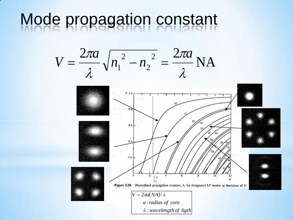
NA22 2
2
2
1
ann
aV
Mode propagation constant
ligthofwavelength
coreofradiusa
NAaV
:
:
/2
2.405
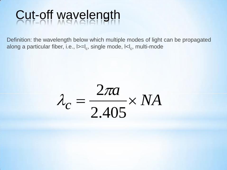
Definition: the wavelength below which multiple modes of light can be propagated
along a particular fiber, i.e., l>=lc, single mode, l<lc, multi-mode
NAa
c 405.2
2
Cut-off wavelength
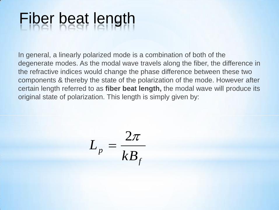
In general, a linearly polarized mode is a combination of both of the
degenerate modes. As the modal wave travels along the fiber, the difference in
the refractive indices would change the phase difference between these two
components & thereby the state of the polarization of the mode. However after
certain length referred to as fiber beat length, the modal wave will produce its
original state of polarization. This length is simply given by:
f
pkB
L2
Fiber beat length
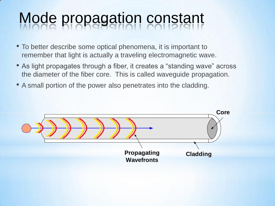
• To better describe some optical phenomena, it is important to
remember that light is actually a traveling electromagnetic wave.
• As light propagates through a fiber, it creates a “standing wave” across
the diameter of the fiber core. This is called waveguide propagation.
• A small portion of the power also penetrates into the cladding.
Cladding
Core
Propagating
Wavefronts
Mode propagation constant
850 940 1030 1120 1210 1300 1390 1480 1570 1660 17500
0.25
0.5
0.75
1
1.25
1.5
1.75
2
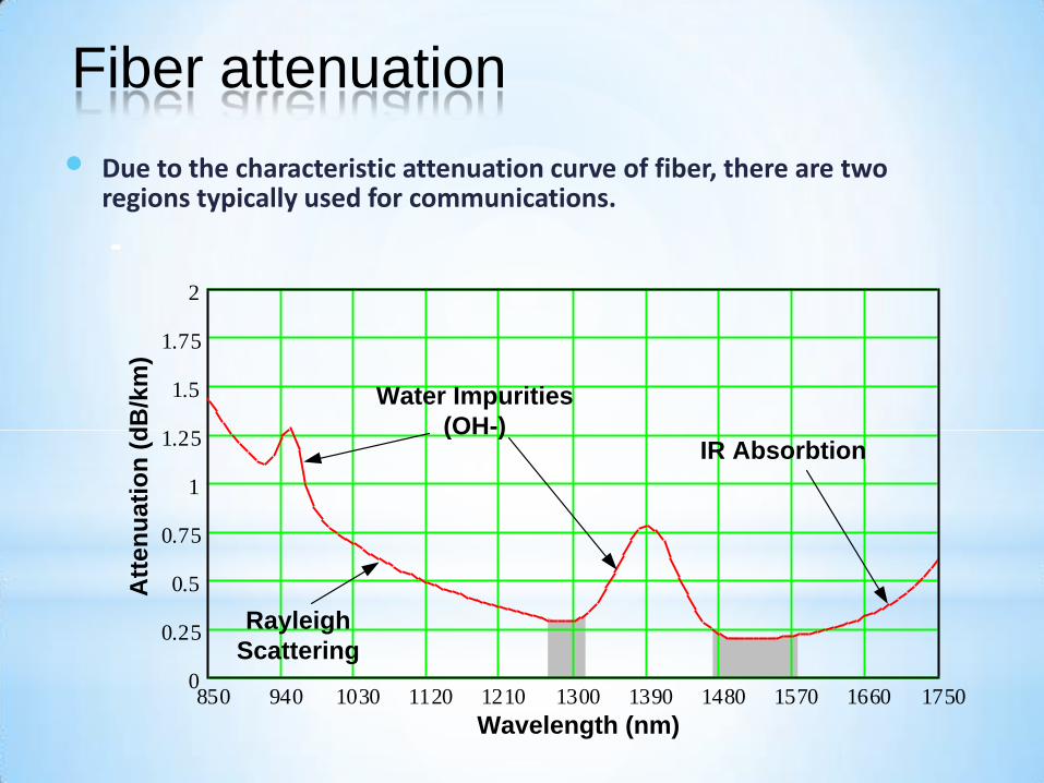
Water Impurities
(OH-)IR Absorbtion
Rayleigh
Scattering
Wavelength (nm)
Att
en
ua
tio
n (
dB
/km
)
• Due to the characteristic attenuation curve of fiber, there are two regions typically used for communications.
Fiber attenuation

3 main types of Photonic Crystal Fibers
Isotropic with solid core Hollow-core Birefringent with solid core
• 2-dimmensional photonic crystals with deffect along the fiber length inside
the core region,
• made of one type of glass material with periodic matrix of air micro-holes
forming a structure of photonic crystal,
Photonic Crystal Fibers

D
d
Λ
•Pitch,
• Large hole diameter, D
• Small hole diameter, d
• Diameter of holey region
• Filling factor, d/
4.4 m
4.5 m
2.2 m
40 m
0.5
Commercially available birefringent PCF from NKTPhotonics
Parameters
Photonic Crystal Fibers

m-TIR (modified Total Internal Reflection) – characteristic for PCFs with solid
core,
PBG (Photonic Band Gap) – characteristic for „hollow-core” PCFs,
Propagation mechanisms in PCF
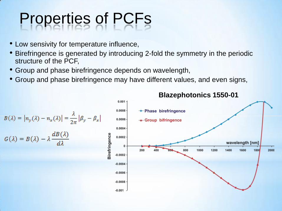
• Low sensivity for temperature influence,
• Birefringence is generated by introducing 2-fold the symmetry in the periodic structure of the PCF,
• Group and phase birefringence depends on wavelength,
• Group and phase birefringence may have different values, and even signs,
Blazephotonics 1550-01
Properties of PCFs

The highest level of tunability of propagation and
polarization properties by external fields
Thermal, external ac & dc
fields, optical field sensitivity
Variety of LC materials and LC
structures; influence of
molecular ordering
Advantages of both
mTIR and PBG phenomena
Variety of PCF structures
(birefringence, SM,
nonlinearity, etc.)
Liquid Crystal Photonic Crystal Fiber Liquid Crystals Photonic Fibers
Photonic Liquid Crystal Fibers