Physics 202, Lecture 10 Basic Circuit Components - IceCube
11
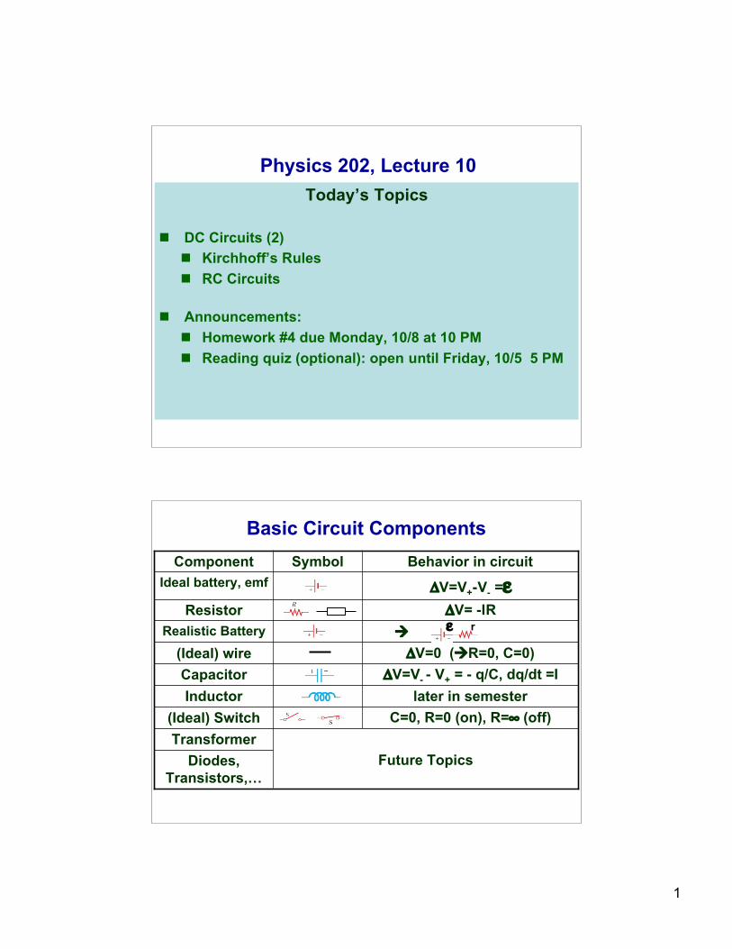
1 Physics 202, Lecture 10 Today’s Topics DC Circuits (2) Kirchhoff’s Rules RC Circuits Announcements: Homework #4 due Monday, 10/8 at 10 PM Reading quiz (optional): open until Friday, 10/5 5 PM Basic Circuit Components Realistic Battery ΔV= -IR Resistor ΔV=V - - V + = - q/C, dq/dt =I Capacitor ΔV=0 (R=0, C=0) (Ideal) wire later in semester Inductor C=0, R=0 (on), R=∞ (off) (Ideal) Switch Diodes, Transistors,… Future Topics Transformer ΔV=V + -V - =ε Ideal battery, emf Behavior in circuit Symbol Component r ε
Transcript of Physics 202, Lecture 10 Basic Circuit Components - IceCube
1
Physics 202, Lecture 10Today’s Topics
DC Circuits (2) Kirchhoff’s Rules RC Circuits
Announcements: Homework #4 due Monday, 10/8 at 10 PM Reading quiz (optional): open until Friday, 10/5 5 PM
Basic Circuit Components
Realistic BatteryΔV= -IRResistor
ΔV=V- - V+ = - q/C, dq/dt =ICapacitorΔV=0 (R=0, C=0)(Ideal) wire
later in semesterInductorC=0, R=0 (on), R=∞ (off)(Ideal) Switch
Diodes,Transistors,…
Future TopicsTransformer
ΔV=V+-V- =εIdeal battery, emfBehavior in circuitSymbolComponent
rε
2
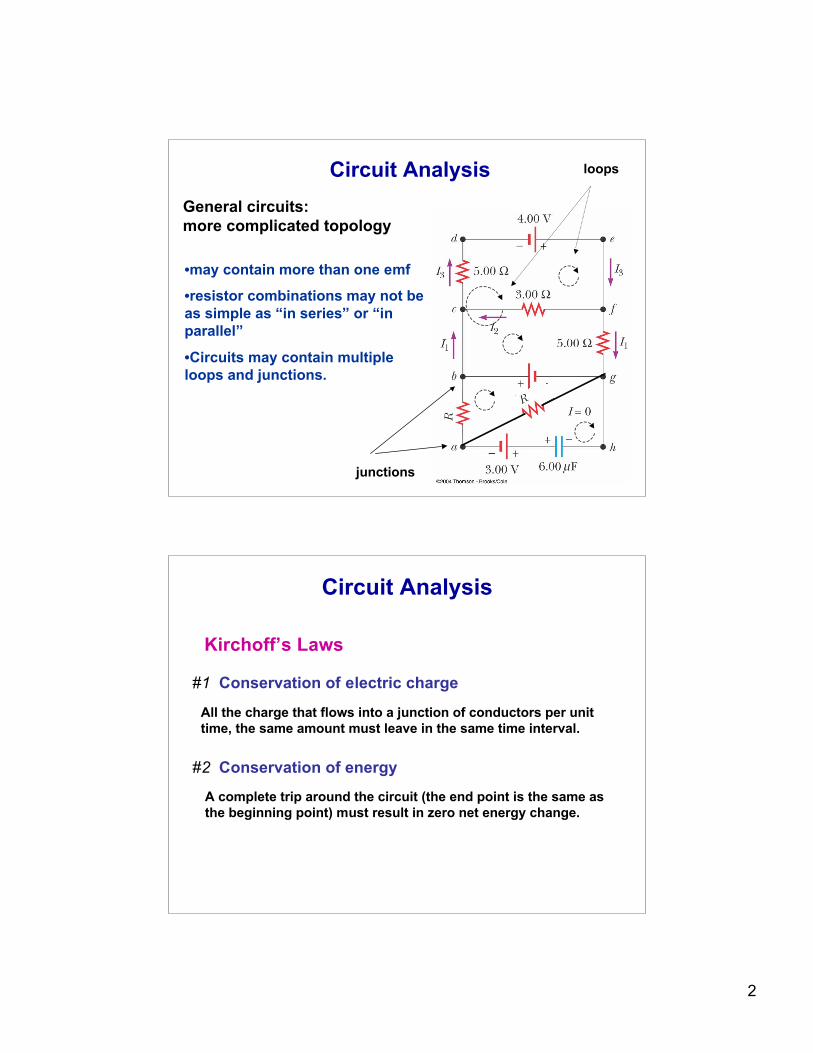
Circuit Analysis
•may contain more than one emf
•resistor combinations may not beas simple as “in series” or “inparallel”
•Circuits may contain multipleloops and junctions.
junctions
loops
General circuits: more complicated topology
Circuit Analysis
Kirchoff’s Laws
#1 Conservation of electric charge
#2 Conservation of energy
All the charge that flows into a junction of conductors per unittime, the same amount must leave in the same time interval.
A complete trip around the circuit (the end point is the same asthe beginning point) must result in zero net energy change.
3
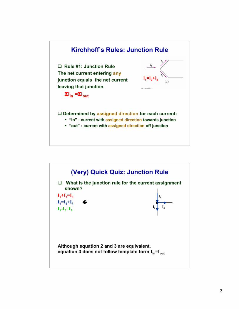
Kirchhoff’s Rules: Junction Rule
Rule #1: Junction RuleThe net current entering anyjunction equals the net currentleaving that junction.
ΣIin =ΣIout
Determined by assigned direction for each current: “in” : current with assigned direction towards junction “out” : current with assigned direction off junction
I1=I2+I3
(Very) Quick Quiz: Junction Rule What is the junction rule for the current assignment
shown?I1+I2=I3
I1=I2+I3
I1-I2=I3
I1
I3I2
Although equation 2 and 3 are equivalent, equation 3 does not follow template form Iin=Iout
4
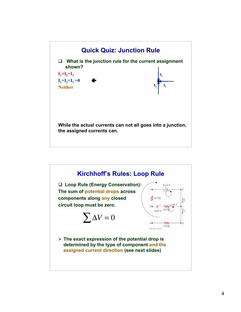
Quick Quiz: Junction Rule What is the junction rule for the current assignment
shown?I1+I2=I3
I1+I2+I3 =0Neither
I1
I3I2
While the actual currents can not all goes into a junction,the assigned currents can.
Kirchhoff’s Rules: Loop Rule Loop Rule (Energy Conservation):The sum of potential drops acrosscomponents along any closedcircuit loop must be zero.
The exact expression of the potential drop isdetermined by the type of component and theassigned current direction (see next slides)
!V" = 0
5
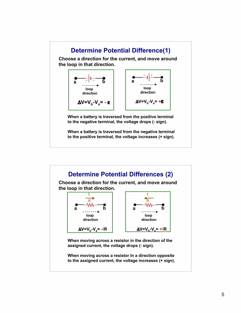
Determine Potential Difference(1)
a bloop
direction
ΔV=Vb-Va= - ε
a bloop
direction
ΔV=Vb-Va= +ε
When a battery is traversed from the positive terminal to the negative terminal, the voltage drops (- sign).
When a battery is traversed from the negative terminal to the positive terminal, the voltage increases (+ sign).
Choose a direction for the current, and move around the loop in that direction.
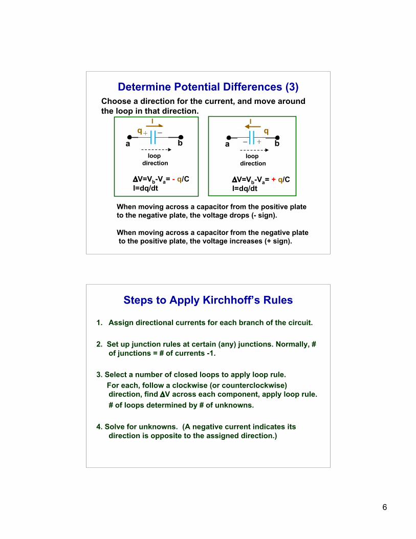
Determine Potential Differences (2)
a bloop
direction
ΔV=Vb-Va= -IR
I
a bloop
direction
ΔV=Vb-Va= +IR
I
When moving across a resistor in the direction of the assigned current, the voltage drops (- sign).
When moving across a resistor In a direction oppositeto the assigned current, the voltage increases (+ sign).
Choose a direction for the current, and move around the loop in that direction.
6
Determine Potential Differences (3)
I
a bloop
direction
ΔV=Vb-Va= - q/CI=dq/dt
qI
a bloop
direction
ΔV=Vb-Va= + q/CI=dq/dt
q
Choose a direction for the current, and move around the loop in that direction.
When moving across a capacitor from the positive plate to the negative plate, the voltage drops (- sign).
When moving across a capacitor from the negative plate to the positive plate, the voltage increases (+ sign).
Steps to Apply Kirchhoff’s Rules
1. Assign directional currents for each branch of the circuit.
2. Set up junction rules at certain (any) junctions. Normally, #of junctions = # of currents -1.
3. Select a number of closed loops to apply loop rule. For each, follow a clockwise (or counterclockwise)
direction, find ΔV across each component, apply loop rule. # of loops determined by # of unknowns.
4. Solve for unknowns. (A negative current indicates itsdirection is opposite to the assigned direction.)
7
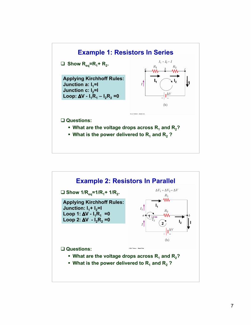
Example 1: Resistors In Series Show Req=R1+ R2.
Questions: What are the voltage drops across R1 and R2? What is the power delivered to R1 and R2 ?
Applying Kirchhoff Rules:Junction a: I1=IJunction c: I2=ILoop: ΔV - I1R1 – I2R2 =0
I1I1 I2 I
Example 2: Resistors In Parallel Show 1/Req=1/R1+ 1/R2.
Questions: What are the voltage drops across R1 and R2? What is the power delivered to R1 and R2 ?
Applying Kirchhoff Rules:Junction: I1+ I2=ILoop 1: ΔV - I1R1 =0Loop 2: ΔV - I2R2 =0
I1
I2 I1
2
8
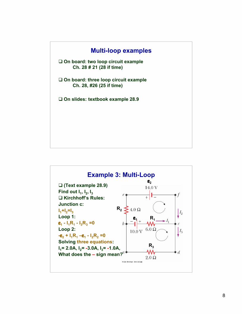
Multi-loop examples On board: two loop circuit example
Ch. 28 # 21 (28 if time)
On board: three loop circuit exampleCh. 28, #26 (25 if time)
On slides: textbook example 28.9
Example 3: Multi-Loop (Text example 28.9)Find out I1, I2, I3 Kirchhoff’s Rules:Junction c:I1+I2=I3Loop 1:ε1 - I1R1 - I3R3 =0Loop 2:-ε2 + I1R1 –ε1 - I2R2 =0Solving three equations:I1= 2.0A, I2= -3.0A, I3= -1.0A,What does the – sign mean?
ε1 R1
R3
R2
ε2
9
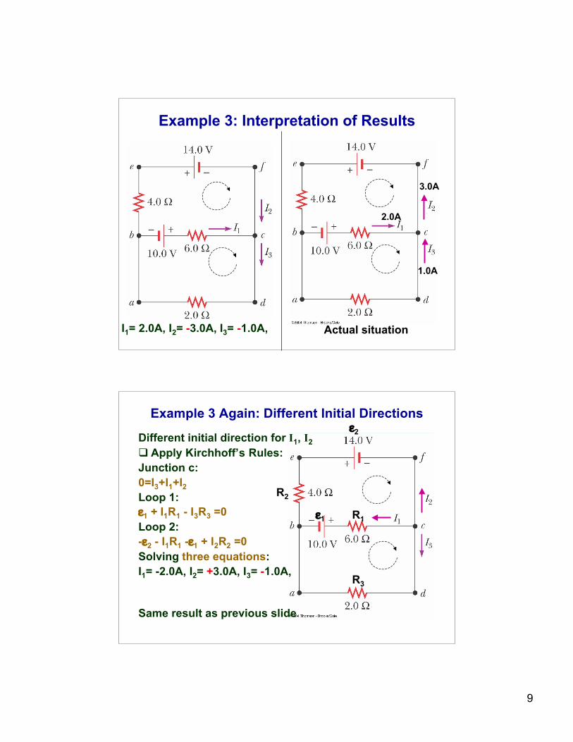
Example 3: Interpretation of Results
2.0A
1.0A
3.0A
I1= 2.0A, I2= -3.0A, I3= -1.0A, Actual situation
Example 3 Again: Different Initial Directions
Different initial direction for I1, I2 Apply Kirchhoff’s Rules:Junction c:0=I3+I1+I2Loop 1:ε1 + I1R1 - I3R3 =0Loop 2:-ε2 - I1R1 -ε1 + I2R2 =0Solving three equations:I1= -2.0A, I2= +3.0A, I3= -1.0A,
Same result as previous slide
ε1 R1
R3
R2
ε2
10
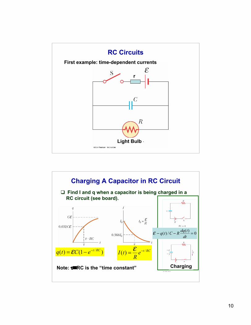
RC Circuits
Light Bulb
r
First example: time-dependent currents
Charging A Capacitor in RC Circuit Find I and q when a capacitor is being charged in a
RC circuit (see board).
Charging
)1()( /RCteCtq!
!= " RCte
RtI
/)( !="
Note: τ≡RC is the “time constant”
0)(
/)( =!!dt
tdqRCtq"
11
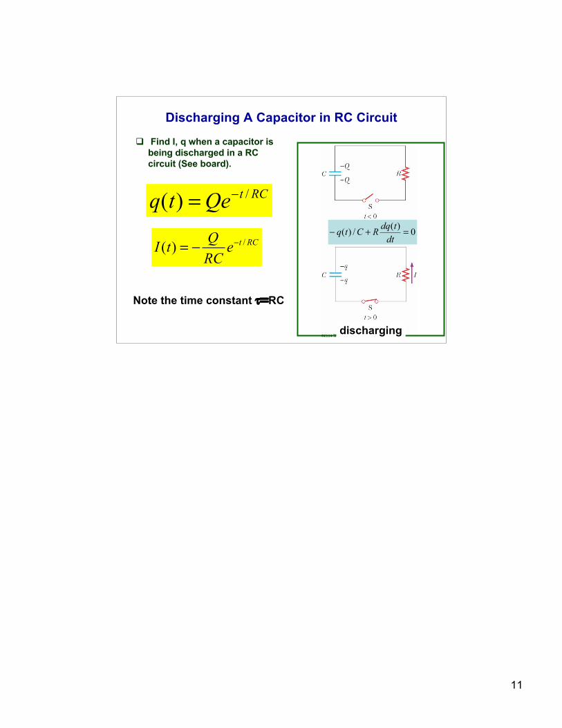
Discharging A Capacitor in RC Circuit
Find I, q when a capacitor isbeing discharged in a RCcircuit (See board).
discharging
RCtQetq
/)( !=
RCte
RC
QtI
/)( !!=
Note the time constant τ=RC
0)(
/)( =+!dt
tdqRCtq