Lecture 23: Modulation, part 1 - MIT OpenCourseWare | … 3 × 10 8 m/s f = ∼ ≈ 3 GHz. λ 10 cm...
40
6.003: Signals and Systems Modulation December 1, 2011 1
Transcript of Lecture 23: Modulation, part 1 - MIT OpenCourseWare | … 3 × 10 8 m/s f = ∼ ≈ 3 GHz. λ 10 cm...

6.003: Signals and Systems
Modulation
December 1, 2011 1
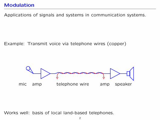
Modulation
Applications of signals and systems in communication systems.
Example: Transmit voice via telephone wires (copper)
mic amp telephone wire amp speaker
Works well: basis of local land-based telephones. 2
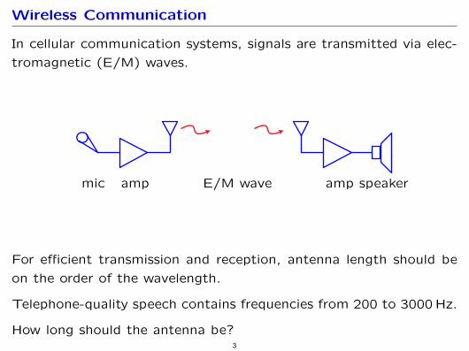
Wireless Communication
In cellular communication systems, signals are transmitted via elec
tromagnetic (E/M) waves.
mic amp E/M wave amp speaker
For efficient transmission and reception, antenna length should be
on the order of the wavelength.
Telephone-quality speech contains frequencies from 200 to 3000 Hz.
How long should the antenna be? 3
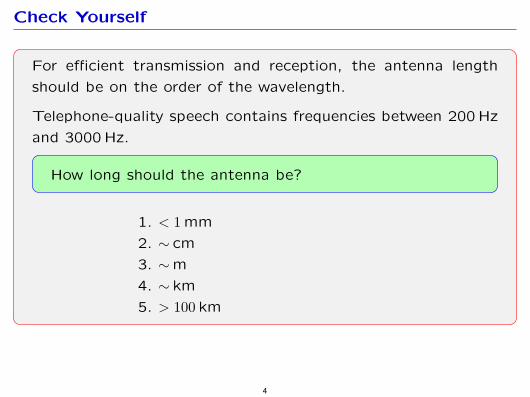
Check Yourself
For efficient transmission and reception, the antenna length
should be on the order of the wavelength.
Telephone-quality speech contains frequencies between 200 Hz
and 3000 Hz.
How long should the antenna be?
1. < 1 mm
2. ∼ cm
3. ∼ m
4. ∼ km
5. > 100 km
4
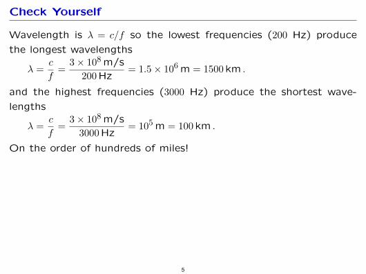
Check Yourself
Wavelength is λ = c/f so the lowest frequencies (200 Hz) produce
the longest wavelengths c 3 × 10⁸ m/s
λ = = = 1.5 × 10⁶ m = 1500 km . f 200 Hz
and the highest frequencies (3000 Hz) produce the shortest wave
lengths c 3 × 10⁸ m/s
λ = = = 105 m = 100 km . f 3000 Hz
On the order of hundreds of miles!
5
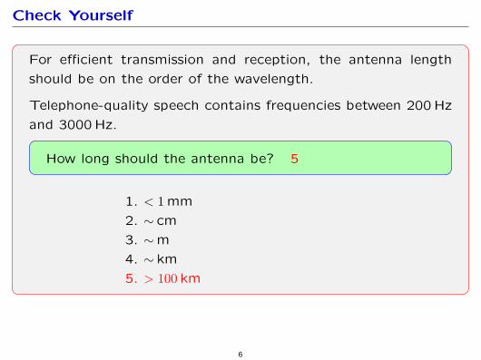
Check Yourself
For efficient transmission and reception, the antenna length
should be on the order of the wavelength.
Telephone-quality speech contains frequencies between 200 Hz
and 3000 Hz.
How long should the antenna be? 5
1. < 1 mm
2. ∼ cm
3. ∼ m
4. ∼ km
5. > 100 km
6
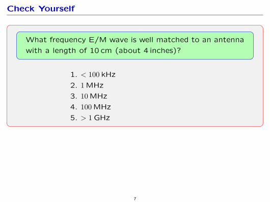
Check Yourself
What frequency E/M wave is well matched to an antenna
with a length of 10 cm (about 4 inches)?
1. < 100 kHz
2. 1 MHz
3. 10 MHz
4. 100 MHz
5. > 1 GHz
7
Check Yourself
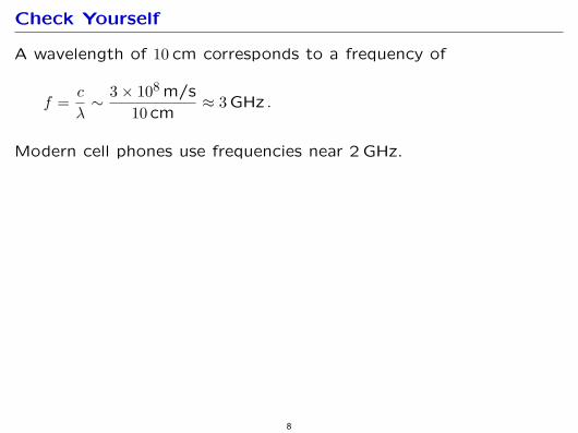
A wavelength of 10 cm corresponds to a frequency of
c 3 × 10⁸ m/sf = ∼ ≈ 3 GHz .
λ 10 cm
Modern cell phones use frequencies near 2 GHz.
8
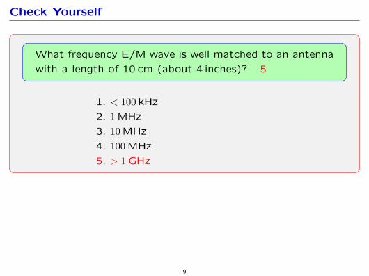
Check Yourself
What frequency E/M wave is well matched to an antenna
with a length of 10 cm (about 4 inches)? 5
1. < 100 kHz
2. 1 MHz
3. 10 MHz
4. 100 MHz
5. > 1 GHz
9
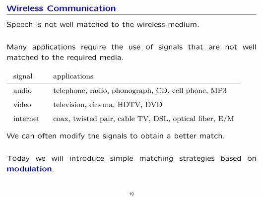
Wireless Communication
Speech is not well matched to the wireless medium.
Many applications require the use of signals that are not well
matched to the required media.
signal applications
audio telephone, radio, phonograph, CD, cell phone, MP3
video television, cinema, HDTV, DVD
internet coax, twisted pair, cable TV, DSL, optical fiber, E/M
We can often modify the signals to obtain a better match.
Today we will introduce simple matching strategies based on
modulation.
10
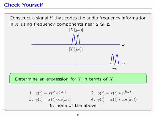
Check Yourself
Construct a signal Y that codes the audio frequency information
in X using frequency components near 2 GHz.
ω
|X(jω)|
ωωc
|Y (jω)|
Determine an expression for Y in terms of X.
1. y(t) = x(t) e jωct 2. y(t) = x(t) ∗ e jωct
3. y(t) = x(t) cos(ωct) 4. y(t) = x(t) ∗ cos(ωct)
5. none of the above
11
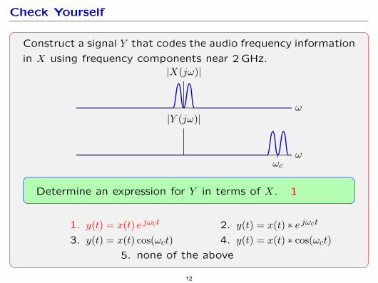
Check Yourself
Construct a signal Y that codes the audio frequency information
in X using frequency components near 2 GHz.
ω
|X(jω)|
ωωc
|Y (jω)|
Determine an expression for Y in terms of X. 1
1. y(t) = x(t) e jωct 2. y(t) = x(t) ∗ e jωct
3. y(t) = x(t) cos(ωct) 4. y(t) = x(t) ∗ cos(ωct)
5. none of the above
12
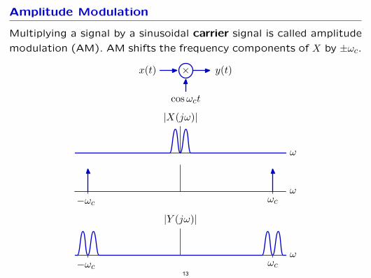
Amplitude Modulation
Multiplying a signal by a sinusoidal carrier signal is called amplitude
modulation (AM). AM shifts the frequency components of X by ±ωc.
×x(t) y(t)
cosωct
ω
|X(jω)|
ωωc−ωc
ωωc−ωc
|Y (jω)|
13
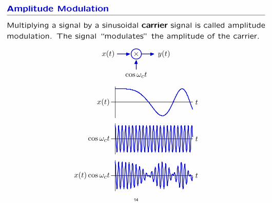
Amplitude Modulation
Multiplying a signal by a sinusoidal carrier signal is called amplitude
modulation. The signal “modulates” the amplitude of the carrier.
×x(t) y(t)
cosωct
tx(t) cosωct
tx(t)
tcosωct
14
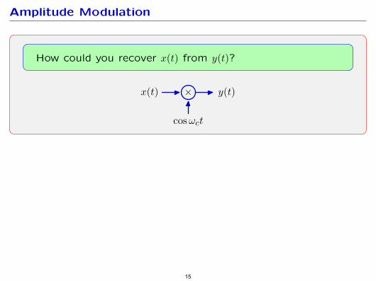
Amplitude Modulation
How could you recover x(t) from y(t)?
×x(t) y(t)
cosωct
15
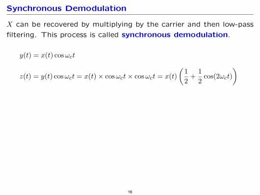
Synchronous Demodulation
X can be recovered by multiplying by the carrier and then low-pass
filtering. This process is called synchronous demodulation.
y(t) = x(t) cos ωct
1 1 z(t) = y(t) cos ωct = x(t) × cos ωct × cos ωct = x(t) + cos(2ωct)2 2
16
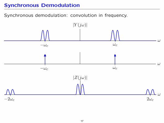
Synchronous Demodulation
Synchronous demodulation: convolution in frequency.
ωωc−ωc
|Y (jω)|
ωωc−ωc
ω2ωc−2ωc
|Z(jω)|
17
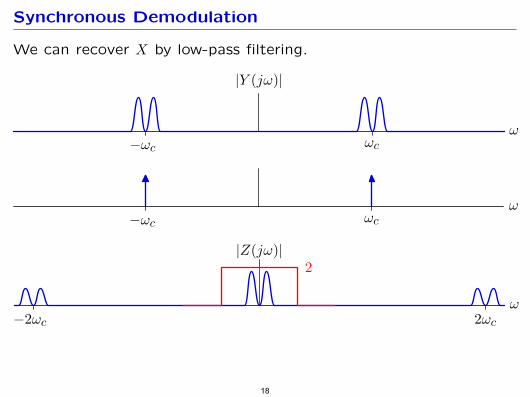
Synchronous Demodulation
We can recover X by low-pass filtering.
ωωc−ωc
|Y (jω)|
ωωc−ωc
ω2ωc−2ωc
|Z(jω)|2
18
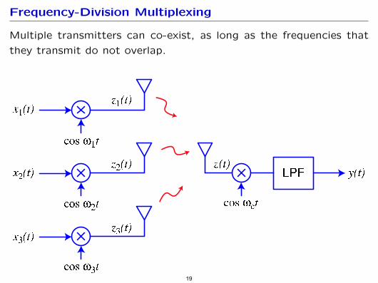
Frequency-Division Multiplexing
Multiple transmitters can co-exist, as long as the frequencies that
they transmit do not overlap.
x1(t)
x2(t)
x3(t)
z1(t)
z2(t) z(t)y(t)
z3(t)
cos w1t
cos w2t cos wct
cos w3t
LPF
19
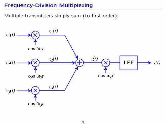
Frequency-Division Multiplexing
Multiple transmitters simply sum (to first order).
x1(t)
x2(t)
x3(t)
z1(t)
z2(t) z(t)y(t)
z3(t)
cos w1t
cos w2t cos wct
cos w3t
LPF
20
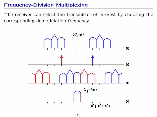
Frequency-Division Multiplexing
The receiver can select the transmitter of interest by choosing the
corresponding demodulation frequency.
Z(jw)
X1(jw)
w
w
w
w
w1 w2 w3
21
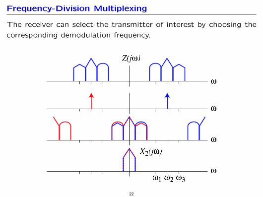
Frequency-Division Multiplexing
The receiver can select the transmitter of interest by choosing the
corresponding demodulation frequency.
Z(jw)
X2(jw)
w
w
w
w
w1 w2 w3
22
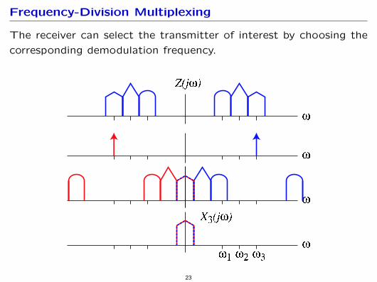
Frequency-Division Multiplexing
The receiver can select the transmitter of interest by choosing the
corresponding demodulation frequency.
Z(jw)
X3(jw)
w
w
w
w
w1 w2 w3
23
Broadcast Radio
“Broadcast” radio was championed by David Sarnoff, who previously
worked at Marconi Wireless Telegraphy Company (point-to-point).
• envisioned “radio music boxes”
• analogous to newspaper, but at speed of light
• receiver must be cheap (as with newsprint)
• transmitter can be expensive (as with printing press)
24
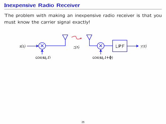
Inexpensive Radio Receiver
The problem with making an inexpensive radio receiver is that you
must know the carrier signal exactly!
z(t)x(t) y(t)
cos(wct) cos(wct+f)
LPF
25
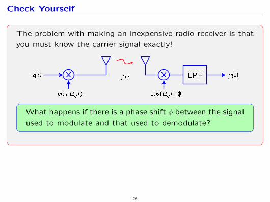
Check Yourself
The problem with making an inexpensive radio receiver is that
you must know the carrier signal exactly!
z(t)x(t) y(t)
cos(wct) cos(wct+f)
LPF
What happens if there is a phase shift φ between the signal
used to modulate and that used to demodulate?
26
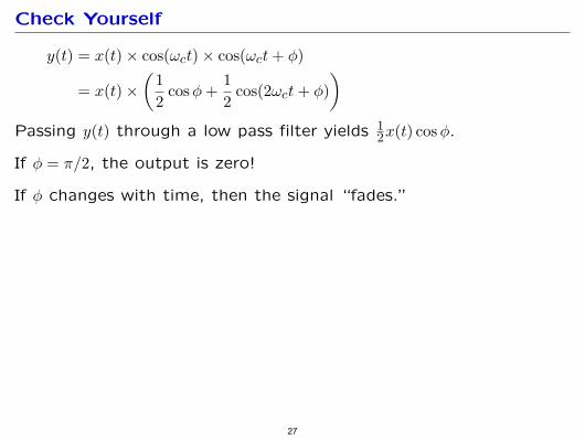
Check Yourself
y(t) = x(t) × cos(ωct) × cos(ωct + φ)
= x(t) × 21 cos φ +
1 cos(2ωct + φ)2
Passing y(t) through a low pass filter yields 12 x(t) cos φ.
If φ = π/2, the output is zero!
If φ changes with time, then the signal “fades.”
27
( )
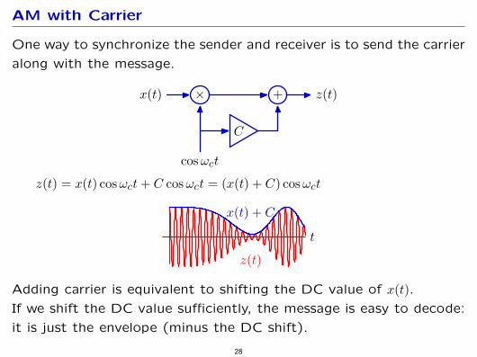
AM with Carrier
One way to synchronize the sender and receiver is to send the carrier
along with the message.
× +
C
x(t) z(t)
cosωct
z(t) = x(t) cos ωct + C cos ωct = (x(t) + C) cos ωct
t
z(t)
x(t) + C
Adding carrier is equivalent to shifting the DC value of x(t). If we shift the DC value sufficiently, the message is easy to decode:
it is just the envelope (minus the DC shift).
28
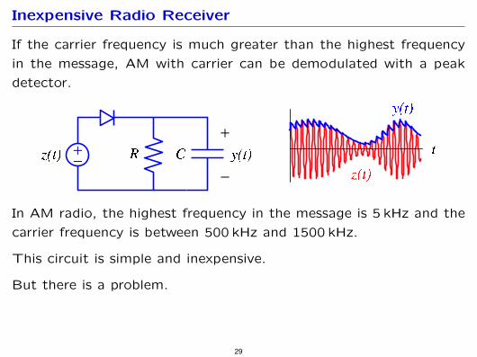
Inexpensive Radio Receiver
If the carrier frequency is much greater than the highest frequency
in the message, AM with carrier can be demodulated with a peak
detector.
z(t)
z(t)
y(t)
R C ty(t)
In AM radio, the highest frequency in the message is 5 kHz and the
carrier frequency is between 500 kHz and 1500 kHz.
This circuit is simple and inexpensive.
But there is a problem.
29
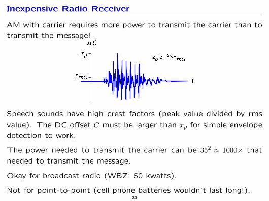
Inexpensive Radio Receiver
AM with carrier requires more power to transmit the carrier than to
transmit the message! x(t)
xp
xrms
xp > 35xrms
t
Speech sounds have high crest factors (peak value divided by rms
value). The DC offset C must be larger than xp for simple envelope
detection to work.
The power needed to transmit the carrier can be 352 ≈ 1000× that
needed to transmit the message.
Okay for broadcast radio (WBZ: 50 kwatts).
Not for point-to-point (cell phone batteries wouldn’t last long!). 30
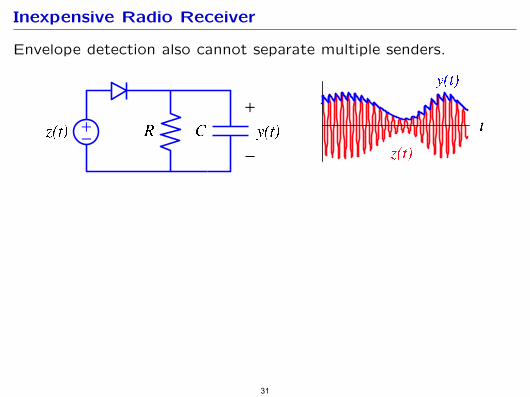
Inexpensive Radio Receiver
Envelope detection also cannot separate multiple senders.
z(t)
z(t)
y(t)
R C ty(t)
31
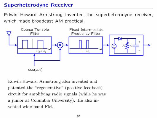
Superheterodyne Receiver
Edwin Howard Armstrong invented the superheterodyne receiver,
which made broadcast AM practical.
Edwin Howard Armstrong also invented and
patented the “regenerative” (positive feedback)
circuit for amplifying radio signals (while he was
a junior at Columbia University). He also invented wide-band FM.
32
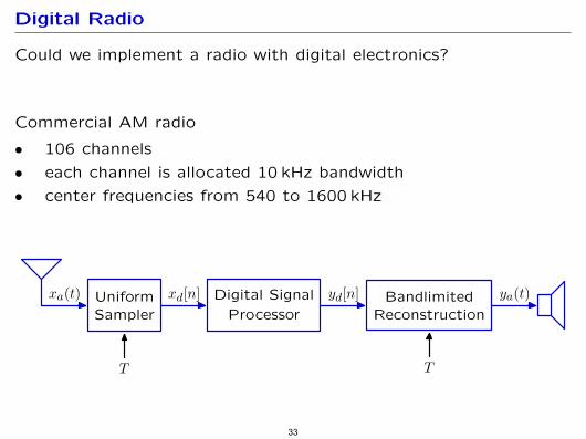
Digital Radio
Could we implement a radio with digital electronics?
Commercial AM radio
• 106 channels
• each channel is allocated 10 kHz bandwidth
• center frequencies from 540 to 1600 kHz
UniformSampler
Digital Signal
ProcessorBandlimited
Reconstruction
xa(t) xd[n] yd[n] ya(t)
T T
33
• each channel is allocated 10 kHz bandwidth
• center frequencies from 540 to 1600 kHz
UniformSampler
Digital Signal
ProcessorBandlimited
Reconstruction
xa(t) xd[n] yd[n] ya(t)
T T
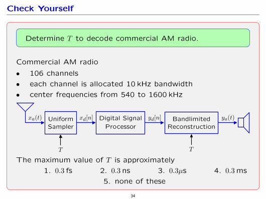
Check Yourself
Determine T to decode commercial AM radio.
Commercial AM radio
• 106 channels
The maximum value of T is approximately
1. 0.3 fs 2. 0.3 ns 3. 0.3µs 4. 0.3 ms
5. none of these
34
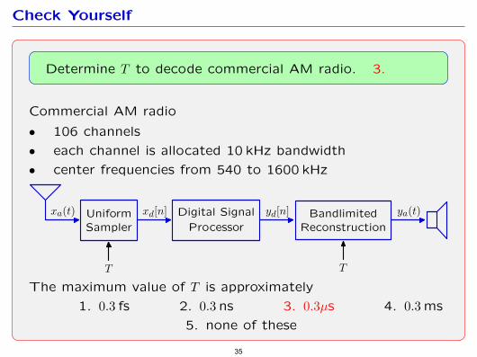
• each channel is allocated 10 kHz bandwidth
• center frequencies from 540 to 1600 kHz
UniformSampler
Digital Signal
ProcessorBandlimited
Reconstruction
xa(t) xd[n] yd[n] ya(t)
T T
Check Yourself
Determine T to decode commercial AM radio. 3.
Commercial AM radio
• 106 channels
The maximum value of T is approximately
1. 0.3 fs 2. 0.3 ns 3. 0.3µs 4. 0.3 ms
5. none of these
35
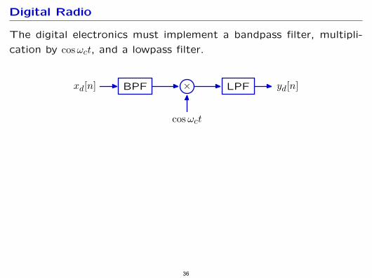
Digital Radio
The digital electronics must implement a bandpass filter, multipli
cation by cos ωct, and a lowpass filter.
BPF × LPFxd[n] yd[n]
cosωct
36
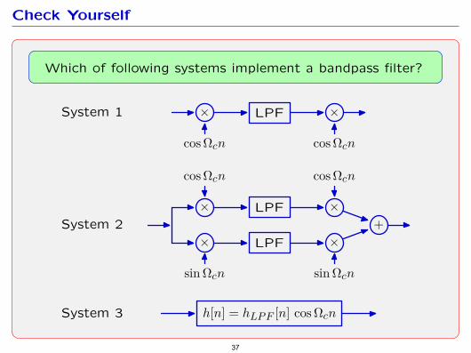
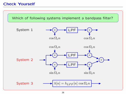
Check Yourself
Which of following systems implement a bandpass filter?
× LPF ×
cos Ωcn cos Ωcn
× LPF ×
cos Ωcn cos Ωcn
× LPF ×
sin Ωcn sin Ωcn
+
h[n] = hLP F [n] cos Ωcn
System 1
System 2
System 3
37
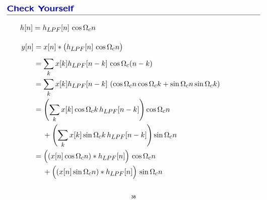
Check Yourself
h[n] = hLP F [n] cos Ωcn y[n] = x[n] ∗ hLP F [n] cos Ωcn
= x[k]hLP F [n − k] cos Ωc(n − k) k
= x[k]hLP F [n − k] (cos Ωcn cos Ωck + sin Ωcn sin Ωck) k
= x[k] cos Ωck hLP F [n − k] cos Ωcn k
+ x[k] sin Ωck hLP F [n − k] sin Ωcn k
= (x[n] cos Ωcn) ∗ hLP F [n] cos Ωcn + (x[n] sin Ωcn) ∗ hLP F [n] sin Ωcn
38
Check Yourself
Which of following systems implement a bandpass filter?
× LPF ×
cos Ωcn cos Ωcn
× LPF ×
cos Ωcn cos Ωcn
× LPF ×
sin Ωcn sin Ωcn
+
h[n] = hLP F [n] cos Ωcn
System 1
System 2
System 3
39
MIT OpenCourseWarehttp://ocw.mit.edu
6.003 Signals and SystemsFall 2011
For information about citing these materials or our Terms of Use, visit: http://ocw.mit.edu/terms.