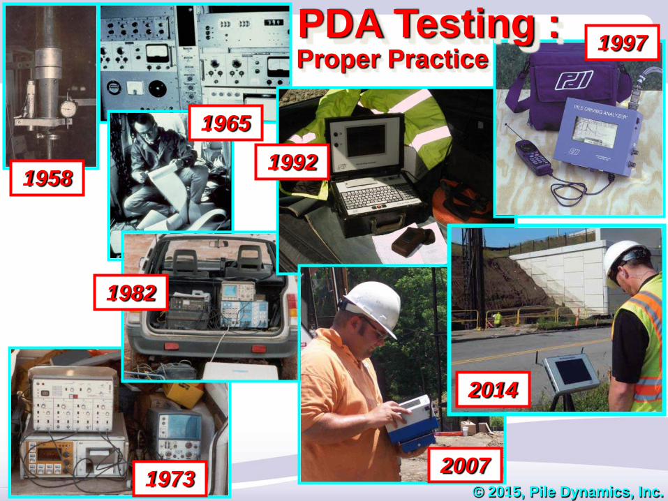
PDA Testing : 1997 Proper Practice
58
1973 1982 1992 1965 1997 PDA Testing : © 2015, Pile Dynamics, Inc. Proper Practice 2007 1958 2014
Transcript of PDA Testing : 1997 Proper Practice
1973
1982
1992
1965
1997PDA Testing :
© 2015, Pile Dynamics, Inc.
Proper Practice
2007
1958
2014
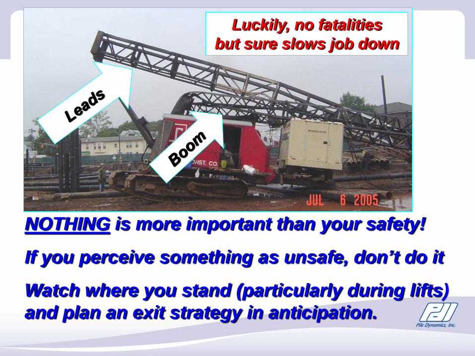
Luckily, no fatalities but sure slows job down
NOTHING is more important than your safety!
If you perceive something as unsafe, don’t do it
Watch where you stand (particularly during lifts) and plan an exit strategy in anticipation.
“Case Method” requires measuring Force ( F ) and Velocity ( V ) versus time at same point on pile (usually near top).
Pile Testing
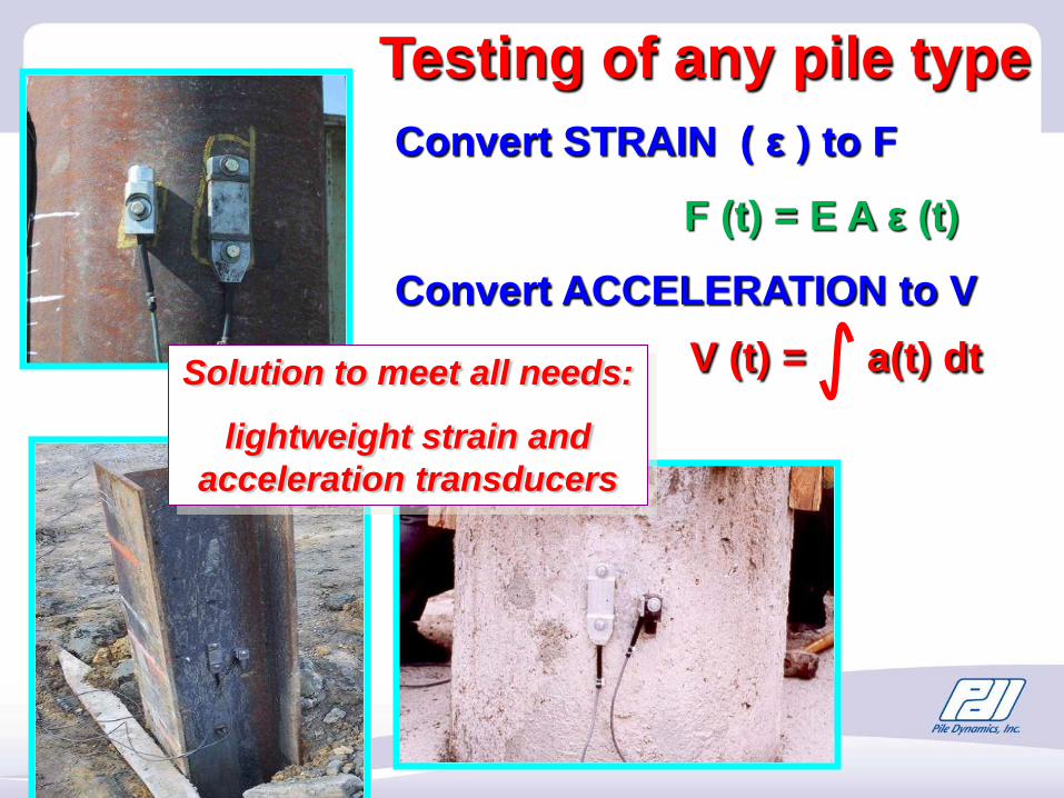
Convert STRAIN ( ε ) to F
F (t) = E A ε (t)
Convert ACCELERATION to V V (t) = a(t) dt
Testing of any pile type
Solution to meet all needs:
lightweight strain and acceleration transducers
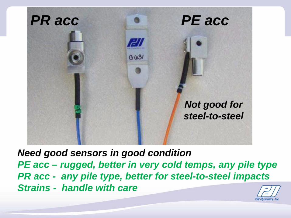
PR acc PE acc
Not good for steel-to-steel
Need good sensors in good conditionPE acc – rugged, better in very cold temps, any pile typePR acc - any pile type, better for steel-to-steel impactsStrains - handle with care
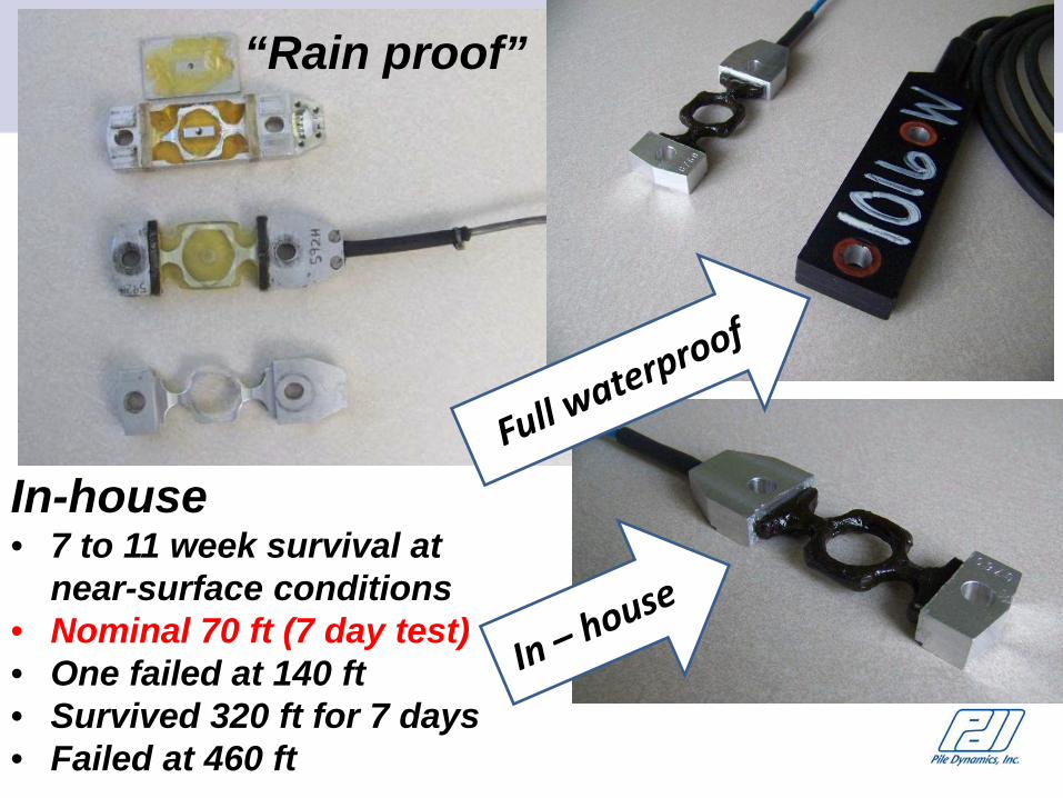
“Rain proof”
In-house• 7 to 11 week survival at
near-surface conditions• Nominal 70 ft (7 day test)• One failed at 140 ft• Survived 320 ft for 7 days• Failed at 460 ft
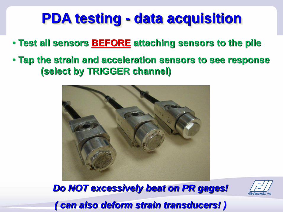
• Test all sensors BEFORE attaching sensors to the pile
• Tap the strain and acceleration sensors to see response (select by TRIGGER channel)
Do NOT excessively beat on PR gages!
( can also deform strain transducers! )
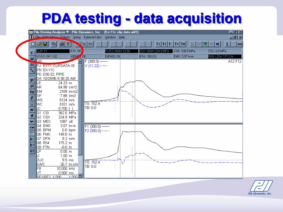
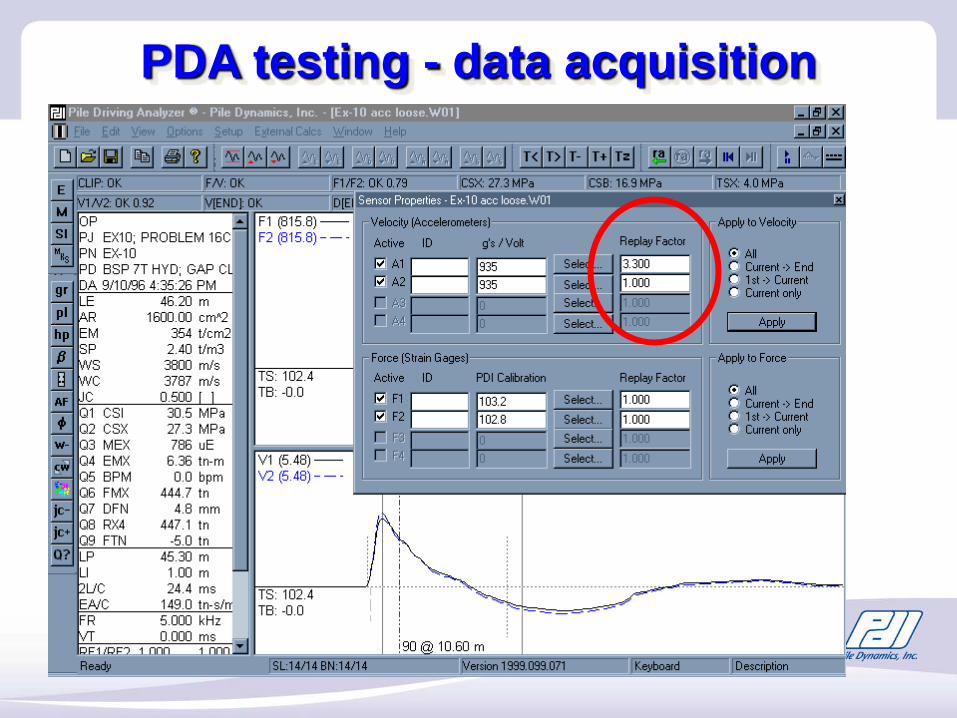
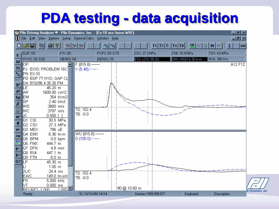
PDA testing - data acquisition
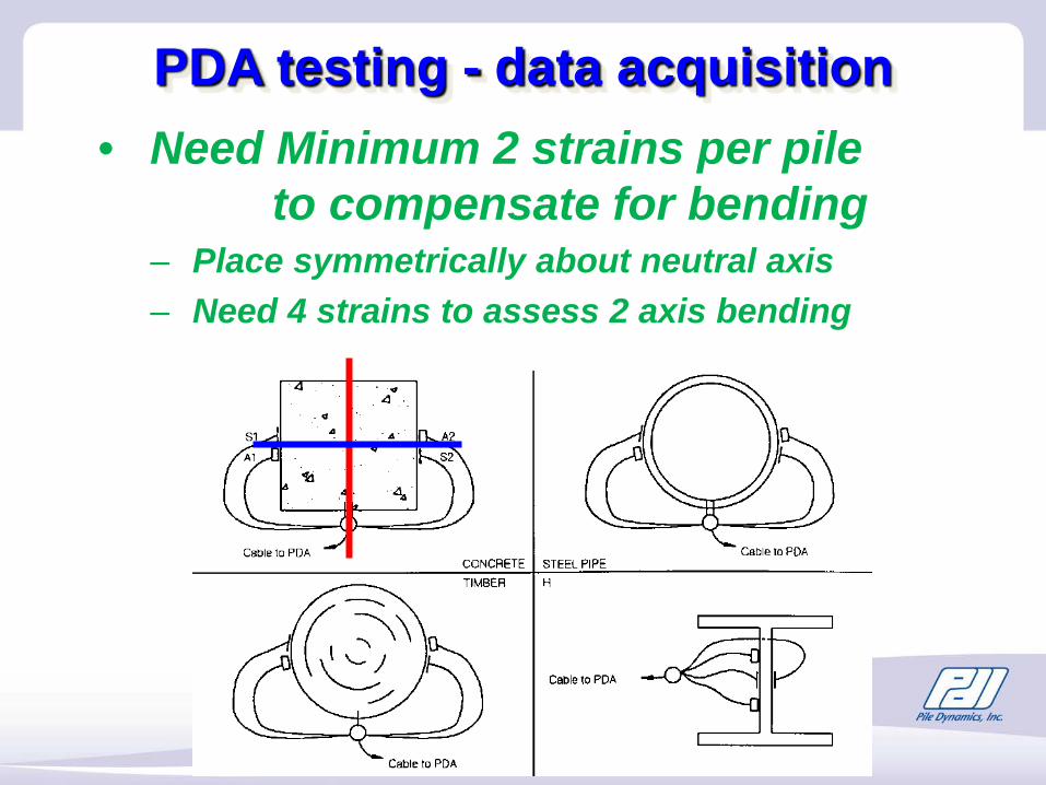
• Need Minimum 2 strains per pile to compensate for bending
– Place symmetrically about neutral axis– Need 4 strains to assess 2 axis bending
PDA testing - data acquisition
PDA testing - data acquisition
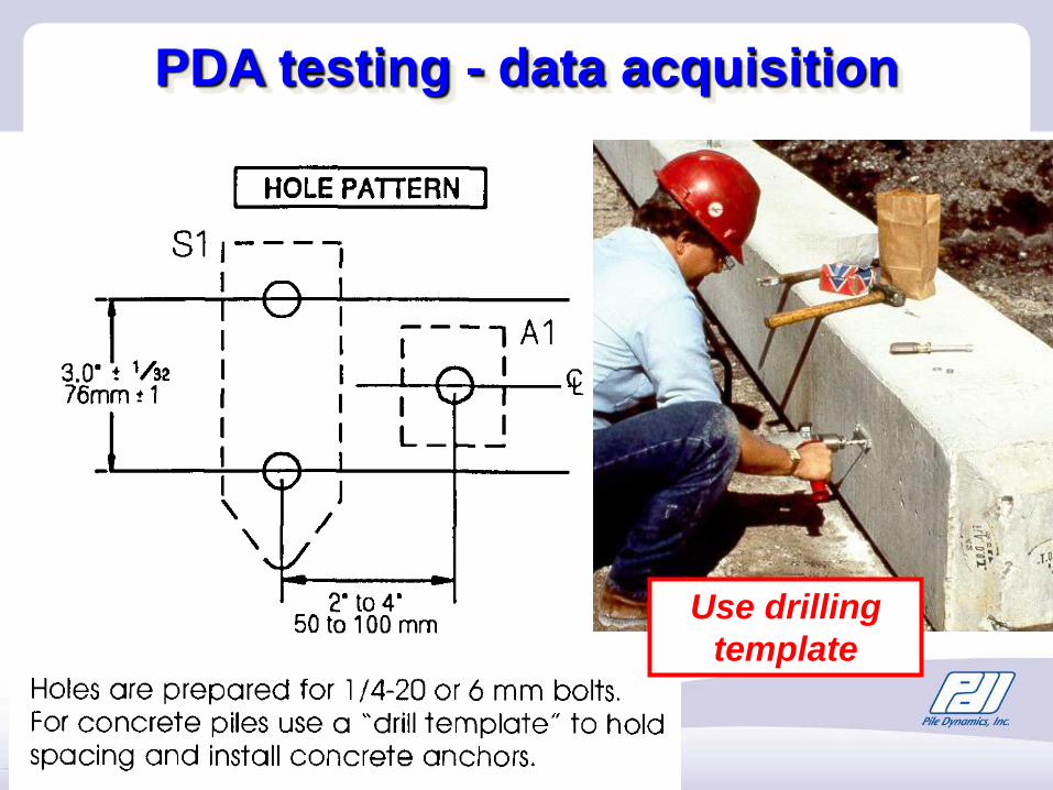
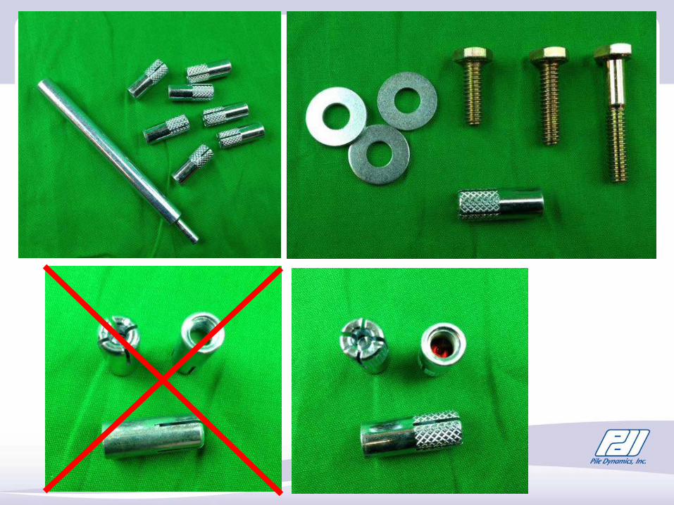
Use drilling template
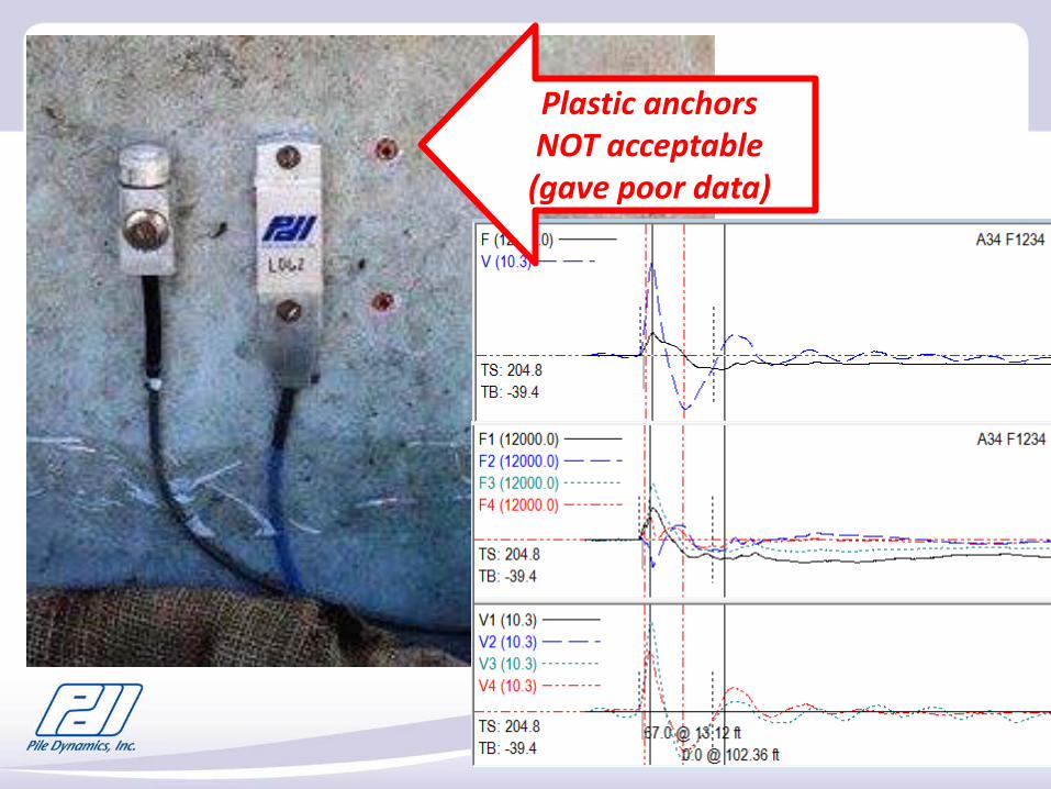
Plastic anchorsNOT acceptable(gave poor data)
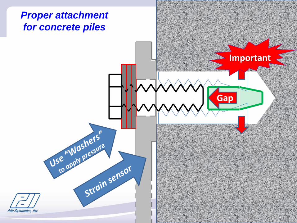
Proper attachment for concrete piles
Important
Gap
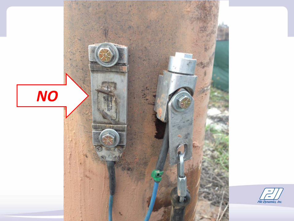
NO
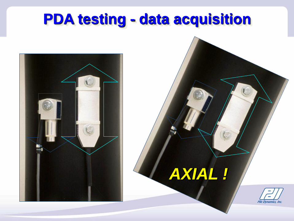
AXIAL !
PDA testing - data acquisition
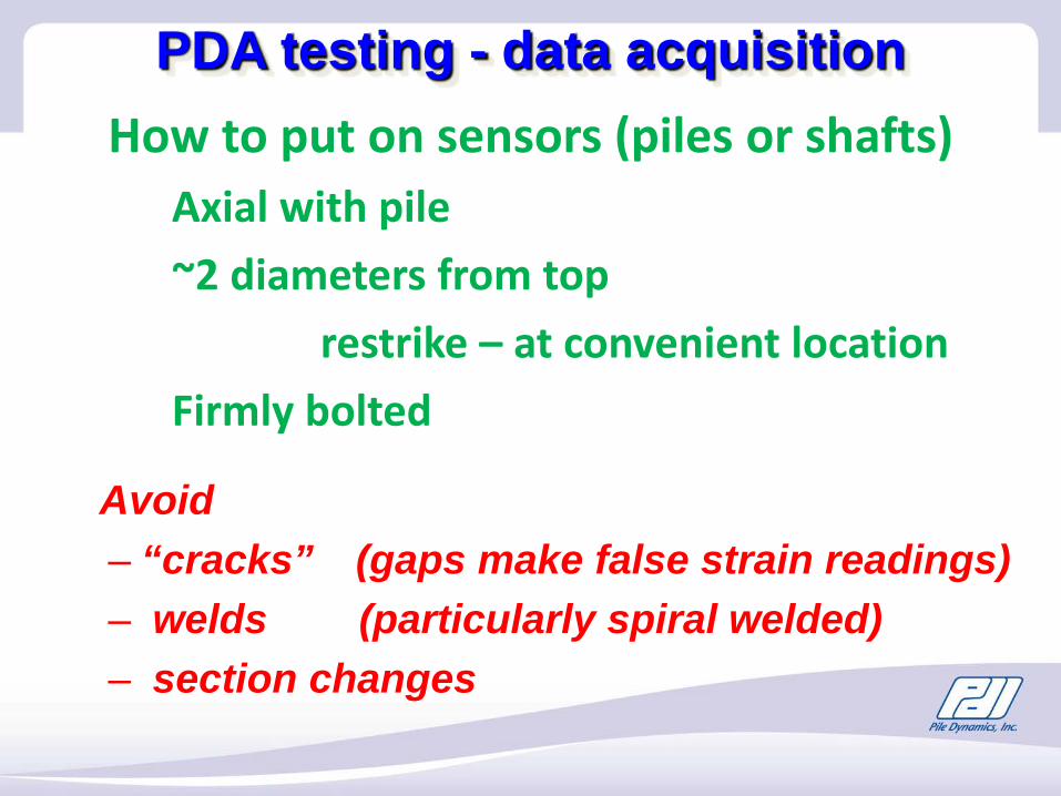
How to put on sensors (piles or shafts)Axial with pile~2 diameters from top
restrike – at convenient locationFirmly bolted
PDA testing - data acquisition
Avoid – “cracks” (gaps make false strain readings)– welds (particularly spiral welded)– section changes
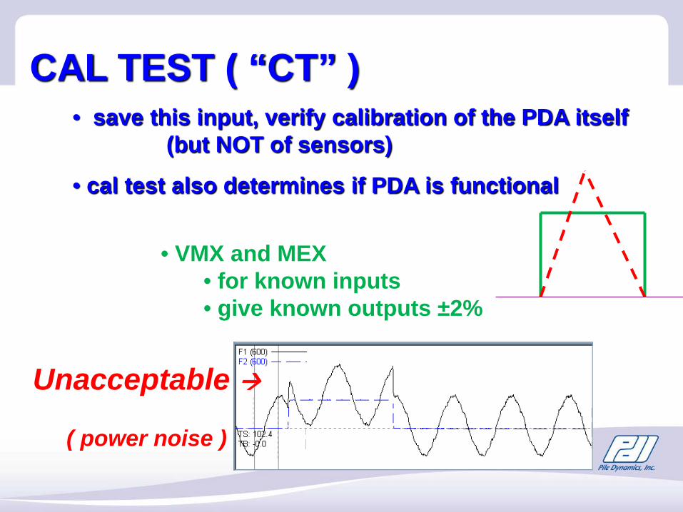
CAL TEST ( “CT” ) • save this input, verify calibration of the PDA itself
(but NOT of sensors)
• cal test also determines if PDA is functional
• VMX and MEX • for known inputs• give known outputs ±2%
Unacceptable
( power noise )
PAX - Balance
•PAX ( 8G ) have 10,000 µε total range (huge)
• PAX shows test range available (+3000 to -3000 µε)(PAK has 2000 µε range)
• PAX says “OK” then is OK to test
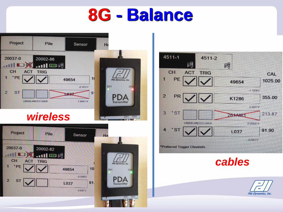
8G - Balance
wireless
cables
PDA testing - data acquisition
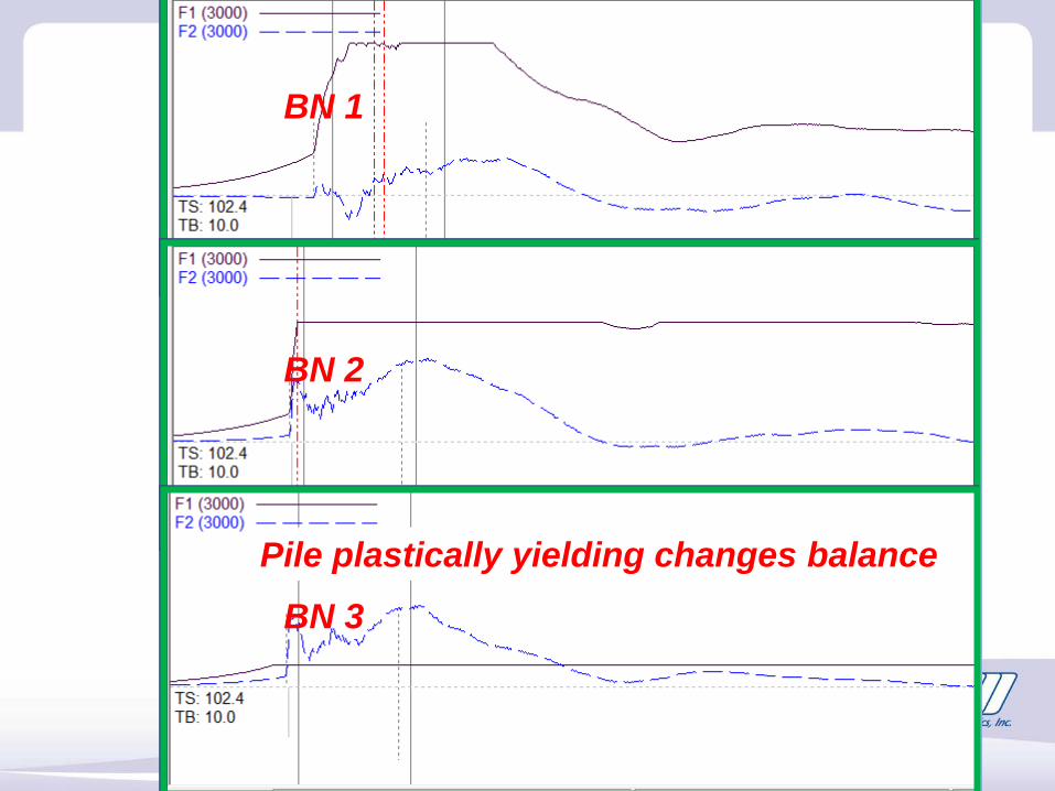
BN 1
BN 2
BN 3
Pile plastically yielding changes balance
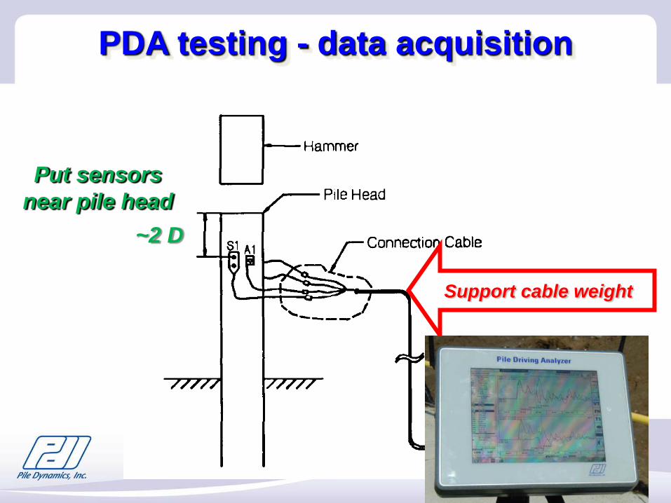
Put sensors near pile head
Support cable weight
~2 D
PDA testing - data acquisition
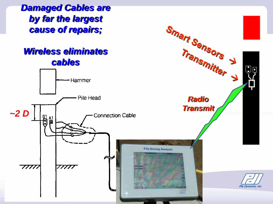
Damaged Cables are by far the largest cause of repairs;
Wireless eliminates cables
~2 DRadio
Transmit
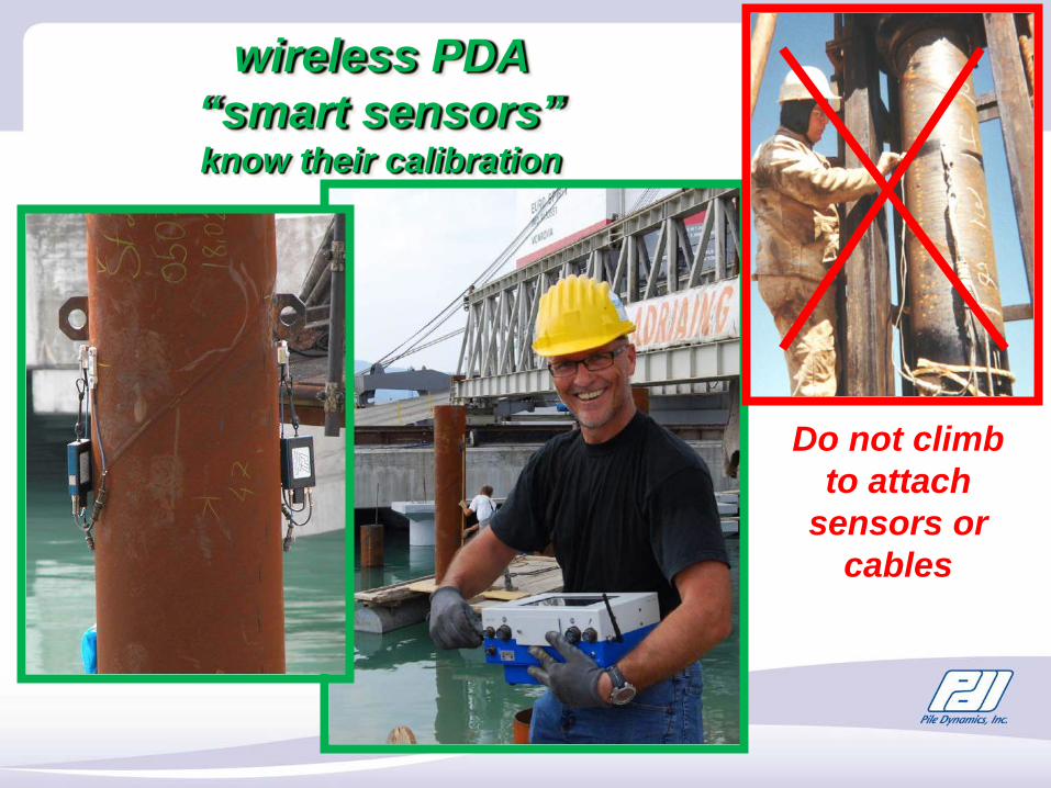
wireless PDA “smart sensors” know their calibration
Do not climb to attach
sensors or cables
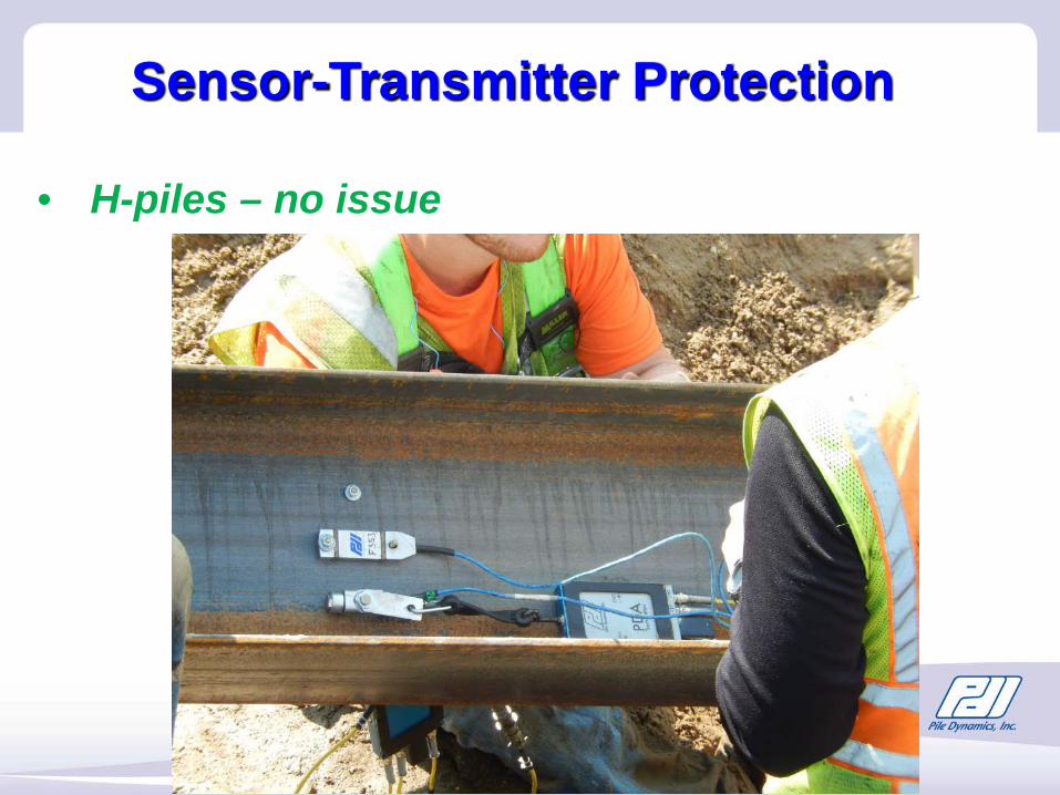
Sensor-Transmitter Protection
• H-piles – no issue
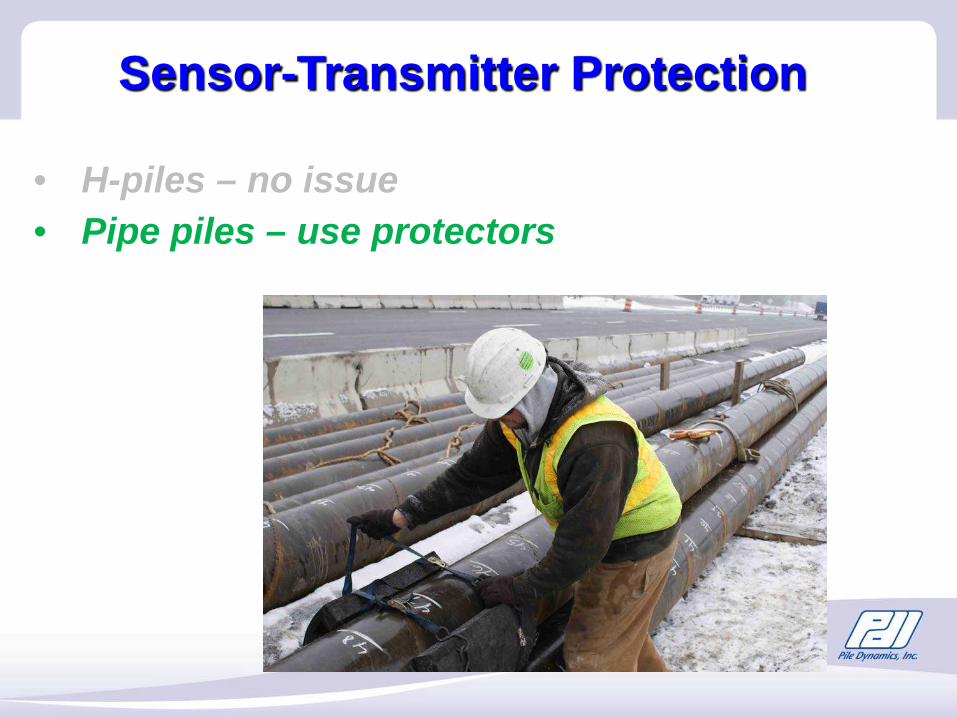
• H-piles – no issue• Pipe piles – use protectors
Sensor-Transmitter Protection
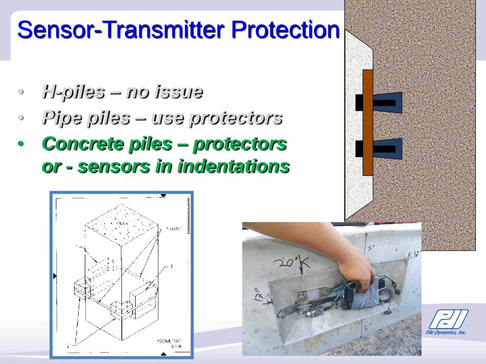
• H-piles – no issue• Pipe piles – use protectors• Concrete piles – protectors
or - sensors in indentations
Sensor-Transmitter Protection
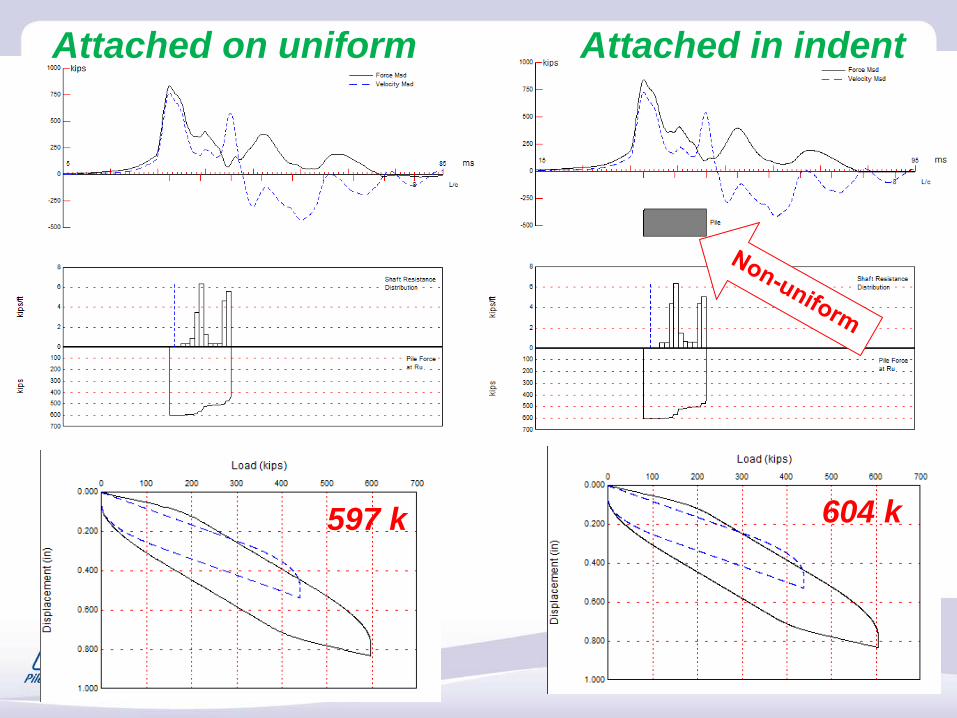
Attached on uniform Attached in indent
604 k597 k
Why Wireless?Eliminates cable
reliabilityaids site logistics easy clean up (no cable in the mud)
Allows attaching on ground speeds testing process properly attached
Easy to transport – very lightweight
PAX – allows 2 strain and 2 acceleration8G – allows up to 16 channels of data (any type)
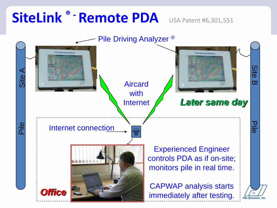
Pile
Site
APile
Site B
Pile Driving Analyzer ®
Aircardwith
Internet
Internet connection
Experienced Engineer controls PDA as if on-site; monitors pile in real time.
CAPWAP analysis starts immediately after testing.
Later same day
Office
SiteLink ® - Remote PDA USA Patent #6,301,551
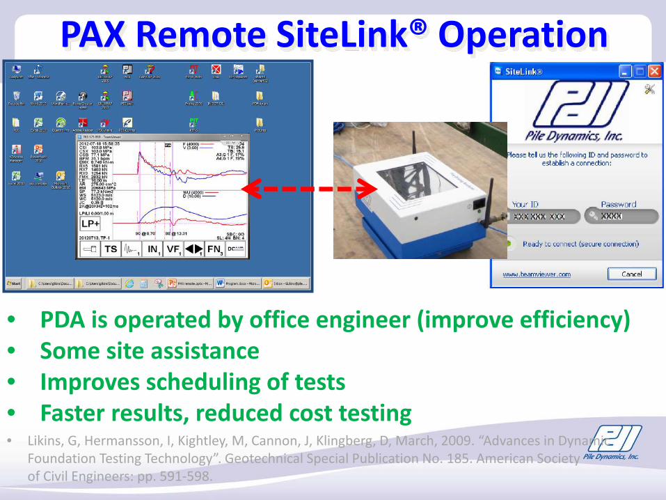
PAX Remote SiteLink® Operation
• PDA is operated by office engineer (improve efficiency)• Some site assistance• Improves scheduling of tests• Faster results, reduced cost testing• Likins, G, Hermansson, I, Kightley, M, Cannon, J, Klingberg, D, March, 2009. “Advances in Dynamic
Foundation Testing Technology”. Geotechnical Special Publication No. 185. American Society of Civil Engineers: pp. 591-598.
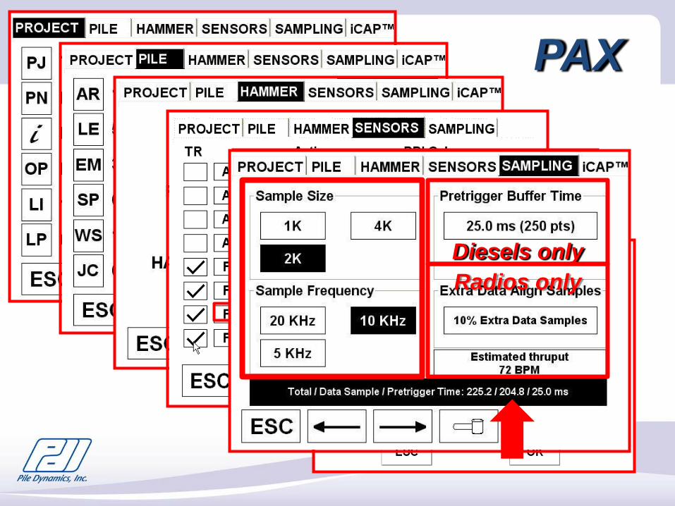
PAX
Diesels onlyRadios only
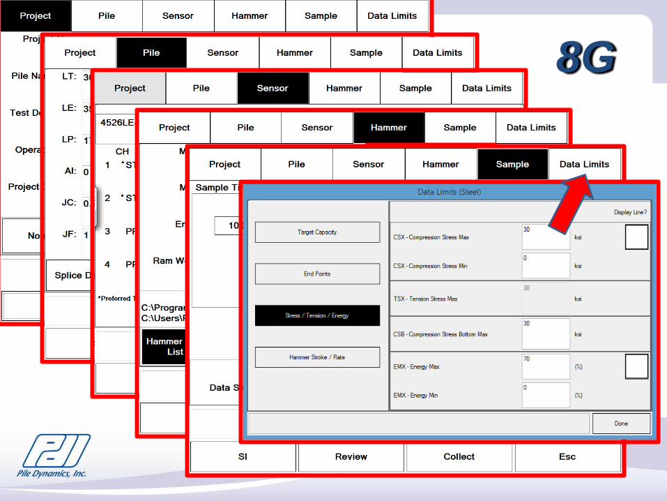
8G
35
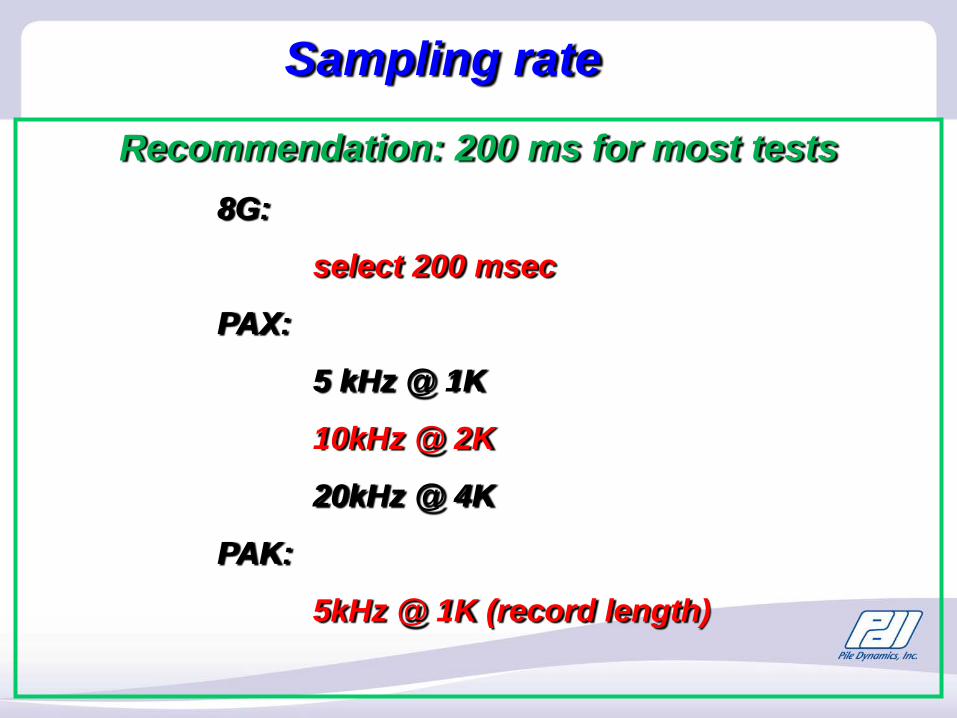
Sampling rate
Recommendation: 200 ms for most tests8G:
select 200 msec
PAX:
5 kHz @ 1K
10kHz @ 2K
20kHz @ 4K
PAK:
5kHz @ 1K (record length)
Minimum 2 strains per pile (symmetrical)to compensate bending
PDA testing - data acquisition
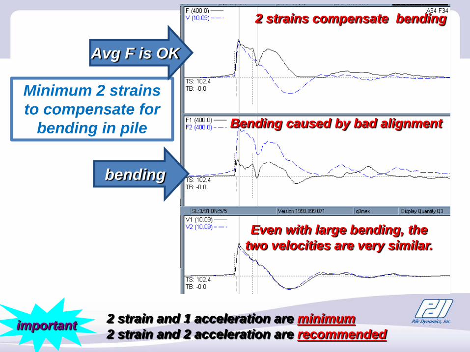
2 strains compensate bending
Bending caused by bad alignment
Even with large bending, the two velocities are very similar.
2 strain and 1 acceleration are minimum2 strain and 2 acceleration are recommendedimportant
Minimum 2 strains to compensate for
bending in pile
bending
Avg F is OK
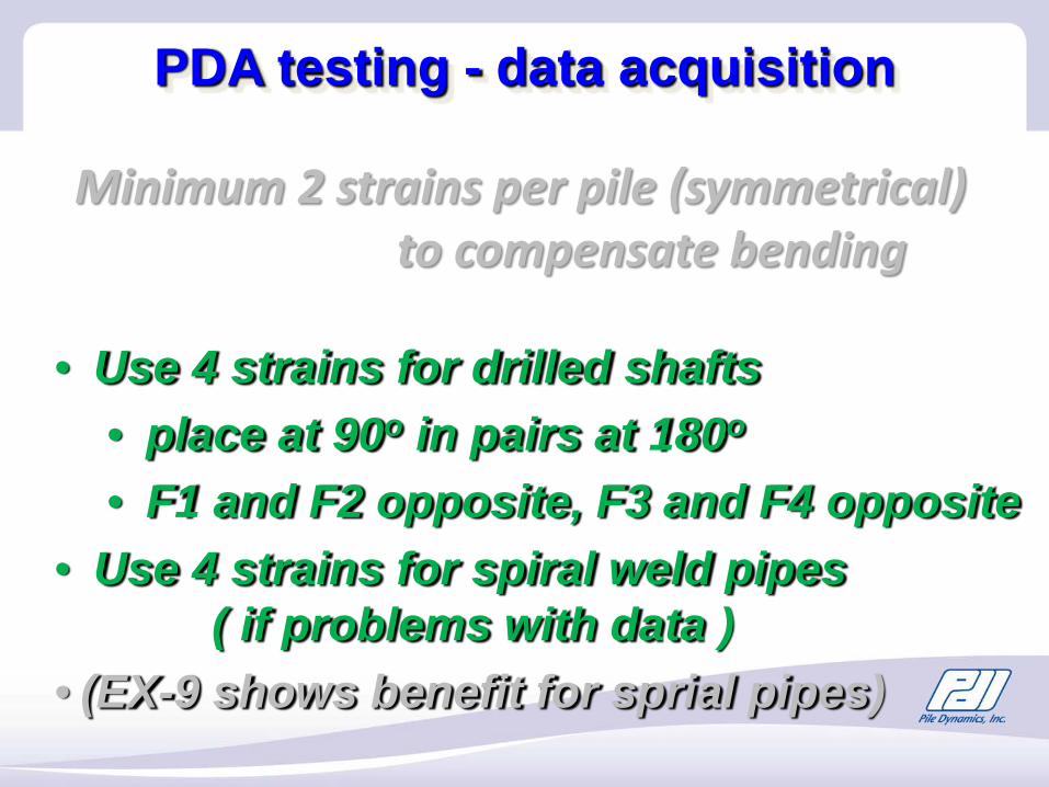
Minimum 2 strains per pile (symmetrical)to compensate bending
• Use 4 strains for drilled shafts • place at 90o in pairs at 180o
• F1 and F2 opposite, F3 and F4 opposite• Use 4 strains for spiral weld pipes
( if problems with data )• (EX-9 shows benefit for sprial pipes)
PDA testing - data acquisition
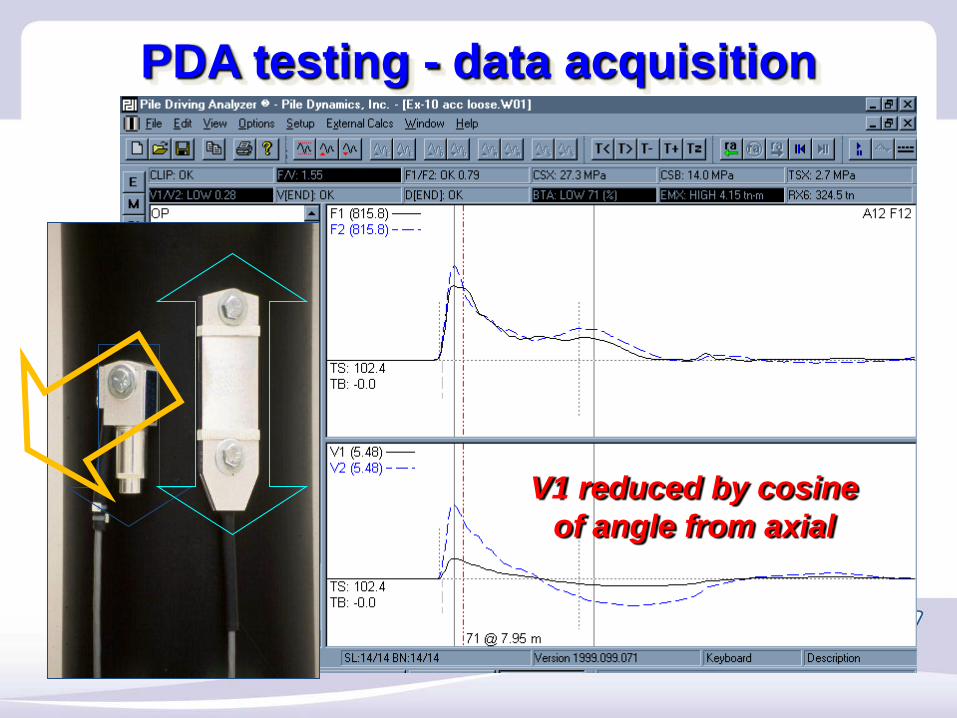
V1 reduced by cosine of angle from axial
PDA testing - data acquisition
PDA testing - data acquisition
PDA testing - data acquisition
PDA testing - data acquisition
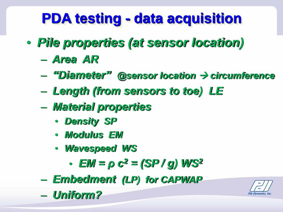
• Pile properties (at sensor location)– Area AR– “Diameter” @sensor location circumference– Length (from sensors to toe) LE– Material properties
• Density SP• Modulus EM• Wavespeed WS
• EM = ρ c2 = (SP / g) WS2
– Embedment (LP) for CAPWAP– Uniform?
PDA testing - data acquisition
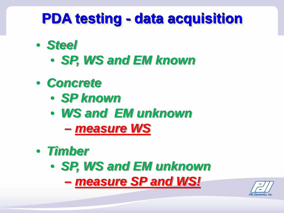
• Steel• SP, WS and EM known
• Concrete• SP known• WS and EM unknown
– measure WS
• Timber• SP, WS and EM unknown
– measure SP and WS!
PDA testing - data acquisition
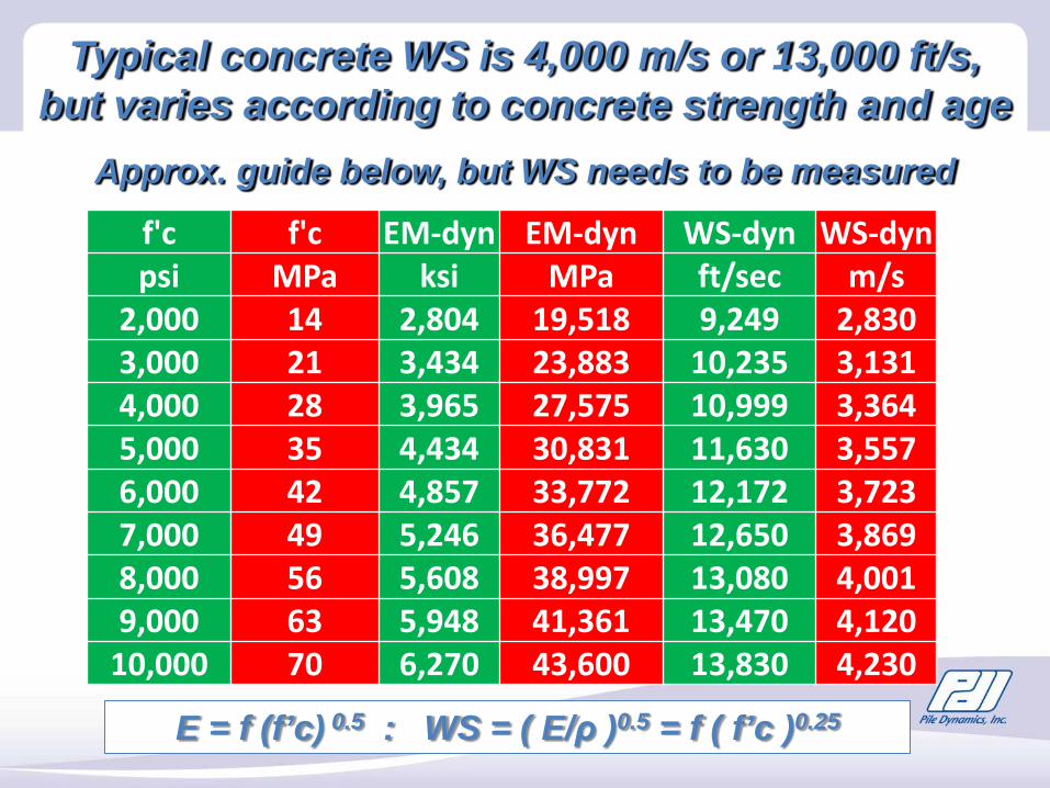
Typical concrete WS is 4,000 m/s or 13,000 ft/s, but varies according to concrete strength and age
Approx. guide below, but WS needs to be measured
E = f (f’c) 0.5 : WS = ( E/ρ )0.5 = f ( f’c )0.25
f'c f'c EM-dyn EM-dyn WS-dyn WS-dynpsi MPa ksi MPa ft/sec m/s
2,000 14 2,804 19,518 9,249 2,8303,000 21 3,434 23,883 10,235 3,1314,000 28 3,965 27,575 10,999 3,3645,000 35 4,434 30,831 11,630 3,5576,000 42 4,857 33,772 12,172 3,7237,000 49 5,246 36,477 12,650 3,8698,000 56 5,608 38,997 13,080 4,0019,000 63 5,948 41,361 13,470 4,120
10,000 70 6,270 43,600 13,830 4,230
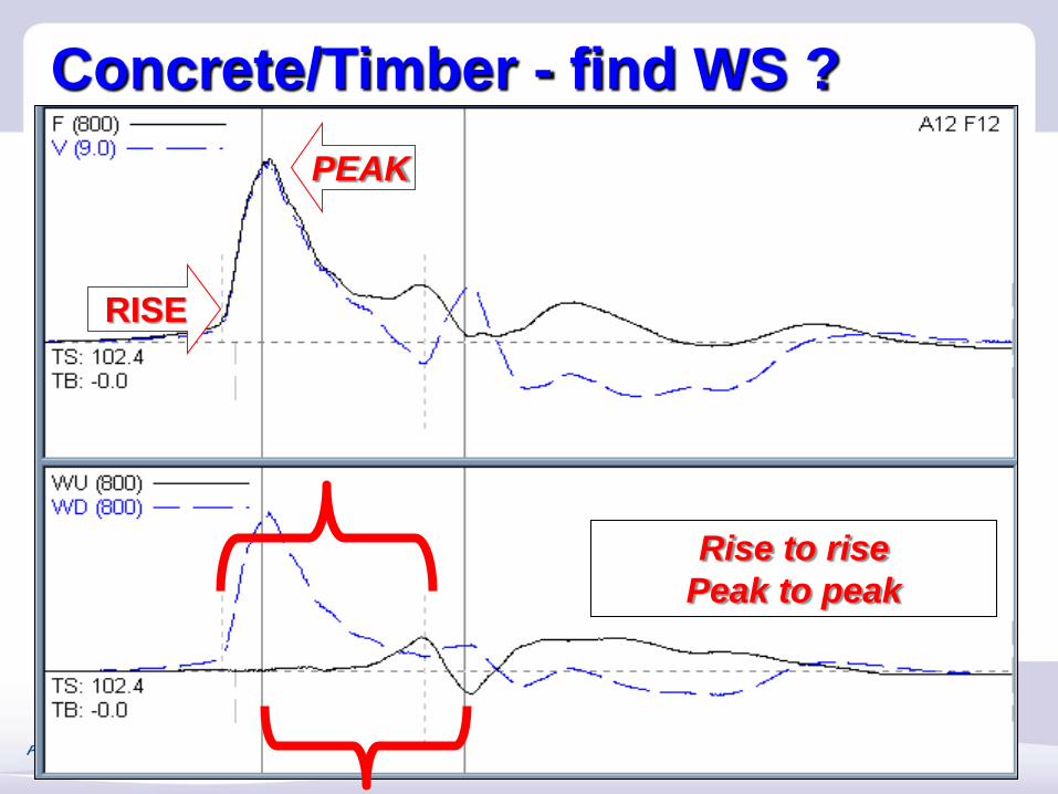
Concrete/Timber - find WS ?
Rise to rise Peak to peak
RISE
PEAK
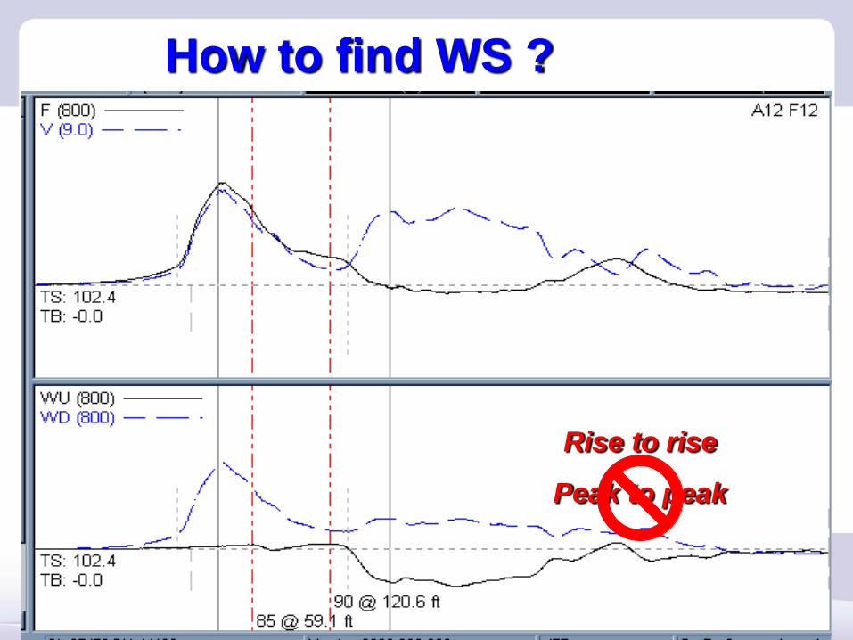
How to find WS ?
Rise to rise
Peak to peak
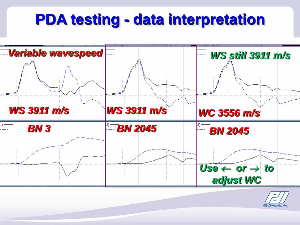
WS 3911 m/s
BN 3
WS 3911 m/s
BN 2045
Variable wavespeed
Use ← or → to adjust WC
WC 3556 m/s
BN 2045
WS still 3911 m/s
PDA testing - data interpretation
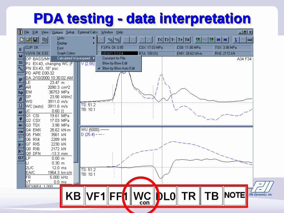
PDA testing - data interpretation
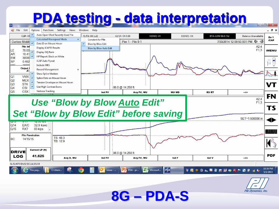
PDA testing - data interpretation
8G – PDA-S
Use “Blow by Blow Auto Edit”Set “Blow by Blow Edit” before saving
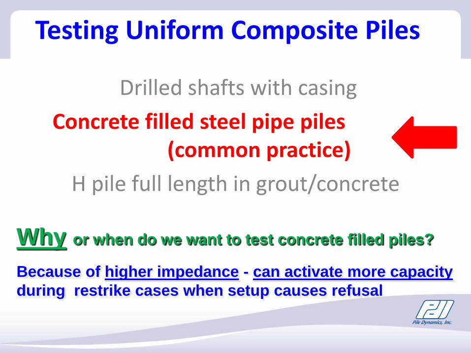
Drilled shafts with casing Concrete filled steel pipe piles
(common practice)H pile full length in grout/concrete
Testing Uniform Composite Piles
Because of higher impedance - can activate more capacityduring restrike cases when setup causes refusal
Why or when do we want to test concrete filled piles?
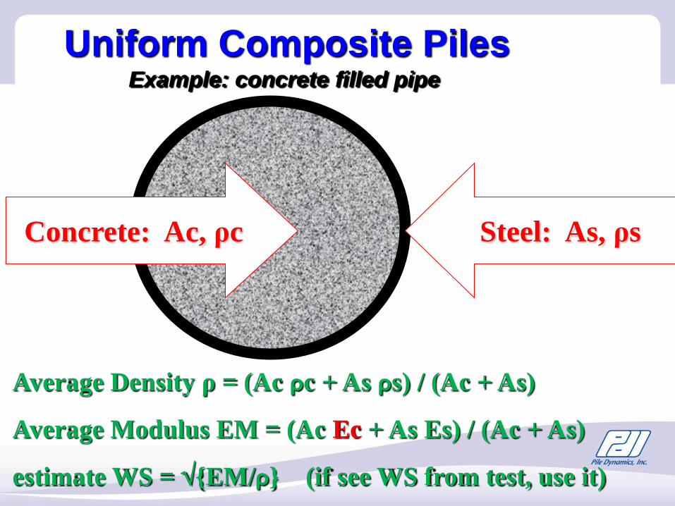
Concrete: Ac, ρc Steel: As, ρs
Uniform Composite Piles
Average Density ρ = (Ac ρc + As ρs) / (Ac + As)
Average Modulus EM = (Ac Ec + As Es) / (Ac + As)
estimate WS = √{EM/ρ} (if see WS from test, use it)
Example: concrete filled pipe

• Concrete strain = Steel strain this is required !
•if high percent steel, attach to steel “windows” make significant (bad) stress concentration effect (do not make windows)
•if low percent steel, (use “windows”) attach to concrete
EAsteel / EAtotal < 10%
Important
Protect pile top with plywood cushion
Concrete filled pipeMust hit thru concrete
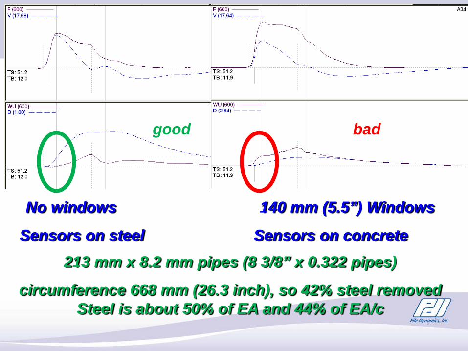
213 mm x 8.2 mm pipes (8 3/8” x 0.322 pipes)
circumference 668 mm (26.3 inch), so 42% steel removed Steel is about 50% of EA and 44% of EA/c
No windows 140 mm (5.5”) Windows
Sensors on steel Sensors on concrete
badgood
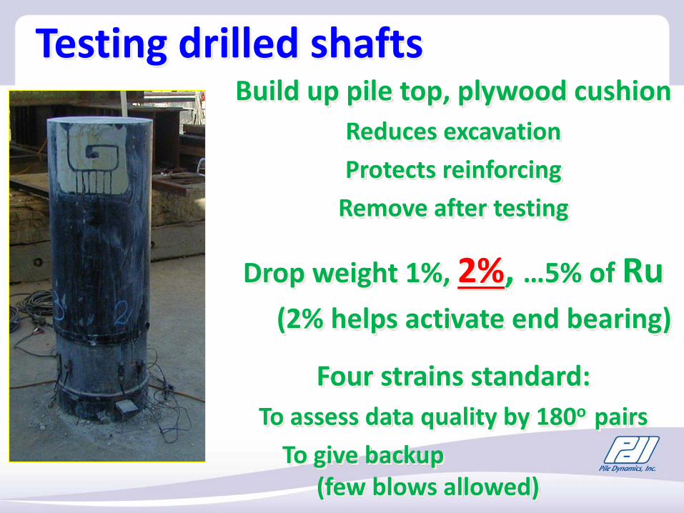
Testing drilled shaftsBuild up pile top, plywood cushion
Reduces excavationProtects reinforcing
Remove after testing
Drop weight 1%, 2%, …5% of Ru(2% helps activate end bearing)
Four strains standard: To assess data quality by 180o pairs
To give backup (few blows allowed)
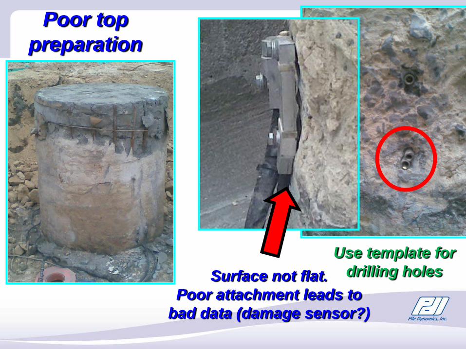
Poor top preparation
Use template for drilling holesSurface not flat.
Poor attachment leads to bad data (damage sensor?)
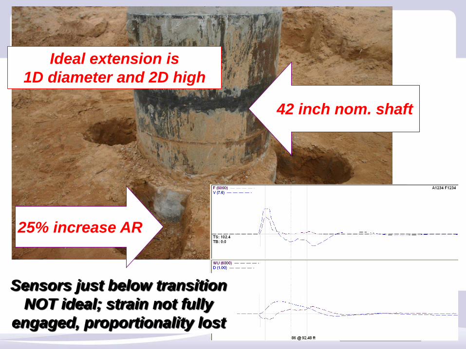
42 inch nom. shaft
25% increase AR
Sensors just below transition NOT ideal; strain not fully
engaged, proportionality lost
Ideal extension is 1D diameter and 2D high
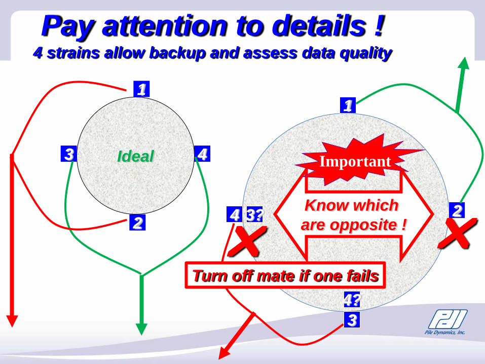
Ideal
2
3 4
1
24
3
1
4?
3? Know which are opposite !
Pay attention to details ! 4 strains allow backup and assess data quality
Turn off mate if one fails
Important
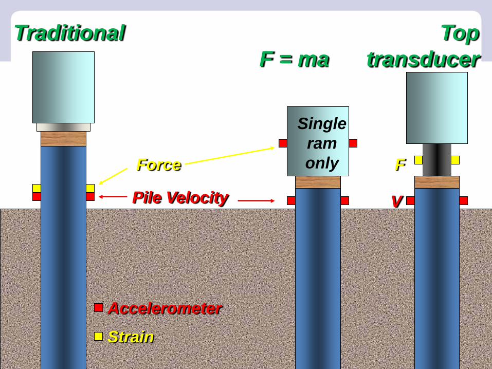
Strain
Accelerometer
Pile Velocity
Force
TraditionalF = ma
Top transducer
F
V
Single ram only
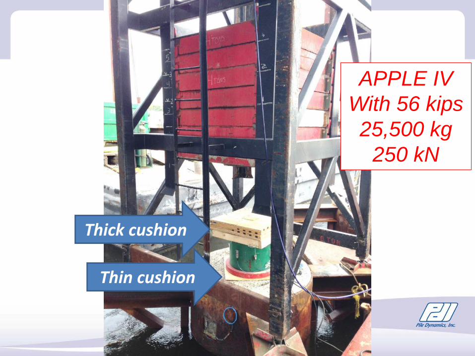
Thick cushion
APPLE IVWith 56 kips25,500 kg
250 kN
Thin cushion


![arXiv:math/9712210v1 [math.GT] 1 Dec 1997](https://static.fdocument.org/doc/165x107/621d7e785e5e2077ac25333d/arxivmath9712210v1-mathgt-1-dec-1997.jpg)