
Page 2 Practice Paper EE D Chapter 1 - Vidyarthiplus
68
Transcript of Page 2 Practice Paper EE D Chapter 1 - Vidyarthiplus

Page 2 Practice Paper EE_D Chapter 1
MCQ 1.4 The value of 2
cosi z
zdz
11
c
2ππ−
# around a rectangle with vertices at 2 , 2i i! !− is
(A) 6 (B) i e2
(C) 8 (D) 0
SOL 1.4 Option (D) is correct.
Let, I 2
cosi z
zdz11
1
c
2ππ=
−#
2.2
cosi z z
zdz1
11
11
cπ
π=−−+b l#
Or I cos cosi z
zzzdz
41
1 10
cπ
π π=−−+
=a k#
MCQ 1.5 Resolution of 4-bit analog to digital converter in percent is
(A) 6.25% (B) 6.67%
(C) 12.5% (D) 25%
SOL 1.5 Option (B) is correct.
% Resolution 1002 1
1n #=−
100 6.67%2 1
14 #=−
=
MCQ 1.6 A logical function of four variable is given as
( , , , )f A B C D ( )( )A BC B CD= + +
The function as a sum of product is
(A) A BC ACD BCD+ + +
(B) A BC ACD BCD+ + +
(C) AB BC ACD BCD+ + +
(D) AB AB ACD BCD+ + +
SOL 1.6 Option (C) is correct.
f ( ) ( )A BC B A BC CD= + + +
AB BC ACD BCD= + + +
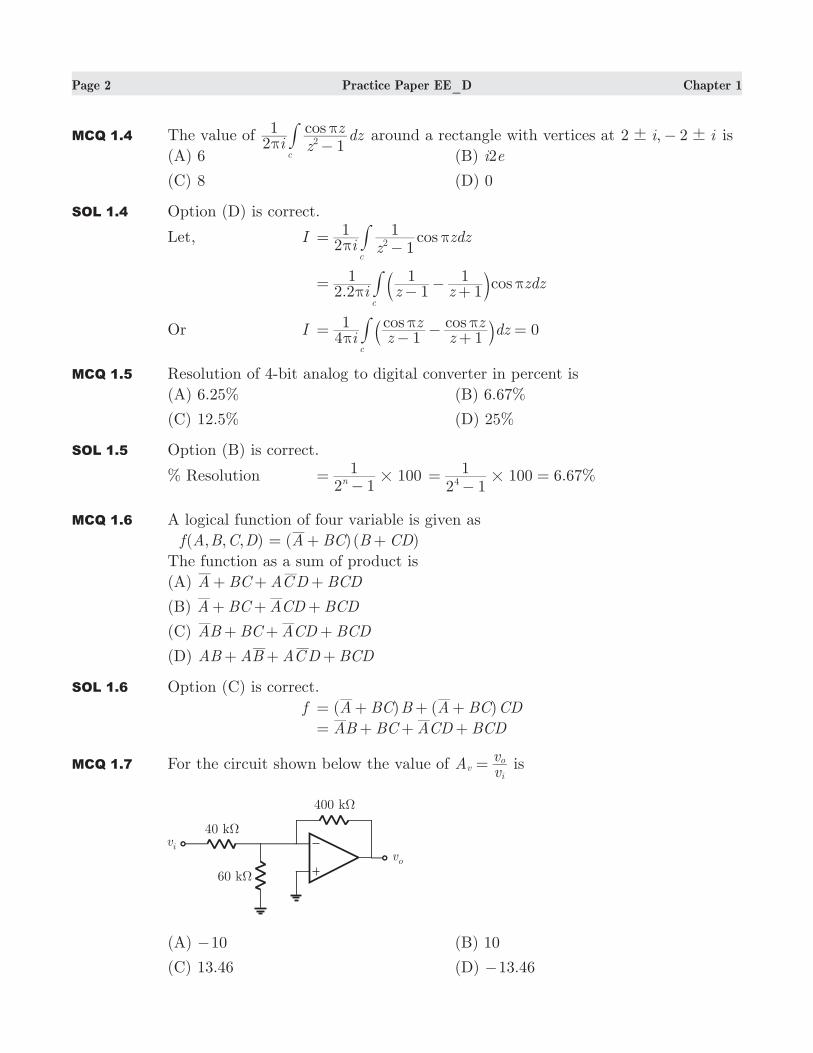
MCQ 1.7 For the circuit shown below the value of Avv
vi
o= is
(A) 10− (B) 10
(C) 13.46 (D) 13.46−
Page 3 Practice Paper EE_D Chapter 1
SOL 1.7 Option (A) is correct.
The noninverting terminal is at ground level. Thus inverting terminal is also at
virtual ground. There will not be any current in 60 kΩ.
Av 1040400=− =−
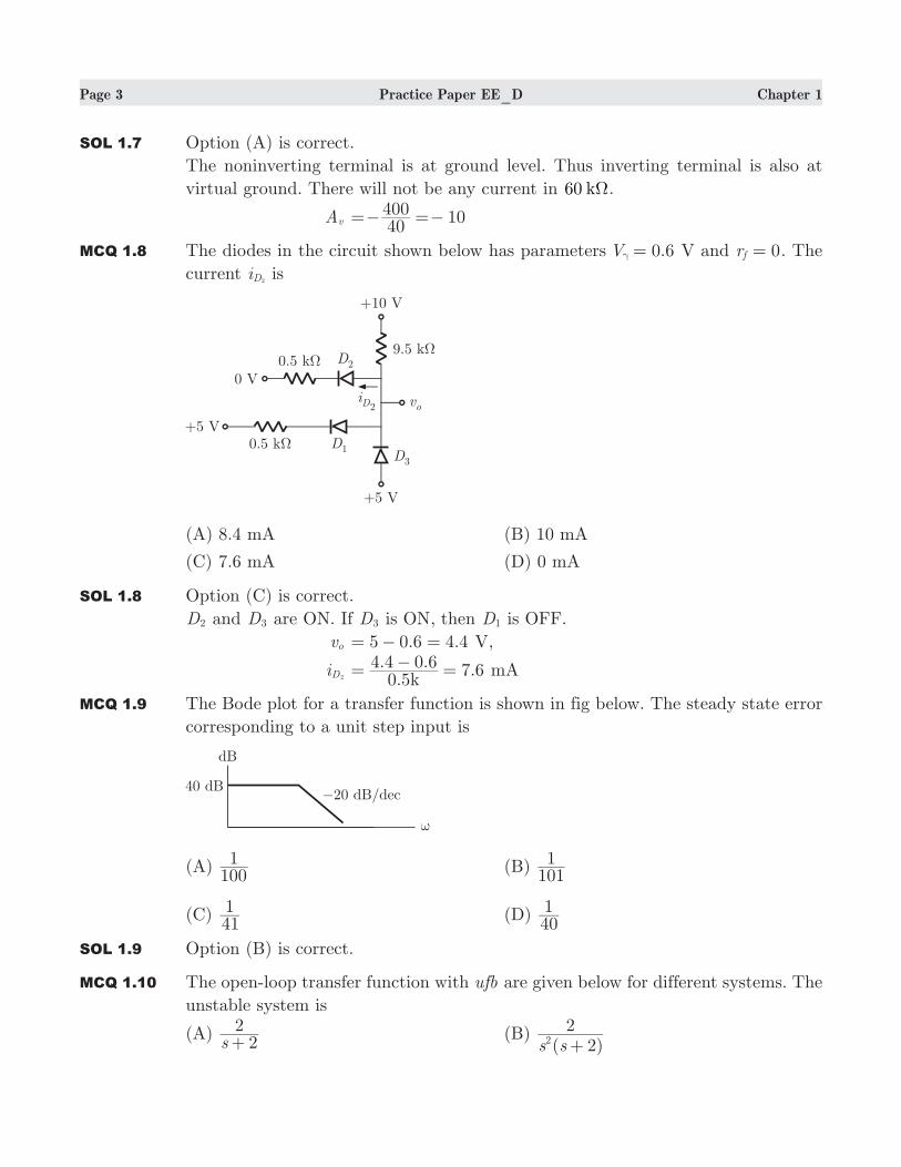
MCQ 1.8 The diodes in the circuit shown below has parameters 0.6V =γ V and 0rf = . The
current iD2 is
(A) 8.4 mA (B) 10 mA
(C) 7.6 mA (D) 0 mA
SOL 1.8 Option (C) is correct.
D2 and D3 are ON. If D3 is ON, then D1 is OFF.
vo 5 0.6 4.4= − = V,
iD2
.. . 7.60 5
4 4 0 6k
= − = mA
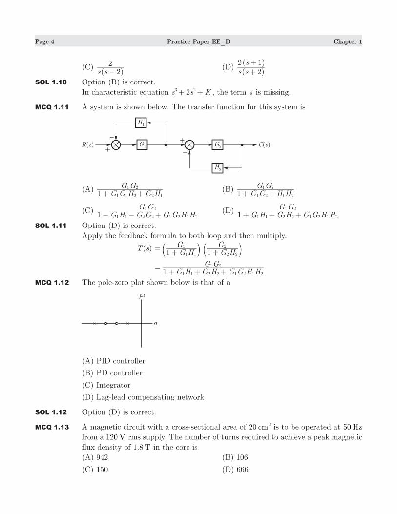
MCQ 1.9 The Bode plot for a transfer function is shown in fig below. The steady state error
corresponding to a unit step input is
(A) 1001 (B)
1011
(C) 411 (D)
401
SOL 1.9 Option (B) is correct.
MCQ 1.10 The open-loop transfer function with ufb are given below for different systems. The
unstable system is
(A) s 2
2+
(B) ( )s s 2
22 +
Page 4 Practice Paper EE_D Chapter 1
(C) ( )s s 2
2−
(D) ( )( )s s
s
22 1+
+
SOL 1.10 Option (B) is correct.
In characteristic equation 2s s K3 2+ + , the term s is missing.
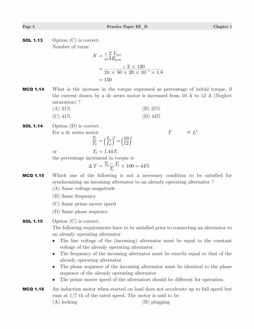
MCQ 1.11 A system is shown below. The transfer function for this system is
(A) G G H G HG G
1 1 1 2 2 1
1 2
+ + (B)
G G H HG G
1 1 2 1 2
1 2
+ +
(C) G H G G G G H H
G G1 1 1 2 2 1 2 1 2
1 2
− − + (D)
G H G H G G H HG G
1 1 1 2 2 1 2 1 2
1 2
+ + +
SOL 1.11 Option (D) is correct.
Apply the feedback formula to both loop and then multiply.
( )T s G HG
1 1 1
1=+b l G H
G1 2 2
2
+b l
G H G H G G H HG G
1 1 1 2 2 1 2 1 2
1 2=+ + +
MCQ 1.12 The pole-zero plot shown below is that of a
(A) PID controller
(B) PD controller
(C) Integrator
(D) Lag-lead compensating network
SOL 1.12 Option (D) is correct.
MCQ 1.13 A magnetic circuit with a cross-sectional area of cm20 2 is to be operated at 0 Hz5
from a 120 V rms supply. The number of turns required to achieve a peak magnetic
flux density of 1.8 T in the core is
(A) 942 (B) 106
(C) 150 (D) 666
Page 5 Practice Paper EE_D Chapter 1
SOL 1.13 Option (C) is correct.
Number of turns
N ABV2
peak
rms
ω=
.2 50 20 10 1 8
2 1204
# # # #
#
π= −
150=
MCQ 1.14 What is the increase in the torque expressed as percentage of initial torque, if
the current drawn by a dc series motor is increased from 10 A to 12 A (Neglect
saturation) ?
(A) 21% (B) 25%
(C) 41% (D) 44%
SOL 1.14 Option (D) is correct.
For a dc series motor T Ia2
\
TT1
2 II
1210
2
1
a
a2 2
= =b bl lor T2 . T1 44 1=
the percentage increment in torque is
TT 100 44%T
T T1
2 1#=
−=
MCQ 1.15 Which one of the following is not a necessary condition to be satisfied for
synchronizing an incoming alternator to an already operating alternator ?
(A) Same voltage magnitude
(B) Same frequency
(C) Same prime mover speed
(D) Same phase sequence
SOL 1.15 Option (C) is correct.
The following requirements have to be satisfied prior to connecting an alternator to
an already operating alternator
• The line voltage of the (incoming) alternator must be equal to the constant
voltage of the already operating alternator.
• The frequency of the incoming alternator must be exactly equal to that of the
already operating alternator
• The phase sequence of the incoming alternator must be identical to the phase
sequence of the already operating alternator
• The prime mover speed of the alternators should be different for operation.
MCQ 1.16 An induction motor when started on load does not accelerate up to full speed but
runs at 1/7 th of the rated speed. The motor is said to be
(A) locking (B) plugging
Page 6 Practice Paper EE_D Chapter 1
(C) crawling (D) cogging
SOL 1.16 Option (C) is correct.
A cage motor shows peculiar behavior at starting because the motor has a certain
relationship between the number of poles and the stator and rotor slots. For some
ratio of rotor-to-stator slots, the machine may run stably at a low speed(1/7 of the
rated speed). This phenomena is called crawling.
MCQ 1.17 In a stepper motor, the detent torque means
(A) minimum of the static torque with the phase winding excited
(B) maximum of the static torque with the phase winding excited
(C) minimum of the static torque with the phase winding unexcited
(D) maximum of the static torque with the phase winding unexcited
SOL 1.17 Option (D) is correct.
Detent torque/Restraining toque:
The residual magnetism in the permanent magnetic material produced.
The detent torque is defined as the maximum load torque that can be applied to
the shaft of an unexcited motor without causing continuous rotation. In case the
motor is unexcited.
MCQ 1.18 Consider a discrete-time system S whose response to a complex exponential input
e /2j nπ is specified as
:S e /2jπ e 3 /2j n&
π
The system is
(A) definitely LTI (B) definitely not LTI
(C) may be LTI (D) information is not sufficient
SOL 1.18 Option (B) is correct.
The input e /2j nπ must produce the output is the form Ae /2j mπ . The output in this
case is e 3 /2j nπ . This violates the Eigen function property of LTI system. Therefore,
S is definitely not LTI system.
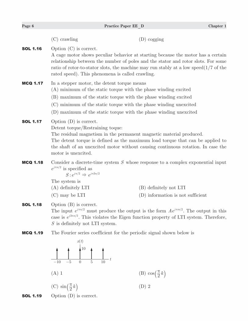
MCQ 1.19 The Fourier series coefficient for the periodic signal shown below is
(A) 1 (B) cos k2πa k
(C) sin k2πa k (D) 2
SOL 1.19 Option (D) is correct.
Page 7 Practice Paper EE_D Chapter 1
[ ]X k ( ) ,T
A t e dtTA1
/
/jk
T
T
2
2
δ= =ω−
−#
10A = , 5T = , [ ] 2X k =
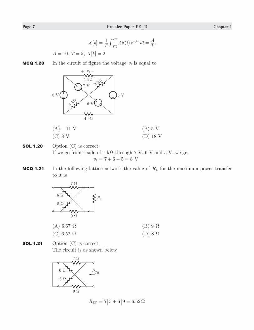
MCQ 1.20 In the circuit of figure the voltage v1 is equal to
(A) 11− V (B) 5 V
(C) 8 V (D) 18 V
SOL 1.20 Option (C) is correct.
If we go from +side of 1 kΩ through 7 V, 6 V and 5 V, we get
v1 7 6 5 8= + − = V
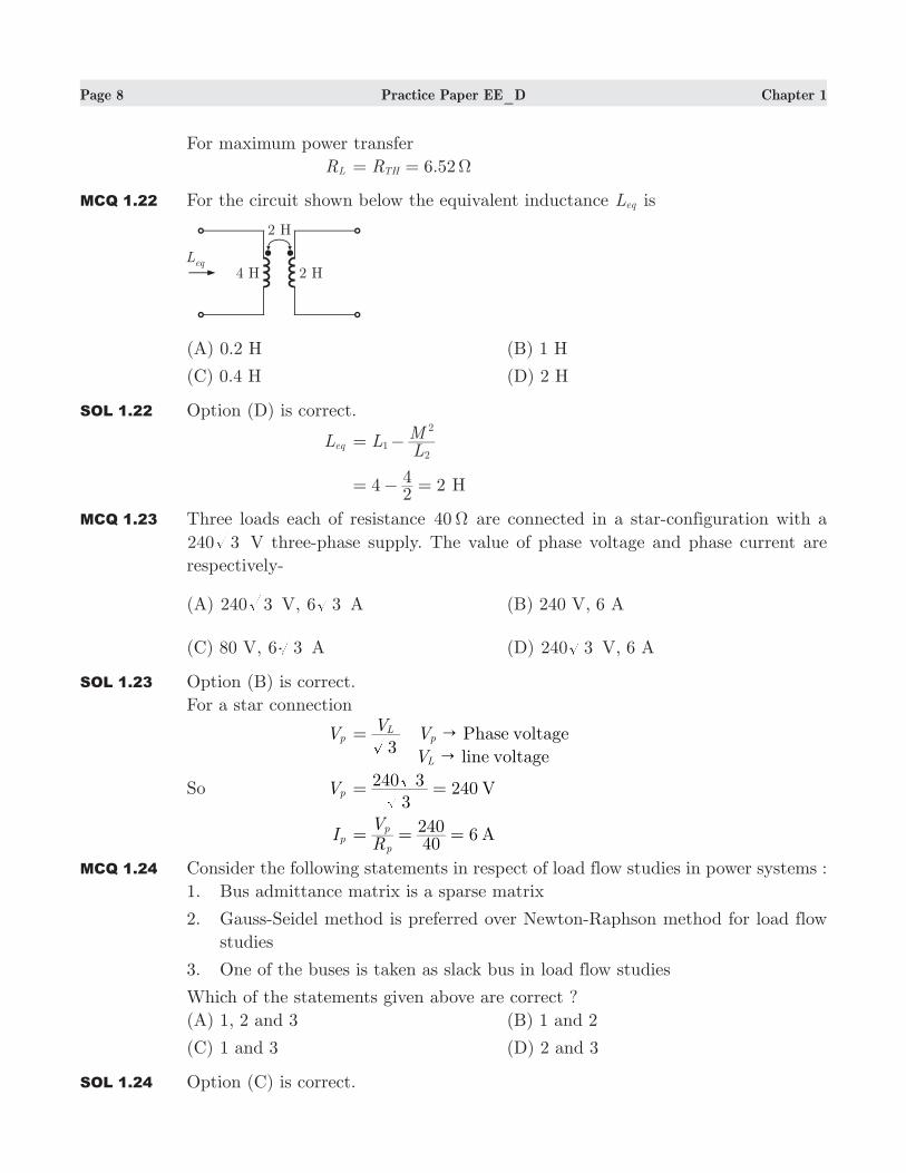
MCQ 1.21 In the following lattice network the value of RL for the maximum power transfer
to it is
(A) 6.67 Ω (B) 9 Ω
(C) 6.52 Ω (D) 8 Ω
SOL 1.21 Option (C) is correct.
The circuit is as shown below
RTH 7 9 6.525 6 Ω= + =
Page 8 Practice Paper EE_D Chapter 1
For maximum power transfer
RL 6.52RTH Ω= =
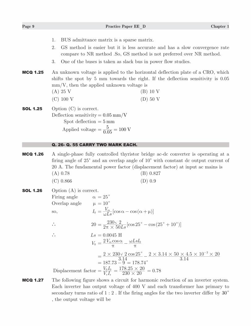
MCQ 1.22 For the circuit shown below the equivalent inductance Leq is
(A) 0.2 H (B) 1 H
(C) 0.4 H (D) 2 H
SOL 1.22 Option (D) is correct.
Leq LLM
12
2
= −
4 224= − = H
MCQ 1.23 Three loads each of resistance 40Ω are connected in a star-configuration with a
240 3 V three-phase supply. The value of phase voltage and phase current are
respectively-
(A) 240 3 V, 6 3 A (B) 240 V, 6 A
(C) 80 V, 6 3 A (D) 240 3 V, 6 A
SOL 1.23 Option (B) is correct.
For a star connection
Vp V
3L= V Phase voltagep"
V line voltageL"
So Vp 2403
240 3 V= =
Ip 6RV
40240 A
p
p= = =
MCQ 1.24 Consider the following statements in respect of load flow studies in power systems :
1. Bus admittance matrix is a sparse matrix
2. Gauss-Seidel method is preferred over Newton-Raphson method for load flow
studies
3. One of the buses is taken as slack bus in load flow studies
Which of the statements given above are correct ?
(A) 1, 2 and 3 (B) 1 and 2
(C) 1 and 3 (D) 2 and 3
SOL 1.24 Option (C) is correct.
Page 9 Practice Paper EE_D Chapter 1
1. BUS admittance matrix is a sparse matrix.
2. GS method is easier but it is less accurate and has a slow convergence rate
compare to NR method .So, GS method is not preferred over NR method.
3. One of the buses is taken as slack bus in power flow studies.
MCQ 1.25 An unknown voltage is applied to the horizontal deflection plate of a CRO, which
shifts the spot by 5 mm towards the right. If the deflection sensitivity is 0.05
mm/V, then the applied unknown voltage is
(A) 25 V (B) 10 V
(C) 100 V (D) 50 V
SOL 1.25 Option (C) is correct.
Deflection sensitivity 0.05 /mm V=
Spot deflection 5 mm=
Applied voltage .
100 V0 055= =
Q. 26- Q. 55 CARRY TWO MARK EACH.
MCQ 1.26 A single-phase fully controlled thyristor bridge ac-dc converter is operating at a
firing angle of 25c and an overlap angle of 10c with constant dc output current of
20 A. The fundamental power factor (displacement factor) at input ac mains is
(A) 0.78 (B) 0.827
(C) 0.866 (D) 0.9
SOL 1.26 Option (A) is correct.
Firing angle α 25c=
Overlap angle µ 10c=
so, I0 [ ( )]cos cosLsVmω
α α µ= − +
20 [ ( )]cos cosLs2 50
230 2 25 25 10#
c c cπ
= − +
Ls 0.0045 H=
V0 cosV LsI2 m 0
πα
πω
= −
. .
. .cos3 14
2 230 2 253 14
2 3 14 50 4 5 10 203# # # # # #c= −
−
.187 73 9= − .178 74c=
Displacement factor V IV Is s
0 0= .230 20
178 25 20#
#= .0 78=
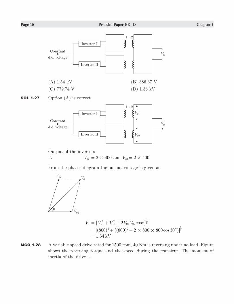
MCQ 1.27 The following figure shows a circuit for harmonic reduction of an inverter system.
Each inverter has output voltage of 400 V and each transformer has primary to
secondary turns ratio of 1 : 2 . If the firing angles for the two inverter differ by 30c
, the output voltage will be
Page 10 Practice Paper EE_D Chapter 1
(A) 1.54 kV (B) 386.37 V
(C) 772.74 V (D) 1.38 kV
SOL 1.27 Option (A) is correct.
Output of the inverters
V01 2 400#= and V 2 40002 #=
From the phaser diagram the output voltage is given as
V0 [ ]cosV V V V2012
012
01 02 21θ= + +
( ) (( ) )cos800 800 2 800 800 302 2 21
# # c= + +6 @ 1.54 kV=
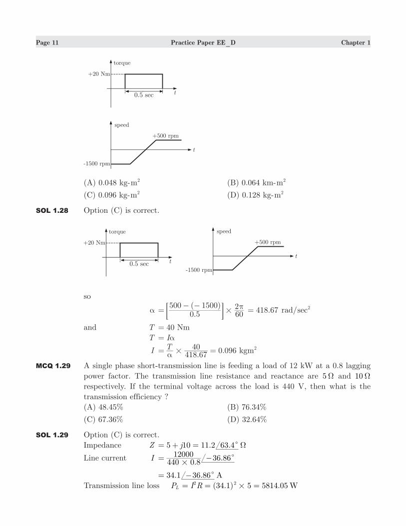
MCQ 1.28 A variable speed drive rated for 1500 rpm, 40 Nm is reversing under no load. Figure
shows the reversing torque and the speed during the transient. The moment of
inertia of the drive is
Page 11 Practice Paper EE_D Chapter 1
(A) 0.048 kg-m2 (B) 0.064 km-m2
(C) 0.096 kg-m2 (D) 0.128 kg-m2
SOL 1.28 Option (C) is correct.
so
α .
( )0 5
500 1500602
#π=
− −; E .418 67= rad/sec2
and T 40 Nm=
T Iα=
I .
0.096T418 67
40 kgm2#α
= =
MCQ 1.29 A single phase short-transmission line is feeding a load of 12 kW at a 0.8 lagging
power factor. The transmission line resistance and reactance are 5Ω and 10Ω
respectively. If the terminal voltage across the load is 440 V, then what is the
transmission efficiency ?
(A) 48.45% (B) 76.34%
(C) 67.36% (D) 32.64%
SOL 1.29 Option (C) is correct.
Impedance Z . .j5 10 11 2 63 4cΩ= + =
Line current I .
.440 0 8
12000 36 86#
c= −
34.1 . A36 86c= −
Transmission line loss PL (34.1) 5 5814.05 WI R2 2#= = =
Page 12 Practice Paper EE_D Chapter 1
Power at the sending end
PS 12000 5814.05 17814.05 W= + =
Transmission efficiency
η PP 100S
R#=
.
. %17814 0512000 100 67 36#= =
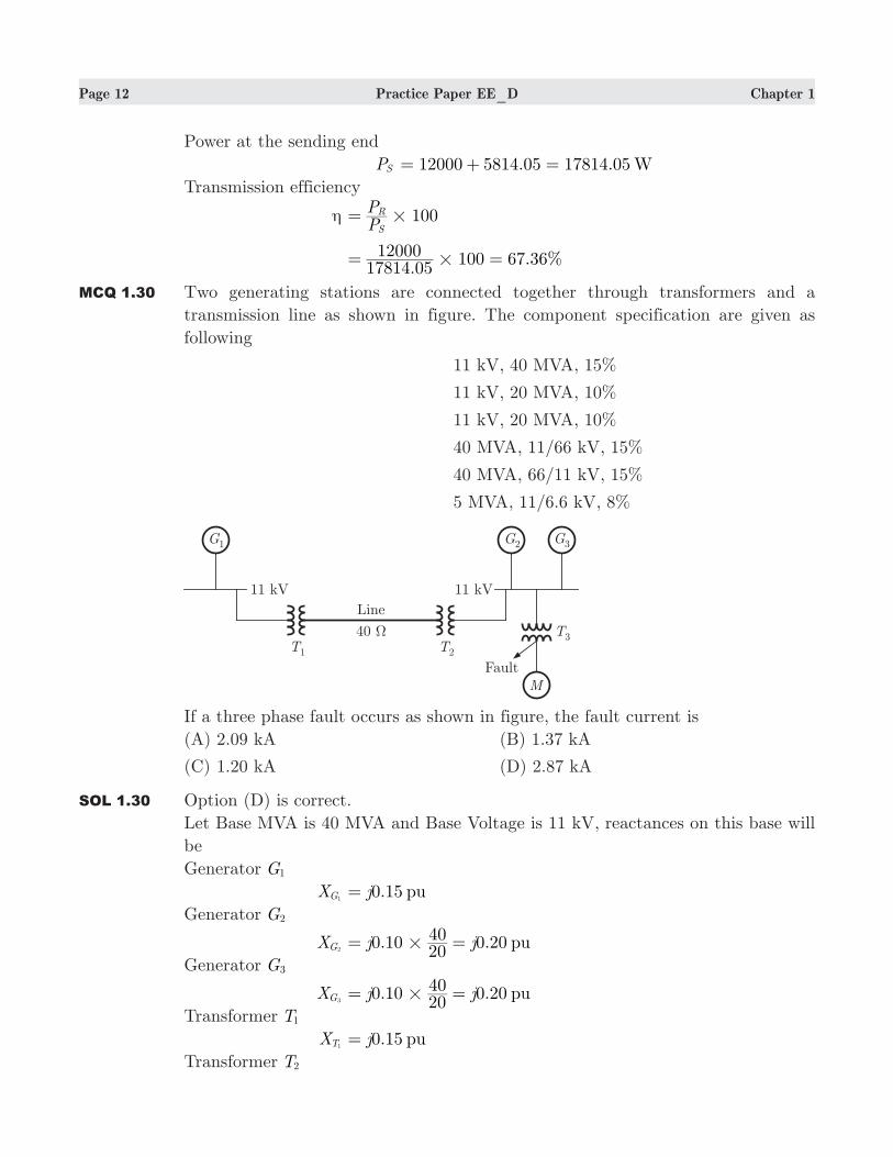
MCQ 1.30 Two generating stations are connected together through transformers and a
transmission line as shown in figure. The component specification are given as
following
11 kV, 40 MVA, 15%
11 kV, 20 MVA, 10%
11 kV, 20 MVA, 10%
40 MVA, 11/66 kV, 15%
40 MVA, 66/11 kV, 15%
5 MVA, 11/6.6 kV, 8%
If a three phase fault occurs as shown in figure, the fault current is
(A) 2.09 kA (B) 1.37 kA
(C) 1.20 kA (D) 2.87 kA
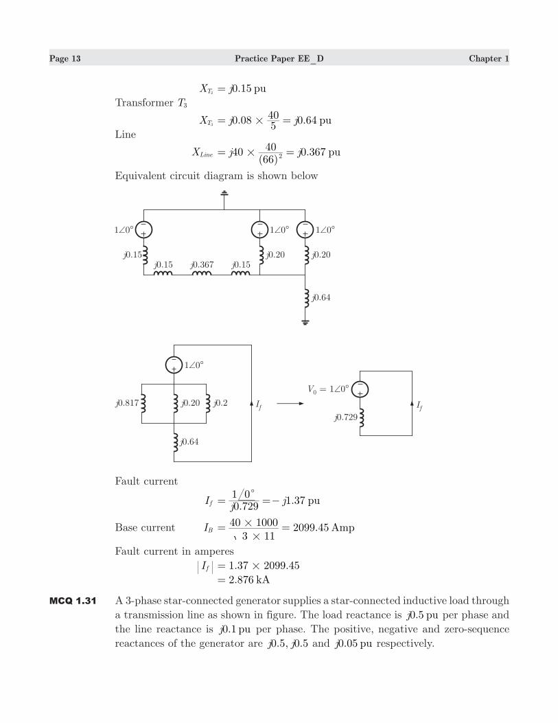
SOL 1.30 Option (D) is correct.
Let Base MVA is 40 MVA and Base Voltage is 11 kV, reactances on this base will
be
Generator G1
XG1 0.15 puj=
Generator G2
XG2 0.10 0.20 puj j
2040
#= =
Generator G3
XG3 0.10 0.20 puj j
2040
#= =
Transformer T1
XT1 0.15 puj=
Transformer T2
Page 13 Practice Paper EE_D Chapter 1
XT2 0.15 puj=
Transformer T3
XT3 0.08 0.64 puj j
540
#= =
Line
XLine 40( )
0.367 puj j6640
2#= =
Equivalent circuit diagram is shown below
Fault current
I f .1.37 pu
jj
0 7291 0c
= =−
Base current IB 2099.45 Amp3 11
40 1000
#
#= =
Fault current in amperes
I f . .1 37 2099 45#=
2.876 kA=
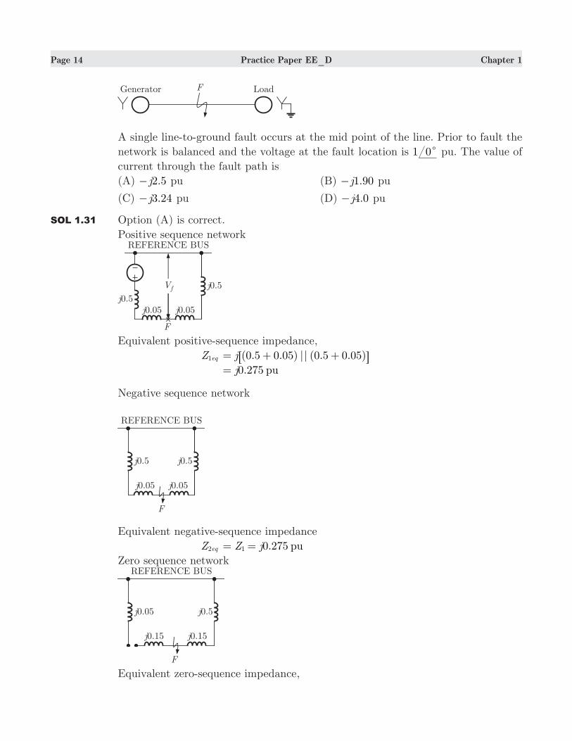
MCQ 1.31 A 3-phase star-connected generator supplies a star-connected inductive load through
a transmission line as shown in figure. The load reactance is 0.5 puj per phase and
the line reactance is 0.1 puj per phase. The positive, negative and zero-sequence
reactances of the generator are . , .j j0 5 0 5 and 0.05 puj respectively.
Page 14 Practice Paper EE_D Chapter 1
A single line-to-ground fault occurs at the mid point of the line. Prior to fault the
network is balanced and the voltage at the fault location is 1 0c pu. The value of
current through the fault path is
(A) .j2 5− pu (B) .j1 90− pu
(C) .j3 24− pu (D) .j4 0− pu
SOL 1.31 Option (A) is correct.
Positive sequence network
Equivalent positive-sequence impedance,
Z eq1 (0.5 0.05) || (0.5 0.05)j= + +6 @ 0.275 puj=
Negative sequence network
Equivalent negative-sequence impedance
Z eq2 0.275 puZ j1= =
Zero sequence network
Equivalent zero-sequence impedance,
Page 15 Practice Paper EE_D Chapter 1
Z eq0 . . .j j j3 0 05 0 5 0 65#= + =
Fault current I f Z Z ZV3
eq eq eq
f
1 2 0=
+ +
( . . . )
( )j
j
0 275 0 275 0 653 1 0#
=+ +
+
2.5 puj=−
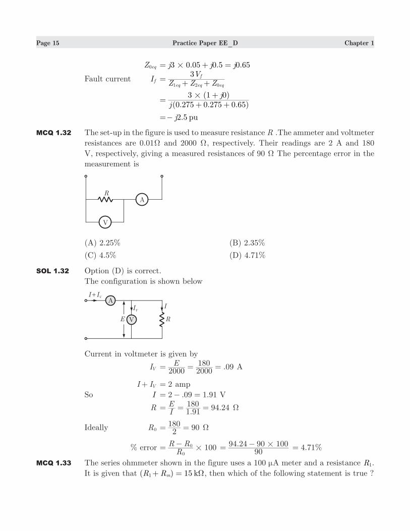
MCQ 1.32 The set-up in the figure is used to measure resistance R .The ammeter and voltmeter
resistances are 0.01Ω and 2000 Ω, respectively. Their readings are 2 A and 180
V, respectively, giving a measured resistances of 90 Ω The percentage error in the
measurement is
(A) 2.25% (B) 2.35%
(C) 4.5% (D) 4.71%
SOL 1.32 Option (D) is correct.
The configuration is shown below
Current in voltmeter is given by
IV .E2000 2000
180 09= = = A
I IV+ 2= amp
So I . .2 09 1 91= − = V
R .
.IE
1 91180 94 24= = = Ω
Ideally R0 2180 90= = Ω
% error 100RR R
0
0#=
− .90
94 24 90 100#= − .4 71= %
MCQ 1.33 The series ohmmeter shown in the figure uses a 100 µA meter and a resistance R1.
It is given that ( ) 15 kR Rm1 Ω+ = , then which of the following statement is true ?

Page 16 Practice Paper EE_D Chapter 1
(A) At 25% of full-scale deflection, the measured value of resistance Rx is 10 kΩ
(B) At 50% of full-scale deflection, the measured value of resistance Rx is 15 kΩ
(C) At 75% of full-scale deflection, the measured value of resistance Rx is 45 kΩ
(D) none of above
SOL 1.33 Option (B) is correct.
The meter current indicated by the instrument in the figure
Im R R R
Ex m
b
1=
+ +
To obtain full-scale deflection current put R 0x = in above equation
I fsd .
kV
0 151 5
Ω=+
100 Aµ=
At 50% of full scale deflection
Im 100
2A
50 Aµ
µ= =
R R Rx m1+ + IEm
b=
Rx ( )IE
R Rm
bm1= − +
501.5 15
AV kµ
Ω= −
15 kΩ=
At 25% of full-scale deflection
Im 100
25A
A4µ
µ= =
Rx 251.5 15
AV kµ
Ω= − 45 kΩ=
At 75% of full scale-deflection
Im 0.75 100 75A Aµ µ#= =
Rx 751.5 15
AV kµ
Ω= − 5 k1 Ω=
MCQ 1.34 A 4 kHz sinusoidal signal is being observed on the screen of a CRO. For a sweep
frequency of 8 kHz and 2 kHz, the number of cycles of the input signal appeared
on the screen will be respectively
(A) 1, 4 (B) 0.5, 1
(C) 4, 1 (D) 0.5, 2
Page 17 Practice Paper EE_D Chapter 1
SOL 1.34 Option (D) is correct.
Duration of one cycle of input
T 0.25 sec41 m= =
When the sweep frequency is 8 kHz, duration of one cycle of sweep
Ts 81 0.125 msec= =
no of cycles appeared on the screen .. .0 250 125 0 5= =
When the sweep frequency is 8 kHz, duration of one cycle of sweep
Ts2 21 0.50 msec= =
no of cycles appeared on the screen ..
0 250 50 2= =
MCQ 1.35 A 50 Hz, bar primary CT has a secondary with 300 turns. The resistance and
reactance of secondary circuits are .1 3Ω and .0 8Ω respectively and it supplies a
current of 5 A. The core requires an equivalent of mmf of 90 AT for magnetization
and 45 AT for core losses. The actual ratio will be
(A) 317.1 (B) 307.6
(C) 320 (D) 309.4
SOL 1.35 Option (A) is correct.
Secondary circuit phase angle
δ .. .tan
1 30 8 31 61
c= =− b lTurn ratio Kt N
N1
300 300p
s= = =
Magnetizing current
Im sinMagneti gN
mmf
p= N 1p` =
90 A190= =
Loss component
Iw equivalent to iron loss
Nmmf
p= 45 A
145= =
Actual ratio
Kact sin cos
KI
I It
s
m wδ δ= +
+
Put, 31.6 0.8517 31.6 0.524cos cos sin sinandc cδ δ= = = =
Kact 300 . .5
90 0 524 45 0 8517# #= + + 317.1=
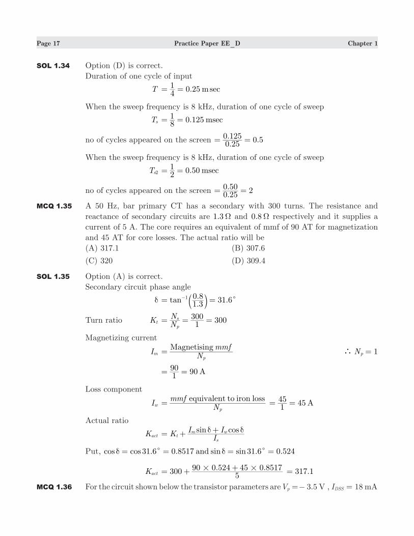
MCQ 1.36 For the circuit shown below the transistor parameters are 3.5 VVp =− , 18 mAIDSS =
Page 18 Practice Paper EE_D Chapter 1
, and 0λ = . The value of VDS is
(A) 7.43 V (B) 8.6 V
(C) 1.17− V (D) 1.17 V
SOL 1.36 Option (A) is correct.
Assume the transistor is biased in the saturation region
ID IVV1DSSP
GS2
= −b l 8m 18
.1.17m V
V13 5GS
GS
2
&= −−
=−b l V
VD 15 m8= − ^ h 0.8 8.6k V=^ h VDS 8.6 1.17 7.43= − = V
V VGS P− 1.17 ( 3.5) 2.33=− − − = V
V V V>DS GS p− , Assumption is correct.
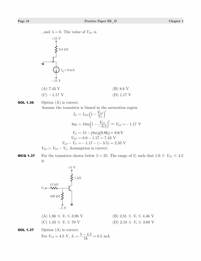
MCQ 1.37 For the transistor shown below 25β = . The range of V1 such that 1.0 4.5VCE# #
is
(A) 1.86 3.96V1# # V (B) 2.81 4.46V1# # V
(C) 1.43 79V1# # V (D) 2.18 3.69V1# # V
SOL 1.37 Option (A) is correct.
For 4.5VCE = V, . 0.5k
I1
5 4 5C =
− = mA
Page 19 Practice Paper EE_D Chapter 1
IB . 0.02
250 5= = mA
R1 15 kΩ= , 100 kR2 Ω=
IR2 . ( )
0.057k100
0 7 5=
− −= mA
IR1 I IR B1= + 0.057 0.02 0.077= + = mA
V1 I R VR BE1 1= + (0.077)15 0.7 1.855= + = V
For 1.0VCE = V
IC 4k1
5 1= − = mA,
IB 0.16254= = mA
IR2 0.057= mA
IR1 0.057 0.16 0.217= + = mA
V1 (0.217)(15) 0.7 3.96= + = V
So 1.86 3.96V1# # V
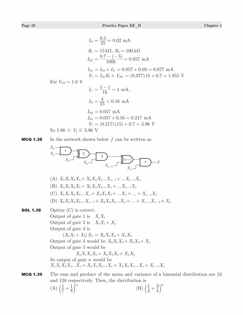
MCQ 1.38 In the network shown below f can be written as
(A) ... ...X X X X X X X X X Xn n n0 1 3 5 2 4 5 1 1+ +− −
(B) ... ...X X X X X X X X X Xn n n0 1 3 5 2 3 4 1+ + −
(C) ... ... ...X X X X X X X X X X Xn n n n0 1 3 5 2 3 5 1+ + + + −
(D) ... ... ...X X X X X X X X X X X Xn n n n n0 1 3 5 1 2 3 5 1 2+ + + +− − −
SOL 1.38 Option (C) is correct.
Output of gate 1 is X Xo 1
Output of gate 2 is X X X0 1 2+
Output of gate 3 is
( )X X X X0 1 2 3+ X X X X X0 1 3 2 3= +
Output of gate 4 would be X X X X X X0 1 3 2 3 4+ +
Output of gate 5 would be
X X X X X X X X X0 1 3 5 2 3 5 4 5+ +
So output of gate n would be... ... ...X X X X X X X X X X X X X X Xo n n n n n1 3 5 2 3 5 4 5 7 1+ + + −
MCQ 1.39 The sum and product of the mean and variance of a binomial distribution are 24
and 128 respectively. Then, the distribution is
(A) 71
81 12
+b l (B) 41
43 16
+b l
Page 20 Practice Paper EE_D Chapter 1
(C) 61
65 24
+b l (D) 21
21 32
+b lSOL 1.39 Option (D) is correct.
24m 2σ+ = and 128m 2σ =
On solving we get : 16m = or 8
16 8m 2& σ= = 8 56m 2
& σ= =
Case I : 16np = and 8npq =
& p21= and q
21= and 32n =
Case II : 8np = and 56npq =
& 7q = , which is not possible.
The distribution is ( )q p21
21n
32
+ = +b lMCQ 1.40 For xydx
dy= given that 1y = at 0x = . Using Euler method taking the step size 0.1,
the y at 0.4x = is
(A) 1.0611 (B) 2.4680
(C) 1.6321 (D) 2.4189
SOL 1.40 Option (A) is correct.
:x 0 0.1 0.2 0.3 0.4
Euler’s method gives
yn 1+ ( , )y h x yn n n= + ...(i)
n 0= in (1) gives
y1 ( , )y hf x y0 0 0= +
Here x 00 = , y0 1= , .h 0 1=
y1 1 0.1 (0,1) 1 0 1f= + = + =
0n = in (1) gives ( , )y y hf x y2 1 1 1= +
1 0.1 (0.1,1) 1 0.1(0.1) 1 0.01f= + = + = +
Thus 1.01y y( . )2 0 2= =
2n = in (1) gives
y3 ( , ) 1.01 0.1 (0.2,1.01)y hf x y f2 2 2= + = +
y3 1.01 0.0202 1.0302y( . )0 3= = + =
3n = in (1) gives
y3 ( , ) 1.01 0.1 (0.2,1.01)y hf x y f2 2 2= + = +
y3 1.01 0.0202 1.0302y( . )0 3= = + =
3n = in (1) gives
y4 ( , ) 1.0302 0.1 (0.3,1.0302)y hf x y f3 3 3= + = +
1.0302 0.03090= +
y4 1.0611y( . )0 4= =
Hence y( . )0 4 1.0611=
Page 21 Practice Paper EE_D Chapter 1
MCQ 1.41 The system of equations 4 7 14x y z− + = , 3 8 2 13x y z+ − = , 7 8 26 5x y z− + = has
(A) a unique solution
(B) no solution
(C) an infinite number of solution
(D) none of these
SOL 1.41 Option (B) is correct.
Here [ : ]A B
:
:
:
1
3
7
4
8
8
7
2
26
14
13
5
=
−
−
−
R
T
SSSS
V
X
WWWW
:
:
:
1
0
7
4
20
20
7
23
23
14
29
93
=
−
−
−
−
−
R
T
SSSS
V
X
WWWW
R R
R R
R
R32 1
3 1
2
3
&
&
−
−f p
:
:
:
1
0
7
4
20
0
7
23
0
14
29
64
=
−
− −
−
R
T
SSSS
V
X
WWWW R R R3 2 3&−^ h
( : )A Bρ 3& ( ) 2Aρ= = ,
( )Aρ ( : )A B! ρ
Thus system is inconsistent i.e. has no solution.
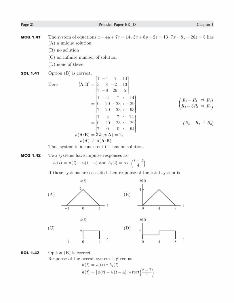
MCQ 1.42 Two systems have impulse responses as
( )h t1 ( ) ( 4)u t u t= − − and ( )h tt
42rect2 = −b l
If these systems are cascaded then response of the total system is
SOL 1.42 Option (B) is correct.
Response of the overall system is given as
( )h t ( ) ( )h t h t1 2= *
( )h t [ ( ) ( 4)]u t u tt
42rect= − − −
* b l
Page 22 Practice Paper EE_D Chapter 1
t4
2recta−b l ( ) ( 4)u t u t= − − so
( )h t [ ( ) ( 4)] ( ) ( 4)u t u t u t u t= − − − −* [ ( ) ( ) ( ) 4( 4) ( 4) ( )u t u t u t t u t u t= − − − −* * * ( 4) ( 4)]u t u t+ − −* ( ) ( )u t u ta * ( )tramp=
so, ( )h t [ ( ) ( 4) ( 4) ( 8)]t t t tramp ramp ramp ramp= − − − − + −
( )G t ramp(t) 2ramp(t 4) ramp(t 8)= − − + −
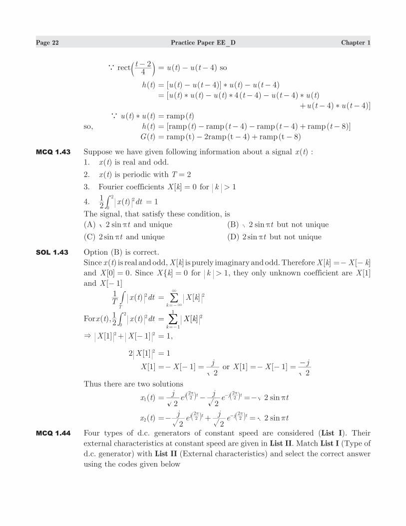
MCQ 1.43 Suppose we have given following information about a signal ( )x t :
1. ( )x t is real and odd.
2. ( )x t is periodic with 2T =
3. Fourier coefficients [ ] 0X k = for 1k >
4. ( )x t dt21 2
0
2# 1=
The signal, that satisfy these condition, is
(A) sin t2 π and unique (B) sin t2 π but not unique
(C) 2 sin tπ and unique (D) 2 sin tπ but not unique
SOL 1.43 Option (B) is correct.
Since ( )x t is real and odd, [ ]X k is purely imaginary and odd. Therefore [ ] [ ]X k X k=− −
and [0] 0X = . Since ] 0X k = for 1k > , they only unknown coefficient are [1]X
and [ 1]X −
( )T
x t dt1
T
2# [ ]X kk
2=3
3
=−
/
For ( ), ( )x t x t dt21 2
0
2# [ ]X kk
2
1
1
==−
/& [ ] [ ]X X1 12 2+ − 1= ,
2 [ ]X 1 2 1=
[1]X [ 1]Xj
2=− − = or [1] [ 1]X X
j
2=− − =
−
Thus there are two solutions
( )x t1 sinje
je t
2 22
2 2j t j t
2 2 π= − =−π π
−b bl l
( )x t2 sinje
je t
2 22j t j t
22
22
π=− + =π π
−b bl l
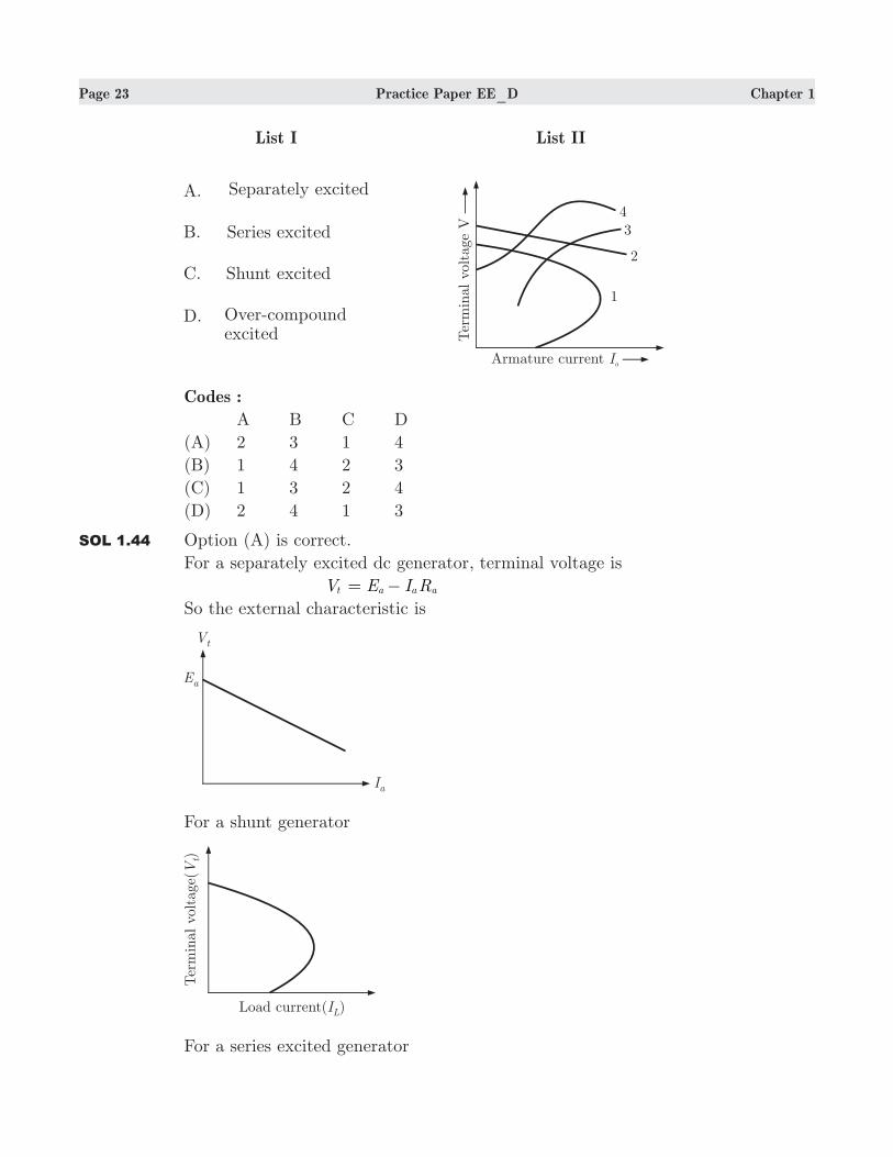
MCQ 1.44 Four types of d.c. generators of constant speed are considered (List I). Their
external characteristics at constant speed are given in List II. Match List I (Type of
d.c. generator) with List II (External characteristics) and select the correct answer
using the codes given below
Page 23 Practice Paper EE_D Chapter 1
Codes :
A B C D
(A) 2 3 1 4
(B) 1 4 2 3
(C) 1 3 2 4
(D) 2 4 1 3
SOL 1.44 Option (A) is correct.
For a separately excited dc generator, terminal voltage is
Vt E I Ra a a= −
So the external characteristic is
For a shunt generator
For a series excited generator
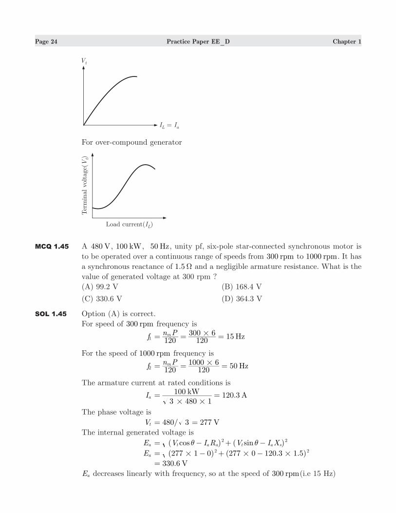
Page 24 Practice Paper EE_D Chapter 1
For over-compound generator
MCQ 1.45 A 480 V, 100 kW, 50 Hz, unity pf, six-pole star-connected synchronous motor is
to be operated over a continuous range of speeds from 00 r3 pm to 1000 rpm. It has
a synchronous reactance of 1.5Ω and a negligible armature resistance. What is the
value of generated voltage at 300 rpm ?
(A) 99.2 V (B) 168.4 V
(C) 330.6 V (D) 364.3 V
SOL 1.45 Option (A) is correct.
For speed of 00 r3 pm frequency is
f1 15 Hzn P120 120
300 6m #= = =
For the speed of 1000 rpm frequency is
f2 50 Hzn P120 120
1000 6m #= = =
The armature current at rated conditions is
Ia .kW A3 480 1100 120 3# #
= =
The phase voltage is
Vt 480/ 277 V3= =
The internal generated voltage is
Ea ( ) ( )cos sinV I R V I Xt a a t a s2 2θ θ= − + −
Ea ( ) ( . . )277 1 0 277 0 120 3 1 52 2# # #= − + −
. V330 6=
Ea decreases linearly with frequency, so at the speed of 00 r3 pm(i.e 15 Hz)
Page 25 Practice Paper EE_D Chapter 1
E ,a 300 ( . ) 9.HzHz V
5015 330 6 9 18= =
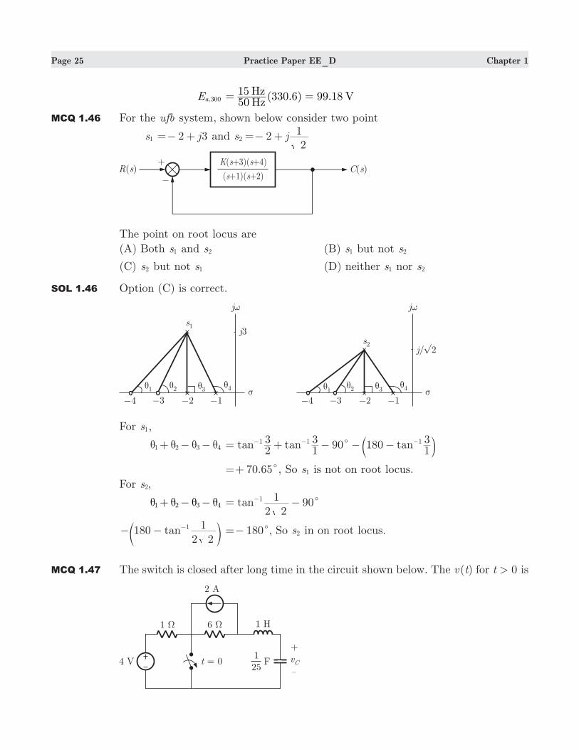
MCQ 1.46 For the ufb system, shown below consider two point
s1 2 3j=− + and 2s j2
12 =− +
The point on root locus are
(A) Both s1 and s2 (B) s1 but not s2
(C) s2 but not s1 (D) neither s1 nor s2
SOL 1.46 Option (C) is correct.
For s1,
1 2 3 4θ θ θ θ+ − − 90tan tan tan23
13 180
131 1 1
c= + − − −− − −b l 70.65 ,c=+ So s1 is not on root locus.
For ,s2
1 2 3 4θ θ θ θ+ − − 90tan2 2
11c= −−
tan1802 2
11− − −c m 180c=− , So s2 in on root locus.
MCQ 1.47 The switch is closed after long time in the circuit shown below. The ( )v t for 0t > is
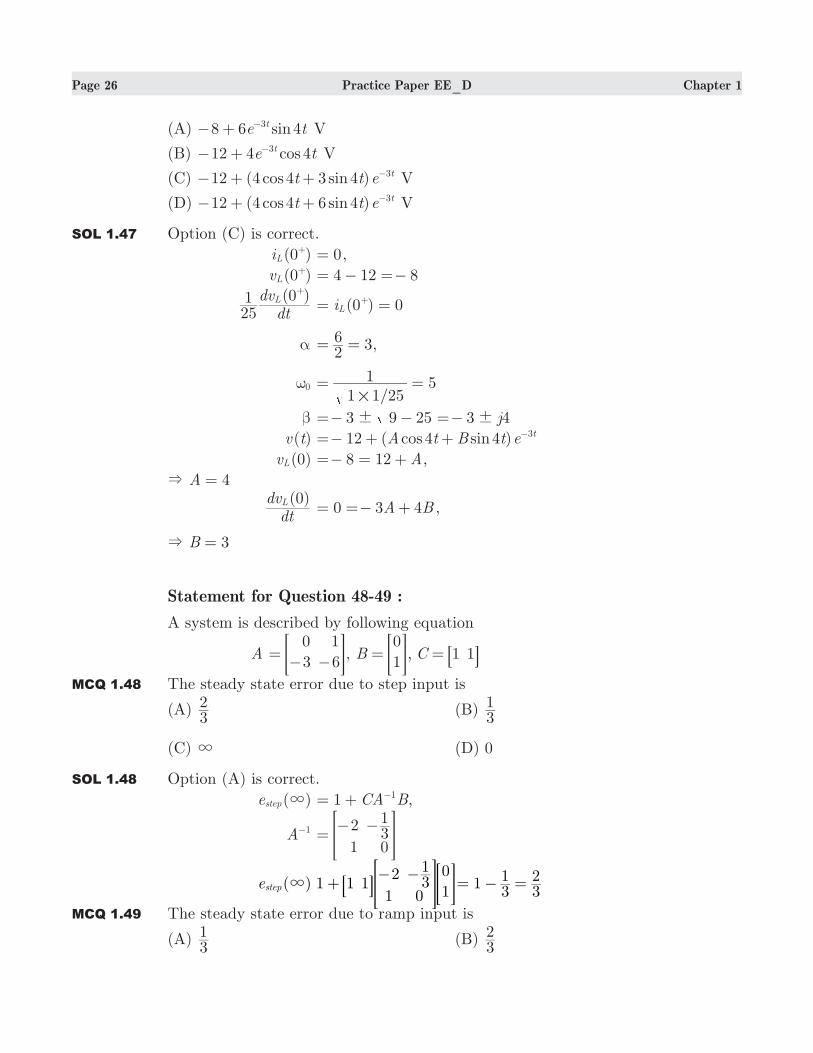
Page 26 Practice Paper EE_D Chapter 1
(A) 8 6 4sine tt3− + − V
(B) 12 4 4cose tt3− + − V
(C) 12 (4 4 3 4 )cos sint t e t3− + + − V
(D) 12 (4 4 6 4 )cos sint t e t3− + + − V
SOL 1.47 Option (C) is correct.
(0 )iL+ 0= ,
(0 )vL+ 4 12 8= − =−
( )dt
dv251 0L
+
(0 ) 0iL= =+
α 3,26= =
0ω /1 1 25
1 5#
= =
β 3 3 4j9 25! !=− − =−
( )v t 12 ( 4 4 )cos sinA t B t e t3=− + + −
(0)vL 8 12 A=− = + ,
& 4A =
( )dtdv 0L 0 3 4A B= =− + ,
& 3B =
Statement for Question 48-49 :
A system is described by following equation
A 0
3
1
6=− −> H, B 0
1= > H, C 1 1= 8 B
MCQ 1.48 The steady state error due to step input is
(A) 32 (B)
31
(C) 3 (D) 0
SOL 1.48 Option (A) is correct.
( )estep 3 1 ,CA B1= + −
A 1− 2
131
0=− −> H
( )estep 3 1 1 12
131
0
0
1+
− −8 > >B H H 131
32= − =
MCQ 1.49 The steady state error due to ramp input is
(A) 31 (B)
32
Page 27 Practice Paper EE_D Chapter 1
(C) 3 (D) 0
SOL 1.49 Option (C) is correct.
( )eramp 3 ( ) ( )lim CA B t C A B1t
1 1 2= + +"3
− −6 @ 1 CA B1+ −
32= ,
( )eramp 3 ( )lim t C A B32
t
1 23= + =
"3
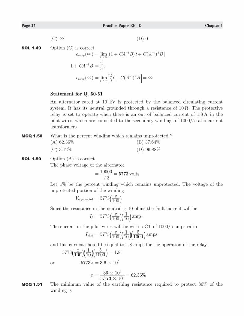
−: DStatement for Q. 50-51
An alternator rated at 10 kV is protected by the balanced circulating current
system. It has its neutral grounded through a resistance of 10Ω. The protective
relay is set to operate when there is an out of balanced current of 1.8 A in the
pilot wires, which are connected to the secondary windings of 1000/5 ratio current
transformers.
MCQ 1.50 What is the percent winding which remains unprotected ?
(A) 62.36% (B) 37.64%
(C) 3.12% (D) 96.88%
SOL 1.50 Option (A) is correct.
The phase voltage of the alternator
5773 volts3
10000= =
Let %x be the percent winding which remains unprotected. The voltage of the
unprotected portion of the winding
Vunprotected 5773100x= a k
Since the resistance in the neutral is 10 ohms the fault current will be
I f 5773100 10
1 ampx= a bk l .
The current in the pilot wires will be with a CT of 1000/5 amps ratio
Ipilot 5773100 10
11000
5 ampsx= a b bk l land this current should be equal to 1.8 amps for the operation of the relay.
5773100 10
11000
5xa b bk l l .1 8=
or x5773 .3 6 105#=
x .
. %5 773 1036 10 62 363
4
#
#= =
MCQ 1.51 The minimum value of the earthing resistance required to protect 80% of the
winding is
Page 28 Practice Paper EE_D Chapter 1
(A) .12 82Ω (B) .3 20Ω
(C) .16 04Ω (D) .2 07 Ω
SOL 1.51 Option (B) is correct.
To protect 80% of the winding, the unprotected portion is 20%. The voltage of the
unprotected portion
Vunprotected 5773 0.2 1154.6 volts#= =
Let R be the minimum value of the earthing resistance; the fault current will be
I f . ampR
1154 6=
The fault current through the pilot wire will be
I f .
10005 amp
R1154 6= b l
This should equal the operating current of 1.8 amp
or .1000
5R
1154 6b l .1 8=
or R 1800
5 1154.6 .3 20Ω#= =
Statement for Q. 52-53 :
A 120 V, 2400 rpm dc shunt motor operates at its rated speed at full-load and
draws 14.75 A current. The armature resistance is 0.4Ω and shunt field resistance
is 160Ω. The no-load current is 2 A. An external resistance of 3.6Ω is now inserted
in series with the armature while the torque developed is unchanged.
MCQ 1.52 The no-load speed of the motor before adding the external resistance is
(A) 2297.5 rpm (B) 2300 rpm
(C) 2507 rpm (D) 2214 rpm
SOL 1.52 Option (C) is correct.
The field current I f 120/160 0.75 A= =
At no-load condition :
Armature current I ,a nL 2 0.75 1.25 A= − =
Induced Emf E ,a nL 120 1.25 0.4 119.5 V#= − =
The power developed at no load accounts for the rotational loss in the motor.
From full-load data :
Armature current I ,a fL 14.75 0.75 14 A= − =
Induced Emf E ,a fL 120 14 0.4 114.4 V#= − =
Speed N fL 2400 rpm=
Hence, the no-load speed:
NnL NEE
,
,fL
a fL
a nL#=
2400.. 2507 rpm
114 4119 5
.#=
Page 29 Practice Paper EE_D Chapter 1
MCQ 1.53 The full-load efficiency of the motor after adding the external resistance would be
(A) 42.2% (B) 46.1%
(C) 60.95% (D) 55.1%
SOL 1.53 Option (B) is correct.
With external resistance in the armature circuit and no change in the torque
developed
Armature current Ia 14 AI ,a fL= =
Induced Emf Ea 120 14 (0.4 3.6) 64 V#= − + =
Power developed Pd 64 14 896 W#= =
Speed in this condition
Nm NEE
fLa fL
an#=
.
2400 1343 rpm114 464
.#=
Developed Power at no-load
P ,d nL 119.5 1.25 149.38 W#= =
Rotational loss after adding the external resistance
Pr NN
P ,nL
md nL#=
149.38 80 W25071343
#= =
The power output and the efficiency are
Pout 896 80 816 W= − =
Input power Pin 14.75 120 1770 W#= =
η PP 100in
out#=
. %1770816 100 46 1#= =
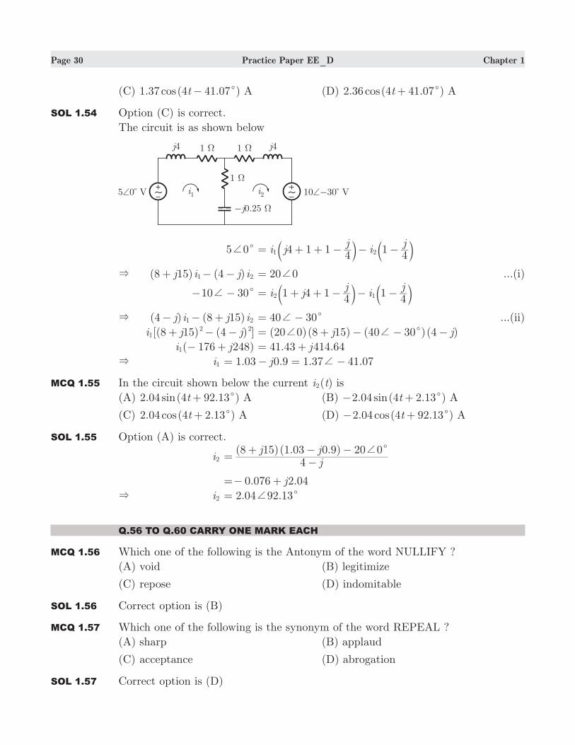
Statement for Q. 54-55:
The circuit is as shown below
MCQ 1.54 In the circuit below the current ( )i t1 is
(A) 2.36 (4 41.07 )cos t c− A (B) 2.36 (4 41.07 )cos t c+ A
Page 30 Practice Paper EE_D Chapter 1
(C) 1.37 (4 41.07 )cos t c− A (D) 2.36 (4 41.07 )cos t c+ A
SOL 1.54 Option (C) is correct.
The circuit is as shown below
5 0c+ i jj
ij
4 1 14
141 2= + + − − −b bl l
& (8 15) (4 )j i j i1 2+ − − 20 0+= ...(i)
10 30c+− − i jj
ij
1 4 14
142 1= + + − − −b bl l
& (4 ) (8 15)j i j i1 2− − + 40 30c+= − ...(ii)
[(8 15) (4 ) ]i j j12 2+ − − (20 0)(8 15) (40 30 )(4 )j jc+ += + − − −
( 176 248)i j1 − + 41.43 414.64j= +
& i1 1.03 0.9 1.37 41.07j += − = −
MCQ 1.55 In the circuit shown below the current ( )i t2 is
(A) 2.04 (4 92.13 )sin t c+ A (B) 2.04 (4 2.13 )sin t c− + A
(C) 2.04 (4 2.13 )cos t c+ A (D) 2.04 (4 92.13 )cos t c− + A
SOL 1.55 Option (A) is correct.
i2 ( )( . . )
jj j
48 15 1 03 0 9 20 0c+
=−
+ − −
0.076 2.04j=− +
& i2 2.04 92.13c+=
Q.56 TO Q.60 CARRY ONE MARK EACH
MCQ 1.56 Which one of the following is the Antonym of the word NULLIFY ?
(A) void (B) legitimize
(C) repose (D) indomitable
SOL 1.56 Correct option is (B)
MCQ 1.57 Which one of the following is the synonym of the word REPEAL ?
(A) sharp (B) applaud
(C) acceptance (D) abrogation
SOL 1.57 Correct option is (D)

Page 31 Practice Paper EE_D Chapter 1
MCQ 1.58 One of the four words given in the four options does not fit the set of words. The
odd word from the group, is
(A) Cardigan (B) Pullover
(C) Tuxedo (D) Sweater
SOL 1.58 Correct option is (C)
MCQ 1.59 A pair of CAPITALIZED words shown below has four pairs of words. The pair
of words which best expresses the relationship similar to that expressed in the
capitalized pair, is
UNITY : DIVERSITY
(A) Single : Multiple (B) One : Many
(C) Homogeneous : Heterogeneous (D) Singular : Plural
SOL 1.59 Correct option is (C)
MCQ 1.60 In the following sentence, a part of the sentence is left unfinished. Four different
ways of completing the sentence are indicated. The best alternative among the
four, is
The interest generated by the soccer World Cup is....................compared to the
way cricket.................the nation.
(A) milder, fascinates (B) lukewarm, electrifies
(C) tepid, inspires (D) unusual, grips
SOL 1.60 Correct option is (B)
Q.61 TO Q.65 CARRY TWO MARK EACH
MCQ 1.61 What is the smallest integer k for which 64 4>k 14 ?
(A) 3 (B) 5
(C) 6 (D) 7
SOL 1.61 Correct option is (B).
If we don’t want to do a lot of calculations, we’re going to have to manipulate the
exponents. The first step is to put the 64 and the 4 in the same terms, so let’s
make the 64 43= instead. Now the question is looking for the smallest integer k
for which 4 4>k3 14, which is the same as finding the smallest integer k for which
k3 14> . The best answer is 5.
MCQ 1.62 The angles of a polygon are in arithmetic progression. If the smallest angle is 120c
and the common difference is 10c, then how many sides does the polygon have ?
(A) 5 (B) 6
(C) 8 (D) Either (B) or (C)
Page 32 Practice Paper EE_D Chapter 1
SOL 1.62 Correct option is (B).
Smallest angle 1200= , common difference 10c= .
Maximum angle 170c= (a 180c is a straight line).
MCQ 1.63 A certain clock rings two notes at quarter past the hour, four notes at half past, and
six notes at three-quarters past. On the hour, it rings eight notes plus an additional
number of notes equal to whatever hour it is. How many notes will the clock ring
between : 002 P.M. and 5 : 00 P.M., including the rings at : 002 and :5 00 ?
(A) 72 (B) 87
(C) 96 (D) 102
SOL 1.63 Correct option is (B).
We know that the problem involves only simple arithmetic, because the rings occur
in an hourly pattern. You could set up a chart if that helps you see what’s going
on, or just take each part at a time by finding the number of rings at each interval
of time and then adding up the total rings at each interval. The total rings on the
hour 1 8= + +^ h 2 8 3 8 4 8+ + + + +^ ^ ^h h h 9 10 11 12 42= + + + = . The clock rings
twice at a quarter past and it does this 3 times, so the total rings at a quarter past
2 3 6= =] g . Likewise, the number of rings at half past 4 13 2= =] g and the number
of rings at three-quarters past 6 3 18= =] g . Adding up, 42 6 12 18 78+ + + =
MCQ 1.64 In an increasing sequence of 10 consecutive integers, the sum of the first 5 integers
is 660. What is the sum of the last 5 integers in the sequence ?
(A) 5 87 (B) 624
(C) 665 (D) 685
SOL 1.64 Correct option is (D).
Let the first 5 consecutive integers be represented by x , x 1+ , x 2+ , x 3+ and 4.x+
Then, since the sum of the integers is 606 , x x x x x1 2 3 4+ + + + + + + +^ ^ ^ ^h h h h 660= . Thus,
x5 10+ 606=
x5 506= solve for x
x 130=
The first integer in the sequence is 130, so the next integers are 131, 132
, 133 and 134. From this, the last 5 integers in the sequence, and thus their
sum, can be determined. The sum of the 6th, 7th, 8th, 9th and 10th integers is,
135 136 137 138 139 685+ + + + =
This problem can also be solved without algebra: The sum of the last 5 integers
exceeds the sum of the first 5 integers by 1 3 5 7 9 25+ + + + = because the 6th
MCQ 1.65 What will be the sum to n terms of the series ....9 99 999+ + + ?
(A) 9
10 1n+^ h (B) 10 1n910 −^ h
(C) n9
10 10 1n
−−^ h (D) n10 1n
910 − −^ h6 @

Page 33 Practice Paper EE_D Chapter 1
SOL 1.65 Correct option is (C).
The series can be written as 10 1nΣ −^ h. 10 1 n
10 110 10 1n
n
Σ Σ= − =−
−−
^ h
Answer Key
1. 2. 3. 4. 5, 6. 7. 8. 9. 10. 11. 12. 13. 14. 15.
C B B D B C A C B B D D C D C
16. 17. 18. 19. 20. 21. 22. 23. 24. 25. 26. 27. 28. 29. 30.
C D B D C C D B C C A A C C D
31. 32. 33. 34. 35. 36. 37. 38. 39. 40. 41. 42. 43. 44. 45.
A D B D A A A C D A B B B A A
46. 47. 48. 49. 50. 51. 52. 53. 54. 55. 56. 57. 58. 59. 60.
C C A C A B C B C A B D C C B
61. 62. 63. 64. 65. . .
B B B D C

Page 2 Practice paper EE_E Chapter 1
value of k is
(A) 3− (B) 3
(C) 7 (D) 11
SOL 1.4 Option (D) is correct.
( )f xl 3 12c x k2= − +
( )f cl 0= 3 12 0c c k2& − + =
& c k k6
12 144 1236
144 1231
&!= − − =
& 144 12k− 12 11k&= = .
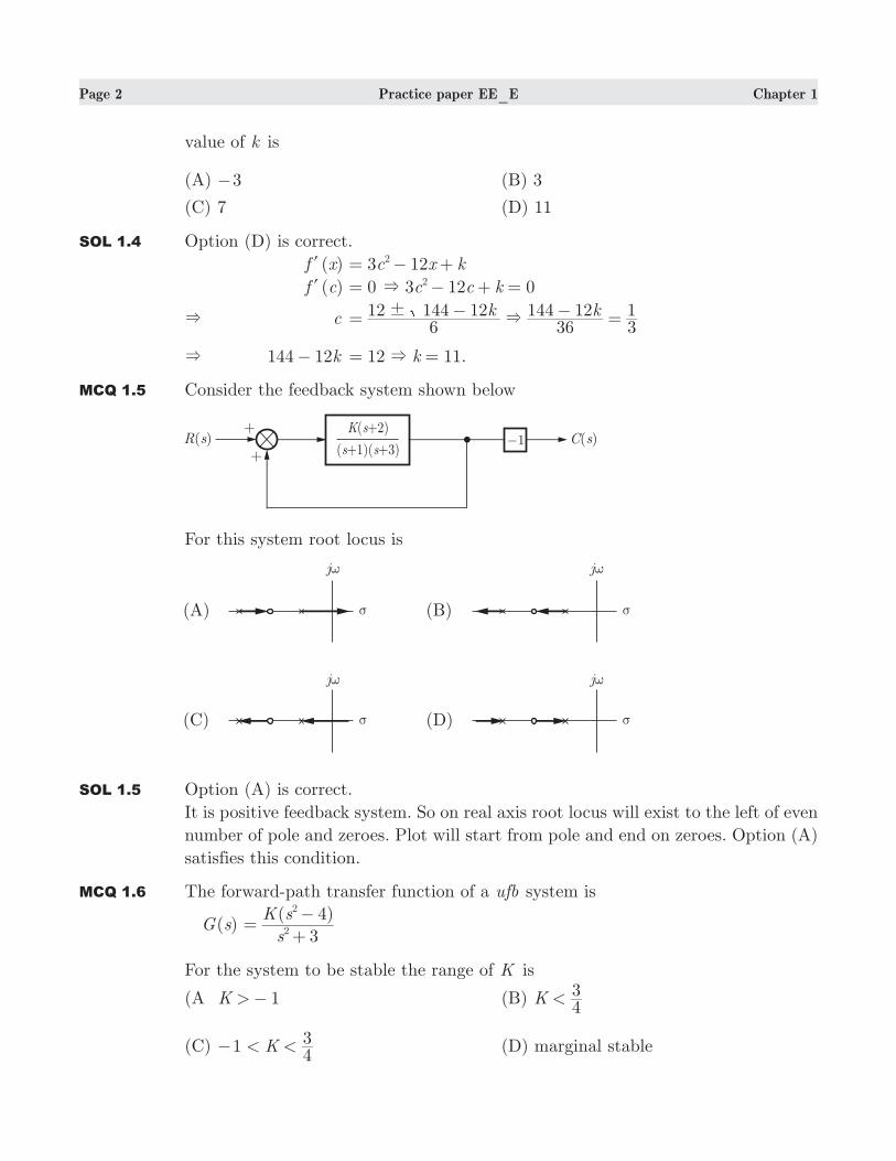
MCQ 1.5 Consider the feedback system shown below
For this system root locus is
SOL 1.5 Option (A) is correct.
It is positive feedback system. So on real axis root locus will exist to the left of even
number of pole and zeroes. Plot will start from pole and end on zeroes. Option (A)
satisfies this condition.
MCQ 1.6 The forward-path transfer function of a ufb system is
( )G s ( )
s
K s
3
42
2
=+
−
For the system to be stable the range of K is
(A 1K >− (B) K43<
(C) 1 K43< <− (D) marginal stable
Page 3 Practice paper EE_E Chapter 1
SOL 1.6 Option (D) is correct.
Closed loop transfer function
( )T s ( ) ( )
( )
K s K
K s
1 3 4
42
2
=+ + −
−
The system can be only marginally stable.
MCQ 1.7 In the signal flow graph shown below the transfer function is
(A) 3.75 (B) 3−
(C) 3 (D) 3.75−
SOL 1.7 Option (C) is correct.
P1 5 3 2 30# #= = ,
3 1 (3 3) 10#= − − = , 13 1,=
RC 3
1030= =
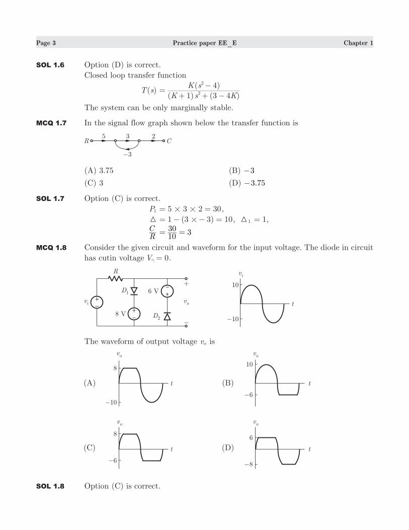
MCQ 1.8 Consider the given circuit and waveform for the input voltage. The diode in circuit
has cutin voltage 0V =γ .
The waveform of output voltage vo is
SOL 1.8 Option (C) is correct.
Page 4 Practice paper EE_E Chapter 1
During positive cycle when 8v <i V, both diode are OFF v vo i= . For 8v >i V,
8vo = V, D1 is ON. During negative cycle when 6v <i V, both diode are OFF,
v vo i= . For 6v >i V, D2 is on 6vo =− V.
MCQ 1.9 If (211) (152)x 8= , then the value of base x is
(A) 6 (B) 5
(C) 7 (D) 9
SOL 1.9 Option (C) is correct.
2 1x x2+ + 64 5 8 2#= + +
& x 7=
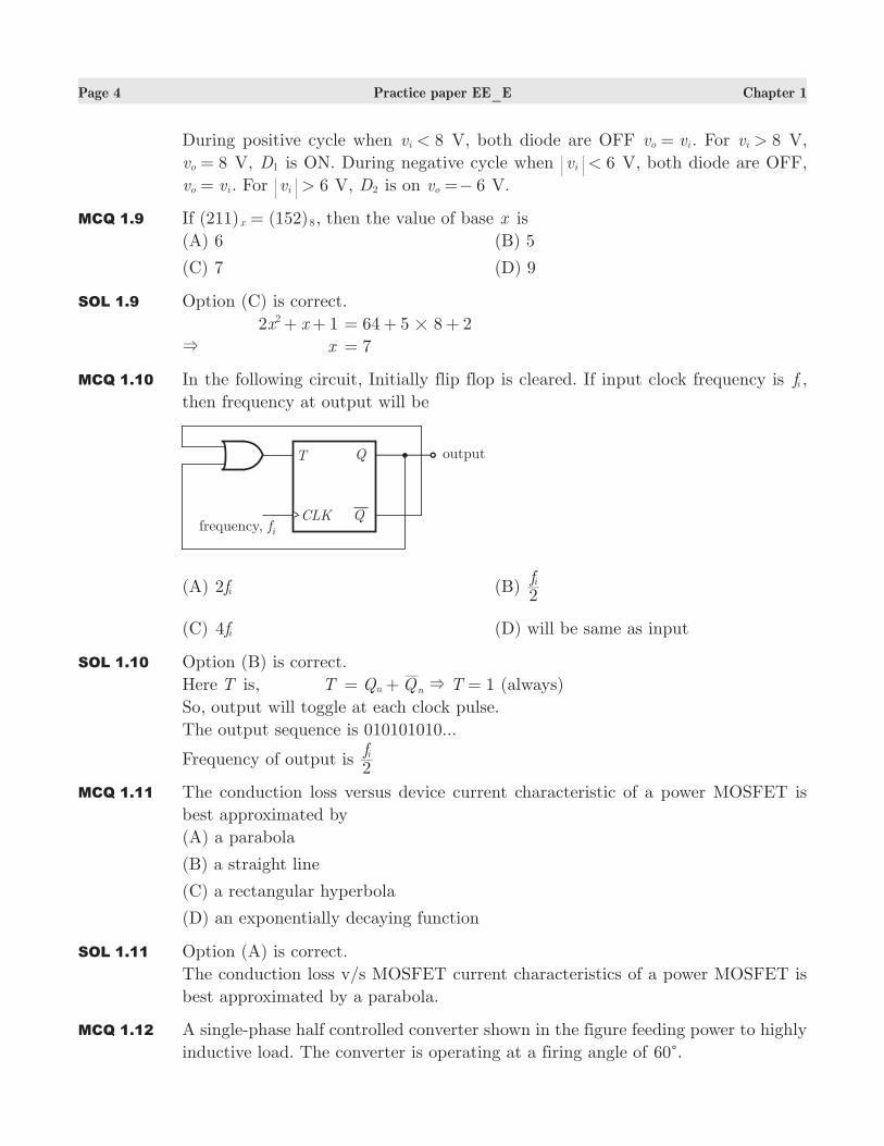
MCQ 1.10 In the following circuit, Initially flip flop is cleared. If input clock frequency is fi ,
then frequency at output will be
(A) 2fi (B) f2i
(C) 4fi (D) will be same as input
SOL 1.10 Option (B) is correct.
Here T is, T 1Q Q Tn n&= + = (always)
So, output will toggle at each clock pulse.
The output sequence is 010101010...
Frequency of output is f2i
MCQ 1.11 The conduction loss versus device current characteristic of a power MOSFET is
best approximated by
(A) a parabola
(B) a straight line
(C) a rectangular hyperbola
(D) an exponentially decaying function
SOL 1.11 Option (A) is correct.
The conduction loss v/s MOSFET current characteristics of a power MOSFET is
best approximated by a parabola.
MCQ 1.12 A single-phase half controlled converter shown in the figure feeding power to highly
inductive load. The converter is operating at a firing angle of 60c.
Page 5 Practice paper EE_E Chapter 1
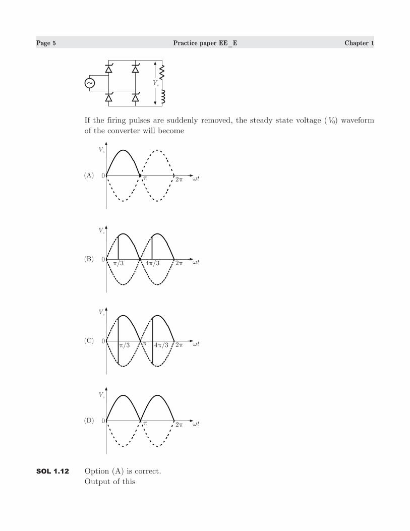
If the firing pulses are suddenly removed, the steady state voltage ( )V0 waveform
of the converter will become
SOL 1.12 Option (A) is correct.
Output of this
Page 6 Practice paper EE_E Chapter 1
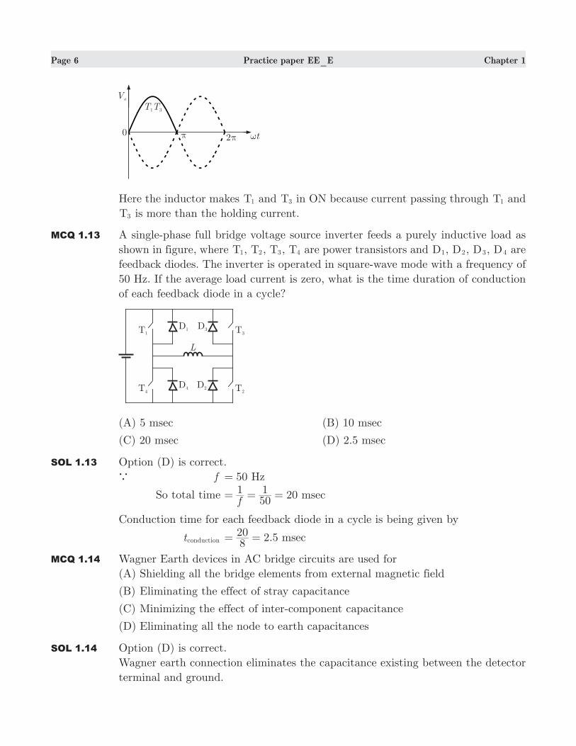
Here the inductor makes T1 and T3 in ON because current passing through T1 and
T3 is more than the holding current.
MCQ 1.13 A single-phase full bridge voltage source inverter feeds a purely inductive load as
shown in figure, where T1, T2, T3, T4 are power transistors and D1, D2, D3, D4 are
feedback diodes. The inverter is operated in square-wave mode with a frequency of
50 Hz. If the average load current is zero, what is the time duration of conduction
of each feedback diode in a cycle?
(A) 5 msec (B) 10 msec
(C) 20 msec (D) 2.5 msec
SOL 1.13 Option (D) is correct.
a f 50 Hz=
So total time 20f1
501 msec= = =
Conduction time for each feedback diode in a cycle is being given by
tconduction 2.5820 msec= =
MCQ 1.14 Wagner Earth devices in AC bridge circuits are used for
(A) Shielding all the bridge elements from external magnetic field
(B) Eliminating the effect of stray capacitance
(C) Minimizing the effect of inter-component capacitance
(D) Eliminating all the node to earth capacitances
SOL 1.14 Option (D) is correct.
Wagner earth connection eliminates the capacitance existing between the detector
terminal and ground.
Page 7 Practice paper EE_E Chapter 1
MCQ 1.15 A Lissajou pattern observed on an oscilloscope is stationary and has 5 horizontal
tangencies and 2 vertical tangencies. If the frequency of horizontal input is 1,000
Hz, then frequency of vertical input is
(A) 2500 Hz (B) 500 Hz
(C) 400 Hz (D) 2000 Hz
SOL 1.15 Option (A) is correct.
Frequency of vertical input
fy tantan
Vertical genciesHorizontal gencies
fx#=
Where fx is the frequency of horizontal input
fy 1,000 2,500 Hz25
#= =
MCQ 1.16 The errors introduced by an instrument fall in which category ?
(A) Systematic errors (B) Random errors
(C) Gross errors (D) Environmental errors
SOL 1.16 Option (A) is correct.
Systematic errors may be instrumental error, environmental error or observational
errors.
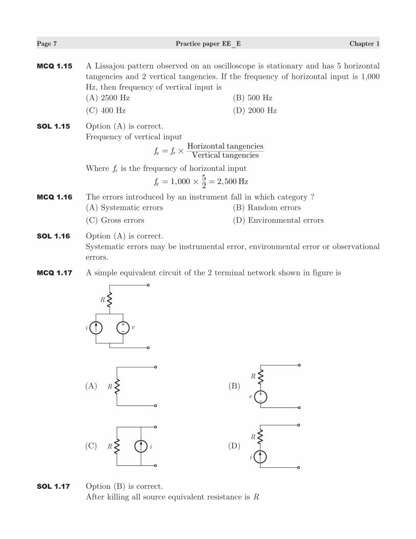
MCQ 1.17 A simple equivalent circuit of the 2 terminal network shown in figure is
SOL 1.17 Option (B) is correct.
After killing all source equivalent resistance is R
Page 8 Practice paper EE_E Chapter 1
Open circuit voltage v1=
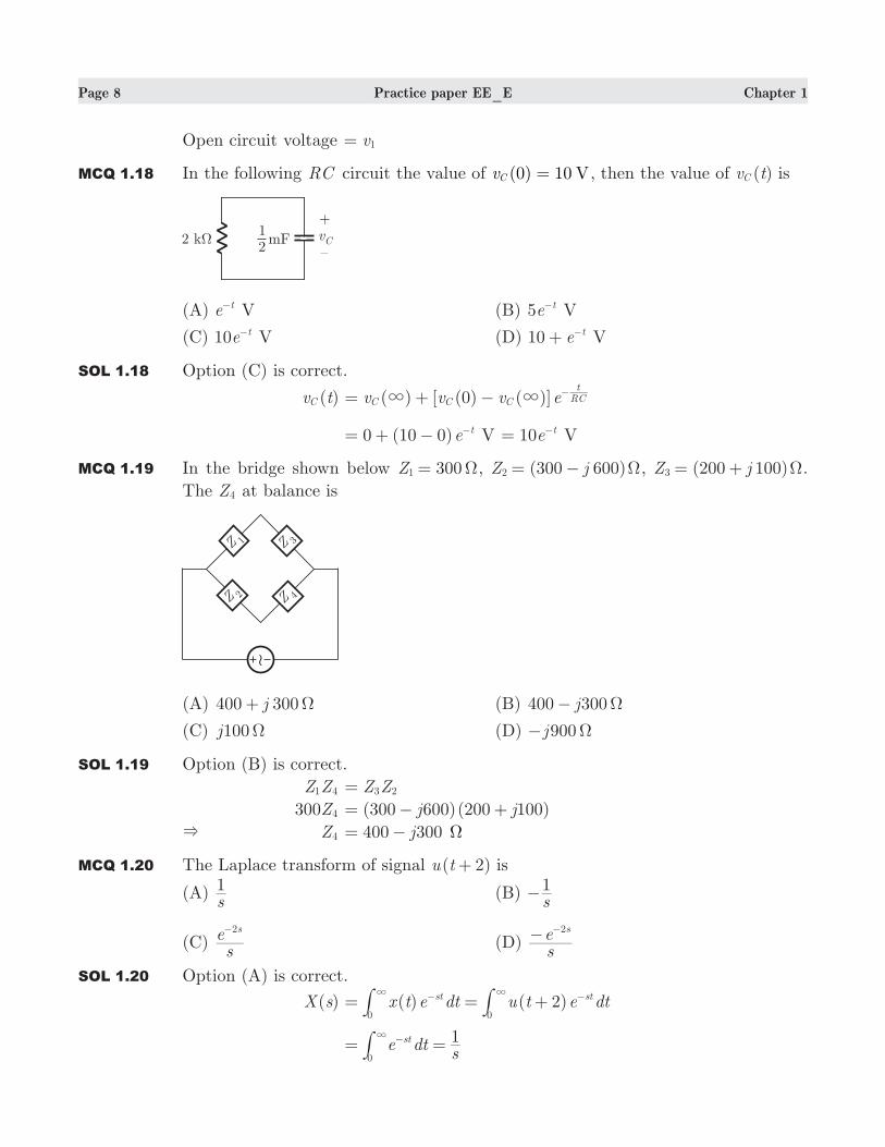
MCQ 1.18 In the following RC circuit the value of (0) 10 VvC = , then the value of ( )v tC is
(A) e t− V (B) 5e t− V
(C) 10e t− V (D) 10 e t+ − V
SOL 1.18 Option (C) is correct.
( )v tC ( ) [ (0) ( )]v v v eC C C RCt
3 3= + − −
0 (10 0)e t= + − − V 10e t= − V
MCQ 1.19 In the bridge shown below 300Z1 Ω= , (300 600)Z j2 Ω= − , (200 100)Z j3 Ω= + .
The Z4 at balance is
(A) 400 300j Ω+ (B) 400 300j Ω−
(C) 100j Ω (D) 900j Ω−
SOL 1.19 Option (B) is correct.
Z Z1 4 Z Z3 2=
300Z4 (300 600)(200 100)j j= − +
& Z4 400 300j= − Ω
MCQ 1.20 The Laplace transform of signal ( 2)u t+ is
(A) s1 (B)
s1−
(C) se s2−
(D) se s2− −
SOL 1.20 Option (A) is correct.
( )X s ( ) ( )x t e dt u t e dt2st st
00= = +
33 − −##
e dts1st
0= =
3 −#
Page 9 Practice paper EE_E Chapter 1
MCQ 1.21 A Fourier transform pairs is as following
( ) ( ) sinx t X j 2Fω
ωω= where ( )x t
,
, otherwise
t1 1
0
<= *
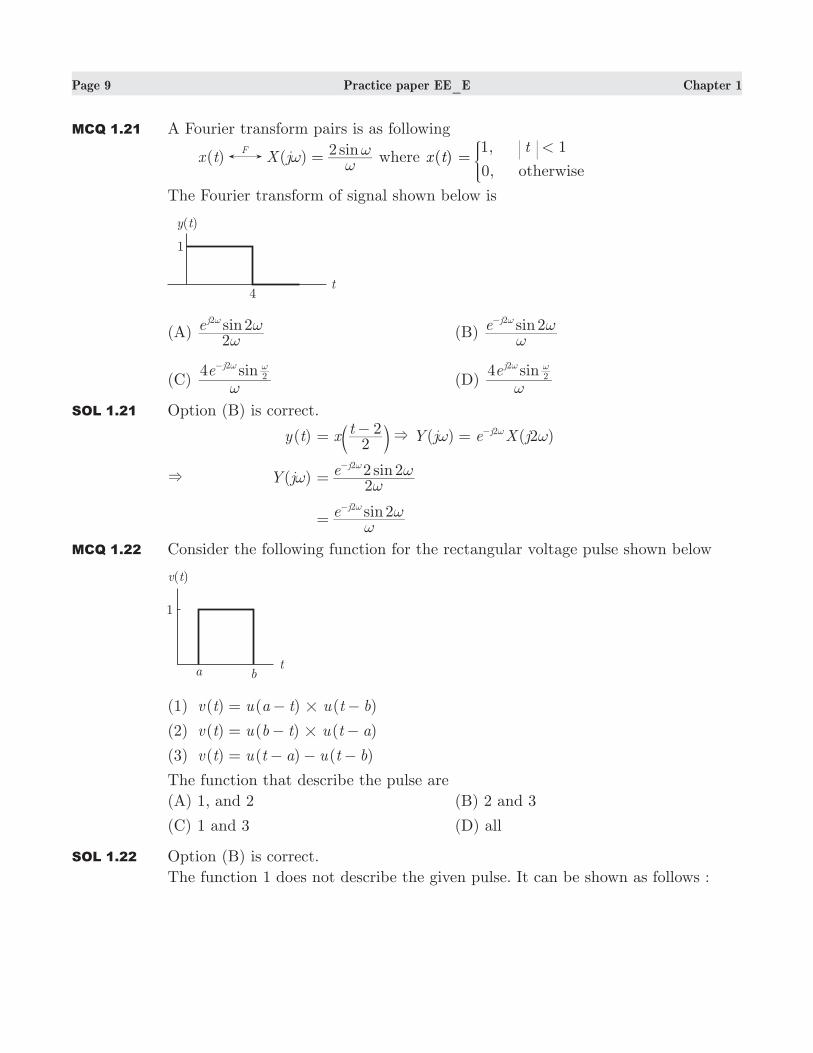
The Fourier transform of signal shown below is
(A) sine2
2j2
ωωω
(B) sine 2j2
ωωω−
(C) sine4 j2
2
ω
ω ω−
(D) sine4 j2
2
ω
ω ω
SOL 1.21 Option (B) is correct.
( )y t ( ) ( 2 )xt
Y j e X j2
2 j2& ω ω= − = ω−b l
& ( )Y jω sine22 2j2
ωω=
ω−
sine 2j2
ωω=
ω−
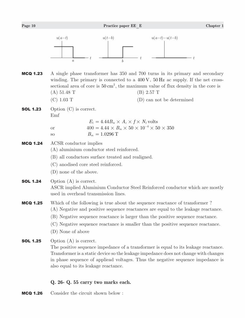
MCQ 1.22 Consider the following function for the rectangular voltage pulse shown below
(1) ( ) ( ) ( )v t u a t u t b#= − −
(2) ( ) ( ) ( )v t u b t u t a#= − −
(3) ( ) ( ) ( )v t u t a u t b= − − −
The function that describe the pulse are
(A) 1, and 2 (B) 2 and 3
(C) 1 and 3 (D) all
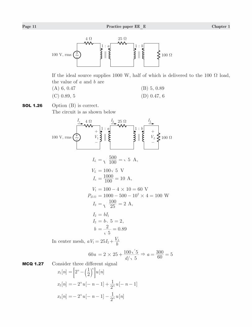
SOL 1.22 Option (B) is correct.
The function 1 does not describe the given pulse. It can be shown as follows :
Page 10 Practice paper EE_E Chapter 1
MCQ 1.23 A single phase transformer has 350 and 700 turns in its primary and secondary
winding. The primary is connected to a 400 V, 50 Hz ac supply. If the net cross-
sectional area of core is 50 cm2, the maximum value of flux density in the core is
(A) 51.48 T (B) 2.57 T
(C) 1.03 T (D) can not be determined
SOL 1.23 Option (C) is correct.
Emf
E1 4.44 voltsB A f Nm c 1# # #=
or 400 . B4 44 50 10 50 350m4
# # # # #= −
so Bm 1.0296 T=
MCQ 1.24 ACSR conductor implies
(A) aluminium conductor steel reinforced.
(B) all conductors surface treated and realigned.
(C) anodised core steel reinforced.
(D) none of the above.
SOL 1.24 Option (A) is correct.
ASCR implied Aluminium Conductor Steel Reinforced conductor which are mostly
used in overhead transmission lines.
MCQ 1.25 Which of the following is true about the sequence reactance of transformer ?
(A) Negative and positive sequence reactances are equal to the leakage reactance.
(B) Negative sequence reactance is larger than the positive sequence reactance.
(C) Negative sequence reactance is smaller than the positive sequence reactance.
(D) None of above
SOL 1.25 Option (A) is correct.
The positive sequence impedance of a transformer is equal to its leakage reactance.
Transformer is a static device so the leakage impedance does not change with changes
in phase sequence of appliead voltages. Thus the negative sequence impedance is
also equal to its leakage reactance.
Q. 26- Q. 55 carry two marks each.
MCQ 1.26 Consider the circuit shown below :
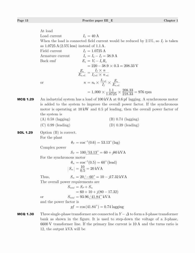
Page 11 Practice paper EE_E Chapter 1
If the ideal source supplies 1000 W, half of which is delivered to the 100 Ω load,
the value of a and b are
(A) 6, 0.47 (B) 5, 0.89
(C) 0.89, 5 (D) 0.47, 6
SOL 1.26 Option (B) is correct.
The circuit is as shown below
IL 100500 5= = A,
VL 100 5= V
Is 101001000= = A,
V1 100 4 10 60#= − = V
P25Ω 1000 500 10 4 1002#= − − = W
I2 225100= = A,
I2 bI1=
I2 2b 5= = ,
b 0.895
2= =
In center mesh, 25aV IbVL
1 2= +
60a 2 25/
5d
a5
100 560300
&#= + = =
MCQ 1.27 Consider three different signal
[ ]x n1 [ ]u n221nn
= − b l; E [ ]x n2 2 [ 1] [ 1]u n u n
21nn=− − − + − −
[ ]x n3 2 [ 1] [ ]u n u n21nn=− − − −

Page 12 Practice paper EE_E Chapter 1
Following figure shows the three different region. Choose the correct for the ROC
of signal
R1 R2 R3
(A) [ ]x n1 [ ]x n2 [ ]x n3
(B) [ ]x n2 [ ]x n3 [ ]x n1
(C) [ ]x n1 [ ]x n3 [ ]x n2
(D) [ ]x n3 [ ]x n2 [ ]x n1
SOL 1.27 Option (C) is correct.
[ ]x n1 is right-sided signal
2,z z21> >1 1 gives 2z >1
[ ]x n2 is left-sided signal
2,z z21< <2 2 gives z
21<2
[ ]x n3 is double sided signal
z21>3 and 2z <3 gives 2z
21 < <3
MCQ 1.28 A 220 V dc shunt motor takes 5 A current on no load while running at a speed
of 1000 rpm. It has an armature and a shunt field resistance of 0.3Ω and 200Ω
respectively. Now the motor is driving a load drawing 40 A current from the
supply. If the armature reaction weakens the field by 2.5% on this load, what would
be speed of the motor ?
Assume magnetic circuit to be unsaturated.
(A) 954 rpm (B) 976 rpm
(C) 1023 rpm (D) 238.5 rpm
SOL 1.28 Option (B) is correct.
At no load
Load Current InL 5 A=
Field current I ,f nL 1.1 A200220= =
Armature current I ,a nL 5 1.1 3.9 AI I ,nL f nL= − = − =
Back emf E ,a nL V I R,t a nL a= −
220 3.9 0.3 218.83 V#= − =
Page 13 Practice paper EE_E Chapter 1
At load
Load current IL 40 A=
When the load is connected field current would be reduced by 2.5%, so I f is taken
as 1.0725 (2.5% )A less instead of 1.1 A.
Field current I f 1. A0725=
Armature current Ia 38.9 AI IL f= − =
Back emf Ea V I Rt a a= −
. . 208.33 V220 38 9 0 3#= − =
EE
,a nL
a I nI n
,f nL nL
f
#
#=
or n nII
EE,
,f
f nL
a nL
a0# #=
1,000.
... 976 rpm
1 07251 1
218 33208 33
# #= =
MCQ 1.29 An industrial system has a load of 100 kVA at 0.6 pf lagging. A synchronous motor
is added to the system to improve the overall power factor. If the synchronous
motor is operating at 10 kW and 0.5 pf leading, then the overall power factor of
the system is
(A) 0.58 (lagging) (B) 0.74 (lagging)
(C) 0.99 (leading) (D) 0.39 (leading)
SOL 1.29 Option (B) is correct.
For the plant
Pθ (0.6) 53.13 ( )cos lag1c= =−
Complex power
SP 100 . 60 80 kVAj53 13c= = +
For the synchronous motor
mθ (0.5) 60 ( )cos lead1c= =−
Sm .
20 kVA0 510= =
Thus, Sm 20 10 17.32 kVAj60c= − = −
The overall power requirements are
Stotal S SP m= +
( . )j60 10 80 17 32= + + −
or Stotal 93.96 . kVA41 84c=
and the power factor is
pf (41.84 ) 0.74cos laggingc= =
MCQ 1.30 Three single-phase transformer are connected in Y ∆− to form a 3-phase transformer
bank as shown in the figure. It is used to step-down the voltage of a 3-phase,
6600 V transformer line. If the primary line current is 10 A and the turns ratio is
12, the output kVA will be
Page 14 Practice paper EE_E Chapter 1
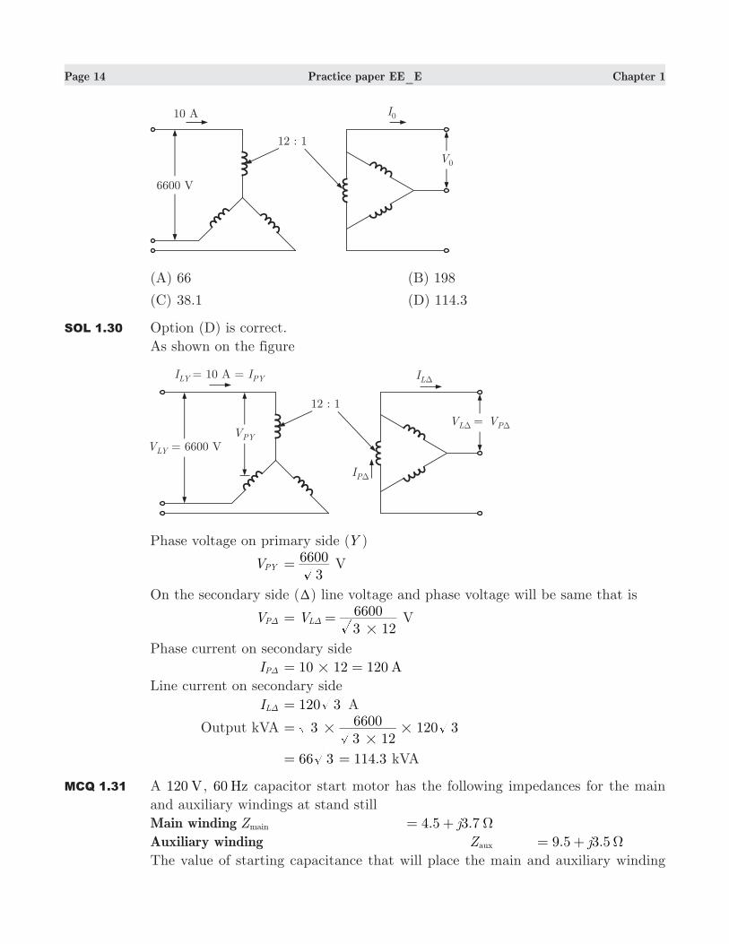
(A) 66 (B) 198
(C) 38.1 (D) 114.3
SOL 1.30 Option (D) is correct.
As shown on the figure
Phase voltage on primary side (Y )
VPY 3
6600= V
On the secondary side (T) line voltage and phase voltage will be same that is
VP∆ V3 126600
L
#= =∆ V
Phase current on secondary side
IP∆ 10 12 120 A#= =
Line current on secondary side
IL∆ 120 3= A
Output kVA 12033 126600 3#
# #=
.66 3 114 3= = kVA
MCQ 1.31 A 120 V, 60 Hz capacitor start motor has the following impedances for the main
and auxiliary windings at stand still
Main winding Zmain 4.5 3.7j Ω= +
Auxiliary winding Zaux 9.5 3.5j Ω= +
The value of starting capacitance that will place the main and auxiliary winding
Page 15 Practice paper EE_E Chapter 1
current in quadrature at starting is
(A) 177 Fµ (B) 610 Fµ
(C) 15 Fµ (D) 125 Fµ
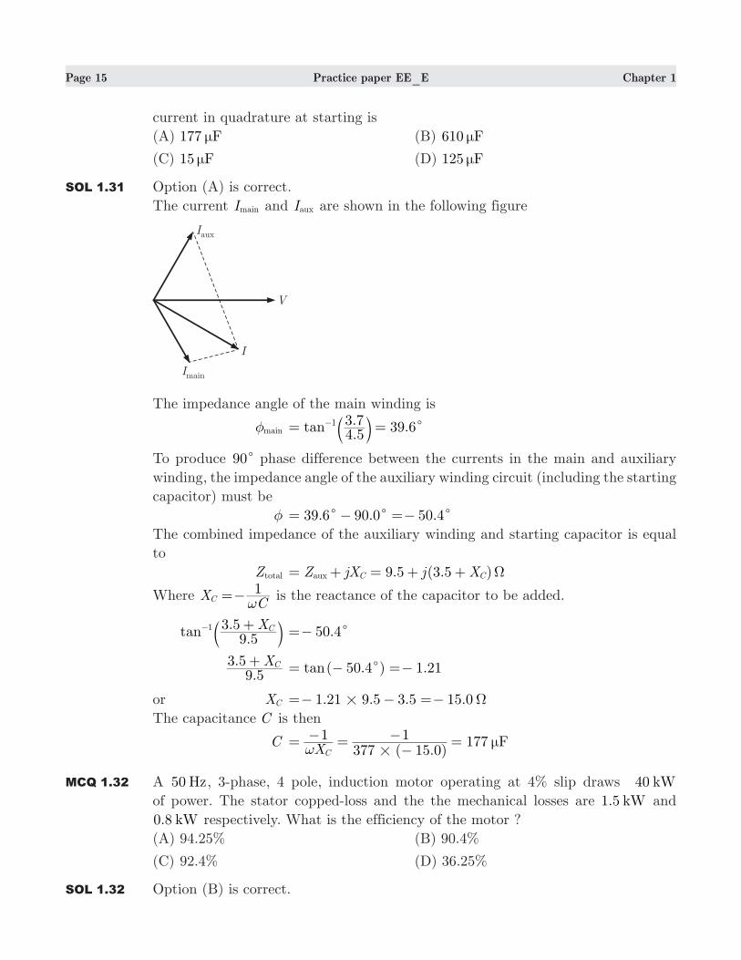
SOL 1.31 Option (A) is correct.
The current Imain and Iaux are shown in the following figure
The impedance angle of the main winding is
mainφ .. .tan
4 53 7 39 61
c= =− b lTo produce 90c phase difference between the currents in the main and auxiliary
winding, the impedance angle of the auxiliary winding circuit (including the starting
capacitor) must be
φ 39.6 90.0 .50 4c c c= − =−
The combined impedance of the auxiliary winding and starting capacitor is equal
to
Ztotal 9.5 (3.5 )Z jX j Xaux C C Ω= + = + +
Where XC1
C ω=− is the reactance of the capacitor to be added.
.
.tan X9 5
3 5 C1 +− b l .50 4c=−
.
. X9 5
3 5 C+ ( . ) .tan 50 4 1 21c= − =−
or XC 1.21 9.5 3.5 15.0Ω#=− − =−
The capacitance C is then
C ( . )
177 FX1
377 15 01
C #µ
ω= − =
−− =
MCQ 1.32 A 50 Hz, 3-phase, 4 pole, induction motor operating at 4% slip draws 40 kW
of power. The stator copped-loss and the the mechanical losses are 1. kW5 and
. kW0 8 respectively. What is the efficiency of the motor ?
(A) 94.25% (B) 90.4%
(C) 92.4% (D) 36.25%
SOL 1.32 Option (B) is correct.
Page 16 Practice paper EE_E Chapter 1
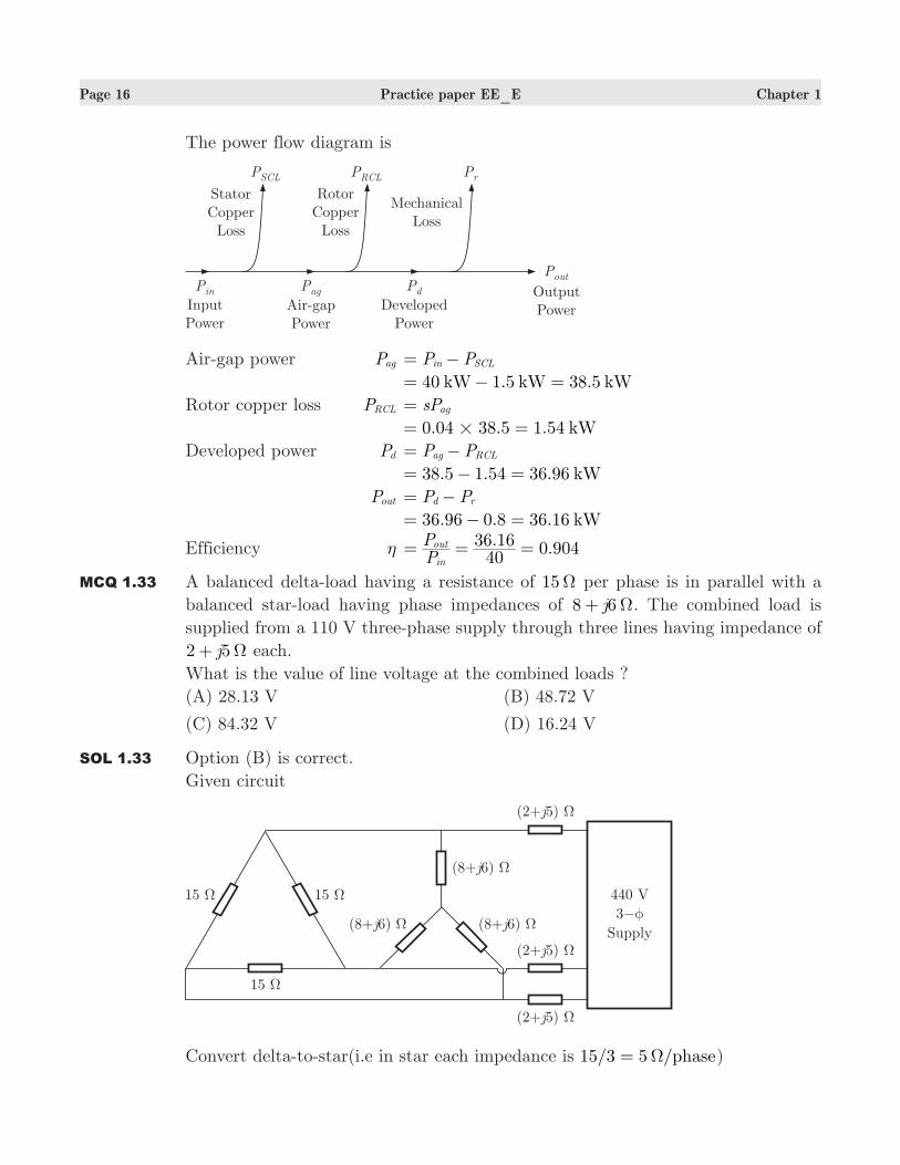
The power flow diagram is
Air-gap power Pag P Pin SCL= −
40 1.5 38.5kW kW kW= − =
Rotor copper loss PRCL sPag=
0.04 38.5 1.54 kW#= =
Developed power Pd P Pag RCL= −
38.5 1.54 36.96 kW= − =
Pout P Pd r= −
36.96 0.8 36.16 kW= − =
Efficiency η . 0.904PP
4036 16
in
out= = =
MCQ 1.33 A balanced delta-load having a resistance of 15Ω per phase is in parallel with a
balanced star-load having phase impedances of j8 6Ω+ . The combined load is
supplied from a 110 V three-phase supply through three lines having impedance of
j2 5Ω+ each.
What is the value of line voltage at the combined loads ?
(A) 28.13 V (B) 48.72 V
(C) 84.32 V (D) 16.24 V
SOL 1.33 Option (B) is correct.
Given circuit
Convert delta-to-star(i.e in star each impedance is 15/3 5 /phaseΩ= )
Page 17 Practice paper EE_E Chapter 1
Impedances in parallel per phase
( )
jj
5 8 65 8 6+ ++
jj
jj j
13 640 30
13 613 6
205700 50
#=++
−−
=+
. . . .j3 41 0 732 3 49 12 1cΩ= + =
Total impedance per phase
Z 2 5 3.41 0.73j j= + + +
5.41 5.73 7.88 .j 46 65cΩ= + =
Current drawn at supply
I ./
8.06 A7 88
110 3= =
Line-to-line voltage
V2 . . 48.72 V3 8 06 3 49##= =
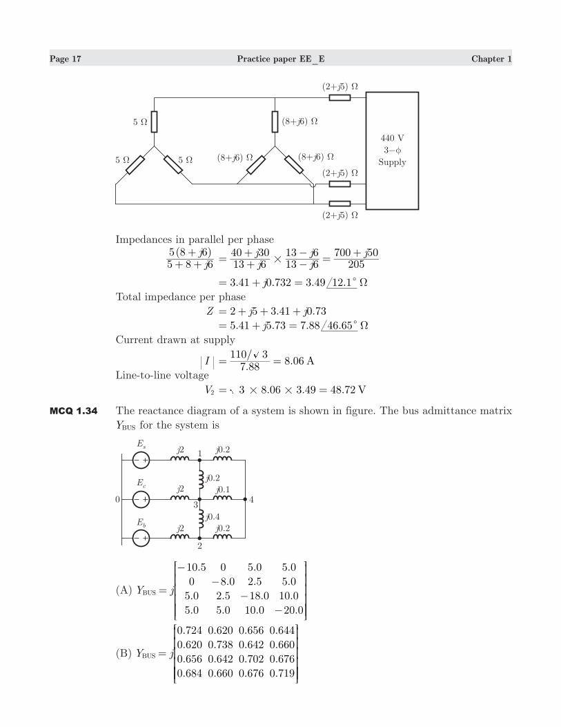
MCQ 1.34 The reactance diagram of a system is shown in figure. The bus admittance matrix
YBUS for the system is
(A)
.
.
.
.
.
.
.
.
.
.
.
.
.
.
Y j
10 5
0
5 0
5 0
0
8 0
2 5
5 0
5 0
2 5
18 0
10 0
5 0
5 0
10 0
20 0
BUS =
−
−
−
−
R
T
SSSSSS
V
X
WWWWWW
(B)
.
.
.
.
.
.
.
.
.
.
.
.
.
.
.
.
Y j
0 724
0 620
0 656
0 684
0 620
0 738
0 642
0 660
0 656
0 642
0 702
0 676
0 644
0 660
0 676
0 719
BUS =
R
T
SSSSSS
V
X
WWWWWW
Page 18 Practice paper EE_E Chapter 1
(C)
.
.
.
.
.
.
.
.
.
.Y j
10 5
0
5 0
5 0
0
8 0
0
5 0
5 0
0
18 0
10 0
0
5 0
10 0
0
BUS =
−
−
−
R
T
SSSSSS
V
X
WWWWWW
(D) .
.
.
.
.
.
.
.
.
.
.
Y jj
10
0
0 5
0 5
0
2 5
8
0 5
0 5
8
0 18
0 1
0 5
0 5
0 1
0 5
BUS =
−
−
−
−
R
T
SSSSSS
V
X
WWWWWW
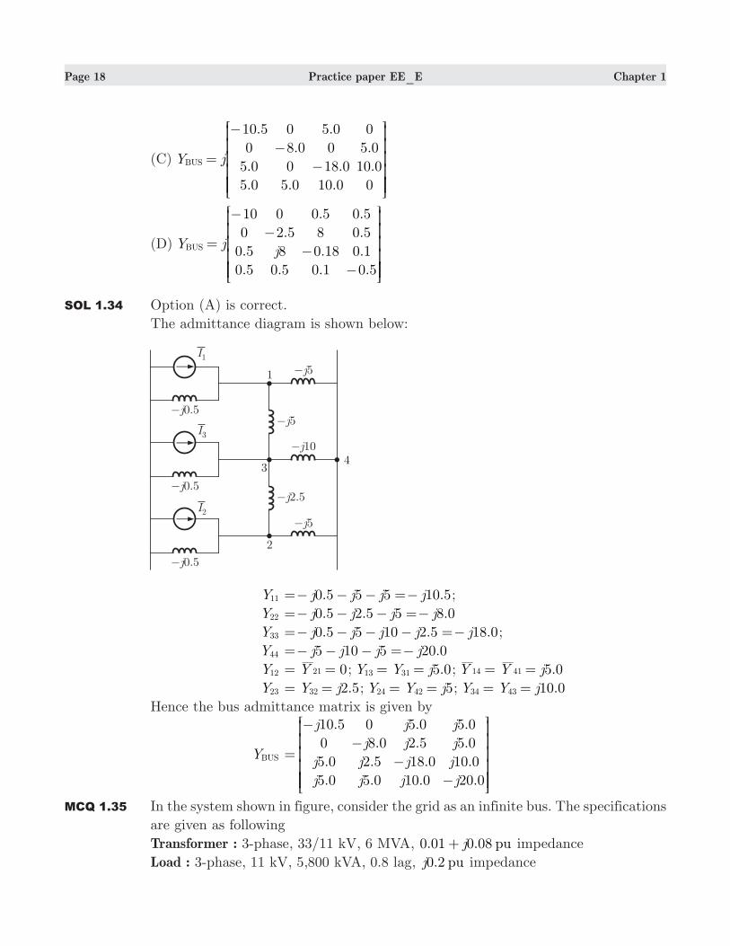
SOL 1.34 Option (A) is correct.
The admittance diagram is shown below:
Y11 . .j j j j0 5 5 5 10 5=− − − =− ;
Y22 0.5 2.5 5 8.0j j j j=− − − =−
Y33 . . .j j j j j0 5 5 10 2 5 18 0=− − − − =− ;
Y44 .j j j j5 10 5 20 0=− − − =−
Y12 Y 021= = ; 5.0Y Y j13 31= = ; .Y Y j5 014 41= =
Y23 2.5Y j32= = ; 5Y Y j24 42= = ; 10.0Y Y j34 43= =
Hence the bus admittance matrix is given by
YBUS
.
.
.
.
.
.
.
.
.
.
.
.
.
.
j
j
j
j
j
j
j
j
j
j
j
j
j
j
10 5
0
5 0
5 0
0
8 0
2 5
5 0
5 0
2 5
18 0
10 0
5 0
5 0
10 0
20 0
=
−
−
−
−
R
T
SSSSSS
V
X
WWWWWW
MCQ 1.35 In the system shown in figure, consider the grid as an infinite bus. The specifications
are given as following
Transformer : 3-phase, 33/11 kV, 6 MVA, 0.01 0.08 puj+ impedance
Load : 3-phase, 11 kV, 5,800 kVA, 0.8 lag, 0.2 puj impedance
Page 19 Practice paper EE_E Chapter 1
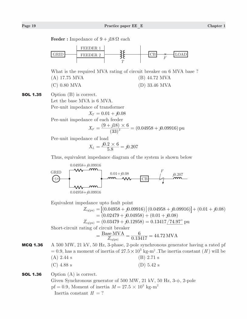
Feeder : Impedance of 9 18j Ω+ each
What is the required MVA rating of circuit breaker on 6 MVA base ?
(A) 17.75 MVA (B) 44.72 MVA
(C) 0.80 MVA (D) 33.46 MVA
SOL 1.35 Option (B) is correct.
Let the base MVA is 6 MVA.
Per-unit impedance of transformer
XT . .j0 01 0 08= +
Per-unit impedance of each feeder
XF ( )
( )(0.04958 0.09916) pu
jj
33
9 18 62#
=+
= +
Per-unit impedance of load
XL ..
.j
j5 8
0 2 60 207#= =
Thus, equivalent impedance diagram of the system is shown below
Equivalent impedance upto fault point
Z ( )eq pu ( . . ) ( . . ) (0.01 0.08)j j j0 04958 0 09916 0 04958 0 09916= + + + +8 B ( . . ) ( . . )j j0 02479 0 04958 0 01 0 08= + + +
Z ( )eq pu (0.03479 0.12958) 0.13417 . puj 74 97c= + =
Short-circuit rating of circuit breaker
.
44.72Base MVA MVAZ 0 13417
6( )eq pu
= = =
MCQ 1.36 A 500 MW, 21 kV, 50 Hz, 3-phase, 2-pole synchronous generator having a rated pf
= 0.9, has a moment of inertia of 27.5 103# kg-m2 .The inertia constant (H ) will be
(A) 2.44 s (B) 2.71 s
(C) 4.88 s (D) 5.42 s
SOL 1.36 Option (A) is correct.
Given Synchronous generator of 500 MW, 21 kV, 50 Hz, 3-φ, 2-pole
0.9pf = , Moment of inertia 27.5 10M 3#= kg-m2
Inertia constant H ?=
Page 20 Practice paper EE_E Chapter 1
Generator rating in MVA
G .
500 555.56cosP
0 9MW MVA
φ= = =
N 30002
120 50pole
120 f# #= = = rpm
Stored K.E 221
21
60M M
N22
ω π= = b l 27.5 10
21
602 3000 MJ3
# # ##π= b l
1357.07 MJ=
Inertia constant ( )H Rating of Generator (MVA)
Stored K.E=
H ..
555 561357 07=
2.44 sec=
MCQ 1.37 The forward-path transfer function of a ufb system is
( )G s ( )( )( )
( )
s s s
K s
1 4 1
22=+ + −
+
The range of K , that will make the system stable, is
(A) 12 2K< <− (B) 33 2K< <−
(C) 2K > (D) Unstable
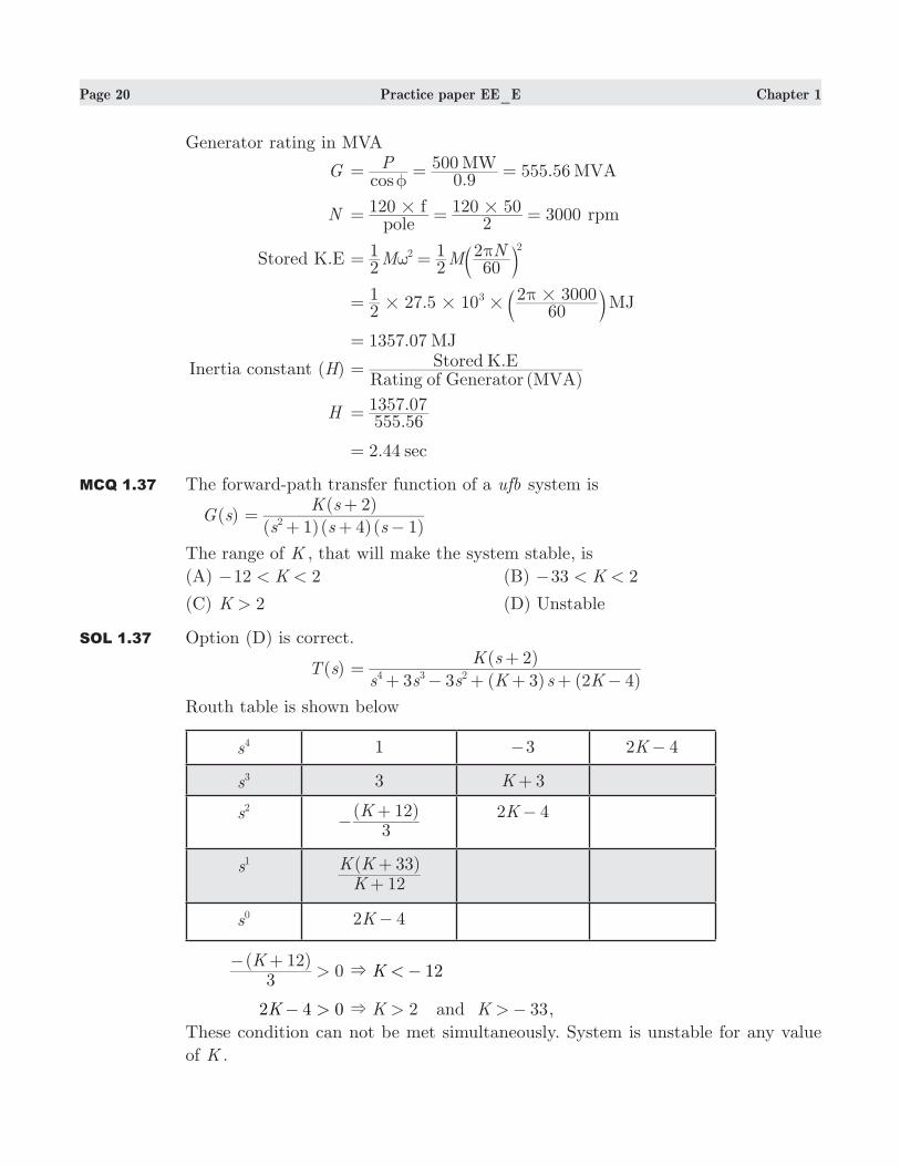
SOL 1.37 Option (D) is correct.
( )T s ( ) ( )
( )
s s s K s K
K s
3 3 3 2 4
24 3 2=+ − + + + −
+
Routh table is shown below
s4 1 3− 2 4K−
s3 3 3K+
s2 ( )K3
12−
+ 2 4K−
s1 ( )KK K
1233
++
s0 2 4K−
( )
0K
312>
− + 12K <& −
2 4 0K >− 2K >& and 33K >− ,
These condition can not be met simultaneously. System is unstable for any value
of K .
Page 21 Practice paper EE_E Chapter 1
MCQ 1.38 Consider the following system
a. ( )T s ( )( )s s3 6
5=+ +
b. ( )T s ( )( )
( )s s
s
10 2010 7
=+ +
+
c. ( )T s s s6 44
202
=+ +
d. ( )T s s
s
92
2=
+
+
e. ( )T s ( )
( )
s
s
10
52
=+
+
Consider the following response
1. Over damped 2. Under damped
3. Under damped 4. Critically damped
The correct match is
1 2 3 4
(A) a c d e
(B) b a d e
(C) c a e d
(D) c b e d
SOL 1.38 Option (A) is correct.
1. Over damped response (a, b)
Poles : Two real and different on negative real axis.
2. Under damped response (c)
Poles : Two complex in left half plane
Poles : Two complex in left half plane
3. Undamped response (d)
Poles : Two imaginary
4. Critically damped (e)
Poles : Two real and same on negative real axis.
MCQ 1.39 A PMMC instrument has full-scale deflection current of 100 µA and a coil resistance
of 1 kΩ. The value of required shunt resistance to convert the instrument into an
ammeter with a full scale deflection current of 100 mA is Rsh1. The same instrument
is converted into an ammeter with a full scale deflection current of 1 mA by using
a shunt resistor Rsh2. The ratio
RR
sh
sh
2
1 approximately equals to
(A) 10 (B) 100
(C) 0.1 (D) 1
SOL 1.39 Option (A) is correct.
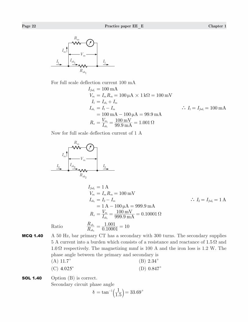
Page 22 Practice paper EE_E Chapter 1
For full scale deflection current 100 mA
I fsd1 100 mA=
Vm 100 1 100A k mVI Rm m µ Ω#= = =
I1 I Ish m1= +
Ish1 I Im1= − 100I I mAfsd1 1
` = =
100 100 99.9mA A mAµ= − =
Rs .1.001
mAmV
IV
99 9100
sh
m
1
1 Ω= = =
Now for full scale deflection current of 1 A
I fsd2 1 A=
Vm 100 mVI Rm m= =
Ish2 I Im2= − 1I I Afsd2 2
` = =
1 100 999.9A A mAµ= − =
Rs .0.10001
mAmV
IV
999 9100
sh
m
2
Ω= = =
Ratio RR
sh
sh
2
1 .. 10
0 100011 001= =
MCQ 1.40 A 50 Hz, bar primary CT has a secondary with 300 turns. The secondary supplies
5 A current into a burden which consists of a resistance and reactance of .1 5Ω and
.1 0Ω respectively. The magnetizing mmf is 100 A and the iron loss is 1.2 W. The
phase angle between the primary and secondary is
(A) .11 7c (B) .2 34c
(C) .4 025c (D) .0 847c
SOL 1.40 Option (B) is correct.
Secondary circuit phase angle
δ .
.tan1 51 33 691
c= =− b l
Page 23 Practice paper EE_E Chapter 1
cos δ 3 .6 0.8cos 3 9 32c= = , and
or, sin δ 3 .6 .sin 3 9 0 555c= =
Turn ratio Kt NN
1300 300
p
s= = =
Magnetizing current
Im 90sinMagneti g
AN
mmf1
100p
= = =
Secondary circuit burden impedance ( . ) ( . ) .1 5 1 0 1 82 2 Ω= + =
Secondary induced voltage
Es 5 1.8 9 V#= =
Primary induced voltage
Ep 9E
300 300s= =
Loss component Iw iron lossEp
= ( / )
. 409 3001 2 A= =
Phase angle θ cos sinK I
I I180t s
m w
πδ δ
=−b l
. .180300 5
100 0 832 40 0 555#
# #π
= −b l 2.34c=
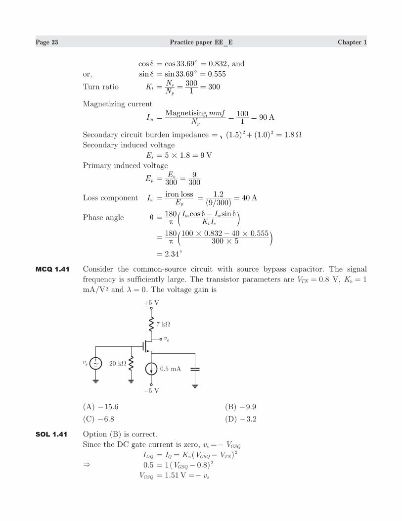
MCQ 1.41 Consider the common-source circuit with source bypass capacitor. The signal
frequency is sufficiently large. The transistor parameters are .V 0 8TN = V, K 1n =
mA/V2 and 0λ = . The voltage gain is
(A) .15 6− (B) .9 9−
(C) .6 8− (D) .3 2−
SOL 1.41 Option (B) is correct.
Since the DC gate current is zero, v Vs GSQ=−
IDQ ( )I K V VQ n GSQ TN2= = −
& 0.5 1( 0.8)VGSQ2= −
VGSQ 1.51 V vs= =−
Page 24 Practice paper EE_E Chapter 1
VDSQ 5 (0.5 )(7 ) ( 1.51) 3.01m k= − − − = V
The transistor is therefore biased in the saturation region.
The small-signal equivalent circuit is shown below
vo (7 )g v km gs=−
vgs , (7 )vvv
A g kii
ov m= = =−
gm 2 ( )K V Vn GS TN= −
2(1 )m= (1.51 0.8) 1.42− = mS
Av (1.42 )(7 )m k=− 9.9=−
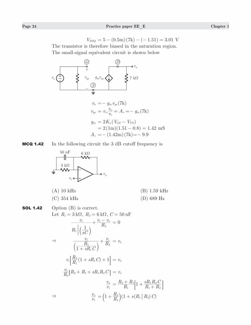
MCQ 1.42 In the following circuit the 3 dB cutoff frequency is
(A) 10 kHz (B) 1.59 kHz
(C) 354 kHz (D) 689 Hz
SOL 1.42 Option (B) is correct.
Let 3 kR1 Ω= , 6 kR2 Ω= , 50 nFC =
RsC
vRv v
1
i i o
1
2+−
b l 0=
&
sR CRv
Rv
1
i i
1
1 2
+
+b l vo=
( )vRR
sR C1 1i1
21+ +: D vo=
RvR R sR R Ci
12 1 1 2+ +6 @ vo=
vvi
o R
R RR RsR R C1
1
2 1
1 2
1 2=+
++: D
& vvi
o (1 ( ) )RR
s R R C11
21 2= + +b l
Page 25 Practice paper EE_E Chapter 1
f dB3 ( )R R C2
1
1 2π=
( ) (
1.59 kHz2 50
12 2
13k 6k n k)50nπ π
= = =
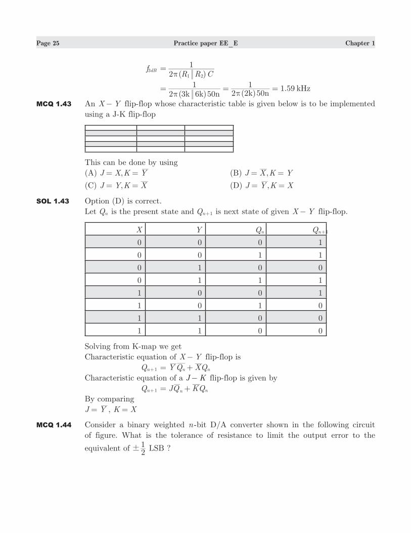
MCQ 1.43 An X Y− flip-flop whose characteristic table is given below is to be implemented
using a J-K flip-flop
This can be done by using
(A) ,J X K Y= = (B) ,J X K Y= =
(C) ,J Y K X= = (D) ,J Y K X= =
SOL 1.43 Option (D) is correct.
Let Qn is the present state and Qn 1+ is next state of given X Y− flip-flop.
X Y Qn Qn 1+
0 0 0 1
0 0 1 1
0 1 0 0
0 1 1 1
1 0 0 1
1 0 1 0
1 1 0 0
1 1 0 0
Solving from K-map we get
Characteristic equation of X Y− flip-flop is
Qn 1+ YQ XQn n= +
Characteristic equation of a J K− flip-flop is given by
Qn 1+ JQ KQn n= +
By comparing
J Y= , K X=
MCQ 1.44 Consider a binary weighted n -bit D/A converter shown in the following circuit
of figure. What is the tolerance of resistance to limit the output error to the
equivalent of 21
! LSB ?
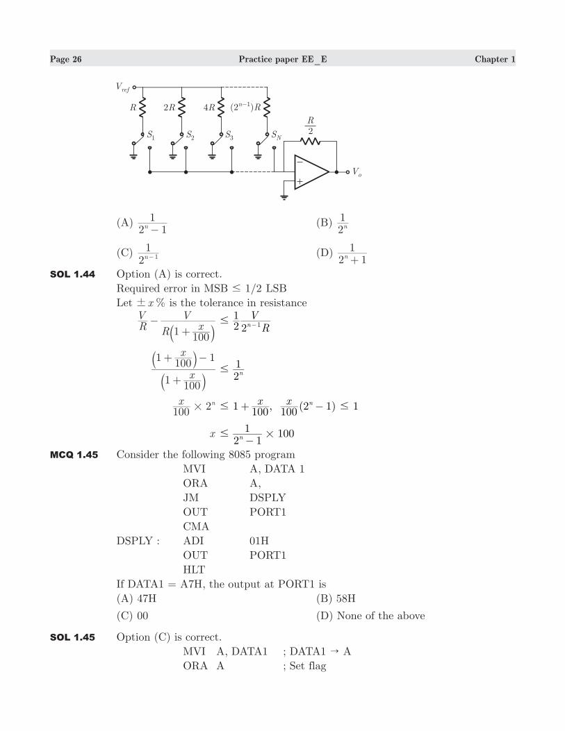
Page 26 Practice paper EE_E Chapter 1
(A) 2 1
1n−
(B) 21n
(C) 21n 1− (D)
2 11n+
SOL 1.44 Option (A) is correct.
Required error in MSB /1 2# LSB
Let %x! is the tolerance in resistance
RV
R xV
1100
−+a k R
V21
2n 1# −
x
x
1100
1100
1
+
+ −
aa
kk
21n#
2x100
n# 1 , (2 1) 1x x
100 100n
# #+ −
x 1002 1
1n# #−
MCQ 1.45 Consider the following 8085 program
MVI A, DATA 1
ORA A,
JM DSPLY
OUT PORT1
CMA
DSPLY : ADI 01H
OUT PORT1
HLT
If DATA1 = A7H, the output at PORT1 is
(A) 47H (B) 58H
(C) 00 (D) None of the above
SOL 1.45 Option (C) is correct.
MVI A, DATA1 ; DATA1 " A
ORA A ; Set flag
Page 27 Practice paper EE_E Chapter 1
JM DSPLY ; If negative jump to DSPLY
OUT PORT1 ; A " PORT1
DSPLY : CMA ; Complament A
ADI 01H ; A + 1 " A
OUT PORT1 ; A " PORT1
HLT
This program displays the absolute value of DATA1. If DATA is negative, it
determine the 2’s complements and display at PORT1.
MCQ 1.46 The system equations 6x y z+ + = , 2 3 10x y z+ + = , 2 12x y zλ+ + = is
inconsistent, if λ is
(A) 3 (B) 3−
(C) 0 (D) None of these
SOL 1.46 Option (A) is correct.
Equation xA B= is consistent only if ( ) ( )A A B:ρ ρ=
Otherwise system is said to be inconsistent i.e. possesses no solution. Now,
[ : ]A B
:
:
:
1
1
1
1
2
2
1
3
6
10
12λ
=
R
T
SSSS
V
X
WWWW
1
1
1
1
1
2
1
2
1
6
4
2λ
=
−
R
T
SSSS
V
X
WWWW
R R
R R
R
R
2 1
3 1
2
3
&
&
−
−f p
1
0
0
1
1
0
1
2
3
6
4
2λ
=
−
R
T
SSSS
V
X
WWWW ( )R R R3 2 3&−
& ( : )A Bρ 3=
As one of the minor 0
1
0
0
1
1
0
6
4
2
!
Now, system is inconsistent if
( )Aρ ( : )A B! ρ i.e. ( ) 3A !ρ
It is possible only when 3 0λ− = i.e. 3λ =
MCQ 1.47 For the differential equation x ydx
dy 2= − given that
:x 0 0.2 0.4 0.6
:y 0 0.02 0.0795 0.1762
Using Milne predictor-correction method, the y at next value of x is
(A) 0.2498 (B) 0.3046
(C) 0.4648 (D) 0.5114
SOL 1.47 Option (B) is correct.
Page 28 Practice paper EE_E Chapter 1
:x 0 0.2 0.4 0.6
On calculation we get
( )f x x y2= −
( )f x1 .0 1996=
( )f x2 .0 3937=
( )f x3 .0 5689=
Using predictor formula
y( )p4 (2 2 )y h f f f
34
0 1 2 3= + − +
Here 0.2h =
y( )p4 . [ (. ) (. ) (. )]0
30 8 2 1996 3937 2 5689= + − +
y( )c4 ( 4 ),y h f f f
3*
2 2 3 3= + − +
f *4 ( , ) (. , . ) .f x y f 8 0 3049 07070( )p
4 4= = =
y( )c4 . [. (. ) . ] .0795
302 3937 4 5689 7070 3046= + + + =
Statement for Question 48-49 :
A single phase half-bridge inverter is operated from a 24 V source and supplies
power to a resistive load.
MCQ 1.48 Total harmonic distortion(THD) is
(A) 48.4% (B) 19.8%
(C) 60% (D) 28%
SOL 1.48 Option (A) is correct.
RMS value of fundamental component is
V rms1 10.8 VV
2
2 dc
π= = 24V Vdc =
RMS harmonic voltage V, ,
/
nn
2
3 5 7
1 2
rms=
3
=; E/
[12 (10.8) ]V V /rms0
212 2 2 1 2= − = −
5.23 V=
Total harmonic distortion (THD)
THD V
V1,
/
rmsn
n1
2
2 3
1 2
rms=
3
=; E/
V
V V
1
0
2
1
2
rms
rms
=-
THD .
. . . %10 85 23 0 484 48 4= = =
MCQ 1.49 The harmonic factor and the distortion factor for the lowest order harmonic are
respectively

Page 29 Practice paper EE_E Chapter 1
(A) 20%, 2.22% (B) 7.68%, 33.33%
(C) 33.33%, 3.7% (D) 35.88%, 3.98%
SOL 1.49 Option (C) is correct.
We have, RMS value of fundamental component
V rms1 10.8 VV
2
2 dc
π= =
The lowest harmonic is third harmonic. Third harmonic voltage is
V rms3 3.6 VV
3 2
2 dc
π= = 24V Vdc =
HF for the third harmonic
HF3 .. 33.33%
VV
10 83 6
rms
rms
1
3= = =
DF of the third harmonic
DF3 ( / )
.. /
0.037 3.7%VV 3
10 83 6 9
rms
rms
1
32
= = = =
Statement for Q. 50-51
A power plant consisting of two generations G1 and G2 supplies a total load of 450
MW. The fuel costs of two generations G1 and G2 are C1 and C2 respectively, given
as following
C1 .P P100 2 0 0051 12= + +
C2 .P P200 2 0 012 22= + +
where P1 and P2 are the generation in MW of G1 and G2 respectively.
MCQ 1.50 The economic load scheduling of the two units will be
(A) 225
225
P
P
MW
MW
1
2
=
=
(B) P
P
180
270
MW
MW
1
2
=
=
(C) P
P
300
150
MW
MW
1
2
=
=
(D) P
P
240
210
MW
MW
1
2
=
=
SOL 1.50 Option (C) is correct.
The incremental fuel cost of G1
dPdC
1
1 2 0.01P1= +
The incremental fuel cost of G2
dPdC
1
2 2 0.02P2= +
For optimum load division the two incremental costs should be equal, that is
dPdC
1
1 dPdC
1
2=
. P2 0 01 1+ . P2 0 02 2= +
Page 30 Practice paper EE_E Chapter 1
P1 P2 2= ...(i)
Total load by the two generators
P P1 2+ 450= ...(ii)
From of equation (i) and (ii), we get
P1 300 , 150MW P MW2= =
MCQ 1.51 The incremental fuel cost of the power plant in Rs/MWh will be
(A) 4.25 Rs/MWh (B) 10 Rs/MWh
(C) 5 Rs/MWh (D) 6.5 Rs/MWh
SOL 1.51 Option (C) is correct.
The incremental fuel cost of G1
dPdC
1
1 2 0.01P1= +
2 0.01 300 5 /Rs MWh#= + =
The incremental fuel cost of G2
dPdC
1
2 2 0.02P2= +
2 0.02 150 5 /Rs MWh#= + =
Hence the incremental fuel cost of the plant for most economic operation is 5 Rs/
MWh.
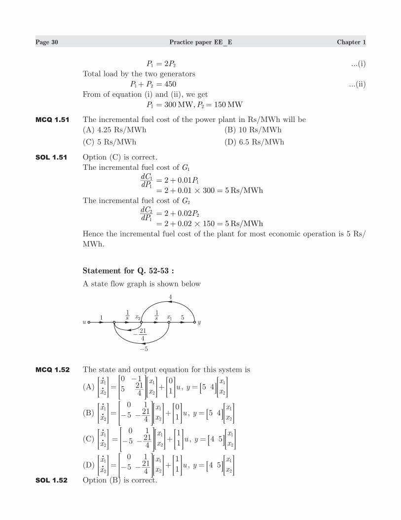
Statement for Q. 52-53 :
A state flow graph is shown below
MCQ 1.52 The state and output equation for this system is
(A) x
x
x
xu
0
5
1
421
0
11
2
1
2=
−+
o
o> > > >H H H H , y
x
x5 4
1
2= 8 >B H
(B) x
x
x
xu
0
5
1
421
0
11
2
1
2= − − +
o
o> > > >H H H H , y
x
x5 4
1
2= 8 >B H
(C) x
x
1
2
o
o> H x
xu
0
5
1
421
1
11
2= − − +> > >H H H , y
x
x4 5
1
2= 8 >B H
(D) x
x
x
xu
0
5
1
421
1
11
2
1
2= − − +
o
o> > > >H H H H , y
x
x4 5
1
2= 8 >B H
SOL 1.52 Option (B) is correct.

Page 31 Practice paper EE_E Chapter 1
x2o 5s x u421
2 2=− − + ,
x1o x2= ,
y 5 4x x1 2= +
x
x
1
2
o
o> H x
xu
0
5
1
421
0
11
2= − − +> > >H H H , y
x
x5 4
1
2= 8 >B H
MCQ 1.53 The system is
(A) Observable and controllable (B) Controllable only
(C) Observable only (D) None of the above
SOL 1.53 Option (B) is correct.
OM C
CA
5
20
4
1= =
−> >H H
det 0OM = . Thus system is not observable
CM B AB0
1
1
421= = −8 >B H
det 1CM =− . Thus system is controllable.
Statement for Q. 54-55:
Two generators G1 and G2 are to be operated in parallel to deliver a total current
of 60 A. Generator G1 has a terminal voltage of 280 V on no-load and 240 V when
supplying 40 A current. Similarly the second generator has a voltage of 300 V when
on no-load and 240 V when supplying 50 A of current.
MCQ 1.54 The output voltage of each generator will be
(A) 240 V (B) 238.2 V
(C) 271.7 V (D) 256.4 V
SOL 1.54 Option (D) is correct.
Generator G1:
Voltage drop per ampere 1 A40
280 240= − =
Let output current is IG1, then output voltage will be
VG1 280 1 IG1#= −
Generator G2:
Voltage drop per ampere 1.2 A50
300 240= − =
Let output current is IG2, then output voltage will be
VG2 1. I300 2 G2#= −
For parallel operation, output of each generator would be same i.e.
VG1 VG2=
Page 32 Practice paper EE_E Chapter 1
280 1 IG1#− 1. I300 2 G2#= −
or .I I1 2G G1 2− + 20= ...(i)
Total current delivered
I IG G1 2+ 60= ...(ii)
Solving equation (i) and (ii) we get
IG1 23.6 A= and 36. AI 4G2
=
So the output voltage
VG1 256.4V VG2= =
MCQ 1.55 The output power PG1 and PG2
delivered by generator G1 and G2 will be
(A) .6 .P P5 8 7kW, kWG G1 2= = (B) .6P P9 12kW, kWG G1 2
= =
(C) 9.3P P kWG G1 2= = (D) 6 9.3P PkW, kWG G1 2
= =
SOL 1.55 Option (D) is correct.
PG1 256.4 23.6 6.05V I kWG G1 1 #= = =
PG2 256.4 . .V I 36 4 9 3 kWG G2 2 #= = =
Q.56 TO Q.60 CARRY ONE MARK EACH
MCQ 1.56 Which one of the following is the Antonym of the word FEARLESS ?
(A) intrepid (B) craven
(C) vacillate (D) oscillate
SOL 1.56 Correct option is (B)
MCQ 1.57 Which one of the following is the synonym of the word CONTROVERSIAL ?
(A) pulse (B) polemic
(C) record (D) integrity
SOL 1.57 Correct option is (B)
MCQ 1.58 One of the four words given in the four options does not fit the set of words. The
odd word from the group, is
(A) Break (B) Hiatus
(C) Pause (D) End
SOL 1.58 Correct option is (D)
MCQ 1.59 A pair of CAPITALIZED words shown below has four pairs of words. The pair
of words which best expresses the relationship similar to that expressed in the
capitalized pair, is
ENTHUSIASTIC : FANATICAL
(A) Frugal : Miserly (B) Faithful : Kind
(C) Admonish : Warn (D) Virtuous : Wholesome

Page 33 Practice paper EE_E Chapter 1
SOL 1.59 Correct option is (A)
MCQ 1.60 In the following sentence, a part of the sentence is left unfinished. Four different
ways of completing the sentence are indicated. The best alternative among the
four, is
No doubt, it was our own government but it was being run on borrowed ideas,
using................solutions.
(A) worn out (B) second hand
(C) impractical (D) appropriate
SOL 1.60 Correct option is (B)
Q.61 TO Q.65 CARRY TWO MARK EACH
MCQ 1.61 After striking the floor, a Tennis ball rebounds to 4/5th of the height from which
it has fallen. What will be the total distance that it travels before coming to rest if
it has been gently dropped from a height of meters90 . ?
(A) 675 metres (B) metres810
(C) metres920 (D) 1020 metres
SOL 1.61 Correct option is (B).
The first drop is 9 metres0 . After thus the ball will rise by metres72 and fall by
metres72 , now this process will be continue in the form of an infinite GP with
common ratio .0 8 and first term 72.
The required answer will be got by
90 2.1 0 8
72= +−b l
MCQ 1.62 The ratio of cost price and marked price of a cell phone is :2 3 and ratio of profit
percentage and discount percentage is :3 2.What is the discount percentage ?
(A) %8 (B) %12
(C) . %16 66 (D) 19.5%
SOL 1.62 Correct option is (C).
CP : MP :x x2 3=
& Profit x=
%^ h profit : %^ h discount :3 2=
Let CP 200, SP 300= =
But x x1003 200
1002 300# #+ 100=
& x . %8 33=
Discount = x2 . %16 66=
MCQ 1.63 If prices are reduced 2 %0 and sales increase %15 , what is the net effect on gross
Page 34 Practice paper EE_E Chapter 1
receipts ?
(A) They increase by %8 (B) They decrease by %8
(C) They remain the same (D) They increase by %10
SOL 1.63 Correct option is (B).
Let original price p= , and original sales s= . Therefore, original gross receipts
ps= . Let new price .80p0= , and new sales 1. s15= . Therefore, new gross receipts
.92ps0= . Gross receipts are only 9 %2 of what they were.
MCQ 1.64 Reduction of %20 in the price of sugar enables a housewife to purchase kg5 more
for Rs. 250. What is the original price per kg of sugar ?
(A) Rs. 10 per kg (B) Rs. .12 5 per kg
(C) Rs. 15 per kg (D) Rs. 21 per kg
SOL 1.64 Correct option is (B).
Reduction in price increase in amount
%2051.b l % kg
41 25 5- =^ h
It means original amount of sugar needed 5 4 2 kg0#= =
Original price of sugar .1 . .Rs per kg20250 2 5= =
MCQ 1.65 A milkman purchases the milk at Rs. x per litre and sells it at Rs. x2 per litre
still he mixes 1 litres water with every 5 litres of pure milk. What is the profit
percentage ?
(A) 11 %5 (B) 1 . %27 5
(C) %132 (D) %140
SOL 1.65 Correct option is (D).
Let the cost price of 1 litre pure milk be Re. 1, then
.
.
litres milk
litres water
CP Rs
CP RsCP
5
1
5
0"
""
=
=
^ hh* 4 .Rs 5= only
and 6 litre mixture 2SP 6" " # .1Rs 2=
Profit 1005
12 55
700#= − = %140=
ANSWER KEY

Page 35 Practice paper EE_E Chapter 1
1. 2. 3. 4. 5, 6. 7. 8. 9. 10. 11. 12. 13. 14. 15.
D A D D A D C C C B A A D D A
16. 17. 18. 19. 20. 21. 22. 23. 24. 25. 26. 27. 28. 29. 30.
A B C B A B B C A A B C B B D
31. 32. 33. 34. 35. 36. 37. 38. 39. 40. 41. 42. 43. 44. 45.
A B B A B A D A A B B B D A C
46. 47. 48. 49. 50. 51. 52. 53. 54. 55. 56. 57. 58. 59. 60.
A B A C C C B B D D B B D A B
61. 62. 63. 64. 65. . .
B C B B D