
Opticalamplifiers - Login ERC WEBopti500.cian-erc.org/opti500/pdf/25...
41
Transcript of Opticalamplifiers - Login ERC WEBopti500.cian-erc.org/opti500/pdf/25...
Page 2 / 40 Cédric Ware <[email protected]>
2011
Document License
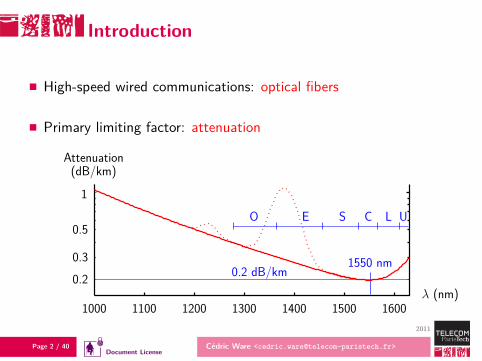
Introduction
High-speed wired communications: optical fibers
Primary limiting factor: attenuation
λ (nm)
(dB/km)
1550 nm
C L
Attenuation
0.2 dB/km
E SO U1
1000 1100 1200 1300 1500
0.20.3
1600
0.5
1400
Page 3 / 40 Cédric Ware <[email protected]>
2011
Document License
Introduction
Avoid signal regenerators (O-E-O bulky; all-optical not mature)
⇒ Optical amplifierssince 1993: long-distance transmissions2000s: metropolitan networksnow: extended-range access networksenvisioned: all-optical signal processing
⇒ Transmission bandwidth = amplifiers’ gain bandwidth
Page 4 / 40 Cédric Ware <[email protected]>
2011
Document License
Optical amplification
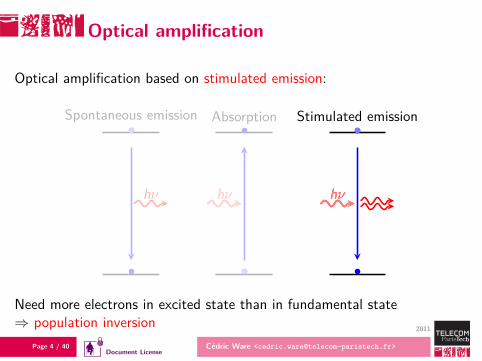
Optical amplification based on stimulated emission:
hν
Spontaneous emission
hνhν
Absorption
hνhν
Stimulated emission
Need more electrons in excited state than in fundamental state⇒ population inversion
Page 5 / 40 Cédric Ware <[email protected]>
2011
Document License
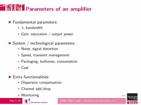
Parameters of an amplifier
Fundamental parameters:λ, bandwidthGain, saturation / output power
System / technological parameters:Noise, signal distortionSpeed, transient managementPackaging, bulkiness, consumptionCost
Extra functionalities:Dispersion compensationChannel add/dropMonitoring
Page 6 / 40 Cédric Ware <[email protected]>
2011
Document License
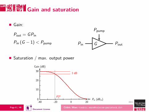
Gain and saturation
Gain:
Pout = GPin
Pin (G − 1) < Ppump Pin G Pout
Ppump
Saturation / max. output power
Gain (dB)
Pin (dBm)
3 dB
P satin
20
20
10
0
30
-40 -20 0
Page 7 / 40 Cédric Ware <[email protected]>
2011
Document License
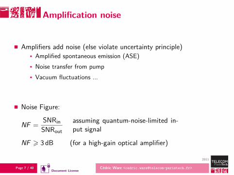
Amplification noise
Amplifiers add noise (else violate uncertainty principle)Amplified spontaneous emission (ASE)Noise transfer from pumpVacuum fluctuations ...
Noise Figure:
NF =SNRinSNRout
assuming quantum-noise-limited in-put signal
NF > 3 dB (for a high-gain optical amplifier)
Page 8 / 40 Cédric Ware <[email protected]>
2011
Document License
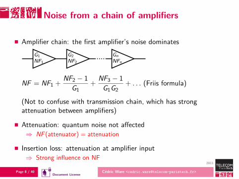
Noise from a chain of amplifiers
Amplifier chain: the first amplifier’s noise dominatesG1NF1
G2NF2
GnNFn
NF = NF1 +NF2 − 1
G1+
NF3 − 1G1G2
+ . . . (Friis formula)
(Not to confuse with transmission chain, which has strongattenuation between amplifiers)
Attenuation: quantum noise not affected⇒ NF (attenuator) = attenuation
Insertion loss: attenuation at amplifier input⇒ Strong influence on NF
Page 9 / 40 Cédric Ware <[email protected]>
2011
Document License
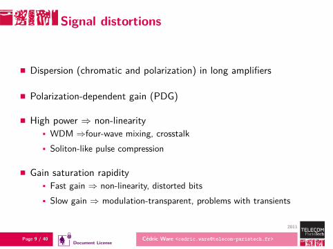
Signal distortions
Dispersion (chromatic and polarization) in long amplifiers
Polarization-dependent gain (PDG)
High power ⇒ non-linearityWDM ⇒four-wave mixing, crosstalkSoliton-like pulse compression
Gain saturation rapidityFast gain ⇒ non-linearity, distorted bitsSlow gain ⇒ modulation-transparent, problems with transients
Page 10 / 40 Cédric Ware <[email protected]>
2011
Document License
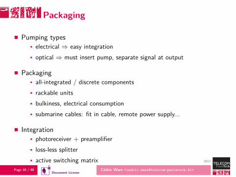
Packaging
Pumping typeselectrical ⇒ easy integrationoptical ⇒ must insert pump, separate signal at output
Packagingall-integrated / discrete componentsrackable unitsbulkiness, electrical consumptionsubmarine cables: fit in cable, remote power supply...
Integrationphotoreceiver + preamplifierloss-less splitteractive switching matrix
Page 11 / 40 Cédric Ware <[email protected]>
2011
Document License
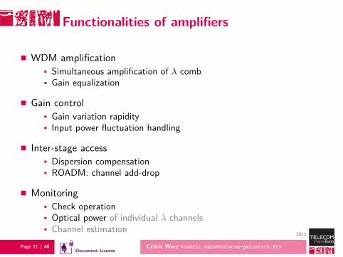
Functionalities of amplifiers
WDM amplificationSimultaneous amplification of λ combGain equalization
Gain controlGain variation rapidityInput power fluctuation handling
Inter-stage accessDispersion compensationROADM: channel add-drop
MonitoringCheck operationOptical power of individual λ channelsChannel estimation
Page 12 / 40 Cédric Ware <[email protected]>
2011
Document License
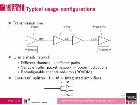
Typical usage configurations
Transmission line
Emitter
Booster PreamplifierIn-line
Receiver
... in a mesh networkDifferent channels → different pathsVariable traffic, packet network ⇒ power fluctuationsReconfigurable channel add-drop (ROADM)
“Loss-less” splitter: 1× N + integrated amplifiers
Page 13 / 40 Cédric Ware <[email protected]>
2011
Document License
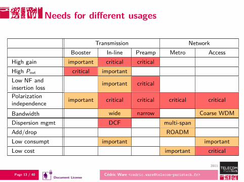
Needs for different usages
Transmission NetworkBooster In-line Preamp Metro Access
High gain important critical criticalHigh Pout critical importantLow NF andinsertion loss
important critical
Polarizationindependence important critical critical critical critical
Bandwidth wide narrow Coarse WDMDispersion mgmt DCF multi-spanAdd/drop ROADMLow consumpt important importantLow cost important critical
Page 14 / 40 Cédric Ware <[email protected]>
2011
Document License
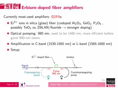
Erbium-doped fiber amplifiers
Currently most-used amplifiers: EDFAs
Er3+ ions in silica (glass) fiber (codoped Al2O3, GeO2, P2O5...possibly TeO2 ou ZBLAN/fluoride → stronger doping)Optical pumping: 980 nm, used to be 1480 nm, more efficient beforegood 980-nm lasersAmplification in C-band (1530-1565 nm) or L-band (1565-1600 nm)Setup:
Pump980 nm Counterpropagating
pumpCopropagating
pump
Signal
IsolatorEr3+-doped fiber
Page 15 / 40 Cédric Ware <[email protected]>
2011
Document License
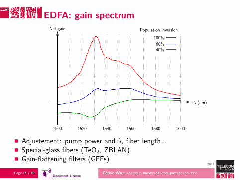
EDFA: gain spectrumPopulation inversionNet gain
λ (nm)
40%60%
1500 1520 1540 1560 1580 1600
100%
Adjustement: pump power and λ, fiber length...Special-glass fibers (TeO2, ZBLAN)Gain-flattening filters (GFFs)
Page 16 / 40 Cédric Ware <[email protected]>
2011
Document License
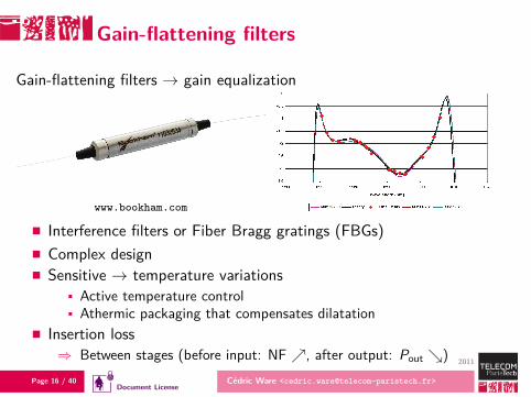
Gain-flattening filters
Gain-flattening filters → gain equalization
www.bookham.com
Interference filters or Fiber Bragg gratings (FBGs)Complex designSensitive → temperature variations
Active temperature controlAthermic packaging that compensates dilatation
Insertion loss⇒ Between stages (before input: NF ↗, after output: Pout ↘)
Page 17 / 40 Cédric Ware <[email protected]>
2011
Document License
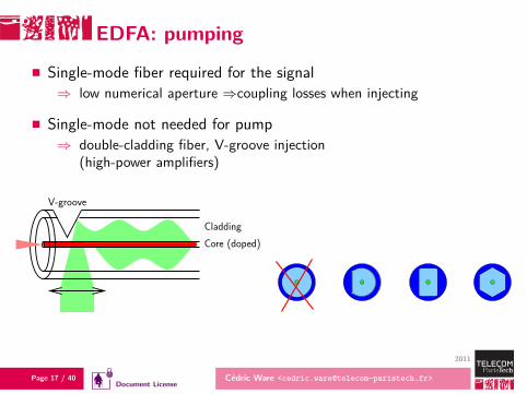
EDFA: pumping
Single-mode fiber required for the signal⇒ low numerical aperture ⇒coupling losses when injecting
Single-mode not needed for pump⇒ double-cladding fiber, V-groove injection
(high-power amplifiers)
Core (doped)Cladding
V-groove
Page 18 / 40 Cédric Ware <[email protected]>
2011
Document License
EDFA characteristics
C- or L-bandAll-fiber ⇒ low insertion lossGain up to 40 dB, Pout > 23 dBm, polarization-independentNF down to ∼ 3 dB (lab) ; 4–6 dB in practiceLong-lifetime excited states (few ms)⇒ gain = constant over each bit⇒ good linearity
Drawbacks:Optical pumping ⇒ complexSensitive to traffic fluctuations (on packet networks)
Page 19 / 40 Cédric Ware <[email protected]>
2011
Document License
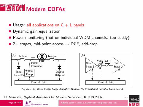
Modern EDFAs
Usage: all applications on C + L bandsDynamic gain equalizationPower monitoring (not on individual WDM channels: too costly)2+ stages, mid-point access → DCF, add-drop
ICTON 2006 115 Tu.C1.2
1-4244-0236-0/06/$20.00 ©2006 IEEE
Optical Amplifiers for Modern Networks David Menashe, Alex Shlifer and Uri Ghera
RED-C Optical Networks, Atidim Tech. Park, Bldg 3. P.O.B 58101, Tel-Aviv 61580, Israel Tel: (9723) 6476789, Fax: (9723) 6476990, e-mail: [email protected]
ABSTRACT Recent trends in optical networks, such as Reconfigurable Optical Add Drop Multiplexing (ROADM) and optical cross connects, require advanced optical amplifiers based on both Erbium Doped Fibre Amplifiers (EDFAs) and Raman technology. To address the dynamic nature of modern networks, EDFAs should provide broadband variable gain operation, flexible mid-stage access, fast transient response to dynamic events, and advanced spectral monitoring and control to adjust to changing spectral conditions in the network. An important supplement to EDFA technology is the use of Distributed Raman Amplification (DRA) to achieve transmission over multi-span Ultra Long Haul (ULH) links in all optical networks, as well as very high loss repeaterless links. Keywords: optical amplifiers, EDFAs, distributed Raman amplifiers, optical channel monitoring, ROADM.
1. INTRODUCTION The rapid growth of IP traffic, which now dominates most service provider networks, has placed new demands on the optical layer of the network. The unpredictable nature of the traffic, coupled with the need to provide multiple broadband services at ever decreasing cost, has led service providers to demand flexible reconfigurable optical networks which are self-managed and can seamlessly adjust to dynamic traffic conditions. In the short to intermediate term, this demand has led to the widespread interest in and deployment of Reconfigurable Optical Add Drop Multiplexing (ROADM), which allows individual wavelength to be dynamically and remotely dropped or added at sites along an optical link. In the longer term, Optical Cross Connect (OXCs), also known as high degree nodes, will be required to create all-optical mesh networks where different wavelengths traverse different and diverse paths within a multi-point mesh network. Additionally, enhanced protection and restoration capabilities are required at the optical layer to support carrier class Ethernet and other advanced services.
Being key components in any optical network, optical amplifiers need to support these new requirements. In particular, they are required to support: Broadband operation over a large dynamic range with respect to input/output power and gain: Flexible mid-stage access for advanced optical modules such as ROADM devices, Wavelength Blockers (WBs) and Dynamic Gain Equalizers (DGEs); Fast transient response to sudden dynamic changes in input power; and Detection of and adjustment to changes in spectral composition of the input signal. In addition, amplifiers should have minimum Noise Figure (NF) in order to enhance system OSNR and enable transmission over longer distances without electronic regeneration. In this respect, the use of DRA in conjunction with conventional EDFAs is a key enabler for ULH transmission and other demanding applications.
2. ADVANCED EDFA MODULES EDFAs have been widely deployed since the early 90’s, with the basic technology and components now being both mature and well understood [1]. The basic EDFA design consists of a length of Erbium Doped Fibre (EDF), pumped by a 980nm pump laser diode. The addition of input and output isolators and detectors, together with an electronic control unit, represents a single stage amplifier module, as shown in Fig. 1a. Such a module is typically operated in Automatic Gain Control (AGC) or Automatic Output Power Control (APC), where the input and output detectors supply the required feedback to the control unit, which in turn controls the pump power.
Figure 1. (a) Basic Single Stage Amplifier Module, (b) Broadband Variable Gain EDFA.
Isolator
EDF Pump Combiner
Isolator
980nm Pump
Input Detector
Output Detector
Control Unit
(a)
Gain Stage I
VOA GFF Gain
Stage II
Control Unit
(b)
D. Menashe, “Optical Amplifiers for Modern Networks”, ICTON 2006.
Page 20 / 40 Cédric Ware <[email protected]>
2011
Document License
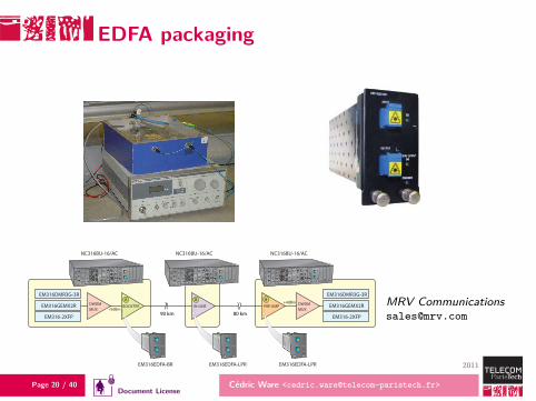
EDFA packaging
FDDatasheet
Media ConvertersRepeaters and Optimizers
Optical Amplifi ers
Overview
Fiber Driver® EM316EDFA modules provide a multi-function, low-noise, Erbium-Doped Fiber Amplifi er (EDFA) solution ideal for metro Dense Wavelength Division Multiplexing (DWDM) as well as single wavelength distance extension applications.
The EM316EDFA-BR and EM316EDFA-LPR are part of the Fiber Driver optical multi-service platform solution family. The EM316EDFA-BR is an optical booster extending transmission range. The EM316EDFA-LPR may be either an in-line repeater or a pre-amplifi er that can strengthen weak signals, optionally extending the link range as well. By performing two functions, the EM316EDFA-LPR also reduces some inventory requirements.
EM316DMR3G-3R
EM316GEMX2R
EM316-2XFP
DWDMMUX
BOOSTER IN-LINE PRE-AMP DWDMMUX
EM316DMR3G-3R
EM316GEMX2R
EM316-2XFP
OPTICAL OUTPUT
PWR/NMS
OUTPUT
INPUT
SD
OK
OPTICAL OUTPUT
PWR/NMS
OUTPUT
INPUT
SD
OK OPTICAL OUTPUT
PWR/NMS
OUTPUT
INPUT
SD
OK
90 km 80 km+9dBm
+4dBm
Long Haul Application
EM316EDFA-BR
A B B
NC316BU-16/AC
EM316EDFA-LPR EM316EDFA-LPR
NC316BU-16/ACNC316BU-16/AC
Features
Two models- EM316EDFA-BR (booster amplifi er) - EM316EDFA-LPR (in-line and pre-amplifi er)
Applications - Metro DWDM distance extension - Single wavelength distance extension
Automatic Gain Control (AGC)
Managed and non-managed operation
Advanced performance monitoring - Input and output power levels - Signal gain- Temperature- Supply voltage
Gain fl attering fi lters (GFF)
Manual (SNMP management) and automatic power shutdown
Status LEDs- Input power OK- Output power OK
Hot-swap support
Fiber Driver® two-slot and sixteen-slot chassis compatibility
Page 21 / 40 Cédric Ware <[email protected]>
2011
Document License
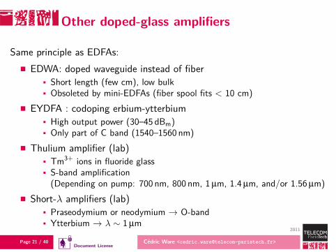
Other doped-glass amplifiers
Same principle as EDFAs:EDWA: doped waveguide instead of fiber
Short length (few cm), low bulkObsoleted by mini-EDFAs (fiber spool fits < 10 cm)
EYDFA : codoping erbium-ytterbiumHigh output power (30–45 dBm)Only part of C band (1540–1560 nm)
Thulium amplifier (lab)Tm3+ ions in fluoride glassS-band amplification(Depending on pump: 700 nm, 800 nm, 1µm, 1.4µm, and/or 1.56µm)
Short-λ amplifiers (lab)Praseodymium or neodymium → O-bandYtterbium → λ ∼ 1µm
Page 22 / 40 Cédric Ware <[email protected]>
2011
Document License
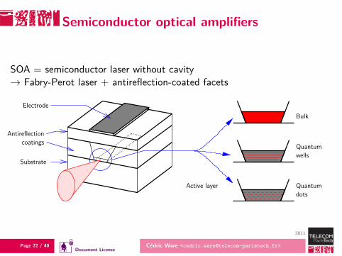
Semiconductor optical amplifiers
SOA = semiconductor laser without cavity→ Fabry-Perot laser + antireflection-coated facets
Substrate
Electrode
Antireflectioncoatings
dotsQuantum
wellsQuantum
Bulk
Active layer

Page 23 / 40 Cédric Ware <[email protected]>
2011
Document License
SOA packaging
SOA module:chip mounted on basebias current 200mA – 2 A (according to active layer volume)Peltier thermoelectric module → cooling, temperature controllensed fibers or microlenses
L. Spiekman, “Semiconductor optical amplifiers for reconfigurable optical networks”, J. OpticalNetworking 6 (11), Nov 2007.
Page 24 / 40 Cédric Ware <[email protected]>
2011
Document License
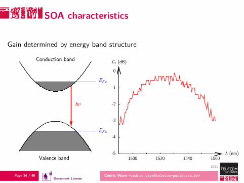
SOA characteristics
Gain determined by energy band structure
Valence band
Conduction band
hν
EF c
EF v
Gr (dB)
λ (nm)-5
-4
-3
-2
-1
0
1500 1520 1540 1560
Page 25 / 40 Cédric Ware <[email protected]>
2011
Document License
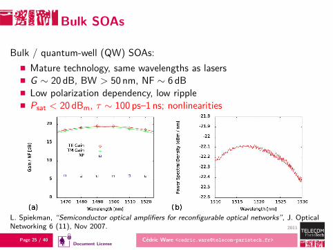
Bulk SOAs
Bulk / quantum-well (QW) SOAs:Mature technology, same wavelengths as lasersG ∼ 20 dB, BW > 50 nm, NF ∼ 6 dBLow polarization dependency, low ripplePsat < 20 dBm, τ ∼ 100 ps–1 ns; nonlinearities
L. Spiekman, “Semiconductor optical amplifiers for reconfigurable optical networks”, J. OpticalNetworking 6 (11), Nov 2007.
Page 26 / 40 Cédric Ware <[email protected]>
2011
Document License
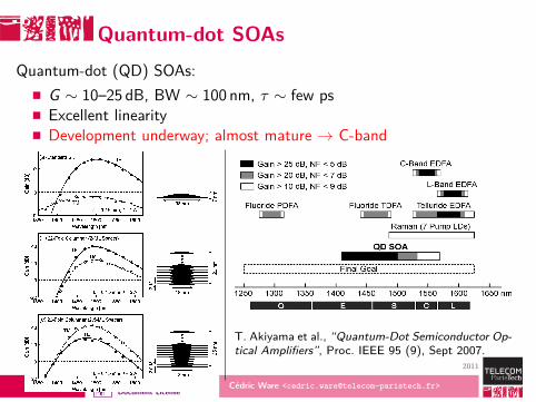
Quantum-dot SOAsQuantum-dot (QD) SOAs:
G ∼ 10–25 dB, BW ∼ 100 nm, τ ∼ few psExcellent linearityDevelopment underway; almost mature → C-band
T. Akiyama et al., “Quantum-Dot Semiconductor Op-tical Amplifiers”, Proc. IEEE 95 (9), Sept 2007.
Page 27 / 40 Cédric Ware <[email protected]>
2011
Document License
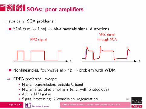
SOAs: poor amplifiers
Historically, SOA problems:
SOA fast (∼ 1 ns) ⇒ bit-timescale signal distortions
t t
through SOANRZ signal
NRZ signal
Nonlinearities, four-wave mixing ⇒ problem with WDM
⇒ EDFA preferred, except:Niche: transmissions outside C-bandNiche: integrated amplifiers (e. g. with photodiode)Active MZI gatesSignal processing: λ conversion, regeneration...
Page 28 / 40 Cédric Ware <[email protected]>
2011
Document License
SOAs: comeback
Currently, SOAs making a comeback:Long-distance transmissions changing techniques
Constant-envelope modulations (NRZ-xPSK)Packet networks ⇒ transients on packet timescales
Development of novel metro+access networksLow cost preferredCoarse WDM ⇒ less FWM, need wide bandwidthShorter distances/lower powers ⇒ small signals ⇒ SOAs ∼ linear“Extender-boxes” → long-range access networks (> 20 km)
Page 29 / 40 Cédric Ware <[email protected]>
2011
Document License
SOA improvements
Quantum-dot SOAs:Very wide bandwidthUltrafast electron transitions + wetting layer ⇒ gain is clamped
LOA: SOA + VCSELActive layer sandwiched between Bragg reflectors
⇒ Laser perpendicular to signal propagation⇒ Clamps carrier density ⇒ better linearity
Page 30 / 40 Cédric Ware <[email protected]>
2011
Document License
New SOA usages
“Novel functionalities” of the 1990s (nonlinear effects)All-optical signal processingWavelength conversionModulation format conversionRegenerationLogic gates
→ Still not widespread outside labs
Integration / use as on-off switchLoss-less splittersSwitching matricesRSOAs: replaces laser + modulator for wavelength-independent opticalnetwork units in access networks
Page 31 / 40 Cédric Ware <[email protected]>
2011
Document License
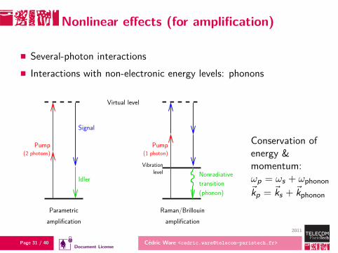
Nonlinear effects (for amplification)
Several-photon interactionsInteractions with non-electronic energy levels: phonons
Vibrationlevel
Pump
Signal
Virtual level
amplificationParametric
amplificationRaman/Brillouin
Nonradiative
(phonon)transition
Pump(2 photons) (1 photon)
Idler
Conservation ofenergy &momentum:ωp = ωs + ωphonon~kp = ~ks + ~kphonon
Page 32 / 40 Cédric Ware <[email protected]>
2011
Document License
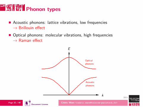
Phonon types
Acoustic phonons: lattice vibrations, low frequencies→ Brillouin effectOptical phonons: molecular vibrations, high frequencies→ Raman effect
k
Acousticphonons
Opticalphonons
E
Page 33 / 40 Cédric Ware <[email protected]>
2011
Document License
Brillouin scattering
Phase matching: kphonon ∝ ωphonon thus, for significant frequencydifference (hence gain), need large kphonon.
⇒ counterpropagating pump (−kp = ks − k ′phonon).
Very narrow bandwidth: few 10 MHz.
⇒ Application: possibly low-bitrate WDM demultiplexing.
→ Mostly, parasitic effect that limits optical power.
Page 34 / 40 Cédric Ware <[email protected]>
2011
Document License
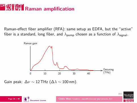
Raman amplification
Raman-effect fiber amplifier (RFA): same setup as EDFA, but the “active”fiber is a standard, long fiber, and λpump chosen as a function of λsignal.
Detuning
Raman gain
(THz)0 10 20 30 40
Gain peak: ∆ν ∼ 12THz (∆λ ∼ 100 nm).
Page 35 / 40 Cédric Ware <[email protected]>
2011
Document License
Pum configuration
Phase matching: kphonon may be large or small compared to kopt forsimilar frequencies, so pumping can be copropagating(kp = ks + kphonon) or counterpropagating (−kp = ks − k ′
phonon)
But: very fast effect ⇒ transfers pump noise to signal
If counterpropagating pump, noise ends up averaged over each bit
⇒ Counterpropagating pump
Page 36 / 40 Cédric Ware <[email protected]>
2011
Document License
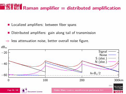
Raman amplifier = distributed amplification
Localized amplifiers: between fiber spans
Distributed amplifiers: gain along tail of transmission
⇒ less attenuation noise, better overall noise figure.
hνBo/2−60
−40
−20
0 100 200 300km
SignalNoise
S (dist.)N (dist.)
dBm
Page 37 / 40 Cédric Ware <[email protected]>
2011
Document License
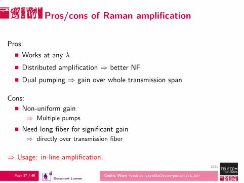
Pros/cons of Raman amplification
Pros:Works at any λDistributed amplification ⇒ better NFDual pumping ⇒ gain over whole transmission span
Cons:Non-uniform gain⇒ Multiple pumps
Need long fiber for significant gain⇒ directly over transmission fiber
⇒ Usage: in-line amplification.
Page 38 / 40 Cédric Ware <[email protected]>
2011
Document License
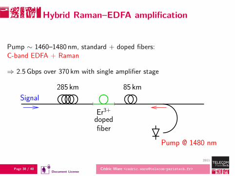
Hybrid Raman–EDFA amplification
Pump ∼ 1460–1480 nm, standard + doped fibers:C-band EDFA + Raman
⇒ 2.5 Gbps over 370 km with single amplifier stage
Pump @ 1480 nm
Signal
Er3+dopedfiber
285 km 85 km
Page 39 / 40 Cédric Ware <[email protected]>
2011
Document License
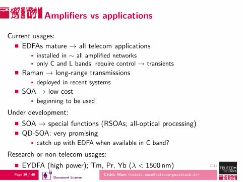
Amplifiers vs applications
Current usages:EDFAs mature → all telecom applications
installed in ∼ all amplified networksonly C and L bands; require control → transients
Raman → long-range transmissionsdeployed in recent systems
SOA → low costbeginning to be used
Under development:SOA → special functions (RSOAs; all-optical processing)QD-SOA: very promising
catch up with EDFA when available in C band?
Research or non-telecom usages:EYDFA (high power); Tm, Pr, Yb (λ < 1500 nm)
Page 40 / 40 Cédric Ware <[email protected]>
2011
Document License
References, further reading
E. Desurvire, “Erbium-Doped Fiber Amplifiers, Device and System Developments”,Wiley-Interscience, 2002.
D. Menashe, “Optical Amplifiers for Modern Networks”, ICTON 2006.
L. Spiekman, “Semiconductor optical amplifiers for reconfigurable optical networks”, J.Optical Networking 6 (11), Nov 2007.
T. Akiyama et al., “Quantum-Dot Semiconductor Optical Amplifiers”, Proc. IEEE 95 (9),Sept 2007.
C. Headley, G. P. Agrawal, “Raman amplification in fiber optical communicationsystems”, Elsevier Academic Press, 2005.
S. Jiang et al., “Full characterization of modern transmission fibers for Ramanamplified-based communication systems”, Optics Express 15 (8), Apr 2007.

Page 41 / 40 Cédric Ware <[email protected]>
2011
Document License
Document License
Academic context } without modification
By downloading or viewing this document, the user accepts and wholly abides by its license, which is set out in the following dispositions.
The licence confers to the user a right to use the consulted or downloaded document, totally or in part, in accordance with the conditions set outhereinafter for non-commercial use only.The right of use set out by the licence allows use in an academic context by a user giving classes in a secondary or higher education establishment andexpressly excludes commercial training and in-work vocational training in particular. This right includes:
the right to copy all or a part of the document onto a computer or paper medium,
the right to distribute all or a part of the document to pupils or students.
No modification of the documents to its contents, form or presentation is allowed. The information relating to the document source and/or its authormust be fully preserved.The right of use set out in the licence is personal, non-exclusive and non-transferable. Any use except that set out in the licence is subject to the prior,express authorisation of the author. [email protected]


![ACROPOLIS RALLY [ERC PROGRAMME 2014]](https://static.fdocument.org/doc/165x107/568c49ce1a28ab4916959c2d/acropolis-rally-erc-programme-2014.jpg)


![ACROPOLIS RALLY [ERC PROGRAMME 2015]](https://static.fdocument.org/doc/165x107/57906fa31a28ab687499c209/acropolis-rally-erc-programme-2015.jpg)