Operational Aspects of the SPEAR 3 Accelerator J. Corbett August 7 ...
72
Operational Aspects of the SPEAR 3 Accelerator J. Corbett August 7, 2003
Transcript of Operational Aspects of the SPEAR 3 Accelerator J. Corbett August 7 ...
Operational Aspectsof the
SPEAR 3 Accelerator
J. CorbettAugust 7, 2003
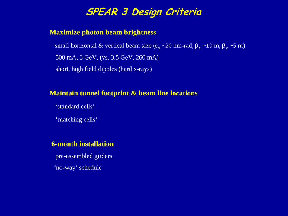
SPEAR 3 Design Criteria
Maximize photon beam brightness
small horizontal & vertical beam size (εx ~20 nm-rad, βx ~10 m, βy ~5 m)
500 mA, 3 GeV, (vs. 3.5 GeV, 260 mA)
short, high field dipoles (hard x-rays)
Maintain tunnel footprint & beam line locations
‘standard cells’
‘matching cells’
6-month installationpre-assembled girders
‘no-way’ schedule
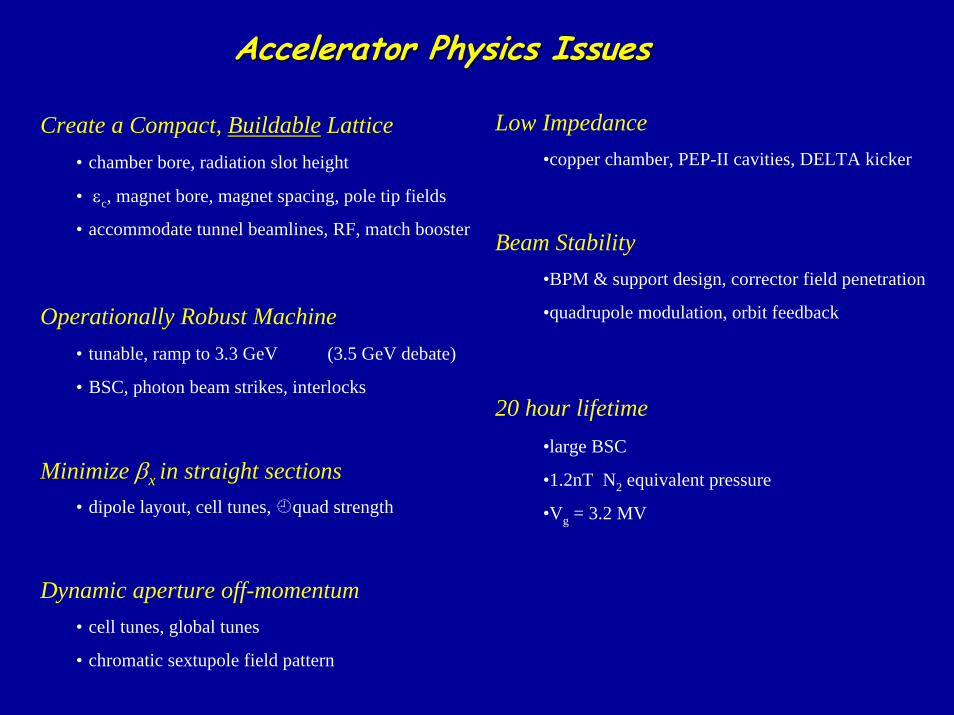
Accelerator Physics IssuesAccelerator Physics Issues
Low Impedance•copper chamber, PEP-II cavities, DELTA kicker
Beam Stability•BPM & support design, corrector field penetration
•quadrupole modulation, orbit feedback
20 hour lifetime•large BSC
•1.2nT N2 equivalent pressure
•Vg = 3.2 MV
Create a Compact, Buildable Lattice• chamber bore, radiation slot height
• εc, magnet bore, magnet spacing, pole tip fields
• accommodate tunnel beamlines, RF, match booster
Operationally Robust Machine• tunable, ramp to 3.3 GeV (3.5 GeV debate)
• BSC, photon beam strikes, interlocks
Minimize βx in straight sections• dipole layout, cell tunes, quad strength
Dynamic aperture off-momentum• cell tunes, global tunes
• chromatic sextupole field pattern
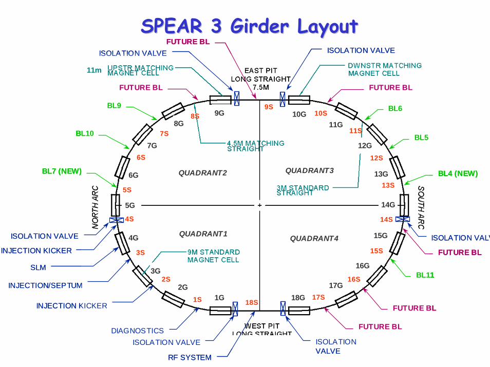
INJECTION KICKER
11m
ISOLATION VALVE ISOLATION VALVE
ISOLATION VALV
ISOLATION VALVEISOLATION VALVEFUTURE BL
FUTURE BL
17S
16S
15S
14S
13S
12S
11S
10S
1S
5S
3S
6S
7S
G9
FUTURE BL
FUTURE BL
BL11
FUTURE BL
BL4 (NEW)
BL5
BL6
DIAGNOSTICS
BL9
BL10
BL7 (NEW)
INJECTION/SEPTUM
INJECTION KICKER
SLM
RF SYSTEM
ISOLATION VALVE
1G2G
9S
18S
3G
4G
5G
6G
7G
8G9G 10G
11G
12G
13G
14G
15G
16G
17G18G
QUADRANT1
QUADRANT2 QUADRANT3
QUADRANT4
2S
4S
FUTURE BL
8S
INJECTION KICKER
11m
ISOLATION VALVE ISOLATION VALVE
ISOLATION VALV
ISOLATION VALVEISOLATION VALVEFUTURE BL
FUTURE BL
17S
16S
15S
14S
13S
12S
11S
10S
1S
5S
3S
6S
7S
G9
FUTURE BL
FUTURE BL
BL11
FUTURE BL
BL4 (NEW)
BL5
BL6
DIAGNOSTICS
BL9
BL10
BL7 (NEW)
INJECTION/SEPTUM
INJECTION KICKER
SLM
RF SYSTEM
ISOLATION VALVE
1G2G
9S
18S
3G
4G
5G
6G
7G
8G9G 10G
11G
12G
13G
14G
15G
16G
17G18G
QUADRANT1
QUADRANT2 QUADRANT3
QUADRANT4
2S
4S
FUTURE BL
8S
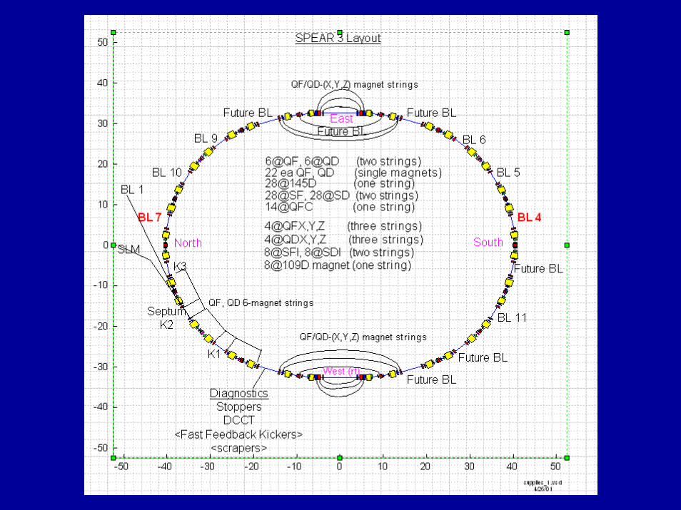
SPEAR 3 Girder LayoutSPEAR 3 Girder Layout
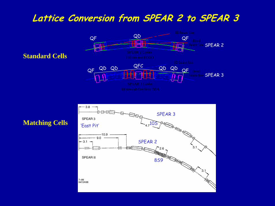
Lattice Conversion from SPEAR 2 to SPEAR 3
SPEAR 2 Girder160 nm-rad FODO
SPEAR 3 Girder18 nm-rad Gradient DBA
ID beam line
ID beam line
Bendbeam line
Bendbeam line
QDQFCQFQF QD QDQD
QF QFQD
SPEAR 2
SPEAR 3
Standard Cells
SPEAR 3
SPEAR 2
‘East Pit’
8S9
10SMatching Cells
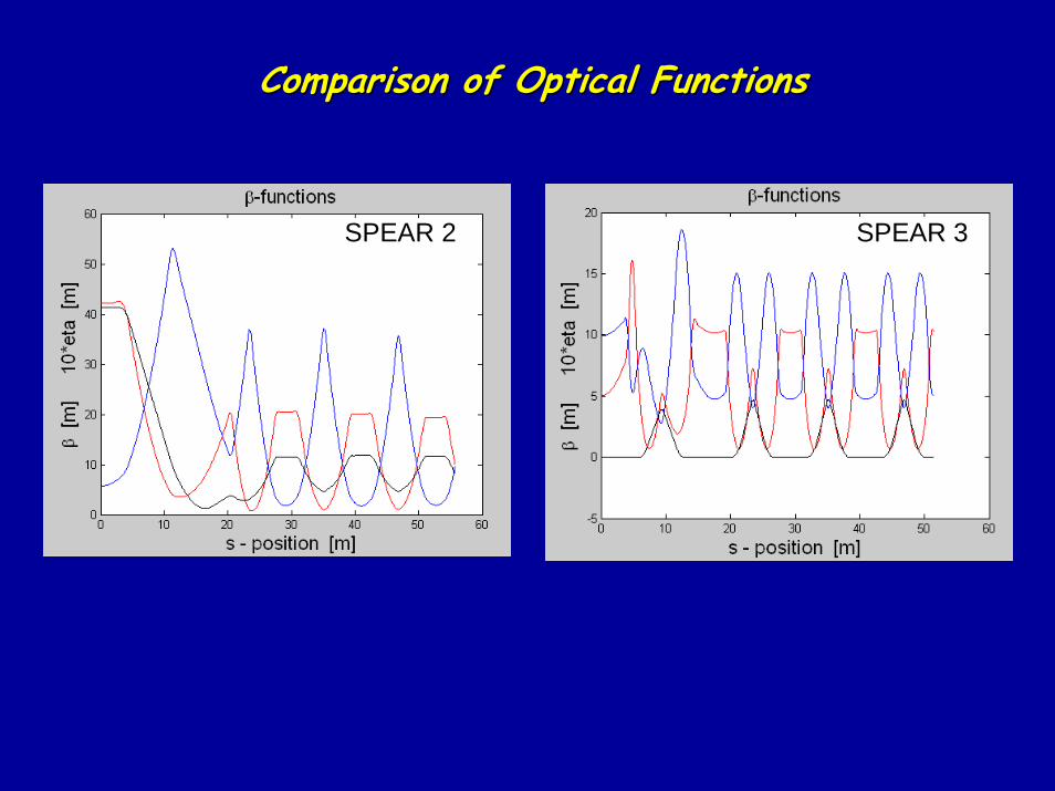
Comparison of Optical FunctionsComparison of Optical Functions
SPEAR 2 SPEAR 3
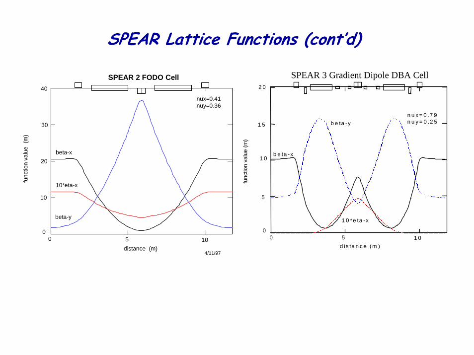
SPEAR Lattice Functions (cont’d)
0 5 1 0d is ta n c e (m )
0
5
1 0
1 5
2 0
n u x = 0 .7 9n u y = 0 .2 5
b e ta -x
b e ta -y
1 0 *e ta -x
func
tion
valu
e (m
)
SPEAR 3 Gradient Dipole DBA Cell
10
20
05 100
distance (m)
beta-x
beta-y
10*eta-x
SPEAR 2 FODO Cell
4/11/97
nux=0.41nuy=0.36
func
tion
valu
e (m
)
30
40
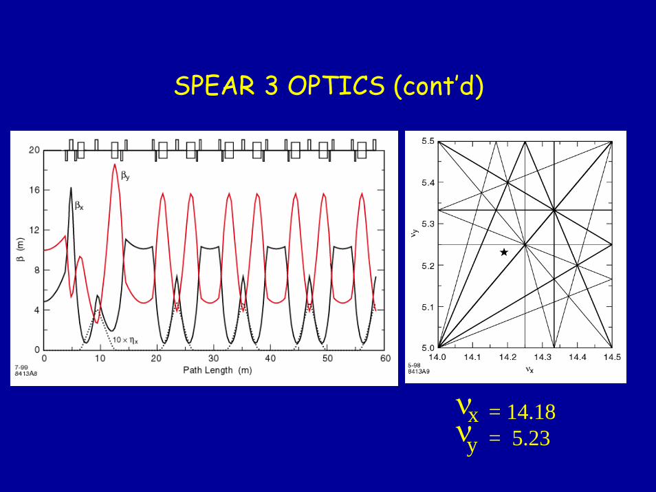
SPEAR 3 OPTICS (cont’d)
= 14.18= 5.23
νxyν
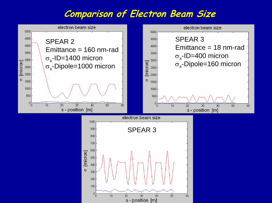
Comparison of Electron Beam SizeComparison of Electron Beam Size
SPEAR 3 Emittance = 18 nm-radσx-ID=400 micronσx-Dipole=160 micron
SPEAR 2 Emittance = 160 nm-radσx-ID=1400 micronσx-Dipole=1000 micron
SPEAR 3
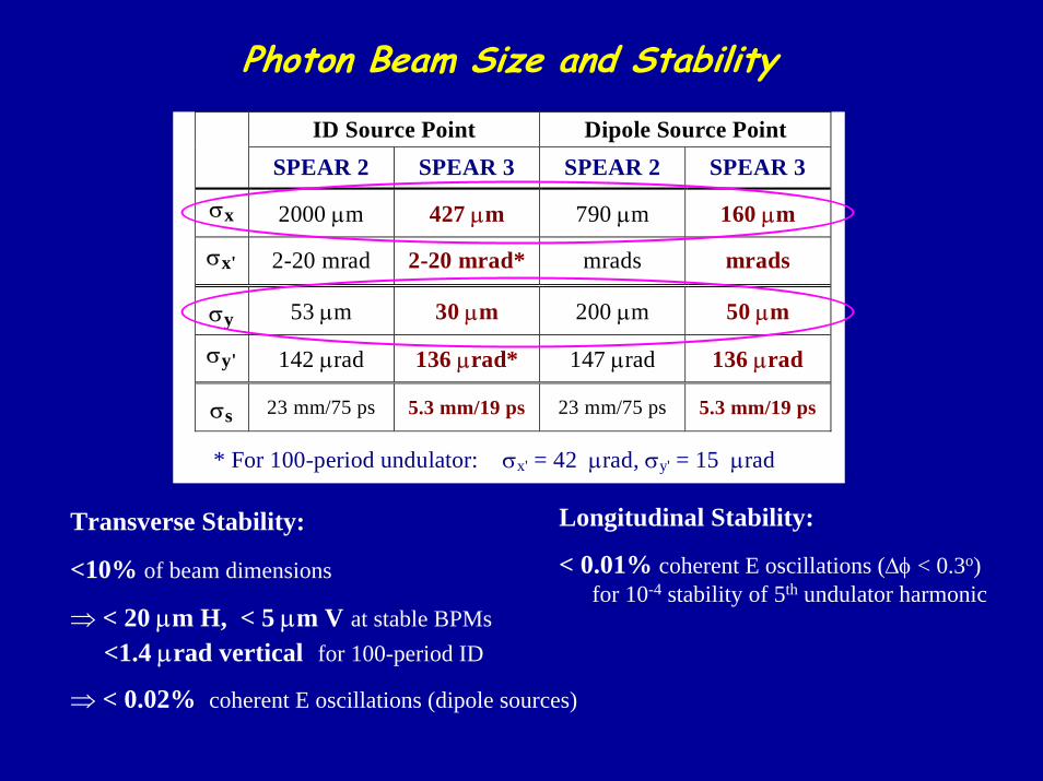
Photon Beam Size and Stability
ID Source Point Dipole Source PointSPEAR 2 SPEAR 3 SPEAR 2 SPEAR 3
σx 2000 µm 427 µm 790 µm 160 µm
σx' 2-20 mrad 2-20 mrad* mrads mrads
σy 53 µm 30 µm 200 µm 50 µm
σy' 142 µrad 136 µrad* 147 µrad 136 µrad
σs 23 mm/75 ps 5.3 mm/19 ps 23 mm/75 ps 5.3 mm/19 ps
* For 100-period undulator: σx' = 42 µrad, σy' = 15 µrad
Transverse Stability:
<10% of beam dimensions
⇒ < 20 µm H, < 5 µm V at stable BPMs<1.4 µrad vertical for 100-period ID
⇒ < 0.02% coherent E oscillations (dipole sources)
Longitudinal Stability:
< 0.01% coherent E oscillations (∆φ < 0.3o)for 10-4 stability of 5th undulator harmonic
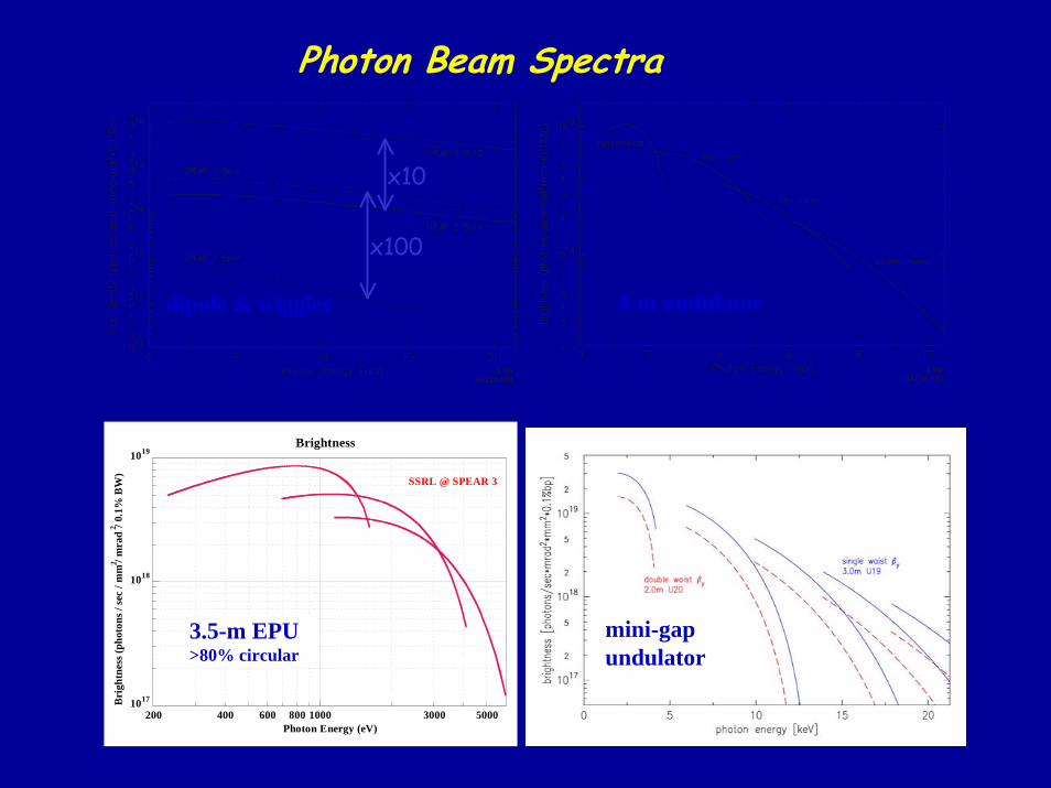
Photon Beam Spectra
8-998413A300
4-m undulator
8-998413A299
dipole & wiggler
1017
1018
1019
200 400 600 800 1000 3000 5000
Bri
ghtn
ess (
phot
ons /
sec
/ mm
2 / m
rad
2 / 0.
1% B
W)
Photon Energy (eV)
SSRL @ SPEAR 3
Brightness
3.5-m EPU>80% circular
mini-gapundulator
x100
x10
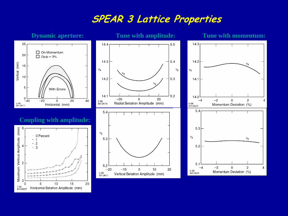
SPEAR 3 Lattice PropertiesDynamic aperture: Tune with amplitude: Tune with momentum:
Coupling with amplitude:
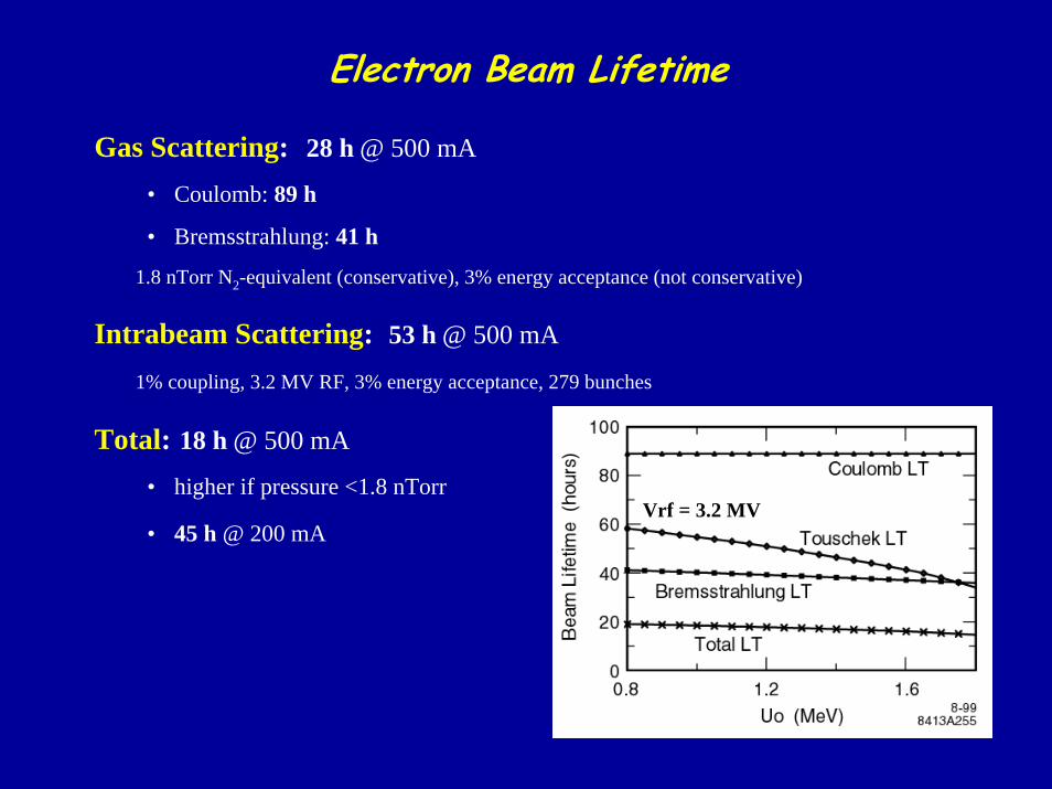
Electron Beam Lifetime
Gas Scattering: 28 h @ 500 mA
• Coulomb: 89 h
• Bremsstrahlung: 41 h
1.8 nTorr N2-equivalent (conservative), 3% energy acceptance (not conservative)
Intrabeam Scattering: 53 h @ 500 mA
1% coupling, 3.2 MV RF, 3% energy acceptance, 279 bunches
Total: 18 h @ 500 mA
• higher if pressure <1.8 nTorr
• 45 h @ 200 mAVrf = 3.2 MV
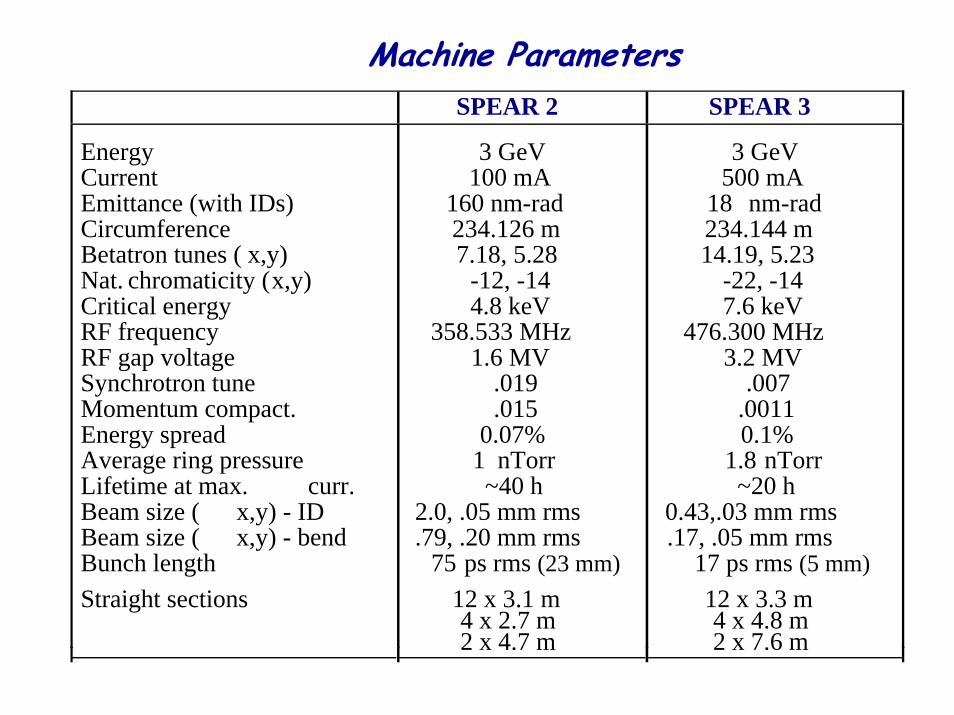
Machine ParametersSPEAR 2 SPEAR 3
EnergyCurrentEmittance (with IDs)CircumferenceBetatron tunes ( x,y)Nat. chromaticity (x,y)Critical energyRF frequencyRF gap voltageSynchrotron tuneMomentum compact.Energy spreadAverage ring pressureLifetime at max. curr.Beam size ( x,y) - IDBeam size ( x,y) - bendBunch lengthStraight sections
3 GeV100 mA
160 nm-rad234.126 m7.18, 5.28
-12, -144.8 keV
358.533 MHz1.6 MV
.019
.0150.07%
1 nTorr~40 h
2.0, .05 mm rms.79, .20 mm rms
75 ps rms (23 mm)12 x 3.1 m4 x 2.7 m2 x 4.7 m
3 GeV500 mA
18 nm-rad234.144 m14.19, 5.23
-22, -147.6 keV
476.300 MHz3.2 MV
.007.00110.1%
1.8 nTorr~20 h
0.43,.03 mm rms.17, .05 mm rms
17 ps rms (5 mm)12 x 3.3 m4 x 4.8 m2 x 7.6 m
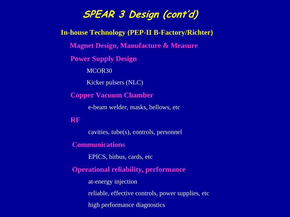
SPEAR 3 Design (cont’d)In-house Technology (PEP-II B-Factory/Richter)
Magnet Design, Manufacture & Measure
Power Supply DesignMCOR30
Kicker pulsers (NLC)
Copper Vacuum Chambere-beam welder, masks, bellows, etc
RFcavities, tube(s), controls, personnel
CommunicationsEPICS, bitbus, cards, etc
Operational reliability, performanceat-energy injection
reliable, effective controls, power supplies, etc
high performance diagnostics
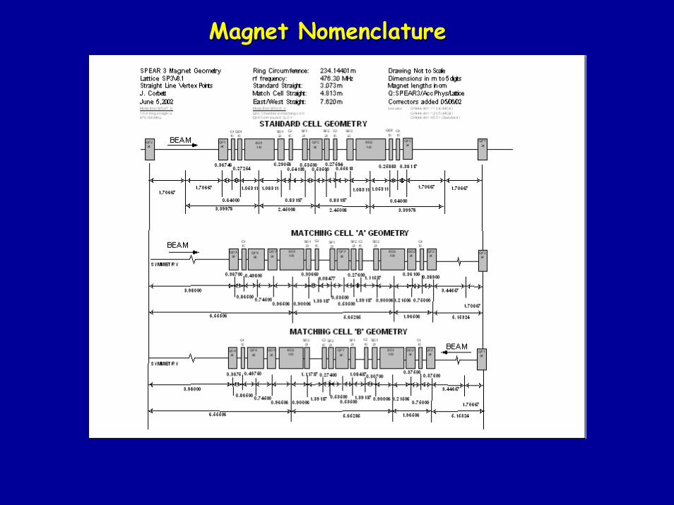
Magnet NomenclatureMagnet Nomenclature
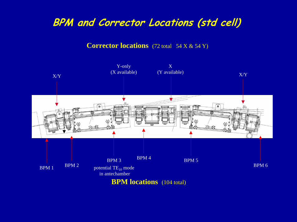
BPM and Corrector Locations (std cell)
Corrector locations (72 total 54 X & 54 Y)
Y-only(X available)
X(Y available) X/YX/Y
BPM 4BPM 3 BPM 5BPM 2 BPM 6BPM 1 potential TE10 mode
in antechamber
BPM locations (104 total)
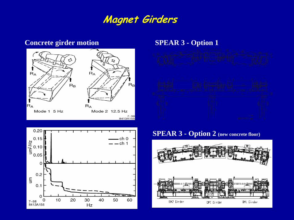
Magnet Girders
Concrete girder motion SPEAR 3 - Option 1
8/998413A293.eps
SPEAR 3 - Option 2 (new concrete floor)
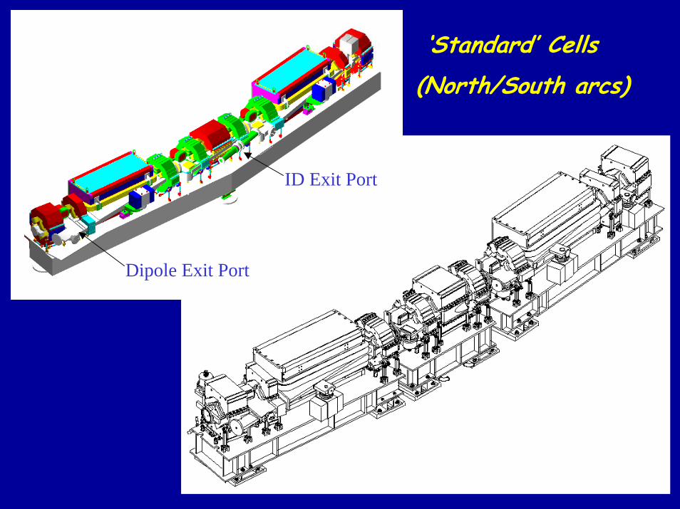
‘Standard’ Cells(North/South arcs)
ID Exit Port
Dipole Exit Port
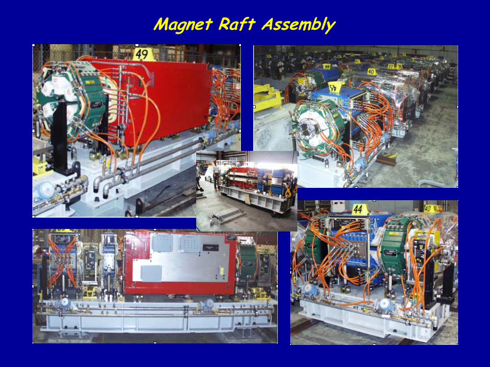
Magnet Raft Assembly
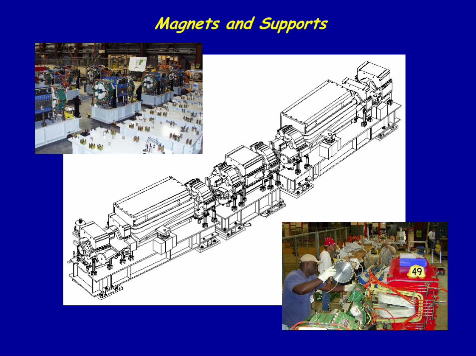
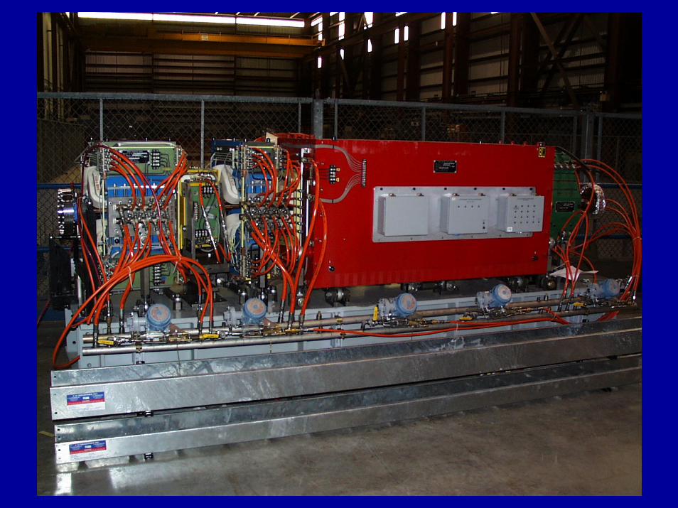
Magnets and Supports
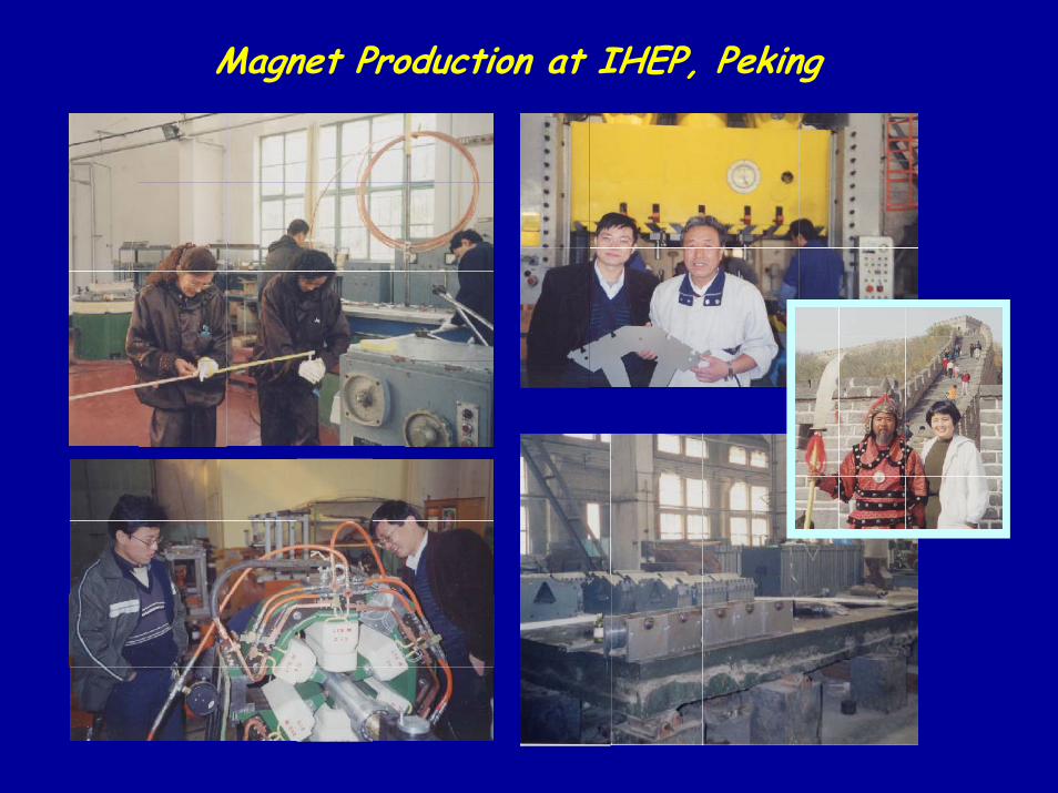
Magnet Production at IHEP, Peking
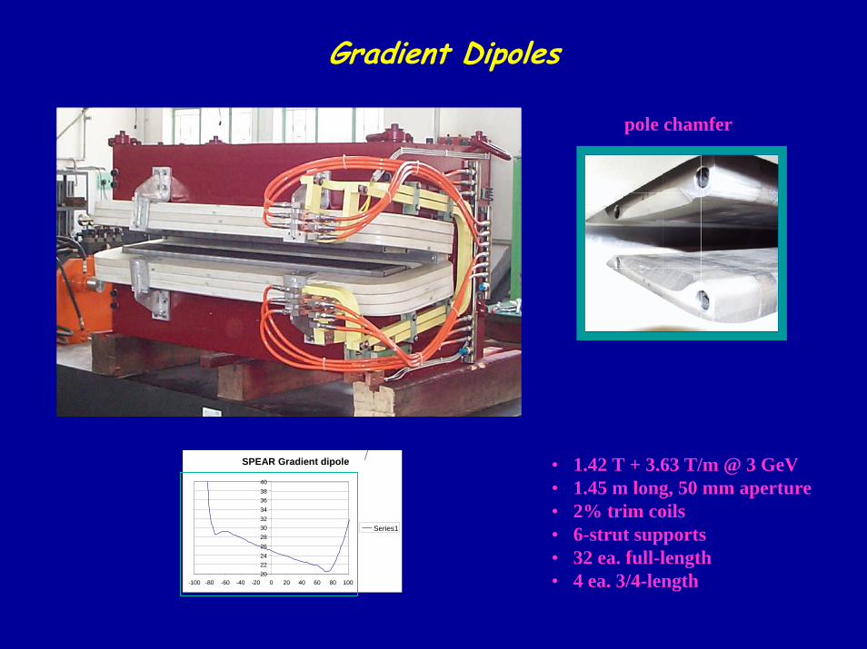
Gradient Dipoles
pole chamfer
SPEAR Gradient dipole
2022242628303234363840
-100 -80 -60 -40 -20 0 20 40 60 80 100
Series1
• 1.42 T + 3.63 T/m @ 3 GeV• 1.45 m long, 50 mm aperture• 2% trim coils• 6-strut supports• 32 ea. full-length• 4 ea. 3/4-length
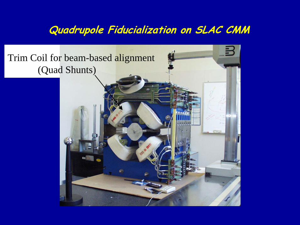
Quadrupole Fiducialization on SLAC CMM
Trim Coil for beam-based alignment(Quad Shunts)
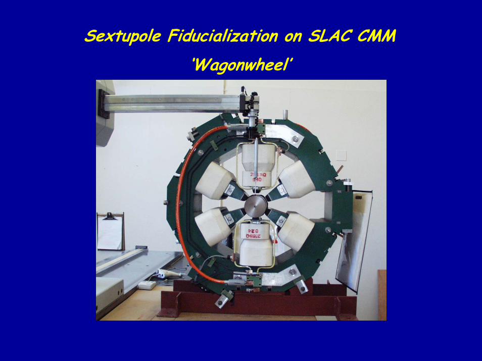
Sextupole Fiducialization on SLAC CMM‘Wagonwheel’
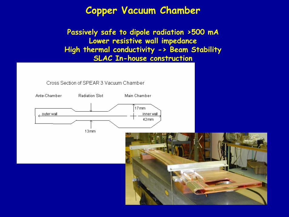
Copper Vacuum Chamber
Passively safe to dipole radiation >500 mALower resistive wall impedance
High thermal conductivity -> Beam StabilitySLAC In-house construction
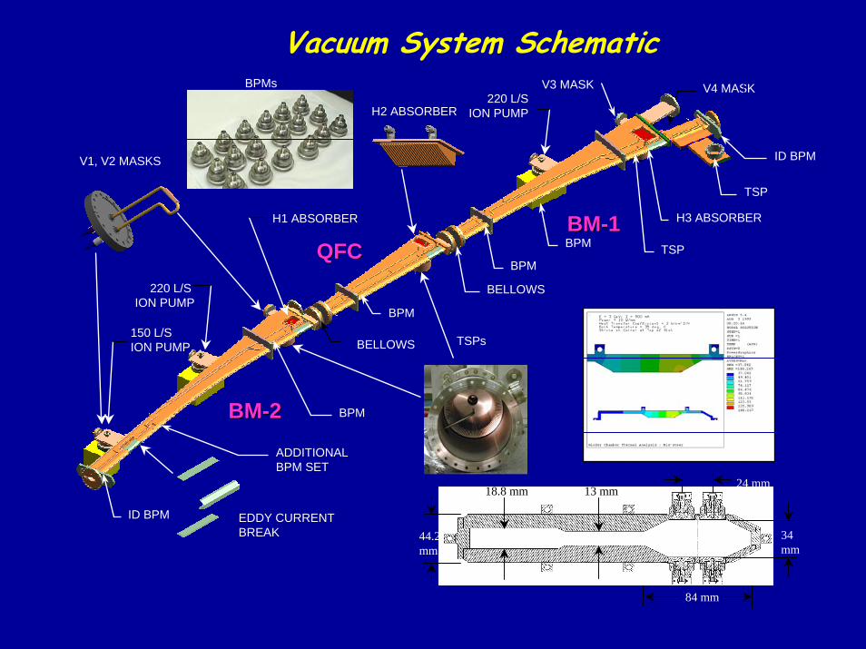
Vacuum System SchematicV4 MASK
V1, V2 MASKS
BPMs
H2 ABSORBER
TSPs
EDDY CURRENTBREAK
BMBM--22
QFCQFCBMBM--11
220 L/SION PUMP
150 L/S ION PUMP
TSP
V3 MASK
BELLOWS
BELLOWS
H1 ABSORBER H3 ABSORBER
TSP
BPM
BPM
BPM
ID BPM
ADDITIONAL BPM SET
220 L/S ION PUMP
84 mm
44.2mm
34 mm
24 mm13 mm18.8 mm
ID BPM
BPM
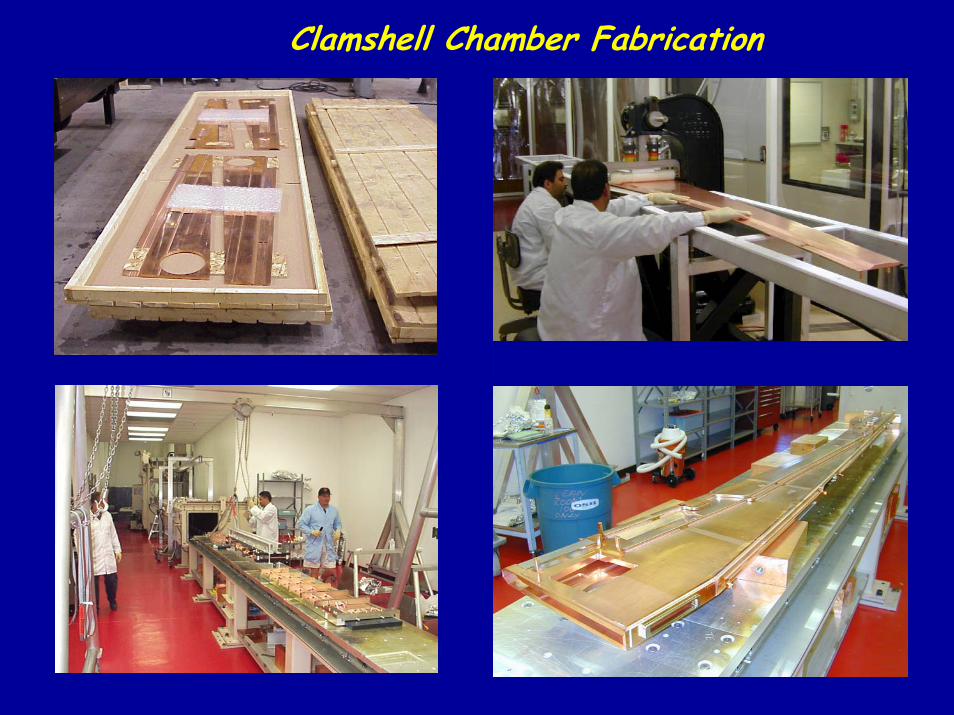
Clamshell Chamber Fabrication
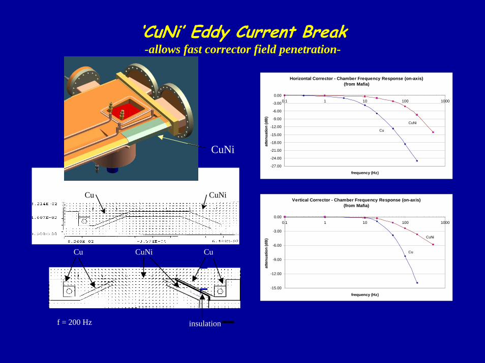
‘CuNi’ Eddy Current Break-allows fast corrector field penetration-
CuNiCu
Cu CuNi Cu
insulationf = 200 Hz
Horizontal Corrector - Chamber Frequency Response (on-axis)(from Mafia)
-27.00
-24.00
-21.00
-18.00
-15.00
-12.00
-9.00
-6.00
-3.00
0.000.1 1 10 100 1000
frequency (Hz)
atte
nuat
ion
(dB
)
Cu
CuNi
Vertical Corrector - Chamber Frequency Response (on-axis)(from Mafia)
-15.00
-12.00
-9.00
-6.00
-3.00
0.000.1 1 10 100 1000
frequency (Hz)
atte
nuat
ion
(dB
)
Cu
CuNi
CuNi
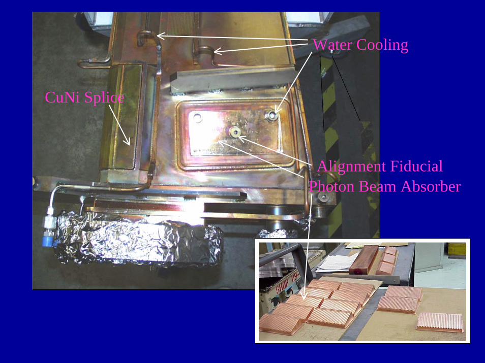
Photon Beam Absorber
CuNi Splice
Water Cooling
Alignment Fiducial
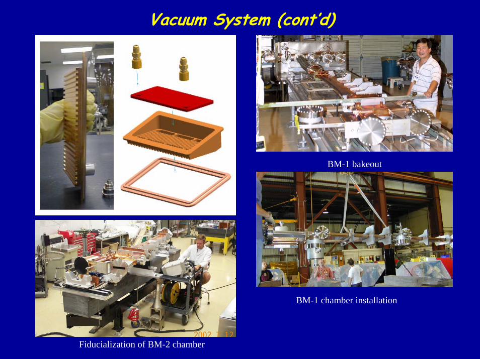
Vacuum System (cont’d)
BM-1 bakeout
BM-1 chamber installation
Fiducialization of BM-2 chamber
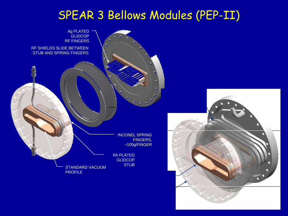
SPEAR 3 Bellows Modules (PEP-II)
STANDARD VACUUM PROFILE
Ag PLATED GLIDCOP
RF FINGERS
INCONEL SPRING FINGERS,
~100g/FINGER
Rh PLATED GLIDCOP
STUB
RF SHIELDS SLIDE BETWEEN STUB AND SPRING FINGERS
COOLING FORDIPOLE VERTICAL
MISTEER, ~ 3KW
STANDARD VACUUM PROFILE
BL11 TRANS/BEL, ONLYADDITIONAL 1.96”
LONGER THANSTANDARD BELLOWS
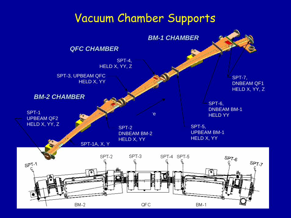
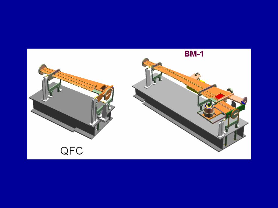
BMBM--2 CHAMBER2 CHAMBER
QFC CHAMBERQFC CHAMBERBMBM--1 CHAMBER1 CHAMBER
SPT-5, UPBEAM BM-1HELD X, YY
SPT-3, UPBEAM QFCHELD X, YY
-eSPT-1 UPBEAM QF2HELD X, YY, Z
SPT-2 DNBEAM BM-2HELD X, YY
SPT-4,HELD X, YY, Z
SPT-7, DNBEAM QF1HELD X, YY, Z
SPT-6, DNBEAM BM-1HELD YY
Vacuum Chamber Supports
SPT-1A, X, Y
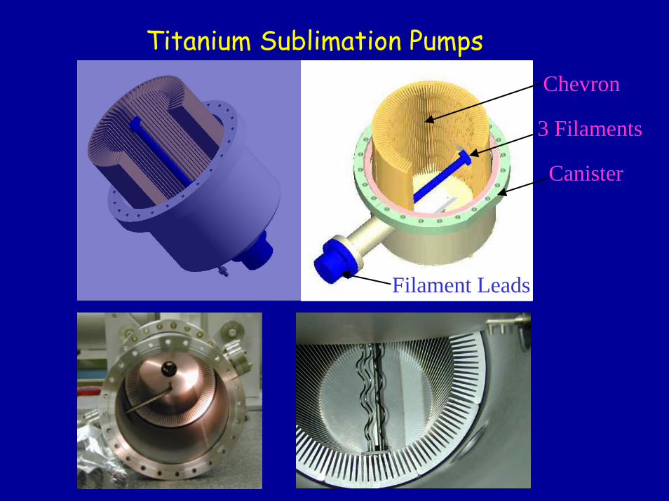
Titanium Sublimation Pumps
Canister
Chevron
3 Filaments
Filament Leads
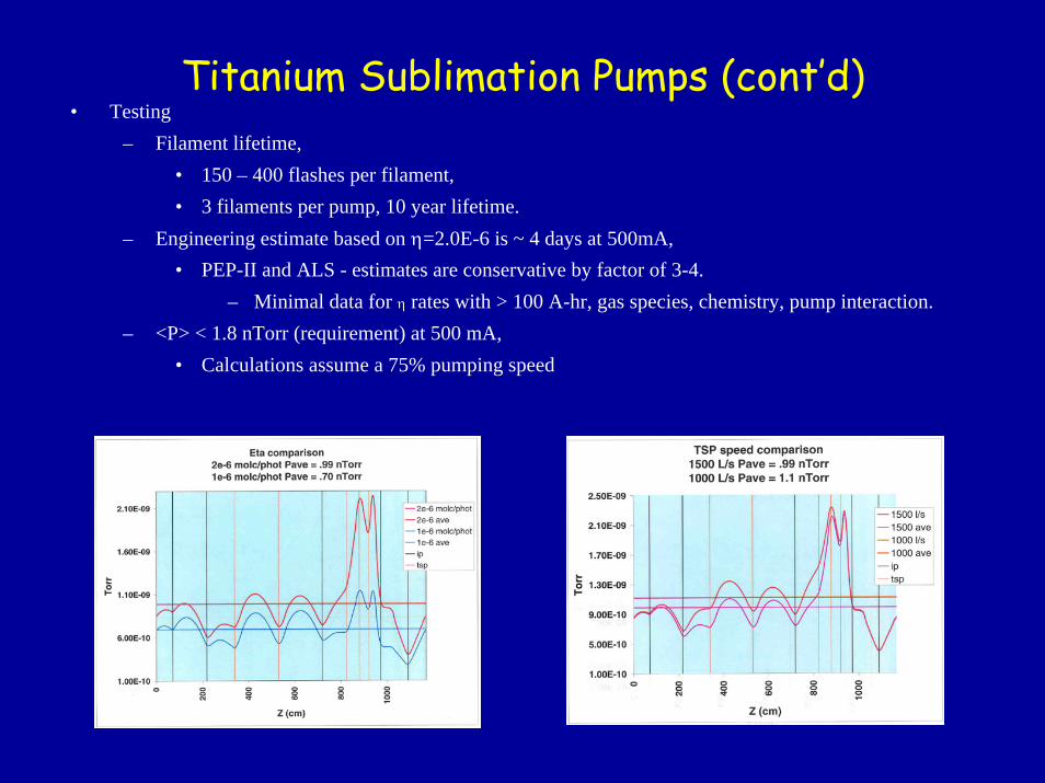
Titanium Sublimation Pumps (cont’d)• Testing
– Filament lifetime, • 150 – 400 flashes per filament,• 3 filaments per pump, 10 year lifetime.
– Engineering estimate based on η=2.0E-6 is ~ 4 days at 500mA,• PEP-II and ALS - estimates are conservative by factor of 3-4.
– Minimal data for η rates with > 100 A-hr, gas species, chemistry, pump interaction.– <P> < 1.8 nTorr (requirement) at 500 mA,
• Calculations assume a 75% pumping speed
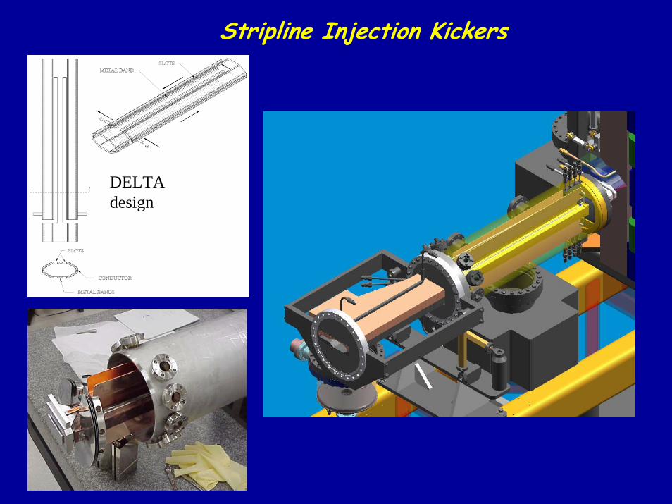
Stripline Injection Kickers
DELTA design
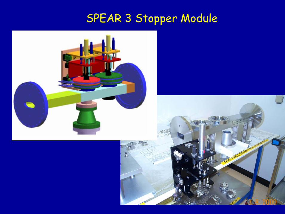
SPEAR 3 Stopper Module
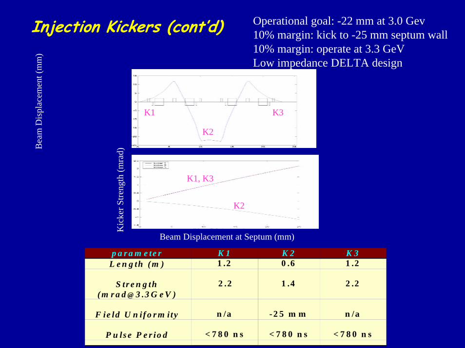
Injection Kickers (cont’d) Operational goal: -22 mm at 3.0 Gev10% margin: kick to -25 mm septum wall10% margin: operate at 3.3 GeVLow impedance DELTA design
Bea
m D
ispl
acem
ent (
mm
)
K3K1
K2K
icke
r Stre
ngth
(mra
d)
K1, K3
K2
Beam Displacement at Septum (mm)
p a r a m e te r K 1 K 2 K 3L e n g th (m ) 1 .2 0 .6 1 .2
S tr e n g th( m r a d @ 3 .3 G e V )
2 .2 1 .4 2 .2
F ie ld U n if o r m ity n /a -2 5 m m n /a
P u ls e P e r io d < 7 8 0 n s < 7 8 0 n s < 7 8 0 n s
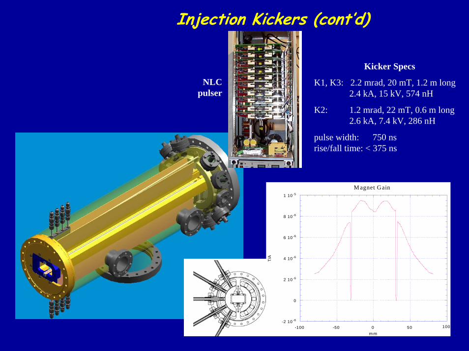
Injection Kickers (cont’d)
Kicker Specs
K1, K3: 2.2 mrad, 20 mT, 1.2 m long2.4 kA, 15 kV, 574 nH
K2: 1.2 mrad, 22 mT, 0.6 m long2.6 kA, 7.4 kV, 286 nH
pulse width: 750 ns rise/fall time: < 375 ns
-2 10 -6
0
2 10 -6
4 10 -6
6 10 -6
8 10 -6
1 10 -5
-100 -50 0 50 100
T/A
M agnet Gain
mm
NLCpulser
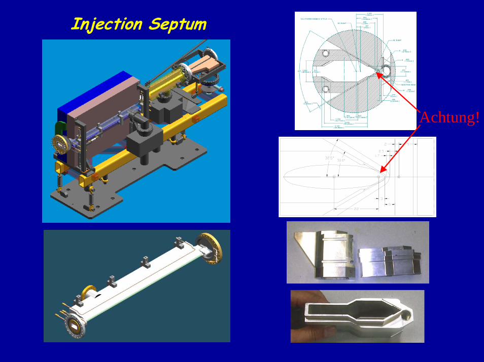
Injection Septum
Achtung!
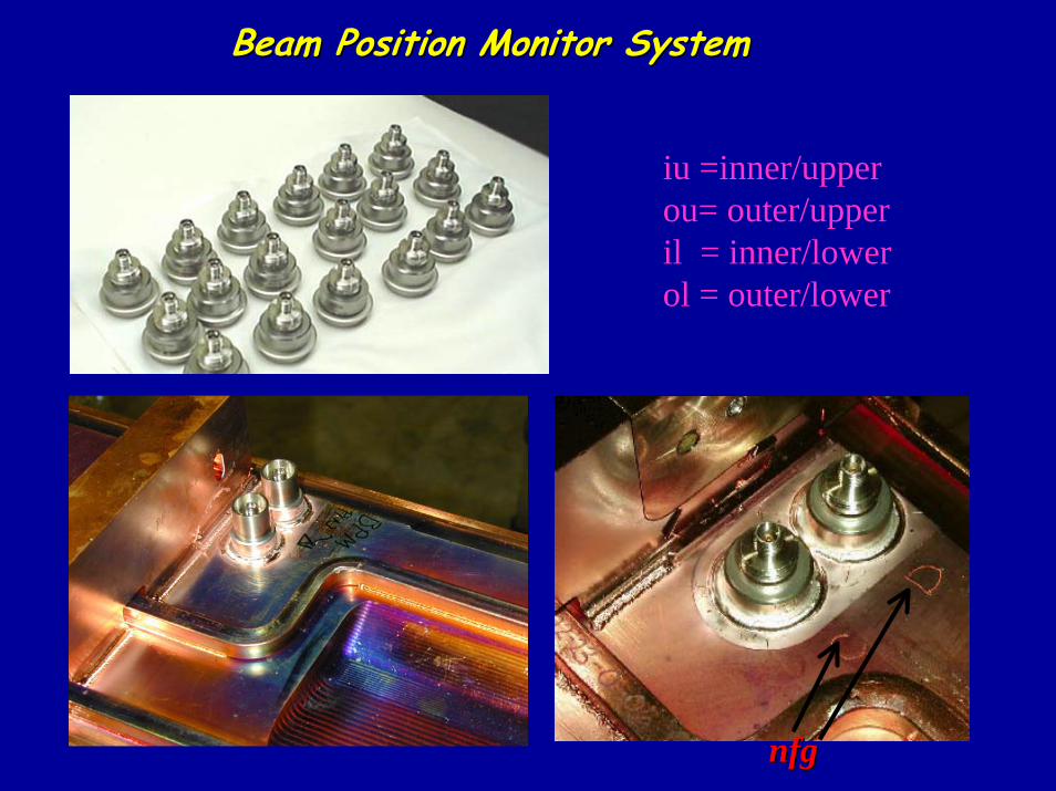
Beam Position Monitor SystemBeam Position Monitor System
iu =inner/upperou= outer/upperil = inner/lowerol = outer/lower
nfgnfg
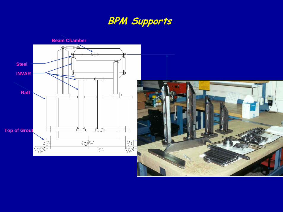
BPM Supports
Steel
INVAR
Top of Grout
∆Y = 2.57 µm (FIXED)∆Y = 3.19 µm (FLEX
Raft
Beam Chamber
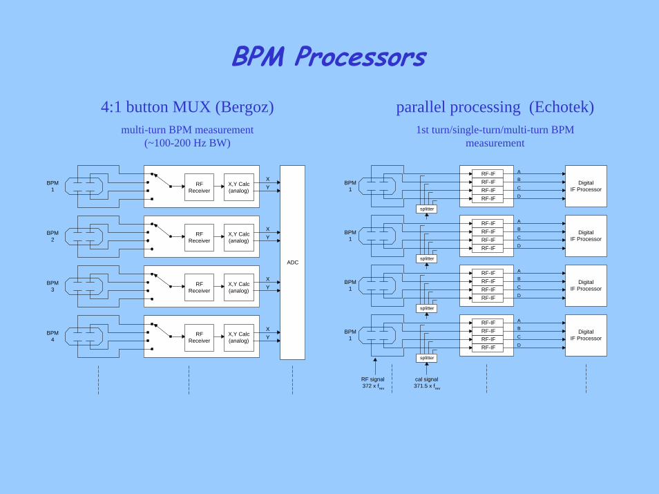
BPM Processors4:1 button MUX (Bergoz)
multi-turn BPM measurement(~100-200 Hz BW)
parallel processing (Echotek)1st turn/single-turn/multi-turn BPM
measurement
ADC
BPM1
BPM2
BPM4
BPM3
RFReceiver
X,Y Calc(analog)
XY
RFReceiver
X,Y Calc(analog)
XY
RFReceiver
X,Y Calc(analog)
XY
RFReceiver
X,Y Calc(analog)
XY
cal signal371.5 x frev
RF signal372 x frev
BPM1
RF-IF
RF-IF RF-IF RF-IF Digital
IF Processor
splitter
A
B
C
D
BPM1
RF-IF
RF-IF RF-IF RF-IF Digital
IF Processor
splitter
A
B
C
D
BPM1
RF-IF
RF-IF RF-IF RF-IF Digital
IF Processor
splitter
A
B
C
D
BPM1
RF-IF
RF-IF RF-IF RF-IF Digital
IF Processor
splitter
A
B
C
D
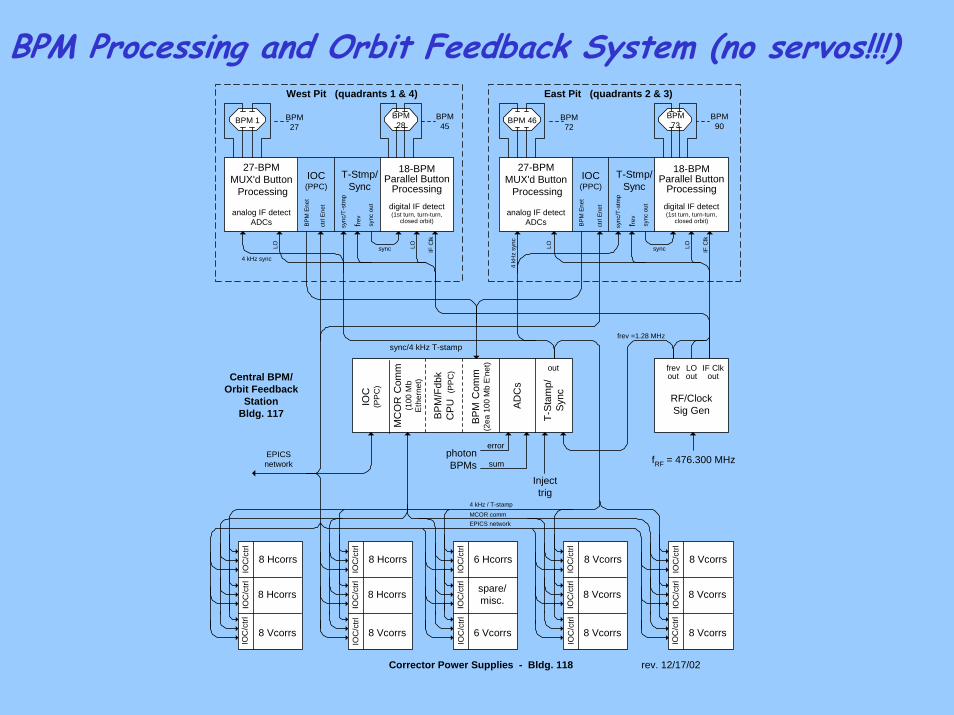
BPM Processing and Orbit Feedback System (no servos!!!)
Corrector Power Supplies - Bldg. 118 rev. 12/17/02
Central BPM/Orbit Feedback
StationBldg. 117
EPICSnetwork
Injecttrig
6 Hcorrs
6 Vcorrs
spare/misc.
IOC
/ctrl
IOC
/ctrl
IOC
/ctrl
IOC
(PP
C)
MC
OR
Com
m(1
00 M
bE
ther
net)
BPM
/Fdb
kC
PU (
PPC
)
T-St
amp/
Sync
out
BPM
Com
m(2
ea 1
00 M
b E
'net
)
West Pit (quadrants 1 & 4) East Pit (quadrants 2 & 3)
8 Hcorrs
8 Vcorrs
8 Hcorrs
IOC
/ctrl
IOC
/ctrl
IOC
/ctrl
8 Hcorrs
8 Vcorrs
8 Hcorrs
IOC
/ctrl
IOC
/ctrl
IOC
/ctrl
8 Vcorrs
8 Vcorrs
8 Vcorrs
IOC
/ctrl
IOC
/ctrl
IOC
/ctrl
8 Vcorrs
8 Vcorrs
8 Vcorrs
IOC
/ctrl
IOC
/ctrl
IOC
/ctrl
frev =1.28 MHzsync/4 kHz T-stamp
BPM72
BPM 46 BPM73
BPM90
BPM27
BPM 1 BPM28
BPM45
4 kHz sync
LO LO IF C
lk
4 kH
z sy
nc
LO LO IF C
lk
4 kHz / T-stampMCOR commEPICS network
fRF = 476.300 MHz
frevout
RF/ClockSig Gen
LOout
IF Clkout
syncsync
27-BPMMUX'd Button Processing
analog IF detectADCs
18-BPMParallel Button
Processing
digital IF detect(1st turn, turn-turn,
closed orbit)
T-Stmp/Sync
IOC(PPC)
ctrl
Enet
BPM
Ene
t
sync
out
frev
syn
c/T-
stm
p
27-BPMMUX'd Button Processing
analog IF detectADCs
18-BPMParallel Button
Processing
digital IF detect(1st turn, turn-turn,
closed orbit)
T-Stmp/Sync
IOC(PPC)
ctrl
Enet
BPM
Ene
t
sync
out
frev
syn
c/T-
stm
p
ADC
s
error
sumphotonBPMs
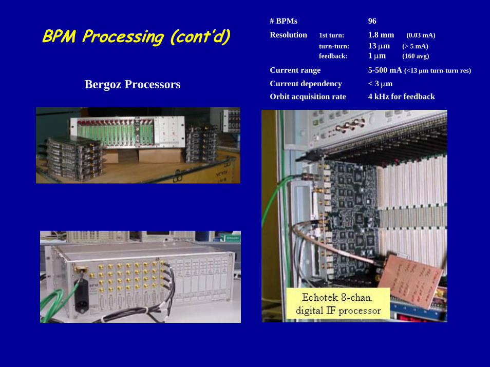
# BPMs 96
Resolution 1st turn: 1.8 mm (0.03 mA)turn-turn: 13 µm (> 5 mA)feedback: 1 µm (160 avg)
Current range 5-500 mA (<13 µm turn-turn res)
Current dependency < 3 µm Orbit acquisition rate 4 kHz for feedback
BPM Processing (cont’d)
Bergoz Processors
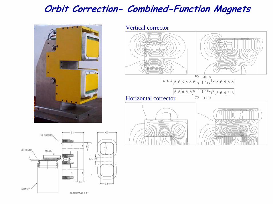
Orbit Correction- Combined-Function Magnets
Vertical corrector
Horizontal corrector
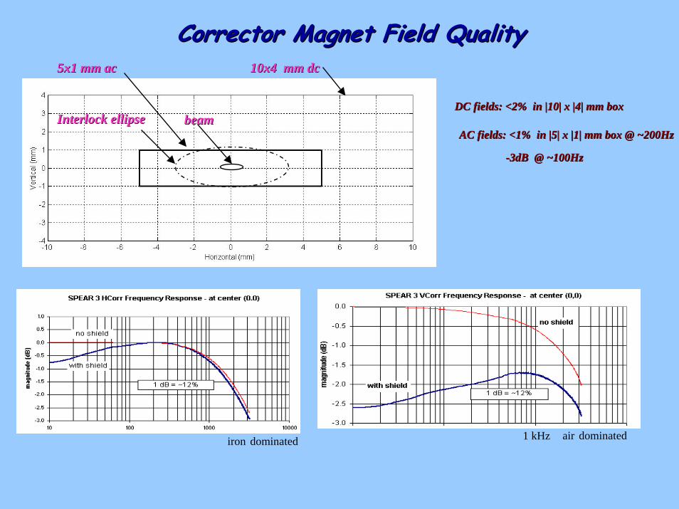
Corrector Magnet Field QualityCorrector Magnet Field Quality5x1 mm ac
air dominatediron dominated
10x4 mm dc10x4 mm dc5x1 mm ac
DC fields: <2% in |10| x |4| mm boxDC fields: <2% in |10| x |4| mm boxbeambeamInterlock ellipseInterlock ellipse
AC fields: <1% in |5| x |1| mm box @ ~200HzAC fields: <1% in |5| x |1| mm box @ ~200Hz
--3dB @ ~100Hz3dB @ ~100Hz
1 kHz
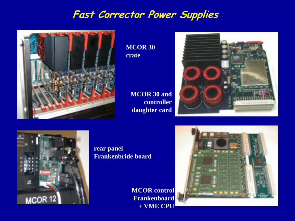
Fast Corrector Power Supplies
MCOR 30crate
MCOR 30 and controller
daughter card
rear panel Frankenbride board
MCOR control Frankenboard
+ VME CPU
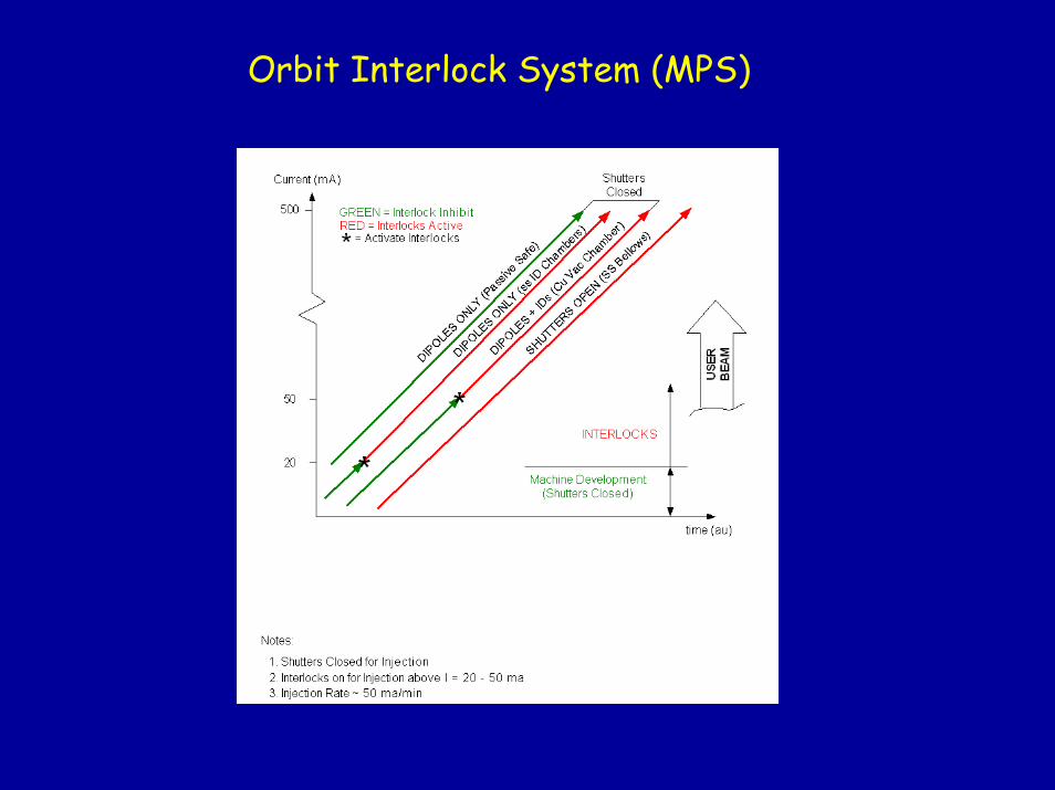
Orbit Interlock System (MPS)
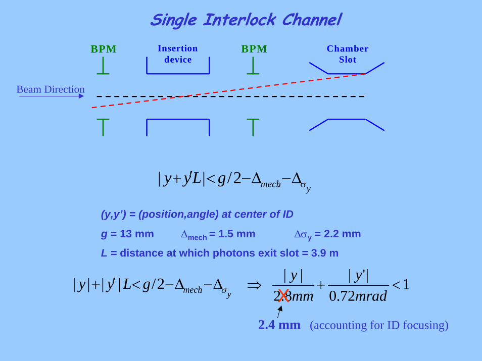
Single Interlock Channel
BPM BPMInsertion device
ChamberSlot
Beam Direction
ymechgLyy σ∆−∆−<′+ .2/ ||
(y,y’) = (position,angle) at center of ID
g = 13 mm ∆mech = 1.5 mm ∆σy = 2.2 mm
L = distance at which photons exit slot = 3.9 m
ymechgLyy σ∆−∆−<′+ .2/ |||| 172.0
|'|8.2
||<+⇒
mrady
mmy
X2.4 mm (accounting for ID focusing)
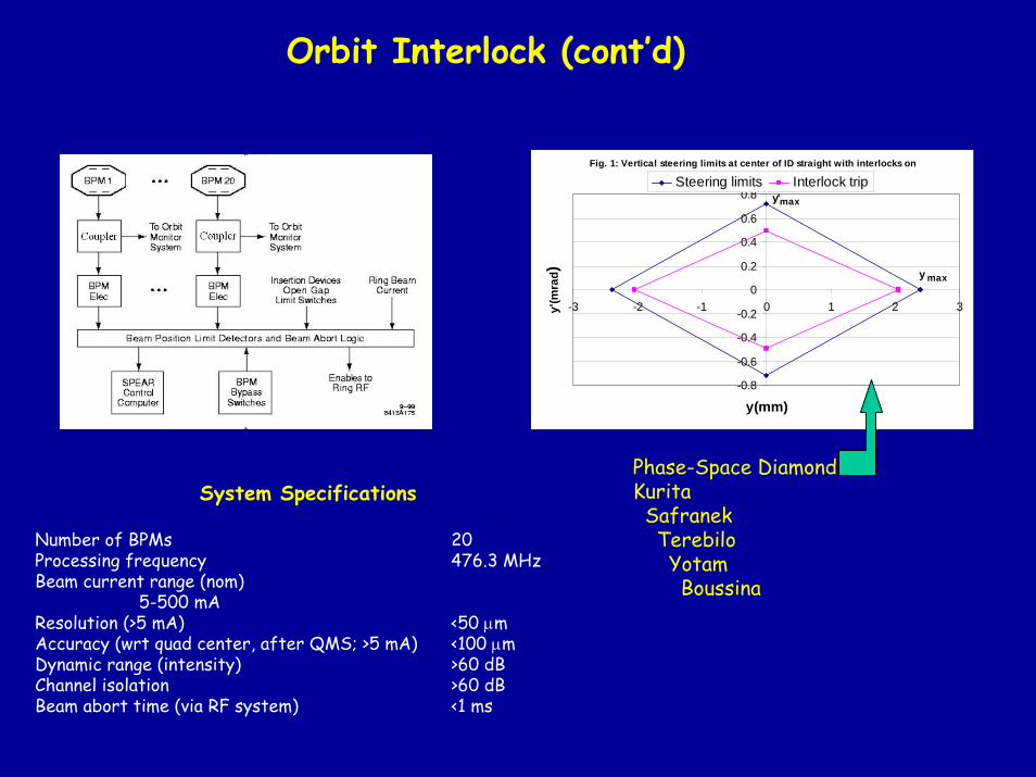
Orbit Interlock (cont’d)
Fig. 1: Vertical steering limits at center of ID straight with interlocks on
-0.8
-0.6
-0.4
-0.2
0
0.2
0.4
0.6
0.8
-3 -2 -1 0 1 2 3
y(mm)
y'(m
rad)
Steering limits Interlock trip
y max
y'max
Phase-Space DiamondKuritaSafranekTerebiloYotamBoussina
System Specifications
Number of BPMs 20Processing frequency 476.3 MHzBeam current range (nom)
5-500 mAResolution (>5 mA) <50 µmAccuracy (wrt quad center, after QMS; >5 mA) <100 µmDynamic range (intensity) >60 dBChannel isolation >60 dBBeam abort time (via RF system) <1 ms
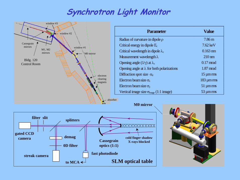
Synchrotron Light Monitor
Parameter Value
Radius of curvature in dipole ρ 7.86 m Critical energy in dipole Ec 7.62 keV Critical wavelength in dipole λc 0.163 nm Measurement wavelength λ 210 nm Opening angle (1/γ) at λc 0.17 mrad Opening angle at λ for both polarizations 1.87 mrad Diffraction spot size σd 15 µm rms Electron beam size σx 183 µm rms Electron beam size σy 51 µm rms Vertical image size σimage (1:1 image) 53 µm rms
M0 mirror
Cassegrain optics (1:1)0D filter
slit
demag
filter
streak camera
gated CCD camera
SLM optical table
cold finger shadowX-rays blocked
fast photodiode
to MCA
splitters
M0 mirror
electron clearing magnets
window #1M1, M2 mirrors
Cassegrain mirrors
window #2
absorber
window #3
Bldg. 120Control Room
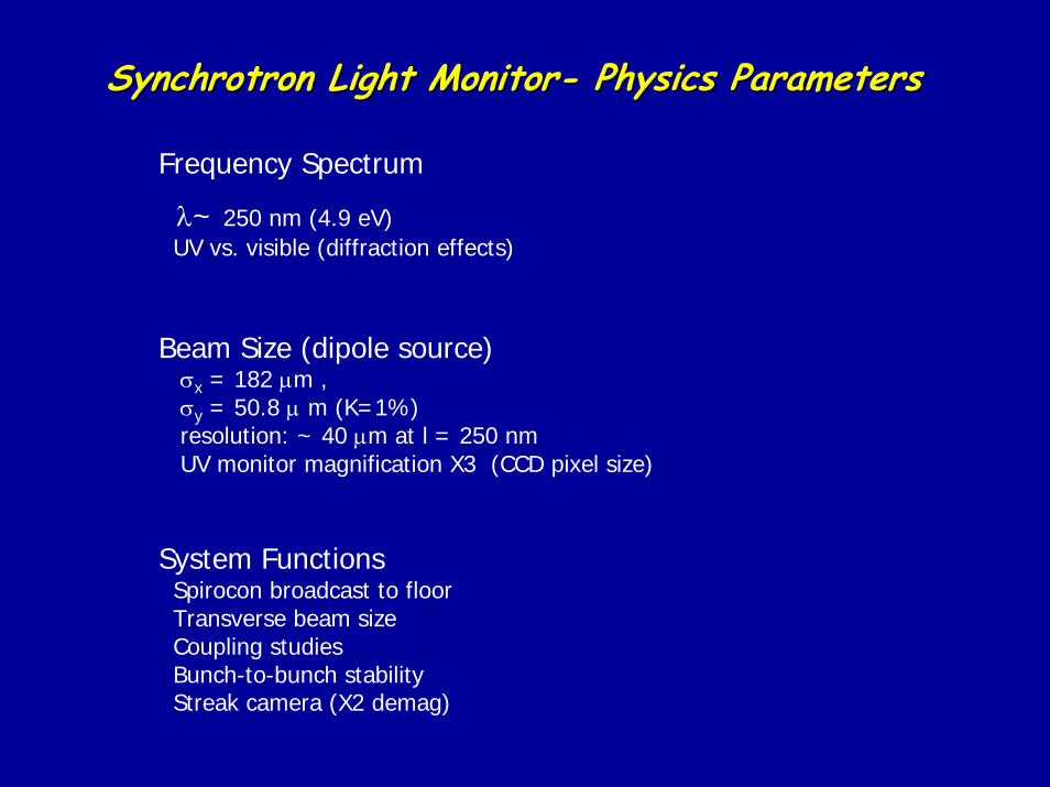
Synchrotron Light MonitorSynchrotron Light Monitor-- Physics ParametersPhysics Parameters
Frequency Spectrum
λ~ 250 nm (4.9 eV)UV vs. visible (diffraction effects)
Beam Size (dipole source)σx = 182 µm ,σy = 50.8 µ m (K=1%)resolution: ~ 40 µm at l = 250 nmUV monitor magnification X3 (CCD pixel size)
System FunctionsSpirocon broadcast to floorTransverse beam sizeCoupling studiesBunch-to-bunch stabilityStreak camera (X2 demag)
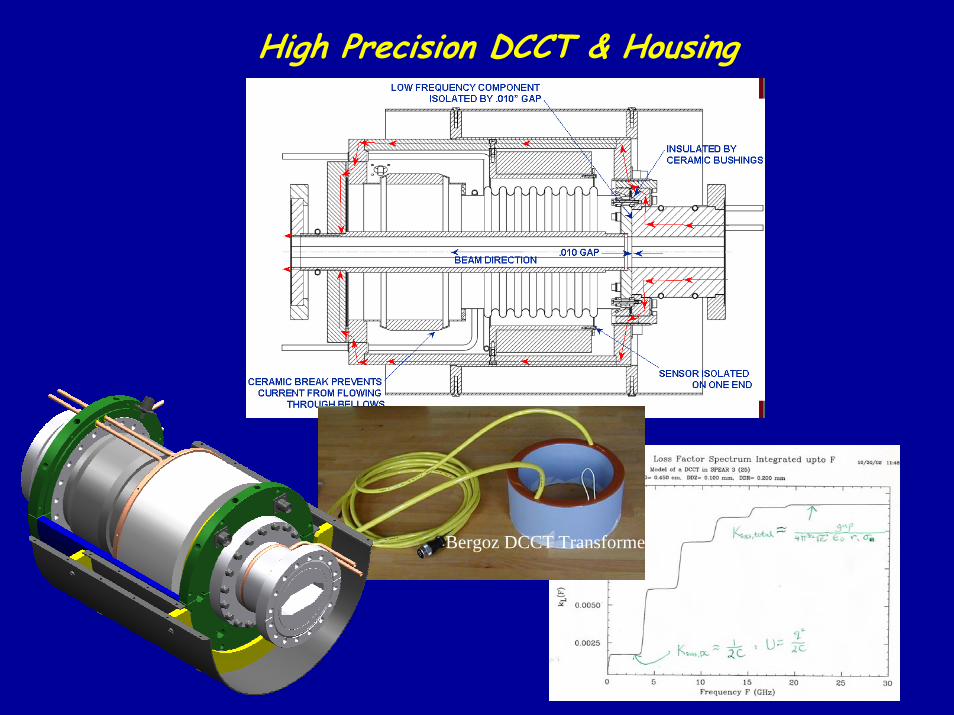
High Precision DCCT & Housing
Bergoz DCCT Transformer
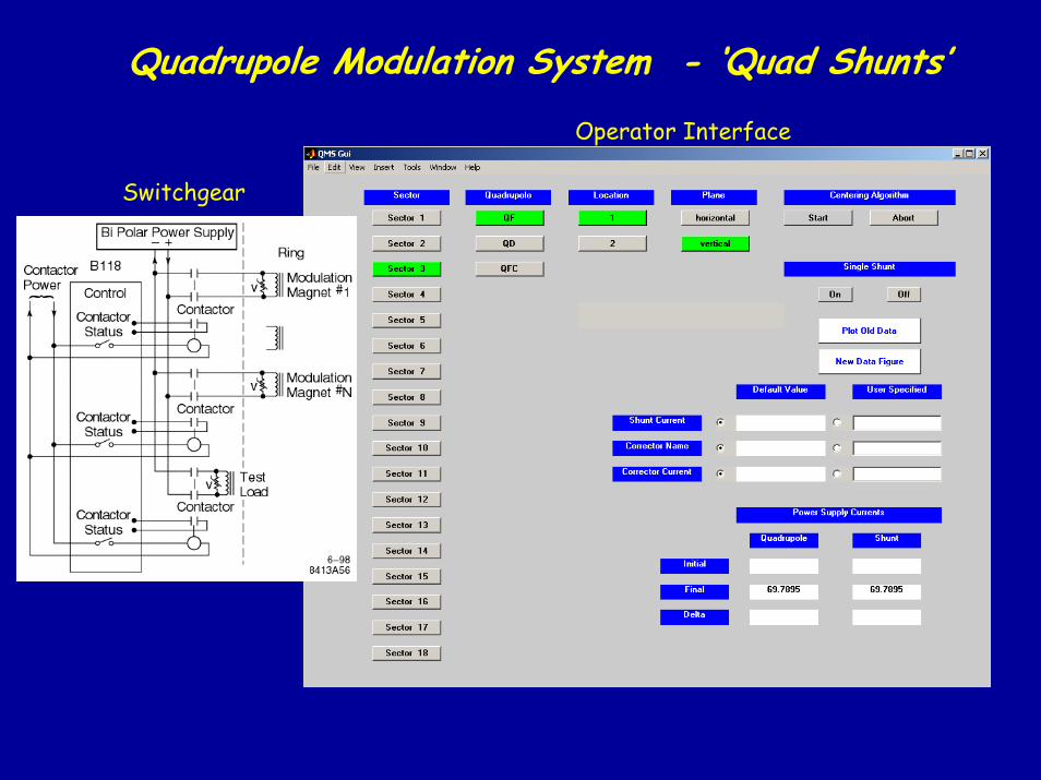
Quadrupole Modulation System - ‘Quad Shunts’
Operator Interface
Switchgear
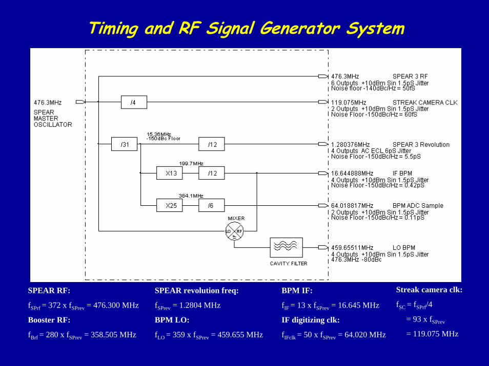
Timing and RF Signal Generator System
SPEAR RF:
fSPrf = 372 x fSPrev = 476.300 MHz
Booster RF:
fBrf = 280 x fSPrev = 358.505 MHz
SPEAR revolution freq:
fSPrev = 1.2804 MHz
BPM LO:
fLO = 359 x fSPrev = 459.655 MHz
BPM IF:
fIF = 13 x fSPrev = 16.645 MHz
IF digitizing clk:
fIFclk = 50 x fSPrev = 64.020 MHz
Streak camera clk:
fSC = fSPrf/4
= 93 x fSPrev
= 119.075 MHz
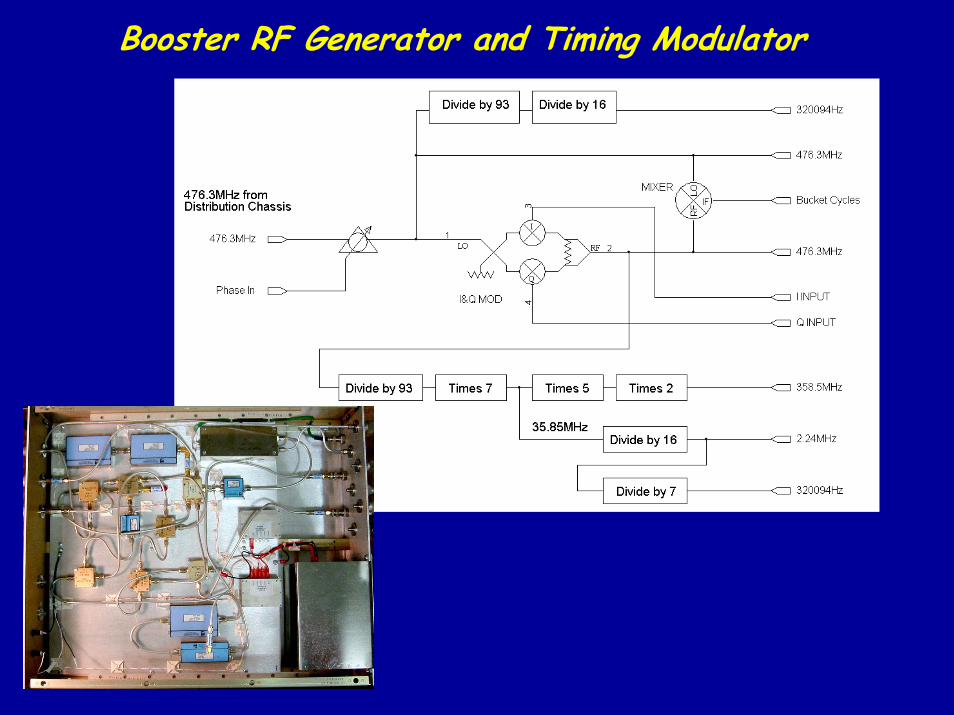
Booster RF Generator and Timing Modulator
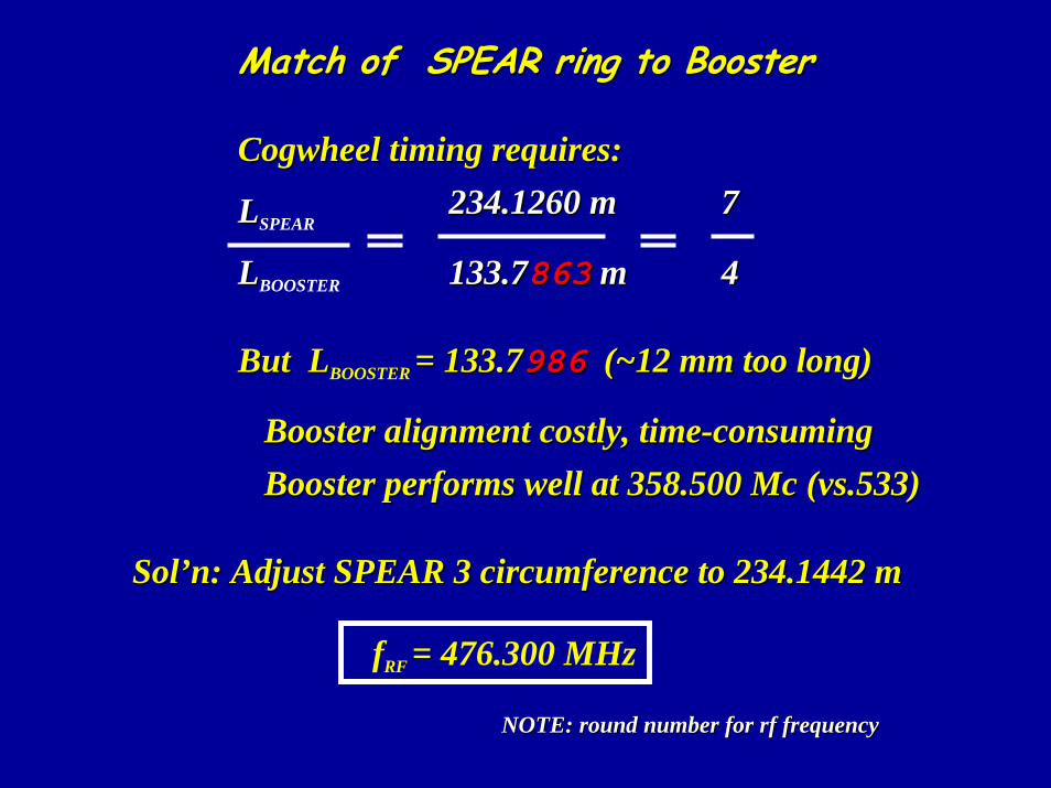
Match of SPEAR ring to BoosterMatch of SPEAR ring to Booster
Cogwheel timing requires:Cogwheel timing requires:
LLSPEAR
LLBOOSTER 44
77234.1260 m234.1260 m
133.7133.7863863 mm
But LBut LBOOSTER = 133.7= 133.7986986 (~12 mm too long)(~12 mm too long)
Booster alignment costly, timeBooster alignment costly, time--consumingconsumingBooster performs well at 358.500 Mc (vs.533)Booster performs well at 358.500 Mc (vs.533)
Sol’n: Adjust SPEAR 3 circumference to 234.1442 mSol’n: Adjust SPEAR 3 circumference to 234.1442 m
fRF = 476.300 MHz
NOTE: round number for rf frequencyNOTE: round number for rf frequency
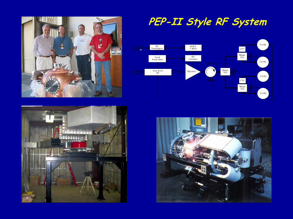
PEP-II Style RF System
MagicTee
Low-leve lRF
HVCrowbar
HVP S2 MVA
ACS witchgea r
FaultP rotection
476 MHz
RF Input
12kV/3
Klys tron
Circula tor
Load
Load
AC P ower
MagicTee
Cavity
Cavity
Load
270°
MagicTee
Cavity
Cavity
Load
270°
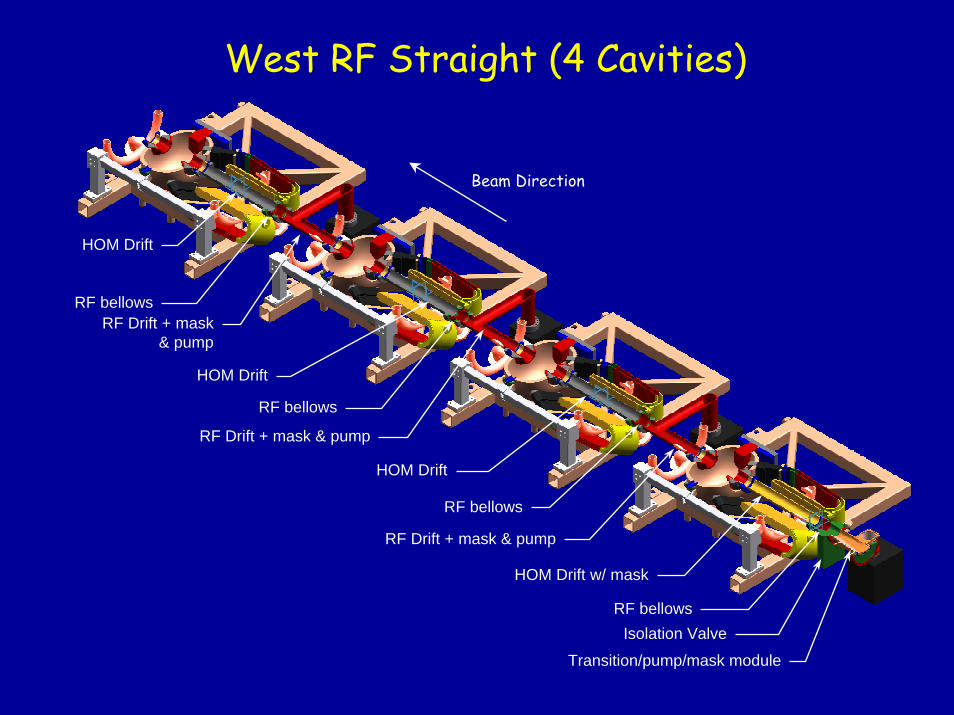
Transition/pump/mask module
HOM Drift w/ mask
RF Drift + mask & pump
HOM Drift
RF Drift + mask & pump
RF bellows
RF Drift + mask& pump
HOM Drift
HOM Drift
Isolation ValveRF bellows
RF bellows
RF bellows
West RF Straight (4 Cavities)
Beam Direction
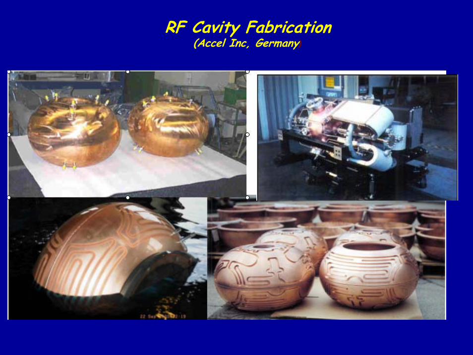
RF Cavity Fabrication(Accel Inc, Germany)
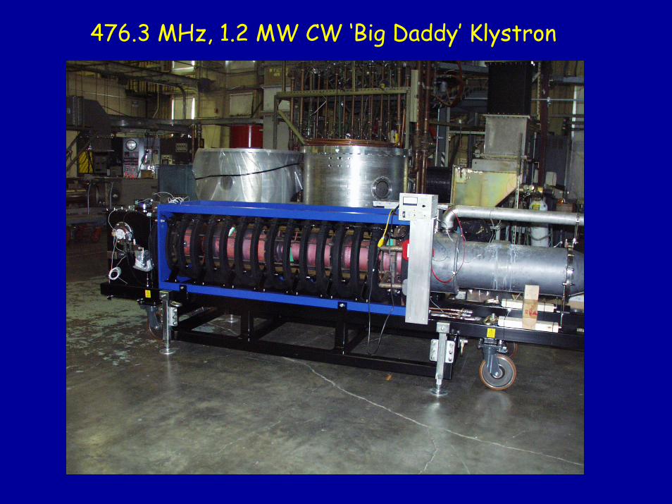
476.3 MHz, 1.2 MW CW ‘Big Daddy’ Klystron
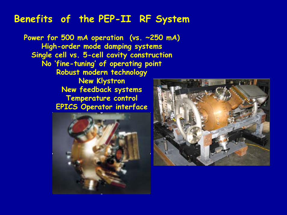
Benefits of the PEP-II RF System
Power for 500 mA operation (vs. ~250 mA)High-order mode damping systems
Single cell vs. 5-cell cavity constructionNo ‘fine-tuning’ of operating point
Robust modern technologyNew Klystron
New feedback systemsTemperature control
EPICS Operator interface
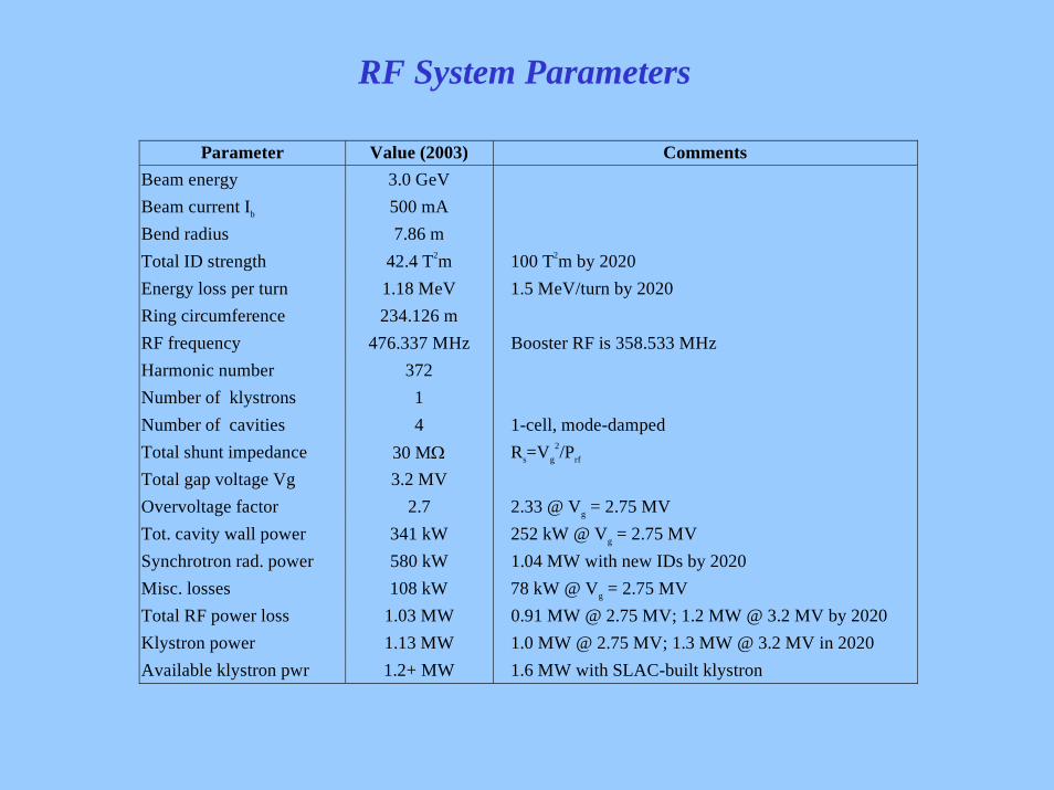
RF System Parameters
Parameter Value (2003) CommentsBeam energy 3.0 GeVBeam current Ib 500 mABend radius 7.86 mTotal ID strength 42.4 T2m 100 T2m by 2020Energy loss per turn 1.18 MeV 1.5 MeV/turn by 2020Ring circumference 234.126 mRF frequency 476.337 MHz Booster RF is 358.533 MHzHarmonic number 372Number of klystrons 1Number of cavities 4 1-cell, mode-dampedTotal shunt impedance 30 MΩ Rs=Vg
2/Prf
Total gap voltage Vg 3.2 MVOvervoltage factor 2.7 2.33 @ Vg = 2.75 MVTot. cavity wall power 341 kW 252 kW @ Vg = 2.75 MVSynchrotron rad. power 580 kW 1.04 MW with new IDs by 2020Misc. losses 108 kW 78 kW @ Vg = 2.75 MVTotal RF power loss 1.03 MW 0.91 MW @ 2.75 MV; 1.2 MW @ 3.2 MV by 2020Klystron power 1.13 MW 1.0 MW @ 2.75 MV; 1.3 MW @ 3.2 MV in 2020Available klystron pwr 1.2+ MW 1.6 MW with SLAC-built klystron
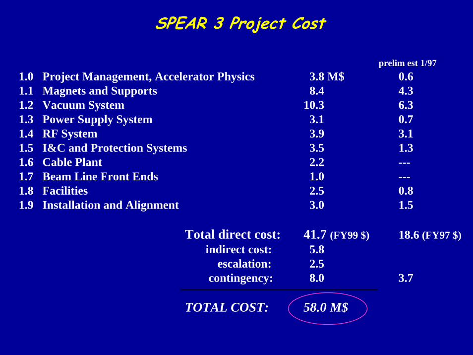
prelim est 1/971.0 Project Management, Accelerator Physics 3.8 M$ 0.61.1 Magnets and Supports 8.4 4.31.2 Vacuum System 10.3 6.31.3 Power Supply System 3.1 0.71.4 RF System 3.9 3.11.5 I&C and Protection Systems 3.5 1.31.6 Cable Plant 2.2 ---1.7 Beam Line Front Ends 1.0 ---1.8 Facilities 2.5 0.81.9 Installation and Alignment 3.0 1.5
Total direct cost: 41.7 (FY99 $) 18.6 (FY97 $)indirect cost: 5.8
escalation: 2.5contingency: 8.0 3.7
TOTAL COST: 58.0 M$
SPEAR 3 Project Cost
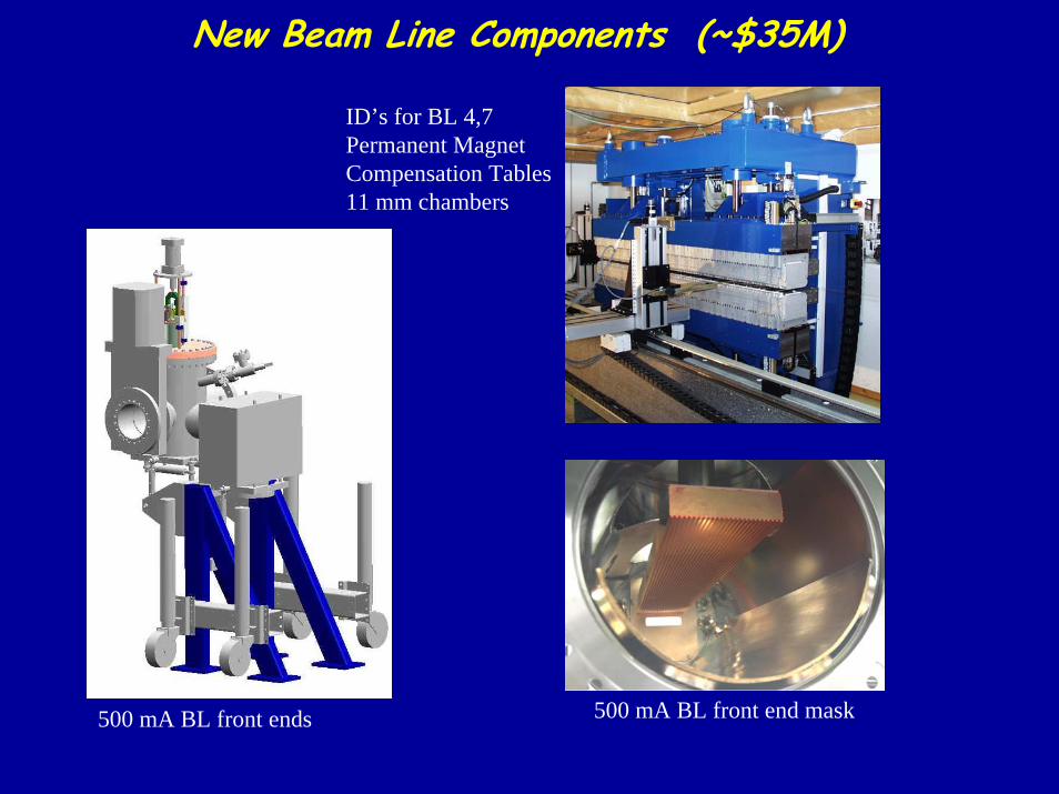
New Beam Line Components (~$35M)
500 mA BL front ends 500 mA BL front end mask
ID’s for BL 4,7Permanent MagnetCompensation Tables11 mm chambers

Major Reviews and ReferencesNov 3-5, 1997 Director’s Review
July 28-30, 1998 Department of Energy (Lehman Review)
Sept 14-15, 1999 “ “ “
June 13-14, 2000 “ “ “
July 24-25, 2001 “ “ “
July 16-18, 2002 “ “ “
SPEAR 3 Design Report August 1999
SPEAR 3 Quarterly Reports http://www-ssrl.slac.stanford.edu/spear3/spear3_main_page.htm
SPEAR 3 Publications “ “ “ “
SPEAR 3 Technical “ “ “ “
Magnet Photo Gallery http://www-ssrl.slac.stanford.edu/~nli
Vacuum Photo Gallery logon slacnt, winsan1, ssrl-sp3/transfer/sp3vacshop
Power Supply .xls q:groups/accel/supplies
RF System Particle Accelerator Conferences (Schwarz, Rimmer, Hill, Allison, Corredoura)
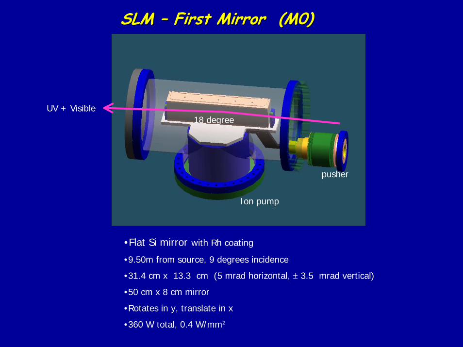
SLM SLM –– First Mirror (M0)First Mirror (M0)
18 degree
pusher
Ion pump
UV + Visible
•Flat Si mirror with Rh coating
•9.50m from source, 9 degrees incidence
•31.4 cm x 13.3 cm (5 mrad horizontal, ± 3.5 mrad vertical)
•50 cm x 8 cm mirror
•Rotates in y, translate in x
•360 W total, 0.4 W/mm2