
OPERATING AND INSTALLATION INSTRUCTIONS -...
24
05/2014 OPERATING AND INSTALLATION INSTRUCTIONS • ISTRUZIONI D’USO E D’INSTALLAZIONE NOTICE D’UTILISATION ET D’INSTALLATION • BEDIENUNGS-UND INSTALLATIONSANLEITUNG INSTRUCCIONES DE USO Y INSTALACION • MANUAL DE INSTRUÇÕES E INSTALAÇÃO ΟΔΗΓΙΕΣ ΧΡΗΣΗΣ και ΕΓΚΑΤΑΣΤΑΣΗΣ Emix Emix TANK 220 Emix TANK 300 EG I F D E P GR
Transcript of OPERATING AND INSTALLATION INSTRUCTIONS -...
EMIX
EMIX TANK 220 EMIX TANK 300
05/2014
OPERATING AND INSTALLATION INSTRUCTIONS • ISTRUZIONI D’USO E D’INSTALLAZIONENOTICE D’UTILISATION ET D’INSTALLATION • BEDIENUNGS-UND INSTALLATIONSANLEITUNG
INSTRUCCIONES DE USO Y INSTALACION • MANUAL DE INSTRUÇÕES E INSTALAÇÃOΟΔΗΓΙΕΣ ΧΡΗΣΗΣ και ΕΓΚΑΤΑΣΤΑΣΗΣ
Emix
Emix TANK 220 Emix TANK 300
EG
I
F
D
E
P
GR
2
EG
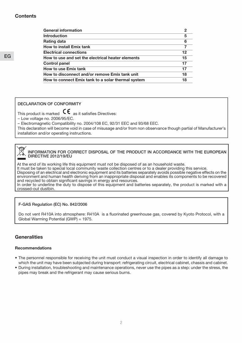
Contents
General information 2Introduction 5Rating data 6How to install Emix tank 7Electrical connections 12How to use and set the electrical heater elements 15 Control panel 17How to use Emix tank 17How to disconnect and/or remove Emix tank unit 18How to connect Emix tank to a solar thermal system 18
DECLARATION OF CONFORMITY
This product is marked as it satisfies Directives:– Low voltage no. 2006/95/EC.– Electromagnetic Compatibility no. 2004/108 EC, 92/31 EEC and 93/68 EEC. This declaration will become void in case of misusage and/or from non observance though partial of Manufacturer’s installation and/or operating instructions.
INFORMATION FOR CORRECT DISPOSAL OF THE PRODUCT IN ACCORDANCE WITH THE EUROPEAN DIRECTIVE 2012/19/EU
At the end of its working life this equipment must not be disposed of as an household waste.It must be taken to special local community waste collection centres or to a dealer providing this service.Disposing of an electrical and electronic equipment and its batteries separately avoids possible negative effects on the environment and human health deriving from an inappropriate disposal and enables its components to be recovered and recycled to obtain significant savings in energy and resources. In order to underline the duty to dispose of this equipment and batteries separately, the product is marked with a crossed-out dustbin.
F-GAS Regulation (EC) No. 842/2006
Do not vent R410A into atmosphere: R410A is a fluorinated greenhouse gas, covered by Kyoto Protocol, with a Global Warming Potential (GWP) = 1975.
Generalities
Recommendations
•Thepersonnelresponsibleforreceivingtheunitmustconductavisualinspectioninordertoidentifyalldamagetowhich the unit may have been subjected during transport: refrigerating circuit, electrical cabinet, chassis and cabinet.
•Duringinstallation,troubleshootingandmaintenanceoperations,neverusethepipesasastep:underthestress,thepipes may break and the refrigerant may cause serious burns.
3
EG
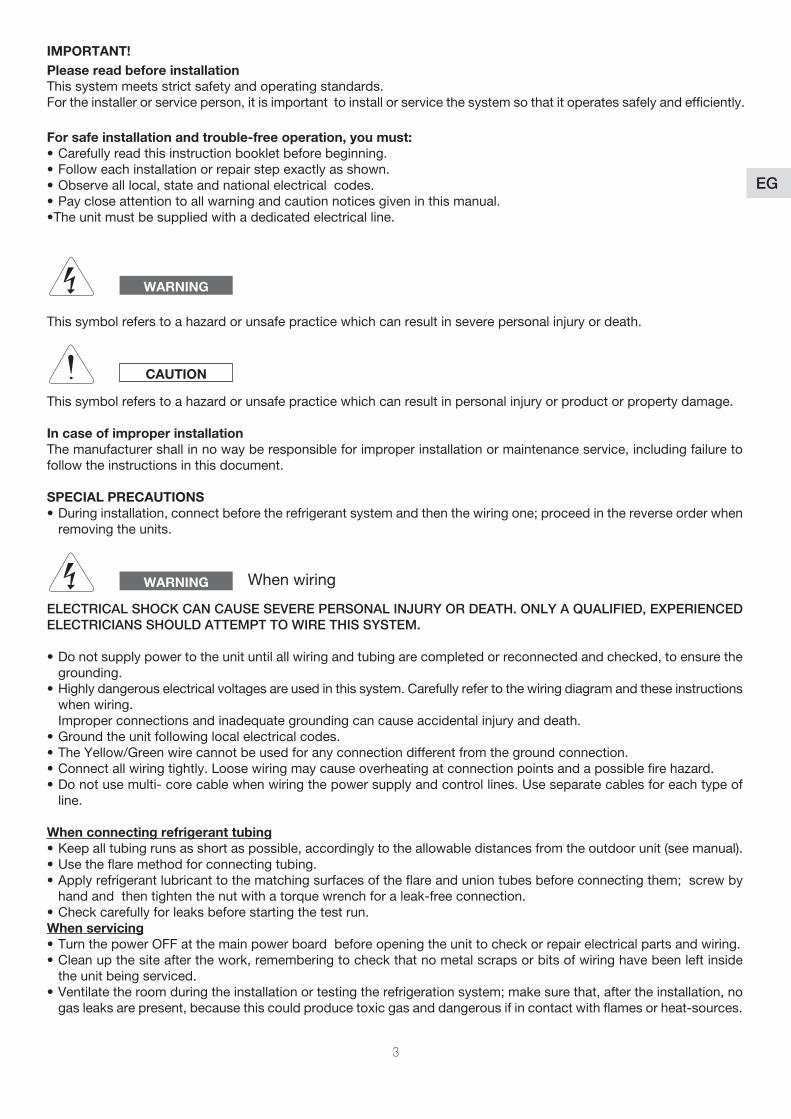
This symbol refers to a hazard or unsafe practice which can result in severe personal injury or death.
This symbol refers to a hazard or unsafe practice which can result in personal injury or product or property damage.
In case of improper installationThe manufacturer shall in no way be responsible for improper installation or maintenance service, including failure to follow the instructions in this document.
SPECIAL PRECAUTIONS•Duringinstallation,connectbeforetherefrigerantsystemandthenthewiringone;proceedinthereverseorderwhen
removing the units.
ELECTRICAL SHOCK CAN CAUSE SEVERE PERSONAL INJURY OR DEATH. ONLY A QUALIFIED, EXPERIENCED ELECTRICIANS SHOULD ATTEMPT TO WIRE THIS SYSTEM.
•Donotsupplypowertotheunituntilallwiringandtubingarecompletedorreconnectedandchecked,toensurethegrounding.
•Highlydangerouselectricalvoltagesareusedinthissystem.Carefullyrefertothewiringdiagramandtheseinstructionswhen wiring.
Improper connections and inadequate grounding can cause accidental injury and death.•Groundtheunitfollowinglocalelectricalcodes.•TheYellow/Greenwirecannotbeusedforanyconnectiondifferentfromthegroundconnection.•Connectallwiringtightly.Loosewiringmaycauseoverheatingatconnectionpointsandapossiblefirehazard.•Donotusemulti-corecablewhenwiringthepowersupplyandcontrollines.Useseparatecablesforeachtypeof
line.
When connecting refrigerant tubing•Keepalltubingrunsasshortaspossible,accordingly to the allowable distances from the outdoor unit (see manual).•Usetheflaremethodforconnectingtubing.•Applyrefrigerantlubricanttothematchingsurfacesoftheflareanduniontubesbeforeconnectingthem;screwby
hand and then tighten the nut with a torque wrench for a leak-free connection.•Checkcarefullyforleaksbeforestartingthetestrun.When servicing•TurnthepowerOFFatthemainpowerboardbeforeopeningtheunittocheckorrepairelectricalpartsandwiring.•Cleanupthesiteafterthework,rememberingtocheckthatnometalscrapsorbitsofwiringhavebeenleftinside
the unit being serviced.•Ventilatetheroomduringtheinstallationortestingtherefrigerationsystem;makesurethat,aftertheinstallation,no
gas leaks are present, because this could produce toxic gas and dangerous if in contact with flames or heat-sources.
WARNING
CAUTION
WARNING When wiring
IMPORTANT!Please read before installationThis system meets strict safety and operating standards.Fortheinstallerorserviceperson,itisimportanttoinstallorservicethesystemsothatitoperatessafelyandefficiently.
For safe installation and trouble-free operation, you must:•Carefullyreadthisinstructionbookletbeforebeginning.•Followeachinstallationorrepairstepexactlyasshown.•Observealllocal,stateandnationalelectricalcodes.•Paycloseattentiontoallwarningandcautionnoticesgiveninthismanual.•Theunitmustbesuppliedwithadedicatedelectricalline.
4
EG
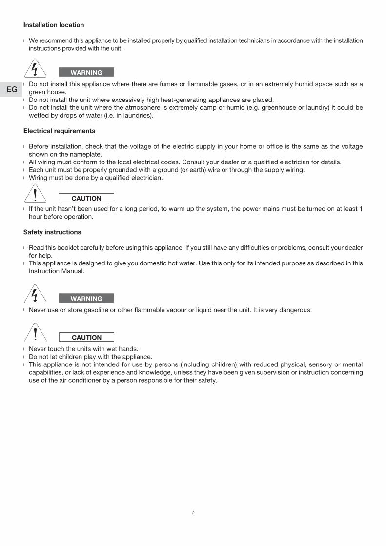
Installation location
l We recommend this appliance to be installed properly by qualified installation technicians in accordance with the installation instructions provided with the unit.
l Do not install this appliance where there are fumes or flammable gases, or in an extremely humid space such as a green house.
l Do not install the unit where excessively high heat-generating appliances are placed.l Do not install the unit where the atmosphere is extremely damp or humid (e.g. greenhouse or laundry) it could be
wetted by drops of water (i.e. in laundries).
Electrical requirements
l Before installation, check that the voltage of the electric supply in your home or office is the same as the voltage shown on the nameplate.
l All wiring must conform to the local electrical codes. Consult your dealer or a qualified electrician for details.l Each unit must be properly grounded with a ground (or earth) wire or through the supply wiring.l Wiring must be done by a qualified electrician.
l If the unit hasn’t been used for a long period, to warm up the system, the power mains must be turned on at least 1 hour before operation.
Safety instructions
l Read this booklet carefully before using this appliance. If you still have any difficulties or problems, consult your dealer for help.
l Thisapplianceisdesignedtogiveyoudomestichotwater.UsethisonlyforitsintendedpurposeasdescribedinthisInstruction Manual.
l Never use or store gasoline or other flammable vapour or liquid near the unit. It is very dangerous.
l Never touch the units with wet hands.l Do not let children play with the appliance.l This appliance is not intended for use by persons (including children) with reduced physical, sensory or mental
capabilities, or lack of experience and knowledge, unless they have been given supervision or instruction concerning use of the air conditioner by a person responsible for their safety.
WARNING
WARNING
CAUTION
CAUTION
5
EG
Introduction
Emix tank is the innovative indoor unit in the iSeries system range, able to provide domestic hot water from a thermo-dynamic source all year round, i.e. independently of the system’s operating mode.
Emix tank is a new component of the iSeries system which is added to the very broad range of indoor units.
The purpose of Emix tank is to produce domestic hot water through storage, using the energy produced directly from the heat pump (therefore renewable energy) and providing the service at the same time as heating and cooling the environments, thanks to the various air and/or hydronic indoor units of the iSeries range.
Emix tank 220 & 300 lt
Emix tank 220 lt and 300 lt offering you a complete solution, including:• theEmixconceptsandcomponents• atankof220or300litersmadeinStainlessSteelAISI444(currentlythebest)• thesolarcoilinStainlessSteelAISI316Ltobeconnectedtoathirdpartssolarpanelsystem• threeper1kWelectricelementsmanagedbytheelectronicsofEmixtankormanuallybytheendusers• themixingvalvetomanageproperlythehotwatertemperature• electric connections to manage the tank by iSeries and to power it by single phase or three phase power supply
Emix tank is both a proper heat pump tank and a full feature electrical water heater
Emix tank must be connected to an outdoor unit of the iSeries range equipped with special software and a specific connection dedicated to Emix tank. The compatible outdoor units are all the following outdoor units of the iSeries range with EMX port (*)
(*) All the previous models does not support Emix tank.
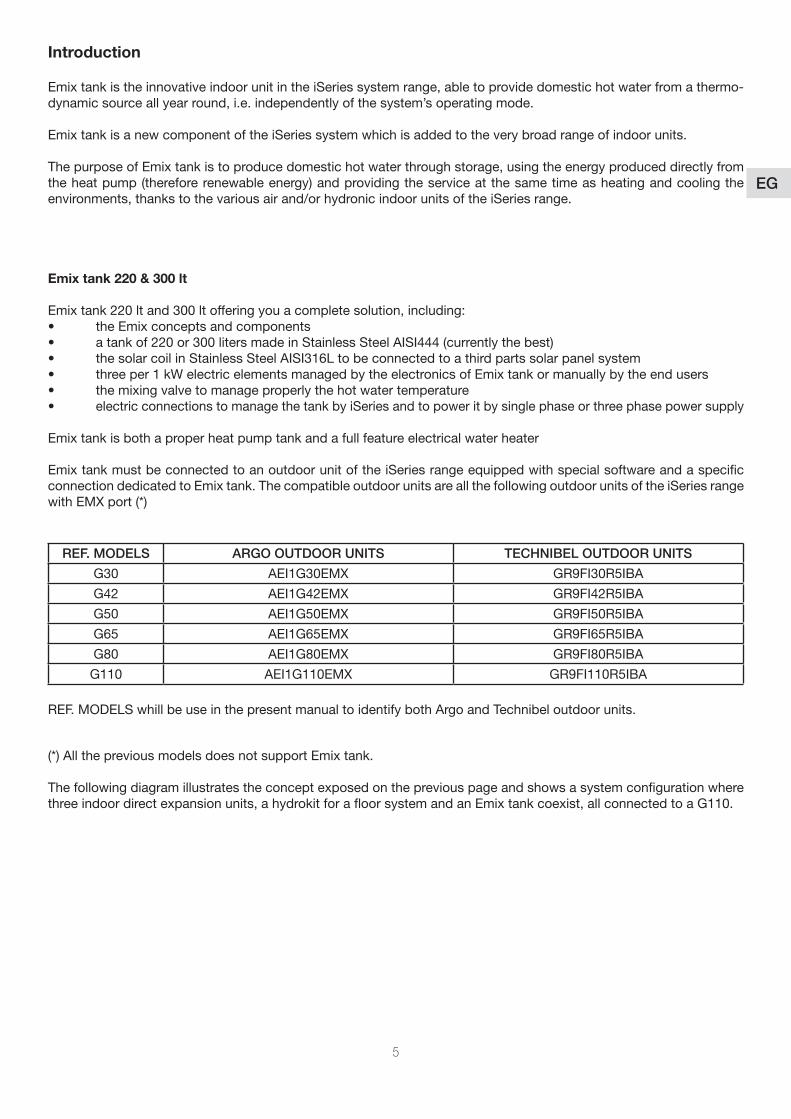
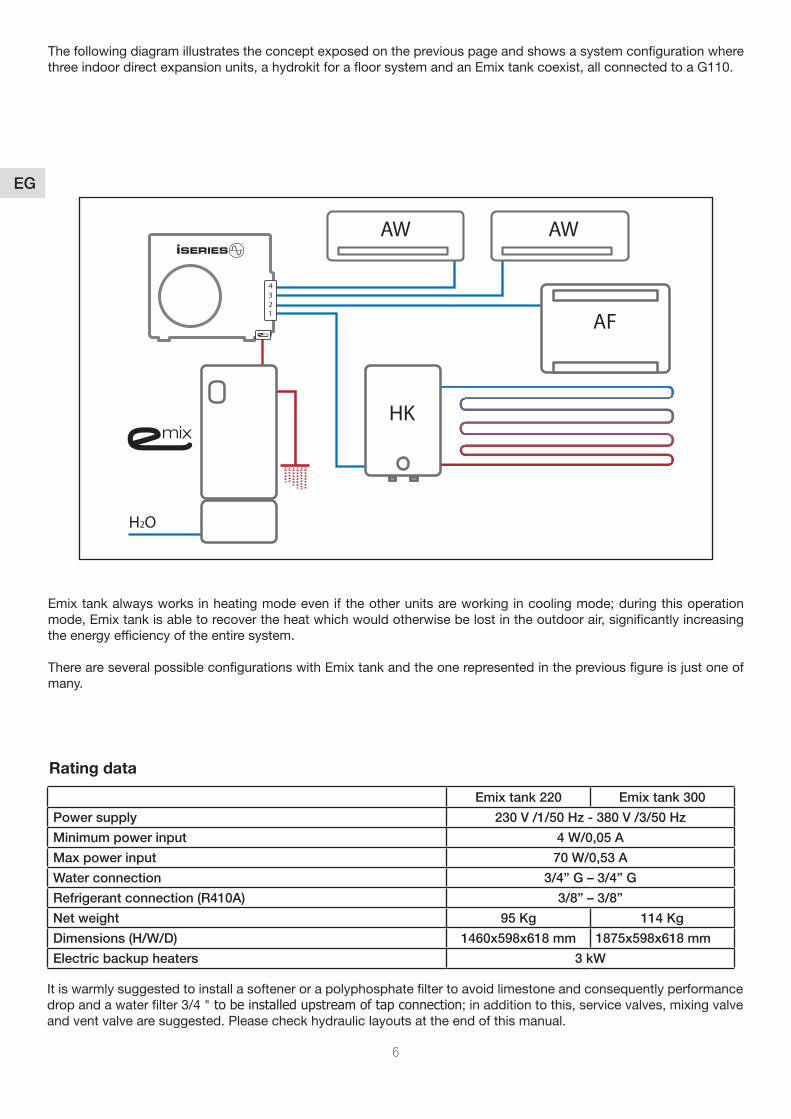
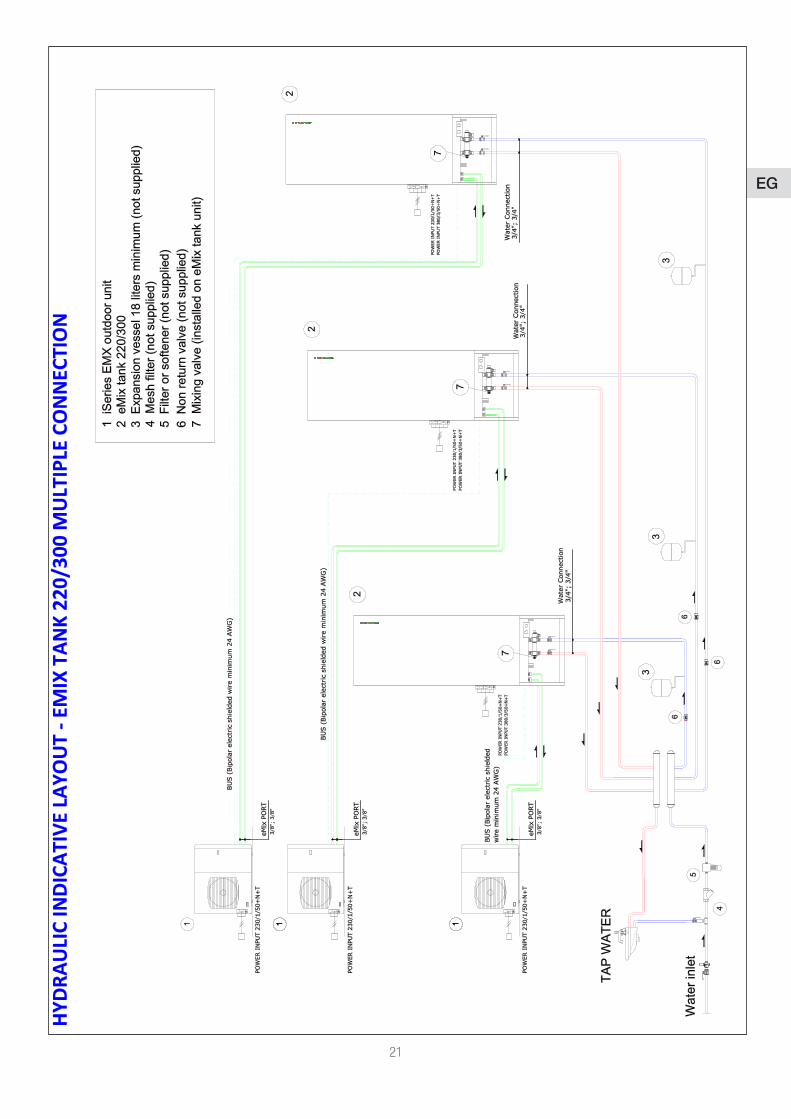
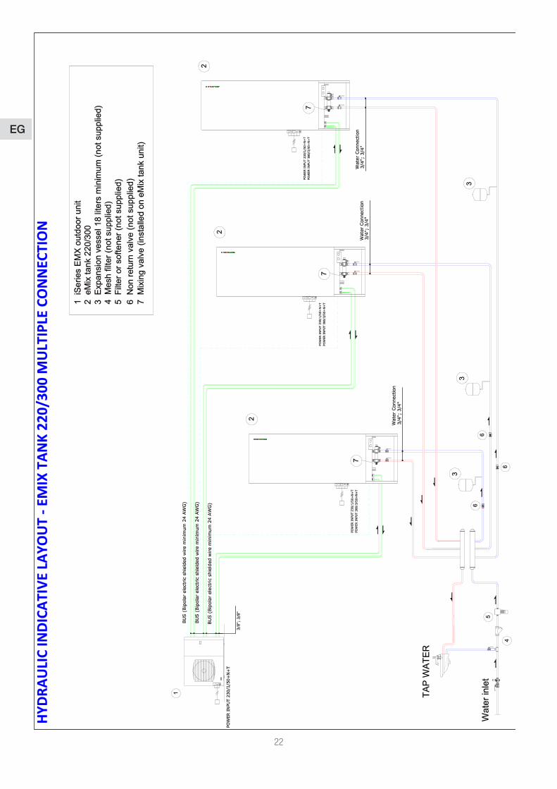
The following diagram illustrates the concept exposed on the previous page and shows a system configuration where three indoor direct expansion units, a hydrokit for a floor system and an Emix tank coexist, all connected to a G110.
REF. MODELS ARGO OUTDOOR UNITS TECHNIBEL OUTDOOR UNITS
G30 AEI1G30EMX GR9FI30R5IBA
G42 AEI1G42EMX GR9FI42R5IBA
G50 AEI1G50EMX GR9FI50R5IBA
G65 AEI1G65EMX GR9FI65R5IBA
G80 AEI1G80EMX GR9FI80R5IBA
G110 AEI1G110EMX GR9FI110R5IBA
REF.MODELSwhillbeuseinthepresentmanualtoidentifybothArgoandTechnibeloutdoorunits.
6
EG
Emixtankalwaysworksinheatingmodeeveniftheotherunitsareworkingincoolingmode;duringthisoperationmode, Emix tank is able to recover the heat which would otherwise be lost in the outdoor air, significantly increasing the energy efficiency of the entire system.
There are several possible configurations with Emix tank and the one represented in the previous figure is just one of many.
The following diagram illustrates the concept exposed on the previous page and shows a system configuration where three indoor direct expansion units, a hydrokit for a floor system and an Emix tank coexist, all connected to a G110.
Rating data
Emix tank 220 Emix tank 300
Power supply 230 V /1/50 Hz - 380 V /3/50 Hz
Minimum power input 4 W/0,05 A
Max power input 70 W/0,53 A
Water connection 3/4” G – 3/4” G
Refrigerant connection (R410A) 3/8” – 3/8”
Net weight 95 Kg 114 Kg
Dimensions (H/W/D) 1460x598x618 mm 1875x598x618 mm
Electric backup heaters 3 kW
It is warmly suggested to install a softener or a polyphosphate filter to avoid limestone and consequently performance drop and a water filter 3/4 " to be installed upstream of tap connection;inadditiontothis,servicevalves,mixingvalveand vent valve are suggested. Please check hydraulic layouts at the end of this manual.
H2O
AW AW
AF
HK
4321
7
EG
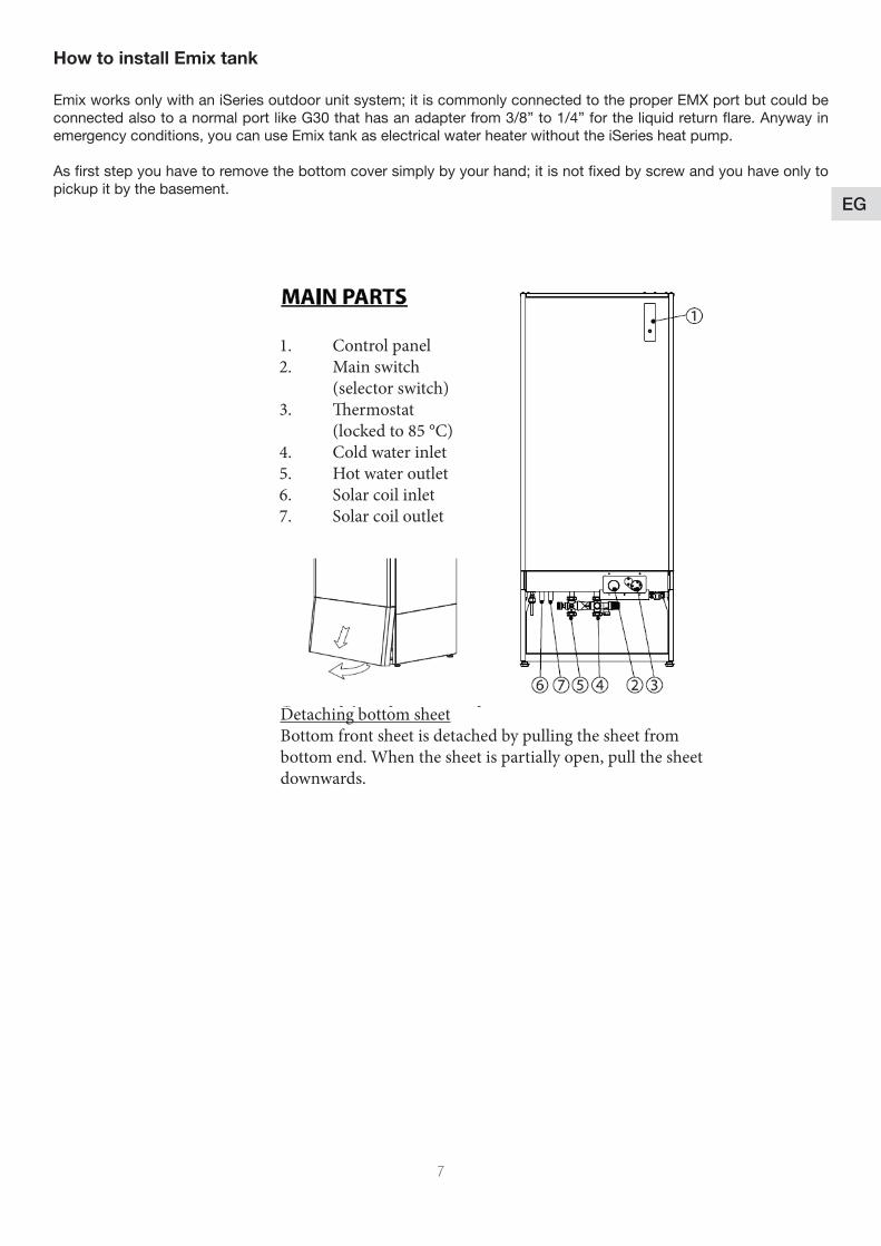
How to install Emix tank
EmixworksonlywithaniSeriesoutdoorunitsystem;itiscommonlyconnectedtotheproperEMXportbutcouldbeconnected also to a normal port like G30 that has an adapter from 3/8” to 1/4” for the liquid return flare. Anyway in emergency conditions, you can use Emix tank as electrical water heater without the iSeries heat pump.
Asfirststepyouhavetoremovethebottomcoversimplybyyourhand;itisnotfixedbyscrewandyouhaveonlytopickup it by the basement.
1. Control panel2. Main switch (selector switch)3. Thermostat (locked to 85 °C)4. Cold water inlet5. Hot water outlet6. Solar coil inlet7. Solar coil outlet
Detaching bottom sheetBottom front sheet is detached by pulling the sheet from bottom end. When the sheet is partially open, pull the sheet downwards.
8
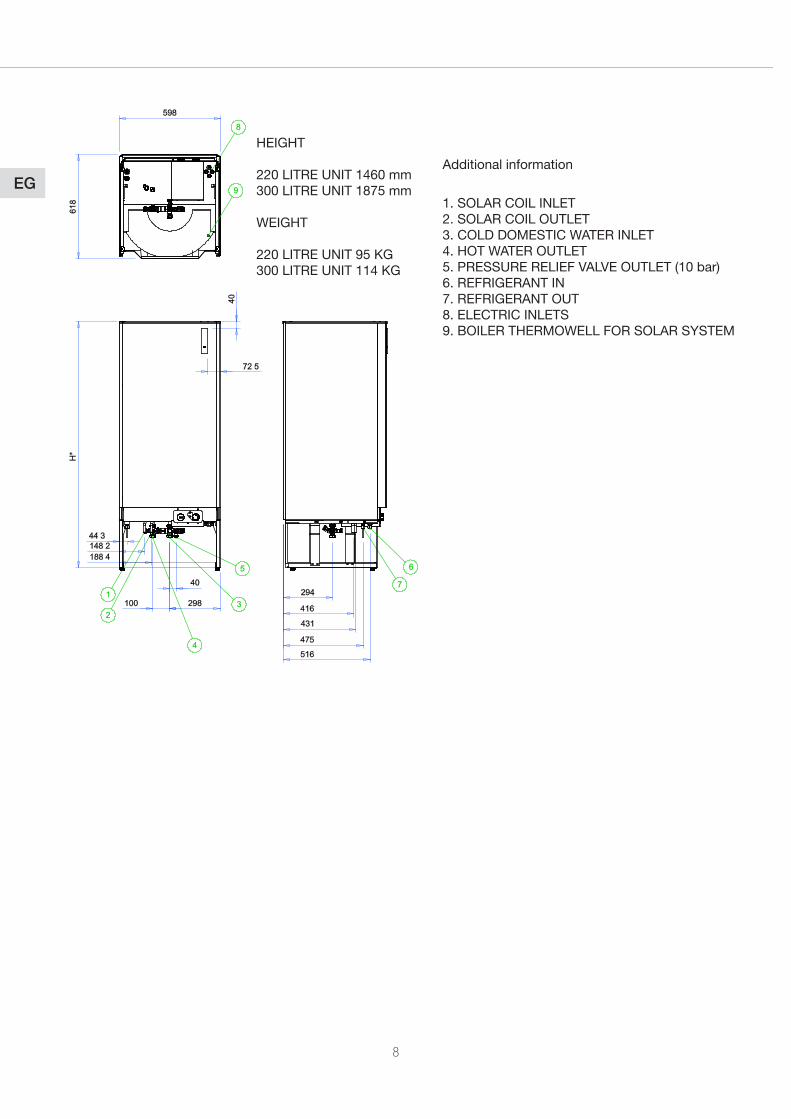
EG1.SOLARCOILINLET2.SOLARCOILOUTLET3.COLDDOMESTICWATERINLET4.HOTWATEROUTLET5.PRESSURERELIEFVALVEOUTLET(10bar)6.REFRIGERANTIN7.REFRIGERANTOUT8. ELECTRIC INLETS9.BOILERTHERMOWELLFORSOLARSYSTEM
HEIGHT 220LITREUNIT1460mm300LITREUNIT1875mm
WEIGHT 220LITREUNIT95KG300LITREUNIT114KG
Additional information
9
EG
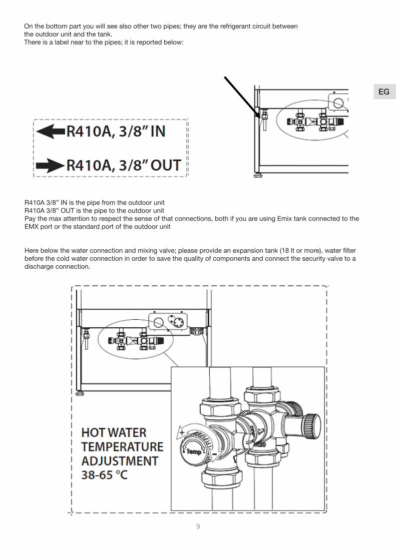
Onthebottompartyouwillseealsoothertwopipes;theyaretherefrigerantcircuitbetweenthe outdoor unit and the tank.Thereisalabelneartothepipes;itisreportedbelow:
R410A 3/8” IN is the pipe from the outdoor unitR410A3/8”OUTisthepipetotheoutdoorunitPay the max attention to respect the sense of that connections, both if you are using Emix tank connected to the EMX port or the standard port of the outdoor unit
Herebelowthewaterconnectionandmixingvalve;pleaseprovideanexpansiontank(18ltormore),waterfilterbefore the cold water connection in order to save the quality of components and connect the security valve to a discharge connection.
10
EG
And now follow the next steps with max care:
• ClosethevalvesontheEMXportofoutdoorunit(G42,G50,G65,G80,G110).• DisconnectthebypassfromthevalvesontheEMXport(takecareofitbecauseyouwillneeditincaseof dismount of Emix tank unit).• ConnectthecopperpipesbetweenoutdoorunitandEmixtankfor(G42,G50,G65,G80,G110). (warmly suggested a strong insulation in order to avoid loses of precious energy).• Performthevacuumprocedure.• OpenthevalvesofEMXport.• Connectthewatertothetank(Itisrecommendedtoinstallanexpansiontankof18lt,servicevalvesonthe connections of the water circuit in order to make installation and maintenance operations easier and a pipe on the high pressure safety output of the security valve).• Itiswarmlysuggestedtoinstallthefilterupstreamthewatercircuitandasoftenerorpolyphosphatefilterto avoid limestone.
Refrigerant Circuit
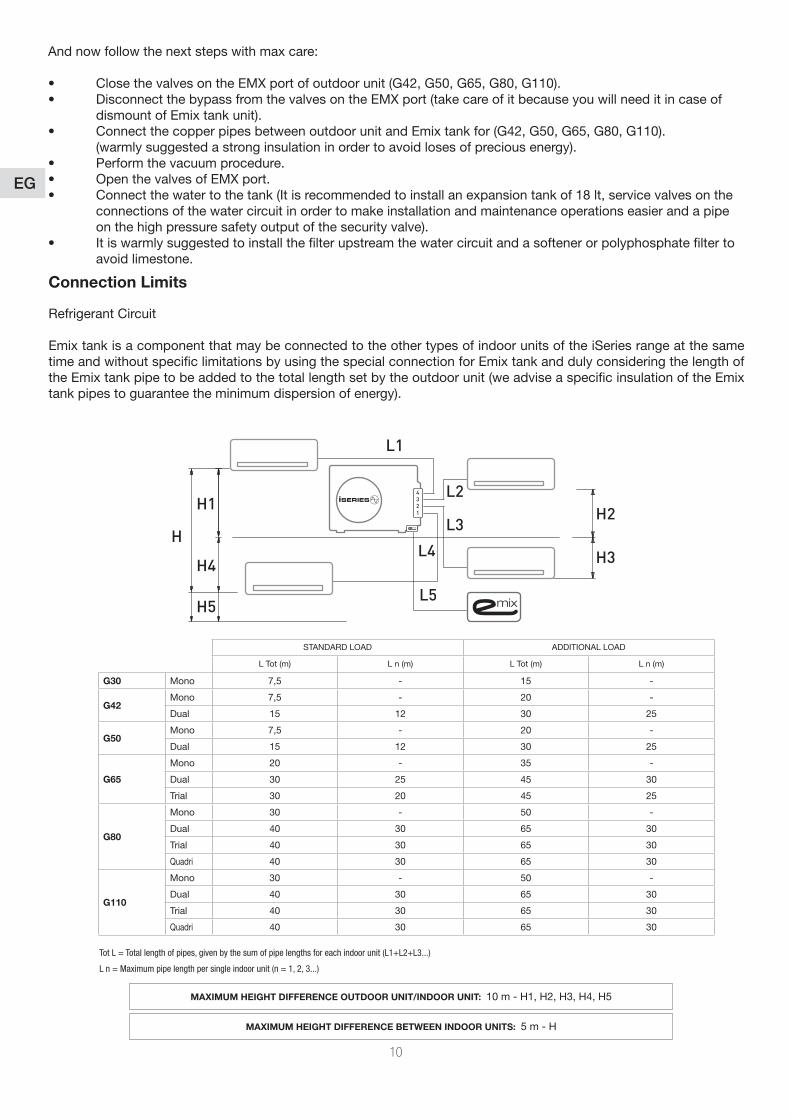
Emix tank is a component that may be connected to the other types of indoor units of the iSeries range at the same time and without specific limitations by using the special connection for Emix tank and duly considering the length of the Emix tank pipe to be added to the total length set by the outdoor unit (we advise a specific insulation of the Emix tank pipes to guarantee the minimum dispersion of energy).
Connection Limits
4321
L5
L4
L3
L2
L1
H1
H4
H5
HH2
H3
STANDARDLOAD ADDITIONALLOAD
L Tot (m) L n (m) L Tot (m) L n (m)
G30 Mono 7,5 - 15 -
G42Mono 7,5 - 20 -
Dual 15 12 30 25
G50Mono 7,5 - 20 -
Dual 15 12 30 25
G65
Mono 20 - 35 -
Dual 30 25 45 30
Trial 30 20 45 25
G80
Mono 30 - 50 -
Dual 40 30 65 30
Trial 40 30 65 30
Quadri 40 30 65 30
G110
Mono 30 - 50 -
Dual 40 30 65 30
Trial 40 30 65 30
Quadri 40 30 65 30
MAXIMUM HEIGHT DIFFERENCE OUTDOOR UNIT/INDOOR UNIT: 10m-H1,H2,H3,H4,H5
MAXIMUM HEIGHT DIFFERENCE BETWEEN INDOOR UNITS: 5m-H
Tot L = Total length of pipes, given by the sum of pipe lengths for each indoor unit (L1+L2+L3...)
L n = Maximum pipe length per single indoor unit (n = 1, 2, 3...)
11
EGExample n° 1
• Outdoorunit:G80• Numberofindoorunits:4sizeA(quadriapplication)• Totalindoorunittubinglength:30meters• Emixtanktubinglength:5meters• Totaltubinglength(includingEmixtank):35meters
G80 limits in quadri application is 40 meters. The system is ok, without additional load.
Example n° 2• Outdoorunit:G80• Numberofindoorunits:4sizeA(quadriapplication)• Totalindoorunittubinglength:50meters• Emixtanktubinglength:7meters• Totaltubinglength(includingEmixtank):57meters
G80limitsinquadriapplicationis65meters,withadditionalload.Youhavetoadd:15g/mx17m.
Choose the configuration by the number of indoor units (excluding Emix tank unit) and by the outdoor unit model.• Check connection limits including Emix tank unit distance• Additional refrigerant charge for Emix tank line ( if needed) is : 15 g/m
Lenght and elevation limits for Emix tank unit are the same as those of standard indoor units.
12
EG
Electrical connections
Emix tank must always be connected to the electrical power supply in a separate manner compared to the connection of the outdoor unit of the iSeries system.
General•Theacceptablevoltagevariationis:±10%duringoperation.•Theelectricalconnectionconduitsmustbefixed.•Class1unit.
Power supply•Thepowersupplymustcomefromanisolationandelectricprotectiondevice(notsupplied)inaccordancewithexisting
regulations.•Theinstallationmustbeprotectedbyadouble-polecircuit-breaker(notincluded).
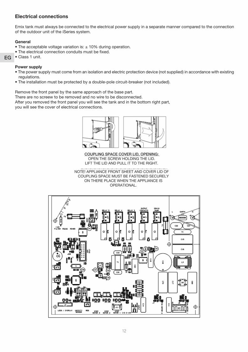
Remove the front panel by the same approach of the base part. There are no screew to be removed and no wire to be disconnected.After you removed the front panel you will see the tank and in the bottom right part, you will see the cover of electrical connections.
COUPLING SPACE COVER LID, OPENING: OPENTHESCREWHOLDINGTHELID.
LIFTTHELIDANDPULLITTOTHERIGHT.
NOTE!APPLIANCEFRONTSHEETANDCOVERLIDOFCOUPLINGSPACEMUSTBEFASTENEDSECURELY
ONTHEREPLACEWHENTHEAPPLIANCEISOPERATIONAL.
13
EG
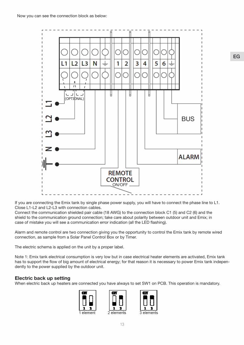
Now you can see the connection block as below:
If you are connecting the Emix tank by single phase power supply, you will have to connect the phase line to L1. Close L1-L2 and L2-L3 with connection cables.Connect the communication shielded pair cable (18 AWG) to the connection block C1 (5) and C2 (6) and theshieldtothecommunicationgroundconnection;takecareaboutpolaritybetweenoutdoorunitandEmix;incase of mistake you will see a communication error indication (all the LED flashing).
Alarm and remote control are two connection giving you the opportunity to control the Emix tank by remote wired connection, as sample from a Solar Panel Control Box or by Timer.
The electric schema is applied on the unit by a proper label.
Note 1: Emix tank electrical consumption is very low but in case electrical heater elements are activated, Emix tank hastosupporttheflowofbigamountofelectricalenergy;forthatreasonitisnecessarytopowerEmixtankindepen-dently to the power supplied by the outdoor unit.
Electric back up settingWhen electric back up heaters are connected you have always to set SW1 on PCB. This operation is mandatory.
BUS
ON/OFF
(OPTIONAL)
14
EG
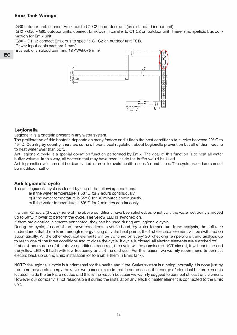
G30 outdoor unit: connect Emix bus to C1 C2 on outdoor unit (as a standard indoor unit) G42 - G50 – G65 outdoor units: connect Emix bus in parallel to C1 C2 on outdoor unit. There is no speficic bus con-nection for Emix unit. G80 – G110: connect Emix bus to specific C1 C2 on outdoor unit PCB. Power input cable section: 4 mm2 Bus cable: shielded pair min. 18 AWG/075 mm2
Emix Tank Wirings
LegionellaLegionella is a bacteria present in any water system.The proliferation of this bacteria depends on many factors and it finds the best conditions to survive between 20º C to 45º C. Country by country, there are some different local regulation about Legionella prevention but all of them require to heat water over than 50ºC.Anti legionella cycle is a special operation function performed by Emix. The goal of this function is to heat all water buffer volume. In this way, all bacteria that may have been inside the buffer would be killed.Anti legionella cycle can not be deactivated in order to avoid health issues for end users. The cycle procedure can not be modified, neither.
Anti legionella cycleThe anti legionella cycle is closed by one of the following conditions: a) if the water temperature is 50º C for 2 hours continuously. b) if the water temperature is 55º C for 30 minutes continuously. c) if the water temperature is 60º C for 2 minutes continuously.
If within 72 hours (3 days) none of the above conditions have bee satisfied, automatically the water set point is moved up to 60ºC if lower to perform the cycle. The yellow LED is switched on.If there are electrical elements connected, they can be used during anti legionella cycle.During the cycle, if none of the above conditions is verified and, by water temperature trend analysis, the software understands that there is not enough energy using only the heat pump, the first electrical element will be switched on automatically. All the other electrical elements will be switched on every120’ checking temperature trend analysis up to reach one of the three conditions and to close the cycle. If cycle is closed, all electric elements are switched off.Ifafter4hoursnoneoftheaboveconditionsoccurred,thecyclewillbeconsideredNOTclosed,itwillcontinueandtheyellowLEDwillflashwithlowfrequencytoalerttheenduser.Forthisreason,wewarmlyrecommendtoconnectelectric back up during Emix installation (or to enable them in Emix tank).
NOTE:thelegionellacycleisfundamentalforthehealthandiftheiSeriessystemisrunning,normallyitisdonejustbythethermodynamicenergy;howeverwecannotexcludethatinsomecasestheenergyofelectricalheaterelementslocated inside the tank are needed and this is the reason because we warmly suggest to connect at least one element. HoweverourcompanyisnotresponsibleifduringtheinstallationanyelectricheaterelementisconnectedtotheEmixunit.
15
EG
Electric back up management – Booster mode
By pressing operation button until the blue led is blinking, end users can activate the booster mode. In this case the software will manage the electric heaters under certain conditions.If after 120’ from the start up of the system (time counter does not start when the automatic mode is set but when the heat pump is switched on), water set point is not reached, the first electrical element will be activated automatically. The other steps, one by one, will be turned on every 120’ following water temperature trend, up to reach set point.To exit the booster mode, it’s necessary to repeat the starting procedure.
Electric back up management – Super Booster mode
By pressing operation button until yellow led is turned on (3 beeps will be listened when the button will be released), end user can activate the super booster mode. In this case all electric elements connected are switched on in one shot, together with the heat pump. When water set point is reached, all heaters are switched off. To exit super booster mode, it’s necessary to repeat the starting procedure.This option is very useful when it’s necessary to heat the water as soon as possible.
Electric back up management – Automatic modes
Emix tank software can automatically manage electric back up heaters under certain conditions. This mean that these operation modes are not to be set and that can not be deactivated.They are:- Antifreeze mode- Cold draft prevention- Electric water heater mode
Electric back up management – Antifreeze mode
If water temperature inside the buffer tank is lower than 10° C, all electric elements connected are switched on. When the water temperature reaches 11° C all the elements are turned off.
Electric back up management – Cold draft prevention
If water temperature is lower than 40º C and one or more indoor units is in cold draft condition, one by one electrical element are switched on per time (every 10’) and switched off all together when water temperature reaches 50º C and no cold draft condition on any indoor unit is detected.
Electric back up management – Electric water heater
If the outdoor unit is stopped for maintenance of end user’s decision (no communication), Emix tank unit could be used as controller of the electrical heater elements located inside the tank, exactly like any electric water heater. In this case, if the water temperature is lower than the desired temperature for more than 30’, all the connected electrical heaters will switch on up to the reaching of the setpoint. End users can switch off Emix tank if they do not want to have this option.
16
EG
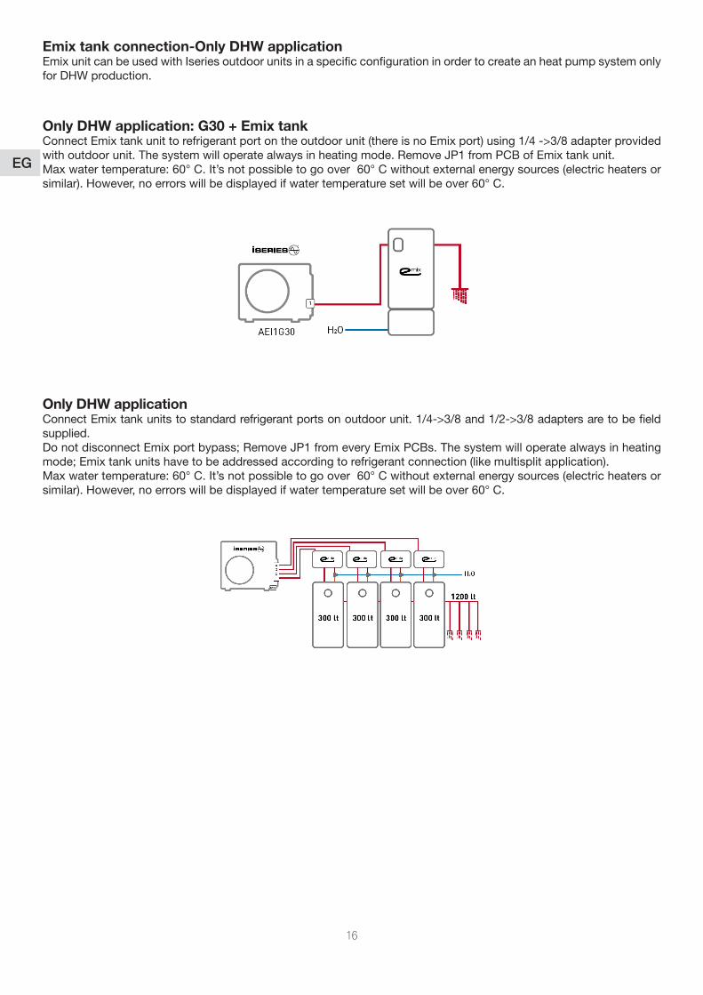
Emix tank connection-Only DHW application Emix unit can be used with Iseries outdoor units in a specific configuration in order to create an heat pump system only forDHWproduction.
Only DHW application: G30 + Emix tankConnect Emix tank unit to refrigerant port on the outdoor unit (there is no Emix port) using 1/4 ->3/8 adapter provided with outdoor unit. The system will operate always in heating mode. Remove JP1 from PCB of Emix tank unit.Max water temperature: 60° C. It’s not possible to go over 60° C without external energy sources (electric heaters or similar).However,noerrorswillbedisplayedifwatertemperaturesetwillbeover60°C.
Only DHW applicationConnect Emix tank units to standard refrigerant ports on outdoor unit. 1/4->3/8 and 1/2->3/8 adapters are to be field supplied.DonotdisconnectEmixportbypass;RemoveJP1fromeveryEmixPCBs.Thesystemwilloperatealwaysinheatingmode;Emixtankunitshavetobeaddressedaccordingtorefrigerantconnection(likemultisplitapplication).Max water temperature: 60° C. It’s not possible to go over 60° C without external energy sources (electric heaters or similar).However,noerrorswillbedisplayedifwatertemperaturesetwillbeover60°C.
17
EG
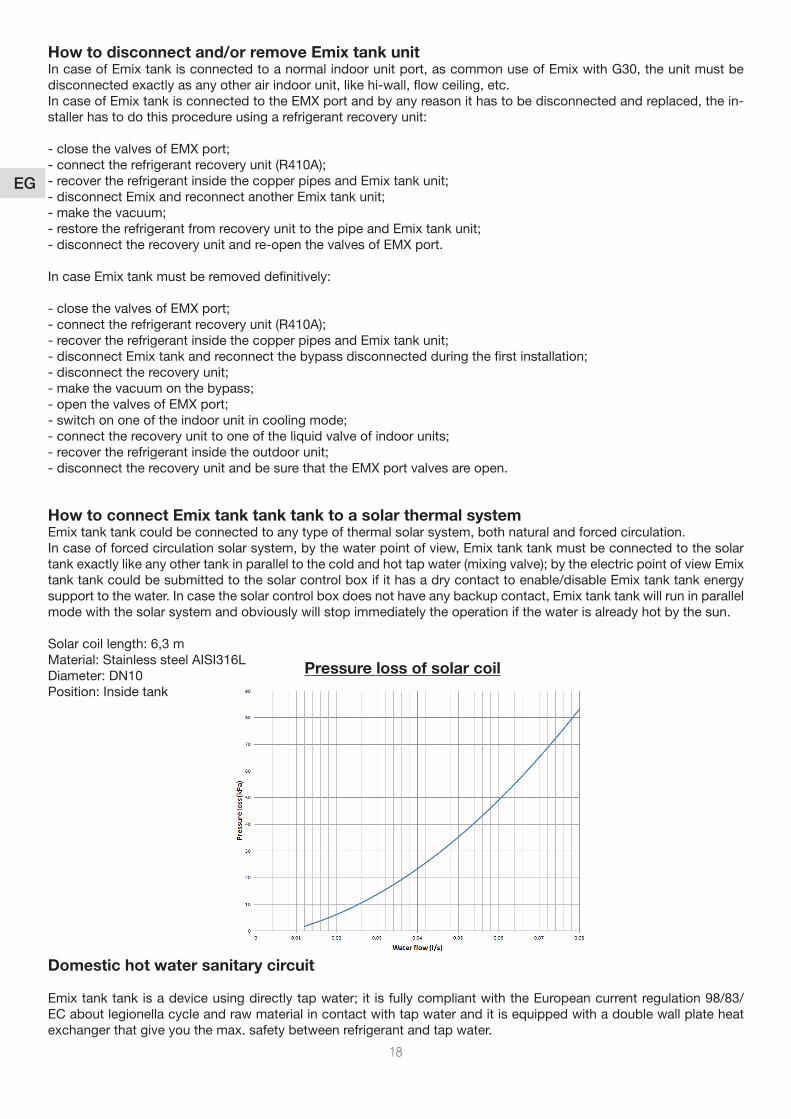
OPERATION CONTROL PANEL Unit is turned on/off by pressing the control button for 5 seconds.
How to use Emix Tank in electric boiler mode
Firstofallyouhavetoswitchontheunitbythemainswitch
A = automatic mode of operation to be used normally when the Emix tank is connected to the iSeries0 = off modeR = electric water heater manually controlled by thermostat (to be used if the iSeries is in maintenance)
Control PanelHerethefrontuserpanel
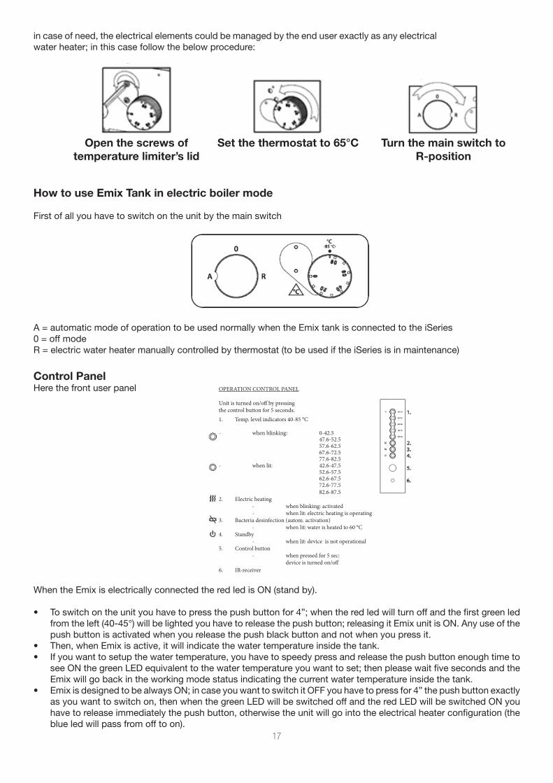
in case of need, the electrical elements could be managed by the end user exactly as any electrical waterheater;inthiscasefollowthebelowprocedure:
Turn the main switch to R-position
Set the thermostat to 65°COpen the screws of temperature limiter’s lid
WhentheEmixiselectricallyconnectedtheredledisON(standby).
• Toswitchontheunityouhavetopressthepushbuttonfor4”;whentheredledwillturnoffandthefirstgreenled fromtheleft(40-45°)willbelightedyouhavetoreleasethepushbutton;releasingitEmixunitisON.Anyuseofthe push button is activated when you release the push black button and not when you press it.
• Then, when Emix is active, it will indicate the water temperature inside the tank.• If you want to setup the water temperature, you have to speedy press and release the push button enough time to
seeONthegreenLEDequivalenttothewatertemperatureyouwanttoset;thenpleasewaitfivesecondsandthe Emix will go back in the working mode status indicating the current water temperature inside the tank.
• EmixisdesignedtobealwaysON;incaseyouwanttoswitchitOFFyouhavetopressfor4”thepushbuttonexactly asyouwanttoswitchon,thenwhenthegreenLEDwillbeswitchedoffandtheredLEDwillbeswitchedONyou have to release immediately the push button, otherwise the unit will go into the electrical heater configuration (the blue led will pass from off to on).
1. Temp. level indicators 40-85 °C
- when blinking: 0-42.5 47.6-52.5 57.6-62.5 67.6-72.5 77.6-82.5 - when lit: 42.6-47.5 52.6-57.5 62.6-67.5 72.6-77.5 82.6-87.52. Electric heating - when blinking: activated - when lit: electric heating is operating3. Bacteria desinfection (autom. activation) - when lit: water is heated to 60 °C4. Standby - when lit: device is not operational5. Control button - when pressed for 5 sec: device is turned on/off6. IR-receiver
18
EG
How to disconnect and/or remove Emix tank unitIn case of Emix tank is connected to a normal indoor unit port, as common use of Emix with G30, the unit must be disconnected exactly as any other air indoor unit, like hi-wall, flow ceiling, etc.In case of Emix tank is connected to the EMX port and by any reason it has to be disconnected and replaced, the in-staller has to do this procedure using a refrigerant recovery unit:
-closethevalvesofEMXport;-connecttherefrigerantrecoveryunit(R410A);-recovertherefrigerantinsidethecopperpipesandEmixtankunit;-disconnectEmixandreconnectanotherEmixtankunit;-makethevacuum;-restoretherefrigerantfromrecoveryunittothepipeandEmixtankunit;- disconnect the recovery unit and re-open the valves of EMX port.
In case Emix tank must be removed definitively:
-closethevalvesofEMXport;-connecttherefrigerantrecoveryunit(R410A);-recovertherefrigerantinsidethecopperpipesandEmixtankunit;-disconnectEmixtankandreconnectthebypassdisconnectedduringthefirstinstallation;-disconnecttherecoveryunit;-makethevacuumonthebypass;-openthevalvesofEMXport;-switchononeoftheindoorunitincoolingmode;-connecttherecoveryunittooneoftheliquidvalveofindoorunits;-recovertherefrigerantinsidetheoutdoorunit;- disconnect the recovery unit and be sure that the EMX port valves are open.
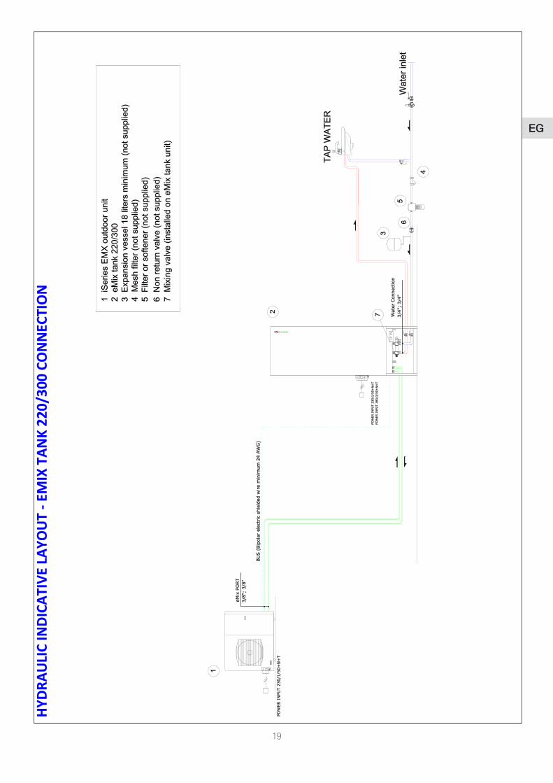
How to connect Emix tank tank tank to a solar thermal systemEmix tank tank could be connected to any type of thermal solar system, both natural and forced circulation.In case of forced circulation solar system, by the water point of view, Emix tank tank must be connected to the solar tankexactlylikeanyothertankinparalleltothecoldandhottapwater(mixingvalve);bytheelectricpointofviewEmixtank tank could be submitted to the solar control box if it has a dry contact to enable/disable Emix tank tank energy support to the water. In case the solar control box does not have any backup contact, Emix tank tank will run in parallel mode with the solar system and obviously will stop immediately the operation if the water is already hot by the sun.
Solar coil length: 6,3 mMaterial: Stainless steel AISI316LDiameter: DN10Position: Inside tank
Domestic hot water sanitary circuit
Emixtanktankisadeviceusingdirectlytapwater;it isfullycompliantwiththeEuropeancurrentregulation98/83/EC about legionella cycle and raw material in contact with tap water and it is equipped with a double wall plate heat exchanger that give you the max. safety between refrigerant and tap water.
Pressure loss of solar coil
19
EG
20
EG
21
EG
22
EG

Via Varese, 90 - 21013 Gallarate - Va - Italy
Tel. +39 0331 755111 - Fax +39 0331 776240
www.argoclima.com

Via Varese, 90 - 21013 Gallarate - Va - Italy
Tel. +39 0331 755111 - Fax +39 0331 776240
www.argoclima.com


![[es] Instrucciones de uso 3 [pt] Instruções de serviço · 2012-12-08 · superior del recipiente, que por lo general es mayor que el diámetro de la base del recipiente. Utilizar](https://static.fdocument.org/doc/165x107/5eaedec814e2405fe4385954/es-instrucciones-de-uso-3-pt-instrues-de-servio-2012-12-08-superior.jpg)
