Ohm’s Law & Resistors - UTSAphysics.utsa.edu/PhysicsLabs/1971/67 Ohm's Law -v3 capstone.pdf ·...
11
012-09285 Physics Experiment Manual 67 Ohm’s Law PASCO-Benson © 2013 67 - 1 of 11 Ohm’s Law & Resistors Equipment List Qty Items Part Numbers 1 PASCO 750 Interface 1 AC/DC Electronics Lab EM-8656 2 Banana Plug Patch Cord SE-9750 or SE-9751 1 10 Ω(Brown Black Black), 1 lightbulb 1 Voltage Sensor CI-6503 1 Current Sensor CI-6556 1 1000 Ω (Brown Black Red) 2 100 Ω (Brown Black Brown), Introduction The purpose of this activity is to confirm the relationship of current, voltage, and resistance in an electric circuit using a one resistor circuit. You will also explore what happens to the resistance of a light bulb’s filament as it changes temperature. Next you will determine what happens to resistors as they are added in parallel and series. Use the Capstone software to measure the current through individual resistors and the filament of a light bulb as the voltage across the resistors and the filament of the light bulb is changed and current sensor to measure the current through the circuits. Background Ohm discovered that when the voltage (potential difference) across a resistor changes, the current through the resistor changes. He expressed this as = = 1 Equation 1 where I is current, V is voltage (potential difference), and R is resistance. Current is directly proportional to voltage and inversely proportional to resistance. In other words, as the voltage increases, so does the current. The proportionality constant is the value of the resistance. Since the current is inversely proportional to the resistance, as the resistance increases, the current decreases. A resistor is ‘Ohmic’ if as voltage across the resistor is increased, a graph of voltage versus current shows a straight line (indicating a constant resistance). The slope of the line is the value of the resistance. A resistor is ‘non-Ohmic’ if the graph of voltage versus current is not a straight line. For example, if resistance changes as voltage changes, the graph of voltage versus current might show a curve with a changing slope. For a certain resistor, the value of its resistance does not change appreciably. However, for a light bulb, the resistance of the filament will change as it heats up and cools down. At high AC frequencies, the filament doesn’t have time to cool down, so it remains at a nearly constant temperature and the resistance stays relatively constant. At low AC frequencies (e.g., less than one hertz), the filament has time to change temperature. As a consequence, the resistance of the
Transcript of Ohm’s Law & Resistors - UTSAphysics.utsa.edu/PhysicsLabs/1971/67 Ohm's Law -v3 capstone.pdf ·...
012-09285 Physics Experiment Manual 67 Ohm’s Law
PASCO-Benson © 2013 67 - 1 of 11
Ohm’s Law & Resistors
Equipment List
Qty Items Part Numbers
1 PASCO 750 Interface
1 AC/DC Electronics Lab EM-8656
2 Banana Plug Patch Cord SE-9750 or SE-9751
1 10 Ω(Brown Black Black), 1 lightbulb
1 Voltage Sensor CI-6503
1 Current Sensor CI-6556
1 1000 Ω (Brown Black Red)
2 100 Ω (Brown Black Brown),
Introduction
The purpose of this activity is to confirm the relationship of current, voltage, and resistance in an
electric circuit using a one resistor circuit. You will also explore what happens to the resistance
of a light bulb’s filament as it changes temperature. Next you will determine what happens to
resistors as they are added in parallel and series. Use the Capstone software to measure the
current through individual resistors and the filament of a light bulb as the voltage across the
resistors and the filament of the light bulb is changed and current sensor to measure the current
through the circuits.
Background
Ohm discovered that when the voltage (potential difference) across a resistor changes, the
current through the resistor changes. He expressed this as
𝑉 = 𝐼𝑅 𝑜𝑟 𝐼 = 𝑉1
𝑅 Equation 1
where I is current, V is voltage (potential difference), and R is resistance. Current is directly
proportional to voltage and inversely proportional to resistance. In other words, as the voltage
increases, so does the current. The proportionality constant is the value of the resistance. Since
the current is inversely proportional to the resistance, as the resistance increases, the current
decreases.
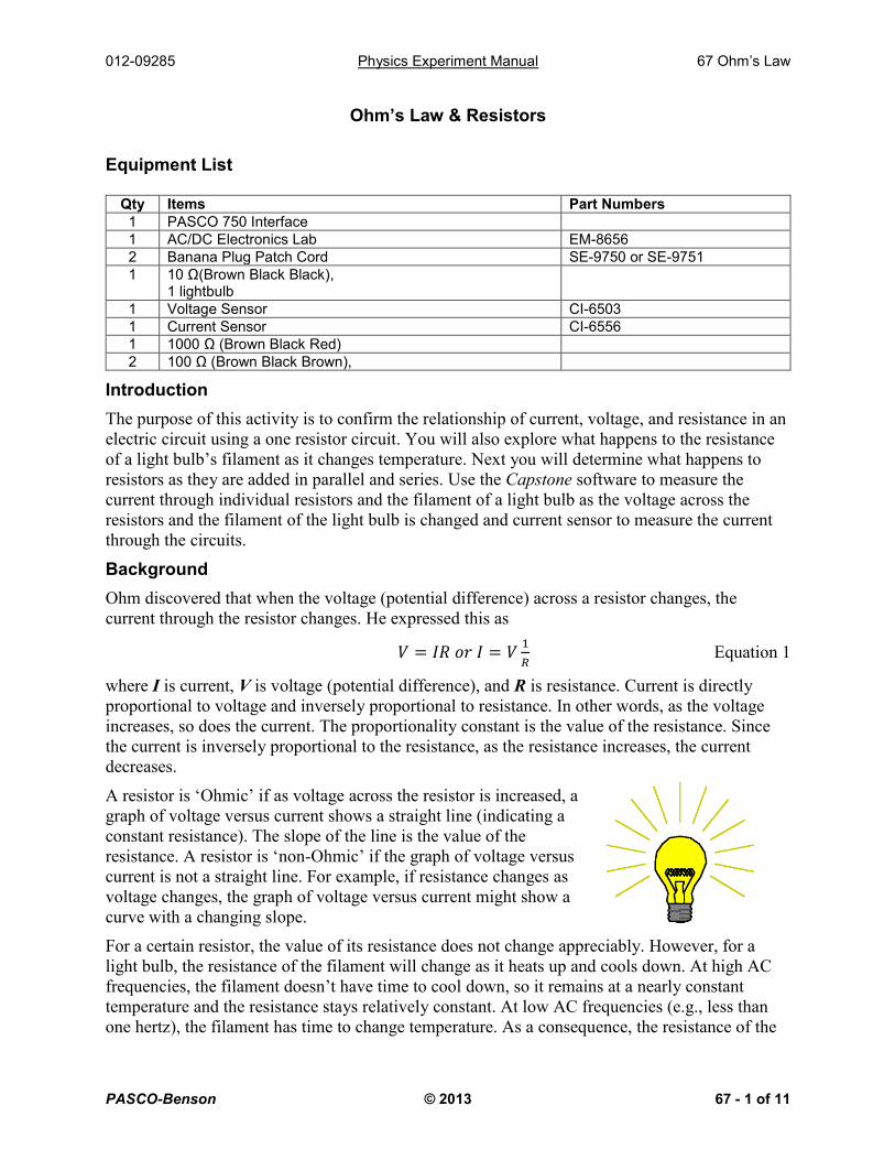
A resistor is ‘Ohmic’ if as voltage across the resistor is increased, a
graph of voltage versus current shows a straight line (indicating a
constant resistance). The slope of the line is the value of the
resistance. A resistor is ‘non-Ohmic’ if the graph of voltage versus
current is not a straight line. For example, if resistance changes as
voltage changes, the graph of voltage versus current might show a
curve with a changing slope.
For a certain resistor, the value of its resistance does not change appreciably. However, for a
light bulb, the resistance of the filament will change as it heats up and cools down. At high AC
frequencies, the filament doesn’t have time to cool down, so it remains at a nearly constant
temperature and the resistance stays relatively constant. At low AC frequencies (e.g., less than
one hertz), the filament has time to change temperature. As a consequence, the resistance of the
012-09285 Physics Experiment Manual 67 Ohm’s Law
PASCO-Benson © 2013 67 - 2 of 11
filament changes dramatically and the resulting change in current through the filament is
interesting to watch.
In the first part of this activity, investigate the relationship
between current and voltage in simple ten-ohm (Ω) and one-
hundred ohm resistors. Then you will investigate the
relationship between current and voltage in the filament of a
small light bulb.
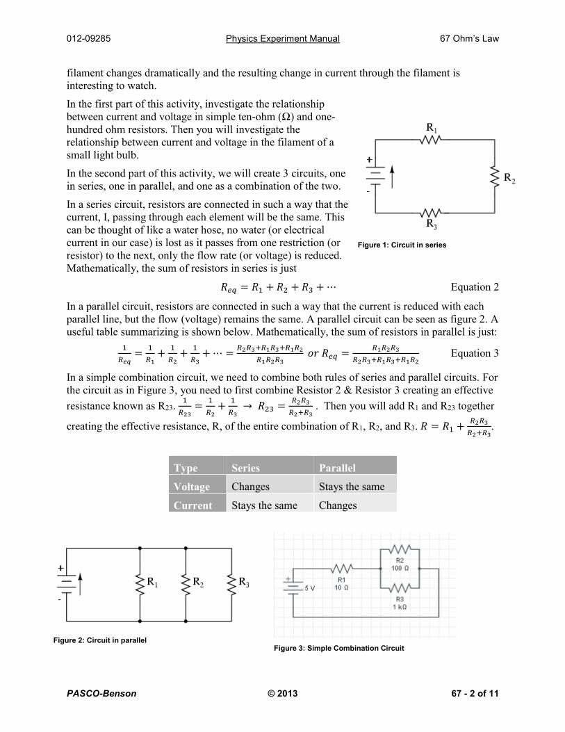
In the second part of this activity, we will create 3 circuits, one
in series, one in parallel, and one as a combination of the two.
In a series circuit, resistors are connected in such a way that the
current, I, passing through each element will be the same. This
can be thought of like a water hose, no water (or electrical
current in our case) is lost as it passes from one restriction (or
resistor) to the next, only the flow rate (or voltage) is reduced.
Mathematically, the sum of resistors in series is just
𝑅𝑒𝑞 = 𝑅1 + 𝑅2 + 𝑅3 + ⋯ Equation 2
In a parallel circuit, resistors are connected in such a way that the current is reduced with each
parallel line, but the flow (voltage) remains the same. A parallel circuit can be seen as figure 2. A
useful table summarizing is shown below. Mathematically, the sum of resistors in parallel is just:
1
𝑅𝑒𝑞=
1
𝑅1+
1
𝑅2+
1
𝑅3+ ⋯ =
𝑅2𝑅3+𝑅1𝑅3+𝑅1𝑅2
𝑅1𝑅2𝑅3 𝑜𝑟 𝑅𝑒𝑞 =
𝑅1𝑅2𝑅3
𝑅2𝑅3+𝑅1𝑅3+𝑅1𝑅2 Equation 3
In a simple combination circuit, we need to combine both rules of series and parallel circuits. For
the circuit as in Figure 3, you need to first combine Resistor 2 & Resistor 3 creating an effective
resistance known as R23. 1
𝑅23=
1
𝑅2+
1
𝑅3 → 𝑅23 =
𝑅2𝑅3
𝑅2+𝑅3 . Then you will add R1 and R23 together
creating the effective resistance, R, of the entire combination of R1, R2, and R3. 𝑅 = 𝑅1 +𝑅2𝑅3
𝑅2+𝑅3.
Type Series Parallel
Voltage Changes Stays the same
Current Stays the same Changes
Figure 1: Circuit in series
Figure 2: Circuit in parallel Figure 3: Simple Combination Circuit
012-09285 Physics Experiment Manual 67 Ohm’s Law
PASCO-Benson © 2013 67 - 3 of 11
The rules for using a multimeter (and similar):
1. To measure current through a resistor, the multimeter (set as an AMPMETER) is
connected “in series” with R.
2. To measure the voltage drop across a resistor, the multimeter (set as VOLTMETER) is
connected “in parallel” with R.
3. To measure a resistance, the multimeter, set as an OHMMETER, is connected in
parallel with the resistor while NO current flow through the resistor (open-circuit).
SAFETY REMINDER
Be sure to have carefully read the rules for using a multimeter and how to connect your instrument properly to read current and voltage.
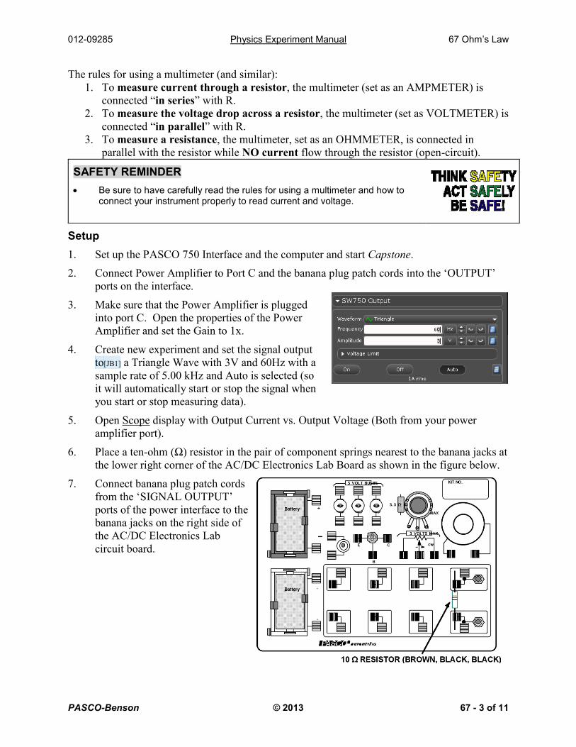
Setup
1. Set up the PASCO 750 Interface and the computer and start Capstone.
2. Connect Power Amplifier to Port C and the banana plug patch cords into the ‘OUTPUT’
ports on the interface.
3. Make sure that the Power Amplifier is plugged
into port C. Open the properties of the Power
Amplifier and set the Gain to 1x.
4. Create new experiment and set the signal output
to[JB1] a Triangle Wave with 3V and 60Hz with a
sample rate of 5.00 kHz and Auto is selected (so
it will automatically start or stop the signal when
you start or stop measuring data).
5. Open Scope display with Output Current vs. Output Voltage (Both from your power
amplifier port).
6. Place a ten-ohm (Ω) resistor in the pair of component springs nearest to the banana jacks at
the lower right corner of the AC/DC Electronics Lab Board as shown in the figure below.
7. Connect banana plug patch cords
from the ‘SIGNAL OUTPUT’
ports of the power interface to the
banana jacks on the right side of
the AC/DC Electronics Lab
circuit board.
012-09285 Physics Experiment Manual 67 Ohm’s Law
PASCO-Benson © 2013 67 - 4 of 11
Procedure 1 – Measure Resistance
Measure voltage and current for resistors
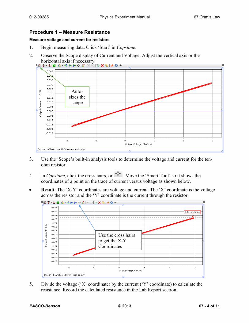
1. Begin measuring data. Click ‘Start’ in Capstone.
2. Observe the Scope display of Current and Voltage. Adjust the vertical axis or the
horizontal axis if necessary.
3. Use the ‘Scope’s built-in analysis tools to determine the voltage and current for the ten-
ohm resistor.
4. In Capstone, click the cross hairs, or . Move the ‘Smart Tool’ so it shows the
coordinates of a point on the trace of current versus voltage as shown below.
Result: The ‘X-Y’ coordinates are voltage and current. The ‘X’ coordinate is the voltage
across the resistor and the ‘Y’ coordinate is the current through the resistor.
5. Divide the voltage (‘X’ coordinate) by the current (‘Y’ coordinate) to calculate the
resistance. Record the calculated resistance in the Lab Report section.
Use the cross hairs
to get the X-Y
Coordinates
Auto-
sizes the
scope
012-09285 Physics Experiment Manual 67 Ohm’s Law
PASCO-Benson © 2013 67 - 5 of 11
6. Click ‘Stop’ to end data measurement.
7. Replace the ten-ohm resistor with a 100-ohm resistor and repeat the procedure.
8. Record the calculated resistance in the Lab Report.
Procedure 2 – Light Bulb
Measure voltage and current for a light-bulb filament
1. After you record your data for the resistors, click ‘Stop’ to end data measurement.
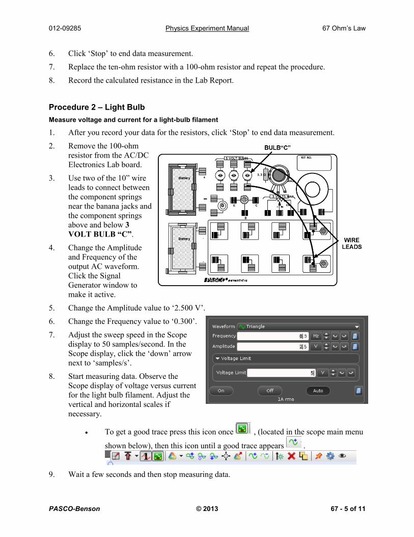
2. Remove the 100-ohm
resistor from the AC/DC
Electronics Lab board.
3. Use two of the 10” wire
leads to connect between
the component springs
near the banana jacks and
the component springs
above and below 3
VOLT BULB “C”.
4. Change the Amplitude
and Frequency of the
output AC waveform.
Click the Signal
Generator window to
make it active.
5. Change the Amplitude value to ‘2.500 V’.
6. Change the Frequency value to ‘0.300’.
7. Adjust the sweep speed in the Scope
display to 50 samples/second. In the
Scope display, click the ‘down’ arrow
next to ‘samples/s’.
8. Start measuring data. Observe the
Scope display of voltage versus current
for the light bulb filament. Adjust the
vertical and horizontal scales if
necessary.
To get a good trace press this icon once , (located in the scope main menu
shown below), then this icon until a good trace appears .
9. Wait a few seconds and then stop measuring data.

012-09285 Physics Experiment Manual 67 Ohm’s Law
PASCO-Benson © 2013 67 - 6 of 11
10. Use the built-in analysis tools in the Scope display to find the coordinates at several points
on the trace of voltage versus current. Calculate the ratio of voltage to current at each
point.
11. Make a sketch of the Scope display screen for voltage and current of the light bulb filament
in the Lab Report section.
Procedure 3 – Series Circuit
1. Connect the voltage sensor to port A and the current sensor to port B.
2. Connect the Power Amplifier to port C and set it to 5V DC voltage.
3. Please let your R1 = 10Ω, R2 = 100Ω, R3= 1000Ω and assemble as shown in the image
below. The red and black wires go to the power amplifier and begin recording.
IMPORTANT: If there is a red light on the Power Amplifier, disconnect the power
immediately from the circuit. Contact your TA to look over the circuit and address the
problem.
4. First measure the voltage. This can be done by
taking the voltage probes and placing each one across (in parallel with) the resistor. Measure
the voltage for R1, R2, & R3 and record your results in the table.
5. Next measure the current. Lift one end of a resistor up keeping the other end in the spring.
With the end that is not in the spring, alligator clip one end of the current sensor to the
resistor and touch the other end of the current sensor to the spring, there is no need to
alligator clip it to the spring.
An example of this can be
seen below. Measure the
current for R1, R2, & R3 and
record your results in the
table.
012-09285 Physics Experiment Manual 67 Ohm’s Law
PASCO-Benson © 2013 67 - 7 of 11
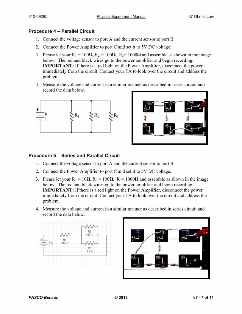
Procedure 4 – Parallel Circuit
1. Connect the voltage sensor to port A and the current sensor to port B.
2. Connect the Power Amplifier to port C and set it to 5V DC voltage.
3. Please let your R1 = 100Ω, R2 = 100Ω, R3= 1000Ω and assemble as shown in the image
below. The red and black wires go to the power amplifier and begin recording.
IMPORTANT: If there is a red light on the Power Amplifier, disconnect the power
immediately from the circuit. Contact your TA to look over the circuit and address the
problem.
4. Measure the voltage and current in a similar manner as described in series circuit and
record the data below.
Procedure 5 – Series and Parallel Circuit
1. Connect the voltage sensor to port A and the current sensor to port B.
2. Connect the Power Amplifier to port C and set it to 5V DC voltage.
3. Please let your R1 = 10Ω, R2 = 100Ω, R3= 1000Ω and assemble as shown in the image
below. The red and black wires go to the power amplifier and begin recording.
IMPORTANT: If there is a red light on the Power Amplifier, disconnect the power
immediately from the circuit. Contact your TA to look over the circuit and address the
problem.
4. Measure the voltage and current in a similar manner as described in series circuit and
record the data below.
012-09285 Physics Experiment Manual 67 Ohm’s Law
PASCO-Benson © 2013 67 - 8 of 11
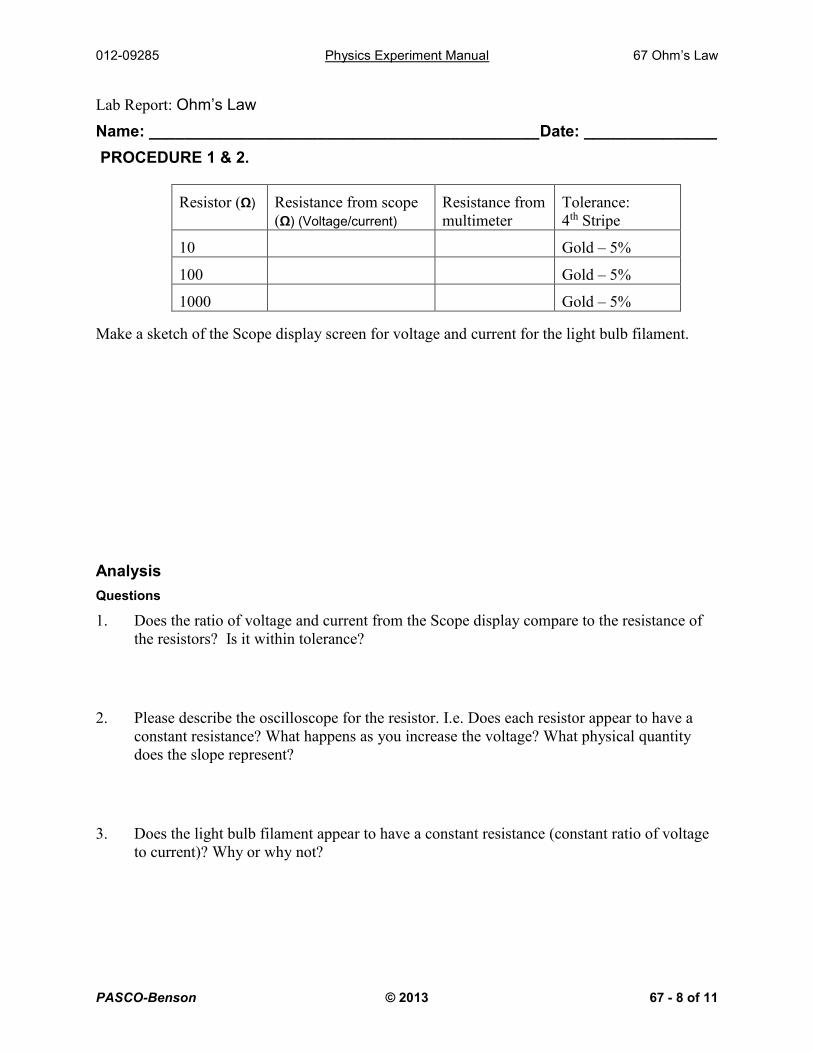
Lab Report: Ohm’s Law
Name: ____________________________________________Date: _______________
PROCEDURE 1 & 2.
Make a sketch of the Scope display screen for voltage and current for the light bulb filament.
Analysis
Questions
1. Does the ratio of voltage and current from the Scope display compare to the resistance of
the resistors? Is it within tolerance?
2. Please describe the oscilloscope for the resistor. I.e. Does each resistor appear to have a
constant resistance? What happens as you increase the voltage? What physical quantity
does the slope represent?
3. Does the light bulb filament appear to have a constant resistance (constant ratio of voltage
to current)? Why or why not?
Resistor (Ω) Resistance from scope
(Ω) (Voltage/current)
Resistance from
multimeter
Tolerance:
4th Stripe
10 Gold – 5%
100 Gold – 5%
1000 Gold – 5%
012-09285 Physics Experiment Manual 67 Ohm’s Law
PASCO-Benson © 2013 67 - 9 of 11
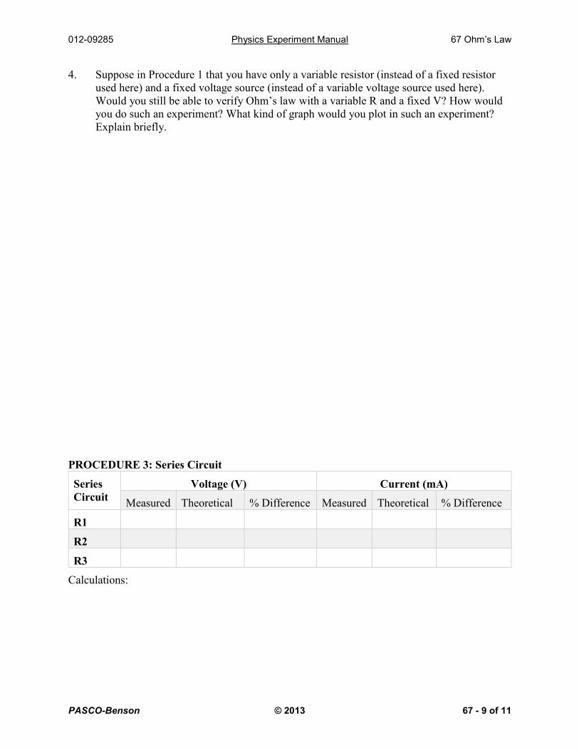
4. Suppose in Procedure 1 that you have only a variable resistor (instead of a fixed resistor
used here) and a fixed voltage source (instead of a variable voltage source used here).
Would you still be able to verify Ohm’s law with a variable R and a fixed V? How would
you do such an experiment? What kind of graph would you plot in such an experiment?
Explain briefly.
PROCEDURE 3: Series Circuit
Series
Circuit
Voltage (V) Current (mA)
Measured Theoretical % Difference Measured Theoretical % Difference
R1
R2
R3
Calculations:
012-09285 Physics Experiment Manual 67 Ohm’s Law
PASCO-Benson © 2013 67 - 10 of 11
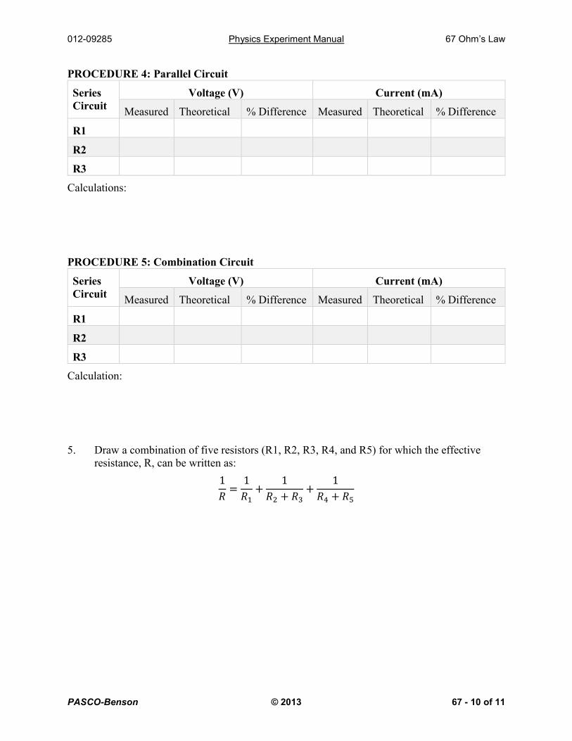
PROCEDURE 4: Parallel Circuit
Series
Circuit
Voltage (V) Current (mA)
Measured Theoretical % Difference Measured Theoretical % Difference
R1
R2
R3
Calculations:
PROCEDURE 5: Combination Circuit
Series
Circuit
Voltage (V) Current (mA)
Measured Theoretical % Difference Measured Theoretical % Difference
R1
R2
R3
Calculation:
5. Draw a combination of five resistors (R1, R2, R3, R4, and R5) for which the effective
resistance, R, can be written as:
1
𝑅=
1
𝑅1+
1
𝑅2 + 𝑅3+
1
𝑅4 + 𝑅5
012-09285 Physics Experiment Manual 67 Ohm’s Law
PASCO-Benson © 2013 67 - 11 of 11
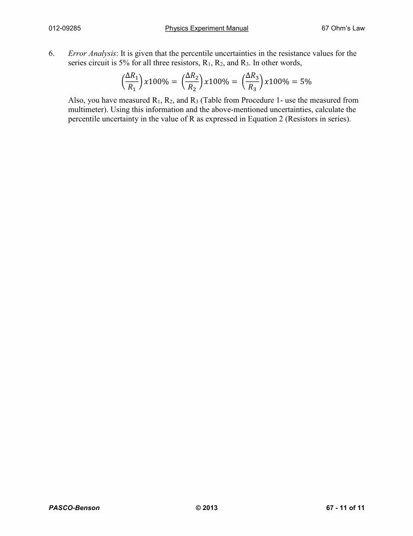
6. Error Analysis: It is given that the percentile uncertainties in the resistance values for the
series circuit is 5% for all three resistors, R1, R2, and R3. In other words,
(∆𝑅1
𝑅1) 𝑥100% = (
∆𝑅2
𝑅2) 𝑥100% = (
∆𝑅3
𝑅3) 𝑥100% = 5%
Also, you have measured R1, R2, and R3 (Table from Procedure 1- use the measured from
multimeter). Using this information and the above-mentioned uncertainties, calculate the
percentile uncertainty in the value of R as expressed in Equation 2 (Resistors in series).