ΔΙΗΜΕΡΙΔΑ ΟΙ ΣΗΡΑΓΓΕΣ ΤΗΣ ΕΓΝΑΤΙΑΣ ΟΔΟΥ · This is especially...
18
ΔΙΗΜΕΡΙΔΑ "ΟΙ ΣΗΡΑΓΓΕΣ ΤΗΣ ΕΓΝΑΤΙΑΣ ΟΔΟΥ" TUNNELLING IN DIFFICULT GROUND Εισηγητές : Dr. GUNTER RIEDMULLER Dr. WULF SCHUBERT Ιωάννινα, 15-16/10/99 "ΕΓΝΑΤΙΑ ΟΔΟΣ Α.Ε." & Ε.Ε.Σ.Υ.Ε.
Transcript of ΔΙΗΜΕΡΙΔΑ ΟΙ ΣΗΡΑΓΓΕΣ ΤΗΣ ΕΓΝΑΤΙΑΣ ΟΔΟΥ · This is especially...
ΔΙΗΜΕΡΙΔΑ
"ΟΙ ΣΗΡΑΓΓΕΣ ΤΗΣ ΕΓΝΑΤΙΑΣ ΟΔΟΥ"
TUNNELLING IN DIFFICULT GROUND
Εισηγητές : Dr. GUNTER RIEDMULLER
Dr. WULF SCHUBERT
Ιωάννινα, 15-16/10/99 "ΕΓΝΑΤΙΑ ΟΔΟΣ Α.Ε."
& Ε.Ε.Σ.Υ.Ε.
Tunnelling in Difficult Ground
Διημερίδα "ΟΙ ΣΗΡΑΓΓΕΣ ΤΗΣ ΕΓΝΑΤΙΑΣ ΟΔΟΥ" «ΕΓΝΑΤΙΑ ΟΔΟΣ Α.Ε.» & Ε.Ε.Σ.Υ.Ε. Εισηγητής : Dr. G. RIEDMULLER Σελίδα 2 από 18 15-16 Οκτωβρίου 1999 Dr. W. SCHUBERT
TUNNELLING IN DIFFICULT GROUND ABSTRACT
Difficult ground is mainly related to brittle faulting. The geotechnical significance of faults is frequently misunderstood concerning their extreme heterogeneity in terms of rock mass strength, primary stress conditions and groundwater.
In this lecture we will characterize brittle faults from the geotechnical point of view and
we will present methods of investigation and construction of tunnels in difficult ground. Difficult ground requires special considerations during all phases of a tunnel project.
Important tasks during the design process are the evaluation of the route corridor, the geotechnical investigation, the alignment selection, selection of construction method, the preliminary and final design, as well as the contract setup, allowing a certain flexibility during construction. During construction continuous data collection and evaluation, as well as monitoring allows an update of the geological model and the rock mass behavior. Based on the updated model, excavation and support can be adjusted to the actual conditions, preconditions for safe and economical tunneling.
As even the best quality in construction cannot compensate mistakes during
investigation and design, the importance of this part of a project is emphasised. Case histories demonstrate the possibilities of investigation and design with the help of advanced tools.
Success during construction of tunnels in difficult ground depends to a great extent on
the quality of the geotechnical engineers involved in construction. For continuous recording and evaluation of all relevant data, a data base system has been developed. It allows the geotechnical engineer to observe trends and to correlate various factors. In combination with methods, recently developed to interpret the results of absolute displacement monitoring in terms of displacement vectors, the capability for short term prediction during construction has been increased remarkably. This is especially important for heterogeneous rock masses which require frequent changes in excavation and support. For example, for squeezing ground special support measures, called “Lining Stress Controllers” have been developed by our group.
The problems related to tunnelling in difficult ground will be demonstrated by case
studies from the Austrian Alps and Greece.
Tunnelling in Difficult Ground
Διημερίδα "ΟΙ ΣΗΡΑΓΓΕΣ ΤΗΣ ΕΓΝΑΤΙΑΣ ΟΔΟΥ" «ΕΓΝΑΤΙΑ ΟΔΟΣ Α.Ε.» & Ε.Ε.Σ.Υ.Ε. Εισηγητής : Dr. G. RIEDMULLER Σελίδα 3 από 18 15-16 Οκτωβρίου 1999 Dr. W. SCHUBERT
1. INTRODUCTION
When planning tunnels in difficult geological conditions a very considerate approach is required in order to allow smooth construction without cost and time overruns, and technical surprises. This care has to start with the preliminary planning, route selection, selection of construction method, as well as contract set-up and selection of contractor, and to continue during construction, by providing experienced personnel for construction, supervision, monitoring, and site management.
Many geotechnical problems arise when tunnelling through fault zones. Faults are
complex zones, ranging from decimetres to kilometres wide, in which shear deformation is intense. Fault zones in the upper 5 to 10 kilometres of the Earth’s crust, the so called brittle faults, consist of an anastomosing complex of shear fractures (1,2,3). Brittle fault zones are highly heterogeneous, consisting of fractured, brecciated rocks separated by fine-grained fault gouges. Low-temperature solution transfer contributes to the alteration of the faulted rocks through transformation and neoformation of clay minerals (4,5,6). A regular pattern of shear and tensile fractures develops in these zones, reflecting the geometry of the strain field and, consequently, the orientation of the principal stresses. Slickensides with striations indicate the most recent tectonic slips and relative movements.
A characteristic phenomenon of brittle fault zones is the random occurrence of units of
more or less unaltered, undeformed rock, called ”knockers” or ”horses” (7). These mainly lenticular units of rock mass develop in different dimensions and can reach magnitudes of up to several hundreds of metres. These units are surrounded by fine-grained gouge material, which appears to be flowing around the ”horses” in an anastomosing pattern.
The geotechnical significance of a fault zone lies in its substantial heterogeneity. The
ratio of soft clayey gouges to rock fragments of different sizes, shapes and strengths is extremely variable.
Another factor subject to substantial variation is groundwater. Unfavourable
groundwater elevations (plus pressure head, where confined) and flow directions destabilise excavations and make effective drainage and support measures extremely important.
Principal geotechnical difficulties likely to be encountered when driving a tunnel
through a fault zone are:
• instability of the face • excessive overbreak • deformation from squeezing and/or swelling fault rocks • instability of intermediate construction stages and, excessive water inflow
frequently associated with flowing ground (8).
Tunnelling in Difficult Ground
Διημερίδα "ΟΙ ΣΗΡΑΓΓΕΣ ΤΗΣ ΕΓΝΑΤΙΑΣ ΟΔΟΥ" «ΕΓΝΑΤΙΑ ΟΔΟΣ Α.Ε.» & Ε.Ε.Σ.Υ.Ε.
2. INVESTIGATION
A good deal of the problems experienced during construction have their roots in the investigation phase. A good project management allows for sufficient time and resources for the geological investigation.
This investigation has to be structured into several phases:
• Review of existing data • Surface exploration • Preliminary modelling • Subsurface investigation & testing • Establishment of final geological model
Parallel to this process rock mechanical considerations are required to establish project
specific criteria for the route selection. Risk assessments have to be based on the specific condition and requirements of each project. As an example for a corridor study may serve the Koralm Tunnel project (30 km long tunnel, with an overburden up to 1.600 m) in Austria, which is currently under planning.
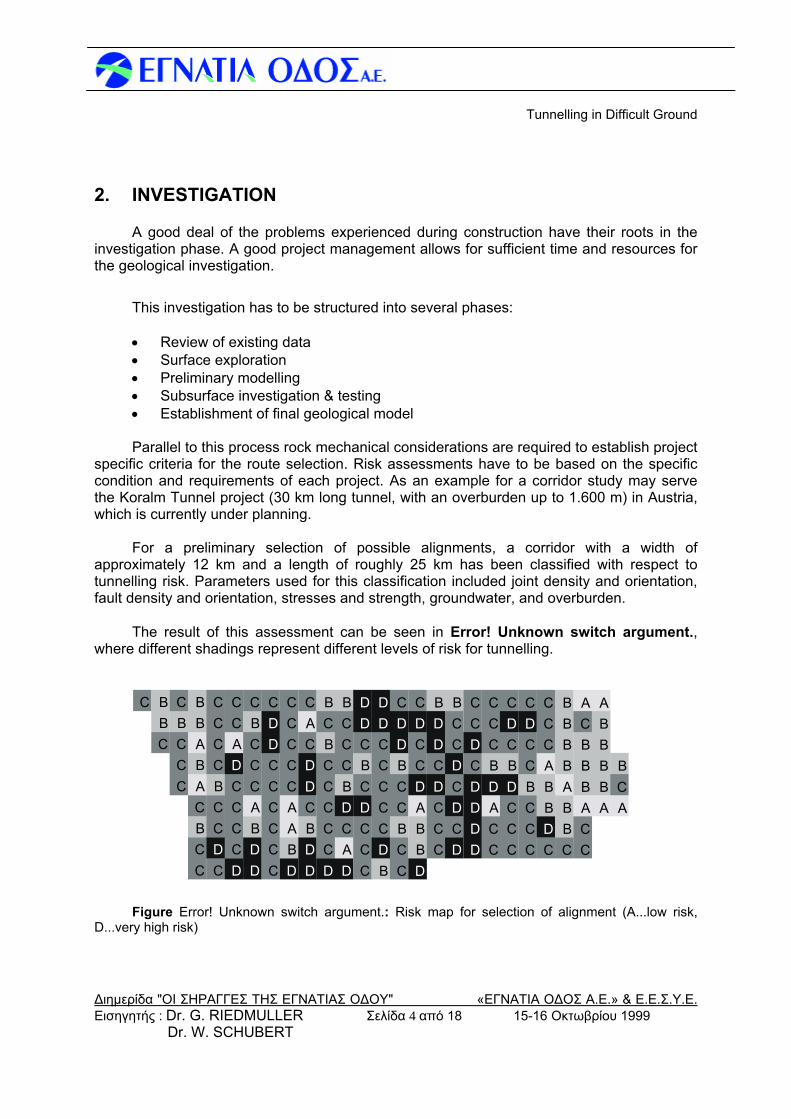
For a preliminary selection of possible alignments, a corridor with a width of
approximately 12 km and a length of roughly 25 km has been classified with respect to tunnelling risk. Parameters used for this classification included joint density and orientation, fault density and orientation, stresses and strength, groundwater, and overburden.
The result of this assessment can be seen in Error! Unknown switch argument.,
where different shadings represent different levels of risk for tunnelling.
C
CBB
CCCBC
CCBCABABB
CDCCBCCCC
DCCCCDACC
DDBACCCBC
CCCCCCDDC
DBAACCCCC
DDBCDDCAC
DCCCCCBCB
DACDBCCCB
CCCDCBCDD
BDCCCCCDD
CCBCCBDDC
DBBADCCDC
CCCDCDDB
DCDCDCCB
DDDDCDCC
CCADBCCC
CCCDBCDC
CCCBCCDC
CDBBACCC
CBBABBBB
CCABBBCA
ABBBBA
ACB
Figure Error! Unknown switch argument.: Risk map for selection of alignment (A...low risk, D...very high risk)
Εισηγητής : Dr. G. RIEDMULLER Σελίδα 4 από 18 15-16 Οκτωβρίου 1999 Dr. W. SCHUBERT
Tunnelling in Difficult Ground
Διημερίδα "ΟΙ ΣΗΡΑΓΓΕΣ ΤΗΣ ΕΓΝΑΤΙΑΣ ΟΔΟΥ" «ΕΓΝΑΤΙΑ ΟΔΟΣ Α.Ε.» & Ε.Ε.Σ.Υ.Ε.
This approach is not limited to tunnels with high overburden, and is not static either. As the level of information increases, criteria and risk map can be refined until a satisfying confidence in the prediction is obtained. The map also helps in selecting locations for surface and subsurface investigation. 3. PRELIMINARY DESIGN
The next step in design should be a preliminary rock mechanical modelling, defining different types of rock mass behaviour along the route, determining or estimating rock mass parameters and analysing stresses and displacements for a selected support.
Analytical models or very simple numerical models can be used for this purpose (9,10).
It should be mentioned, that quantitative classification schemes, like the RMR or Q-
system due to their deficiency in describing the complexity of faulted ground, and missing consideration of the support action never should be used on their own (11).
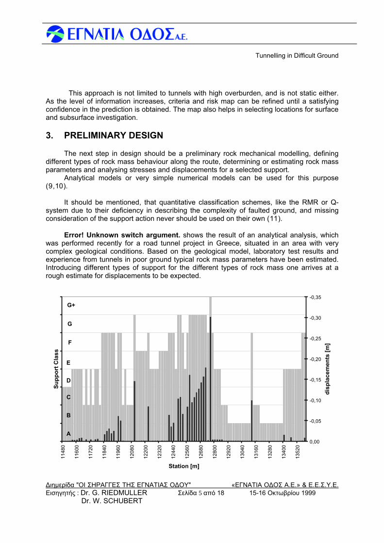
Error! Unknown switch argument. shows the result of an analytical analysis, which
was performed recently for a road tunnel project in Greece, situated in an area with very complex geological conditions. Based on the geological model, laboratory test results and experience from tunnels in poor ground typical rock mass parameters have been estimated. Introducing different types of support for the different types of rock mass one arrives at a rough estimate for displacements to be expected.
1148
0
1160
0
1172
0
1184
0
1196
0
1208
0
1220
0
1232
0
1244
0
1256
0
1268
0
1280
0
1292
0
1304
0
1316
0
1328
0
1340
0
1352
0
Station [m]
Supp
ort C
lass
-0,35
-0,30
-0,25
-0,20
-0,15
-0,10
-0,05
0,00
disp
lace
men
ts [m
]
A
B
C
D
E
F
G
G+
Εισηγητής : Dr. G. RIEDMULLER Σελίδα 5 από 18 15-16 Οκτωβρίου 1999 Dr. W. SCHUBERT
Tunnelling in Difficult Ground
Διημερίδα "ΟΙ ΣΗΡΑΓΓΕΣ ΤΗΣ ΕΓΝΑΤΙΑΣ ΟΔΟΥ" «ΕΓΝΑΤΙΑ ΟΔΟΣ Α.Ε.» & Ε.Ε.Σ.Υ.Ε. Εισηγητής : Dr. G. RIEDMULLER Σελίδα 6 από 18 15-16 Οκτωβρίου 1999 Dr. W. SCHUBERT
Figure Error! Unknown switch argument.: Analysis of displacements (dark columns) along the route of a tunnel, using different support classes (SC, shown shaded in the diagram) designed for the different rock types
In this way very easily parametric studies can be performed, like effectiveness of different support types, variations in rock mass parameters, or effects of different primary stress conditions. In addition critical sections can be identified, and consequently studied in more detail. 4. VERIFICATION OF PRELIMINARY DESIGN
As the analytical approach shown above is a very rough one, preliminarily designed supports should be verified, using numerical simulation models. Due to the considerable effort associated with such simulations, a few typical sections are selected and computed. The model used shall match the geological conditions, which means that for jointed material rather DE-methods will be used, while for more homogeneous ground FE-codes are advantageous. In this phase, modifications to the support, like rock bolt pattern, thickness and quality of lining, etc. can be done. 5. CONSTRUCTION CONTRACT & SUPERVISION
One of the key elements for successful tunnelling is the layout of the construction contract, and the role the owner plays during the execution of works. As the so called geological risk at least to a certain extent will always remain with the owner, it is wise to actively participate in the construction by providing an experienced supervision team.
For geotechnically difficult projects a typical clients site team should include following
qualifications: • Engineer in charge of contractual matters with strong geotechnical background • Geologist for documentation and short term prediction • Geotechnical engineer in charge of evaluation and interpretation of monitoring
data, classification, support layout • Supervisors with the qualification of foreman • Surveying team for displacement monitoring
In some cases, like tunnels with only one heading, or not too complicated geological
conditions, some of the mentioned tasks can be combined and taken care of by one adequately qualified person.
Also the contractor has to have on site personnel with adequate geotechnical
understanding, to be able to jointly decide with the owners representative on all geotechnically relevant matters.
The contract itself has to provide a certain flexibility, in order to be able to optimise construction and support during excavation.
Tunnelling in Difficult Ground
Διημερίδα "ΟΙ ΣΗΡΑΓΓΕΣ ΤΗΣ ΕΓΝΑΤΙΑΣ ΟΔΟΥ" «ΕΓΝΑΤΙΑ ΟΔΟΣ Α.Ε.» & Ε.Ε.Σ.Υ.Ε.
6. GEOLOGICAL & GEOTECHNICAL SITE ASSISTANCE
Data Recording
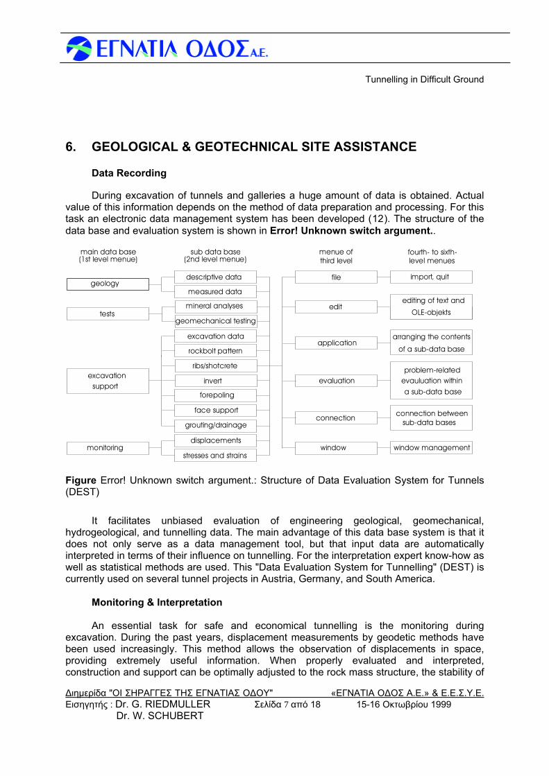
During excavation of tunnels and galleries a huge amount of data is obtained. Actual value of this information depends on the method of data preparation and processing. For this task an electronic data management system has been developed (12). The structure of the data base and evaluation system is shown in Error! Unknown switch argument..
measured data
measured data
geomechanical testing
rockbolt pattern
invert
invertinvert
face support
face supportface supportface support
descriptive data
window
connection
evaluation
application
file
edit
window management
connection between sub-data bases
a sub-data baseevauluation withinproblem-related
arranging the contents
of a sub-data base
OLE-objekts
editing of text and
import, quitgeology
main data base sub data base menue ofthird level level menues
fourth- to sixth-(1st level menue) (2nd level menue)
testsmineral analyses
excavation data
ribs/shotcreteexcavation
support
grouting/drainage
forepoling
stresses and strains
stresses and strainsdisplacementsmonitoring
Figure Error! Unknown switch argument.: Structure of Data Evaluation System for Tunnels (DEST)
It facilitates unbiased evaluation of engineering geological, geomechanical, hydrogeological, and tunnelling data. The main advantage of this data base system is that it does not only serve as a data management tool, but that input data are automatically interpreted in terms of their influence on tunnelling. For the interpretation expert know-how as well as statistical methods are used. This "Data Evaluation System for Tunnelling" (DEST) is currently used on several tunnel projects in Austria, Germany, and South America.
Monitoring & Interpretation
An essential task for safe and economical tunnelling is the monitoring during
excavation. During the past years, displacement measurements by geodetic methods have been used increasingly. This method allows the observation of displacements in space, providing extremely useful information. When properly evaluated and interpreted, construction and support can be optimally adjusted to the rock mass structure, the stability of
Εισηγητής : Dr. G. RIEDMULLER Σελίδα 7 από 18 15-16 Οκτωβρίου 1999 Dr. W. SCHUBERT
Tunnelling in Difficult Ground
Διημερίδα "ΟΙ ΣΗΡΑΓΓΕΣ ΤΗΣ ΕΓΝΑΤΙΑΣ ΟΔΟΥ" «ΕΓΝΑΤΙΑ ΟΔΟΣ Α.Ε.» & Ε.Ε.Σ.Υ.Ε. Εισηγητής : Dr. G. RIEDMULLER Σελίδα 8 από 18 15-16 Οκτωβρίου 1999 Dr. W. SCHUBERT
the tunnel continuously verified, and in combination with the geological documentation data can be used for short term prediction (13).
Although various tools have been developed during the last years to ease
interpretation of monitoring data, rock mechanical expertise and practical experience is required for this task. 7. CASE HISTORIES
The following case histories deal with tunnels in fault zones with moderate overburden (14). Although conditions on the first glance are rather similar, rock mass behaviour showed to be quite different.
Fault Zone at the Inntaltunnel
The ”Inntaltunnel”, a double track tunnel 12.756 m long, penetrates quartzphyllites (”Innsbrucker Quarzphyllit”) which form the Pre-Alpine crystalline basement of the Northern Calcareous Alps. The maximum overburden thickness is approximately 350m. Due to its position at the boundary between Northern Calcareous Alps and the gneiss massif of the Central Zone, the quartzphyllite series have been subjected to intensive tectonic deformation which has generated shear zones oriented generally in the direction of strike of the phyllites (15). A major brittle fault zone intersecting the tunnel axis at an acute angle between stations 2700 m and 4800 m (North Lot), has caused difficulties during tunnel excavation. This fault zone consists of alternating layers of clayey gouge, cataclasite and phyllite, varying in thickness from decimetres to tens of metres. Dipping 20° to 45° to the NW, the fault zone cuts through the gently SW dipping phyllites.
Excavation and support methods were governed by the considerable displacements
observed (see Error! Unknown switch argument.). Near station 2.680 m, deformations exceeded the deformability of conventional shotcrete – rockbolt systems support, resulting in shear failures of the shotcrete lining and broken bolt heads. To increase its deformability, the shotcrete lining of the top heading was divided into three segments with two deformation gaps, a method successfully used previously in similar projects (16,17,18). The rock bolt density was increased and the round length was kept at 1,0 m. The invert arch which was installed followed the bench excavation in a close distance, the distance to the heading face being between 100 and 120 m.
From station 2.680 m to approximately station 3.170 m, crown settlements ranged from
3 to 15 cm after one day, with final settlements of 30 cm to 60 cm. As the deformation gaps in sections with higher displacements closed completely, occasionally leading to severe lining damage, the number of deformation gaps in the top heading lining was increased to four, plus free footings, to prevent shearing of the lining. Maximum roof settlements reached 120 cm around station 3.230.
The end of the fault zone was reached near station 4.800 m and crown settlements
over the last 1.500 m of the fault zone continuously decreased, averaging around 40 cm.
Tunnelling in Difficult Ground
Διημερίδα "ΟΙ ΣΗΡΑΓΓΕΣ ΤΗΣ ΕΓΝΑΤΙΑΣ ΟΔΟΥ" «ΕΓΝΑΤΙΑ ΟΔΟΣ Α.Ε.» & Ε.Ε.Σ.Υ.Ε.
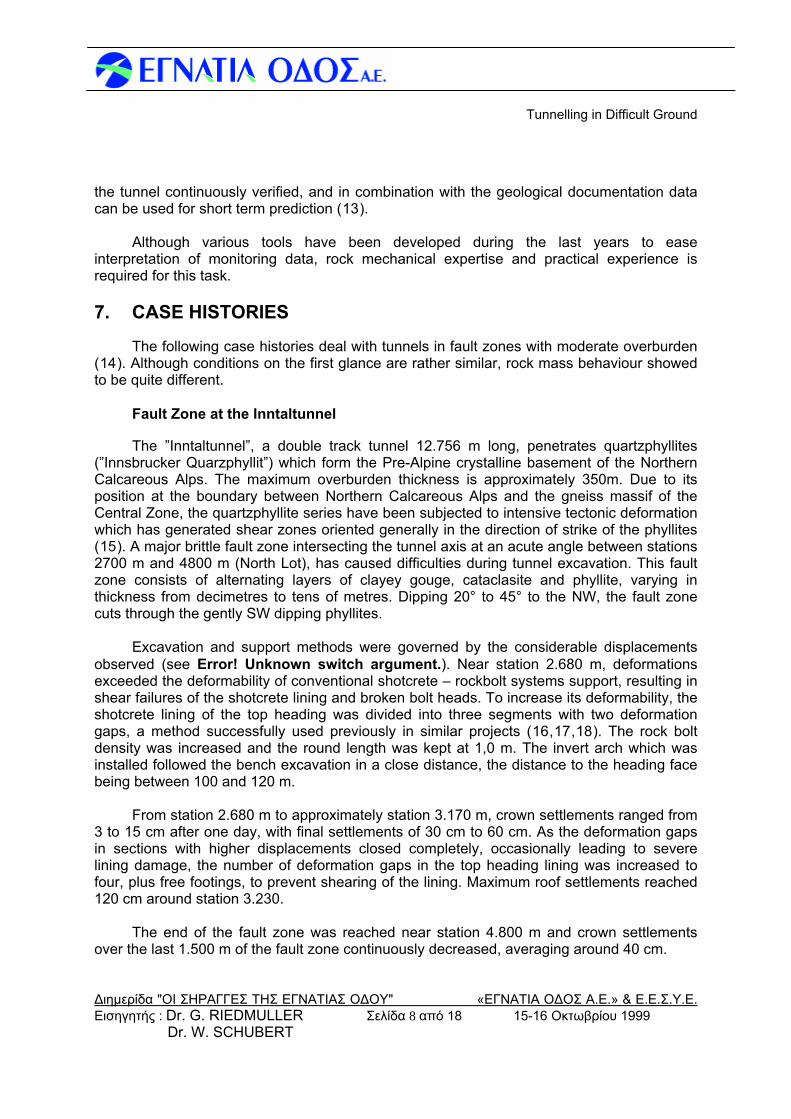
The number of rockbolts with lengths of 6 and 8 m varied from 17 to a maximum of 29 per linear meter of top heading throughout the fault zone, while round length and shotcrete thickness were kept constant at 1,0 m and 20 cm, respectively.
-1,40
-1,20
-1,00
-0,80
-0,60
-0,40
-0,20
0,00
2500 3000 3500 4000 4500 5000Stationierung [m]
[m]
Figure Error! Unknown switch argument.: Crown settlements along the fault zone at the Inntaltunnel
The main influencing factors of displacement were shear planes striking more or less parallel to the tunnel axis and dipping to the NW. The combination of foliation and shear planes generated wedge type failures on the right sidewall, influencing the orientation of the displacement vectors. The difference in longitudinal displacements between the left and right sidewall of several centimetres was remarkable.
In general displacement rates decreased smoothly indicating a “normal” stabilisation
process. The varying stiffness of the rock mass within the fault zone made prediction of final displacements rather difficult. In a few areas, the amount of deformation was underestimated, requiring reshaping of the tunnel prior to installation of the inner lining.
Although the amount of displacement varied widely in short distances, the general
behaviour of the rock mass was very similar throughout the fault zone and operations could continue routinely at an excavation rate of around 4 m per day.
Fault Zones at the Galgenbergtunnel The NE -SW oriented ”Galgenbergtunnel” has a total length of 6.108 m. The maximum
overburden thickness is 260 m. The tunnel cuts through extremely variable ground, consisting of gneisses, quartzites, phyllites, greenschists and marbles, belonging to different tectonic units.
Εισηγητής : Dr. G. RIEDMULLER Σελίδα 9 από 18 15-16 Οκτωβρίου 1999 Dr. W. SCHUBERT
Tunnelling in Difficult Ground
Διημερίδα "ΟΙ ΣΗΡΑΓΓΕΣ ΤΗΣ ΕΓΝΑΤΙΑΣ ΟΔΟΥ" «ΕΓΝΑΤΙΑ ΟΔΟΣ Α.Ε.» & Ε.Ε.Σ.Υ.Ε. Εισηγητής : Dr. G. RIEDMULLER Σελίδα 10 από 18 15-16 Οκτωβρίου 1999 Dr. W. SCHUBERT
The folded and faulted lithological series trending generally WSW - ENE intersect the tunnel axis at an acute angle. The two major fault zones, the ”Hinterberg” fault and the ”Haberl” fault, have proved to be excessively difficult to tunnel through (19, 20, 21).
Hinterberg Fault
This fault zone, located between station 959 m and 1.342 m (heading Leoben), has
developed between two units of massive marble. Source rocks are imbricated graphitic and carbonatic phyllites, greenschists and thinly bedded marbles of the Paleozoic, Upper Austroalpine Greywacke zone (”Veitscher Decke”). The orientation of foliation planes indicate a E -W trending syncline structure with a fold axis dipping gently to the west. Slickensided shear planes most commonly dip steeply to the SSE and occasionally to the SE and NE.
The main characteristic of this fault zone is its extreme heterogeneity concerning the
ratio of soft, clayey gouges to variably fractured rock mass. Despite a chaotic fault structure, it has been confirmed by statistical evaluation that the amount of clayey gouges and the degree of rock mass fracturing increases significantly from NE to SW. It is pointed out that a collapse happened in July 1994 at the southeastern boundary of the fault zone.
The location of the Hinterberg fault zone was precisely predicted. Due to the
heterogeneity of the rock mass, prediction of the tunnel performance was extremely difficult. Sections with low initial deformation exhibited long lasting displacements, while other sections stabilised rather quickly after high initial displacements. Determining the amount of overexcavation and support required was therefore extremely difficult. At the beginning of the fault zone, a rather stiff support approach was believed to limit deformations to amounts the lining could sustain. Due to severe damages, the method was soon changed to one similar as used at the Inntaltunnel. The size of top heading, lining thickness, rock bolt density, and round length were comparable, but the invert followed the heading face in a closer distance than at the Inntaltunnel.
When the excavation approached the end of the fault zone, a sudden collapse at the
face of the top heading occurred without warning. The ensuing investigation revealed that a combination of unfavourable circumstances caused the failure, including:
• Sudden alternations of relatively stiff and soft sheared rocks. • Low friction angle of the fault gouge ( f = 12° -14° ). • Unusual primary stress situation.
From the trend of the displacement vector orientations, it could be deduced that an arch type initial stress situation exists within the fault zone (see Error! Unknown switch argument., middle). This unusual primary stress condition is caused by a post glacial lateral creeping of the fault material wedged in between the two massive marble units. This resulted in a higher maximum principal stress, and the development of potential shear failures in directions not usually experienced during tunnelling (22). Long lasting displacements in certain sections of the fault zone required additional bolting and partial reshaping.
Tunnelling in Difficult Ground
Διημερίδα "ΟΙ ΣΗΡΑΓΓΕΣ ΤΗΣ ΕΓΝΑΤΙΑΣ ΟΔΟΥ" «ΕΓΝΑΤΙΑ ΟΔΟΣ Α.Ε.» & Ε.Ε.Σ.Υ.Ε. Εισηγητής : Dr. G. RIEDMULLER Σελίδα 11 από 18 15-16 Οκτωβρίου 1999 Dr. W. SCHUBERT
Haberl Fault
The ”Haberl” fault was encountered between stations 1.760 m and 1.990 m (heading Jassing Ost). The fault zone developed in graphitic phyllites and occasionally greenschists, meta-sandstones, calcareous phyllites and platy marbles of the greywacke zone. The undulating, most commonly sheared foliation planes generally dip gently to the south. Additional shearing, which generated clayey gouges and fault breccia, took place on moderately to steeply NE and SW dipping shear planes.
The ”Haberl” fault zone is characterised by pervasive homogeneous shearing which
shows brittle and ductile deformation features. From the geotechnical standpoint, the most important feature of the fault zone is the alternating sequence of hard and soft rock layers. within the fault zone exists.
With the experience from the Hinterberg fault, it was agreed that the support and
excavation approach should be modified for the Haberl fault (20, 23.) The modifications included:
• reduction of the top heading height to 4,5 m to increase face stability • use of 8 to 12 m long regroutable self drilling bolts (IBI) • integration of yielding steel elements in the shotcrete lining The aim of the modifications was to reduce displacements in the excavation area and
to guarantee rock bolt performance even after big deformations, thus increasing stability and safety. Technically the solution was convincing. Final displacements did not exceed 15 cm, nearly a magnitude smaller than at the Hinterberg fault zone. At no time was there any sign of instability.
The reduction of displacements in the soft rock layers prevented high stress
concentrations in the hard rock layers. Thus the risk of a brittle failure of the stiff layers as experienced in the Hinterberg fault zone was minimised.
Due to the time consuming bolt installation and the reduction of the top heading height,
the excavation rate could not be increased over an average of 1,70 m per day, increasing construction time and cost. On the other hand, no reshaping or repairs were required on the 350 m of tunnel where this approach was applied.
8. CONCLUSION
The three tunnels presented in the case studies had the same diameter, the same range of overburden thickness in sections of fault zones, as well as similar lithology, discontinuity structure and strength properties of the rock mass. Despite these similarities the performance of the tunnels was remarkably different. The excavation in the “Inntaltunnel fault” was generally characterised by gradual transitions between different rock mass behaviour. The significant feature of tunnelling through the “Hinterberg fault zone” was abrupt
Tunnelling in Difficult Ground
Διημερίδα "ΟΙ ΣΗΡΑΓΓΕΣ ΤΗΣ ΕΓΝΑΤΙΑΣ ΟΔΟΥ" «ΕΓΝΑΤΙΑ ΟΔΟΣ Α.Ε.» & Ε.Ε.Σ.Υ.Ε. Εισηγητής : Dr. G. RIEDMULLER Σελίδα 12 από 18 15-16 Οκτωβρίου 1999 Dr. W. SCHUBERT
changes of deformability and displacement vector orientation. The excavation in the “Haberl fault” zone was dominated by mixed face conditions with alternating stiff and soft rock layers. Deformation magnitudes in the fault zone did not differ significantly.
The different rock mass behaviour in the three fault zones is illustrated in Error!
Unknown switch argument..
Tunnelling in Difficult Ground
Διημερίδα "ΟΙ ΣΗΡΑΓΓΕΣ ΤΗΣ ΕΓΝΑΤΙΑΣ ΟΔΟΥ" «ΕΓΝΑΤΙΑ ΟΔΟΣ Α.Ε.» & Ε.Ε.Σ.Υ.Ε.
1000 1100900 1200 1300chainage
LS
LS
0
[°]
20
10
30
-30
-20
-10mon
itorin
g
vector-orientation
excavationstep
12 3
1
70°50°30°10°
1760chainage
0
[°]
20
10
30
-30
-20
-10
1
mon
itorin
g
excavationstep
vector-orientation
2 3
1840 18801800 1920 1960 2000 2040
LS
70°50°30°10°
1
70°50°30°10°1
2
3
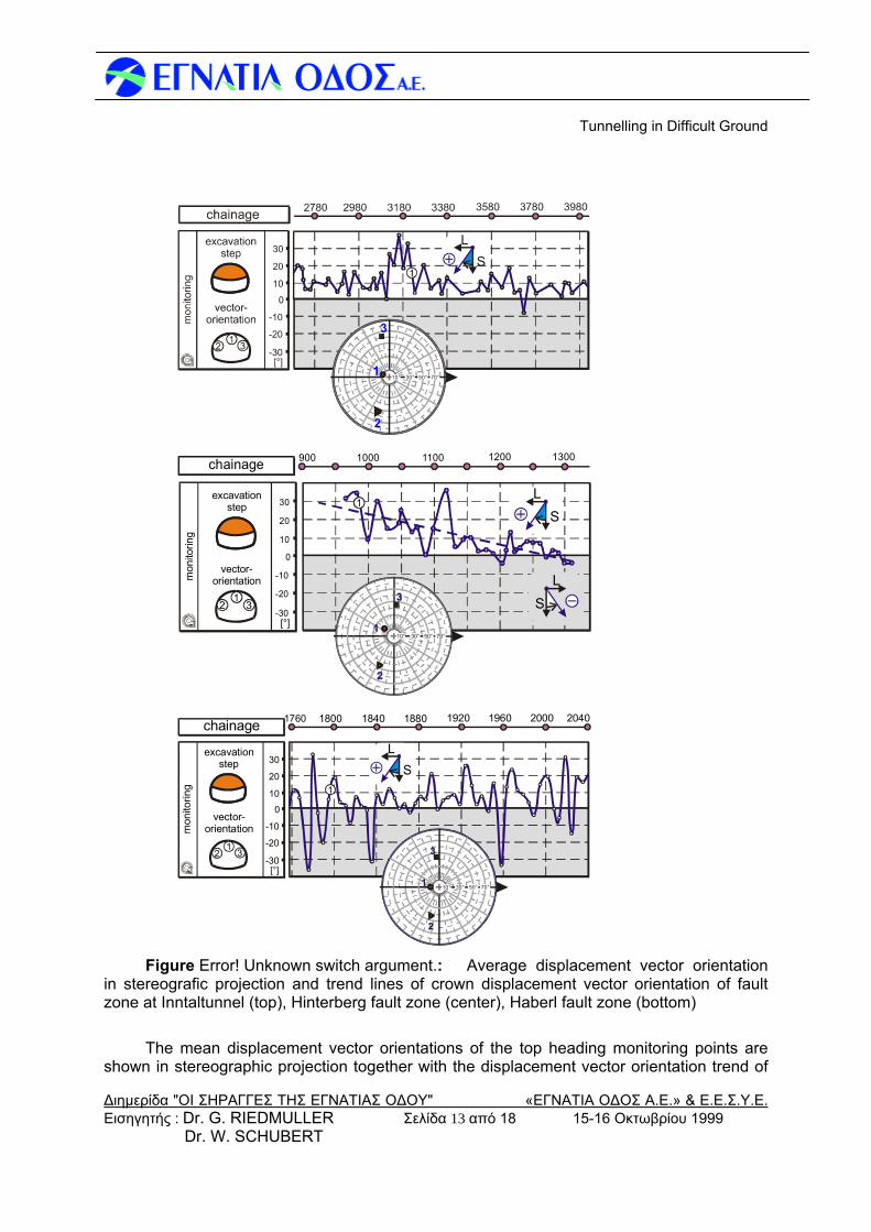
Figure Error! Unknown switch argument.: Average displacement vector orientation
in stereografic projection and trend lines of crown displacement vector orientation of fault zone at Inntaltunnel (top), Hinterberg fault zone (center), Haberl fault zone (bottom)
The mean displacement vector orientations of the top heading monitoring points are
shown in stereographic projection together with the displacement vector orientation trend of
Εισηγητής : Dr. G. RIEDMULLER Σελίδα 13 από 18 15-16 Οκτωβρίου 1999 Dr. W. SCHUBERT
Tunnelling in Difficult Ground
Διημερίδα "ΟΙ ΣΗΡΑΓΓΕΣ ΤΗΣ ΕΓΝΑΤΙΑΣ ΟΔΟΥ" «ΕΓΝΑΤΙΑ ΟΔΟΣ Α.Ε.» & Ε.Ε.Σ.Υ.Ε. Εισηγητής : Dr. G. RIEDMULLER Σελίδα 14 από 18 15-16 Οκτωβρίου 1999 Dr. W. SCHUBERT
the crown along the fault zones. The vector orientation trend in the fault zone at the Inntaltunnel is changing gradual as tunnelling advances showing only small variations except when approaching the most unfavourable rock mass at around station 3.290 m. The trend of vector orientation of the “Hinterberg fault zone” shows a significant trend indicating the arch- like orientation of initial principal stress orientation. Strong local variations of displacement vector orientation point to the heterogeneity and abrupt changes in rock mass stiffness. In the “Haberl fault” the vector orientations vary widely, reflecting the complicated structure of this fault zone with sudden changes between stiff and soft rocks.
The lessons learned from tunnelling through the three fault zones are: • The more heterogeneous the rock mass is, the more care has to be taken in the
support selection. It turned out that even large units of competent rock within faulted rocks have to be heavily reinforced, as they are subject to stress concentration
• A key parameter for the performance of the tunnel is the internal angle of friction of
the rock mass. Consequently, more attention should be paid to the determination of this crucial parameter during investigation.
• The vector orientation trend is a reliable indicator of variations in rock mass
stiffness ahead of the face and should be used routinely for short term prediction when tunnelling through a fault zone (24,25,Error! Unknown switch argument.,26)
• Tunnelling through fault zones is costly and time consuming. Careful engineering
and continuous updating of the design based on monitoring data and increased knowledge of the geological structure and material parameters at site are essential for successful tunnel construction. Successful mastering of fault zones also requires the satisfactory solution of many practical details of excavation and support
• There is still room for improvement of support elements. Recent investigations led
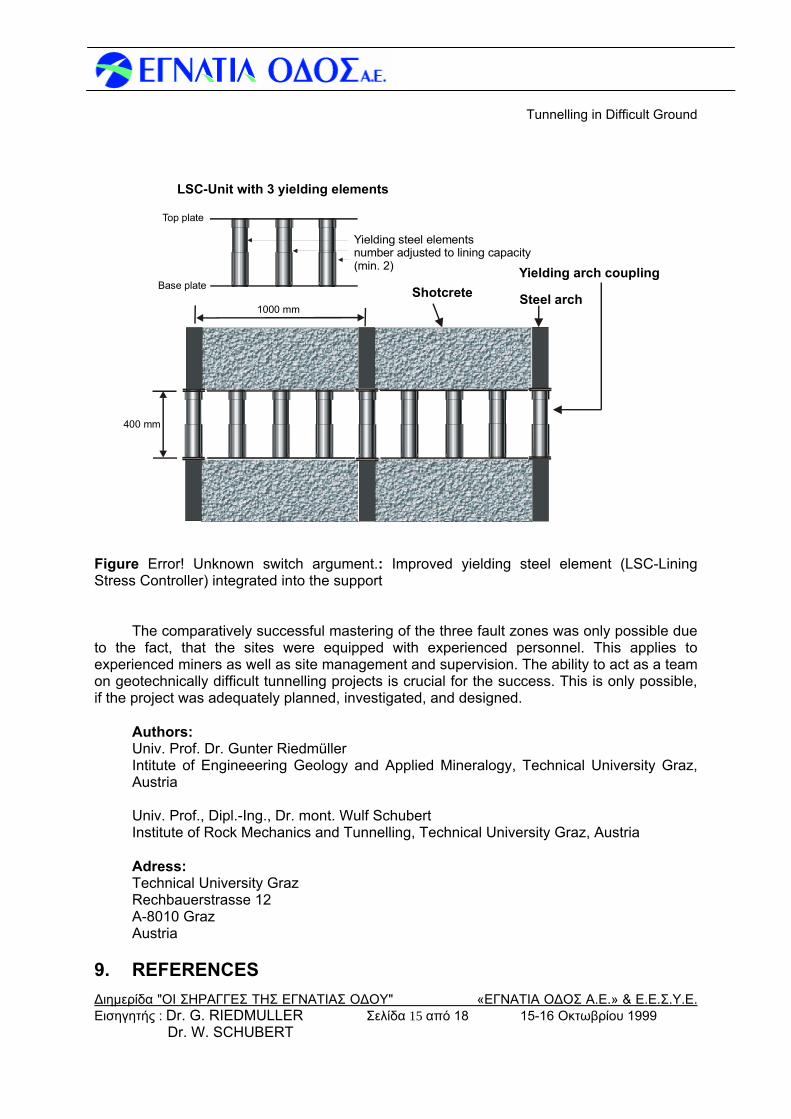
to an improvement of rock bolts for use in poor ground conditions (27). The integration of yielding elements into the lining allows a better use of the lining capacity, while limiting the lining stresses to a level well below its capacity. Improvements on the system have been made by our group (28,29) (see Error! Unknown switch argument.). The effect of yielding elements integrated into the lining are also described in (30).
• It still is very difficult to predict the final convergence of a tunnel in a heterogeneous
ground. Research is currently carried out in our group to develop a tool for a reliable prediction of displacements, based on the data base DEST, displacement monitoring data, and short term prediction (31). With this tool in future it should be possible to minimise reshaping of tunnels due to excessive convergence.
Tunnelling in Difficult Ground
Διημερίδα "ΟΙ ΣΗΡΑΓΓΕΣ ΤΗΣ ΕΓΝΑΤΙΑΣ ΟΔΟΥ" «ΕΓΝΑΤΙΑ ΟΔΟΣ Α.Ε.» & Ε.Ε.Σ.Υ.Ε.
LSC-Unit with 3 yielding elements
Steel arch
Yielding arch couplingShotcreteBase plate
Top plate
Yielding steel elementsnumber adjusted to lining capacity(min. 2)
400 mm
1000 mm
Figure Error! Unknown switch argument.: Improved yielding steel element (LSC-Lining Stress Controller) integrated into the support
The comparatively successful mastering of the three fault zones was only possible due
to the fact, that the sites were equipped with experienced personnel. This applies to experienced miners as well as site management and supervision. The ability to act as a team on geotechnically difficult tunnelling projects is crucial for the success. This is only possible, if the project was adequately planned, investigated, and designed.
Authors: Univ. Prof. Dr. Gunter Riedmüller Intitute of Engineeering Geology and Applied Mineralogy, Technical University Graz, Austria Univ. Prof., Dipl.-Ing., Dr. mont. Wulf Schubert Institute of Rock Mechanics and Tunnelling, Technical University Graz, Austria Adress: Technical University Graz Rechbauerstrasse 12 A-8010 Graz Austria
9. REFERENCES
Εισηγητής : Dr. G. RIEDMULLER Σελίδα 15 από 18 15-16 Οκτωβρίου 1999 Dr. W. SCHUBERT
Tunnelling in Difficult Ground
Διημερίδα "ΟΙ ΣΗΡΑΓΓΕΣ ΤΗΣ ΕΓΝΑΤΙΑΣ ΟΔΟΥ" «ΕΓΝΑΤΙΑ ΟΔΟΣ Α.Ε.» & Ε.Ε.Σ.Υ.Ε. Εισηγητής : Dr. G. RIEDMULLER Σελίδα 16 από 18 15-16 Οκτωβρίου 1999 Dr. W. SCHUBERT
1. Mandl, G. (1988): Mechanics of tectonic faulting.- Developments in structural
geology, H.J.Zwart (Ed.), Elsevier, 407 pp. 2. Scholz, Ch.H. (1990): The mechanics of earthquakes and faulting.- Cambridge
University Press, 439 pp. 3. Twiss, R. J. & Moores E. M. (1992): Structural geology.- Freeman, 532 pp. 4. Klima, K., Riedmüller, G., Stattegger, K. (1988): Statistical analysis of clay
mineral assemblages in fault gouges.- Clays and Clay Minerals, Vo. 36, No.3, 277 - 283. 5. Riedmüller, G. (1978): Neoformation and transformation of clay minerals in
tectonic shear zones.- Tschermaks Min.Petr.Mitt. 25, 219 - 242. 6. Wu, F. T. (1978): Mineralogy and physical nature of clay gouge.- Pure Appl.
Geophys.,116, pp 655 - 689. 7. Goodman, R. E. (1993): Engineering geology.- John Wiley & Sons,Inc.,412
pp. 8. Riedmüller, G. (1997): Rock characterization for tunnelling: Engineering
geologist’s point of view.- Felsbau, 15, 3, 167 - 170 9. Hoek, E. (1999): Support for very weak rock associated with faults and shear
zones; Proceedings Int. Symp. on Rock Support and Reinforcement Practice in Mining, Kalgoorlie, Australia
10. Feder, G. (1977): Zum Stabilitätsnachweis für Hohlräume in festem Gebirge
bei richtungsbetontem Primärdruck; Berg und Hüttenmännische Monatshefte, Jahrgang 122, Vol. 4
11. Riedmüller, G., Schubert W. (1999): Critical comments on quantitative rock
mass classifications, FELSBAU 17, Nr. 3 164-167 12. Liu, Q., et.al.: Evaluation of data during tunnelling by using an expert system,
Tunnels for People, Golser, Hinkel, Schubert (eds), pp 97-102, 1997 Balkema, Rotterdam 13. Steindorfer, A.(1998): Short term Prediction of Rock Mass Behaviour in
Tunnelling by Advanced Analysis of Displacement Monitoring Data, Gruppe Geotechnik Graz, Riedmüller, Schubert, Semprich (eds), Heft 1
14. Schubert, W.; Riedmüller, G.: Influence of Faults on Tunnelling, Felsbau 15,
No. 6, 1997 15. Leimser, W. & Köhler, M. (1994): Die baugeologischen Verhältnisse des
Inntaltunnels.- Felsbau, 2/94, 69 - 76.
Tunnelling in Difficult Ground
Διημερίδα "ΟΙ ΣΗΡΑΓΓΕΣ ΤΗΣ ΕΓΝΑΤΙΑΣ ΟΔΟΥ" «ΕΓΝΑΤΙΑ ΟΔΟΣ Α.Ε.» & Ε.Ε.Σ.Υ.Ε. Εισηγητής : Dr. G. RIEDMULLER Σελίδα 17 από 18 15-16 Οκτωβρίου 1999 Dr. W. SCHUBERT
16. Rabcewicz, L.v., Hackl, E. (1975) Die Bedeutung der Messung im
Hohlraumbau III, Erfahrungen beim Tauerntunnel. Der Bauingenieur, 50, 369-379, Springer Verlag
17. Schubert, P., Marinko, T.(1989): Vortrieb des Karawankentunnels im
tektonisch stark beanspruchten Südabschnitt. Felsbau 7, Vol. 2; Verlag Glückauf 18. Schubert W., Schubert P. (1993) Tunneling in squeezing rock: failure
phenomena and counteractions. Proceedings Int. Symp. on Assessment and Prevention of Failure Phenomena in Rock Engineering, Istanbul 1993, Balkema pp 479-484
19. Bergmair, M., Harer, G., Riedmüller, G. and Stadlmann, Th. (1996): Die
Baugeologie des Galgenbergtunnels.- Felsbau, 1/96, 15 - 20. 20. Harer, G., Prein, R., Schwab, P. and Wehr, H. (1996): Tunnelling in poor
ground conditions - case history Galgenbergtunnel.- Felsbau 2/96, 82 - 86. 21. Riedmüller, G. (1997): Rock characterization for tunnelling: Engineering
geologist’s point of view.- Felsbau, 15, 3, 167 - 170. 22. Schubert, W., Riedmüller,G. (1995): “Geotechnische Nachlese eines
Verbruches - Erkenntnisse und Impulse”, Mitteilungsheft 13, 10. Christian Veder Kolloquium, “Innovation in der Geotechnik” vom Inst. für Bodenmechanik und Grundbau, TU-Graz, pp 59 – 68
23. Schubert, W., Golser, J., Schwab, P.(1996): Weiterentwicklung des Ausbaues
für stark druckhaftes Gebirge; Felsbau 14, Vol. 1 , 6-42 24. Schubert W., Budil A. (1995): The importance of longitudinal deformation in
tunnel excavation, Proc. 8th Int. Congr. on Rock Mechanics, Balkema Rotterdam, Vol. 3 25. Steindorfer, A., Schubert, W. (1997): “Application of new methods of
monitoring data analysis for short term prediction in tunnelling”; Proc. ITA World Tunnel Congress 97, Vienna, Vol. I, pp 65-69, Balkema Rotterdam
26. Schubert, W. (1996): “Dealing with squeezing conditions in Alpine Tunnels”,
Rock Mechanics and Rock Engineering, Vol. 29, No. 3, pp 145-153, Springer Verlag Wien 27. Blümel, M.( 1996): ”Performance of Grouted Bolts in Squeezing Rock”.
Proceedings ISRM Int. Symposium on ”Prediction and Performance in Rock Mechanics and Rock Engineering”, Eurock `96, Torino Italy, Balkema Rotterdam, pp. 885-891
28. W. Schubert, B. Moritz (1998): Controllable Ductile Support System for
Tunnels in Squeezing Rock, Felsbau 16, No.4
Tunnelling in Difficult Ground
Διημερίδα "ΟΙ ΣΗΡΑΓΓΕΣ ΤΗΣ ΕΓΝΑΤΙΑΣ ΟΔΟΥ" «ΕΓΝΑΤΙΑ ΟΔΟΣ Α.Ε.» & Ε.Ε.Σ.Υ.Ε. Εισηγητής : Dr. G. RIEDMULLER Σελίδα 18 από 18 15-16 Οκτωβρίου 1999 Dr. W. SCHUBERT
29. Moritz, B. (1999): Ductile support system for tunnels in squeezing rock, Ph.D.
thesis, Technical University Graz 30. Pöttler, R.: Über die Wirkungsweise einer geschlitzten Spritzbetonschale,
Felsbau 15, (1997) Nr.6, pp 422-429 31. Schubert, W., Moritz, B., Sellner, P., Blümel, M. (1999): Tunnelling in
squeezing ground – recent improvements; FELSBAU 17, Nr.1, 56-58