Objective Heat Exchangers Learn about different types Define Heat Exchanger Effectivness (ε)...
28
Objective • Heat Exchangers • Learn about different types • Define Heat Exchanger Effectivness (ε) • Analyze how geometry affects ε • Solve examples
-
Upload
britton-griffith -
Category
Documents
-
view
218 -
download
0
Transcript of Objective Heat Exchangers Learn about different types Define Heat Exchanger Effectivness (ε)...
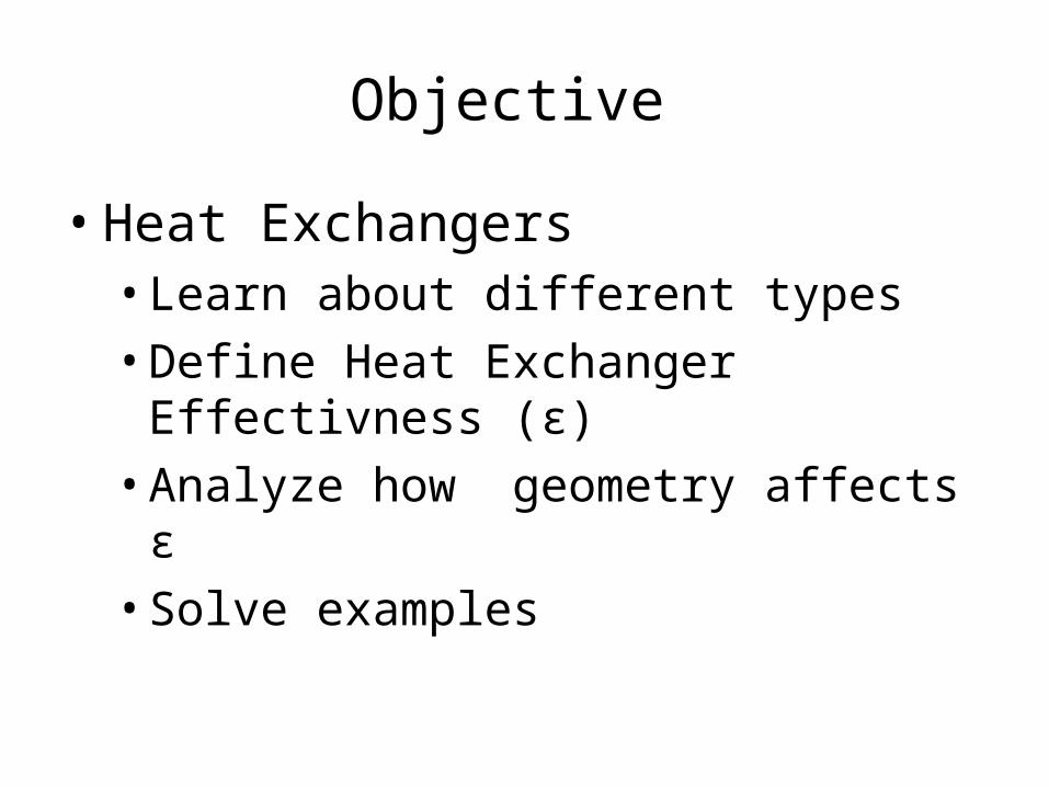
Objective
• Heat Exchangers• Learn about different types
• Define Heat Exchanger Effectivness (ε)
• Analyze how geometry affects ε
• Solve examples
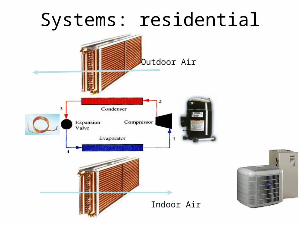
Systems: residential
Indoor Air
Outdoor Air
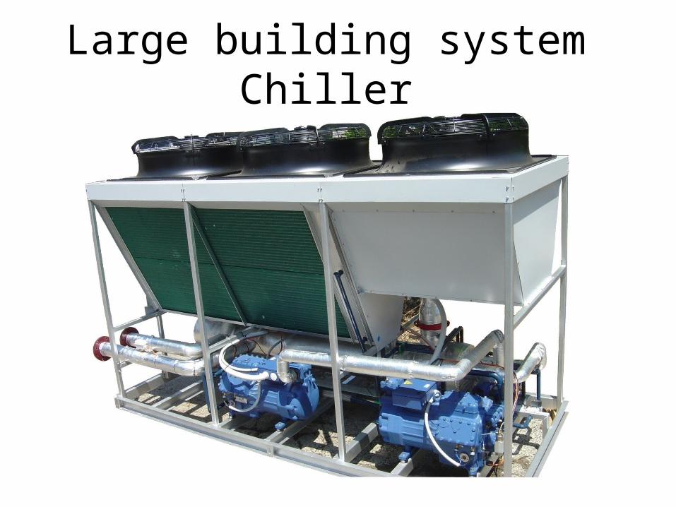
Large building system Chiller
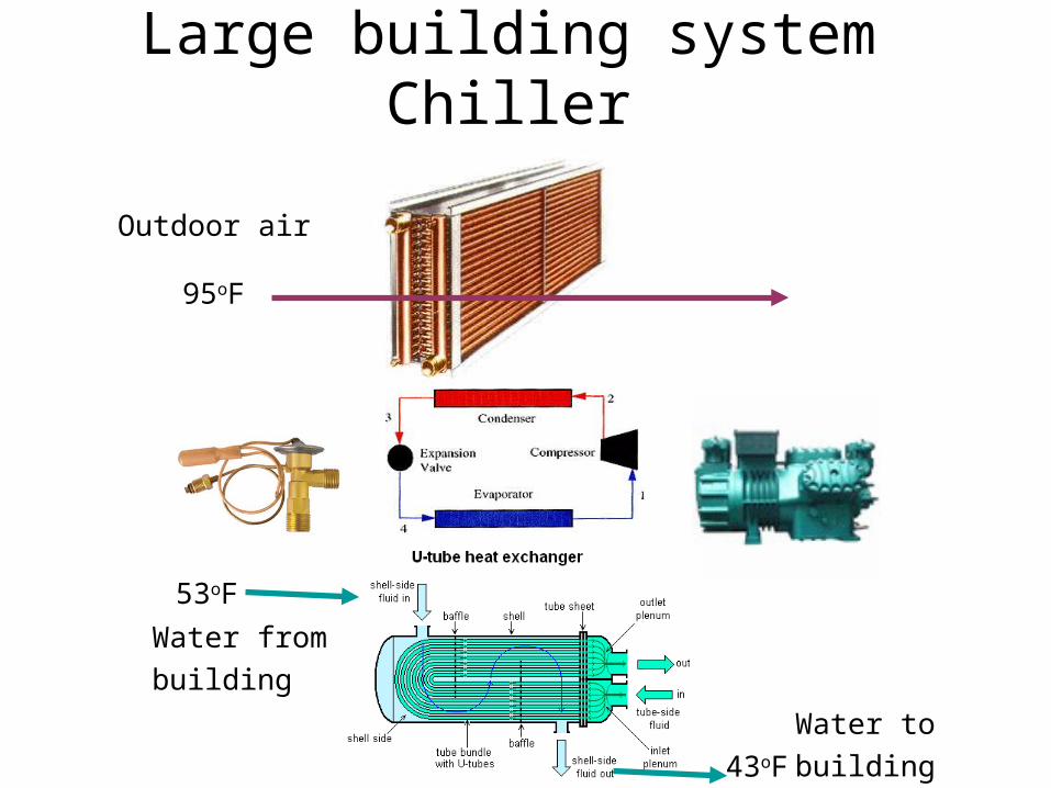
Large building system Chiller
Outdoor air
53oF
43oF
Water to
building
Water from
building
95oF
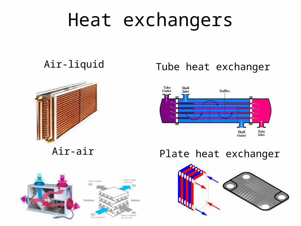
Air-liquid Tube heat exchanger
Plate heat exchanger
Heat exchangers
Air-air
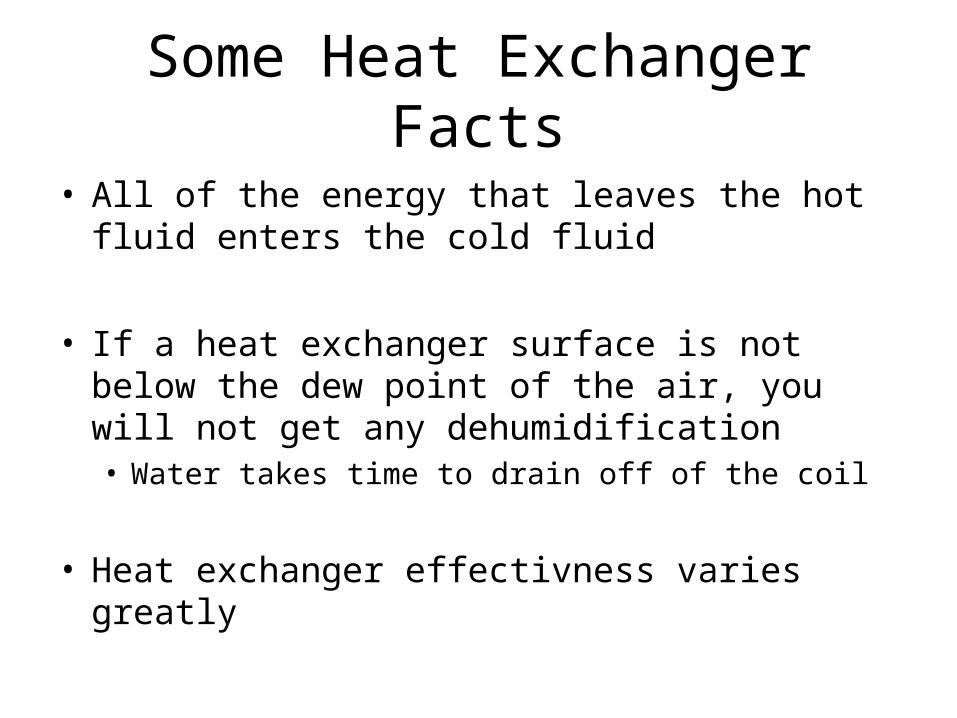
Some Heat Exchanger Facts
• All of the energy that leaves the hot fluid enters the cold fluid
• If a heat exchanger surface is not below the dew point of the air, you will not get any dehumidification• Water takes time to drain off of the coil
• Heat exchanger effectivness varies greatly
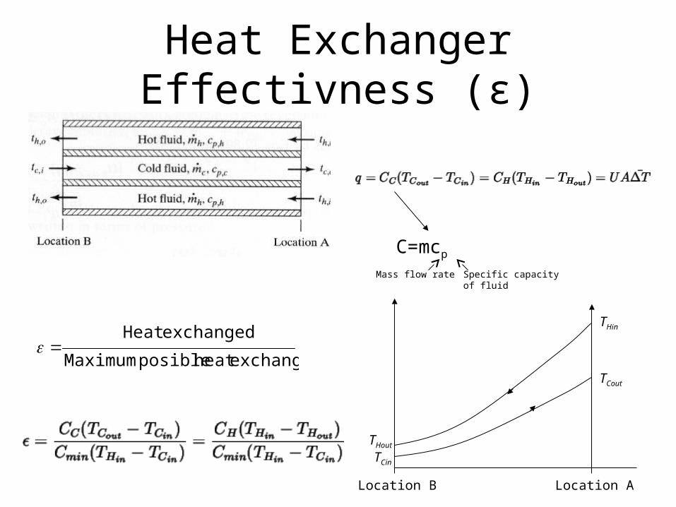
Heat Exchanger Effectivness (ε)
C=mcp
exchangeheatposible Maximum
exchangedHeat
Location B Location A
THout
TCin
TCout
THin
Mass flow rate Specific capacity of fluid
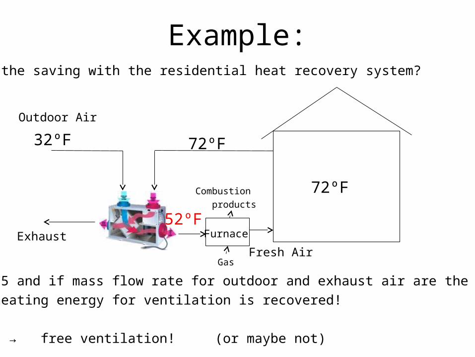
Example:What is the saving with the residential heat recovery system?
Furnace
72ºF
32ºF 72ºF
Outdoor Air
For ε=0.5 and if mass flow rate for outdoor and exhaust air are the same
50% of heating energy for ventilation is recovered!
For ε=1 → free ventilation! (or maybe not)
52ºF Exhaust
Gas
Combustion
products
Fresh Air
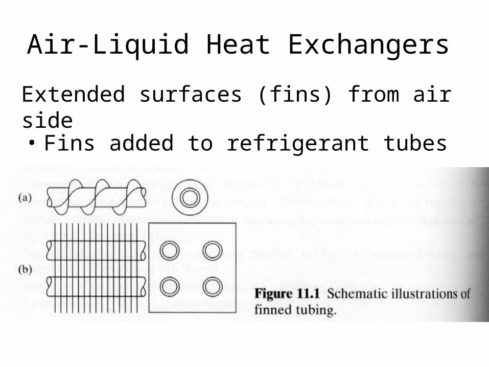
Air-Liquid Heat Exchangers
• Fins added to refrigerant tubes
Extended surfaces (fins) from air side
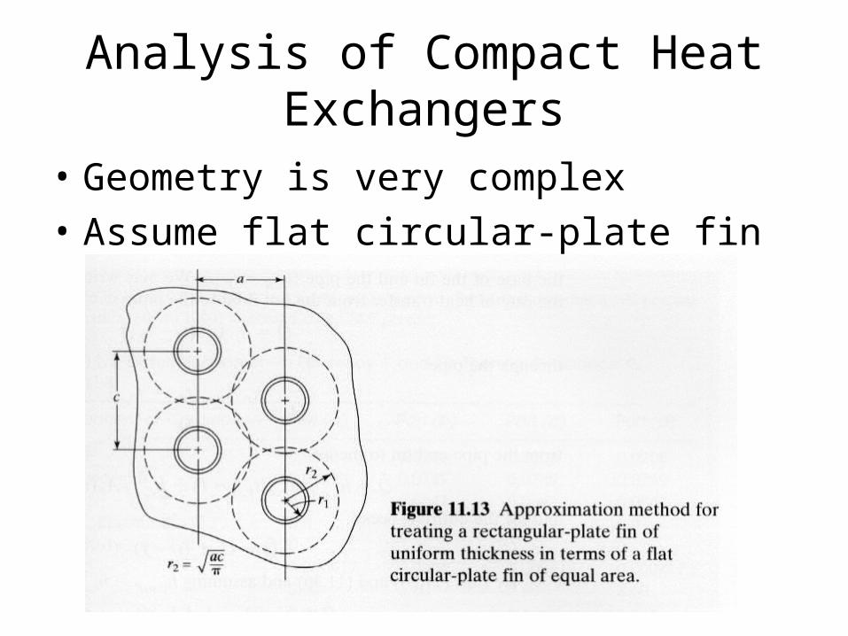
Analysis of Compact Heat Exchangers
• Geometry is very complex
• Assume flat circular-plate fin
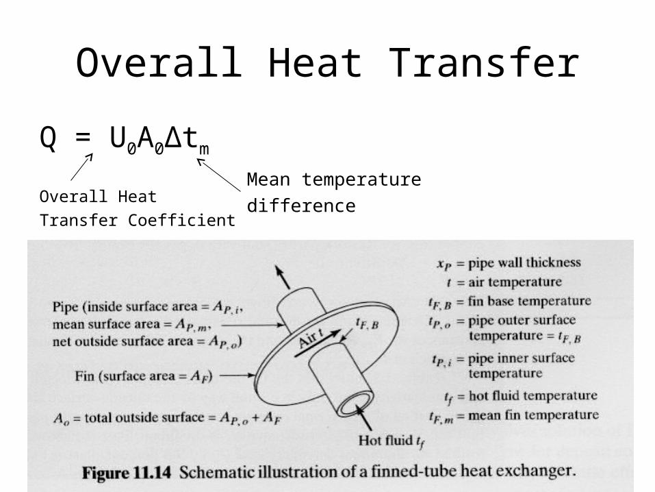
Overall Heat Transfer
Q = U0A0Δtm
Overall Heat
Transfer Coefficient
Mean temperature
difference
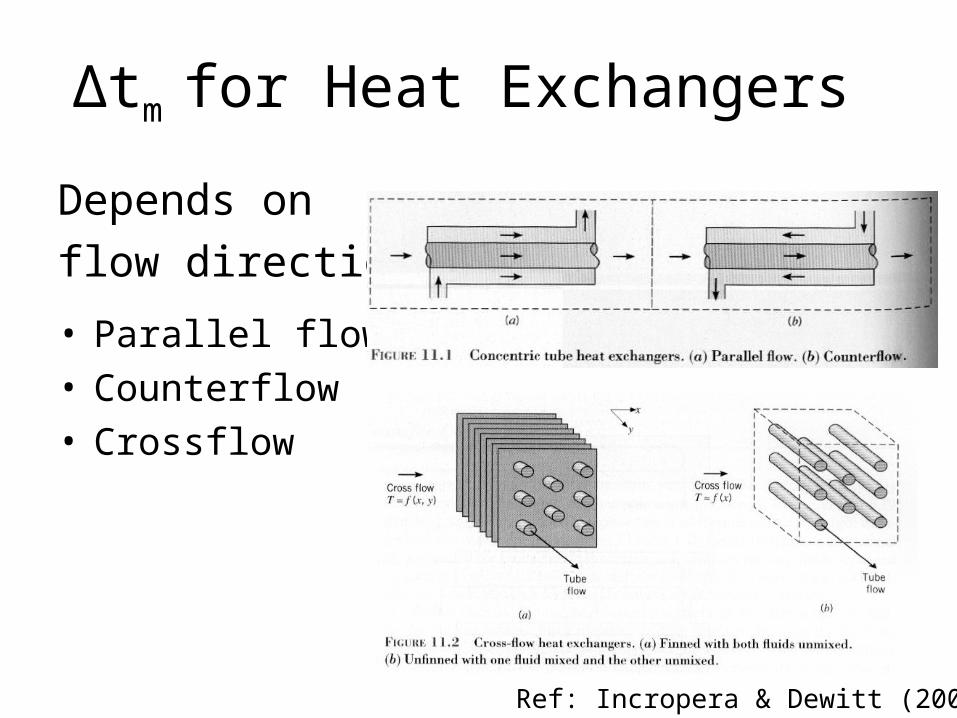
Δtm for Heat Exchangers
Depends on
flow direction:
• Parallel flow• Counterflow• Crossflow
Ref: Incropera & Dewitt (2002)
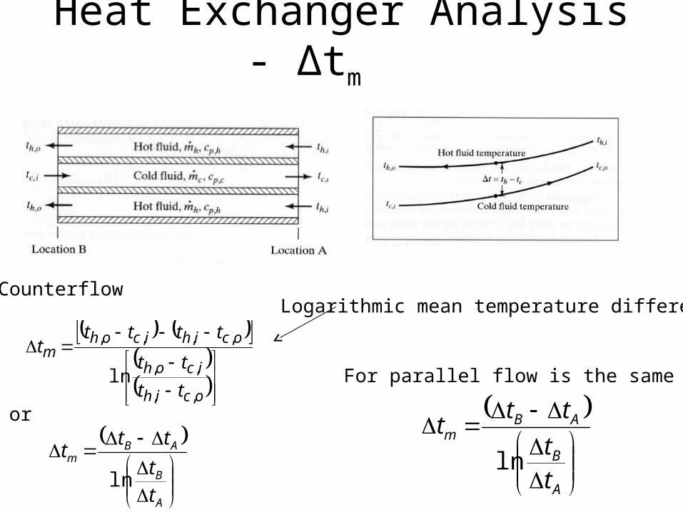
Heat Exchanger Analysis - Δtm
ocih
icoh
ocihicohm
tt
tt
ttttt
,,
,,
,,,,
ln
Counterflow
A
B
ABm
tt
ttt
ln
For parallel flow is the same
or
A
B
ABm
tt
ttt
ln
Logarithmic mean temperature difference
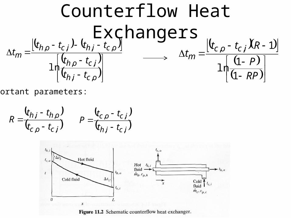
Counterflow Heat Exchangers
ocih
icoh
ocihicohm
tt
tt
ttttt
,,
,,
,,,,
ln
icoc
ohih
tt
ttR
,,
,,
icih
icoc
tt
ttP
,,
,,
Important parameters:
RPP
Rttt icocm
11
ln
1,,
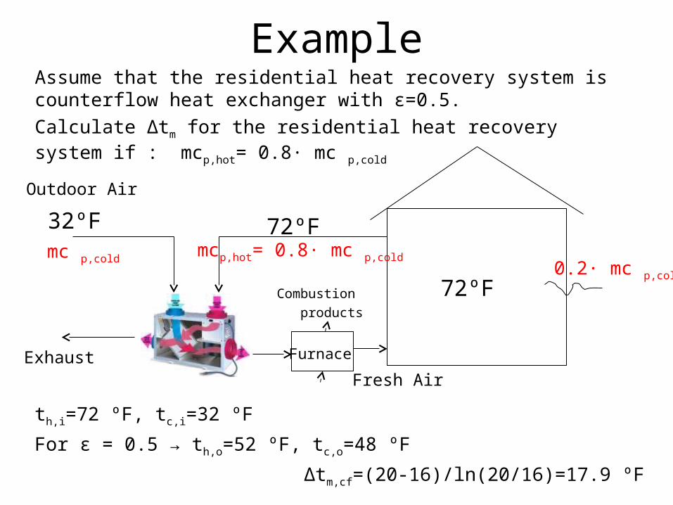
ExampleAssume that the residential heat recovery system is counterflow heat exchanger with ε=0.5.
Calculate Δtm for the residential heat recovery system if : mcp,hot= 0.8· mc p,cold
Furnace
72ºF
32ºF 72ºF
Outdoor Air
Exhaust
Combustion
products
Fresh Air
mcp,hot= 0.8· mc p,cold mc p,cold 0.2· mc p,cold
th,i=72 ºF, tc,i=32 ºF
For ε = 0.5 → th,o=52 ºF, tc,o=48 ºF
Δtm,cf=(20-16)/ln(20/16)=17.9 ºF
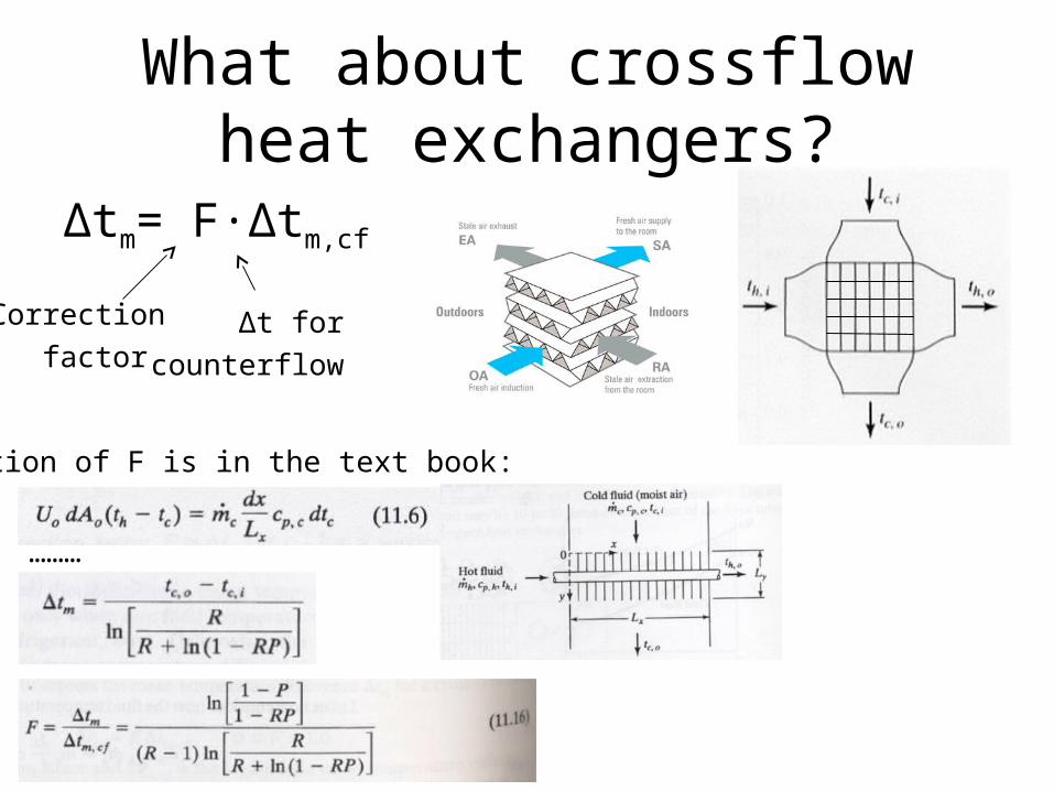
What about crossflow heat exchangers?
Δtm= F·Δtm,cf
Correction
factor Δt for
counterflow
Derivation of F is in the text book:
………
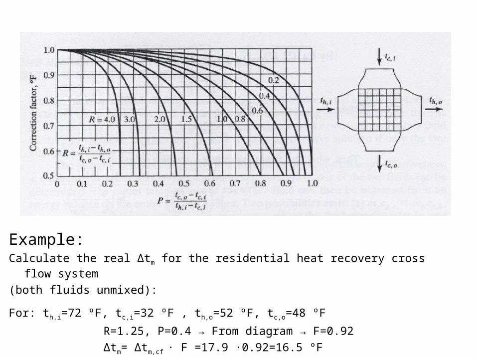
Example:Calculate the real Δtm for the residential heat recovery cross flow system
(both fluids unmixed):
For: th,i=72 ºF, tc,i=32 ºF , th,o=52 ºF, tc,o=48 ºF
R=1.25, P=0.4 → From diagram → F=0.92 Δtm= Δtm,cf · F =17.9 ·0.92=16.5 ºF
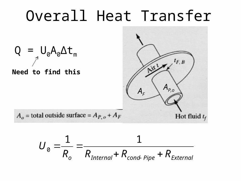
Overall Heat Transfer
Q = U0A0Δtm
ExternalPipecondInternalo RRRRU
110
Need to find this
AP,oAF
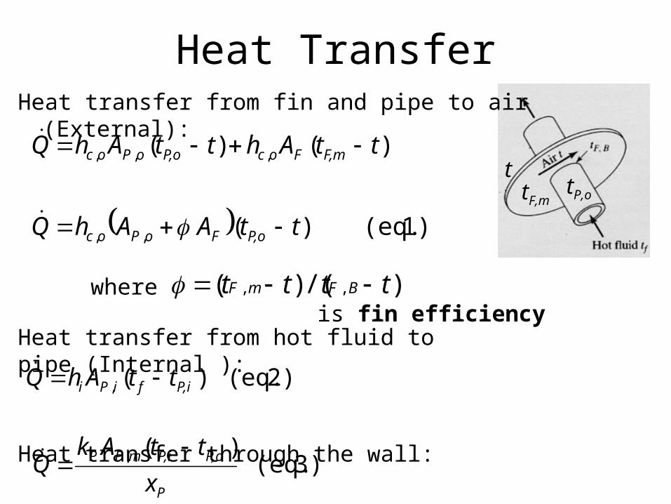
Heat Transfer
tP,o
1) (eq. )(
)()(
,,
,,,
ttAAhQ
ttAhttAhQ
P,oFoPoc
F,mFocP,ooPoc
Heat transfer from fin and pipe to air (External):
tF,m
t
)/()( ,, tttt BFmF where is fin efficiency
Heat transfer from hot fluid to pipe (Internal ):
Heat transfer through the wall:
2) (eq. )(, P,ifiPi ttAhQ
3) (eq. )(,
P
P,oP,imPP
x
ttAkQ
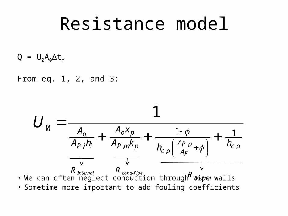
Resistance model
Q = U0A0Δtm
From eq. 1, 2, and 3:
• We can often neglect conduction through pipe walls• Sometime more important to add fouling coefficients
ocFA
oPAoc
pmP
po
iiP
o
hhkA
xA
hAA
U,,
,,,
110
1
R Internal R cond-Pipe R External
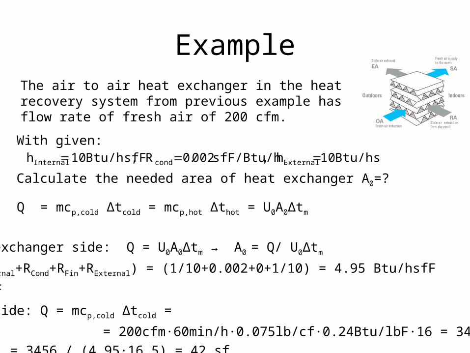
Example
With given:
Calculate the needed area of heat exchanger A0=?
Btu/hsfF 10h ,sfF/Btu/h 002.0R , Btu/hsfF 10 h ExternalcondInternal
The air to air heat exchanger in the heat recovery system from previous example has flow rate of fresh air of 200 cfm.
Solution: Q = mcp,cold Δtcold = mcp,hot Δthot = U0A0Δtm
From heat exchanger side: Q = U0A0Δtm → A0 = Q/ U0Δtm
U0 = 1/(RInternal+RCond+RFin+RExternal) = (1/10+0.002+0+1/10) = 4.95 Btu/hsfF
Δtm = 16.5 F
From air side: Q = mcp,cold Δtcold =
= 200cfm·60min/h·0.075lb/cf·0.24Btu/lbF·16 = 3456 Btu/h
Then: A0 = 3456 / (4.95·16.5) = 42 sf
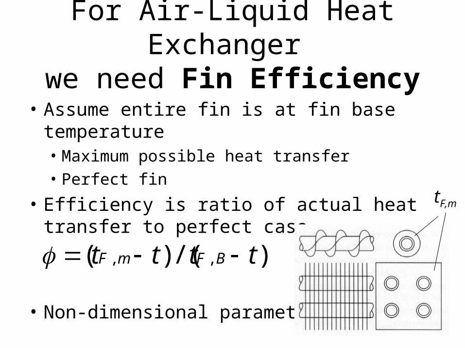
For Air-Liquid Heat Exchanger we need Fin Efficiency
• Assume entire fin is at fin base temperature• Maximum possible heat transfer• Perfect fin
• Efficiency is ratio of actual heat transfer to perfect case
• Non-dimensional parameter
)/()( ,, tttt BFmF
tF,m
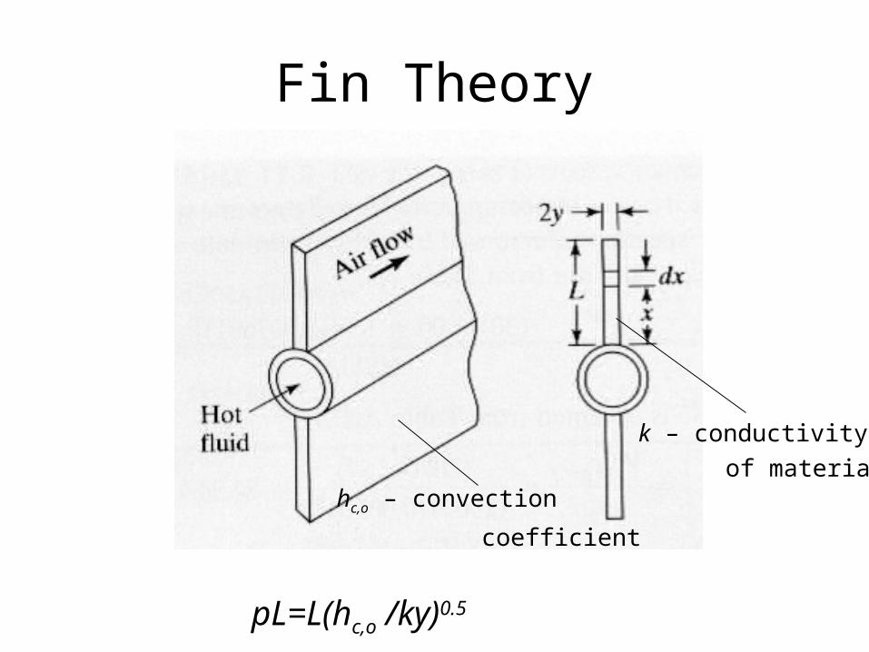
Fin Theory
pL=L(hc,o /ky)0.5
k – conductivity
of material hc,o – convection
coefficient
Reading Assignment
• Chapter 11- From 11.1-11.7

Final project topics
• Beside 3 introduced in last class:• Duct design • DOAS design • VAV design