O 09 0 1 I S cer t i f i e - Testobattery over a longer period. Recharge the battery once per month...
33
testo testo 342 Flue gas analyser Instruction manual testo testo 342-3 °C / °F • O 2 • hPa CO • NO mbar hPa START STOP T O 2 CO 2 CO NO 1 - η E I 0 testo testo TESTO QUALITY Q I S O 9 0 0 1 c e r t i f i e d
Transcript of O 09 0 1 I S cer t i f i e - Testobattery over a longer period. Recharge the battery once per month...
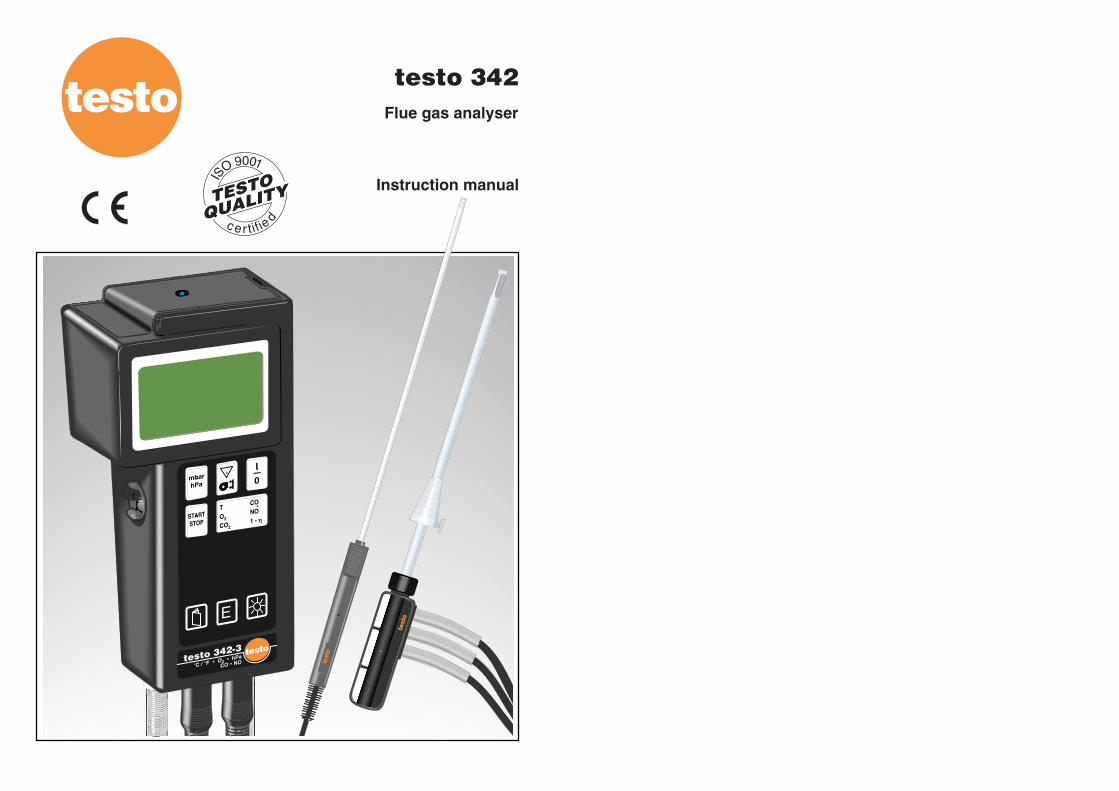
testo testo 342Flue gas analyser
Instruction manual
testotesto 342-3
°C / °F • O2 • hPa
CO • NO
mbarhPa
START
STOP
TO2
CO2
CO
NO
1 - η
E
I
0
test
o
test
o
TESTO
QUALITYQ
IS
O 9001
c e r ti f ie
d

testo Table of contents
2
Table of contents
3
PageMaintenance
Replacing CO measuring cell . . . . . . . . . . . . . . . . . . . . . . . . . . . . . . . . . . . .38Calibration of CO measuring cell with test gas . . . . . . . . . . . . . . . . . . . . . . .39CO recalibration . . . . . . . . . . . . . . . . . . . . . . . . . . . . . . . . . . . . . . . . . . . . . . .41Calibration of CO measuring cell with cell coefficients . . . . . . . . . . . . . . . . .42Replacing an O2 measuring cell . . . . . . . . . . . . . . . . . . . . . . . . . . . . . . . . . . .43Calibration of a new O2 measuring cell . . . . . . . . . . . . . . . . . . . . . . . . . . . . .44Replacing an NO measuring cell . . . . . . . . . . . . . . . . . . . . . . . . . . . . . . . . .46Determining the instrument version . . . . . . . . . . . . . . . . . . . . . . . . . . . . . . . .47
Error messages . . . . . . . . . . . . . . . . . . . . . . . . . . . . . . . . . . . . . . . . . . . . . . . . . .48
Calculation information . . . . . . . . . . . . . . . . . . . . . . . . . . . . . . . . . . . . . . . . . . .51
Technical data/Warranty . . . . . . . . . . . . . . . . . . . . . . . . . . . . . . . . . . . . . . . . . .53
Ordering data . . . . . . . . . . . . . . . . . . . . . . . . . . . . . . . . . . . . . . . . . . . . . . . . . . .55
Option: Infrared printer . . . . . . . . . . . . . . . . . . . . . . . . . . . . . . . . . . . . . . . . . . . .57
Option: Charger . . . . . . . . . . . . . . . . . . . . . . . . . . . . . . . . . . . . . . . . . . . . . . . . . .63
Testo worldwide
PageSystem description . . . . . . . . . . . . . . . . . . . . . . . . . . . . . . . . . . . . . . . . . . . . . . . .4
Instrument description . . . . . . . . . . . . . . . . . . . . . . . . . . . . . . . . . . . . . . . . . . . . .6
Operation instructionsImportant remarks . . . . . . . . . . . . . . . . . . . . . . . . . . . . . . . . . . . . . . . . . . . . . . .7Power supply . . . . . . . . . . . . . . . . . . . . . . . . . . . . . . . . . . . . . . . . . . . . . . . . . .8Connection of probes . . . . . . . . . . . . . . . . . . . . . . . . . . . . . . . . . . . . . . . . . . .10- Condensate trap . . . . . . . . . . . . . . . . . . . . . . . . . . . . . . . . . . . . . . . . . . . . . .11- Holding fixture (accessories) . . . . . . . . . . . . . . . . . . . . . . . . . . . . . . . . . . . .12
User instructions Temperature, O2/CO2/CO and NO measurement . . . . . . . . . . . . . . . . . . . . .13Draught measurement . . . . . . . . . . . . . . . . . . . . . . . . . . . . . . . . . . . . . . . . . .15Gas pressure measurement . . . . . . . . . . . . . . . . . . . . . . . . . . . . . . . . . . . . . .17Temperature measurement . . . . . . . . . . . . . . . . . . . . . . . . . . . . . . . . . . . . . .18Illuminated LCD display . . . . . . . . . . . . . . . . . . . . . . . . . . . . . . . . . . . . . . . . .19Switching-off the instrument . . . . . . . . . . . . . . . . . . . . . . . . . . . . . . . . . . . . . .19
Short guide to MEASURING and PRINTING . . . . . . . . . . . . . . . . . . . . . . . . . . . . .20
FUEL selection . . . . . . . . . . . . . . . . . . . . . . . . . . . . . . . . . . . . . . . . . . . . . . . . . . .22
CORRECTION menuCorrecting the ambient air temperature . . . . . . . . . . . . . . . . . . . . . . . . . . . . .23Setting an O2 reference value . . . . . . . . . . . . . . . . . . . . . . . . . . . . . . . . . . . . .24User fuel . . . . . . . . . . . . . . . . . . . . . . . . . . . . . . . . . . . . . . . . . . . . . . . . . . . . .25
SERVICE menuOperational values . . . . . . . . . . . . . . . . . . . . . . . . . . . . . . . . . . . . . . . . . . . . .26Units of measurement . . . . . . . . . . . . . . . . . . . . . . . . . . . . . . . . . . . . . . . . . . .27Calibration . . . . . . . . . . . . . . . . . . . . . . . . . . . . . . . . . . . . . . . . . . . . . . . . . . . .28Order of indication . . . . . . . . . . . . . . . . . . . . . . . . . . . . . . . . . . . . . . . . . . . . . .30(Protective) disconnection . . . . . . . . . . . . . . . . . . . . . . . . . . . . . . . . . . . . . . . .32Recalibration . . . . . . . . . . . . . . . . . . . . . . . . . . . . . . . . . . . . . . . . . . . . . . . . . .34Setting/changing the printing text . . . . . . . . . . . . . . . . . . . . . . . . . . . . . . . . . .35Date and time . . . . . . . . . . . . . . . . . . . . . . . . . . . . . . . . . . . . . . . . . . . . . . . . .36
Printout on infrared printer . . . . . . . . . . . . . . . . . . . . . . . . . . . . . . . . . . . . .37
Measuring instrument conformswith EN 50 082-1 / EN 55 011 Group 1 Class A

testo System description
4
Description
Gas path
5
������
����
���
���
��� PCapillaries
PC
MC�CO
MC�O2
p
T/FT
testo® 342testoterm
T/AT
Fine filterCondensate trap�with filter
Exit
Gas
Draught
FGP
FG
MC�NO
testoterm
FG = Flue gasPC = Pre-combustion chamberMC = Measuring chamberT/AT = Ambient temperatureT/FT = Flue gas temperature
testo 342 was developed for domestic and heavyindustrial applications. It enables the simple andprecise measurement and control of flue gastemperature, ambient temperature, oxygen content,CO2 and CO content (not testo 342-2), draught,excess air, Efficiency Gross/Net and NO content(not testo 342-1).
All measured data can be transferred to the optionalprinter via the integrated infrared interface, printedand thus recorded.
The testo 342 is available in the following versions:
testo 342-1 with O2 and CO measuring cellstesto 342-2 with O2 and NO measuring cellstesto 342-3 with O2, CO and NO measuring cells
These products are mainly aimed at service engineers,heating technicians and engineers with advanced know-ledge and experience in everyday measuringtechnology.We except those trained in measuring technology to beable to recognise differences from the standardconditions and to be able to assess their effect on themeasurement result. The following instructions shouldbe of some help.
testo Instrument description
6
testo 342-3°C / °F • O2
• hPaCO • NO
mbarhPa I
O
STARTSTOP
TO2
CO2
CONO
1 - η
E
testo
Operation instructions
Important remarks
Charge the built-in rechargeable battery fully before the first measurementor after a break of several days (see display of battery life during cali-
bration phase). Should the instrument not be used for long periods,recharge the rechargeable battery every 4 weeks to avoid a complete
drainage.
Operation via mains unit Only use the original mains unit for operating the instrument.
Flue gas probesOnly flue gas probes with integrated condensate trap can be connected directlyto the testo 342. Should a probe without integrated filter and condensate unitbe connected, instrument failure will occur.
TightnessBefore a measurement is started, the complete measuring system (probe, condensate trap, tubes and screwings) must be tested for tightness. Shouldthere be air leaks, the results of the measurement may be incorrrect.
Gas exitEnsure that the gas exit of the analyser is uncovered during measurement, sothat the gas can escape unhindered. The results of the measurement may otherwise be incorrect.
Condensate trapThe condensate trap may only be emptied when the pump is switched off (the measuring cells are otherwise at risk)!
Measuring cellsSmall amounts of concentrated acids are contained in the measuring cells(except for in the O2 sensor electrolyte) and should, thus, be treated as special waste (like commercial batteries).
Functions of the keyboardThe turnover key always enables the user to jump into or backwards within themenus. The Enter key confirms the option selected in the main menus, and inany function it enables you to jump to the next setting. The Burner/Down keymoves the cursor down in the main menu and changes the figures in the function menus.
7
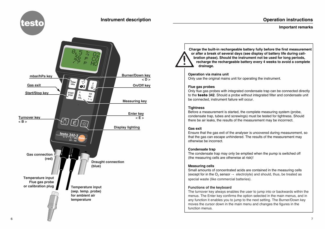
Start/Stop key
mbar/hPa key Burner/Down key< D >
Measuring key
Display lighting
Turnover key< B >
Enter key< E >
On/Off key
Gas connection(red)
Temperature inputFlue gas probe
or calibration plug
Draught connection(blue)
Temperature input(sep. temp. probe)for ambient airtemperature
Gas exit
testo Operation instructions
8
Operation instructions
Power supplyPower supply
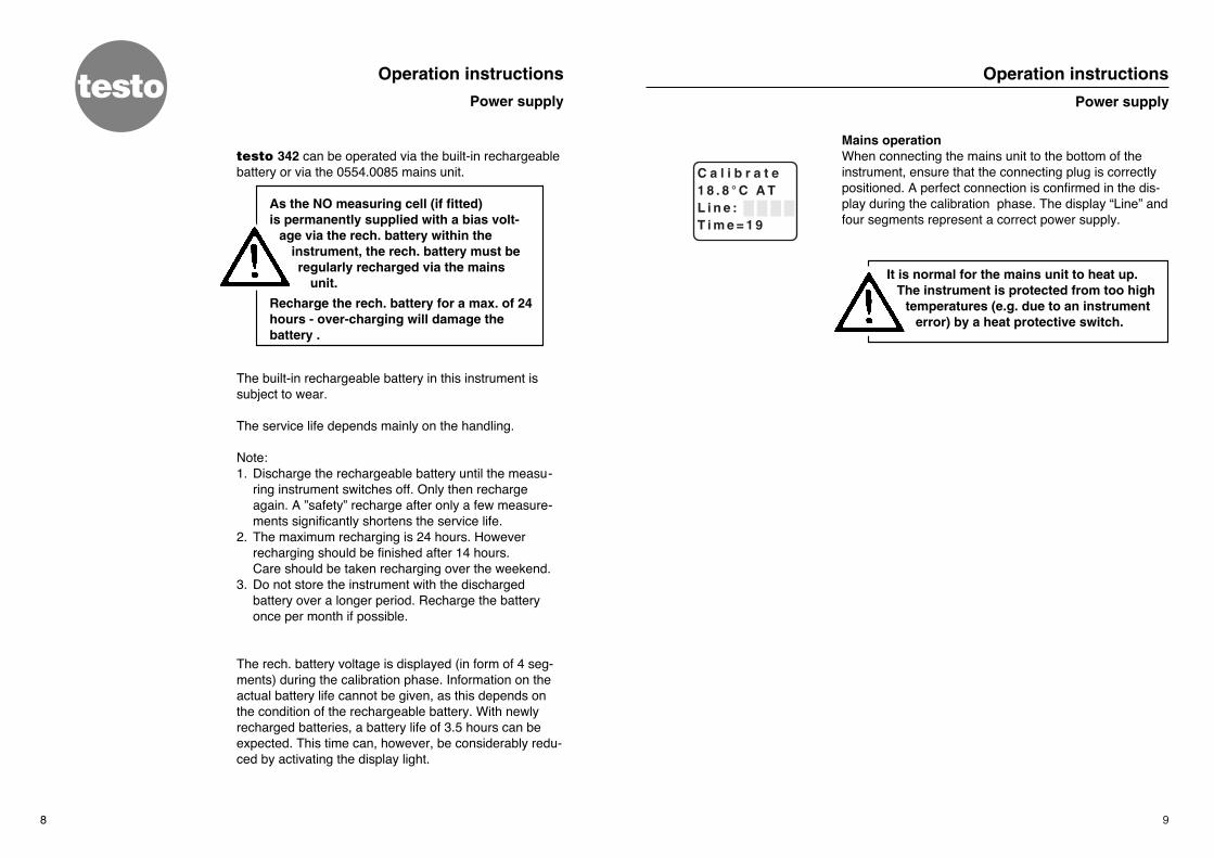
Mains operationWhen connecting the mains unit to the bottom of theinstrument, ensure that the connecting plug is correctlypositioned. A perfect connection is confirmed in the dis-play during the calibration phase. The display “Line” andfour segments represent a correct power supply.
It is normal for the mains unit to heat up. The instrument is protected from too high
temperatures (e.g. due to an instrumenterror) by a heat protective switch.
9
C a l i b r a t e1 8 . 8 ° C A TL i n e :T i m e = 1 9
testo 342 can be operated via the built-in rechargeablebattery or via the 0554.0085 mains unit.
The built-in rechargeable battery in this instrument issubject to wear.
The service life depends mainly on the handling.
Note:1. Discharge the rechargeable battery until the measu-
ring instrument switches off. Only then recharge again. A ”safety” recharge after only a few measure-ments significantly shortens the service life.
2. The maximum recharging is 24 hours. However recharging should be finished after 14 hours. Care should be taken recharging over the weekend.
3. Do not store the instrument with the discharged battery over a longer period. Recharge the battery once per month if possible.
The rech. battery voltage is displayed (in form of 4 seg-ments) during the calibration phase. Information on theactual battery life cannot be given, as this depends onthe condition of the rechargeable battery. With newlyrecharged batteries, a battery life of 3.5 hours can beexpected. This time can, however, be considerably redu-ced by activating the display light.
As the NO measuring cell (if fitted) is permanently supplied with a bias volt-
age via the rech. battery within theinstrument, the rech. battery must beregularly recharged via the mains
unit.
Recharge the rech. battery for a max. of 24hours - over-charging will damage thebattery .
testo Operation instructions
Connection of probes
10
testo
Operation instructionsCondensate trap
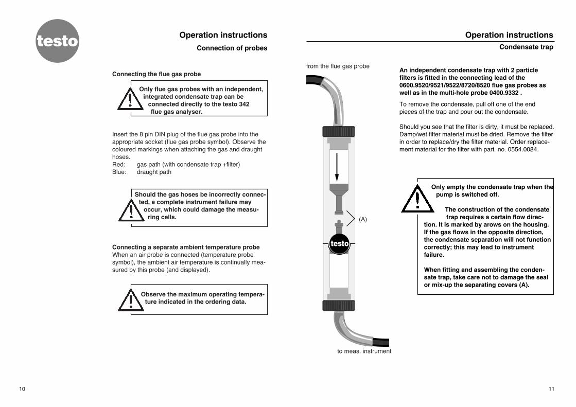
An independent condensate trap with 2 particlefilters is fitted in the connecting lead of the0600.9520/9521/9522/8720/8520 flue gas probes aswell as in the multi-hole probe 0400.9332 .
To remove the condensate, pull off one of the end pieces of the trap and pour out the condensate.
Should you see that the filter is dirty, it must be replaced.Damp/wet filter material must be dried. Remove the filterin order to replace/dry the filter material. Order replace-ment material for the filter with part. no. 0554.0084.
Only empty the condensate trap when thepump is switched off.
The construction of the condensatetrap requires a certain flow direc-
tion. It is marked by arows on the housing.If the gas flows in the opposite direction,the condensate separation will not functioncorrectly; this may lead to instrumentfailure.
When fitting and assembling the conden-sate trap, take care not to damage the sealor mix-up the separating covers (A).
11
(A)
from the flue gas probe
to meas. instrument
Connecting the flue gas probe
Insert the 8 pin DIN plug of the flue gas probe into theappropriate socket (flue gas probe symbol). Observe thecoloured markings when attaching the gas and draughthoses.Red: gas path (with condensate trap +filter)Blue: draught path
Connecting a separate ambient temperature probeWhen an air probe is connected (temperature probesymbol), the ambient air temperature is continually mea-sured by this probe (and displayed).
Should the gas hoses be incorrectly connec-ted, a complete instrument failure may
occur, which could damage the measu-ring cells.
Only flue gas probes with an independent,integrated condensate trap can be
connected directly to the testo 342 flue gas analyser.
Observe the maximum operating tempera-ture indicated in the ordering data.

Temperature, O2/CO2/CO and NO measuremente.g. for the setting of burners
13
testo
12
User instructions
Switch on the measuring instrument (the flue gas probeis in fresh air).
The instrument jumps to the calibration phase(duration: approx. 70 seconds).
The O2 cell must be adjusted to read 21.0%. By pressing the burner key, the flashing digit can beadjusted. Activate the next digit by pressinf Enter andadjust with the burner key.
The instrument jumps to the sub-menu “fuel selection”.
You can select the required fuel with the burner key. The cursor indicates which fuel is selected.
Press the measuring key in order to jump to themeasurement.
Insert the flue gas probe into the flue.
I
O
C a l i b r a t e1 8 . 8 ° C A TA c c u :T i m e = 1 9
testoterm
N a t u r . g a s2 5 . 0 ° C F T2 1 . 0 % O 2
N a t u r . g a sL i g h t o i lH e a v y o i lC o a l
N a t u r . g a sL i g h t o i lH e a v y o i lC o a l
O 2 c e l lc a l i b r a t ea d j u s tO 2 = 2 1 . 0 %
TO2
CO2
CONO1 - η
Operation instructions
Option: Holding fixture
• Attach the fixing device with direction-finder and magnets (holding fixture) at the extraction point (feed the direction-finder into the drilled hole).
• Secure the holding device for the flue gas probe by means of the holding belt.
• Withdraw the direction-finder and insert the flue gas probe in such a way that the protective frame at the tip of the flue gas probe is situated across the direction of the gas flow. When the locking lever is open, the flue gas probe can be moved in the gas pipe. If the flue gas probe is situated in the core flow, it should be fixed with the locking lever.
• When fixing the flue gas probe, make sure that the tipof the probe is on the same level or a little higher thanthe handle of the flue gas probe. You can, thus, avoidgetting moisture on the thermocouple, which would lead to incorrect measuring results.
testoTemperature, O2/CO2/CO and NO measurement
e.g. for the setting of burners
User instructions
1514
User instructions
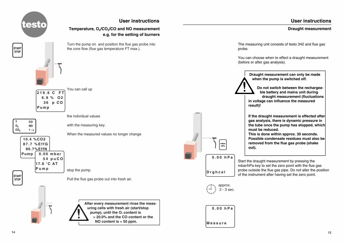
Draught measurement
The measuring unit consists of testo 342 and flue gasprobe.
You can choose when to effect a draught measurement(before or after gas analysis).
Start the draught measurement by pressing thembar/hPa key to set the zero point with the flue gasprobe outside the flue gas pipe. Do not alter the positionof the instrument after having set the zero point.
Draught measurement can only be madewhen the pump is switched off.
Do not switch between the rechargea-ble battery and mains unit duringdraught measurement (fluctuations
in voltage can influence the measuredresult)!
If the draught measurement is effected aftergas analysis, there is dynamic pressure inthe tube once the pump has stopped, whichmust be reduced.This is done within approx. 30 seconds.Possible condensate residues must also beremoved from the flue gas probe (shakeout).
testoterm
mbarhPa
approx.2 - 3 sec.
0 . 0 0 h P a
D r g h c a l
0 . 0 0 h P a
M e a s u r e
10.4 %CO28 7 . 7 % E f f G
96.7%EffNPump
Turn the pump on and position the flue gas probe intothe core flow (flue gas temperature FT max.).
You can call up
the individual values
with the measuring key.
When the measured values no longer change
stop the pump.
Pull the flue gas probe out into fresh air.
STARTSTOP
STARTSTOP
testoterm
testoterm
2 1 9 . 6 C F T6 . 9 % O 23 6 p C O
P u m p
TO2
CO2
CONO1 - η
After every measurement rinse the meas-uring cells with fresh air (start/stop
pump), until the O2 content is> 20.0% and the CO content or theNO content is < 50 ppm.
0 . 0 0 m b a r5 4 p u C O
17.8 °C ATP u m p

Gas pressure measurementtesto User instructions
1716
User instructions
When adjusting gas installations the testo 342 can beused for gas pressure measurement. Attach a piece ofhose pipe between the gas pipe and the hand-heldinstrument testo 342. Use the input marked with a blue point. For a pressure tight connection to the hand-held instrument a nipple can be screwed on (order no. 0400.9023).
1) Remove the (draught) hose pipe of theflue gas probe from the instrument.
2) Reset to zero by pressing the mbar key. 3) Connect the hose for the gas pressure measurement.4) Pressure measurement is running (- = excess pressure)
When the measured values have stabilised, end thedraught measurement.
5) The value is now saved and can only be reset to zeroby repeatedly pressing the mbar/hPakey.
testo 342-3°C / °F • O2
• hPaCO • NO
η
testo
testo 342-3°C / °F • O2
• hPaCO • NO
η
testo
mbarhPa 0 . 0 0 h P a
D r g h c a l
- 5 . 2 0 h P a
D r g h c a l
1
2
mbarhPa 5 . 2 0 h P a
F i n i s h d
5
3
4
Do not use in the main connection.
Ensure that the path between the sampling pointand the measuring instrument is tightly sealed
(escaping gas and oxygen could form an explosivemixture)
Do not smoke when measuring. Use of naked flameshould be avoided.
Observe the nominal pressure at the connection! It must not exceed 40 hPa!
Gas cannot get into the measuring instrumentbecause an air cushion is formed between the sen-sor and the gas inlet. For this reason the measuring
device is not explosion-proof.
Draught measurement
Insert the flue gas probe into the gas pipe.
When the measured values have stabilised, end thedraught measurement.
The value is now saved and can be reset to zero byrepeatedly pressing the mbar/hPa key.
testoterm
0 . 1 5 h P a
M e a s u r e
0 . 1 5 h P a
F i n i s h d
mbarhPa
Do not measure for longer than 5 minutes, then startagain from Point 2 ( reset to zero). Otherwise themeasured values could be outside the tolerance
level on account of drift.

User instructions
Illuminating the LCD/Switching off the instrument
The display can be illuminated by pressing the key.As the light consumes a lot of power, it switches off auto-matically after 3 minutes, so as to protect the rechargea-ble batteries.It can be switched back on by pressing thekey again.
Switching off the instrumentWhen the on/off key is pressed, “Instrument will switchoff” is displayed. In the 5 seconds that follow, you canpress any key (apart from ON/OFF to return to the lastmenu.
If no key is pressed, the instrument switches itself off.
If the instrument detects too high concentrations of gasin the cells, it will ask you to rinse them with fresh air.Place the flue gas probe in fresh air and start the pumpwith ENTER.
Should you avoid this rinsing phase (by pressing theon/off key again), the measuring instrument will repeatthe calibration phase several times when it is switchedback on.
The concentrations of gas are displayed in the rinsingmode. If the concentrations of gas have reduced to thelimit values, the instrument automatically switches itselfoff.
19
I n s t r u m e n tw i l ls w i t c h o f fs o o n
R i n s eb e f o r es w i t c h i n go f f S t a r t
r i n s i n gw i t h< E > k e y
R i n s i n g2 1 . 0 % O 2
7 8 p C O6 3 p N O
testoTemperature measurement
If you only want to take a temperature measurement,connect 2 temperature probes and press the start/stopkey to start (or to stop) the measurement.
The FT temperature value corresponds to temperatureprobe 1, AT corresponds to temperature probe 2.
User instructions
18
testotesto 342-3
°C / °F • O2 • hPa
CO • NO
mbarhPa
START
STOP
TO2
CO2
CO
NO
1 - η
E
I
0
Temp.-Fühler 2� VT
Temp.-Fühler 1� AT
Temp.probe 2 AT
Temp. probe 1 FT

8.Infrared printer
21
testo
20
Select main menu
Press printing modepump stopsmeasured values are held in display
Printingmode is
interrupted
P r i n t . . . . . . .F u e l . . . . . . . .C o r r e c t i o nS e r v i c e . . .
M e a s u r e dv a l u e s a r eb e i n gp r i n t e d
2 1 9 . 6 ° C F T6 . 9 % O 2
3 6 p C O
1 0 . 4 % C O 28 7 . 7 % E f f G9 6 . 7 % E f f N
2 p N O
TO2
CO2
CONO1 - η
TO2
CO2
CONO1 - η
STARTSTOP
0 . 0 0 m b a r5 4 p C O
1 7 . 8 % A T
2 1 . 6 ° C F T2 0 . 9 % O 2
8 p C O
TO2
CO2
CONO1 - η
TO2
CO2
CONO1 - η
ME
AS
UR
EM
ain m
enu
PR
INTP r i n t i n g
h a s b e e ni n t e r -r u p t e d
E
E
E
Short guide to “MEASURING” and “Printing” Short guide to “MEASURING” and “Printing”
I
O
N a t u r . g a sL i g h t o i lH e a v y o i lC o a l
N a t u r . g a sL i g h t o i lH e a v y o i lC o a l
Cal
ibra
tion
ph
ase
Fu
el s
elec
tio
nS
etti
ng
th
e O
2se
t va
lue
4. Move cursor to the required fuel.
1. Switch on
5. Select measurement menu
6. Place flue gas probe in the flue gas, start the pump, look for the core flow, call up the measured values
7. Stop the pump,remove the flue gas probe from the flue gas
TO2
CO2
CONO1 - η
TO2
CO2
CONO1 - η
N a t u r . g a sL i g h t o i lH e a v y o i lC o a l
C a l i b r a t e1 8 . 8 ° C V TA c c u :T i m e = 1 9
U s e r - F u e l A n t h r a c i t eC o k eP r o p a n eB u t a n e
2. Wait for the calibration phase
3. Setting the O2.set value
Set the O2 value to 20.9%
O 2 C e l lC a l i b r a t ea d j u s tO 2 = 1 9 . 8 %
O 2 C e l lC a l i b r a t ea d j u s tO 2 = 1 9 . 9 %
O 2 C e l lC a l i b r a t ea d j u s tO 2 = 1 9 . 9 %
O 2 C e l lC a l i b r a t ea d j u s tO 2 = 1 0 . 9 %
O 2 C e l lC a l i b r a t ea d j u s tO 2 = 1 0 . 9 %
O 2 C e l lC a l i b r a t ea d j u s tO 2 = 2 0 . 9 %

CORRECTION menu
Correcting the ambient air temperature
23
testo Fuel selection
22
If a separate temperature probe is used e.g. 0610.9713,the ambient temperature AT is continuously measuredby this temperature probe as soon as it is plugged-in andthe efficiency is continuously calculated. The values lastdisplayed remain stored after the probe has been unplugged.
Main
men
uS
ub
men
u
C o r r e c t i o na m b i e n ta i r t e m p .2 0 . 8 ° C A T
E
Select the correction menu
1 0 . 4 % C O 28 7 . 7 % E f f G9 6 . 7 % E f f N
When using the flue gas probe for measuringthe ambient air temperature, switch the pump
off and let the flue gas probe cool down before measuring the temperature in theburner air intake.
TO2
CO2
CONO1 - η
E
P r i n t . . . . . .F u e l . . . . . . .C o r r e c t i o nS e r v i c e . . .
C o r r e c t A TO 2 - R e f .U s e r - F u e l
Store adjust-ments.
Mai
n m
enu
Su
bm
enu N a t u r . g a s
L i g h t o i lH e a v y o i lC o a l
EActivate fuel selection
The most common fuels are stored with their characteristic values:
Fuel CO2max Kgr Knet K1 O2bz Hydrogen Moisture Qgr Qnet
Content of Content % ---- ---- ---- % Fuel of Fuel
H % MH2O % mJ/kg mJ/kg Natural gas 11.9 0.35 0.39 40 3 24.4 0.0 53.42 48.16 Light oil 15.5 0.48 0.51 53 3 13.0 0.0 45.60 42.80Heavy oil 15.8 0.51 0.54 54 3 11.5 0.2 42.90 40.50Coal 18.4 0.62 0.65 63 7 4.0 13.0 26.75 25.50Anthracite 19.1 0.67 0.69 65 3 3.0 12.0 29.65 28.95Coke 20.6 0.75 0.76 70 7 0.4 10.0 27.90 27.45Propane 13.8 0.42 0.45 48 3 18.2 0.0 50.00 46.30Butane 14.1 0.43 0.46 48 3 17.2 0.0 49.30 45.80User-fuel* 11.9 0.35 0.39 40 3 24.2 0.0 53.42 48.16
The last acknowledged fuel remains stored even after switching off the instrument.
* default-values may be changed by user
A n t h r a c i t eC o k eP r o p a n eB u t a n e
TO2
CO2
CONO1 - η
Store adjustments
P r i n t . . . . . .F u e l . . . . . . .C o r r e c t i o nS e r v i c e . . .
U s e r - F u e l

CORRECTION menu
User fuel
25
C O 2 M = 1 1 . 9K g r = 0 . 3 5 0K n e t = 0 . 3 9 0K 1 = 4 0
The special characteristic values of the user fuel in usecan be stored in the measuring instrument.
A maximum value of 255 is valid for CO2max and K1.
EConfirm the menu mode
Su
bm
enu
C O 2 M = 2 1 . 9K g r = 0 . 3 5 0K n e t = 0 . 3 9 0K 1 = 4 0
TO2
CO2
CONO1 - η
C o r r e c t A TO 2 - R e f .U s e r - F u e l
C O 2 M = 1 1 . 9K g r = 0 . 3 5 0K n e t = 0 . 3 9 0K 1 = 4 0
Store adjustments
E
Q g r = 5 5 . 4 2Q n e t = 4 8 . 1 6X = 2 1 9 . 6
C O 2 M = 1 1 . 9K g r = 0 . 3 5 0K n e t = 0 . 3 9 0K 1 = 4 0
testoSetting an O2 reference value
CORRECTION menu
24
The O2 reference value is required for the conversion ofthe ppm values to mg/m3. This can be individually selec-ted and stored for each fuel. The O2 reference value isdisplayed with the mg/m3 display. It is freely adjustable inthe range 0 to 21%.
The figure can be changed with the Down key.
Your alterations are stored with the measuring key. Youwill automatically find yourself in the measurementmenu.
EConfirm the menu mode
Select O2 reference value
N a t u r . g a sO 2 - R e f .
= 6 %
Heavy oilO2-Ref.
= 3%
TO2
CO2
CONO1 - η
E
C o r r e c t A TO 2 - R e f .U s e r - F u e l
Light oilO2-Ref.
= 3%Select fuel
Store adjustments
N a t u r . g a sO 2 - R e f .
= 6 %
N a t u r . g a sO 2 - R e f .
= 7 %
Su
bm
enu

"Service" menu
Units of measurement
27
testo "Service" menu
Operational values
In this submenu, data necessary for ensuring that theinstrument functions perfectly, is displayed.
26
It is possible to choose between two measuring units fora measured variable:
° C ° Fppm mg/m3
(The indication mg/m3 refersto dry gas in normal state: 0 ° C, 1013 mbar air pressure).
hPa mbar
The cursor jumps to the next row with the Enter key andyou can alter the unit of measurement with the Downkey.
The adjustments are stored by pressing the measuringkey. You will automatically find yourself in the measure-ment menu.
Un
its of m
eas.S
ervice-men
u
Temp . CGas p pmDrght hP a
Confirm fuel selection
TO2
CO2
CONO1 - η
Store adjustments
Temp . CGas p pmDrght hP aE
I n s t r . s t a tM e a s . v a rC a l i b r a t eI n d i c . o r d .
Temp . CGas mgDrght hP a
E
Ser
vice
-men
u I n s t r . s t a tM e a s . v a rC a l i b r a t eI n d i c . o r d .
Op
. val
ues
2 2 . 4 °C DT1 1 . 5 V VI
Confirm selection
Return tomeasurementmenu
TO2
CO2
CONO1 - η
Please observe the permissible operatingtemperature +4 to +40 ° C
(+40 to +105°F).
The instrument does not leave thecalibration phase for the measurementmenu at temperatures below +4°C (+40°F)(the error message: “IT?” appears).
E
"Service" menu
Calibration
29
testo "Service" menu
Calibration
28
E
E E
C O - C e l lN O - C e l l
C O - C e l lN O - C e l l
B = + 0 . 6 7 5 1F = + 1 . 3 7 1 4E = + 0 . 4 2 1 3C = + 2 . 2 0 9 7
E n t e r t h e a m b i e n tt e m p2 0 . 0 ° C
G a s c a l i b .E n t e r c o d e
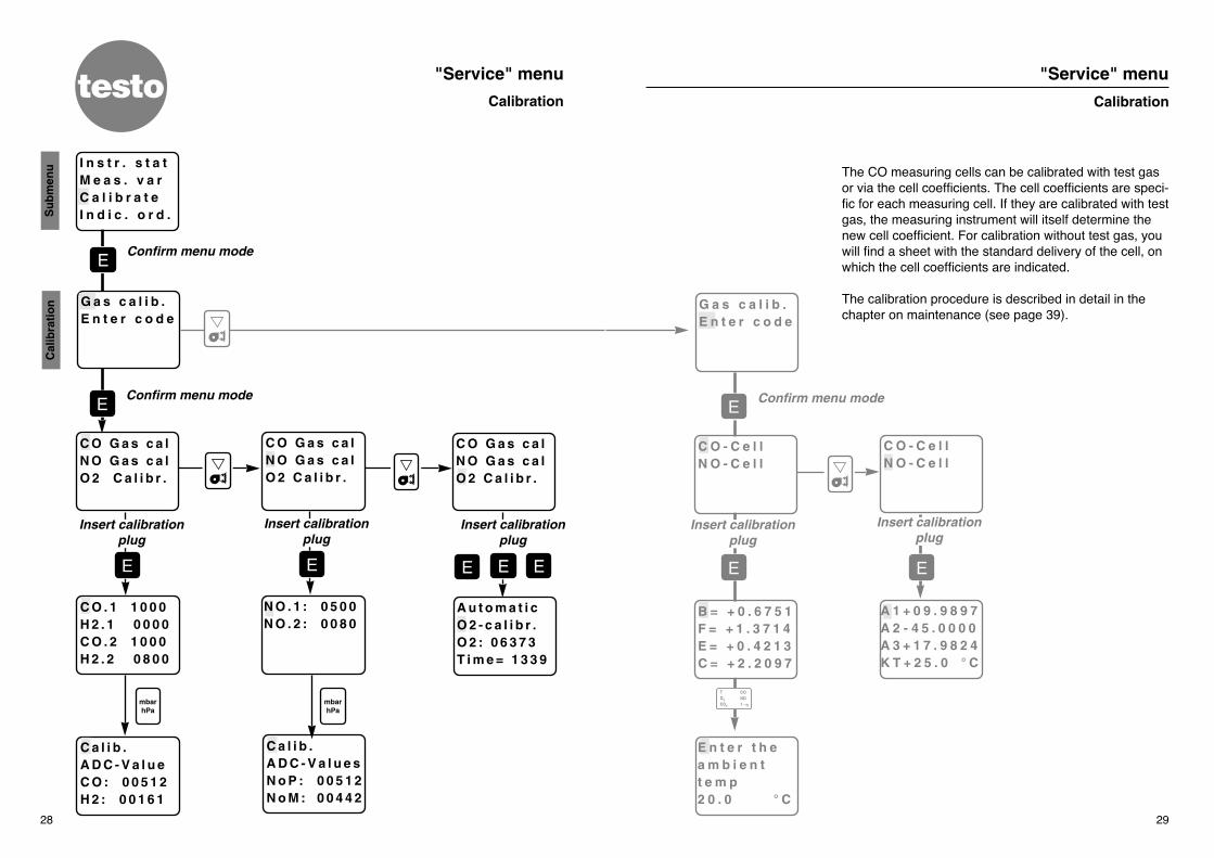
The CO measuring cells can be calibrated with test gasor via the cell coefficients. The cell coefficients are speci-fic for each measuring cell. If they are calibrated with testgas, the measuring instrument will itself determine thenew cell coefficient. For calibration without test gas, youwill find a sheet with the standard delivery of the cell, onwhich the cell coefficients are indicated.
The calibration procedure is described in detail in thechapter on maintenance (see page 39).
A 1 + 0 9 . 9 8 9 7A 2 - 4 5 . 0 0 0 0A 3 + 1 7 . 9 8 2 4K T + 2 5 . 0 ° C
Insert calibrationplug
Insert calibrationplug
Confirm menu mode
EConfirm menu mode
Confirm menu mode
Su
bm
enu
Cal
ibra
tio
n G a s c a l i b .E n t e r c o d e
E
I n s t r . s t a tM e a s . v a rC a l i b r a t eI n d i c . o r d .
C O G a s c a lN O G a s c a lO 2 C a l i b r .
C O G a s c a lN O G a s c a lO 2 C a l i b r .
C O . 1 1 0 0 0H 2 . 1 0 0 0 0C O . 2 1 0 0 0H 2 . 2 0 8 0 0
C a l i b .A D C - V a l u eC O : 0 0 5 1 2H 2 : 0 0 1 6 1
C a l i b .A D C - V a l u e sN o P : 0 0 5 1 2N o M : 0 0 4 4 2
A u t o m a t i cO 2 - c a l i b r .O 2 : 0 6 3 7 3T i m e = 1 3 3 9
C O G a s c a lN O G a s c a lO 2 C a l i b r .
N O . 1 : 0 5 0 0N O . 2 : 0 0 8 0
Insert calibration plug
Insert calibrationplug
Insert calibrationplug
E E EE E
mbarhPa
mbarhPa
TO2
CO2
CONO1 - η

"Service" menu
Order of indication
You can adjust the order of indication within a block ofmeasured values according to your needs.
Each block of measured values contains the followingvariables:- selected fuel- flue gas temperature FT- ambient temperature - O2 content- CO2 content- Efficiency Gross- Efficiency Net- excess air- draught- CO content- uCO- NO content- O2 reference- Ratio (rat)- You can also produce empty lines
The adjustments can be stored by pressing the measu-ring key (and remain stored even after the measuringinstrument has been switched off).
31
testo "Service" menu
Order of indication
30
Ser
vice
men
uO
rder
of
ind
.
1 . Fuel2 . FT3 . AT
4 . O25 . CO26 . EffG
13. O2 Ref .14. rat15 . - - - - - - -
1 . FT2 . FT3 . AT
10. C O1 1 . u C O12 . N O
7 . EffN8. λ9 . Draught
Confirm the menu mode
Change theorder of indication
Store adjustments
I n s t r . s t a tM e a s . v a rC a l i b r a t eI n d i c . o r d .
E
TO2
CO2
CONO1 - η
EE
E
EE
E
EE
EE
EE

"Service" menu
Disconnection
33
testo "Service" menu
Disconnection
32
E
In order to protect the NO measuring cells, the pumpswitches off at concentrations of above 3000 ppm. Thisis a factory setting.
The limit value setting is freely selectable within therange 1000 to 3900 ppm (in steps of 100).
Even when a limit value of 0000 ppm is set, the protec-tive function remains. The pump will switch off in NOconcentrations of ≥ 4000 pm.
If the pump has switched itself off (“Rinsing”appears in the display), remove the flue gas probefrom the flue gas and rinse the measuring cells withfresh air.
Each time the pump switches off automatically, werecommend that you rinse the measuring cells withfresh air until the CO value or NO value drops below50 ppm CO (or 50 ppm NO).
TO2
CO2
CONO1 - η
M e a s u r e m .t u r n o f fa t 3 2 0 0p p m
Store adjustments.
M e a s u r e m .t u r n o f fa t 2 2 0 0p p m
CO - Cel lNO - Cel l
Only continue the measurement if it isabsolutely necessary.
Confirm the measurement mode
Ser
vice
men
uD
isco
nn
ecti
on
CO - Cel lNO - Cel l
E
I n s t r . s t a tM e a s . v a rC a l i b r a t eI n d i c . o r d .
Measurem.turn offat 4 0 0 0ppm
The pump automatically switches itself off at high con-centrations of CO in order to protect the CO measuringcell.
The meas. instrument has been adjusted by the manu-facturer in such a way that the pump automatically stopswhen measurements are performed in concentrations ofmore than 4000 ppm. This limit value can be adjustedover the range 2.000 to 7.000 ppm (in steps of 1000).
Even when this protection is switched off (by setting alimit value of 0000 ppm), a certain protective functionremains. The pump switches itself off in CO concen-trations of ≥ 8100 ppm.
TO2
CO2
CONO1 - η
Store adjustments
M e a s u r e m .t u r n o f fa t 4 0 0 0p p m
S w i t c h o f fR e c a l i b r .P r i n t - T e x tT i m e / D a t e
E

Print text menu
Setting/changing the printing text
35
testo "Service" menu
Recalibration
34
Prin
ting
textS
ervice-men
u
T e s t oL t d .
1 s t l i n e
Confirm selection
Call up thesecond line
I n s t r . s t a tM e a s . v a rC a l i b r a t eI n d i c . o r d .
E m s w o r t h ,H a n t s ,P O 1 0 7 B T2 n d l i n e
Two lines of 24 characters are available as printed text.This text is printed as a headline on every measuringprotocol that you print.
The mbar/hPa key enables you to choose between capitol and small letters and to call up special charac-ters.
The adjustments can be stored by pressing the measu-ring key (and remain stored when the measuring instru-ment is switched off). You will automatically return to themeasurement menu.
U e s t oL t d .
1 s t l i n e
E
U e s t oL t d .
1 s t l i n e
E
TO2
CO2
CONO1 - η
Store adjust-ments
S w i t c h o f fR e c a l i b r .P r i n t T e x tT i m e / D a t e
E Confirm menu mode
Ser
vice
mn
euR
ecal
ibra
tio
n
C O - C e l lN O - C e l l
I n s t r . s t a tM e a s . v a rC a l i b r a t eI n d i c . o r d .
You have a NO or CO reference value due to the pre-sence of a test gas or reference instrument. This valuecan be used to inform the instrument of a correction factor for the measurement of (NO) CO. The instrumentthen calculates the exact (NO) CO values via the measured values and this correction factor.
More details can be found in the maintenance chapter recalibration. Recalibration of NO cell is the same asrecalibration of CO cell.
E
E
N O : 0 0 6 0
C O : 4 0 0 0
E
C O : 3 0 0 0
C O : 4 0 0 0
TO2
CO2
CONO1 - η
Store adjust-ments
S w i t c h o f fR e c a l i b r .P r i n t - T e x tT i m e / D a t e
“Service” menuDate and time
37
testo
36
Switch offRecalibr
Print-Text
Switch offRecalibr
Print-TextDate/Time
21.6 °C FT20.9 % O2
8 p CO
E
E
TO2
CO2
CONO1 - η
Time12:00:00
Date03.09.94
Time12:00:00
Date03.09.94
Time22:00:00
Date03.09.94
Time22:00:00
Date03.09.94
Instr. statMeas. varCalibrateIndic.ord.Switch off
RecalibrPrint-TextTime/Date
Switch offRecalibrPrint-TextTime/Date
21.6 °C FT20.9 % O2
8 p CO
E
E
TO2
CO2
CONO1 - η
Time12:00:00Date03.09.94
Time12:00:00Date03.09.94
Time22:00:00Date03.09.94
Time22:00:00Date03.09.94
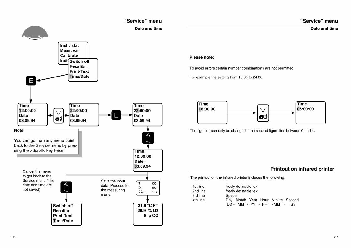
Cancel the menuto get back to theService menu (Thedate and time arenot saved)
Save the inputdata. Proceed tothe measuringmenu.
Note:
You can go from any menu pointback to the Service menu by pres-sing the >Scroll< key twice.
Please note:
To avoid errors certain number combinations are not permitted.
For example the setting from 16.00 to 24.00
The figure 1 can only be changed if the second figure lies between 0 and 4.
The printout on the infrared printer includes the following:
1st line freely definable text2nd line freely definable text3rd line Space 4th line Day Month Year Hour Minute Second
DD - MM - YY - HH - MM - SS
Printout on infrared printer
Time16:00:00
Time06:00:00
t t
“Service” menuDate and time

MaintenanceCalibration of CO measuring cell with test gas- only possible if an H2 content exists in test gas -
39
testo Maintenance
Replacing CO measuring cell
38
The cell coefficients are subject to programming protection. In order to change these parameters, the fluegas probe thermocouple connector must be replaced bythe calibration plug, which is enclosed with the standarddelivery, for the duration of the calibration.
Should you not have a test gas with H2 components, youcan only perform calibration via CO recalibration ( COrecalibration, page 41).Select the submenu gas calibration (service menu calibration gas calibration CO gas calibration).
Change the numerical values in lines 1 1and 2 accordingto the test certificate of test gas 1, the same in lines 3and 4 for test gas 2. The down key changes the figure,Enter activates the next figure.
Press the mbar/hPa key to enter the CO/H2 calibrationmode.
Start the pump.
Wait until the ADC values have stabilised and press theEnter key to set the zero point of the measuring cell.
Rinse the measuring cells with fresh air.
C a l i b .A D C - V a l u eC O : 0 0 0 3 1H 2 : 0 0 0 3 7
C a l i b .A D C - V a l u eC O : 0 0 0 3 1H 2 : 0 0 0 3 7
mbarhPa
E
E
STARTSTOP
C O . 1 1 0 0 0H 2 . 1 0 0 0 0C O . 2 1 0 0 0H 2 . 2 0 0 0 0
In order to replace the measuring cell, loosen the screwor the spring lock at the back of the instrument andremove the cover.
Please observer the following:- When inserting the call avoid putting any pressure
(e.g. thumb pressure) on the sensor (especially onthe bottom).
- The opening for the gas input at the front of the sensor should not be touched or jolted.
- The connecting clamps must not be turned or moved,as this may interupt the electrical connections in theinstrument or reduce tightness.
- The sensor must be screwed in such a way thatmaximum tightness is ensured. The tension of thescrews should, therefore, not be too great.
- The sensors should never be glued as dissolvingglue vapours may cause cracks in the plastic housingand destroy the electrodes.
Please observer the following instructions when replacing the cell- Loosen the screws of the measuring cell and remove
the measuring cell. Take out the O ring.- Remove the conncting cable from the measuring cell
(plug-in connection).- Place the O ring in the centre- Connect the cables.- Insert the measuring cell.
Once the cell has been inserted, calibration must beeffected, e.g. with the cell coefficients enclosed with thecell ( calibration of CO measuring cell with cell coeffi-cients, page 42).
Li screws (3x)0100.2012
CO meas. cell
O ring0135.2027
(Measuring chamber)

MaintenanceCO recalibration
- for test gases without H2 -
41
testo Calibration of CO measuring cell with test gas- only possible if an H2 content exists in test gas -
Calibration
40
The cell coefficients are subject to programming protection. In order to change these parameters, the fluegas probe thermocouple connector must be replaced bythe calibration plug, which is enclosed with the standarddelivery, for the duration of the calibration.
Select the submenu recalibration of CO cell (service-menu recalibration CO cell).Effect a measurement of the test gas (same procedureas measurement on page 14). Should the measuredvalue lie outside the tolerance, enter the correspondingnominal CO value.
The Down keys enable the figures to be altered in anumerical order.
Press Enter to jump to the next figure.
You can store this value by pressing the measuring key,the measuring instrument calculates the correctingfactor. You will automatically find yourself in the measurement menu.
E
TO2
CO2
CONO1 - η
CO: 3 0 0 0
CO: 4 0 0 0
CO: 4 0 0 0
Should you unintentionally find yourself inthis mode, always leave the menu via the
turnover key.Please switch off the instrument and then
switch on again.
Admit test gas 1 to the measuring cells. Apply the gaswithout pressure (max. 30 mbar) - for duration of approx.3-4 minutes.
Once the ADC values have stabilised (after approx. 3-4minutes) press the turnover key in order to set the gradient for test gas 1.
Admit test gas to the measuring cells. Apply the gaswithout pressure (max. 30 mbar) - for duration of approx.3-4 minutes.
Once the ADC values have stabilised (after approx. 3-4minutes) press the light in order to set the gradient fortest gas 2.
The measuring instrument performs cell calibration withthe measuring key, stores the values and jumps automatically to the calibration phase.
C a l i b .A D C - V a l u eC O : 0 0 5 2 7H 2 : 0 0 1 6 1
C a l i b .A D C - V a l u eC O : 0 0 5 2 7H 2 : 0 0 1 6 1
TO2
CO2
CONO1 - η
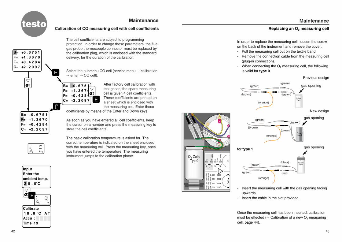
In order to replace the measuring cell, loosen the screwon the back of the instrument and remove the cover. - Pull the measuring cell out on the textile band- Remove the connection cable from the measuring cell
(plug-in connection).- When connecting the O2 measuring cell, the following
is valid for type 0
for type 1
- Insert the measuring cell with the gas opening facing upwards.
- Insert the cable in the slot provided.
Once the measuring cell has been inserted, calibrationmust be effected ( Calibration of a new O2 measuringcell, page 44).
Replacing an O2 measuring cell
43
testoCalibration of CO measuring cell with cell coefficients
Maintenance
42
Maintenance
O2-ZelleTyp 1
O2-ZelleTyp 0
gas opening
gas opening
(green)(green)
(brown)
(orange)
(orange)
(brown)
(brown)(black)
(green)
(orange)
(red)
The cell coefficients are subject to programming protection. In order to change these parameters, the fluegas probe thermocouple connector must be replaced bythe calibration plug, which is enclosed with the standarddelivery, for the duration of the calibration.
Select the submenu CO cell (service menu calibrationenter CO cell).
After factory cell calibration withtest gases, the spare measuringcell is given 4 cell coefficients.These coefficients are printed ona sheet which is enclosed withthe measuring cell. Enter these
coefficients by means of the Enter and Down keys.
As soon as you have entered all cell coefficients, keepthe cursor on a number and press the measuring key tostore the cell coefficients.
The basic calibration temperature is asked for. The correct temperature is indicated on the sheet enclosedwith the measuring cell. Press the measuring key, onceyou have entered the temperature. The measuringinstrument jumps to the calibration phase.
B= +0 . 6 7 5 1F= +1 . 3 6 7 0F= +0 . 4 2 8 4C= +2 . 2 0 9 7
B= +0 . 6 7 5 1F= +1 . 3 6 7 0F= +0 . 4 2 8 4C= +2 . 2 0 9 7
B= +0 . 6 7 5 1F= +1 . 3 6 7 0F= +0 . 4 2 8 4C= +2 . 2 0 9 7
E
TO2
CO2
CONO1 - η
TO2
CO2
CONO1 - η
Calibrate1 8 . 8 °C A TAccu :Time=19
E
InputEnter theambient temp.2 0 . 0°C
E
O2-ZelleTyp 0
C
A
RS
violettvioletviolet
gelbyellowjaune
graugreygris
RA
ST
yp 0
Typ
1
brbr
swbr
or
gngnrtgn or
O2
CO
/H2
weißwhiteblanc
C
(brown)(brown)
(green)(green)
gas opening
Previous design
New design
O2 celltype 0

testo Maintenance
Calibration of a new O2 measuring cell
44
The cell coefficients are subject to programming protection. In order to change these parameters, the fluegas probe thermocouple connector must be replaced bythe calibration plug, which is enclosed with the standarddelivery, for the duration of the calibration. We recommend the use of the mains unit to guarantee anadaquate power supply.
Select the submenu gas calibration of a O2 measuring cell (service menu calibration gas calibration O2 calibration).
The display questions the type of O2 sensor used (see label on the measuring cell). You can confirm that the setting is correct by pressing the Enter key.
(Should the O2 sensor type displayed be incorrect,press the turnover key and then use the burner keyto correct the sensor type displayed. Confirm with the measuring key).
Start O2 cell calibration with the Enter key.You can stop or interrupt this mode via the turnoverkey.
Calibration and storage of the ADC values is effectedautomatically. The measuring cell (type 0) requires approx. 70 minutes, type 1 requires roughly 25 minutes.
Remove the calibration plug when the instrument asks. The instrument jumps to a calibration phase and is then operational.
Calibration of a new O2 measuring cell
Maintenance
45
Use the arrow key to jump directly to the menu whichenables the entry to be changed. Save the alterationwith the measuring key. You will then autmatically findyourself in the O2 cell calibration phase.
TO2
CO2
CONO1 - η
O 2 - S e n s o r -t y p e = 1 ?N o < B >Y e s < E >
a u t o m a t .O 2 - C a l i b r .S t o p < D >S t a r t < E >
a u t o m a t .O 2 - C a l i b r . O 2 : 0 5 0 9 2T i m e = 1 3 2 7
E
E
E
C O G a s c a lN O G a s c a lO 2 C a l i b r .
O 2 - S e n s o r -t y p e = 1
O 2 - S e n s o r -t y p e = 0
Note:The calibration of the O2 cell in
rooms with a low O2 contents (nofresh air)leads to error messa-
ges or incorrect measurements
Note:Keeping the measuring instruments in rooms where
solvents are stored leads to the damage of themeasuring cells.

Maintenance
Determining the instrument version
47
testo Maintenance
Replacing a NO measuring cell
46
Press the turnover key during the calibration phase. Theinstrument type appears which gives information on thefitted cells.
342-1: O2/CO343-2: O2/NO342-3: O2/CO/NO
- t e s t o -- 3 4 2 - 3 -G B V . 2
The testo 342 NO measuring cell cannot be replaced bythe user himself, as it is situated inside the instrumentand a time-consuming calibration is necessary due tothe high accuracy requirements. The instrument shouldbe returned to the factory or to an authorised dealer forthe replacement of the NO measuring cell.
The corresponding menu NO cell in gas calibrationmenu (service menu) is only for authorised servicedepartments.

Error messages
49
testo Error messages
48
Cause: The calibration plug was not connected for calibration.
Result: The programming protection for the parameters could not be reserved.
Remedy: Insert the calibration plug (left connection socket = temperature input for the flue gas probe).
Cause: The calibration plug was not removed after calibration.
Result: The programming protection for the parameters could not be activated.
Remedy: Remove the calibration plug (left connection socket = temperature input for the flue gas probe).
U s e t h e s e r v i c ep l u g
R e m o v e t h e s e r v i c ep l u g
Cause: There is NO in the instrument.Result: The calibration time of the measuring cell is
considerably longer (when the instrument is next switched back on), if long -term measurements are effected in this high concentration.This has no effect on the measuring cell.
Remedy: Only continue measurements when urgent and rinse the measuring cells with fresh air.
N a t u r . g a s2 1 7 . 8 ° C F T
8 . 2 % O 2N O ?
C a l i b r a t e1 8. 8 ° C A TA c c u :T i m e : 5 8 N O ?
Cause: Instrument has delected too high a level of H2
in the CO cell.Result: The calibration time is longer.Remedy: If the instrument does not leave the calibration
phase the CO cell must be changed.
N a t u r . g a s2 1 7 . 8 ° C F T
8 . 2 % O 2H 2 ?
C a l i b r a t e1 8. 8 ° C A TA c c u :T i m e : 5 8 H 2 ?
Cause: The instrument temperature is below +4 °C.Result: The instrument is not operational and remains
in the calibration phase.Remedy: Increase ambient temperature.
N a t u r . g a s2 1 7 . 8 ° C F T
8 . 2 % O 2D T ?
C a l i b r a t e1 8. 8 ° C A TA c c u :T i m e : 5 8 G T ?
Cause: Insufficient power supply of the instrument.Result: If the battery voltage drops below 5.5V,
automatic disconnection follows.Remedy: Connect the mains unit and recharge the
battery.
N a t u r . g a s2 1 7 . 8 ° C A T
8 . 2 % O 2V d ?
C a l i b r a t e1 8. 8 ° C A TA c c u :T i m e : 5 8 V d ?
Cause: There is CO in the instrument.Result: The calibration time of the measuring cell is
considerably longer (when the instrument is next switched back on), if long-term measurements are effected in this high concentration. This has no effect on the measuring cell.
Remedy: Only continue measurements when urgent and rinse the measuring cells with fresh air.
N a t u r . g a s21 7 . 8 ° C F T
8 . 2 % O2CO?
C a l i b r a t e1 8. 8 ° C A TA c c u :T i m e : 5 8 C O ?
Cause: 1. Thermocouple connection of the flue gas probe is not connected.2. The temperature part of your flue gas probeis faulty.
Result: Measurement continues, but FT will not be measured.
Remedy: Check the thermocouple cennection or insert new thermocouple.
N a t u r . g a s- - - - - - C F T
8 . 2 % O 2T c ?
C a l i b r a t e- - - - - - C A TA c c u :T i m e : 5 8 T c ?

Calculation information
Information on the calculation of CO2-value,flue gas loss and excess air value
The following equations are used for calculating the listedvalues:
CO2-value:
CO2max : fuel specificmax. CO2-value
O2set : set O2-valueO2 : measured oxygen content
Excess air λ:
Resolution 0.1 %
Interruption of calculation at 19 % O2
Gross EffenciencyEffG:
Net EffenciencyEffN:
Kgr : fuel specific valueFT : flue gas temperatureAT : ambient temperatureK1 : fuel specific valueCO : measured CO value in %CO2 : measured CO2 value in %Qgr : fuel specific valueQnet : fuel specific valueX : fuel specific value
(MH2O + 9 * H)
- for fuel specific values see page 22 -51
testo Error messages
50
Cause: 1. The voltage of the internal rech. battery hasdropped below the 3.5 limit.2. Malfunction of the NO measuring switch.
Result: The NO measuring cell is inactive.Remedy: 1. Press Enter and recharge the battery (for at
least 2 hours). Should the display not change to calibration phase in the 10 secondsafter the Enter key has been pressed, an errorhas occured which must/can be repaired by an authorised service department.
S e l f - t e s tf a u l t .S e r v i c e i sr e q u i r e d
N O - C e l li s n o ts w i t c h e do n
P l e a s e u s et h e < E >k e y t os w i t c hM e a s u r e m .
N O i s n o tp o s s i b l ef o r 2 h r s .
Cause: Instrument errorResult: Measuring instrument is not operational.Remedy: Return instrument for repair.
1 0 . 4 % C O 21 1 % q A1 . 5 0 λ
R i n s i n g
Cause: The NO or CO concentrations exceed the upper limit during the measurement (disconnection according to setting in instrument).
Result: Measuring instrument not operational.Remedy: Remove flue gas probe from flue gas and
rinse in fresh air.
Cause: O2 cell is used up.Result: The measurement will continue, the accuracy
indicated in the data sheet can no longer be observed.
Remedy: Replace the O2 cell.
O2 c e l : ! ? !2 1 7 . 8 ° C F T
4 3 p u C OC a l i b r a t e1 8 . 8 ° C A TA c c u :T i m e = 1 9 0 2 ?
CO2 = CO2max xO2set. - O2
O2set.
λ = x 100−1O2set. - O2
O2set.
100 - - -CO2
Kgr * (FT - AT)
CO2 + CO
K1 * CO
Qgr x 1000
X * (2488 + 2.1 * FT - 4.2 * AT)
100 - - -CO2
Knet * (FT - AT)
Qnet * (CO2 + CO)
K1 * Qgr * CO
Qnet x 1000
X * (210 + 2.1 * FT - 4.2 * AT)
Technical data/Warranty
Temperature measurement:NiCr-Ni(Al):Meas. range: -40 to +1200 °C
(-40 to +2190 °F)Max. tolerance: ±0.5 °C/°F (0 to 100 °C)
(+32 to +210 °F)±0.5 % of m.v. (from +100°C/+210 °F)
Resolution: 0.1 °C / 1 °C (from +1000 °C/+1830 °F)Sensor: Thermocouple type K
(NiCr-NiAl according to DIN IEC 584, part 2, class 1)
NTC:Meas. range: -10 to +100 °C (+15 to +210 °F)Max. tolerance: ±0.5 °C/°F Resolution: 0.1 °C/°F
Draught:Meas. range: ±50 mbarResolution: 0.01 mbarMax. tolerance: ±0.03 hPa absolute (up to 3.00 mbar)
±2 % of m.v. (up to 50 mbar)
O2 measurement:Meas. range: 0 to 21 vol.%Max. tolerance: ±0.2 vol.% absolute Resolution: 0.1 vol.%Meas. procedure: electrochemical meas. cellsResponse time t90: approx. 40 sec.
CO2 measurement:Meas. range: 0 to CO2max
Max. tolerance: ±0.2 vol.% Resolution: 0.1 vol.%Meas. procedure: digital calculation from O2
Response time t90: approx. 60 sec.
53
testo Calculation information
Information on the calculation of CO2-value,flue gas loss and excess air value
52
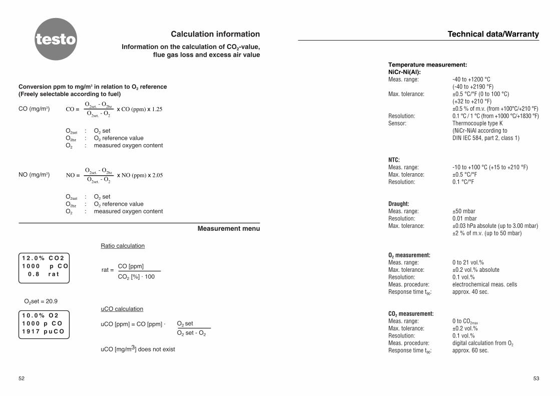
Conversion ppm to mg/m3 in relation to O2 reference(Freely selectable according to fuel)
CO (mg/m3)
O2set : O2 setO2bz : O2 reference valueO2 : measured oxygen content
NO (mg/m3)
O2set : O2 setO2bz : O2 reference valueO2 : measured oxygen content
CO = x CO (ppm) x 1.25O2set. - O2
O2set. - O2bz
CO = x CO (ppm) x 1.25O2set. - O2
O2set. - O2bz
NO = x NO (ppm) x 2.05O2set. - O2
O2set. - O2bz
Measurement menu
1 2 . 0 % C O 21 0 0 0 p C O
0 . 8 r a t
1 0 . 0 % O 21 0 0 0 p C O1 9 1 7 p u C O
Ratio calculation
uCO calculation
uCO [ppm] = CO [ppm] ·
uCO [mg/m3] does not exist
O2set = 20.9
CO [ppm]
CO2 [%] · 100rat =
O2 set
O2 set - O2
Ordering data
55
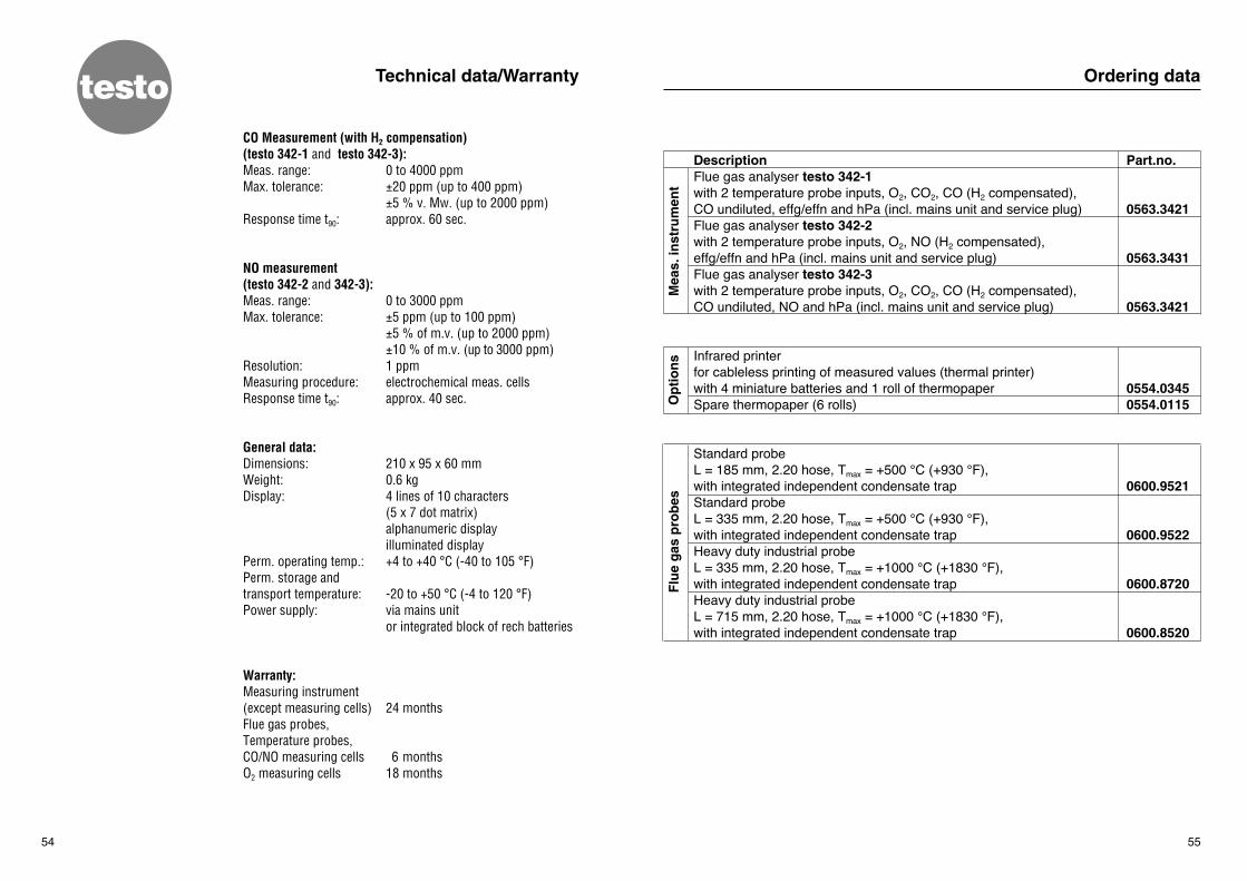
testoCO Measurement (with H2 compensation)(testo 342-1 and testo 342-3):Meas. range: 0 to 4000 ppmMax. tolerance: ±20 ppm (up to 400 ppm)
±5 % v. Mw. (up to 2000 ppm)Response time t90: approx. 60 sec.
NO measurement(testo 342-2 and 342-3):Meas. range: 0 to 3000 ppmMax. tolerance: ±5 ppm (up to 100 ppm)
±5 % of m.v. (up to 2000 ppm)±10 % of m.v. (up to 3000 ppm)
Resolution: 1 ppmMeasuring procedure: electrochemical meas. cellsResponse time t90: approx. 40 sec.
General data:Dimensions: 210 x 95 x 60 mmWeight: 0.6 kgDisplay: 4 lines of 10 characters
(5 x 7 dot matrix)alphanumeric displayilluminated display
Perm. operating temp.: +4 to +40 °C (-40 to 105 °F)Perm. storage and transport temperature: -20 to +50 °C (-4 to 120 °F)Power supply: via mains unit
or integrated block of rech batteries
Warranty:Measuring instrument(except measuring cells) 24 monthsFlue gas probes,Temperature probes,CO/NO measuring cells 6 monthsO2 measuring cells 18 months
Technical data/Warranty
54
Description Part.no.Flue gas analyser testo 342-1with 2 temperature probe inputs, O2, CO2, CO (H2 compensated),CO undiluted, effg/effn and hPa (incl. mains unit and service plug) 0563.3421Flue gas analyser testo 342-2with 2 temperature probe inputs, O2, NO (H2 compensated),effg/effn and hPa (incl. mains unit and service plug) 0563.3431Flue gas analyser testo 342-3with 2 temperature probe inputs, O2, CO2, CO (H2 compensated),CO undiluted, NO and hPa (incl. mains unit and service plug) 0563.3421
Infrared printerfor cableless printing of measured values (thermal printer)with 4 miniature batteries and 1 roll of thermopaper 0554.0345Spare thermopaper (6 rolls) 0554.0115
Standard probeL = 185 mm, 2.20 hose, Tmax = +500 °C (+930 °F),with integrated independent condensate trap 0600.9521Standard probeL = 335 mm, 2.20 hose, Tmax = +500 °C (+930 °F),with integrated independent condensate trap 0600.9522Heavy duty industrial probeL = 335 mm, 2.20 hose, Tmax = +1000 °C (+1830 °F),with integrated independent condensate trap 0600.8720Heavy duty industrial probeL = 715 mm, 2.20 hose, Tmax = +1000 °C (+1830 °F),with integrated independent condensate trap 0600.8520
Op
tio
ns
Mea
s. in
stru
men
tF
lue
gas
pro
bes

Option: Infrared printer
General features
57
testo Ordering data
56
For your protection, the printer has been tested to different national and international safety standards. The tests include electronical/mechanical safety, radiointerference, ergonomics, acoustics and hazardousmaterials. Where required, approvals obtained fromindependant test institutes are shown on the bottom ofthe product.
The printer was tested in a typical system configurationand corresponded with the FTZ 1046/84. The instrumentwas, thus, issued with the VDE radio trade mark, withthe 0871-B/P index for peripheral equipment.
Switching on the infra-red printerPush the switch to “I”. The control lamp lights up whenthe printer is in operation.
Description Part.no.Air probe (NTC)for separate measurement of ambient air temperature,Tmax. = +100 °C (+210 °F), L = 300 mm, with cone 0600.9791Magnetic holding for air probe 0600.9791 0554.0431Air probe (NTC)Shaft end probe for separate measurement of ambient temp.Tmax. = +80 °C (+175 °F), L = total of 60 mm 0600.3691Temperature probe (NiCr-NiAl) for surface measurement,very quick, meas. range -200 to +500 °C (-60 to +265 °F) 0600.4593Temperature pipe wrap probe (NiCr-NiAl for pipes with diameter of5 to 63 mm, meas. range -50 to +130 °C (-60 to +265 °F) 0600.4593
Holding fixture for flue gas probe 0554.0094Carrying case for testo 342 with magnetic disk and carrying strap 0516.0014System case for testo 342flue gas probe and printer 0516.0134Service case (leather) for testo 342flue gas probe, printer andother tool 0516.0100
Spare set of O2 meas. cell 0390.9000Spare meas. cell CO (H2 compensated) 0390.0019Spare filter material for flue gas probe filter unit 0554.0084Spare thermocouple for flue gas probe (l. 335 mm) 0430.0050Spare thermocouple for flue gas probe (l. 185 mm) 0430.0055
Tem
per
atu
reA
cces
sori
esS
par
e p
arts

Option: Infrared printer
Batteries
59
testo Option: Infrared printer
Batteries
58
Insert new batteries, if the following occurs:
- The print contrast is too weak, even at the highestsetting.
- Printing takes longer as printing head moves at amuch slower speed.
- If a large amount of information - over 200 characters - is transmitted by the meas. instrument,printing slows because the printer pauses momentarily before printing each new line. However,the printing head moves across the paper at normalspeed. This is not a sign of low batteries.
- Printing stops before all the information has beenprinted on one line.
- The battery capacity (printed at the end of the sefltest) lies between 0.1 (weak) and 4.5 (high).
If you are not intending to use the printer in the nearfuture, you should remove the batteries before storingthe printer.
You can also use rechargeable batteries; they must,however, be charged outside the printer with a commercial charger (see ordering data on p. 53). Thebattery life of the rech. batteries between each charge isless than that of alcaline batteries.
Use 4 x 1.5 V alcaline AA batteries.
Remove the battery compartment cover.
Insert the new batteries as shown.
Replace the battery compartmentcover.
After approx. 10 minutes of inactivity, the printer willswitch to a low-power mode in order to conserve the batteries. Press the paper feed key to reactivate the printer.
In order to prolong the battery life, set the contrast to thelowest acceptable setting and switch the printer off afteruse.

Option: Infrared printer
Self-test
If you think that the printer is not operating properly, youcan run a self-test.
Switch the instrument off. Hold the arrow key down whileturning the printer on.
If the printer files the self-test, rerun the test to verify theresults, before sending it back for repair.
Incorrect or missing information
If the symbol is printed, it means that the printer hasdetected faulty data due to interference in the incominginfrared signals.
This is usually caused by unsuitable positioning of theprinter and measuring instrument (i.e. distance betweenthe objects and angle of transmission), interference inthe transmission link (infrared signal), flashes of light orinterference from other infrared-controlled instruments.
The symbol is printed when information is lost, asthe printer cannot print quickly enough to keep up withthe incoming data. This is usual when the batteries arelow. This can be rectified by inserting new batteries or ablock of rechargeable batteries.
61
testo Option: Infrared printer
Changing the paper
60
Never use the printer without paper. For best results, use black-printing thermopaper.
Always use the arrow key (paper feed) to move thepaper. Do not pull the paper backwards through the printer.
Replace the paper before it runs out completely.
Open the door to the paper compartment.
If the paper is stuck to the empty paper roll, loosen thepaper with scissors and remove the remaining paperwith the arrow key.
Insert a new roll of paper. Do not use paper with folds oruneven edges. Avoid obstructions within the printingmechanism.
Position the paper as shown.
Hold the arrow key down (until the paper appears), whileyou insert the paper into the slot. If the paper jams, pull itback very slowly.
Insert the roll of paper and close the door to the papercompartment.

Option: Charger
The charger is suitable for charging 4 cylindrical cells aswell as a 9 V E block.
Starting the chargeConnect the charger to a 220/50 Hz socket. The chargeris activated when one or several rech. batteries are inserted. The red LED lights up. Observer polarity wheninserting the rech. batteries!
Recharging timeThe integrated control of the charging time is activatedwhen the charger begins recharging the batteries. Aftera charging time of 7 hours, the charger automaticallyswitches to compensating charge. This then guaranteesthat the rech. batteries will not be overloaded (providedthat the rech. batteries were empty when inserted) andthat they will remain ready for operation in the charger.The green LED lights up during the compensating charge phase.
Important notesPlease note that if the Charge is interrupted by disconnection from the mains unit or by the removal ofthe rech. batteries, the control of the loading time isdeactivated. When the charge is restarted, the chargerwill effect a complete reload. Therefore, the chargershould always remain connected to the mains unit whencharging and no other rech. batteries should be added,as these will only be charged for the remaining durationof the initial (i.e. the rech. batteries which are added laterwill not be fully charged).
Ending the chargeWe recommend that you leave the rech. batteries in thecharger until you need them. The charge is interruptedby disconnection from the mains unit or by the removalof the rech. batteries. The red or green LED switches off.
63
testo Option: Infrared printer
Transferring measured data
62
In order to transfer the measuring protocol from the measuring instrument to the infrared printer, point thetop of measuring instrument (IR transmitting diode)towards the infrared printer (i.e. the window on the right-hand side of the instrument). The distance between thehand instrument and the printer should not be more than2.0 m.
The transmission link between the two instruments mustbe straight and may not be broken by any objects.
When transferring data, both instruments must be heldsteady. It is possible to lay the instrument and printer onthe same (horizontal) level, e.g. on an opened systemcase.
60°
20°
10°

testo Option: Charger
As the charger cannot recognise the capacity of the inserted rech. batteries, only empty batteries should beinserted, in order to avoid overloading. We, therefore,recommend that you buy a second set of rech. batteriesso that one set is always in the charger and one in theinstrument.
64
mdr
0971.0680/01.96
mdr