Numerical simulation of blood flow in LAD models with different
25
Numerical simulation of blood flow in LAD models with different degrees and location of stenosis. 5 th ANSA & μET A International Conference Konstantinos Papadopoulos, Mitroglou Nicholas and Gavaises Manolis School of Engineering and Mathematical Sciences
Transcript of Numerical simulation of blood flow in LAD models with different
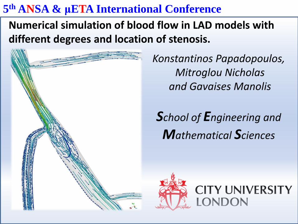
Numerical simulation of blood flow in LAD models with different degrees and location of stenosis.
5th ANSA & μETA International Conference
Konstantinos Papadopoulos, Mitroglou Nicholas
and Gavaises Manolis
School of Engineering and
Mathematical Sciences
OU
Numerical simulation of blood flow in LAD models with different degrees and location of stenosis. K. Papadopoulos, Mitroglou N. and Gavaises M.
5th ANSA & μETA International Conference`
Introduction/ Motivation
Morphing Boundary Conditions
Geometry/ Grid
Results and discussion
Solution: Description of the problem Case setup Results
Pre and Post processing: ANSA & Python scripts for geometry modification μETA and BETA scripts for result processing
1. Outline
5th ANSA & μETA International Conference`
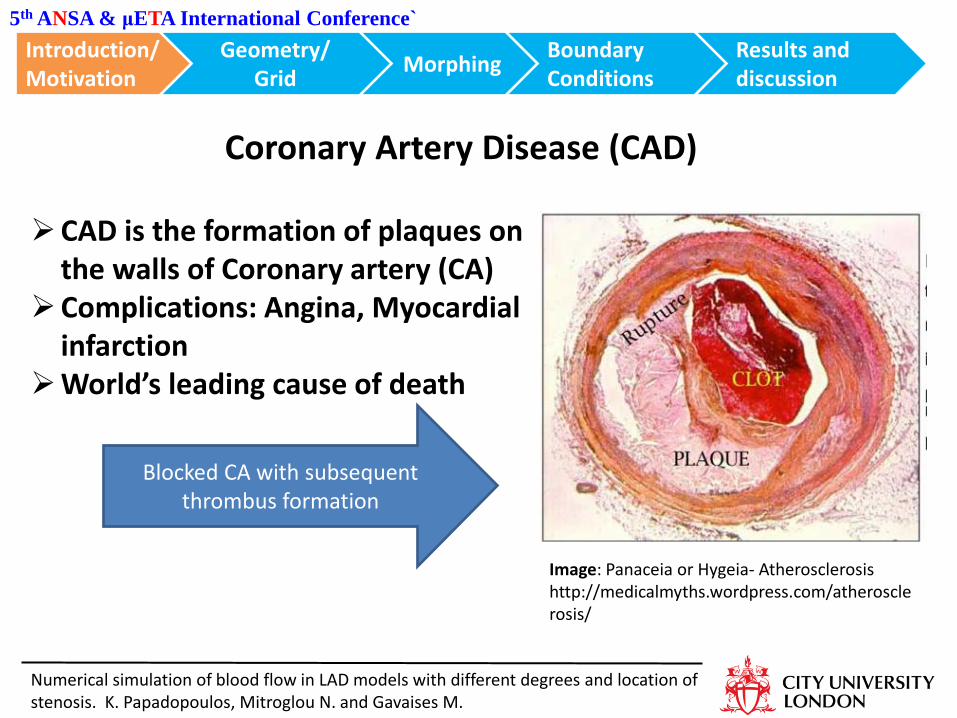
Coronary Artery Disease (CAD)
Image: Panaceia or Hygeia- Atherosclerosis http://medicalmyths.wordpress.com/atherosclerosis/
CAD is the formation of plaques on the walls of Coronary artery (CA)
Complications: Angina, Myocardial infarction
World’s leading cause of death
Blocked CA with subsequent thrombus formation
Introduction/ Motivation
Morphing Boundary Conditions
Geometry/ Grid
Results and discussion
Numerical simulation of blood flow in LAD models with different degrees and location of stenosis. K. Papadopoulos, Mitroglou N. and Gavaises M.
5th ANSA & μETA International Conference`
Image: Encyclopedia Britannica
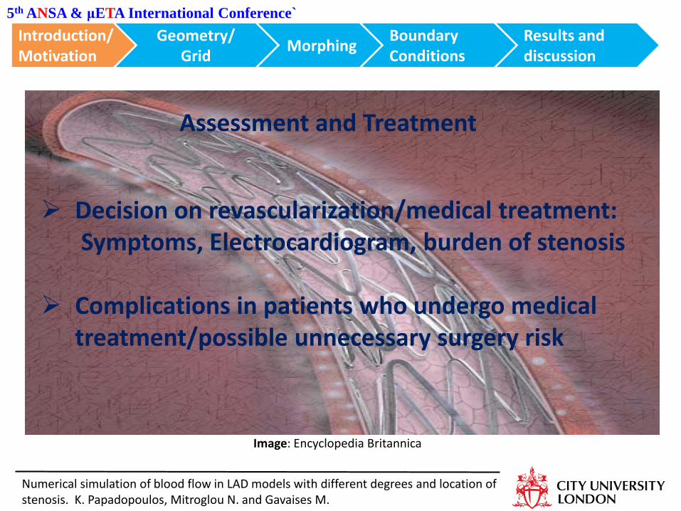
Assessment and Treatment
Decision on revascularization/medical treatment: Symptoms, Electrocardiogram, burden of stenosis
Complications in patients who undergo medical treatment/possible unnecessary surgery risk
Introduction/ Motivation
Morphing Boundary Conditions
Geometry/ Grid
Results and discussion
Numerical simulation of blood flow in LAD models with different degrees and location of stenosis. K. Papadopoulos, Mitroglou N. and Gavaises M.
Numerical simulation of blood flow in LAD models with different degrees and location of stenosis. K. Papadopoulos, Mitroglou N. and Gavaises M.
5th ANSA & μETA International Conference`
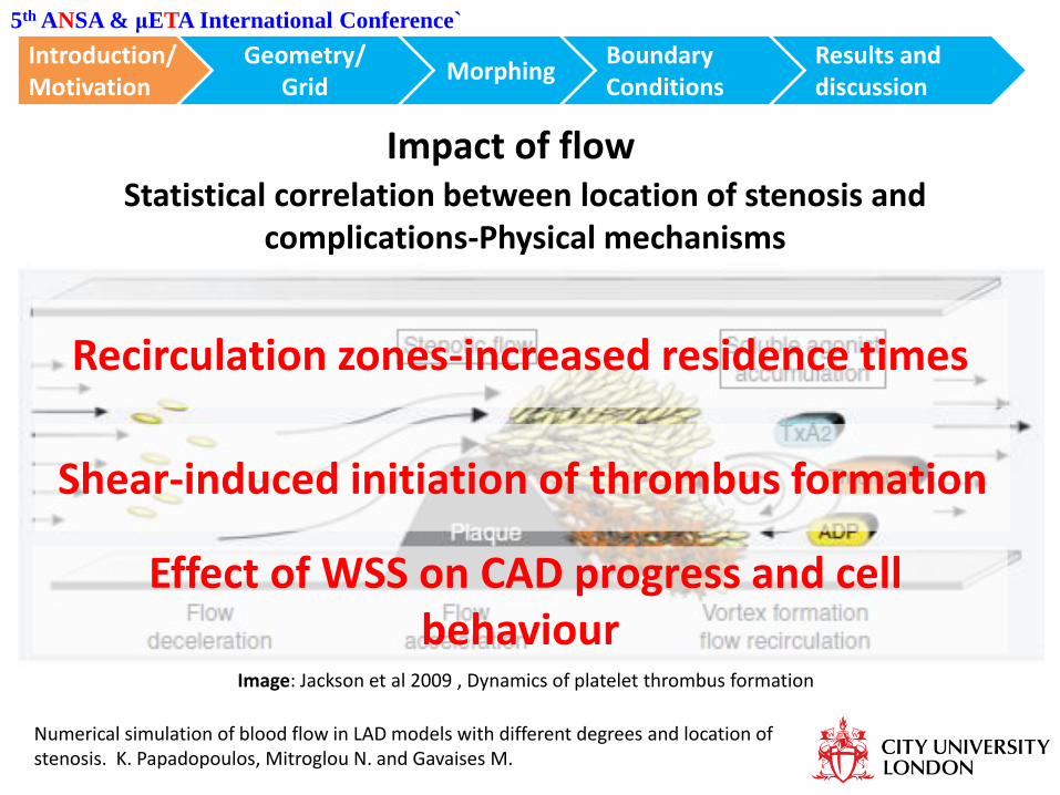
Impact of flow
Image: Jackson et al 2009 , Dynamics of platelet thrombus formation
Statistical correlation between location of stenosis and complications-Physical mechanisms
Recirculation zones-increased residence times
Shear-induced initiation of thrombus formation
Effect of WSS on CAD progress and cell behaviour
Introduction/ Motivation
Morphing Boundary Conditions
Geometry/ Grid
Results and discussion
5th ANSA & μETA International Conference`
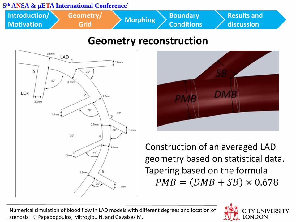
Geometry reconstruction
Construction of an averaged LAD geometry based on statistical data. Tapering based on the formula
𝑃𝑀𝐵 = 𝐷𝑀𝐵 + 𝑆𝐵 × 0.678
Introduction/ Motivation
Morphing Boundary Conditions
Geometry/ Grid
Results and discussion
Numerical simulation of blood flow in LAD models with different degrees and location of stenosis. K. Papadopoulos, Mitroglou N. and Gavaises M.
5th ANSA & μETA International Conference`
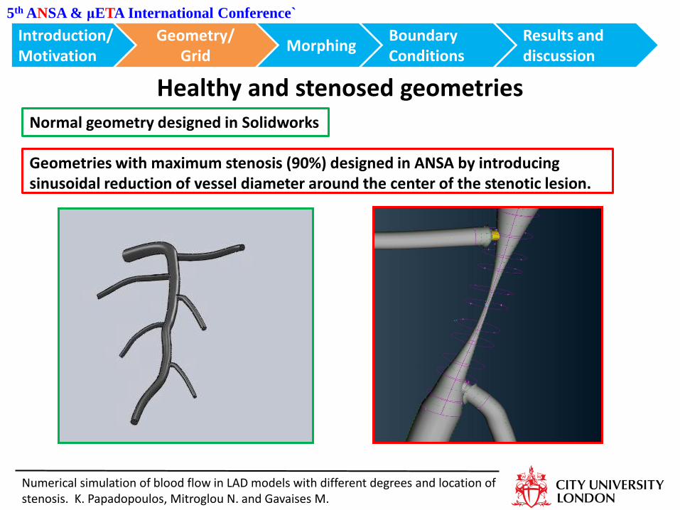
Healthy and stenosed geometries
Geometries with maximum stenosis (90%) designed in ANSA by introducing sinusoidal reduction of vessel diameter around the center of the stenotic lesion.
Normal geometry designed in Solidworks
Introduction/ Motivation
Morphing Boundary Conditions
Geometry/ Grid
Results and discussion
Numerical simulation of blood flow in LAD models with different degrees and location of stenosis. K. Papadopoulos, Mitroglou N. and Gavaises M.
Introduction/ Motivation
Morphing Boundary Conditions
Geometry/ Grid
Results and conclusions
5th ANSA & μETA International Conference`
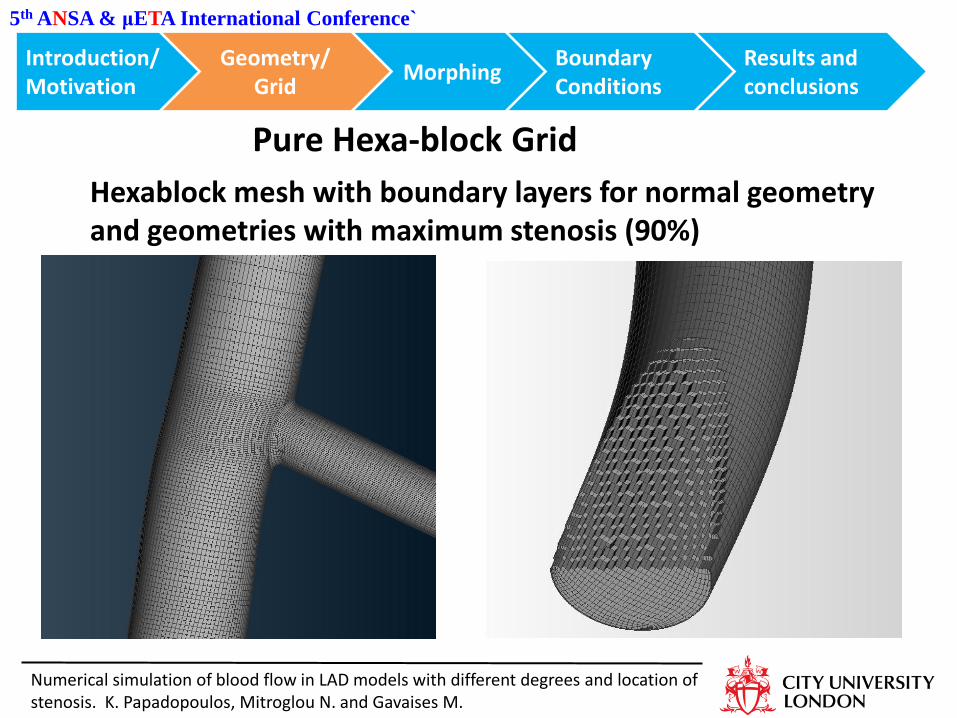
Pure Hexa-block Grid
Hexablock mesh with boundary layers for normal geometry and geometries with maximum stenosis (90%)
Numerical simulation of blood flow in LAD models with different degrees and location of stenosis. K. Papadopoulos, Mitroglou N. and Gavaises M.
5th ANSA & μETA International Conference`
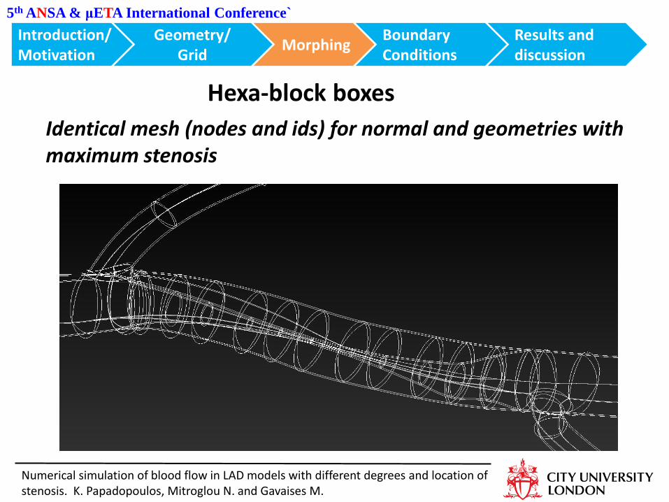
Hexa-block boxes
Identical mesh (nodes and ids) for normal and geometries with maximum stenosis
Introduction/ Motivation
Morphing Boundary Conditions
Geometry/ Grid
Results and discussion
Numerical simulation of blood flow in LAD models with different degrees and location of stenosis. K. Papadopoulos, Mitroglou N. and Gavaises M.
5th ANSA & μETA International Conference`
Numerical simulation of blood flow in LAD models with different degrees and location of stenosis. K. Papadopoulos, Mitroglou N. and Gavaises M.
Introduction/ Motivation
Morphing Boundary Conditions
Geometry/ Grid
Results and discussion
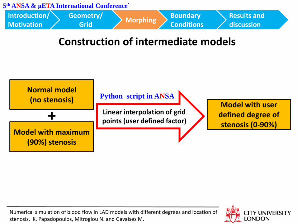
Construction of intermediate models
Normal model (no stenosis)
Model with maximum (90%) stenosis
+
Python script in ANSA Model with user
defined degree of stenosis (0-90%)
Linear interpolation of grid points (user defined factor)
5th ANSA & μETA International Conference`
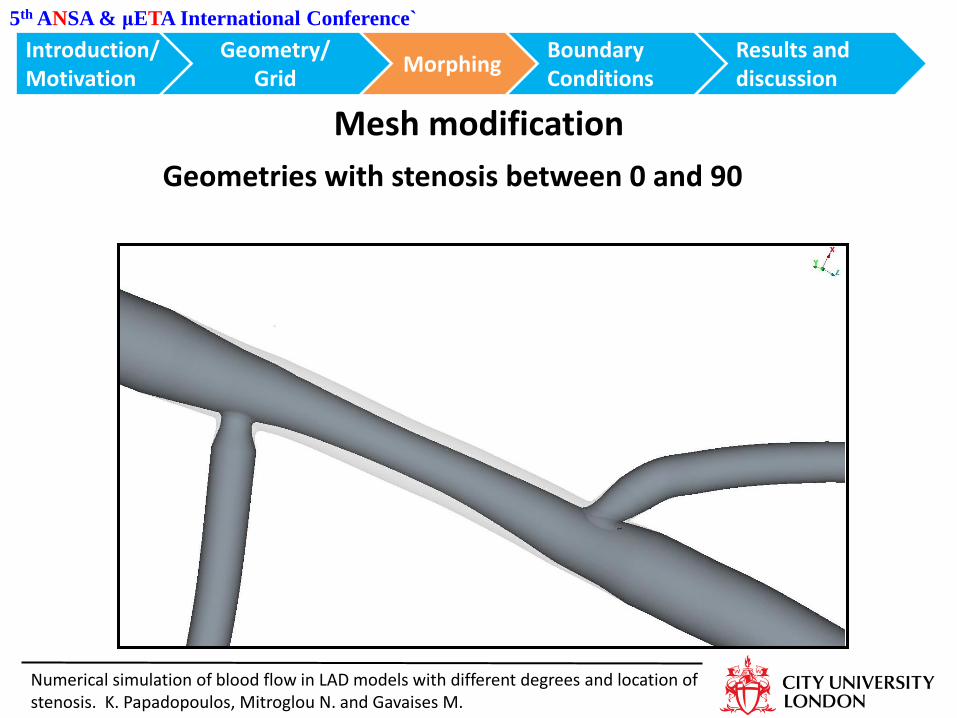
Mesh modification
Geometries with stenosis between 0 and 90
Introduction/ Motivation
Morphing Boundary Conditions
Geometry/ Grid
Results and discussion
Numerical simulation of blood flow in LAD models with different degrees and location of stenosis. K. Papadopoulos, Mitroglou N. and Gavaises M.
5th ANSA & μETA International Conference`
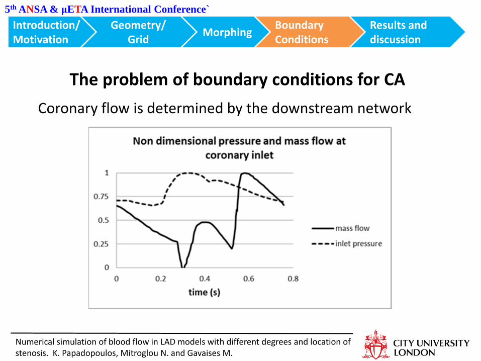
Coronary flow is determined by the downstream network
The problem of boundary conditions for CA
Introduction/ Motivation
Morphing Boundary Conditions
Geometry/ Grid
Results and discussion
Numerical simulation of blood flow in LAD models with different degrees and location of stenosis. K. Papadopoulos, Mitroglou N. and Gavaises M.
5th ANSA & μETA International Conference`
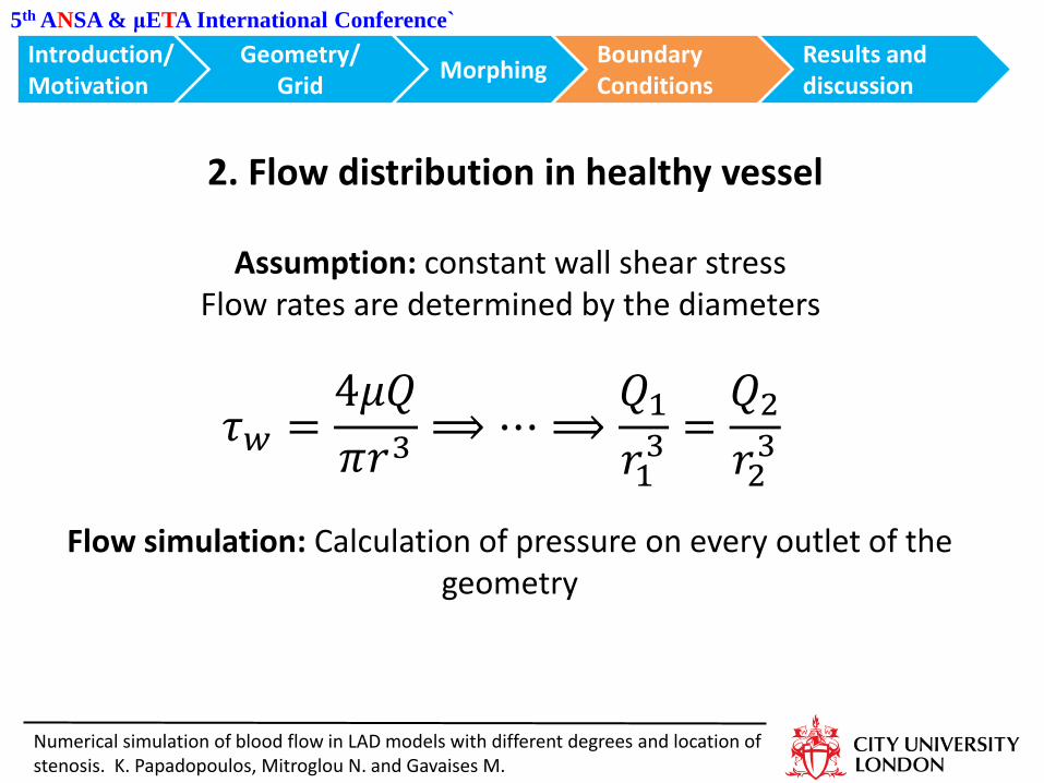
𝜏𝑤 =4𝜇𝑄
𝜋𝑟3⟹ ⋯ ⟹
𝑄1
𝑟13 =
𝑄2
𝑟23
2. Flow distribution in healthy vessel
Assumption: constant wall shear stress Flow rates are determined by the diameters
Flow simulation: Calculation of pressure on every outlet of the geometry
Introduction/ Motivation
Morphing Boundary Conditions
Geometry/ Grid
Results and discussion
Numerical simulation of blood flow in LAD models with different degrees and location of stenosis. K. Papadopoulos, Mitroglou N. and Gavaises M.
5th ANSA & μETA International Conference`
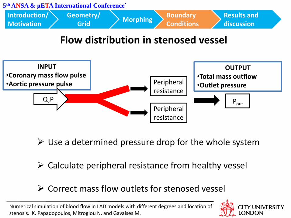
Peripheral resistance
Peripheral resistance
INPUT •Coronary mass flow pulse •Aortic pressure pulse
Q,P Pout
Flow distribution in stenosed vessel
OUTPUT •Total mass outflow •Outlet pressure
Use a determined pressure drop for the whole system
Calculate peripheral resistance from healthy vessel
Correct mass flow outlets for stenosed vessel
Introduction/ Motivation
Morphing Boundary Conditions
Geometry/ Grid
Results and discussion
Numerical simulation of blood flow in LAD models with different degrees and location of stenosis. K. Papadopoulos, Mitroglou N. and Gavaises M.
5th ANSA & μETA International Conference`
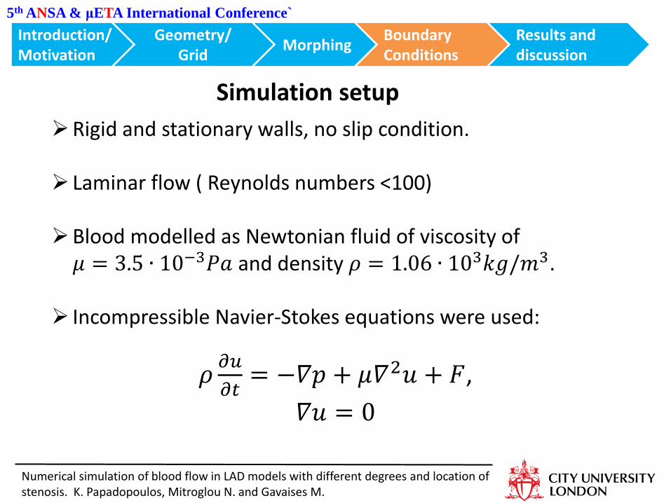
Simulation setup
Introduction/ Motivation
Morphing Boundary Conditions
Geometry/ Grid
Results and discussion
Rigid and stationary walls, no slip condition.
Laminar flow ( Reynolds numbers <100)
Blood modelled as Newtonian fluid of viscosity of 𝜇 = 3.5 ∙ 10−3𝑃𝑎 and density 𝜌 = 1.06 ∙ 103𝑘𝑔/𝑚3.
Incompressible Navier-Stokes equations were used:
𝜌𝜕𝑢
𝜕𝑡= −𝛻𝑝 + 𝜇𝛻2𝑢 + 𝐹,
𝛻𝑢 = 0
Numerical simulation of blood flow in LAD models with different degrees and location of stenosis. K. Papadopoulos, Mitroglou N. and Gavaises M.
5th ANSA & μETA International Conference`
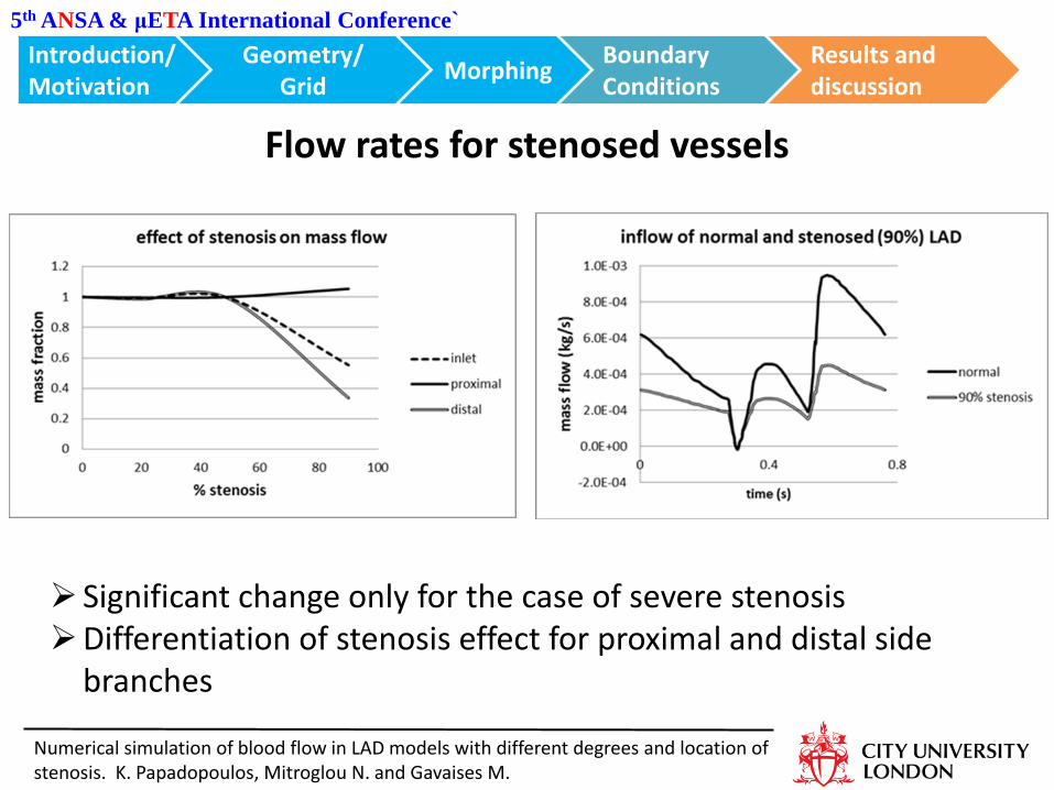
Flow rates for stenosed vessels
Significant change only for the case of severe stenosis Differentiation of stenosis effect for proximal and distal side
branches
Introduction/ Motivation
Morphing Boundary Conditions
Geometry/ Grid
Results and discussion
Numerical simulation of blood flow in LAD models with different degrees and location of stenosis. K. Papadopoulos, Mitroglou N. and Gavaises M.
Introduction/ Motivation
Morphing Boundary Conditions
Geometry/ Grid
Results and discussion
5th ANSA & μETA International Conference`
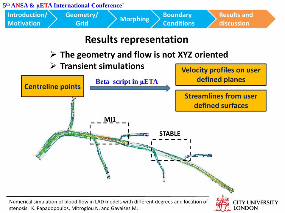
Results representation
The geometry and flow is not XYZ oriented Transient simulations
MI1
STABLE
Numerical simulation of blood flow in LAD models with different degrees and location of stenosis. K. Papadopoulos, Mitroglou N. and Gavaises M.
Centreline points Streamlines from user
defined surfaces
Velocity profiles on user defined planes Beta script in μETA
5th ANSA & μETA International Conference`
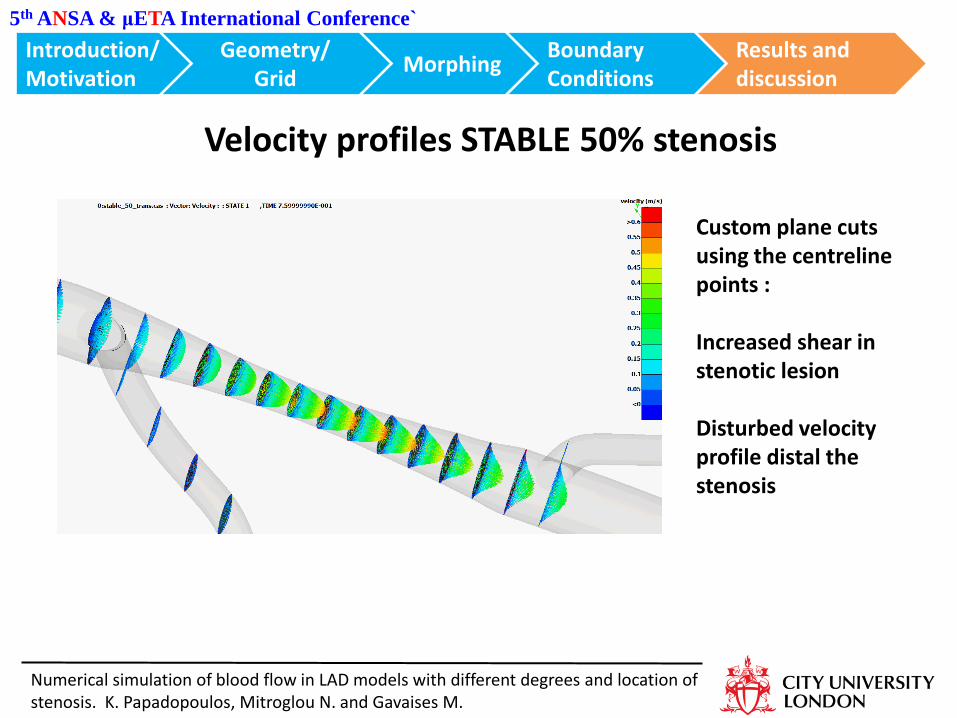
Velocity profiles STABLE 50% stenosis
Introduction/ Motivation
Morphing Boundary Conditions
Geometry/ Grid
Results and discussion
Numerical simulation of blood flow in LAD models with different degrees and location of stenosis. K. Papadopoulos, Mitroglou N. and Gavaises M.
Custom plane cuts using the centreline points : Increased shear in stenotic lesion Disturbed velocity profile distal the stenosis
5th ANSA & μETA International Conference`
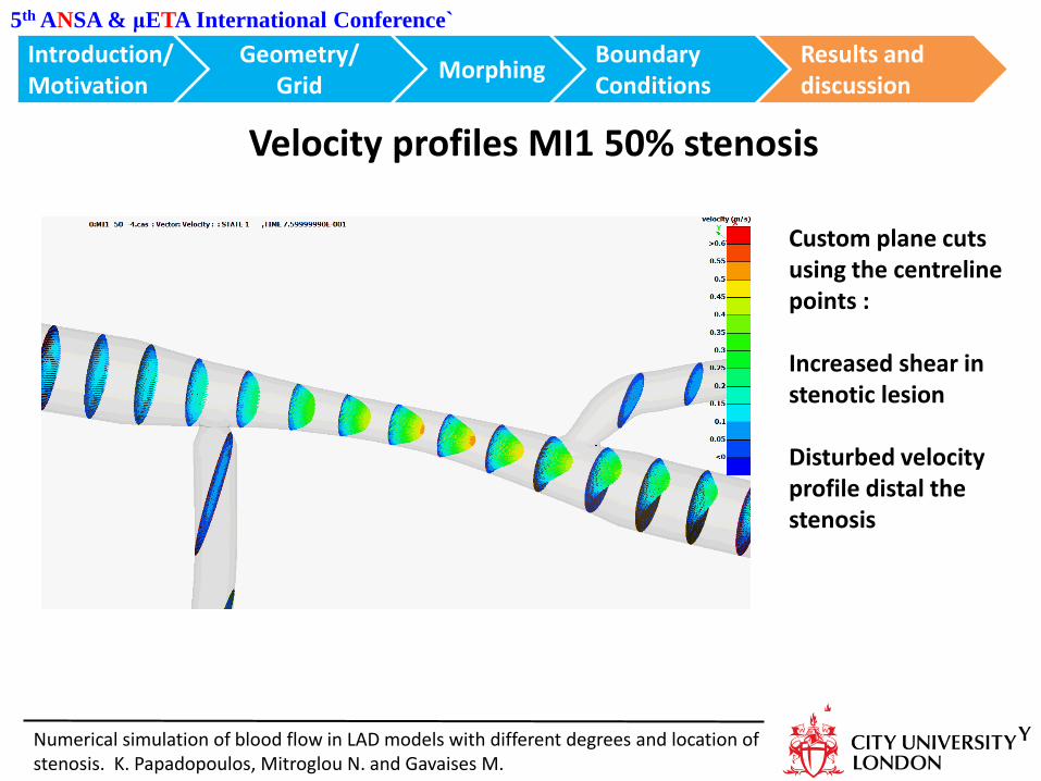
Velocity profiles MI1 50% stenosis
Introduction/ Motivation
Morphing Boundary Conditions
Geometry/ Grid
Results and discussion
Numerical simulation of blood flow in LAD models with different degrees and location of stenosis. K. Papadopoulos, Mitroglou N. and Gavaises M.
Custom plane cuts using the centreline points : Increased shear in stenotic lesion Disturbed velocity profile distal the stenosis
5th ANSA & μETA International Conference`
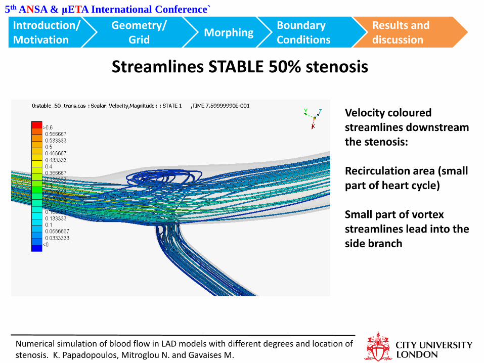
Streamlines STABLE 50% stenosis
Introduction/ Motivation
Morphing Boundary Conditions
Geometry/ Grid
Results and discussion
Numerical simulation of blood flow in LAD models with different degrees and location of stenosis. K. Papadopoulos, Mitroglou N. and Gavaises M.
Velocity coloured streamlines downstream the stenosis: Recirculation area (small part of heart cycle) Small part of vortex streamlines lead into the side branch
5th ANSA & μETA International Conference`
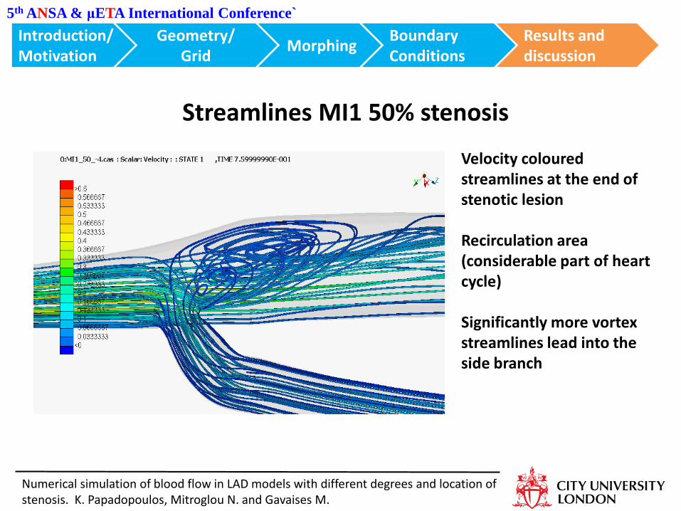
Streamlines MI1 50% stenosis
Introduction/ Motivation
Morphing Boundary Conditions
Geometry/ Grid
Results and discussion
Numerical simulation of blood flow in LAD models with different degrees and location of stenosis. K. Papadopoulos, Mitroglou N. and Gavaises M.
Velocity coloured streamlines at the end of stenotic lesion Recirculation area (considerable part of heart cycle) Significantly more vortex streamlines lead into the side branch
Introduction/ Motivation
Morphing Boundary Conditions
Geometry/ Grid
Results and conclusions
5th ANSA & μETA International Conference`
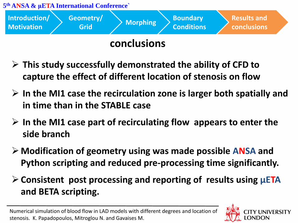
This study successfully demonstrated the ability of CFD to capture the effect of different location of stenosis on flow
In the MI1 case the recirculation zone is larger both spatially and in time than in the STABLE case
In the MI1 case part of recirculating flow appears to enter the side branch
Modification of geometry using was made possible ANSA and Python scripting and reduced pre-processing time significantly.
Consistent post processing and reporting of results using μΕΤΑ and BETA scripting.
Numerical simulation of blood flow in LAD models with different degrees and location of stenosis. K. Papadopoulos, Mitroglou N. and Gavaises M.
conclusions
5th ANSA & μETA International Conference`
Numerical simulation of blood flow in LAD models with different degrees and location of stenosis. K. Papadopoulos, Mitroglou N. and Gavaises M.
Introduction/ Motivation
Morphing Boundary Conditions
Geometry/ Grid
Results and discussion
Thank you
Special thanks to BETA support team
5th ANSA & μETA International Conference`
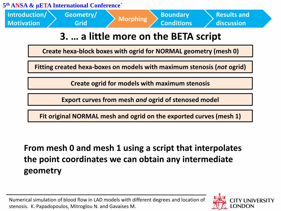
3. … a little more on the BETA script
Introduction/ Motivation
Morphing Boundary Conditions
Geometry/ Grid
Results and discussion
Numerical simulation of blood flow in LAD models with different degrees and location of stenosis. K. Papadopoulos, Mitroglou N. and Gavaises M.
Create hexa-block boxes with ogrid for NORMAL geometry (mesh 0)
Fitting created hexa-boxes on models with maximum stenosis (not ogrid)
Create ogrid for models with maximum stenosis
Export curves from mesh and ogrid of stenosed model
Fit original NORMAL mesh and ogrid on the exported curves (mesh 1)
From mesh 0 and mesh 1 using a script that interpolates the point coordinates we can obtain any intermediate geometry
Introduction/ Motivation
Morphing Boundary Conditions
Geometry/ Grid
Results and conclusions
5th ANSA & μETA International Conference`
Numerical simulation of blood flow in LAD models with different degrees and location of stenosis. K. Papadopoulos, Mitroglou N. and Gavaises M.