Numerical Analysis of Combustor Flow Fields in Supersonic...
7
Abstract—In this numerical study, supersonic combustion of hydrogen has been presented for Mach 2. The combustor has a single fuel injection parallel to the main flow from the base. Finite rate chemistry model with k-ε model and Spalart-Allmaras (S-A) Model have been used for modeling of supersonic combustion. The coupled phenomena of mixing and burning cm only be numerically modeled with the inclusion of a finite-rate chemical kinetic mechanism. The main issue in supersonic combustion is proper mixing within short burst of time. Attention is paid to the local intensity of heat release, which determines, together with the duct geometry, techniques for flame initiation and stabilization, injection techniques and quality of mixing the fuel with oxidizer, the gas-dynamic flow regime. The two-dimensional mathematical model involves the k-ε and Spalarts-Allmaras turbulence model, modified for supersonic compressibility, and a detailed kinetic mechanism of mixture combustion. The five main parameters were considered like Mach number stagnation temperature, mass fraction, stagnation pressure and velocity. The result shows the better mixing of fuel and the flame speed increases almost linearly. The stagnation temperature in the combustion reaches up to 2820K. Fluctuation in pressure and Mach number was due to shock train. Index Terms—flame speed, Mach number, supersonic combustion, Spalart-Allmaras, finite rate, stagnation temperature. I. INTRODUCTION Supersonic combustion is the key enabling technology for sustained hypersonic flights. In scramjet engines of current interest, the combustor length is typically of the order of 1 m, and the residence time of the mixture is of the order of Milliseconds. Due to the high supersonic flow speed in the combustion chamber, problems arise in the mixing of the reactants, flame anchoring and stability and completion of combustion within the limited combustor length. The flow field in the scramjet combustor is highly complex. It is shown that when the flight speed is low, the kinetic energy of the air is not enough to be used for the optimal compression. Further compression by machines is needed in order to obtain a higher efficiency. For example, a turbojet employs a turbine machine for further compression. When the flight speed is higher than a certain value, the air flow entering a combustor will remain to be supersonic after the optimal compression. With a further compression (i. e. deceleration), the efficiency Manuscript received February 25, 2011; revised May 10, 2011. K.M.Pandey, Member IACSIT, Department of Mechanical Engineering, N.I.T Silchar, Assam, India (email: [email protected]). A.P. Singh, Member IACSIT, Department of Mechanical Engineering, N.I.T Silchar, Assam, India(email : [email protected]). of the engine will decrease. Therefore the combustion has to take place under the supersonic flow condition. This kind of air-breathing engine, which works under hypersonic flight condition, is called the supersonic combustion ramjet (Scramjet). The term of "supersonic combustion" applied here means the combustion in a supersonic flow. The efficiency of heat supply to the combustion chamber based on the analysis of literature data on combustion processes in a confined high-velocity and high-temperature flow for known initial parameters is considered. This was given by Tretyakov[1]. The process efficiency is characterized by the combustion completeness and total pressure losses. The main attention is paid to the local intensity of heat release, which determines, together with the duct geometry, techniques for flame initiation and stabilization, injection techniques and quality of mixing the fuel with oxidizer, the gas-dynamic flow regime. The study of supersonic combustion of hydrogen has been conducted by Aso et al. [2] using a reflected-type shock tunnel which generated a stable supersonic air flow of Mach number of 2 with the total temperature of 2800K and the total pressure of 0.35 MPa. He concluded that The Schlieren images show that the increase of injection pressure generated strong bow shock, resulting in the pressure loses. Supersonic combustion data obtained at the low static temperatures appropriate for an efficient scramjet engine have been reviewed by Cain and Walton [3]. Attention is focused at the methods by which the fuel was ignited and combustion maintained. This is particularly common for supersonic combustion experiments and many examples are found in the literature of experiments conducted with inlet temperatures much higher than practical in flight. There is a good reason for this: it is difficult to sustain a hydrogen or hydrocarbon flame in a low temperature supersonic flow. A well designed combustor makes this possible; a less effective combustor can be made to function simply by elevating the static temperature until spontaneous ignition is achieved. Low combustor entry temperature is desirable/essential due to intake and nozzle limitations. This paper aims in particular at the application of scalar and joint scalar-velocity-turbulent frequency PDF (probability density functions) methods to supersonic combustion done by Gerlinger et al. [4]. Supersonic combustion has the potential of providing propulsion systems for a new generation of air breathing space transportation vehicles. Accuracy is an all-important issue. Supersonic combustion is commonly considered as one of the most demanding applications of current CFD tools.. However, rapid ignitions as well as fast and complete combustion are vital to reduce hardware length and weight. Therefore, Numerical Analysis of Combustor Flow Fields in Supersonic Flow Regime with Spalart-Allmaras and k-ε Turbulence Models K. M. Pandey and A. P. Singh IACSIT International Journal of Engineering and Technology, Vol.3, No.3, June 2011 208
Transcript of Numerical Analysis of Combustor Flow Fields in Supersonic...
Abstract—In this numerical study, supersonic combustion of
hydrogen has been presented for Mach 2. The combustor has a single fuel injection parallel to the main flow from the base. Finite rate chemistry model with k-ε model and Spalart-Allmaras (S-A) Model have been used for modeling of supersonic combustion. The coupled phenomena of mixing and burning cm only be numerically modeled with the inclusion of a finite-rate chemical kinetic mechanism. The main issue in supersonic combustion is proper mixing within short burst of time. Attention is paid to the local intensity of heat release, which determines, together with the duct geometry, techniques for flame initiation and stabilization, injection techniques and quality of mixing the fuel with oxidizer, the gas-dynamic flow regime. The two-dimensional mathematical model involves the k-ε and Spalarts-Allmaras turbulence model, modified for supersonic compressibility, and a detailed kinetic mechanism of mixture combustion. The five main parameters were considered like Mach number stagnation temperature, mass fraction, stagnation pressure and velocity. The result shows the better mixing of fuel and the flame speed increases almost linearly. The stagnation temperature in the combustion reaches up to 2820K. Fluctuation in pressure and Mach number was due to shock train.
Index Terms—flame speed, Mach number, supersonic combustion, Spalart-Allmaras, finite rate, stagnation temperature.
I. INTRODUCTION Supersonic combustion is the key enabling technology for
sustained hypersonic flights. In scramjet engines of current interest, the combustor length is typically of the order of 1 m, and the residence time of the mixture is of the order of Milliseconds. Due to the high supersonic flow speed in the combustion chamber, problems arise in the mixing of the reactants, flame anchoring and stability and completion of combustion within the limited combustor length. The flow field in the scramjet combustor is highly complex. It is shown that when the flight speed is low, the kinetic energy of the air is not enough to be used for the optimal compression. Further compression by machines is needed in order to obtain a higher efficiency. For example, a turbojet employs a turbine machine for further compression. When the flight speed is higher than a certain value, the air flow entering a combustor will remain to be supersonic after the optimal compression. With a further compression (i. e. deceleration), the efficiency
Manuscript received February 25, 2011; revised May 10, 2011. K.M.Pandey, Member IACSIT, Department of Mechanical Engineering,
N.I.T Silchar, Assam, India (email: [email protected]). A.P. Singh, Member IACSIT, Department of Mechanical Engineering,
N.I.T Silchar, Assam, India(email : [email protected]).
of the engine will decrease. Therefore the combustion has to take place under the supersonic flow condition. This kind of air-breathing engine, which works under hypersonic flight condition, is called the supersonic combustion ramjet (Scramjet). The term of "supersonic combustion" applied here means the combustion in a supersonic flow. The efficiency of heat supply to the combustion chamber based on the analysis of literature data on combustion processes in a confined high-velocity and high-temperature flow for known initial parameters is considered. This was given by Tretyakov[1]. The process efficiency is characterized by the combustion completeness and total pressure losses. The main attention is paid to the local intensity of heat release, which determines, together with the duct geometry, techniques for flame initiation and stabilization, injection techniques and quality of mixing the fuel with oxidizer, the gas-dynamic flow regime. The study of supersonic combustion of hydrogen has been conducted by Aso et al. [2] using a reflected-type shock tunnel which generated a stable supersonic air flow of Mach number of 2 with the total temperature of 2800K and the total pressure of 0.35 MPa. He concluded that The Schlieren images show that the increase of injection pressure generated strong bow shock, resulting in the pressure loses.
Supersonic combustion data obtained at the low static temperatures appropriate for an efficient scramjet engine have been reviewed by Cain and Walton [3]. Attention is focused at the methods by which the fuel was ignited and combustion maintained. This is particularly common for supersonic combustion experiments and many examples are found in the literature of experiments conducted with inlet temperatures much higher than practical in flight. There is a good reason for this: it is difficult to sustain a hydrogen or hydrocarbon flame in a low temperature supersonic flow. A well designed combustor makes this possible; a less effective combustor can be made to function simply by elevating the static temperature until spontaneous ignition is achieved. Low combustor entry temperature is desirable/essential due to intake and nozzle limitations.
This paper aims in particular at the application of scalar and joint scalar-velocity-turbulent frequency PDF (probability density functions) methods to supersonic combustion done by Gerlinger et al. [4]. Supersonic combustion has the potential of providing propulsion systems for a new generation of air breathing space transportation vehicles. Accuracy is an all-important issue. Supersonic combustion is commonly considered as one of the most demanding applications of current CFD tools.. However, rapid ignitions as well as fast and complete combustion are vital to reduce hardware length and weight. Therefore,
Numerical Analysis of Combustor Flow Fields in Supersonic Flow Regime with Spalart-Allmaras and k-ε
Turbulence Models
K. M. Pandey and A. P. Singh
IACSIT International Journal of Engineering and Technology, Vol.3, No.3, June 2011
208
hydrogen is the fuel of choice owing to its short ignition delay and, in view of structural mechanics, because of its efficiency in cooling. As a last point it may be concluded that more high-quality experimental data are indispensable for further evaluation of high speed combustion models.
A numerical study of mixing and combustion enhancement has been performed by Gerlinger et al. [5] for a Mach 2. Due to the extremely short residence time of the air in supersonic combustors, an efficient (rapid and with small losses in total pressure) fuel/air mixing is hard to achieve. K. Kumaran &V.Babu [6] investigated the effect of chemistry models on the predictions of supersonic combustion of hydrogen in a model combustor. The calculations show that multi step chemistry predicts higher and wider spread heat release than what is predicted by single step chemistry. In addition, it is also shown that multi step chemistry predicts intricate details of the combustion process such as the ignition distance and induction distance. a detailed chemistry model with 37 reactions and 9 species was used and the results from these calculations were compared with those obtained using single step chemistry. However, the prediction of the myriad details of the heat release/ignition delay, which offer insights into the combustion process, demands a comprehensive chemistry model as demonstrated in this work.
A numerical study of atomization, i.e. breakup of a high speed jet and spray formation, is presented by Xuxk et al [7] using the Front Tracking method in 2D. The high speed flow in the nozzle gives rise to cavitation, i.e. a mixed liquid-vapor region. A Lagrangian model of turbulent combustion in high speed flows has been used in conjunction with an efficient RANS–AMA strategy to simulate both non-reactive and reactive turbulent supersonic co-flowing jets. Liquid hydrocarbon supersonic combustion has been experimentally investigated by Gruenig et al. [9]. Kerosene was burnt in a steady, vitiated Mach 2.15 - air flow of a model scramjet combustor. The fuel is injected into the supersonic air stream by means of pylons. By the addition of small amounts of hydrogen to the kerosene the liqid fuel jet is dispersed and a fine spray produced. However, this additional fuel jet dispersion is not necessary for the supersonic combustion if the fuel is injected normally into the cross flow. Combustor ignition behaviour, the air stream temperature can be reduced below the combustor ignition level Tmin once the combustor has ignited. Below Tflame-out the time scale ratio tignition/tresidence reaches its unstable regime again and the flame extinguishes.
Kim et al. [10] describes the numerical investigations concerning the combustion enhancement when a cavity is used for the hydrogen fuel injection through a transverse slot nozzle into a supersonic hot air stream. The combustor with cavity is found to enhance mixing and combustion while increasing the pressure loss, compared with the case without cavity. But it is noted that there exists an appropriate length of cavity regarding the combustion efficiency and total pressure loss. Usually, the cavity was found to increase both the total pressure loss and the temperature of the combustor while enhancing the combustion of fuel and oxidizer. A large-eddy simulation (LES) model with a new localized dynamic sub grid closure for the magneto-hydrodynamics (MHD) equations is used to investigate plasma-assisted combustion in supersonic flow by Miki et al. [11]. A 16- species and 74-reactions kinetics model is used to simulate
hydrogen-air combustion and high-temperature air dissociation. It is observed that an electrical discharge creates a high temperature and a radical rich concentration region in the recirculation zone that aids in ignition and flame-holding. When an uniform magnetic field is applied, mixing is significantly enhanced since the shock structure ahead of the fuel jet is weakened and fuel penetration into the air cross flow is increased. Manna & Chakraborty[12] shows the Reacting flow field of H2 -air combustion behind a backward fating step in a ,"constant area combustor is simulated numerically by solving three-dimensional Navier Stokes equations along with k-ε turbulence model and fast rate chemistry. Investigation of kerosene combustion in a Mach 2.5 flow was carried out using a model supersonic combustor with cross-section area of 51 mm * 70 mm and different integrated fuel injector/flame-holder cavity modules is done by Yu et al.[13]. Experiments with pure liquid atomization and with effervescent atomization were characterized and compared. Under the same operation conditions, comparison of the measured static pressure distributions along the combustor also shows that effervescent atomization generally leads to better combustion performance than the use of pure liquid atomization.
II. MATERIAL AND METHODS
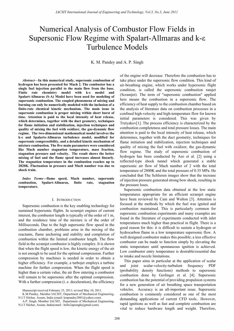
A. Physical Model A mathematical model comprises equations relating the
dependent and the independent variables and the relevant parameters that describe some physical phenomenon. Typically, a mathematical model consists of differential equations that govern the behavior of the physical system, and the associated boundary conditions.
Figure 1 Physical model of Supersonic Combustor
B. Governing Equations The advantage of employing the complete Navier-Stokes
equations extends not only o the investigations that can be carried out on a wide range of flight conditions and geometries, but also in the process the location of shock wave, as well as the physical characteristics of the shock layer, can be precisely determined. We begin by describing the three-dimensional forms of the Navier-Stokes equations below. Note that the two-dimensional forms are just simplification of the governing equations in the three dimensions by the omission of the component variables in one of the co-ordinate directions. Neglecting the presence of body forces and volumetric heating, the three-dimensional Navier-Stokes equations are derived as [14, 15, 17, and 18] Continuity:
+ ( ) + ( ) + ( ) = 0 (1) X-momentum:
IACSIT International Journal of Engineering and Technology, Vol.3, No.3, June 2011
209
( ) + ( ) + ( ) + ( ) = + + (2)
Y-momentum: ( ) + ( ) + ( ) + ( ) = + +
(3) Z-momentum:
( ) + ( ) + ( ) + ( ) = + +
(4) Energy:
( E) + ( E) + ( E) + ( E) = ( ) + ( ) + ( ) + ( T)
+ ( T)
+ ( T) (5)
Assuming a Newtonian fluid, the normal stress σxx, σyy, and σzz can be taken as combination of the pressure p and the normal viscous stress components τxx, τyy, and τzz while the remaining components are the tangential viscous stress components whereby τxy= τyx, τxz= τzx, and τyz= τzy. For the energy conservation for supersonic flows, the specific energy E is solved instead of the usual thermal energy H applied in sub-sonic flow problems. In three dimensions, the specific energy E is repeated below for convenience:
E = e + (u2 + v2 + w2) (6) It is evident from above that the kinetic energy term
contributes greatly to the conservation of energy because of the high velocities that can be attained for flows, where Ma>1. Equations (1)-(6) represent the form of governing equations that are adopted for compressible flows.
The solution to the above governing equations nonetheless requires additional equations to close the system. First, the equation of state on the assumption of a perfect gas in employed, that is,
P=ρRT, where R is the gas constant. Second, assuming that the air is calorically perfect, the
following relation holds for the internal energy: e= CvT,
Where Cv is the specific heat of constant volume. Third, if the Prandtl number is assumed constant (approximately 0.71 for calorically perfect air), the thermal conductivity can be evaluated by the following:
k=μC
The Sutherland’s law is typically used to evaluate viscosity
µ, which is provided by
µ=µ0 . (7)
where µ0 and T0 are reference values at standard sea level conditions.
Generalized form of Turbulence Equations is as follows: ( ) + ( ) + ( ) + ( ) = + + + (Sk=P – D)
( ) + ( ) + ( ) + ( ) = + + + ( = ( ) Where = 2 + + + ++ + + + =
C. Reaction Model The instantaneous reaction model assumes that a single
chemical reaction occurs and proceeds instantaneously to completion. The reaction used for the Scramjet was the hydrogen-water reaction:
2H2 + O2 → 2H2O. (8)
D. The Equilibrium Model The equilibrium model requires the specification of all the
chemical species that might exist in the reacting mixture. No specific reactions need to be specified. This reaction model calculates the species concentrations at its equilibrium condition. The species specified for the reaction mixture were: H2, O2, N2, H2O, OH, O and NO.
The multi-step finite rate reaction model uses chemical rate equations to model any number reaction occurring in the system. The reaction rates are calculated using the Arrhenius equation: k = A T e( E RT⁄ ) (9) where: k is the reaction rate coefficient AP is the pre- exponential constant Ea/R is the activation temperature n is the temperature exponent.
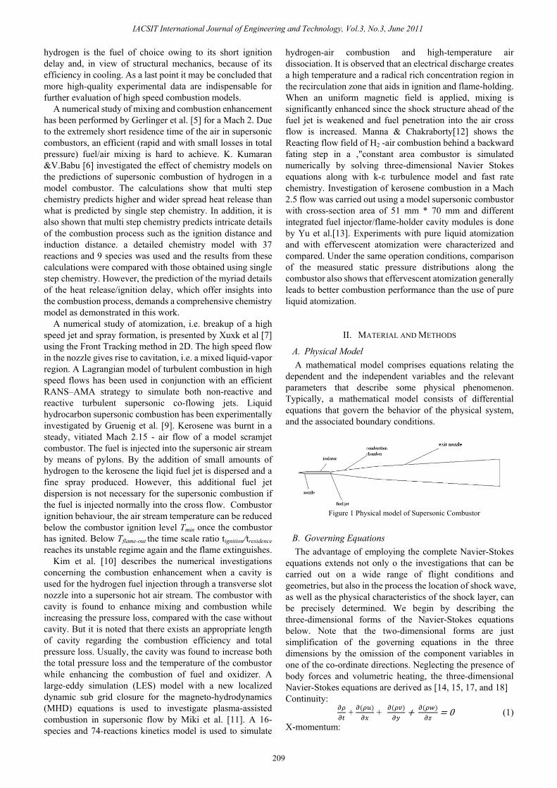
E. Geometry and Grid Arrangement The geometry 2d axi-symmetric computational domain
was considered for the simulation of supersonic combustion , the initial design parameters for de Laval nozzle has taken at Mach 2 This was obtained by method of characteristics of nozzle program. The injector Diameter is 0.005m and the length of the combustor is 2m from throat and exit diameter is 0.2m.
Figure 3 Close look of Supersonic Combustor at Mach 2
Figure2 Supersonic Combustor at Mach 2
IACSIT International Journal of Engineering and Technology, Vol.3, No.3, June 2011
210
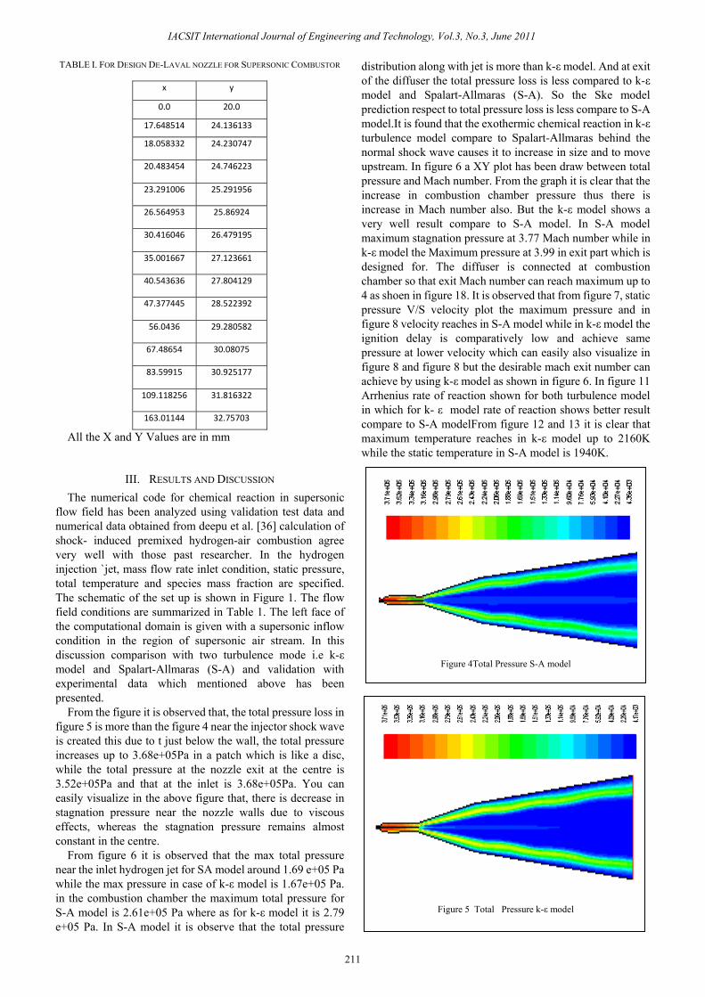
TABLE I. FOR DESIGN DE-LAVAL NOZZLE FOR SUPERSONIC COMBUSTOR
x y
0.0 20.0
17.648514 24.136133
18.058332 24.230747
20.483454 24.746223
23.291006 25.291956
26.564953 25.86924
30.416046 26.479195
35.001667 27.123661
40.543636 27.804129
47.377445 28.522392
56.0436 29.280582
67.48654 30.08075
83.59915 30.925177
109.118256 31.816322
163.01144 32.75703
All the X and Y Values are in mm
III. RESULTS AND DISCUSSION The numerical code for chemical reaction in supersonic
flow field has been analyzed using validation test data and numerical data obtained from deepu et al. [36] calculation of shock- induced premixed hydrogen-air combustion agree very well with those past researcher. In the hydrogen injection `jet, mass flow rate inlet condition, static pressure, total temperature and species mass fraction are specified. The schematic of the set up is shown in Figure 1. The flow field conditions are summarized in Table 1. The left face of the computational domain is given with a supersonic inflow condition in the region of supersonic air stream. In this discussion comparison with two turbulence mode i.e k-ε model and Spalart-Allmaras (S-A) and validation with experimental data which mentioned above has been presented.
From the figure it is observed that, the total pressure loss in figure 5 is more than the figure 4 near the injector shock wave is created this due to t just below the wall, the total pressure increases up to 3.68e+05Pa in a patch which is like a disc, while the total pressure at the nozzle exit at the centre is 3.52e+05Pa and that at the inlet is 3.68e+05Pa. You can easily visualize in the above figure that, there is decrease in stagnation pressure near the nozzle walls due to viscous effects, whereas the stagnation pressure remains almost constant in the centre.
From figure 6 it is observed that the max total pressure near the inlet hydrogen jet for SA model around 1.69 e+05 Pa while the max pressure in case of k-ε model is 1.67e+05 Pa. in the combustion chamber the maximum total pressure for S-A model is 2.61e+05 Pa where as for k-ε model it is 2.79 e+05 Pa. In S-A model it is observe that the total pressure
distribution along with jet is more than k-ε model. And at exit of the diffuser the total pressure loss is less compared to k-ε model and Spalart-Allmaras (S-A). So the Ske model prediction respect to total pressure loss is less compare to S-A model.It is found that the exothermic chemical reaction in k-ε turbulence model compare to Spalart-Allmaras behind the normal shock wave causes it to increase in size and to move upstream. In figure 6 a XY plot has been draw between total pressure and Mach number. From the graph it is clear that the increase in combustion chamber pressure thus there is increase in Mach number also. But the k-ε model shows a very well result compare to S-A model. In S-A model maximum stagnation pressure at 3.77 Mach number while in k-ε model the Maximum pressure at 3.99 in exit part which is designed for. The diffuser is connected at combustion chamber so that exit Mach number can reach maximum up to 4 as shoen in figure 18. It is observed that from figure 7, static pressure V/S velocity plot the maximum pressure and in figure 8 velocity reaches in S-A model while in k-ε model the ignition delay is comparatively low and achieve same pressure at lower velocity which can easily also visualize in figure 8 and figure 8 but the desirable mach exit number can achieve by using k-ε model as shown in figure 6. In figure 11 Arrhenius rate of reaction shown for both turbulence model in which for k- ε model rate of reaction shows better result compare to S-A modelFrom figure 12 and 13 it is clear that maximum temperature reaches in k-ε model up to 2160K while the static temperature in S-A model is 1940K.
Figure 5 Total Pressure k-ε model
Figure 4Total Pressure S-A model
IACSIT International Journal of Engineering and Technology, Vol.3, No.3, June 2011
211
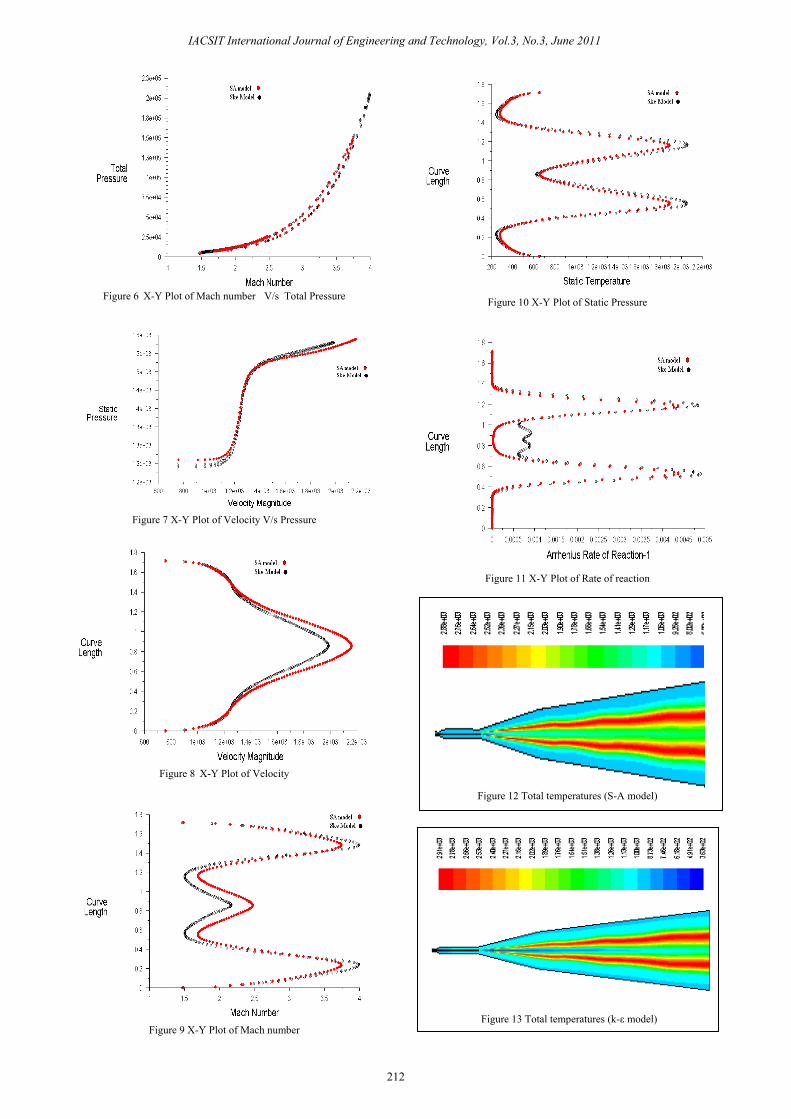
Figure 6 X-Y Plot of Mach number V/s Total Pressure
Figure 7 X-Y Plot of Velocity V/s Pressure
Figure 8 X-Y Plot of Velocity
Figure 9 X-Y Plot of Mach number
Figure 10 X-Y Plot of Static Pressure
Figure 11 X-Y Plot of Rate of reaction
Figure 13 Total temperatures (k-ε model)
Figure 12 Total temperatures (S-A model)
IACSIT International Journal of Engineering and Technology, Vol.3, No.3, June 2011
212
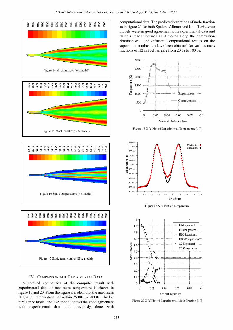
IV. COMPARISON WITH EXPERIMENTAL DATA A detailed comparison of the computed result with
experimental data of maximum temperature is shown in figure 19 and 20. From the figure it is clear that the maximum stagnation temperature lies within 2500K to 3000K. The k-ε turbulence model and S-A model Shows the good agreement with experimental data and previously done with
computational data. The predicted variations of mole fraction as in figure 21 for both Spalart- Allmars and K-� Turbulence models were in good agreement with experimental data and flame spreads upwards as it moves along the combustion chamber wall and diffuser. Computational results on the supersonic combustion have been obtained for various mass fractions of H2 in fuel ranging from 20 % to 100 %.
Figure 18 X-Y Plot of Experimental Temperature [19]
Figure 19 X-Y Plot of Temperature
Figure 20 X-Y Plot of Experimental Mole Fraction [19]
Figure 17 Static temperatures (S-A model)
Figure 16 Static temperatures (k-ε model)
Figure 15 Mach number (S-A model)
Figure 14 Mach number (k-ε model)
IACSIT International Journal of Engineering and Technology, Vol.3, No.3, June 2011
213
Figure 21 X-Y Plot of Mole Fraction
V. CONCLUSION With the improved detailed geometry using isolator to
de-accelerate the flow, it is observed that the nozzle and diffuser which designed for flow travel along with the direction and at throat Mach number is 1. From the geometry results shows the better mixing in combustion chamber, caused by more extreme shear layers and stronger shocks are induced which leads loss in total pressure of the supersonic stream. The k-ε model and S-A model is able to predict the fluctuation well in that region where the turbulence is reasonably isotropic. The result is validating with mathematical procedure of method of characteristics to designing a nozzle and experimental data shows the good agreement with computational data. Fluctuation in pressure and Mach number was due to shock train.At and near the strongly reacting region, the turbulence field is intensified by the extra strains caused by chemical reactions. Due to the intensified turbulence field in the region, the thickness of the shear layer is increased and the chemical species exhibit wider distribution across the shear layer.
ACKNOWLEDGMENT The authors acknowledge the valuable suggestions from
Prof. E. Rathakrishnan, Professor, Department of aerospace engineering, IIT Kanpur, India. The authors acknowledge the financial help provided by AICTE from the project AICTE: 8023/RID/BOIII/NCP (21) 2007-2008 .The Project id at IIT Guwahati is ME/P/USD/4.
REFERENCES [1] P.K. Tretyakov “The Problems of Combustion at Supersonic Flow”
West-East High Speed Flow Field Conference 19-22, November 2007. [2] Shigeru Aso, Arifnur Hakim, Shingo Miyamoto, Kei Inoue and
Yasuhiro Tani “Fundamental Study Of Supersonic Combustion In Pure Air Flow With Use Of Shock Tunnel”, Acta Astronautica 57 (2005) 384 – 389.
[3] T. Cain And C. Walton “Review Of Experiments On Ignition And Flame Holding In Supersonic Flow” Published By The America Institute Of Aeronautics And Astronautics, Rto-Tr-Avt-007-V2.
[4] H. Mo¨Bus, P. Gerlinger, D. Bru¨Ggemann “Scalar and Joint Scalar- Velocity- Fequency Monte Carlo Pdf Simulation Of Supersonic Combustion” Combustion And Flame 132 (2003) 3–24.
[5] Peter Gerlinger, Peter Stoll , Markus Kindler , Fernando Schneider C, Manfred Aigner “Numerical Investigation Of Mixing And Combustion Enhancement In Supersonic Combustors By Strut Induced Streamwise Vorticity”, Aerospace Science And Technology 12 (2008) 159–168.
[6] K. Kumaran, V. Babu “Investigation o The Effect Of Chemistry Models On The Numerical Predictions Of The Supersonic Combustion Of Hydrogen”, Combustion And Flame 156 (2009) 826–841.
[7] Zhiliang Xuxk, Myoungnyoun Kimxk, Wonho Ohzk, James Glimmzxk, Roman Samulyakx, Xiaolin Liz And Constantine Tzanos “Atomization Of A High Speed Jet” April 14, 2005, U.S. Department Of Energy
[8] Jean-Francois Izard , Arnaud Mura “Stabilization Of Non-Premixed Flames In Supersonic Reactive Flows” Combustion For Aerospace Propulsion, Cras2b:2818,
[9] C. Gruenig And F. Mayinger “Supersonic Combustion Of Kerosene/H2-Mixtures In A Model Scramjet Combustor” , Institute A For Thermodynamics, Technical University Munich, D-85747.
[10] Kyung Moo Kim , Seung Wook Baek , Cho Young Han “ Numerical Study On Supersonic Combustion With Cavity-Based Fuel Injection”, International Journal Of Heat And Mass Transfer 47 (2004) 271–286 ,
[11] Kenji Miki, Joey Schulz, Suresh Menon “Large-Eddy Simulation Of Equilibrium Plasma-Assisted Combustion In Supersonic Flow”, Proceedings Of The Combustion Institute 32 (2009) 2413–2420, Atlanta, Ga 30332-0150,
[12] P Manna, D Chakraborty “Numerical Simulation Of Transverse H2 Combustion In Supersonic Airstream In A Constant Area Duct”, ARTFC, Vol. 86, November 2005.
[13] G. Yu, J.G. Li, J.R. Zhao, L.J. Yue, X.Y. Chang, C.-J. Sung “An Experimental Study Of Kerosene Combustion In A Supersonic Model Combustor Using Effervescent Atomization”, Proceedings Of The Combustion Institute 30 (2005) 2859–2866,
[14] K.M. Pandey and A.P Singh, “CFD Analysis of Conical Nozzle For Mach 3 at Various Angles of Divergence With Fluent Software” International Journal of chemical Engineering and Application ,Vol.-1, No. 2, August 2010,ISSN- 2010-0221, pp 179-185.
[15] K.M. Pandey and A.P Singh, “Numerical Analysis of Supersonic Combustion by Strut Flat Duct Length with S-A Turbulence Model” IACSIT International Journal of Engineering and Technology, Vol.-3, No. 2, April 2010, pp 193-198.
[16] P. Magre, G. Collin, O. Pin, J.M Badie, G. Olalde And M. Clement, Temperature Measurement By Cars And Intrusive Probe In An Air-Hydrogen Supersonic Combustion, International Journal Of Heat And Mass Transfer 44(2001) 4095-4105.
[17] Jiyun tu, guan Heng yeoh and chaoqun liu. “Computational Fluid Dynamics” Elsevier Inc. 2008.
[18] K.M. Pandey and A.P Singh, “Recent Advances in Experimental and Numerical Analysis of Combustor Flow Fields in Supersonic Flow Regime” International Journal of chemical Engineering and Application,Vol.-1, No. 2, August 2010,ISSN- 2010-0221, pp 132-137.
[19] Deepu, Mukundan N., Gokhale, Sadanand. S., jayaraj, Simon, “Numerical Analysis of Supersonic combustion using unstructured Point Implict finite Volume Method”, Journal of combustion Society of Japan, Vol. 48 No. 144(2006) 187-197.
IACSIT International Journal of Engineering and Technology, Vol.3, No.3, June 2011
214
Dr. K.M.Pandey obtained PhD in Mechanical Engineering in 1994 from IIT Kanpur. He has published and presented 200 papers in International & National Conferences and Journals. Currently he is working as Professor of the Mechanical .Engineering Department, National Institute of Technology, Silchar, Assam, India.He has also served the department in the capacity of head from July 07 to 13 July 2010. He has worked as
faculty consultant in Colombo Plan Staff College, Manila, Philippines as seconded faculty from Government of India. His research interest areas are the following; Combustion, High Speed Flows, Technical Education, Fuzzy Logic and Neural Networks , Heat Transfer, Internal Combustion Engines, Human Resource Management, Gas Dynamics and Numerical Simulations in CFD area from Commercial Softwares.


![Instructional workshop on OpenFOAM programming LECTURE # 8€¦ · localDt[ myCell ] += lambda * face_area;}} Hands on - Supersonic ow over wedge I Compile the solver I Setup inputs](https://static.fdocument.org/doc/165x107/606261e2a9a908738c306e77/instructional-workshop-on-openfoam-programming-lecture-8-localdt-mycell-.jpg)