notice Max Prop “tripale” - France Helices · 2 1 - REGLAGE DU PAS - PITCH ADJUSTMENT Le pas de...
12
Notice MAX PROP “TRIPALE”
Transcript of notice Max Prop “tripale” - France Helices · 2 1 - REGLAGE DU PAS - PITCH ADJUSTMENT Le pas de...
Notice MAX PROP“TRIPALE”
2
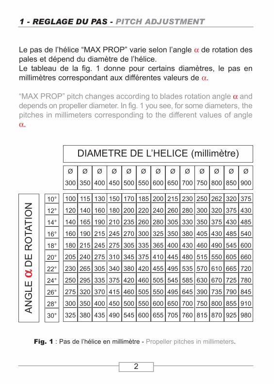
1 - REGLAGE DU PAS - PITCH ADJUSTMENT
Le pas de l’hélice “MAX PROP” varie selon l’angle α de rotation despales et dépend du diamètre de l’hélice. Le tableau de la fig. 1 donne pour certains diamètres, le pas enmillimètres correspondant aux différentes valeurs de α.
“MAX PROP” pitch changes according to blades rotation angle α anddepends on propeller diameter. In fig. 1 you see, for some diameters, thepitches in millimeters corresponding to the different values of angleα.
Fig. 1 : Pas de l’hélice en millimètre - Propeller pitches in millimeters.
10°
12°
14°
16°
18°
20°
22°
24°
26°
28°
30°
AN
GLE
ααD
ER
OTA
TIO
N
100
120
140
160
180
205
230
250
275
300
325
115
140
165
190
215
240
265
295
320
350
380
130
160
190
215
245
275
305
335
370
400
435
150
180
210
245
275
310
340
375
415
450
490
170
200
235
270
305
345
380
420
460
500
545
185
220
260
300
335
375
420
460
505
550
600
200
240
280
325
365
410
455
505
550
600
655
215
260
305
350
400
445
495
545
495
650
705
230
280
330
380
430
480
535
585
645
700
760
250
300
350
405
460
515
570
630
390
750
815
262
320
375
430
490
550
610
670
735
800
870
320
375
430
485
545
605
665
725
790
855
925
375
430
485
540
600
660
720
780
845
910
980
DIAMETRE DE L’HELICE (millimètre)
Ø
300
Ø
350
Ø
400
Ø
450
Ø
500
Ø
550
Ø
600
Ø
650
Ø
700
Ø
750
Ø
800
Ø
850
Ø
900
4
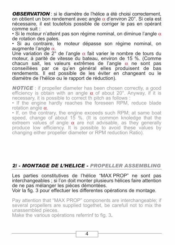
OBSERVATION : si le diamètre de l’hélice a été choisi correctement,on obtient un bon rendement avec angle α d’environ 20°. Si cela estnécessaire, il est toutefois possible de corriger le pas en opérantcomme suit :• Si le moteur n’atteint pas son régime nominal, on diminue l’angle αde rotation des pales.• Si au contraire, le moteur dépasse son régime nominal, on augmente l’angle α.Une variation de 2° de l’angle α fait varier le nombre de tours dumoteur, à parité de vitesse du bateau, environ de 15 %. (Commechacun sait, les valeurs extrêmes de l’angle α ne sont pasconseillées par ce qu’en général elles produisent de bas rendements. Il est possible de les éviter en changeant ou le diamètre de l’hélice ou le rapport de réduction).
NOTICE : if propeller diameter has been chosen correctly, a goodefficiency is obtain with an angle α of about 20°. Anyway, if it isnecessary, it is possible to correct th pitch as follows :• If the engine hardly reaches the foreseen RPM, reduce blade rotation angle α.• If, on the contrary, the engine exceeds such RPM; at same boatspeed, change of about 15 %. (It is common knoledge that the extreem values of angle α are not advisable, as they generally produce low efficiency. It is possible to avoid these values by changing either propeller diameter or RPM reduction Ratio).
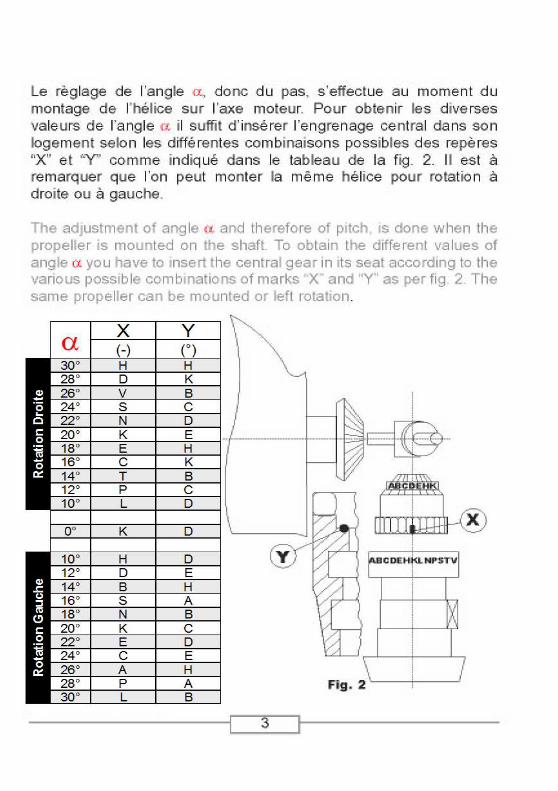
2/ - MONTAGE DE L’HELICE - PROPELLER ASSEMBLING
Les parties constitutives de l’hélice “MAX PROP” ne sont pas interchangeables ; si l’on doit monter plusieurs hélices faire attentionde ne pas mélanger les pièces démontées.Voir la fig. 3 pour effectuer les differentes opérations de montage.
Pay attention that “MAX PROP” components are interchangeable; ifseveral propellers are supplied togethet, be carefull not to mix theunassembled pieces.Make the various opérations referrinf to fig. 3.
5
9
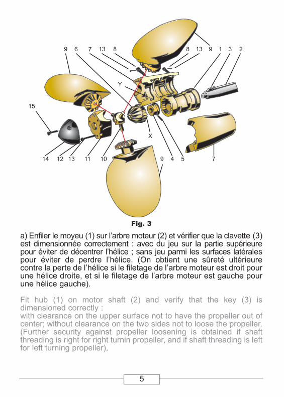
a) Enfiler le moyeu (1) sur l’arbre moteur (2) et vérifier que la clavette (3)est dimensionnée correctement : avec du jeu sur la partie supérieurepour éviter de décentrer l’hélice ; sans jeu parmi les surfaces latéralespour éviter de perdre l’hélice. (On obtient une sûreté ultérieure contre la perte de l’hélice si le filetage de l’arbre moteur est droit pourune hélice droite, et si le filetage de l’arbre moteur est gauche pourune hélice gauche).
Fit hub (1) on motor shaft (2) and verify that the key (3) is dimensioned correctly :with clearance on the upper surface not to have the propeller out ofcenter; without clearance on the two sides not to loose the propeller.(Further security against propeller loosening is obtained if shaftthreading is right for right turnin propeller, and if shaft threading is leftfor left turning propeller).
Fig. 3
6 7 13 8 8 13 9 1 3 2
7549
X
1011131214
15
Y
6
B) Bloquer fortement l’écrou (4) et l’assurer avec la goupille (5), ilfaut noter que l’extrémité filetée de l’arbre moteur ne doit que légèrement dépasser l’écrou (4) : si cette extrémité dépasse trop fortement et entre en contact avec l’intérieur de l’engrenage (6) il fautcouper la partie excédante.
Tighten well the nut (4) and secure it against loosening a pin (5).Note that the threaded edge of shaft must protrude little from the nut(4); if it protrudes too much, and touches the inside of the gear (6), itis necessary to cut the exceeding part.
C) Engager l’engrenage central (6) dans son logement du moyeu (1)(veillez à ce que l’encoche de repère “X” soit mise dans la positioncorrecte établie et basée sur le pas que l’on veut donner à l’hélice).
Insert the central gear (6) in its seat in the hub (1) (pay attention thatthe mark “X” is placed in th correct position chosen according to thepitch you want to give to the propeller).
D) remplir complètement avec de la graisse marine les deux moitiésde l’ogive (7) et les fermer sur le moyeu (1) avec les vis (1).
Fill completely the two halves of spinner (7) with sea water proofgrease and close them on hub (1) with screws (8).
E) Faire tourner l’ogive (7) sur le moyeu (1) jusqu’à faire coïncider lerepère “Y” (qui est constitué par un petit trou pratiqué dans l’ogive)avec la dent de l’engrenage conique (6) établie au pas que l’on veutdonner à l’hélice.
Make the spinner (7) rotate on hub (1) untill mark “Y” (made by asmall hole in the spinner) coincide with that tooth of conical gear (6)chosen according to the pitch you want to give to the propeller.
F) Enfiler les trois pales (9) sur les pivots de l’entretoise (10).Insert the three blades (9) on the three pins of soacer (10).
G) Insérer le groupe (9) + entretoise (10) dans les trois sièges de l’o-give (7) en travaillant de cette façon :- Tenir les trois pales (9) pressées contre l’entretoise (10) orientéesselon leur position en drapeau (parfaitement alignées avec l’axe del’ogive).- Observer l’exacte position des repères pales-ogives 1-1, 2-2, 3-3.- Ne pas remuer l’ogive (7) en comparaison du moyeu (1) car le repè-re “Y” ne doit pas être déplacé de la position choisie. Pour faciliterl’opération fixer éventuellement l’ogive (7) à la partie saillante dumoyeu (1) avec du rubn adhésif qui sera emporté à montage fini.

7
Fig. 4 Fig. 5NONNO
OUIYES
DESSERAGE | UNSCREWING
H) Remplir complètement avec de la graisse marine la partie terminale (11) et la fixer à l’ogive (7) par les vis (12). (Observerl’exact position des repères)
Fill the end part (11) completely with sea water proof grease and fixit to the spinner (7) by screws (12). Note the correct position ofmarks) .I) Pour rendre plus facile la rotation des pales, il est convenable,après avoir serré les vis, de donner des coups sur l’hélice avec lamassette en plastique.
To let the blades rotates more freely, it is advisable, after having tightened all the screws, to give some bedding blows on propellerwith a plastic mallet
Pour éviter le desserrage insérer dans la tête de chaque vis (commeindiqué par la fig. 4) une goupille (13). Enfoncer les goupilles avecde légers coups de marteau, de manière à les faire avancer le moinspossible de la tête des vis. ensuite l’extrémité des goupilles avec untournevis (fig. 5).
For safety against loosening insert in the head of each screw (in theposition of fig. 4) a split-pin (13). Drive the split-pin fully in with lighthammer blows, so that they protrude as little as possible from thescrew head. Then spread the ends of the split-pins open with a screwdriver (fig. 5).
Insert the group blades (9) + spacer (10) in the three seats of spin-ner (7) opérating this way :- Keep the three blades (9) pressed to the spacer (10), and placed infeathered position (perfectly lined up to spinner axis).- Control the correct position of blade-spinner marks 1-1, 2-2, 3-3.Not to move spinner (7) from hub (1) because mark “Y” must not bemoved from selected position. To make the operation easier the spin-ner (7) can even be fixed to protruding edge og hub (1) by a piece ofadhesive tape that you can take off when the propeller is assembled.
8
Fig. 6 Fig. 7
NONNO
OUIYES
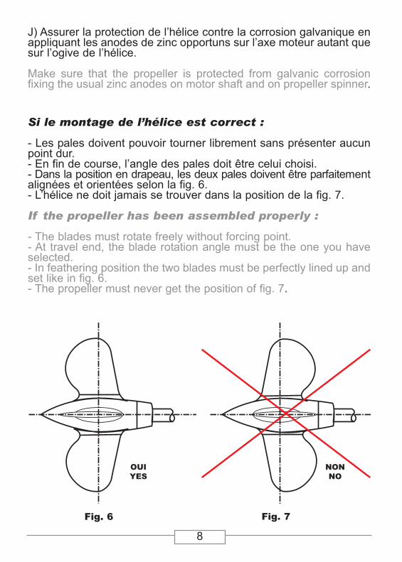
J) Assurer la protection de l’hélice contre la corrosion galvanique enappliquant les anodes de zinc opportuns sur l’axe moteur autant quesur l’ogive de l’hélice.
Make sure that the propeller is protected from galvanic corrosionfixing the usual zinc anodes on motor shaft and on propeller spinner.
Si le montage de l’hélice est correct :
- Les pales doivent pouvoir tourner librement sans présenter aucunpoint dur.- En fin de course, l’angle des pales doit être celui choisi.- Dans la position en drapeau, les deux pales doivent être parfaitementalignées et orientées selon la fig. 6.- L’hélice ne doit jamais se trouver dans la position de la fig. 7.
If the propeller has been assembled properly :
- The blades must rotate freely without forcing point.- At travel end, the blade rotation angle must be the one you haveselected.- In feathering position the two blades must be perfectly lined up andset like in fig. 6.- The propeller must never get the position of fig. 7.

9
3 FONCTIONNEMENT DE L’HELICEPROPELLER WORKING
L’hélice “MAX PROP” fonctionne de façon complètement automatique. Elle prend le pas quand on tourne l’arbre moteur enmarche avant et en marche arrière. Elle se met en drapeau quandelle est arrêtée dans la position de marche avant même avec unetrès petite vitesse (1,5/2 noeuds).
“MAX PROP” propeller works completely automatically. It gets thepitch when you make the engine shaft turning forward and background. If feathers when it is stoped in forward position and isdragged by the boat even at a very low (1,5/2 knots).
4 ENTRETIENT DE L’HELICEPROPELLER MAINTENANCE
Vérifier que l’ogive est complètement pleine de graisse, et que leszincs de protection ne sont pas consumés.
Verify that the spinner is still completely full of grease, and that thesacrifical zinc anodes are not worn out.
10
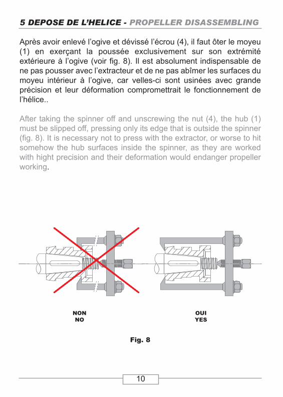
5 DEPOSE DE L’HELICE - PROPELLER DISASSEMBLING
Après avoir enlevé l’ogive et dévissé l’écrou (4), il faut ôter le moyeu(1) en exerçant la poussée exclusivement sur son extrémité extérieure à l’ogive (voir fig. 8). Il est absolument indispensable dene pas pousser avec l’extracteur et de ne pas abîmer les surfaces dumoyeu intérieur à l’ogive, car velles-ci sont usinées avec grande précision et leur déformation compromettrait le fonctionnement del’hélice..
After taking the spinner off and unscrewing the nut (4), the hub (1)must be slipped off, pressing only its edge that is outside the spinner(fig. 8). It is necessary not to press with the extractor, or worse to hitsomehow the hub surfaces inside the spinner, as they are workedwith hight precision and their deformation would endanger propellerworking.
Fig. 8
NONNO
OUIYES

11
MODELE EN BRONZE AVEC OGIVE TREMPEEBRONZE MODEL WITH HARDENED SPINNER

12
CANNES LA BOCCAZ.I. la Frayère
06150 CANNES LA BOCCA
CONCARNEAUZ.I. de Kersalé
29900 CONCARNEAU
DAMMARIE LES LYS249, avenue de Seine
77190 DAMMARIE LES LYS
CONTACTTél. : + 33 (0)4 93 47 69 38Fax : + 33 (0)4 93 47 08 59
FRANCE
Toute la gamme de nos produits est disponible sur notre site Internet
All our products are available on our web site